chapter 2 · nyquist, shannon the noise presence is appreciated by the signal to noise ratio = the...
TRANSCRIPT

The Physical Layer
Chapter 2

The Physical Layer
• Defines the mechanical, electrical and timing interfaces to the network
• Transmission media- guided (copper and fiber optics)- wireless (radio terrestrial)- satellite

The Theoretical Basis for Data Communication
• Fourier Analysis• Bandwidth-Limited Signals• Maximum Data Rate of a Channel

Time- domain representation of signals
Fig.2-1 (a) continuous time signal(b) discrete time signal
1,5
-2 -1 0 1 2 3 4 5 6
2
x[n] ; n∈Z
n-1
x(t); t∈R
t
(b)(a)

Representation of the sine wave signal (fundamental continuous signal)
Fig.2-2 (a) Time domain representation and(b) frequency domain representation of the sine wave signal
x(t) [V]
t [ms] ( ) 310 2 10 [ ]x t sin t V= π⋅
Amplitudine
Linia spectrală a sinusoidei
0 0,5 1 1,5 2 f [kHz]
10
(a)
(b)

Frequency domain concepts
Fig. 2-3 Time domain and frequency domain representation for periodic signals
(a)
(b)
t [ms]
x(t), x1(t), x2(t)
Semnal sumă
( )( )( ) ( ) ( )txtxtx
tsintx
tsintx
21
32
31
1032
1023
+=⋅⋅=
⋅⋅=
π
π
Amplitudine
0 0,5 1 1,5 2 f [kHz]
2,5 3 3,5
A
A/3

Frequency domain concepts- periodic signals
(b)
(a) ∑∑∞
=
∞
=
++=1
001
0
2)(
0k
kk
kT tksinbtkcosaa
tx ωω
( ) ( )∑∞
=
+⋅=0
cos0
kkokT tkAtx ϕω
∫=0
0)(1
2 0
0
TT dttx
Ta
dttkcostxT
aT
Tk 00 0
0)(2 ω∫= dttksintx
Tb
TTk 0
0 0
0)(2 ω∫=
( ) ∑∞
−∞=
⋅=k
tjkkT ectx 0
0
ω
( )∫ ⋅⋅= −
0
0
00
1
T
tjkTk dtetx
Tc ω
{ }⎪⎩
⎪⎨
⎧
==
=
00
2
Accarg
Ac
kk
kk
ϕ
(c)

Frequency domain concepts- periodic signals
- 1
1
0 T 0 T 0 /2
τ
t
x ( t )
( ) ( )∑∞
=⎥⎦⎤
⎢⎣⎡ −+
+⋅=
00 2
1212
14k
tkcosk
tx πωπ
π 4
k 1
ω 0
ω 0 3 ω 0
5 ω 0
A k
7ω0
ω
ω 0 3ω0 5ω0 7ω0
-π/2
ϕ k
11,0 AAk ⋅≥ ][9 0 HzfBef ⋅=
a)
Fig. 2-4 Time domain (a) and frequency domain (b) representation for square wave signal
b)
4(2 1)kA
k=π +

Frequency domain concepts- aperiodic signals
1/τ
t
x ( t )
2 τ
2 τ
−
∫∞
∞−
− ∈∀= RdtetxX tj ωω ω ;)()(
⎪⎪⎩
⎪⎪⎨
⎧
>
<=
2;0
2;1
)(τ
ττ
tpentru
tpentrutx
∫−
− ==2
2
2)(
τ
τ
ω ωτω sincdteX tj
X(ω)
ω
1
0
τ
π2
τ
π2−
τ
π4
τ
π4−
τ
π6
τ
π6−
ω
2π⏐X(ω)⏐2
1
{ } )()()( ωω txX ℑ=
Fig. 2-5

Relationship between data rate and bandwidth
- 1
1
0 T 0 T 0 /2
τ
t
x ( t )
0
12 2T
fτ = =
π 4
k 1
ω 0
ω 0 3 ω 0
5 ω 0
A k
7ω0
02data rate f bps=
0
0
1(5 1) 4
2
f MHzB f MHzdata rate Mbps
== − ⋅ =
=
a)
Fig. 2-4 Time domain (a) and frequency domain (b) representation for square wave signal
b)
1) Digital transmission BC =4MHz
2) Digital transmission BC =8MHz
'0 0
0
2 2(5 1) 2 8
4
f MHz fB f MHzdata rate Mbps
= =
= − ⋅ =
=

Bandwidth-Limited Signals
Fig. 2-6 Effect of bandwidth on a digital signal

Bandwidth-Limited Signals (2)
(d) – (e) Successive approximations to the original signal.

Bandwidth-Limited Signals (3)
Fig. 2-7 Relation between data rate and harmonics
0
8 sec
3000 2400030008
8
C
bitrate b bps
tb
bf Hz B Hz b b
=
=
= = ⇒ =

Maximum data rate of a channel
2max / sec log (1 / )imum number of bits H S N= +
2max 2 logimum data rate H V bps=
Nyquist, Shannon
The noise presence is appreciated by the signal to noise ratio = the ratio of the signal power to the noise power S/NUsually the ratio itself is not quoted; instead the quantity is given
The units are called decibels (dB)
Shannon’s major result is that the maximum data rate of a noisy channel whose bandwidth is H Hz and whose signal - to - noise ratio is S/N is given by:
1010log SN

Maximum data rate of a channel
2max / sec log (1 / )imum number of bits H S N= +
Expl: A channel of 3100Hz bandwidth with a signal to thermal noise ratio of 30dB (typical parameter of the analog part of the telephone system) can never transmit much more than 30000bps
The capacity indicated is referred to as the error free capacity
NOTE – if the actual information rate on a channel is less than the error-free capacity than it is theoretically possible to use a suitable signal code to achieve error-free transmission through the channel
- Shannon’s theorem does not suggest a means for finding such codes
The measure of efficiency of a digital transmission is the ratio: C/H [bps/Hz]
23100 log (1 1000) 30894C bps= ⋅ + =

Bandwidth, bit rate, transmission time
Many people confuse bandwidth and bit rate, but you should keep the distinctionThe bit rate and the number of bits to transmit determine the transmission time.

Propagation

Propagation(2)
• Propagation is the time taken by the front of a signal to reach the destination. It is independent of the bit rate.
• Propagation of an electromagnetic signal is the speed ( also called celerity) of light. It depends on the wavelength and the element in which the signal is propagating.
• Acoustic waves move at 300m/s. What is the propagation time if we use an acoustic phone system between two cities which are 1000 km apart?

Propagation(3)
0.1 800 800.1ms ms ms+ =
820 0.1
2 10 /km msm s
=⋅
Examples
1- way propagation time =
transmission time =
reception time =
31000 8 800
10 10 /b ms
b s⋅
=⋅

Throughput
Defines how much data can be moved by time unit. It is equal to the bit rate if there is no protocol. However in most practical cases the throughput is less than the bit rate for two reasons:
- protocol overhead: protocols like UDP use some bytes to transmit protocol information. This reduces throughput. If you send one-byte message with UDP then for every byte you create an Ethernet packet of size: 1+8+20+26 = 53bytes thus the maximum throughput you could ever get at UDP service interface if you use a 64kb/s channel would be 1.2 kb/s.
- protocol waiting times: some protocols may force you to wait for some event.

Analog and Digital Data Transmission
• The nature of data
• The actual physical means used to propagate the data
• What processing or adjustments may be required along the way to ensure that the received data are intelligible
Analog and digital
• Data• Signaling• Transmission

Analog and Digital Data Transmission
• Data- Expl:
- Audio or acoustic data: frequency components: 20Hz –20kHz – analog data-Video data in terms of the viewer – analog dataText or character strings – digital data- codes used for representing each character by a sequence of bits: ASCII( American Standard Code for Information Interchange)- 7 bits
• Signals- Acoustic data – spectrum of speech: 20Hz – 20kHz
– standard spectrum for voice signal: 300Hz- 3400Hz
- Video data – Video signal: bandwidth: 4MHz

Analog and Digital Data Transmission
• Binary digital data- The bandwidth will depend in any specific case on the exact shape of the wave form and on the sequence of 1s and 0s.

Analog and Digital Data Transmission
• Data and signals
TelephoneAnalog signalAnalog data
(voice sound waves)
ModemDigital data Analog signal
(binary voltage pulses)
CodecDigital signalAnalog data
Digital transmitterDigital data Digital signal
(a) Analog signals; represent data with continuously varying electromagnetic wave
(b) Digital signals; represent data with sequence of voltage pulses

Analog and Digital Data Transmission
• Transmission –(a) data and signals
Two alternatives: (1) signal consists of two voltage levels to represent the two binary values; (2) digital data are encoded to produce a digital signal with desired properties
Digital data are encoded using a modem to produce analog signal
Digital data
Analog data are encoded using a codec to produce a digital bit stream;
Two alternatives: (1) signal occupies the same spectrum as the analog data; (2) analog data are encoded to occupy a different portion of spectrum
Analog data
Digital signalAnalog signal

Analog and Digital Data Transmission
• Transmission –(b) Treatment of signals
Digital signal represents a stream of 1s and 0s, which may represent digital data or may be an encoding of analog data; Signal is propag. through repeaters; stream of 1s and 0s is recovered from inbound signal and used to generate a new digital outbound signal
Not usedDigital signal
Assumes that the analog signal represents digital data. Signal is propagated through repeaters; at each repeater, digital data are recovered from inbound signal and used to generate a new analog outbound signal
Is propagated through amplifiers; same treatment whether signal is used to represent analog data or digital data.
Analog signal
Digital transmissionAnalog transmission

Analog or Digital Data Transmission?
• Digital transmission• Digital technology
• LSI, VLSI technology
• Data integrity• repeaters
• Capacity utilization• High degree of multiplexing – time division
• Security and privacy• Encryption techniques
• Integration• Voice, video and digital data

Transmission Impairments
• Attenuation and attenuation distortion• Delay distortion• Noise

Transmission Impairments (2)
• Attenuation and attenuation distortion- guided media: constant no of dB/unit distance- unguided media: complex function of distance
Considerations for transmission engineer:1) - the received signal must have sufficient strength so that the electronic circuitry in the receiver can detect and interpret the signal2)- the signal must maintain a level sufficiently higher than the noise, to be received without error3) - attenuation is an increasing function of frequency

Transmission Impairments (3)
• Delay distorsion- the velocity of propagation of a signal through a guided media varies with frequency- critical for digital data- intersymbol interference – limitation to maximum bit rate over a transmission control- equalizing techniques

Transmission Impairments (4)
• Noise – unwanted signals inserted somewhere between transmission and reception
- Thermal noise
- Intermodulation noise - Crosstalk (diafonia)- Impulse noise
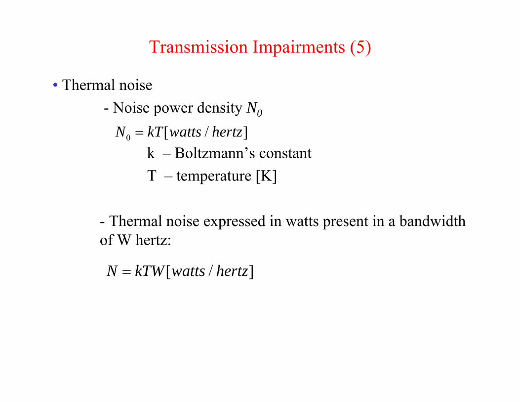
Transmission Impairments (5)
• Thermal noise- Noise power density N0
k – Boltzmann’s constantT – temperature [K]
- Thermal noise expressed in watts present in a bandwidth of W hertz:
0 [ / ]N kT watts hertz=
[ / ]N kTW watts hertz=

Transmission Impairments (6)• Intermodulation noise
- effect: produces signals at a frequency that is the sum or difference of the two original frequencies or multiple of those frequencies;- produced by some nonlinearity in the transmitter, receiver or transmission system;
• Crosstalk (diafonia)- unwanted coupling between signals path;
• Impulse noise- a minor annoyance for analog signal- the primary source of error in digital data communication

Guided Transmission Data
• Twisted Pair• Coaxial Cable• Fiber Optics

Twisted Pair
(a) Category 3 UTP.(b) Category 5 UTP.

Coaxial Cable
A coaxial cable.
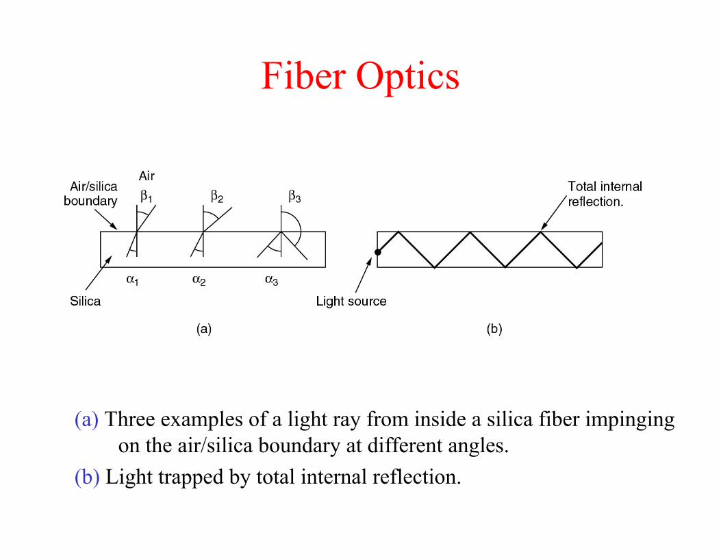
Fiber Optics
(a) Three examples of a light ray from inside a silica fiber impinging on the air/silica boundary at different angles.
(b) Light trapped by total internal reflection.

Fiber Cables
(a) Side view of a single fiber.(b) End view of a sheath with three fibers.

Fiber Cables (2)
A comparison of semiconductor diodes and LEDs as light sources.

Wireless Transmission
• The Electromagnetic Spectrum• Radio Transmission• Microwave Transmission• Infrared and Millimeter Waves• Lightwave Transmission
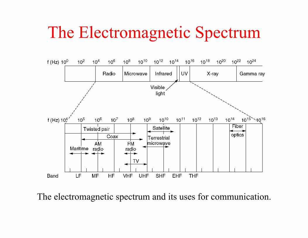
The Electromagnetic Spectrum
The electromagnetic spectrum and its uses for communication.

Public Switched Telephone System
• The Local Loops• The Trunks • The Switches

Structure of the Telephone System
A typical circuit route for a medium-distance call.

Major Components of the Telephone System
• Local loopsAnalog twisted pairs going to houses and businesses
• TrunksDigital fiber optics connecting the switching offices
• Switching officesWhere calls are moved from one trunk to another

The Local Loop
The use of both analog and digital transmissions for a computer to computer call. Conversion is done by the modems and codecs.

Circuit Switching
(a) Circuit switching.(b) Packet switching.

Packet Switching
• PS is more fault tolerant• PS does not waste bandwidth and thus is more
efficient• PS uses store and forward transmission• CS is completely transparent
• The sender and receiver can use any bit rate format and framing method. The carrier does not know or care
• With PS the carrier determines the basic parameters• The charging algorithm:
• CS: charging based on distance and time• PS: the volume of traffic

Circuit Switching – Packet Switching
(a) Circuit switching (b) Message switching (c) Packet switching
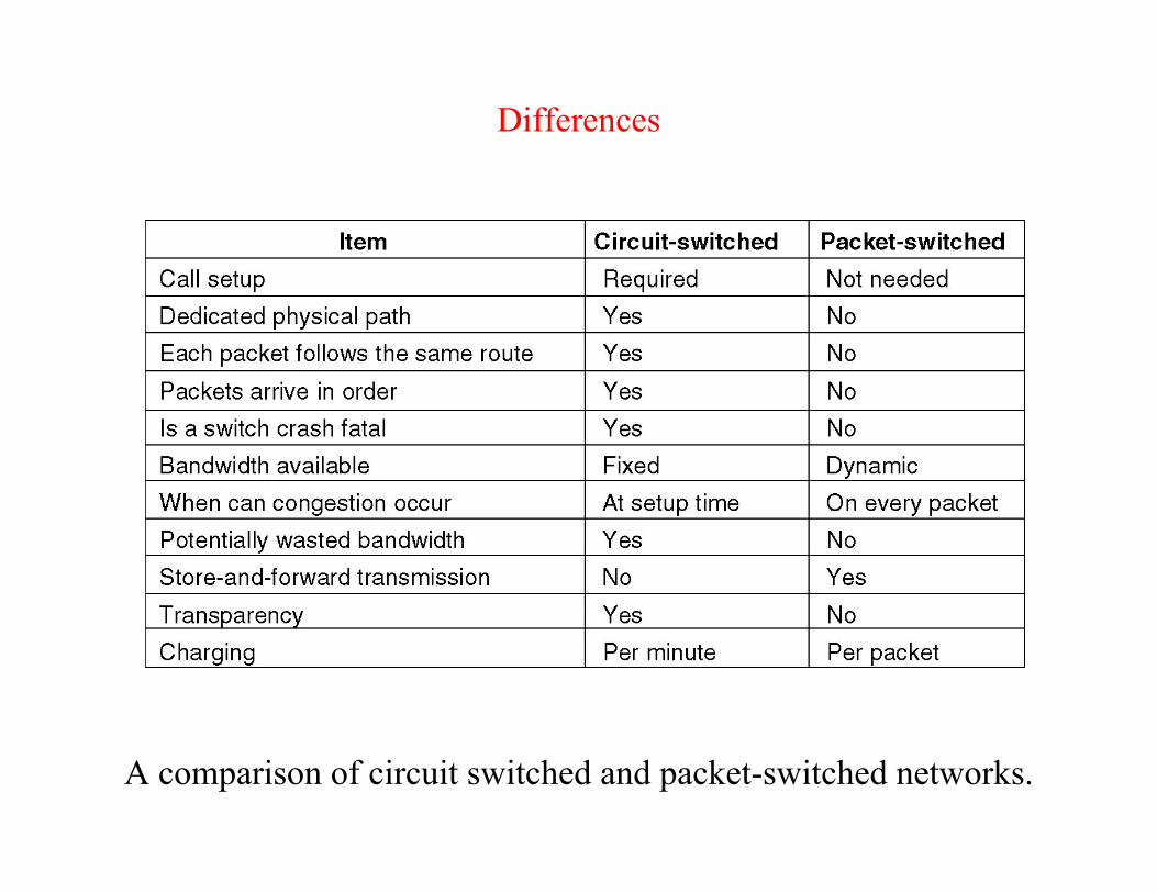
Differences
A comparison of circuit switched and packet-switched networks.

Mutiplexing
Statistical and nonstatistical multiplexingDef: multiplexing means putting several sources (together) on the
same link• Ways of multiplexing:
- Sharing time slots = temporal multiplexing- Sharing frequency bands = frequency multiplexing PS does not waste
bandwidth and thus is more efficient
• Temporal multiplexing is used in many telecommunications networks:
- In CS each source is allocated with one time slot;
• In statistical multiplexing data units are stamped with identifiers so that a source may send data at will

Multiplexing
Statistical multiplexing
PS: The bit rate of the output (4) is often less then the sum of the bit rates of all inputs (1 to 3); Special mechanisms, called congestion control are required to avoid that packet losses happen to frequently.
CS: The bit rate of the outgoing circuit (4) is at least equal to the sum of the incoming circuits bit rates (1 to 3); There is no loss of data.
T2
T3
T1
4