chapter 2 - encsusers.encs.concordia.ca/~mmedraj/tmg-books/solid state chemistry... · chapter 2...
TRANSCRIPT
31
Chapter 2
Determin ing the S t r u c t u r e of Solids
This c h a p t e r will p r e s e n t more advanced topics t h a n those of the f irs t
c h a p t e r in t e rms of d e t e r m i n i n g the s t r u c t u r e of solids. Consequent ly , you
will gain some knowledge of how one goes about d e t e r m i n i n g t he
s t r u c t u r e of a solid, even if you never have to do it.
2 .1 -SCIENTIFIC DETERMINATION OF THE STRUCTURE OF SOLIDS
In this section, we will p r e s e n t the basis developed to explain t h e
s t r u c t u r e of solids. Tha t is, the concep t s tha t were per fec ted in order to
accura te ly descr ibe how a toms or ions fit toge ther to form a solid phase .
This work was accompl i shed by m a n y pr ior worke r s who es tab l i shed t he
ra t ionale used to define the s t r u c t u r e of a symmet r i ca l solid. As you will
recall, we said tha t the basic difference be tween a gas, l iquid and tha t of a
solid lay in the o rde r l iness of the solid, c o m p a r e d to the o ther p h a s e s of
the same mater ia l .
We have a l ready ind ica ted tha t solids can have several forms or
symmet r i e s . To e lucidate the s t r u c t u r e of solids in more detail, at leas t
th ree pos tu la tes apply:
First , the format ion of a solid resu l t s from a symmet r i ca l "stacking" of
a toms to nea r infinity from a toms or molecu les with spac ings is m u c h
smal le r t h a n those found in the liquid or gaseous s tate .
Secondly , if we wish to gain an ins ight into how these a toms are a r r a n g e d
in the solid, we need to d e t e r m i n e wha t k ind of p a t t e r n they form whi le
in close proximi ty .
Thi rd ly , we can then re la te our p a t t e r n to o the r
define the s y m m e t r y of solids in genera l .
s t r u c t u r e s and thus
One way to approach a solution of the last two pos tu la tes is to define the
32
s t ruc tu re of any given solid in t e rms of its la t t ice poin ts , What this m e a n s
is tha t by subs t i tu t ing a point for each atom(ion) compos ing the s t ruc tu re ,
we find tha t these points cons t i tu te a lat t icework, i.e.- t h r e e - d i m e n s i o n a l
solid, having cer ta in symmet r i e s (Examples of the symmet r i e s to w h i c h
we refer are given in 1.3.2. of Chapte r 1).
A lattice is not a s t ruc tu re per se. A lat t ice is d e f i n e d as a s e t of t h r e e -
d i m e n s i o n a l points , having a cer ta in symmet ry . These points may, or may
not, be totally occupied by the a toms compos ing the s t ruc ture . Consider a
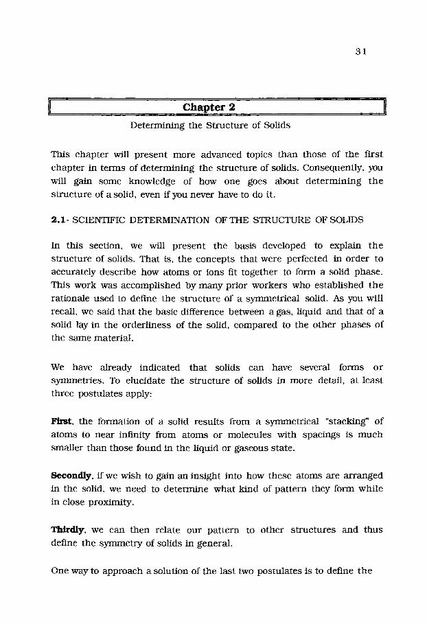
cubic s t ruc tu re such as tha t given in the following diagram:
Here, we have a set of points occupied by a toms (ions) a r ranged in a
s imple th ree -d imens iona l cubic pa t te rn . The lattice d i r e c t i o n s are
defined, by c o n v e n t i o n , as x , y & z. Note tha t there are eight (8) cubes in
our example .
In order to fur ther define our cubic pa t tern , we need to analyze bo th the
smal les t Unit and how it fits into the lattice. We call the smal les t Unit a
"unit-cell" and find tha t t he uni t -ce l l is the smal les t cube in the diagram.

33
We also need to define how large the uni t -ce l l is in t e r m s of bo th t h e
l eng th of i ts s ides and its vo lume. We do so by def ining the un i t - ce l l
d i rec t ions in t e r m s of its "lattice uni t -vec tors" . Tha t is, we define it in
t e r m s of the x, y, & z d i rec t ions of the un i t cell wi th specific v e c t o r s
having d i r ec t ions c o r r e s p o n d i n g to:
X ~ X
Z-~ ~
with the l eng th of each un i t -vec to r be ing equal to 1.0. (Our no ta t i on for a v e c t o r h e n c e f o r t h is a le t te r w h i c h is "outlined", e.g.- ~ is def ined here as
the uni t -ce l l vec tor in the "x" direct ion) . As you probab ly r e m e m b e r , a
"vector" is specif ied as a line wh ich has bo th d i rec t ion a n d d u r a t i o n f rom a
given po in t .
We can now define a set of vec tors cal led " t rans la t ion" vectors , i.e.- a , ~,
and ~ in t e r m s of the following:
2 .1 .2 . - a. = a x ~ + a y :y + a z g
b = b x z +t~]] +bz~
= Cx :~ + Cy ] + Cz
Here, the a , b, a n d ~ vec tors are now def ined in t e r m s of the a, b, and c
lat t ice c o n s t a n t s in each of the x, y, and z d i r ec t ions of 2.1.1. , w h e r e a, b,
and c are lat t ice cons t an t s . They are real n u m b e r s c o r r e s p o n d i n g to
~ n g s t r o m (A) d i s t ance uni t s , i.e.- 10- 8 cm.
Note t ha t we now have: a as a vec tor in t e r m s of x, y and z vec tors as a
func t ion of the lat t ice d i s t ances in the th ree d i rec t ions , ax, ay & a z .
Here, a = ax, ay & az, i .e.- a is c o m p o s e d of c o m p o n e n t s in each of t h e
th ree d i r e c t i o n s . The s a m e holds for b, and ~ vec to r s .

34
In general , we use only the lat t ice c o n s t a n t s to define the solid s t r u c t u r e
(unless we are a t t e m p t i n g to d e t e r m i n e its synm~etry). We can t h e n
define a s t r u c t u r e factor k n o w n as the t r ans l a t i on vector . It is a e l e m e n t
re la ted to the un i t cell and def ines the basic un i t of the s t ruc tu re . We wil l call it ~ . It is def ined accord ing to the following equa t ion :
2 .1 .3 . - = n l & + n2 5 + n3
w h e r e n l , n2 , and n3 are i n t e r c e p t s of the un i t -vec tors , ~ , y , a , on
the x, y, & z - d i rec t ions in the latt ice, respect ively . The un i t cel l vohxme
is t h e n def ined as:
2 .1.4.- V = { ~ - ] x a } (This is a " d o t - c r o s s " vec tor p r o d u c t ) .
Vector no ta t ion is be ing u s e d here because th is is the eas ies t way to
define the unit-cel l . The r ea son for us ing bo th un i t la t t ice vec tors and
t r ans l a t i on vec tors lies in the fact t ha t we can now specify un i t - ce l l
p a r a m e t e r s in t e r m s of a, b, and c (which are the i n t e r c e p t s of t h e
t r ans l a t i on vec tors on the lattice). These ceil p a r a m e t e r s are very useful
s ince they specify the actual l eng th and size of the un i t cell, usually in A.,
as we shall see.
Al though the cubic s t r u c t u r e looks like the s imples t one of those poss ib le ,
it actual ly is the m o s t c o m p l i c a t e d in t e r m s of symmet ry . What th is m e a n s
is t ha t we can "spin" the lat t ice by ho ld ing it at a ce r ta in po in t and
ro ta t ing it a r o u n d th is axis whi le still m a i n t a i n i n g the s a m e a r r a n g e m e n t
of a t oms in space. (Take a cube and do th is for yourself). The cubic l a t t i ce
gives rise to a g rea t m a n y s y m m e t r y e l e m e n t s in c o n t r a s t to less
synm~etr ical la t t ices (As we will see, if the lat t ice is e longa ted and
d i s to r t ed f rom cubic, some of these synm~etry e l e m e n t s do n o t arise) .
In 1895 , R6n tgen e x p e r i m e n t a l l y d i scovered "x-rays" and p r o d u c e d t h e
first p i c tu re of the b o n e s of the h u m a n hand . This was followed by w o r k by
von Laue in 1912 who s h o w e d tha t solid crys ta ls could act as d i f f rac t ion
g ra t ings to form s y m m e t r i c a l p a t t e r n s of "dots" w h o s e a r r a n g e m e n t
d e p e n d e d u p o n how the a t o m s were a r r a n g e d in the solid. It was soon

35
real ized tha t the a toms formed "planes" wi th in the solid. In 1913, Si r
William Henry Bragg and his son, William Lawrence Bragg, analyzed t h e
m a n n e r in which such x-rays were ref lected by p lanes of a toms in t he
solid. They showed tha t these ref lect ions would be mos t in tense at c e r t a i n
angles, and tha t the values would depend upon the d i s tance be tween t he
p lanes of a toms in the crysta l and upon the wavelength of the x-ray. Th i s
r e su l t ed in the Bragg equat ion:
2 .1 .5 . - n~. = 2d sin 0
where d is the d i s tance in a n g s t r o m s (A = 10 -8 cm) be tween p lanes and 0
is the angle in degrees of the reflection. In Bragg's x- ray diffract ion
equat ion, i.e.- the a n g l e , 0 , is actually the angle be tween a given p lane of
a toms in the s t r u c t u r e and the lmth of the x-ray beam. The unit , "d", is
defined as the d i s tance be tween p lanes of the lat t ice and k is t he
wavelength of the radiat ion. It w a s Georges Friedel who in 1913
d e t e r m i n e d tha t the in tens i t ies of ref lect ions of x-rays from these p lanes
in the solid could be used to d e t e r m i n e the s y m m e t r y of the solid. Thus ,
by convent ion, we usually define planes, not points , in the lat t ice.
We have i n t roduced the t e r m "symmetry" in the solid. Let us now e x a m i n e
exact ly w h a t is m e a n t by tha t term. To i l lus t ra te this concept , e x a m i n e
the s y m m e t r y e l emen t s of our cube, given in the follovcing diagram, given
on the next page as 2 .1 .6 .
In this case, we can show tha t the p lanes of the cubic latt ice are de f ined
by moving various d i s tances in the latt ice from the origin. What is m e a n t
by this te rminology is tha t as we move from the (0,0,0) origin jus t 1 .00
uni t -cel l d i s tance in the x" d i rec t ion to the (1,0,0) point in the cubic lattice, we have defined the {100} plane (Note tha t ,are are us ing the n l
i n t e rcep t of the uni t -cel l ) .
In a like m a n n e r , if we move in the "y" di rect ion a d i s tance of jus t 1 unit-
cell, we have defined the {010} plane. Using the the "z" d i rec t ions gets us
a set of one -d imens iona l p lanes (See line A in 2 .1 .6 . ) .

36
By moving I uni t -cel l d i s tance in the bo th the x- and y-di rec t ions , t he
{110) has been defined, etc. (Line B a b o v e - n o t e tha t we have no t
i l lus t ra ted the {101} plane). Moving 1 uni t -cel l in all th ree d i rec t ions t h e n
gives us the {111} plane. In a l i ke m a n n e r , we can obta in the {200}, {020}

37
and {002} planes . A set of p lanes such as the {003} and {004} ser ies are
not as common , bu t do exist in some solids. Also shown are the ro ta t iona l
axes of the cubic lattice, shown as the diad, t r iad and t e t r ad axes. "What
this m e a n s is ff ,are spin the cube on its face, we use the t e t r ad axis to
d e t e r m i n e tha t it t akes a total of 4 t u r n s to br ing any specific co rne r b a c k
to its original posit ion. Likewise, the t r iad axis uses the c o r n e r of the cube
where the latt ice is moved a total of th ree t imes, and the diad axis
employs the diagonal a c r o s s t h e cube to pe r fo rm the synm~ehur opera t ion .
Thus , the p lanes of the lat t ice are found to be i m p o r t a n t and can be
defined by moving along one or more of the lat t ice d i rec t ions of the uni t -
cell to define them. Also i m p o r t a n t are the s y m m e t r y opera t ions tha t can
be pe r fo rmed wi th in the unit-cell , as we have i l lus t ra ted in the p r e c e d i n g
diagram. These give rise to a total of 14 different la t t ices as we will show
below. But first, let us confine our d iscuss ion to jus t the s imple cubic
lat t ice.
It t u r n s out tha t the m e t h o d u sed to decr ibe the p lanes given above for
the cubic latt ice can also be used to define the p lanes of all of the k n o w n
latt ices, by use of the so-cal led "Miller Indices", which are r e p r e s e n t e d by:
2 .1 .7 . - { h , k , l }
The way tha t Miller Indices arose can be u n d e r s t o o d by cons ide r ing t h e
h is tory of crysta l s t r u c t u r e work, accompl i shed by m a n y inves t iga tors .
In 1921, E~wald developed a m e t h o d of ca lcula t ing the s u m s of diffract ion
in tens i t ies from different p lanes in the latt ice by cons ide r ing wha t is
called the "Reciprocal Lattice". The rec iproca l lat t ice is ob ta ined by
drawing p e r p e n d i c u l a r s to each p lane in the lattice, so tha t the axes of t h e
rec iprocal latt ice are p e r p e n d i c u l a r to those of the crys ta l lattice. This has
the resu l t t ha t the p lanes of the rec iprocal lat t ice are at r ight angles (90 ~ )
to the real p lanes in the unit-cell . For our cubic lattice, the r e c i p r o c a l
latt ice -would look as shown in the following diagram, given as 2.1.8 on t he
next page.

38
In this diagram, a series of hexagon- shaped planes are shown which are
or thogonal , or 90 degrees, to each of the corners of the cubic cell. Each
plane connec t s to ano the r plane (here shown as a rectangle) on each face
of the unit-ceU. Thus, the faces of the lattice unit-cell and those of the
reciprocal unit-cell can be seen to lie on the same plane while those at
the corners lie at r ight angles to the co rne r s .
The not ion of a reciprocal lattice arose from Ewald who used a sphe re to
r ep re sen t how the x-rays in terac t with any given lattice plane in t h r e e
d imens iona l space. He employed wha t is now called the Ewald Sphere to
show how reciprocal space could be utilized to r ep re sen t diffractions of x-
rays by lattice planes. Ewald originally r e w r o t e the Bragg equat ion as:
2 .1 .9 . - sin 0 = n k/ = 1 / d {hkl}
2d {hkl} 2/X
Using this equation, Ewald applied it to the case of the diffraction s p h e r e
which we show in the following d iagram as 2.1.10. on the next page.
S tudy this d iagram carefully. In this case, the x-ray b e a m en te rs the
sphere en ters from the left and encoun te r s a lattice plane, L. It is t h e n
diffracted by the angle 20 to the point on the sphere , P, where it

39
is reg is te red as a diffaction point on the reciprocal lattice. The d i s t ance be tween planes in the reciprocal lattice is given as 1/dhkl which is readi ly
obta ined from the diagram. It is for these reasons , we can use the Miller
Indices to indicate p lanes in the real latt ice.
The reciprocal lattice is useful in defining some of the e l ec t ron ic
p roper t i es of solids. Tha t is, w h e n we have a s emi -conduc to r (or even a
conduc to r like a metal), we find tha t the e lec t rons are confined in a band,
defined by the reciprocal lattice. This has impor t an t effects upon the
conduct ivi ty of any solid and is known as the "oand theory" of solids. It
t u rn s out tha t the reciprocal lattice is also the site of the Brfllouin zones,
i.e.- the "allowed" electron energy bands in the solid. How this o r ig ina tes
is explained as follows.
The free electron res ides in a quant ized energy well, defined by k (in
wave-numbers) . This resul t can be derived from the Schroed inge r wave-
equation. However, in the p resence of a periodic array of e l e c t r o m a g n e t i c
potent ia ls ar is ing from the a toms conf ined in a crystal l ine lattice, t he
energies of the e lec t rons f rom all of the a toms are severely l imited in
orbit and are res t r i c ted to specific allowed energy bands. Th i s po ten t ia l
or iginates from at t rac t ion and repuls ion of the e lect ron clouds from the
periodic array of a toms in the s t ruc ture . Solut ions to this p rob lem w e r e

4 0
m a d e by B loch in 1 9 3 0 w h o s h o w e d t h e y h a d t h e f o r m (for a o n e -
d i m e n s i o n a l l a t t i ce ) .
2 . 1 . 1 1 . - = e ikx u ( x ) - o n e d i m e n s i o n a l
~k (a) = e ika u k (X) - t h r e e d i m e n s i o n a l
w h e r e k is t h e w a v e n u m b e r of t h e a l l owed b a n d as m o d i f i e d by t h e
la t t ice , a m a y be x, y or z, a n d uk (x) is a p e r i o d i c a l f u n c t i o n w i t h t h e s a m e
p e r i o d i c i t y as t h e p o t e n t i a l . O n e r e p r e s e n t a t i o n is s h o w n in t h e fo l lowing:

41
We have shown the least compl ica ted one which t u r n s out to be t h e
s imple cubic lattice. Such b a n d s are called "BriUuoin" zones a n d , as we
have said, are the allowed energy b a n d s of e lec t rons in any given
crystal l ine lat t t ice. A n u m b e r of me ta l s and s imple c o m p o u n d s have b e e n
s tud ied and thei r Brilluoin s t r u c t u r e de t e rmined . However, w h e n one
gives a r e p r e s e n t a t i o n of the energy b a n d s in a solid, a "band-model" is
usually p r e sen t ed . The following d iagram shows th ree b a n d mode l s :
2 .1 .13.- Energy Band Models
In the solid, e lec t rons res ide in the valence band but can be exci ted in to
the conduc t ion b a n d by absorp t ion of energy. The energy gap of various
solids d e p e n d s upon the na tu r e of the a toms compr i s ing the solid. Semi-
conduc to r s have a r a t h e r na r row energy gap (forbidden zone) vchereas
tha t of insu la tors is wide (metals have little or no gap). Note tha t e n e r g y
levels of the a toms "A" are shown in the valence band. These will vary
depend ing upon the na tu re a toms p resen t . We will not delve fu r the r into
this aspec t here s ince it is the subject of more advanced s tudies of
e lect ronic and optical mate r ia l s .

4 2
R e t u r n i n g to the uni t -cel l , we can also uti l ize the vec tor m e t h o d to de r ive
the origin of the Miller Indices . The gene ra l equa t ion for a p l ane in t h e
la t t ice is:
2 . 1 . 1 4 . - ~ x,y,z o ~ = d
w h e r e ~ x,y,z is the la t t ice un i t vec tor in any of the t h r e e d i m e n s i o n s , ~ is
the gene ra l vec to r of the la t t ice f rom the origin a n d d is, of course , t h e
d i s t a n c e b e t w e e n p l anes of the la t t ice f rom the origin. A b e t t e r
p e r s p e c t i v e is s h o w n in the following d i ag ram:
If ~ x,y,z is n o r m a l to the real la t t ice p lane (as in the r ec ip roca l Latt ice},
we can define the x, y a n d z d i r ec t ions of the un i t cell in t e r m s of the un i t
cell vec tors and the c o r r e s p o n d i n g i n t e r c e p t s of the r ec ip roca l la t t ice ,
i.e.- h, k, a n d 1:
2 . 1 . 1 6 . - x = ~ / h y = ] / k z = a /1
Then , the l a t t i ce un i t vec tor will be:
2 .1 .17 . - ~ h,k,1 = 1/ {h 2 + k 2 + 12} 1/2 {11 ~, + k :~ + 1 ~}
w h e r e we have c o n v e r t e d the x, y and z d i r ec t ions into i n t e r c e p t s of t h e
r ec ip roca l la t t ice cell. As we shal l see, th i s equa t ion is also useful in
der iv ing e q u a t i o n s desc r ib ing s y n m l e t r y o p e r a t i o n s a n d p lane s p a c i n g s of
the real l a t t i ce .

43
To show tha t the above d i scuss ion is t rue , c o n s i d e r the following. Let us
set up a p lane of a cubic lat t ice as s h o w n in the following d iagram:
In th is case, we have s h o w n a {310} p lane of a cubic latt ice. Note t ha t w e
move 3 s t eps of "a" in the x -d i r ec t ion and one in the "y" d i rec t ion to
define th is plane. Since a p lane is two-d imens iona l , th is r e p r e s e n t a t i o n is
accura te . The equa t ion of any one of the e l e m e n t s of th is p lane is thus:
2 .1 .19 . - a = 3x + y
and if we h a d b or c (both of w h i c h equal "a" in a cubic lattice), we cou ld
t hen use a , b, & c to r e p r e s e n t the l eng ths of the s ides of the un i t -ce l l
w h i c h in t u r n define the p l anes w i t h i n t h e u n i t ceil. For the cubic la t t ice ,
t h e n we have:
2 . 1 . 2 0 . - d = 1 / (h 2 + k 2 + 1 2)1/2 . [ h ~ + h : y + h ~ ]
Note t h a t j u s t t h r ee po in t s have been u s e d to define our p lane (see
2.1.6.) . The or iginal def ini t ion was given by Whewel l in 1825 and by
G r a s s m a n in 1829, bu t was popu la r i zed by Miller in 1839. Since t h r e e
po in t s of a lat t ice can be u s e d to define a plane, it is obvious t ha t s u c h

4 4
p l anes can be def ined by u s ing only t h r e e po in t s in space , i.e.- a , b & c,
to c h a r a c t e r i z e the se t of p l anes wi th in the la t t ice . Miller Ind ices are t h e
r ec ip roca l s of the i n t e r c e p t s , a , b & c, of the c h o s e n p lane on the x , y , z - d i r ec t ions in the la t t ice (and re la te to the n l, n2 and n3 i n t e r c e p t s
w h i c h we u s e d in ou r def in i t ion of the uni t -cel l ) . How they are u s e d is
s h o w n in the following table:
2 .1 .21 . - Poin ts on the Lat t ice a n d C o r r e s p o n d i n g Miller I n d i c e s
a , b , c MILLER INDICES
(1, 0, O) {100}
(1 /2 , 0, 0 ) {200}
(o , ~/2, o) {o2o} (0, O, 1 /2 ) {002}
Here, we have def ined the s u m tota l of the i n t e r c e p t s in t e r m s of the uni t -
cell d i s t a n c e be ing se t equa l to 1.00, i .e.-
2 . 1 . 2 2 . - a / ( 1 / h ) + b / ( 1 / k ) + c / ( 1 / k ) = 1
Thus , t h e s e i n t e r c e p t s are given in t e r m s of the ac tua l un i t -ce l l l e n g t h
found for the specif ic s t r u c t u r e , a n d not the la t t ice itself. The Mi l le r
Ind ices are t h u s the ind ices of a stack of planes wi th in the la t t ice . P l anes
are i m p o r t a n t in sol ids because , as we will see, t hey are u s e d to loca te
a t o m pos i t ions wi th in the la t t ice s t r u c t u r e .
The Final f ac to r to c o n s i d e r in our s t u d y of how to def ine t h e
s t r u c t u r e of sol ids is t h a t of the ang le b e t w e e n the x, y, a n d z d i r e c t i o n s
in the la t t ice . In our e x a m p l e so far, all of the angles were 90 ~ in all
d i r ec t ions (also cal led "orthogonal") . If the angles are not 90 ~ t h e n w e
have add i t iona l la t t ices to define. For a given uni t -ce l l def ined by the uni t -
cell l eng ths , a, b & c, the c o r r e s p o n d i n g angles have b e e n def ined as:
2 .1 .23 . - Nota t ion Used for Del 'ming Angles in the Solid La t t i ce
a = 2 ~ / n I
~ = 2 n / n 2
7 = 2 ~ / n ~

45
w h e r e ~ is the angle in the x-d i rec t ion , ~ is in the '~ d i rec t ion , etc. T h e
i n t e r c e p t s are those of the lat t ice and not of the uni t -cel l . Note t ha t c~ , ~,
Y = 90 o for the cubic lat t ice as given above as 2 .1 .1 .
This c o m p l e t e s ou r d i scuss ion of the basis and fac tors deve loped by pas t
inves t iga tors to desc r ibe and concep tu l i ze the s t r u c t u r e of solids. You wil l
note t ha t we have no t yet fully de sc r ibed the s y m m e t r y factor of solids.
The r ea son for th is is t ha t we use s y m m e t r y factors to cha rac t e r i ze sol id
s t r u c t u r e w i t h o u t r e so r t i ng to the theore t i ca l bas is of s t r u c t u r e
d e t e r m i n a t i o n . Tha t is, we have a s t a n d a r d m e t h o d for ca tegor iz ing sol id
s t r uc tu r e s . We say t ha t salt, NaC1, is cubic. Tha t is, the Na § ion a n d the CI
ion are a l t e rna te ly a r r a n g e d in a c l o se -packed cubic s t r uc tu r e . The n e x t
sec t ion now inves t iga tes these s t r u c t u r e p ro toco l s .
2 .2 . - Solid S ta te S t r u c t u r e Conven t ions and P ro toco l s
We have a l ready d i su s sed s t r u c t u r e factors and s y n m l e t r y as they re la te to
the p r o b l e m of def ining a cubic uni t -ce l l and find t ha t still a n o t h e r fac tor
exis ts if one is to comple t e ly define crys ta l s t r u c t u r e of solids. This t u r n s
ou t to be tha t of the individual a r r a n g e m e n t of a t o m s wi th in the uni t -ce l l .
This t h e n gives us a total of t h ree (3) fac tors are n e e d e d to define a given
latt ice. These can be s t ipu la t ed as follows:
2 .2 .1 . - Fac to rs Needed to Fully Define a Crystal Lat t ice
I - uni t -ce l l a x e s , i n t e r c e p t s and angles
II - ro ta t iona l s y m m e t r y
III - localized space g roup s y m m e t r y
In the first F a c t o r , if the cell l eng ths are no t equal , i.e. a , b , c, w e
no longer have a cubic lat t ice, bu t some o t h e r type. And if the angles are
no longer 90 ~ i.e.- ~ , b , g , t h e n we have a change in the lat t ice type
as well. Addit ionally, we can have the s i tua t ion w h e r e r = ~ , y , ~ , ~ = y
a n d ~ , ~ , y , or a l ternat ively, a , ~ = Y, a = [3 , Y a n d a , ~ , y . T h e
n u m b e r of c o m b i n a t i o n s t h a t we can m a k e f rom these 3 - l eng ths and 3-
angles is seven (7) a n d these define the 7 un ique lat t ice s t r u c t u r e s w h i c h
46
are called BRAVAIS LATFICES after the or iginator of the concept . T h e s e
have been given specific names:
2 .2 .2 . - CUBIC
HEXAGONAL
T ~ G O N A L
TRIGONAL
ORTHORHOMBIC
MONOCLINIC
TRICLINIC
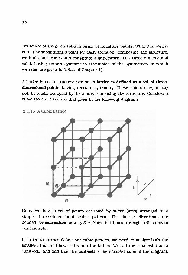
We can therefore ar range the seven (7) sys tems into a h ie ra rchy based on
symmetry , as shown in the following d iag ram
2.2 .3 . -
IHierarchy of Crystal systems I
1 c~bic !
I Hexag~ j
I Orthorhomb, ci IT~'g ~ !
I M~176 I I
I
I T r ic l in ic I Each System is a Special Case of Those Above It
The lattice with the h ighes t sy m m et ry is l isted at the top, with the least
symmetr ica l lattice being shown at the bot tom. Each of these seven
lattices may have sublatt ices, the total being 14.
The following diagram, given on the next page as 2.2.4., shows the
s y m m e t r y of these 14 Bravais space latt ices in t e rms of the seven crystal
sys tems given in 2.2.3. The specific res t r ic t ions are l isted in Table 2-1 on
the following page along with the relat ion be tween axes and angles

47

4 8
a s soc i a t ed wi th each s t r u c t u r e . C o n t r a s t b o t h the da t a in Table 2-1 and
the d i a g r a m s in 2 .2 .4 . in o rde r to get a c lear no t ion of the s y m m e t r y
fac tors involved in the 14 Bravais l a t t i ces .
TABLE 2- I
THE FOURTEEN (14) BRAVAIS LATYICES IN THREE DIMENSIONS.
NUMBER OF
.LATTICES
SYSTEM IN SYSTEM
R E S T R I C T I O N S
ON UNIT CEIL
LATI'ICE SYMBOLS AXES AND ANGLES
Cubic
Hexagona l
T e t r a g o n a l
T r i g o n a l
O r t h o r h o m b i c
Monoc l in i c
T r i c l i n i c
P (p r imi t i ve )
I ( b o d y - c e n t e r e d )
F(face - c e n t e r e d )
R
P
C
I
F
P
C
a = b = c
=13 = "?' = 9 0 ~
a = b ~ c (~ = ~ = ~
((~ = ~ = 9 0 ~
(y = 120 o)
a = b r c
=1~ = y = 9 0 ~
a = b = c
(~ = ~ = 9 0 ~
90 o> ~/ < 120 o
a ~ b , c
a = ~=~, = 9 0 ~
a s b ~ c
a = 7 = 9 0 ~
a , b # c
The fac tors given in b o t h 2.2.4. a n d Table 2-1 ar ise due to the un i t - ce l l
axes, i n t e r c e p t s a n d angles involved for a given c rys ta l la t t ice s t r u c t u r e .
Also given are the la t t ice symbols w h i c h are genera l ly used . The axes and
angles given for each s y s t e m are the r e s t r i c t i o n s on the un i t cell to m a k e
49
it conform to the par t icular type of lattice. They complete ly define tha t
s t ruc tu re except for the symmet ry .
These 14 Bravais Latt ices are un ique in themselves . If we ar range the
crystal sys t ems in t e rms of symmetry , the cube has the h ighes t s y r m n e t r y
and the triclinic lattice, the lowest symmetry , as we showed above. T h e
same h ie ra rchy is ma in t a ined in 2.2.4. as in Table 2-1. The symbols u sed
by convent ion in 2.2.4. to denote the type of lattice p r e sen t are
P = Primi t ive
I = Invers ion (or b o d y - c e n t e r e d )
F = F a c e - c e n t e r e d
What tl~As m e a n s is tha t the primitive lattice is composed of points at t he
corners of the lattice, whereas the invers ion lattice has an addit ional po in t
at the center of the lattice, i.e.- "body-centered". Face-cen te red has
points in the middle of each face of the lattice in addi t ion to those at t he
corners of the latt ice.
If we now apply ro ta t io~f l s y m m e t r y (Factor II given in 2.2.1) to the 14
Bravais lattices, we obtain the 32 Poin t -Groups which have the factor of
sy mme t ry imposed upon the 14 Bravais lattices. The symmet ry e l e m e n t s
tha t have been used are:
2 .2 .5 . - Rotat ion axes Plane sy m m et ry < hor izonta l
ver t ical
Inversion s y m m e t r y (mi r ro r )
We have already i l lus t ra ted ro ta t ion axes in 2.1.6. Plane s y m m e t r y involves
s y m m e t r y such as tha t of the hexagonal faces given above in 2.2.5. We will
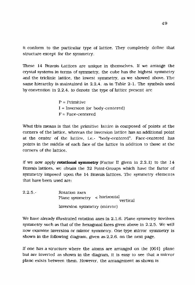
now examine invers ion or mi r ro r symmetry . One type mi r ror symmet ry is
shown in the following diagram, given as 2.2.6. on the next page.
If one has a s t ruc tu re where the a toms are a r ranged on the {001} p lane
but are inver ted as shown in the diagram, it is easy to see tha t a m i r r o r
plane exists be tween them. However, the a r r a n g e m e n t as shown is

50
2 .2 .6 . -
l lnversion Mirror Symmetry I
inverted. It is this k ind of rota t ion and inversion tha t will be seen to be
vital in fully descr ib ing the s t ruc tu re of solids.
We have already descr ibed crystal s t ruc tu re s in t e rms of p ropaga t ion
units , i.e.- t ranslat ion, in which the crystal is composed of a small n u m b e r
of individual a toms a r ranged in a uni t which is p ro l i f e ra ted to form the
solid. Each assembly of a toms, i.e.- p ropagat ion units , is re la ted to any
o ther by one of four s imple operat ions . These are:
2.2.7.- The Four Symmetry_ Opera t ions
Transla t ion, i.e.- from one plane to ano the r
Rotat ion about an axis of the crystal
Reflection across a p lane
Inversion th rough a po in t
These are the four ma in opera t ions requi red to define the s y m m e t r y of a
crystal s t ruc ture . The mos t impor t an t is tha t of t rans la t ion since each of
the o ther p rocedures , called sy m m et ry operat ions , m u s t be cons i s t an t
with the t rans la t ion opera t ion in the crystal s t ruc ture . Thus, the ro ta t ion
opera t ion m u s t be t h rough an angle of 2n / n, where n = 1, 2, 3, 4 or 6.

51
Note tha t we have a l ready shown tha t the cubic lat t ice can be ro ta ted only
in this m a n n e r , except ing six. We find tha t the n u m b e r 6 comes from the
hexagonal lat t ice itself where the a r r a n g e m e n t of a toms is obvious (see
2.2.4.). Each of the opera t ions involving crysta l a ssembly un i t s c rea tes a
special group:
Trans la t iona l symanetry opera t ions gene ra t e the 14 Bravais la t t ices .
The rotational opera t ions gene ra t e a total of 32 Point Groups de r ived f rom
these s y m m e t r y opera t ions on the 14 Bravais la t t ices .
The reflections and inversions s y m m e t r y opera t ions genera te a total of
231 groups, called Space Groups which inc lude the 32 Point Groups.
In Point Groups, one point of the lat t ice r e m a i n s invar ient u n d e r
s y m m e t r y opera t ions , i.e.- there is no t rans la t ion involved. Space Groups
are s o - n a m e d because in each group all three- d imens iona l space r e m a i n s
invar ient u n d e r opera t ions of the group. Tha t is, they conta in t r ans la t ion
c o m p o n e n t s as well as the th ree s y m m e t r y opera t ions . "We will not dwel l
upon the 231 Space Groups since these re la te to d e t e r m i n i n g the exac t
s t r u c t u r e of the solid. However, we will show how the 32 Point Groups
relate to crysta l s t r u c t u r e of solids.
In 1890, Schoenflies fo rmula ted a group of symbols descr ib ing the various
ro ta t ions possible for Point Groups. These were rep laced in 1936 by t he
In te rna t iona l Symbols or H e r m a n n - M a u g u i n Symbols, s ince the po in t
group sys t em could not be ex t ended to descr ibe Space Groups. A
compar i son of the Point Group Symbols are given in the following Table,
given on the next page as Table 2.2. The a r r a n g e m e n t shown for
Schoenflies symbols in 2.2.8 on the next page is inver ted. It is this k ind of
ro ta t ion and invers ion tha t will be seen to be vital in i~dlly descr ib ing t he
s t r uc tu r e of solids. Subsc r ip t s in Table 2-2 are u sed to indica te the d e g r e e of the ro ta t ional axes p resen t , i.e.- C3 -- a three(3) fold ro ta t ional axis.
Horizontal synmle t ry is ind ica ted by "h" while vert ical s y m m e t r y = v.

52
Table 2.2. - C o m p a r i s o n of Schoenflies and In t e rna t i ona l S y m b o l s
crystaJ
N a m e
Cubic
Hexagonal
T e t r a g o n a l
T r igona l
O r t h o r h o m b i c
Monoc l in i c
S y s t e m
G e o m e t r y
a = b = c
r =7=90~
a = 1 3 * c
(~=13 = 9 0 ~ (7 = 120 o)
a = b , c
a = ~ = y = 90 ~
a = b = c
a = 13 = 90 ~
90 o > y < 120 ~
a~b~c
a= ~ = 7 = 90~
a s b * c
a=~ =90~ 7
a ~ b ~ c
,a ,* ~ ' 7
Tr i c l i n i c
Point
Schoenfl ies
T
0
T h
T d
Oh
C6 D6
C2h
C6v C3h
D3h
D6h
C4 D4
C4h C4v $4
D2d D4h
C3 D3
C3v C3i
D3d
&
D2 C2v D2h
C2
C3
C2h
C1
q , , , . . . . .
Group S y s t e m ,,
I n t e r n a t i o n a l i
23
4 3 2
m 3
4 3 m
m 3 m
6
6 2 2
6 / m
6 r a m
6 6 m 2 o r 6 2 m
6 / m
4
4 2 2
4 / m
4 m m
4 4 m 2 or 4 2 m
4 / m m m
32
3 m
3 & 3 2 1 m
2 2 2
m m 2
m m m
2
i n
2 / m
1
1
Bravais i i
Lat t i ce
P
I
F
P
C
F
P
C

53
In the Schoenflies notat ion, the e l emen t s defined a s -
2 .2 .8 . - C = ro ta t ion axis only
D = d ihedra l (rotat ion plus d ihedra l ro ta t ion axes)
I = invers ion s y m m e t r y
T --- t e t r a h e d r a l s y m m e t r y
0 - oc t ahed ra l s y m m e t r y
In the H e r m a n n - M a u g u i n Symbols , the s ame rota t ional axes are ind ica ted ,
plus any invers ion syrmnet ry tha t may be p resen t . The n u m b e r s ind ica te
the n u m b e r of ro ta t ions p resen t , m shows tha t a m i r ro r s y m m e t r y is
p r e s e n t and the invers ion s y m m e t r y is ind ica ted by a ba r over t h e , _ , - .
number , i.e.- 5 .
At this point, you m a y find tha t the subject of syrranetry in a crys ta l
s t r u c t u r e to be confusing. However, by s tudying the te rminology carefully
in Table 2-2, one can begin to sor t out the various la t t ice s t r u c t u r e s and
the symbols u sed to del ineate them. All of the crysta l sys t ems can be
desc r ibed by use of e i ther Schoenflies or H e r m a n n - M a u g u i n symbols,
coupled wi th the use of the p rope r geomet r ica l symbols .
In 1965, specific d iag rams were developed by Weinre ich to i l lus t ra te t he
32 po in t -g roup symmet r i e s . Appropr ia te Schoenflies symbols were also
given. These drawings are given on the following page as 2.2.10. If t hey
are examined closely, it becomes eas ier to assess and c o m p a r e t he
differences in s y m m e t r y opera t ions involved for each type of la t t ice
s t ruc tu re . As an example, cons ide r the following.
In the C l h point group, the re is a one-fold rotation axis p lus hor izonta l
syTmnetry (horizontal mirror) . Note also the difference be tween C l h and
C2h.
It is easy to see t ha t these point g roups are re la ted to one another , but tha t they specify qui te different ro ta t ional symmet r i e s . In con t ras t , C2 has
a 2-fold ro ta t ion axis bu t no hor izonta l s y m m e t r y (but C2h has hor izonta l
symmetry) . Cont ras t the C2v point g roup wi th vert ical s y m m e t r y to the C2

54

55
and C2h point groups . The D2h point group has a two-fold ro ta t ion axis, a
hor izontal mir ror , and 2 diad ro ta t ion axes. Compare also the Cv and D3v
point g roups and the C3h and D3h groups .
Now examine the s y m m e t r y e l emen t s for the cubic lattice. It is easy to
see tha t the n u m b e r of ro ta t ion e lements , plus hor izontal and ver t ica l
synmle t ry e l emen t s is quite high. This is the r ea son why the Cubic
S t r u c t u r e is p laced at the top of 2.2.3. Even though the lat t ice points of
2 .2 .1 . are decept ively s imple for the cubic s t ruc tu re , the s y m m e t r y
e l emen t s are no t
There is one o ther factor con t r ibu t ing to the overall s y m m e t r i e s of t h e
lat t ice s t ruc tu re . This factor involves the local s y m m e t r y of the a tomic
g roups which actually form the s t ruc tu re . Examples are the "sol id-s ta te bui lding blocks" given above, e.g.- the t e t r a h e d o n - the group, PO43" and
the oc t ahed ron - like group, NbO6-. It is easy to see tha t if a s t r u c t u r e is
composed of such bui lding blocks, they will impose a local s t ruc tu ra l
s y m m e t r y on the lattice, in addi t ion to the o ther s y m m e t r i e s a l ready
p r e s e n t .
The resu l t is tha t Factor III of 2 . 2 .6 . given above imposes f u r t h e r
s y m m e t r y res t r i c t ions on the 32 point g roups and we obtain a total of 231
space groups. We do not i n t end to delve fu r the r into this aspec t of la t t ice
con t r ibu t ions to crysta l s t r u c t u r e of solids, and the factors which cause
t h e m to vary in form. It is sufficient to know tha t they exist. Having
covered the essent ia l pa r t s of lat t ice s t ruc tu re , we will e lucidate how one
goes about d e t e r m i n i n g the s t r u c t u r e for a given solid.
2-3: HOW TO DETERMINE THE STRUCTURE OF COMPOUNDS
We wan t to review how one goes about actually d e t e r m i n i n g the s t r u c t u r e
of a given solid. There are two factors we need to cons ide r :
1) w h a t are the s teps r equ i red in actually d e t e r m i n i n g a s t r u c t u r e ?
2) w h a t k ind of in format ion is ob ta ined?

56
Since the crys ta l is a per iodic a r ray of a t o m s in wh ich the i n t e r a t o m i c
d i s t ances and i n t e r p l a n a r spac ings are of the s ame o rde r of m a g n i t u d e as the wave leng ths of the readi ly available x-rays, e.g.- the Ka rad ia t ions , we
can use a ta rge t of the x- ray tube c o m p o s e d of one of the heav ie r
e l ements . This gives r ise to cha rac t e r s i t i c monochromat ic r ad ia t ion
def ined by:
2 .3.1.- Mo = 0 .711 fi,- Cu = 1 .5418 ft,- a nd Cr = 2 .291 ft,.
A crys ta l the re fore acts as a t h r e e - d i m e n s i o n a l diffract ion g ra t ing for
these x-rays, and th ree equa t ions (the Laue equat ions) m u s t be sat isf ied if
the re is to be cons t ruc t ive i n t e r f e r ence of these m o n o c h r o m a t i c x-rays.
The Laue equa t ions to be employed are:
2 .3 .2 . - a(a-cto ) = h k b (~-fio) = k k c (7- ~/o ) = 1 k
w h e r e a, b and c are the r e p e a t d i s t ances of the lattice, a and ao (etc .) ,
are the d i rec t ion cos ines for the diffracted a nd inc iden t b e a m s
respect ively , and h, k, and 1 are in tegers def ining the o rde r of t h e
pa r t i cu la r diffracted beam. k is, obviously, the w a v e l e n g t h be ing di f f rac ted .
It was W. L. Bragg who showed tha t the above equa t ions are equiva len t to
the cond i t ion for ref lect ion of the x-rays by the p lane wi th indices h k l ,
namely:
2 .3 .3 . - n k = 2 d sin Ohkl
Here , 0 is the angle be tween the inc iden t (or ref lected) b e a m for t he
plane, hkl . Also, d is the p e r p e n d i c u l a r d i s t ance be tw e e n success ive
p lanes . If we wish to d e t e r m i n e the exact s t r u c t u r e of any given solid, we
need to follow the following s teps :
I. Obtain a sui table x- ray p a t t e r n us ing a single crystal of t he
mate r ia l .
2. De t e rmine the exact in tens i t i e s of the l ines or po in t s in t he
p a t t e r n by in t eg ra t ion of the dif f racted energy .

57
3. Calculate the values of d, the d i s tance be tween ad jacen t p lanes in
the crysta l lat t ice by us ing the Bragg Equat ion .
4 .De t e rmine the spac ings of the l ines in the pa t t e rn , and from t h e s e
the d imens ions of the uni t -cel l .
5. Scale our ca lu la ted in tens i t ies to our observed in tens i t ies by:
E Ic = E Io
and calculate a reliabili ty factor, called R, from: R = E (Io - Ic ) /Z Io
6. De te rmine the s t r u c t u r e factor, F(hkl) 2 for the p a t t e r n .
7. Refine the s t r u c t u r e factor unt i l it app roaches zero.
Nowadays, mos t of these s teps are done us ing a Compute r . The total
energy diffracted by {hkl} p lanes is p ropor t iona l to the squa re of t h e
s t r u c t u r e factor, viz-
2.3.4.- E (hkl) = F (hkl) 2
The s t r u c t u r e factor itself is exp re s sed as the s u m of energy diffracted, over one unit-cell , of the individual sca t t e r ing factors, fl, for a toms loca ted
at x, y and z. Having done this, we can then identify the exact locat ions of
the a toms (ions) wi th in the unit-cell , its po in t -g roup symmet ry , and
crysta l sys tem. This t hen comple tes our p ic ture of the s t r u c t u r e of t he
mater ia l .
However, one is usually more i n t e r e s t ed in identifying the na tu r e of t h e
c o m p o u n d by x- ray analysis and does not usually wish to identify t he
s t r u c t u r e in detail. To do this, we p roceed as follows. Firs t of all, we s ta r t
wi th La~O3 and/~d203. After fh-ing a 1:11 mix tu re of the two, we use an x-
ray diffraction i n s t r u m e n t to obta in a ser ies of diffraction l ines as d e p i c t e d
in the following diagram, given as 2.3.5. On the nex t page.
Because of the physical geomet ry of the x-ray diffraction g o n i o m e t e r
( ang le -measur ing device), one obta ins values of 20 directly. T h e
in tens i t ies are r ead from the diffraction char t , scaled to the mos t i n t e n s e
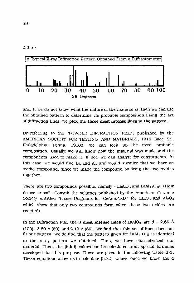
58
2 .3 .5 . -
I A Typical X-ray Diffraction Pattern Obtained From a Diffra~,. tometer]
0 I 0 20 30 40 50 60 70 80 90 100 :2 8 Degrees
line. If we do not know wha t the na tu re of the mater ia l is, then we can use
the obta ined pa t t e rn to de te rmine its probable compos i t ion .Us ing the se t
of diffraction lines, we pick the t h r e e m o s t i n t e n s e l ines in the pat tern .
By referr ing to the "POWDER DIFFRACTION FILE", pub l i shed by the
AMERICAN SOCIETY FOR TESTING AND MATERIALS, 1916 Race St.,
Philadelphia, Penna. 19103, we can look up the mos t probable
composi t ion. Usually, we will know how the mater ia l was made and the
c o m p o n e n t s used to m a k e it. If not, we can analyze for cons t i tuen ts . In
this case, we would find La and AI, and would surmize tha t we have an
oxidic compound , since we made the c o m p o u n d by firing the two oxides
toge the r .
There are two c o m p o u n d s possible, n a m e l y - LaA103 and ~ 1 1 0 1 8 . (How
do we know?.- Consul t the volumes publ i shed by the American Ceramic
Society en t i t l ed "Phase Diagrams for Ceramicists" for La203 and A1203
which show tha t only two c o m p o u n d s form when these two oxides are
reac ted) .
In the Diffraction File, the 3 mc~'t i n t ~ m ~ l ines of ~ O 3 are d = 2.66 A
(I00), 3 .80 A (80) and 2.19 A (80). w e fred tha t this set of lines does no t fit our pa t te rn . We do Find tha t the pa t t e rn given for L a ~ I I O I 8 is ident ica l
to the x-ray pa t t e rn we obtained. Thus , we have charac te r ized our
material . Then, the {h,k,l} values can be calculated from special formulas
developed for this purpose . These are given in the following Table 2-3.
These equat ions allow us to calculate {h,k,l} values, once we know the d

59
values a n d s t r u c t u r e , as ca l cu l a t ed f rom the 20 values found f rom t h e
d i f f r ac tomete r , u s i n g the Bragg equa t ion .
Table 2- 3 p l a n e S p a c i n g s for v a r i o u s Lat t ice Geomet r i e s
CUBIC TETRAGONAL I / d 2 = h 2 + k 2 + 12 / a 2 I / d 2 = h 2 + k 2 / a 2 + 12 / c 2
tIE~_4,GONAL ' ORTI-IORIIOMBIC I / d 2 = 4 / 3 [(h 2 + k 2 + 12) /a 2] + 1 2 / c 2 I / d 2 = (h 2 / a 2) + (k2 /b 2) +(12/c 2)
RIIOMBOIiEDRAL iltllll i i i i i
1 /d2=(h2+k2+12 l s in2a+2(hk+k l+h l ) ( cos2~cosa ) / cx2 (1- 3 cos 2 a+2 cos 3 a)
MONOCLINIC . . . . . . . . . . . . . . . ,,, i . , , 1
1 / d 2 = { 1 / s i n 2 p}{ h2 /a 2 + (k 2 s i n 2~) / [ b 2 + 1 2 / c 2 - 2 h l c o s ~ / a c ] i I | l
TRICLINIC
i / d 2 = I / V 2 { S I I h 2 + $22 k 2 + $33 12 + 2 S l 2 h k + 2 $ 2 3 k i + 2 S l 3 h l
where : V = vo lume of un i t cell, S l l = b 2 c 2 s i n 2(~ , S 2 2 = a 2 c 2 s in 2 ~,
$22 = a 2 c 2 s in 2 ~, $33 = a 2 b 2 s in2y, S12 = abc 2 (cos (~ cos ~ - cos y ),
$23 = a 2 b c (cos ~ c o s y - c o s ~ ) a n d S13 = ab 2c ( c o s y c o s ~ - c o s ~ )
For the hexagona l c o m p o s i t i o n given above, i.e.- the c o m p o u n d L a A ] l l O 1 8 ,
the {hkl} values were ob t a ined by t ry ing ce r t a in values in the hexagona l
f o rmu la a n d see ing if the r e s u l t s give valid n u m b e r s , c o n s i s t a n t w i th t h e
n u m b e r s used . T h a t is, a t r ia l a n d e r ror m e t h o d was u s e d to ob ta in t h e
co r r ec t r e su l t s . For example , one ,]could s t a r t w i th {100} a n d d e t e r m i n e
w h a t value of d c o n f o r m s to th i s p lane . Then , {200} arid {300} wou ld be
used , etc. If we do this , we ob ta in the values s h o w n in Table 2-4 as:
TABLE 2-4 Convers ion of 2 0 Values of the Diffract ion P a t t e r n to {hkl} Values
2O 8 . 0 2 16.1 18. '86
2 0 . 1 2 2 2 . 0 7
I / Io d {hld} 2 0 I / Io d {hkl} . . . . . .
16 1 1 . 0 2 0 0 2 7 4 2 . 4 8 I 14 2 . 2 9
3 2 28
2 4 . 2 3 2 4 . 5 5 1 1 3 2 . 1 9 3 2 . 5 0 3 3 . 2 3 3 4 . 0 2
10 21
4 . 8 1 4 . 7 1 4 . 4 1 4 . 0 3
0 0 4 0 0 1 0 1 2 0 1 3
3 6 . 1 8 3 9 . 3 9 4 0 . 9 4 4 2 . 7 9 4 5 . 0 1
27 29 6 6 4 6
2 . 2 0 2. i'1 2 .61
0 2 3 0010 025 0 2 6
3 . 6 7 0 0 1 5 3 . 3 6 15 1 .72 0 2 9 3 . 6 3 0 1 4 5 8 . 5 7 3 6 1 .58 127
4 4 2 . 7 8 I I 0 6 0 . 0 7 6 0 0 2 1 1 15 2 . 7 6 0 0 8 6 7 . 3 5 4 8 2 2 0 15 112 7 1 . 6 1 1 .32 0 2 1 4
9 5 . 4 2 0 1 7
1.54 1.39
1.04 100 2 . 7 0 2 . 6 4
18 14 2 2 1 4

60
This allows us to de t e rmine the uni t cell l engths for our c o m p o u n d as:
Hexagonal: ao = 5 . 5 6 . / k - bo = 22.04 A
Additionally, we can list the x-ray p a r a m e t e r s and convert t h e m to
s t ruc tu ra l factors as shown: These values are averaged over all of the
reflect ions used for calculation. Note tha t this pa t t e rn has several p lanes
where the "d" value is more than ten.
Let u s consider one o ther example. Suppose we obta ined the following set
of 20 values and intensi t ies for a compound . These are given in the
following Table 2-5: TABLE 2- 5
I/Io
DIFFRACTION LINES AND INTENSITIES OBTAINED
2 0 in degrees I / Io 2 0 in degrees 96 2 9 . 0 9 I 0 9 0 . 5 5 1 0 0 4 8 . 4 0 17 9 7 . 8 0 56 4 8 . 4 0 19 118 .26 50 5 7 . 4 8 1 1 121 .00 14 6 0 . 2 8 7 144 .34 18 7 8 . 3 8 9 148 .49 14 8 0 . 7 8
In looking over the Table, we Fmd tha t the first th ree values are the
s t ronges t diffraction lines. After calculat ing "d" values and looking up the
set of s t rong lines which co r r e sp o n d to our set, we find tha t the probable c o m p o u n d is CdO2, or c a d m i u m peroxide. This c o m p o u n d tu rn s out to be
cubic in s t ruc ture , with ao = 5 .313 A . When we calculate the {h,k,1}
values of the diffracting planes, the s t ronges t line is found to be {200}.
We can then m a k e the de te rmina t ion tha t since Cd 2+ is a s t rongly
diffracting a tom (it has high atomic weight, which is one way of s ta t ing
that it has m a n y elect ron shells, i . e . - l s 2 2s 2 2p 6 3s 2 3p 6 3d l0 4s 2 4p6
4dlO), the s t ruc tu re is probably face-centered cubic. Indeed, this t u rns
out to be the case. In the uni t cell, Cd a toms are in the special pos i t ions
of: {0,0,0}, {1 /2 ,1 /2 ,1 /2} ; 0 ,1 /2 .1 /2} ; {1/2,1/2,0}. There are four
molecules per uni t cell. We could cont inue fur ther so as to calculate intensi t ies , I c , us ing atomic sca t te r ing factors already p re sen t in p r i o r
61
l i tera ture . We would scale our ca lu la ted in tens i t ies to our obse rved in tens i t ies by X Ic = X Io . We t h e n calculate a reliabili ty factor, cal led R,
from R = X (Io - Ic ) /Y Io . A low value ind ica tes tha t our select ion of
lat t ice p a r a m e t e r was correct . K not, we choose a sl ightly different value
and apply it. The detai ls of the p r o c e d u r e for d e t e r m i n i n g exact s t r u c t u r e
and atomic posi t ions in the lat t ice are well known, bu t are beyond t h e
scope of this Chapte r .
2.4, - SYMMETRY DISTRIBUTION OF CRYSTALS
Inorganic mate r i a l s do not often possess large uni t -cel ls because t h e i r
chemica l formulae are m u c h s impler t h a n organic molecules . Uni t -ce l l
vo lumes for organic crys ta ls can be as large as 10,000 ,~3 and p r o t e i n s
t end to be at least 10 to 100 t imes larger t han that . Most inorganic cel l
vo lumes are in the range of 10-1000 A 3 bu t SiC can have cell vo lumes up
to 1500 A 3.
Cer ta in v i ruses (which are close to p ro te ins in composi t ion) can have cel l
d imens ions up to 3600 A 3 and cell vo lumes of 46 billion ,Aft. P r o t e i n s
(which are actually polypept ide cha ins cons is t ing of amino acids l inked by
pep t ide bonds) can have molecu la r weights in the millions. T h e h u m a n
prote in , hemoglobul in , is composed of four polypept ides , two iden t ica l
s ide-cha ins called "alpha" and two differing side cha ins of s imi lar
compos i t ion called "beta". Each a lpha cha in has 141 amino acids and each
be ta cha in has 146 amino acids, giving a total molecu la r weight of about
64 ,500. It is one of the s impler biological molecules . When crys ta l l ine
mate r ia l s are surveyed as to tile type of s y m m e t r y they exhibi t in the solid
state, we find tha t only those c o m p o u n d s wi th s imple compos i t ions have
high sylmnekry, i.e.- they crystal l ize in the cubic form. Those tha t do not,
inc luding mos t organics , t end to form crys ta ls of low s y m m e t r y as shown
in the following table, given on the next page.
The p e r c e n t a g e s are based upon 5572 inorganic, 3217 organic and 2 2 4
pro te in compounds . Two- th i rds (66%) of the inorganic c o m p o u n d s have
s y m m e t r i e s h igher t han o r tho rhombic w h e r e a s 85% of the organics do
not.

62
Table 2-6 Distribution of Crystalline Materials Among the Seven Crystal Systems*
System Inorganic Organic Proteins Triclinic 2 % 6 % 2 % Monoclinic 14 49 35 Orthorhombic 18 30 43 Trigonal 12 4 6 Tetragonal 14 6 6 Hexagonal 1 1 2 2 Cubic 30 4 5 * This data was taken from "Crystal Data"- Am. Crystallographic
Assoc. Monograph - W. Nowacki- Ed. (1967)
For inorganics, the leading space groups are: Fm3m, Pnma, P63 /mmc,
Fd3m, P 21/c, Pm3m, C2/c and R3m. Since complicated formulae tend to
produce low symmetry, many of the organic crystals appear in the lowest
symmetry catagories like monclinic or triclinic.
About 80% of inorganic and 60% of organic compound s t ructures are
centric, that is- they have a center of symmetry. Most protein s t ruc tures
are not centric since nearly all living systems, including humans, have a
"handedness". The handedness arises from the replication process in
which helices (e.g.- proteins, RNA and DNA) wind and unwind, thereby
t ransmit t ing genetic code. Helices possess a screw-axis symmetry so that
most crystals of biological origin belong to space groups having screw axes. Among the proteins, the most populous space groups are: P 21 21 21
(34%), P2 i,(23%), C2 (11%), and P 21 21 2 (7%). In biological molecules,
inversion symmetry and mirror planes are virtually non-existant .
Screw axes are also common among crystals of the simpler organic
compounds. But, many of these have mirror and inversion symmetry as well. The most common space groups for organic compounds are: P 21/c
(26%), P 21 21 21 (13%), P 21 (8%), and C2/c (7%).
Most of the differences between inorganic, organic and protein crystals
lies in the fact that ionic forces (found mostly in inorganic s t ructures)
depend upon interatomic distances but not on angle. In contrast, covalent
bonds (such as those which predominate in organic and prote in

63
compounds ) depend upon angle and therefore the crystal(s) is usually
acentr ic , i.e.- wi thou t a center of syrranetry.
The h u m a n body is composed of eukaryot ic cells. Such cells have an
a s s o r t m e n t of in t racel lu lar m e m b r a n e - b o u n d organeUes which carry out
the funct ions of tha t par t icu lar cell. Examples rrdght be liver cells vs:
bra in cells. Every cell in the h u m a n body conta ins ch romosomes . Among
the m a n y o rgan i sms tha t have separa te sexes, there are two basic types of
ch romosomes : au tosomes and sex ch romosomes . Autosomes control t he
inher i t ance of all the charac te r i s t i cs and funct ions of the cell except the
sex- l inked ones, which are control led by the sex ch romosomes . Humans
have 22 pairs of au tosomes and one pair of sex ch romosomes . For any
living cell to pers i s t f rom one genera t ion to another , it m u s t s to re
informat ion and use it to pass to the next genera t ion of cells. AU cells
have solved this p rob lem by coding informat ion in cer ta in large
molecules , i.e.- deoxyribonuclecic acid= DNA) and r ibonucleic acid= RNA.
The compos i t ions of DNA and RNA have been shown to consis t solely of
the 4 nucleic acids, Adenine (A), Thymine (T), Guanine (G) and Cytosine
(C). The overall code of the c h r o m o s o m e s is called hhe "human genome" .
In 1953, Crick and Watson solved the s t ruc tu re of DNA. With the help of
Rosalin Franklin, a co-worker , they showed tha t pai rs of nucleic acids
(G+C and A+T) formed a spiral molecule of high molecu la r weight in
which a double s t r and was twis ted into a helix.
In 1990, work was s ta r ted to charac ter ize the h u m a n genome which had
been shown to cons is t of about 3 billion base pairs. The final resul t was
a n n o u n c e d in the year 2000. All of the c h r o m o s o m e s have b e e n
character ized . The h u m a n genorne has been shown to conta in s o m e
30 ,000 genes (which are sec t ions of the ch romosome which code for
specific proteins) . Each cell p roduces the type of p ro te ins needed for it
to function. The funct ion of mRNA is to t ransfer informat ion from the
DNA, so as is to fix the Emits of the prote in needed. The vast major i ty of
the p ro te ins found in living o rgan i sms are composed of only- 20 d i f ferent
k inds of amino acids, r epea ted m a n y t imes and s t r ung toge ther in a
par t icu lar order. Each type of prote in has its own unique sequence of
amino acids. This sequence , known as its p r imary s t ruc ture , actually

64
de t e rmines the shape and funct ion of the protein. The secondary and
ter t iary s t ruc tu re refers to the looping and folding of the prote in chain
back upon itself. This overall form de te rmines the actual chemica l
funct ion of the individual protein. Some pro te ins are enzymes as well.
Although there are bu t 30 ,000 different genes in the h u m a n body, it has
been shown tha t as m a n y as 2 0 0 ,0 0 0 pro te ins are p roduced for use in the
individual h u m a n cells. Thus , it is clear tha t the data given in Table 2-6
may be regarded as prel iminary. Time will show w h e t h e r the observa t ions
made in Table 2-6 regard ing prote in s t ruc tu re are co r r ec t .
2.5.- Phase Rela t ionships Among Two .or More Solids
Up to this point, we have cons ide red only one solid at a time. However ,
when two (2) or more solids are present , they can form quite c o m p l i c a t e d
sys tems which depend upon the na tu re of each of the solids involved. To
differentiate and to be able to de te rmine the differences be tween the
phases tha t may arise when two c o m p o u n d s are p re sen t (or are made to
react together) , we use wha t are t e rmed "phase-diagrams" to i l lustrate the
na tu re of the in te rac t ions be tween two solid phase composi t ions . You will
note tha t some of this mater ia l was p r e s e n t e d earlier in Chapte r 1. It is
p r e s e n t e d here again to fur ther emphas ize the impor t ance of phase
diagrams.
Consider the following. Suppose we have two solids, "A" and "B". It does
not m a t t e r wha t the exact compos i t ion of each may be. A will have a
specifc mel t ing point (ff it is stable and does not decompose at the M.P.)
and likewise for the compound , B. We fur ther suppose tha t the M.P. of B
is h igher than tha t of A. Fu r the rmore , we suppose tha t A and B form a
sol id solut ion at all var ia t ions of composi t ion. What this m e a n s is tha t f rom
100% A-0% B to 50% A-50% B to 0% A-100% B, the two solids dissolve
in one ano the r to form a complete ly h o mogenous single phase. If we plot
the M.P. of the system, we find tha t three different curves could result , as
shown in the following diagram, given as 2.5.1. on the next page.

65
In this case, the melt ing point of the ideal solid solution should increase
linearly as the rat ion of B/A increases. However, it usually does not. E i the r
a negative deviation or a positive deviation is regularly observed.
In any phase diagram, composi t ion is plotted against tempera ture . In this
way, we cart see how the interact ions between phases change as the
t empera tu re changes and the behavior as each solid phase then mel ts .
Either two-phase or three phase systems can be il lustrated. This is shown
in the following:

66
Here, the two-phase d iagram is simplified to show a hypothe t ica l phase
involving "A" and "B" c o m p o u n d s which form a solid solut ion from 100% A
to 100% B. The solid solut ion is labelled as "~".
The mel t ing t e m p e r a t u r e of A is h igher t han tha t of B. Therefore , t he
mel t ing t e m p e r a t u r e of r drops as the compos i t ion becomes r i cher in B.
At specific t e m p e r a t u r e s on the d iagram (see 1. & 2.), a two-phase s y s t e m
appears , tha t of a l iquid plus t ha t of r Finally, as the t e m p e r a t u r e r ises ,
the mel t is homogenous and the solid, r has mel ted . In the t h r e e - p h a s e
sys tem, only the re la t ionsh ip be tween A, B and C can be i l lus t ra ted on a
two-d imens iona l drawing. A t h r e e - d i m e n s i o n a l d iag ram would be r e q u i r e d
to show the effect of t e m p e r a t u r e as well.
The phase d iagrams we have shown are based upon the fact t ha t A and B
form solid mutual ly soluble solid s ta te solutions. If they do not, i.e.- t hey
are not mutual ly soluble in the solid state, t hen the phase d i a g r a m
becomes more compl ica ted . As an example, cons ider the following, w h i c h
is the case of l imited solid solubility be tween A and B:
Here, we have the case where A & B form two slightly d i f fe ren t componds , a and I~. The compos i t ion of a is AxBy while t ha t of ~ is AuBv ,
where the subsc r ip t s indica te the rat io of A to B ( these n u m b e r s may be
whole n u m b e r s or they may be fract ional numbers ) . At low B

67
c o n c e n t r a t i o n s , a exis ts as a solid (the left side of the diagram). As t he
t e m p e r a t u r e inc reases , a me l t is ob ta ined and a r e m a i n s as a solid in t h e
me l t (L) {This is ind ica ted by the detai ls given jus t below the s t r a igh t l ine
in the diagram}. As the t e m p e r a t u r e is inc reased , t hen ~ me l t s to form a
un i fo rm liquid. In the midd le concen t ra t ions , a and ~ exist as two
sepa ra te phases . At 75% A-25% B, ~ me l t s to form a l iquid p lus solid c~
w h e r e a s j u s t the oppos i te o c c u r s at 25% A and 75% B. When A equals B,
then bo th a and ~ me l t toge ther to form the liquid mel t , i.e.- the "eu tec t i c
point". In two s imi lar cases bu t differing cases , i.e.- a s y s t e m wi th a
me l t ing point m i n i m u m and ano the r wi th a different type of l imi ted solid
solubility, the behavior differs as shown in the following d iagram:
In the case on the left, a compos i t ion exists which in wh ich a m i n i m u m
mel t ing point exists. Again, A and B form a which part ia l ly me l t s to fo rm
+ L. However, two forms of a also exist, a compos i t iona l a rea known as a
"miscibil i ty gap", i.e.- " a l and a2". But at h igher t e m p e r a t u r e s , bo th of
these me ld into the single phase , a. Finally, we obta in the me l t + a. Note
tha t at about 80% A-20% B, a me l t ing poin t m i n i m u m is seen w h e r e
me l t s direct ly in s t ead of forming the two-phase sys tem, a + L.

6 8
In the case of l imi ted solid solubil i ty, the p h a s e behav io r b e c o m e s m o r e
compl i ca t ed . Here, b o t h r a n d ~ form (where the ac tua l c o m p o s i t i o n of
is AxBy whi le t h a t of ~ is AuBv , as given before. Note t h a t the va lues of x
a n d y change , bu t t h a t we still have the a phase . The s a m e ho lds for u and
v of the ~ phase) . At low A c o n c e n t r a t i o n s , r ex is t s a lone whi le ~ ex i s t s
a lone at h ighe r B c o n c e n t r a t i o n s . A reg ion exis ts w h e r e the two p h a s e
sys t em, + exists . We note t h a t as the t e m p e r a t u r e is ra i sed , a two p h a s e
s y s t e m is also seen c o n s i s t i n g of the m e l t l iquid p h u s a solid phase . T h e
p h a s e - b e h a v i o r s h o w n on the r igh t s ide of the d i a g r a m ar i ses b e c a u s e t h e
two p h a s e s , A a n d B, have l imi ted solubi l i ty in each o t h e r .
Now, let us cons ide r the case w h e r e t h r ee (3) s e p a r a t e p h a s e s a p p e a r in
the p h a s e d i ag ram. In th i s case , w e have t h r e e (3) s e p a r a t e p h a s e s t h a t
a p p e a r in the p h a s e d i ag ram. T h e s e p h a s e s are r ~ , a n d o , w h o s e
c o m p o s i t i o n s are: r = AxBy, ~ = AuBv a n d ~ = AcBd , r e spec t ive ly ( the
values of x, y, u, v, c, a n d d all differ f rom each o t h e r so t h a t AxBy is a
specific c o m p o u n d as are the o thers ) . This s h o w n as follows:

69
By studing this phase diagram carefully, you can see how the individual
phases relate to each other. As you can see, a phase diagram can become
quite complicated. However, in most cases involving real compounds, the
phase diagrams are usually simple. Those involving compounds like
silicates can be complex, but those involving alloys of metals show simple
behavior like limited solubility.
Now, let us re turn to a further discussion of the propert ies of solids.
Summarizing to this point, we have shown that only certain propagation
units can be stacked to infinity to form close-packed solids. We have also
shown how the units fit together to form specific solids with specific
symmetries. The s t ructure of solids has also been reviewed in some detail,
including differences in crystal symmetry of inorganic and organic
compounds. WTlat we find is that the solid contains stacking defects. That
is, we find that we cannot form the solid without encounter ing some sort
of defect as we stack molecules to near infinity to form our "perfect" solid.
Obviously, this arises because of the application of the 2nd Law of
Thermodynamics which involves entropy. The next chapter analyzes the
defect solid in some detail.
SUGGESTED READING
1. "Solids-Elementary Theory for Advanced Students"- G. Weinreich, J. Wiley & Sons, Inc., New York (1965).
2. "Solid State Physics" - A.J. Dekker, Prentice-Hall, Inc., Englewood Cliffs, NJ (1958). (See Chaps. 1,2 &3 in particular).
3. "Stereographic Projections of the Colored Crystallographic Point Groups", J.A. McMillan, Am. J. Phys., 35, 1049 (1967). 4. "Imperfections in Crystal", J.M. Honig, J. Chem. Ed. , 34, 224 (1957). 5. "The Physical Chemistry of Solids", R.J. Borg and G.J. Dienes, Academic Press, NY (1992).
6. "Solid State Chemistry", Prentice-Hall ,N. B. Hannay, Englewood Cliffs, NJ (1967)

70
Problems for Chapte r 2..
I. Redraw the Figure given in 2. I. 15. and 2. i. 18 so as de termine the
equa t ion for the {420} plane.
2. Define the synm~etry e lements for: C2h C6v D3h D4 & D2d
3. Given the following "d-spacings" for the diffraction lines of a given cubic
powder, calculate the {h,k,l} va lues of the plane spacings.
In t ens i ty 2 0 in Degrees
96 2 9 . 0 9
I 0 0 3 3 . 7 0
56 4 8 . 4
50 5 7 . 4 8
18 7 8 . 3 8
19 118 .26
4. Iron (Fe) has the body-centered s t ruc tu re at 298 ~ and a densi ty of
7.86 gm with a lattice spacing of ao = 2 .876 A. Calculate Avogaddro's
n u m b e r from these data.