chapter 2: general standards (february 2014)
TRANSCRIPT

Drafting and Design Presentation Standards Manual Volume 1: Chapter 2 - General Standards October 2016

Drafting and Design Presentation Standards Manual, Transport and Main Roads, October 2016
Copyright
http://creativecommons.org/licenses/by/3.0/au/
© State of Queensland (Department of Transport and Main Roads) 2016
Feedback: Please send your feedback regarding this document to: [email protected]

Drafting and Design Presentation Standards Manual, Transport and Main Roads, October 2016 i
Amendment Register
Issue / Rev no.
Reference section Description of revision Authorised by Date
1 - First Issue Steering Committee January 2006
2 Appendix 2A Appendix 2E
Addition of the first page Amended drawing sheets
Steering Committee March 2006
3 Appendix 2E Appendix 2F
Amended drawing sheets Additional and amended XRef names Additional and amended drawing type codes
Steering Committee December 2006
4 2.1, 2.2 and 2.3
Appendix updates
Update Sections February 2011
5 Appendix 2D Update Title Blocks Owen Arndt February 2014
Chapter 2 Update TMR corporate template
6 Table 2.1.3 Update cross reference to Appendix 2C
Director (Road Design) Geospatial,
Design and Capability (E&T)
October 2016
Table 2.1.3.1 Update cross reference to Appendix 2B
2.1.6.1 Model names table moved to Appendix 2C
2.1.6.2 2.1.6.3
2.3
Minor changes due to added reference to new “TMR Surveying Standards - Schedule 1”
2.2 Added new Section 2.2 to link Chapter 2 to Appendices 2E and 2F
2.4.3 Removal of copyright and GILF sections
Table 2.4.3.1 Update to table
2.4.3.6 Update to Issue identifiers
All Appendices
Various Updates – refer to each Appendix’s amendment register

Drafting and Design Presentation Standards Manual, Transport and Main Roads, October 2016 ii
Contents
2 General Standards ......................................................................................................................1
2.1 Data modelling ............................................................................................................................ 1
2.1.1 Scope ............................................................................................................................................1
2.1.2 Media .............................................................................................................................................1 2.1.2.1 Type............................................................................................................................. 2 2.1.2.2 Format ......................................................................................................................... 2 2.1.2.3 Compression ............................................................................................................... 2
2.1.3 CADD software ..............................................................................................................................2 2.1.3.1 Data format .................................................................................................................. 3 2.1.3.2 Target data formats ..................................................................................................... 4
2.1.4 Data delivery .................................................................................................................................4 2.1.4.1 Data presentation ........................................................................................................ 4 2.1.4.2 Data delivery ............................................................................................................... 4 2.1.4.3 Data ownership ........................................................................................................... 4
2.1.5 CADD data transmission ...............................................................................................................4
2.1.6 Naming convention for modelling systems ...................................................................................5 2.1.6.1 Model naming convention ........................................................................................... 5 2.1.6.2 Survey feature codes .................................................................................................. 5 2.1.6.3 Design string naming convention ................................................................................ 5 2.1.6.4 Project data file structure .......................................................................................... 20
2.2 AutoCAD drawing environments and attributes ................................................................... 21
2.3 Line types, symbols and text .................................................................................................. 21
2.3.1 Line types ................................................................................................................................... 21 2.3.1.1 Spacing of parallel lines ............................................................................................ 21
2.3.2 Symbols ...................................................................................................................................... 22 2.3.2.1 Arrowheads ............................................................................................................... 23
2.3.3 Text ............................................................................................................................................ 23 2.3.3.1 Font ........................................................................................................................... 23 2.3.3.2 Height of characters .................................................................................................. 24 2.3.3.3 Thickness of character pen strokes .......................................................................... 24 2.3.3.4 Spacing between lines of lettering ............................................................................ 25 2.3.3.5 Fractions/decimals .................................................................................................... 25 2.3.3.6 Abbreviations, contractions and acronyms ............................................................... 25 2.3.3.7 Glossary of terms ...................................................................................................... 26 2.3.3.8 Units of measurements ............................................................................................. 26 2.3.3.9 Chainages ................................................................................................................. 30 2.3.3.10 Curve components .................................................................................................... 30
2.4 Drawings ................................................................................................................................... 31
2.4.1 General ....................................................................................................................................... 31
2.4.2 Drawing size ............................................................................................................................... 32
2.4.3 Drawing sheets ........................................................................................................................... 32 2.4.3.1 Electronic drawing sheets ......................................................................................... 32 2.4.3.2 North point ................................................................................................................. 33 2.4.3.3 Sheet overlap ............................................................................................................ 33 2.4.3.4 Adjoins lines and numbers ........................................................................................ 33 2.4.3.5 Issue identifier ........................................................................................................... 34 2.4.3.6 Consultants logo ........................................................................................................ 35 2.4.3.7 Drawing Revisions ..................................................................................................... 35

Drafting and Design Presentation Standards Manual, Transport and Main Roads, October 2016 iii
2.4.4 Drawing media ........................................................................................................................... 35 2.4.4.1 Use of media ............................................................................................................. 35 2.4.4.2 Preliminary drawings ................................................................................................. 35 2.4.4.3 Final drawings ........................................................................................................... 35
2.4.5 Title block data ........................................................................................................................... 36 2.4.5.1 Job numbers .............................................................................................................. 36 2.4.5.2 Contract numbers ...................................................................................................... 36 2.4.5.3 Associated job numbers ............................................................................................ 36 2.4.5.4 Auxiliary drawing numbers ........................................................................................ 37 2.4.5.5 Through distance ....................................................................................................... 37 2.4.5.6 Scales ........................................................................................................................ 37
2.5 References ................................................................................................................................ 37
Tables
Table 2.1.3.1 - Data format description ................................................................................................... 3
Table 2.1.3.2 - Data format / CADD package matrix ............................................................................... 4
Table 2.3.1 - Line type / symbol categories ........................................................................................... 21
Table 2.3.1.1 - Spacing of parallel lines ................................................................................................ 21
Table 2.3.2 - Standard line types (generic) ........................................................................................... 22
Table 2.3.3.2 - Minimum height of characters on drawings .................................................................. 24
Table 2.3.3.8(a) - Approved shortened forms ....................................................................................... 26
Table 2.3.3.8(b) - Approved units of measurement ............................................................................... 29
Table 2.3.3.10 - Standard curve notations ............................................................................................ 31
Table 2.4.1 - Standard drawing sheets ................................................................................................. 32
Table 2.4.3.1 - Standard electronic drawing sheets .............................................................................. 33
Figures
Figure 2.1.2 - Overview of CADD data modelling components............................................................... 1
Figure 2.1.6.3(a) - Typical cross section of two lane two way rural road ................................................ 6
Figure 2.1.6.3(b) - Typical cross section of multilane rural road – independently aligned ...................... 7
Figure 2.1.6.3(c) - Typical cross section of undivided urban road .......................................................... 8
Figure 2.1.6.3(d) - Typical cross section of multilane urban road ........................................................... 9
Figure 2.1.6.3(e) - Typical cross section of urban arterial road – separated function type ................... 10
Figure 2.1.6.3(f) - Typical cross section of urban arterial road – separated function type .................... 11
Figure 2.1.6.3(g) - Typical cross section of multilane motorway (no transit lanes) ............................... 12
Figure 2.1.6.3(h) - Design string labels – plan view example ............................................................... 13
Figure 2.1.6.3(i) - Design string labels – drainage profile example ....................................................... 14

Drafting and Design Presentation Standards Manual, Transport and Main Roads, October 2016 iv
Figure 2.1.6.3(j) - Example of strings required for headstocks, pier columns and footing .................... 15
Figure 2.1.6.3(k) - Example of strings required for headstocks, pier columns and piles ...................... 16
Figure 2.1.6.3(l) - Example of strings required for abutments ............................................................... 17
Figure 2.1.6.3(m) - Example of strings required for deck and kerbs ..................................................... 18
Figure 2.1.6.3(n) - Example of strings required for spillthrough ............................................................ 19
Figure 2.1.6.4 - Example of project data file structure .......................................................................... 20
Figure 2.3.3.10(a) - Standard alignment ............................................................................................... 30
Figure 2.3.3.10(b) - Standard curve components ................................................................................. 31
Figure 2.4.1 Characteristics of ‘A’ series paper size ............................................................................. 32

Volume 1: Chapter 2 – General Standards
Drafting and Design Presentation Standards Manual, Transport and Main Roads, October 2016 1
2 General Standards
2.1 Data modelling
The purpose of this section is to provide guidance in the modelling and transfer of data, to ensure uniformity of both data generated using internal systems or data supplied to the Department of Transport and Main Roads (TMR) from external sources.
2.1.1 Scope
Generally, all documents prepared by or on behalf of the department are in electronic format and use data modelled with Computer Aided Design and Drafting (CADD) software. The general standards outlined in this Chapter detail data modelling standards that are acceptable to the department. They are to be read in conjunction with the requirements for preparation and presentation of each specific type of CADD data used by the department, which are detailed in the following sections of this document. Figure 2.1.2 provides an overview of CADD Data Modelling Components.
2.1.2 Media
A Standard Operating Environment (SOE) based on the Microsoft Windows platform is the default desktop across the department. At the time of writing, the platform is Windows 7.
Figure 2.1.2 - Overview of CADD data modelling components

Volume 1: Chapter 2 – General Standards
Drafting and Design Presentation Standards Manual, Transport and Main Roads, October 2016 2
2.1.2.1 Type
The media on which the data is to be supplied is to be agreed to by the Project Manager and the data supplier and set out in the brief. Hardware compression on devices must not be used under any circumstances. Accepted media types are:
1. Data CD (CD-ROM or DVD), single session, finalised, compliant with Joliet File System. The only requirement for this file system is:
a) A file name shall not be more than 64 characters in length, including spaces. This is generally the default option used to record most CDs. Joliet also records the associated DOS-standard name (8+3 characters) for each file so that the CD may be read on DOS systems or earlier versions of Windows.
b) Electronic Mail (email). Email size is generally restricted to 20Mb. This includes the mail message and any accompanying attachments.
Floppy disks and ZIP disks are no longer acceptable as deliverable media.
The data supplier is to certify that the data is virus free. Particular care is to be taken where data files are being transferred as compressed executable files (.exe).
2.1.2.2 Format
Only media formatted using the Windows format command is acceptable. It is the data supplier's responsibility to supply data in a media format appropriate to the department's systems.
2.1.2.3 Compression
Data may be supplied in compressed format agreed to by the Project Coordinator. This must be detailed on accompanying documentation and a copy of the software to reverse the process. Also, instructions on how to use the programme to extract the file(s) shall be provided. Hardware compression on devices must not be used under any circumstances. The use of utilities that produce compressed files compatible with the Standard Operating Environment detailed in Section 2.1.2 is the only acceptable method of file compression.
It is the data supplier's responsibility to supply data using a compression format appropriate to the department's systems.
2.1.3 CADD software
The department currently uses both propriety and in-house developed software for modelling a drawing presentation. This software is continually developed and customised to meet the needs of the department.
The current CADD software systems used in design offices throughout the department and a description of their uses are as follows:
• COGO A civil engineering problem oriented language used in the solution of geometric problems and based on COordinate GeOmetry where coordinates resulting from executed commands are stored and used as input for succeeding commands.
• 12D 12D Model is an interactive three dimensional modelling package designed to quickly build terrain, conceptual and detail design string models. The survey features of the software are

Volume 1: Chapter 2 – General Standards
Drafting and Design Presentation Standards Manual, Transport and Main Roads, October 2016 3
extensively used by the Survey section of the department for inputting terrain and feature data. Large survey data models can be triangulated and contoured to build an initial terrain model. Roads, channels and other design features can be added interactively and a merged model containing the initial terrain and the new design features formed to produce conceptual design models. All models can be examined in plan, section or perspective views including extensive visualisation and drive through facilities. The department’s 12D Customisation, used in the design process and conforming to the Data Modelling Standards, is included in Appendix 2C.
• AutoCAD / MAP 3Dasas
A general purpose Computer Aided Drafting system designed with an open architecture that can be customised to individual requirements. For the departments purposes, AutoCAD has been customised to include standard plan sheets, blocks (or shapes) containing survey symbols and traffic signs and a layer naming convention with assigned line styles for use in survey, design and environmental drawings. This customisation is also used to simplify the importing of survey data from other systems with TMR Customisation, such as 12D.
• Data is to be supplied in a format suitable for the receiving CADD package.
2.1.3.1 Data format
In many instances, information is required to be transferred between various software systems. There is no simple or perfect mechanism for data transfer that satisfies all systems. Some systems are specialised in their application requiring specific software to operate.
CADD data is to be supplied in a data format agreed to by the Project Manager and compatible with currently used versions of the supported CADD software listed above. The more common data exchange systems used in the department are shown in Table 2.1.3.1.
Table 2.1.3.1 - Data format description
Data Format Description
AutoCAD drawing (DWG) AutoCAD's binary drawing file format (.dwg). Guidelines for AutoCAD drawing exchange are included in Appendix 2B.
Data eXchange Format (DXF)
An ascii based data transfer system developed by AutoDesk. The exchange of data in this format may vary across packages possibly causing some incompatibilities. If this format is to be used, it is the data supplier's responsibility to supply data compatible with the department's CADD software.
12D Ascii A proprietary model file format developed by 12D Solutions for the modelling of road infrastructure design using 12D Model.
Not all design offices are able to accept all of the data formats listed above. It is the data supplier's responsibility to supply data in a format agreed to by the issuing office.
Volume 1: Chapter 2 – General Standards
Drafting and Design Presentation Standards Manual, Transport and Main Roads, October 2016 4
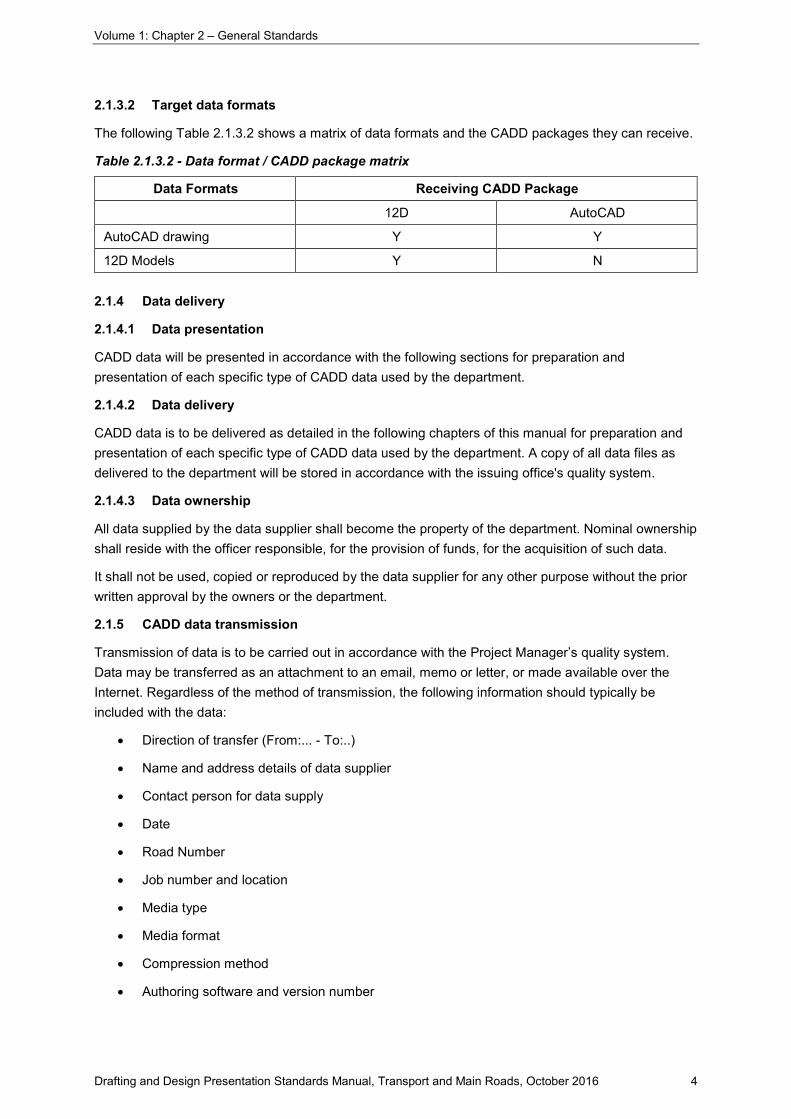
2.1.3.2 Target data formats
The following Table 2.1.3.2 shows a matrix of data formats and the CADD packages they can receive.
Table 2.1.3.2 - Data format / CADD package matrix
Data Formats Receiving CADD Package
12D AutoCAD
AutoCAD drawing Y Y
12D Models Y N
2.1.4 Data delivery
2.1.4.1 Data presentation
CADD data will be presented in accordance with the following sections for preparation and presentation of each specific type of CADD data used by the department.
2.1.4.2 Data delivery
CADD data is to be delivered as detailed in the following chapters of this manual for preparation and presentation of each specific type of CADD data used by the department. A copy of all data files as delivered to the department will be stored in accordance with the issuing office's quality system.
2.1.4.3 Data ownership
All data supplied by the data supplier shall become the property of the department. Nominal ownership shall reside with the officer responsible, for the provision of funds, for the acquisition of such data.
It shall not be used, copied or reproduced by the data supplier for any other purpose without the prior written approval by the owners or the department.
2.1.5 CADD data transmission
Transmission of data is to be carried out in accordance with the Project Manager’s quality system. Data may be transferred as an attachment to an email, memo or letter, or made available over the Internet. Regardless of the method of transmission, the following information should typically be included with the data:
• Direction of transfer (From:... - To:..)
• Name and address details of data supplier
• Contact person for data supply
• Date
• Road Number
• Job number and location
• Media type
• Media format
• Compression method
• Authoring software and version number
Volume 1: Chapter 2 – General Standards
Drafting and Design Presentation Standards Manual, Transport and Main Roads, October 2016 5
• Data format
• CADD filename(s) and description(s)
• Adequacy of data and data verification (proof plot etc.)
• Person responsible for data verification.
2.1.6 Naming convention for modelling systems
For uniformity throughout all departmental design offices within the state, a standard naming convention for models and strings has been developed for use within all design software modelling packages.
2.1.6.1 Model naming convention
To take full advantage of current and future automated procedures within our modelling packages (i.e. TMR Customisation), a standard model naming convention is required. Designers and constructors then will have immediate recognition of model contents no matter from which design office the project originated.
This naming convention follows closely the names associated with the types of models and the surfaces they contain. Appendix 2C contains a list of the model names to be adopted together with a brief description of their contents.
2.1.6.2 Survey feature codes
All survey feature coding and modelling must be in accordance with the department's current standards as set out in TMR Surveying Standards. No variations will be allowed to the codes, symbols, line styles or designated models for each code.
2.1.6.3 Design string naming convention
TMR has adopted a standard convention for the naming of design model strings. The use of a labelling convention during design will allow for a more efficient use of current and future automated features. These features, such as the transfer of data, are available within existing design software.
A further benefit of a standard String Naming Convention (SNC) is that a string label signifies the same feature throughout all design offices and to all constructors. This results in easier understanding of any project model regardless of the origin of the design.
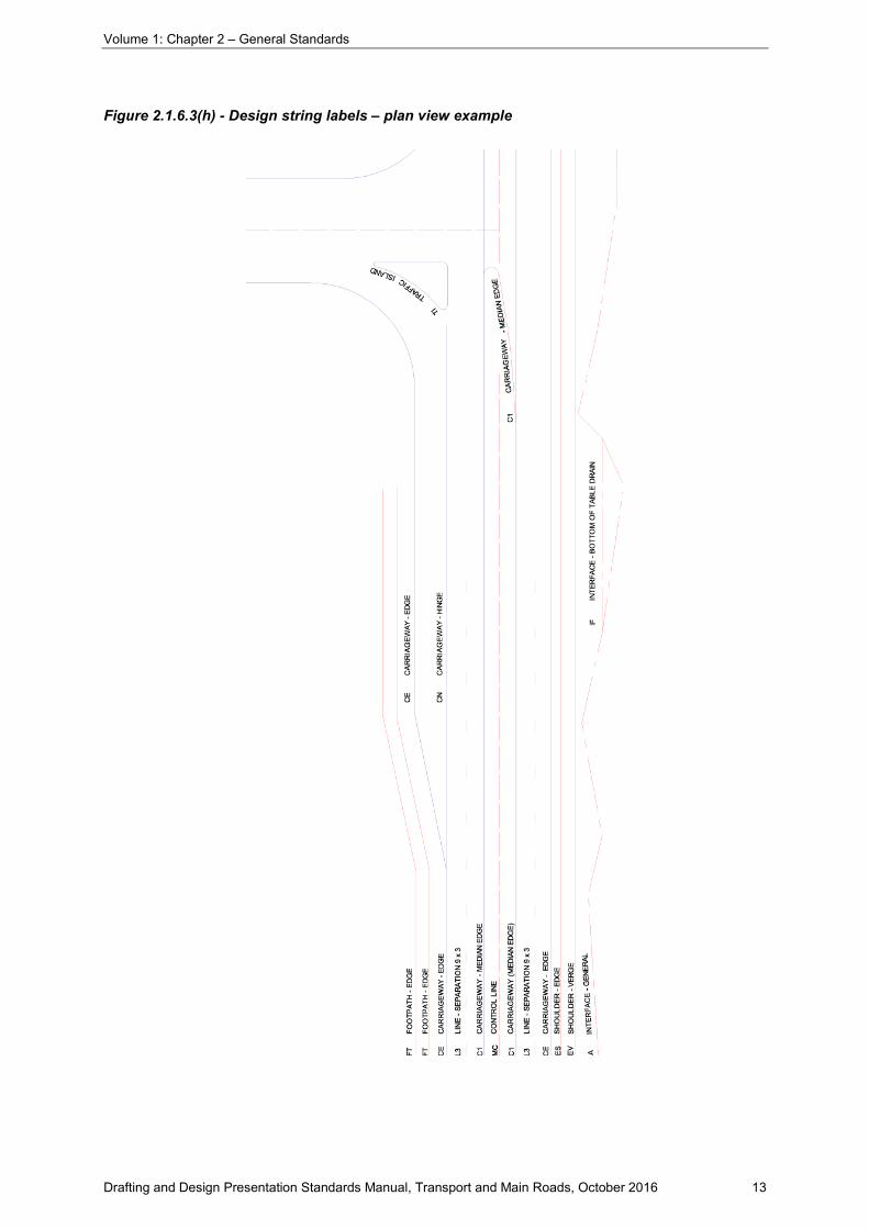
Appendix 2A, represents the department’s design string naming convention. In most cases only the first two characters of the string label are relevant for string recognition. The number of characters in the string label and its definition will be dependant on the modelling software used. Line style names have also been included. See also Section 2.3.
Examples showing design elements for roadways of the string naming convention are included as Figure 2.1.6.3(a) to Figure 2.1.6.3(i). Bridge feature string naming convention is included as Figure 2.1.6.3(j) to Figure 2.1.6.3(n).

Volume 1: Chapter 2 – General Standards
Drafting and Design Presentation Standards Manual, Transport and Main Roads, October 2016 6
Figure 2.1.6.3(a) - Typical cross section of two lane two way rural road

Volume 1: Chapter 2 – General Standards
Drafting and Design Presentation Standards Manual, Transport and Main Roads, October 2016 7
Figure 2.1.6.3(b) - Typical cross section of multilane rural road – independently aligned

Volume 1: Chapter 2 – General Standards
Drafting and Design Presentation Standards Manual, Transport and Main Roads, October 2016 8
Figure 2.1.6.3(c) - Typical cross section of undivided urban road

Volume 1: Chapter 2 – General Standards
Drafting and Design Presentation Standards Manual, Transport and Main Roads, October 2016 9
Figure 2.1.6.3(d) - Typical cross section of multilane urban road

Volume 1: Chapter 2 – General Standards
Drafting and Design Presentation Standards Manual, Transport and Main Roads, October 2016 10
Figure 2.1.6.3(e) - Typical cross section of urban arterial road – separated function type

Volume 1: Chapter 2 – General Standards
Drafting and Design Presentation Standards Manual, Transport and Main Roads, October 2016 11
Figure 2.1.6.3(f) - Typical cross section of urban arterial road – separated function type

Volume 1: Chapter 2 – General Standards
Drafting and Design Presentation Standards Manual, Transport and Main Roads, October 2016 12
Figure 2.1.6.3(g) - Typical cross section of multilane motorway (no transit lanes)
Volume 1: Chapter 2 – General Standards
Drafting and Design Presentation Standards Manual, Transport and Main Roads, October 2016 13
Figure 2.1.6.3(h) - Design string labels – plan view example

Volume 1: Chapter 2 – General Standards
Drafting and Design Presentation Standards Manual, Transport and Main Roads, October 2016 14
Figure 2.1.6.3(i) - Design string labels – drainage profile example

Volume 1: Chapter 2 – General Standards
Drafting and Design Presentation Standards Manual, Transport and Main Roads, October 2016 15
Figure 2.1.6.3(j) - Example of strings required for headstocks, pier columns and footing

Volume 1: Chapter 2 – General Standards
Drafting and Design Presentation Standards Manual, Transport and Main Roads, October 2016 16
Figure 2.1.6.3(k) - Example of strings required for headstocks, pier columns and piles

Volume 1: Chapter 2 – General Standards
Drafting and Design Presentation Standards Manual, Transport and Main Roads, October 2016 17
Figure 2.1.6.3(l) - Example of strings required for abutments

Volume 1: Chapter 2 – General Standards
Drafting and Design Presentation Standards Manual, Transport and Main Roads, October 2016 18
Figure 2.1.6.3(m) - Example of strings required for deck and kerbs

Volume 1: Chapter 2 – General Standards
Drafting and Design Presentation Standards Manual, Transport and Main Roads, October 2016 19
Figure 2.1.6.3(n) - Example of strings required for spillthrough

Volume 1: Chapter 2 – General Standards
Drafting and Design Presentation Standards Manual, Transport and Main Roads, October 2016 20
2.1.6.4 Project data file structure
To facilitate data retrieval and other processes within the department, it is necessary to have a common file structure for the long-term storage of relevant project data information.
All internal and external designers should adopt the following file structure. It divides the data directory path into Roads under which are placed relevant Projects. Under each project is placed the data for the software used under their various application names such as 12D, and AutoCAD / Map 3D.
Advantages to be achieved in using this method are:
• all relevant project files are kept together
• a common directory path is easily accessed by all users
• copying and archiving a project's data files is more easily achieved.
An example of this project data file structure is shown in Figure 2.1.6.4 and is recommended as a standard to be used in all design offices and by all consultants. It shows a typical road project folder for (17B)_Cunningham_Highway. Under this are held relevant Jobs such as (2)_Eight_Mile_Intersection. This folder then contains the project data for each of the software applications used for that project (e.g. 12D, AutoCAD/Map 3D). Also included is any project documentation as well as provision for Management Correspondence. On completion of the design the entire contents of the Project Folder is to be placed on CD(s) /DVD for distribution and archiving.
Figure 2.1.6.4 - Example of project data file structure
Volume 1: Chapter 2 – General Standards
Drafting and Design Presentation Standards Manual, Transport and Main Roads, October 2016 21
2.2 AutoCAD drawing environments and attributes
There are a number of components in a CAD drawing which are required to be understood properly when preparing a drawing for the department in order to efficiently manage the data within such AutoCAD drawing for the long-term, and simultaneously producing a drawing complying with the department’s Design and Drafting Presentation Standards.
Appendix 2E TMR AutoCAD Drawing Environments and Appendix 2F TMR Drawing Attributes provide guidelines in the preparation of CAD drawings to accomplish the above requirements.
2.3 Line types, symbols and text
2.3.1 Line types
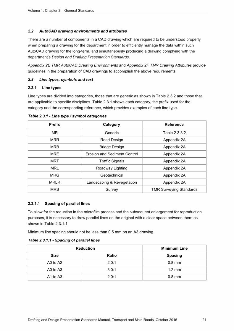
Line types are divided into categories, those that are generic as shown in Table 2.3.2 and those that are applicable to specific disciplines. Table 2.3.1 shows each category, the prefix used for the category and the corresponding reference, which provides examples of each line type.
Table 2.3.1 - Line type / symbol categories
Prefix Category Reference
MR Generic Table 2.3.3.2
MRR Road Design Appendix 2A
MRB Bridge Design Appendix 2A
MRE Erosion and Sediment Control Appendix 2A
MRT Traffic Signals Appendix 2A
MRL Roadway Lighting Appendix 2A
MRG Geotechnical Appendix 2A
MRLR Landscaping & Revegetation Appendix 2A
MRS Survey TMR Surveying Standards
2.3.1.1 Spacing of parallel lines
To allow for the reduction in the microfilm process and the subsequent enlargement for reproduction purposes, it is necessary to draw parallel lines on the original with a clear space between them as shown in Table 2.3.1.1
Minimum line spacing should not be less than 0.5 mm on an A3 drawing.
Table 2.3.1.1 - Spacing of parallel lines
Reduction Minimum Line
Size Ratio Spacing
A0 to A2 2.0:1 0.8 mm
A0 to A3 3.0:1 1.2 mm
A1 to A3 2.0:1 0.8 mm

Volume 1: Chapter 2 – General Standards
Drafting and Design Presentation Standards Manual, Transport and Main Roads, October 2016 22
2.3.2 Symbols
Symbols are also divided into categories applicable to specific disciplines. Refer to Appendix 2A for design symbols and string naming conventions.
The departments' customised features in AutoCAD contains blocks of all the required symbols and features used for scheme presentation purposes as follows:
• Kerb types as shown on Standard Drawing 1033 Kerb and channel – Kerbs, channels and ramped vehicular crossing of the Standard Drawings Manual
• Selected traffic signs and pavement markings as shown in the Manual of Uniform Traffic Control Devices (MUTCD)
• North Points
• Scale Bars
• Selected standard notes.
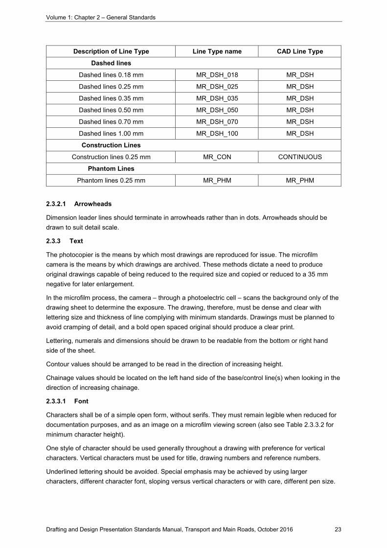
Table 2.3.2 - Standard line types (generic)
Description of Line Type Line Type name CAD Line Type
Continuous lines
Continuous lines 0.18 mm MR_CON_018 CONTINUOUS
Continuous lines 0.25 mm MR_CON_025 CONTINUOUS
Continuous lines 0.35 mm MR_CON_035 CONTINUOUS
Continuous lines 0.50 mm MR_CON_050 CONTINUOUS
Continuous lines 0.70 mm MR_CON_070 CONTINUOUS
Continuous lines 1.00 mm MR_CON_100 CONTINUOUS
Chain lines
Chain lines 0.18 mm MR_CHN_018 MR_CHN
Chain lines 0.25 mm MR_CHN_025 MR_CHN
Chain lines 0.35 mm MR_CHN_035 MR_CHN
Chain lines 0.50 mm MR_CHN_050 MR_CHN
Chain lines 0.70 mm MR_CHN_070 MR_CHN
Chain lines 1.00 mm MR_CHN_100 MR_CHN
Double dashed chain lines
Double dashed chain lines 0.18 mm MR_DCH_018 MR_DCH
Double dashed chain lines 0.25 mm MR_DCH_025 MR_DCH
Double dashed chain lines 0.35 mm MR_DCH_035 MR_DCH
Double dashed chain lines 0.50 mm MR_DCH_050 MR_DCH
Double dashed chain lines 0.70 mm MR_DCH_070 MR_DCH
Double dashed chain lines 1.00 mm MR_DCH_100 MR_DCH
Volume 1: Chapter 2 – General Standards
Drafting and Design Presentation Standards Manual, Transport and Main Roads, October 2016 23
Description of Line Type Line Type name CAD Line Type
Dashed lines
Dashed lines 0.18 mm MR_DSH_018 MR_DSH
Dashed lines 0.25 mm MR_DSH_025 MR_DSH
Dashed lines 0.35 mm MR_DSH_035 MR_DSH
Dashed lines 0.50 mm MR_DSH_050 MR_DSH
Dashed lines 0.70 mm MR_DSH_070 MR_DSH
Dashed lines 1.00 mm MR_DSH_100 MR_DSH
Construction Lines
Construction lines 0.25 mm MR_CON CONTINUOUS
Phantom Lines
Phantom lines 0.25 mm MR_PHM MR_PHM
2.3.2.1 Arrowheads
Dimension leader lines should terminate in arrowheads rather than in dots. Arrowheads should be drawn to suit detail scale.
2.3.3 Text
The photocopier is the means by which most drawings are reproduced for issue. The microfilm camera is the means by which drawings are archived. These methods dictate a need to produce original drawings capable of being reduced to the required size and copied or reduced to a 35 mm negative for later enlargement.
In the microfilm process, the camera – through a photoelectric cell – scans the background only of the drawing sheet to determine the exposure. The drawing, therefore, must be dense and clear with lettering size and thickness of line complying with minimum standards. Drawings must be planned to avoid cramping of detail, and a bold open spaced original should produce a clear print.
Lettering, numerals and dimensions should be drawn to be readable from the bottom or right hand side of the sheet.
Contour values should be arranged to be read in the direction of increasing height.
Chainage values should be located on the left hand side of the base/control line(s) when looking in the direction of increasing chainage.
2.3.3.1 Font
Characters shall be of a simple open form, without serifs. They must remain legible when reduced for documentation purposes, and as an image on a microfilm viewing screen (also see Table 2.3.3.2 for minimum character height).
One style of character should be used generally throughout a drawing with preference for vertical characters. Vertical characters must be used for title, drawing numbers and reference numbers.
Underlined lettering should be avoided. Special emphasis may be achieved by using larger characters, different character font, sloping versus vertical characters or with care, different pen size.

Volume 1: Chapter 2 – General Standards
Drafting and Design Presentation Standards Manual, Transport and Main Roads, October 2016 24
Vertical characters/numerals are to be used where they refer to either established or existing data and features. Referencing to design information and design details should be shown in italic. For example, height values established by survey as recorded in the survey books, such as for spot and BM's, would be shown vertical. Interpolated height values would be shown sloping. In addition, designed heights would be shown sloping.
Various approved fonts, for general use in the preparation of departmental drawings, have been selected because of their legibility and acceptability to the microfilming standards. These shapes and their proportions have been included as standards in the department's computer aided drafting (CAD) package. The standard font is called MR_ROMANS and is based on ROMANS with a width factor of 0.8.
2.3.3.2 Height of characters
The height, in millimetres, of characters on original (full scale) drawings should preferably be one of the following:
• 2.5*, 3.5, 5, 7, 10, 14, 20 (*note – not suitable for reduction).
These text heights are included as standard sizes in the department’s TMR AutoCAD Customisation system. Other heights may be used provided that the minimum height requirements of this clause are met.
The minimum height of characters is shown in Table 2.3.3.2 and is to be adopted on original drawings for the various reductions required for documentation purposes. TMR Customisation requires that text be shown in upper and lower case. Some notes and text have been forced to upper case in TMR’s Customisation for their importance. When reduced for scheme documentation the character height for capitals should desirably be not less than 1.5 mm. Table 2.3.3.2 shows the minimum heights of characters.
Table 2.3.3.2 - Minimum height of characters on drawings
Reduction Character Size Character Size
Original drawings Reduced Drawings
Size Ratio Caps Caps/ lower case Caps Caps/ lower
case
A0>A3 ≈3:1 4.5 5.0 1.5 ≈1.7
A1>A3 2:1 3.0# 3.5 1.5 1.75
# note - 3.0 mm is not a standard text height and may only be used where all characters are capitals and where its use can be justified due to limited space on a drawing.
2.3.3.3 Thickness of character pen strokes
The German standards DIN 15, 16, 17, Series 1 refer to the ratio of lettering thickness to height for microfilming purposes. Two ratios are referred to:
• 1:10 medium thick, and
• 1:14 thin.
Use of the 1:10 ratio is consistent with departmental practice, however 1:14 may be achieved using the next finer pen.

Volume 1: Chapter 2 – General Standards
Drafting and Design Presentation Standards Manual, Transport and Main Roads, October 2016 25
2.3.3.4 Spacing between lines of lettering
Line spacing is not to be less than 1.6 'h', where 'h' is the height of capitals. This is normally a predefined standard in CAD packages.
2.3.3.5 Fractions/decimals
All values that are not whole numbers shall be expressed in decimal form to two decimal places. Where the quantity is less than one, the decimal should be preceded by the number '0', e.g. 0.45. The number of decimal places is two. Chainages to be to three decimal places. Concrete to one decimal place. Reference MRS01 Introduction to Specifications.
2.3.3.6 Abbreviations, contractions and acronyms
This section details the abbreviations, contractions and acronyms, glossary of terms and units of measurements, which have been selected from those commonly used in civil engineering drawings and documents.
It is necessary that consistency of usage be maintained throughout the department, particularly in relation to the presentation in contract documents.
The object of using shortened forms is to save space and make reading easier by avoiding needless repetition. They should not be used for their own sake but only when appropriate. Their best use is with words and phrases which are important in context but become so familiar to the reader, from constant repetition, that all the reader needs is some simple code to identify them.
The word 'contraction' refers to a shortened form of a word that ends in the same letter as the word itself (e.g. Dept for Department). The word 'abbreviation' refers to a shortened form consisting of the initial letter alone or of the initial letter followed by other letters of the word except the final one (e.g. Mon. for Monday). Contractions normally have no full stop, abbreviations normally do. Avoid using apostrophes in abbreviations and contractions.
An acronym is a word developed usually from the initial letters of other words. These letters are always in capitals, e.g. Reinforced Concrete Slab Deck Culvert (RCSDC). Common departmental usage is shown in Table 2.3.3.8(a).
The correct names of Local Authorities and Roads must be used. Some minor abbreviations and contractions of road names will be permitted as indicated below but in general, if space is available, the full names should be given:
Highway Hwy
Road Rd
Shire Sh.
Developmental Dev.
Town T.
City C.
Note that although highways and developmental roads have numbered and lettered sections to assist in identification, they are known by name only, never by number.
Contractions in place names are discouraged but if it should be decided to shorten place names, care must be taken that the contraction is well known with no misinterpretation.

Volume 1: Chapter 2 – General Standards
Drafting and Design Presentation Standards Manual, Transport and Main Roads, October 2016 26
For example, the following may be acceptable:
Townsville Tville
Rockhampton Rton
Bundaberg Bberg
Charters Towers Ch. Towers
Reference 2 tabulates further abbreviations outside normal departmental usage.
2.3.3.7 Glossary of terms
Words and terms that have specific meaning in road design and construction are generally to be adopted from Australian Standard AS 1348.1. Where conflict arises between departmental terminology and the Australian Standard, the departmental standard shall prevail.
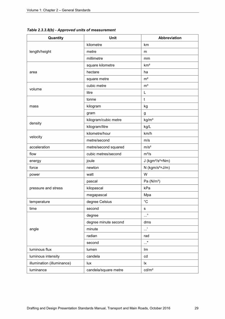
2.3.3.8 Units of measurements
There are many units of measurements commonly used in society, e.g. centimetre, which are not to be used in departmental documents. Table 2.3.3.8(b) lists the approved units of measurements together with their abbreviations that are to be used in the department's documentation.
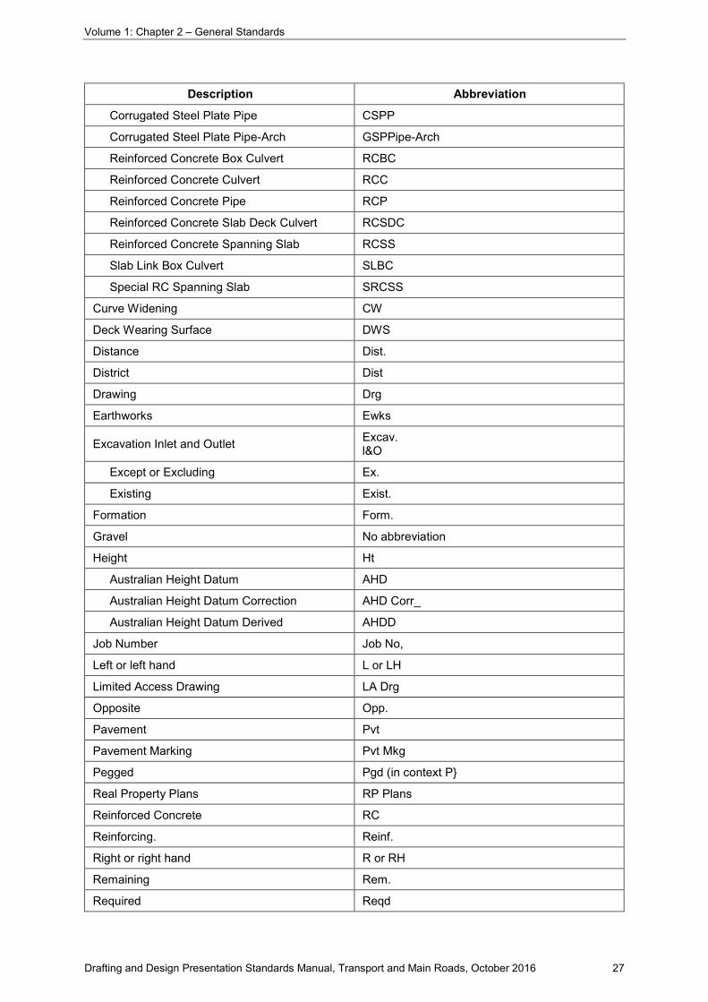
Table 2.3.3.8(a) - Approved shortened forms
Description Abbreviation
About Abt
Approximate Approx.
Authorisation Auth.
Auxiliary Aux
Bitumen Bit_
Boundary Bdy
Centre Line CL (prefer C)
Chainage Ch
Communication Cables:
Low Band L (line type use)
High Band H (line type use)
Coaxial Cx
FibreOptics FO
Coordinate Geometry System COGO
Roadway Earthworks Design System REDS
Control Ctl
Crossfall Cfall
Culvert Clvt
Corrugated Steel Helical Pipe CSHP
Corrugated Steel Nestable Pipe GSNP
Corrugated Steel Plate Arch CSPA
Volume 1: Chapter 2 – General Standards
Drafting and Design Presentation Standards Manual, Transport and Main Roads, October 2016 27
Description Abbreviation
Corrugated Steel Plate Pipe CSPP
Corrugated Steel Plate Pipe-Arch GSPPipe-Arch
Reinforced Concrete Box Culvert RCBC
Reinforced Concrete Culvert RCC
Reinforced Concrete Pipe RCP
Reinforced Concrete Slab Deck Culvert RCSDC
Reinforced Concrete Spanning Slab RCSS
Slab Link Box Culvert SLBC
Special RC Spanning Slab SRCSS
Curve Widening CW
Deck Wearing Surface DWS
Distance Dist.
District Dist
Drawing Drg
Earthworks Ewks
Excavation Inlet and Outlet Excav. l&O
Except or Excluding Ex.
Existing Exist.
Formation Form.
Gravel No abbreviation
Height Ht
Australian Height Datum AHD
Australian Height Datum Correction AHD Corr_
Australian Height Datum Derived AHDD
Job Number Job No,
Left or left hand L or LH
Limited Access Drawing LA Drg
Opposite Opp.
Pavement Pvt
Pavement Marking Pvt Mkg
Pegged Pgd (in context P}
Real Property Plans RP Plans
Reinforced Concrete RC
Reinforcing. Reinf.
Right or right hand R or RH
Remaining Rem.
Required Reqd

Volume 1: Chapter 2 – General Standards
Drafting and Design Presentation Standards Manual, Transport and Main Roads, October 2016 28
Description Abbreviation
Restricted Visibility Widening RVW
Resumption Drawing RDrg
Rock No abbreviation
Crushed Cr.
Uncrushed Uncr.
Handpacked Hndpkd
Round Fence Post RFP
Square Fence Post SEP
Shift Sh (in contex 5)
Special Spcl
Superelevation Super.
Surfacing or Surface Surf.
Survey Svy
Benchmark BM
Cadastral Survey Mark CSM
Field Book FB
Geocentric Datum of Australia GDA
Level Book LB
Universal Survey Book USB
Instrument (traverse Station) Station IS
Land Survey Pin LSPin
Land Survey Plans LS Plans
Land Survey Post LS Post
Map Grid of Australia MGA
Offset Peg OP
Offset Mark OM
Permanent Reference Point PRP
Permanent Survey Mark PSM
Project Control Station PCS
Survey Mark SM
Vertical Curve VC
Working Drawing W Drg
Volume 1: Chapter 2 – General Standards
Drafting and Design Presentation Standards Manual, Transport and Main Roads, October 2016 29
Table 2.3.3.8(b) - Approved units of measurement
Quantity Unit Abbreviation
length/height
kilometre km
metre m
millimetre mm
area
square kilometre km²
hectare ha
square metre m²
volume cubic metre m³
litre L
mass
tonne t
kilogram kg
gram g
density kilogram/cubic metre kg/m³
kilogram/litre kg/L
velocity kilometre/hour km/h
metre/second m/s
acceleration metre/second squared m/s²
flow cubic metres/second m³/s
energy joule J (kgm²/s²=Nm)
force newton N (kgm/s²=J/m)
power watt W
pressure and stress
pascal Pa (N/m²)
kilopascal kPa
megapascal Mpa
temperature degree Celsius °C
time second s
angle
degree ...°
degree minute second dms
minute ...'
radian rad
second ..."
luminous flux lumen Im
luminous intensity candela cd
illumination (illuminance) lux lx
luminance candela/square metre cd/m²

Volume 1: Chapter 2 – General Standards
Drafting and Design Presentation Standards Manual, Transport and Main Roads, October 2016 30
Quantity Unit Abbreviation
PREFIXES
10-6 - micro µ
10-3 - milli m
103 - kilo k
106 - mega M
2.3.3.9 Chainages
Standard alignment descriptions and notation are shown in Figure 2.3.3.10(a) and Table 2.3.3.10.
Chainages are shown on the drawing sheets generally left to right in the direction of increasing chainage (road gazettal).
Chainages are to be given at the beginning and end of each plan and are normally shown at the top of the control line. These chainages are normally at intervals of 100 m and at a regular offset from the control line.
Control line chainages are generally to be clear of road boundaries and details and positioned in such a way as to identify the relevant chainage mark. All chainages and references to the alignment are to be in italic. It may be necessary in extreme cases of curved alignment to draw lead lines (thin, short, and broken) to the points to which they refer.
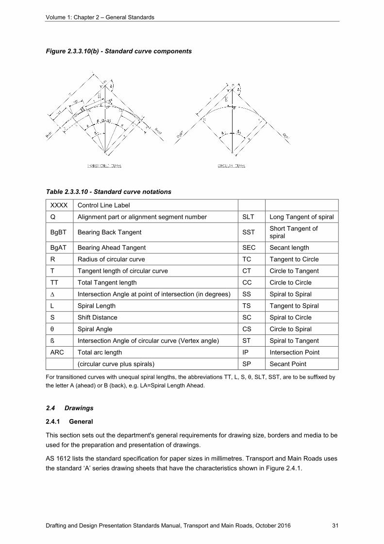
2.3.3.10 Curve components
Standard curve component descriptions and notation are shown in Figure 2.3.3.10(b) and Table 2.3.3.10.
In urban schemes, where complex geometry is used, it may be necessary to show the full geometric details for use by field staff during construction. Normally all that is required for a control line are the tangent points that occur between straights for transitioned curves and circular curves.
These should be shown on the drawings in the form of their relevant abbreviation and corresponding chainage.
Figure 2.3.3.10(a) - Standard alignment
Volume 1: Chapter 2 – General Standards
Drafting and Design Presentation Standards Manual, Transport and Main Roads, October 2016 31
Figure 2.3.3.10(b) - Standard curve components
Table 2.3.3.10 - Standard curve notations
XXXX Control Line Label
Q Alignment part or alignment segment number SLT Long Tangent of spiral
BgBT Bearing Back Tangent SST Short Tangent of spiral
BgAT Bearing Ahead Tangent SEC Secant length
R Radius of circular curve TC Tangent to Circle
T Tangent length of circular curve CT Circle to Tangent
TT Total Tangent length CC Circle to Circle
∆ Intersection Angle at point of intersection (in degrees) SS Spiral to Spiral
L Spiral Length TS Tangent to Spiral
S Shift Distance SC Spiral to Circle
θ Spiral Angle CS Circle to Spiral
ß Intersection Angle of circular curve (Vertex angle) ST Spiral to Tangent
ARC Total arc length IP Intersection Point
(circular curve plus spirals) SP Secant Point
For transitioned curves with unequal spiral lengths, the abbreviations TT, L, S, θ, SLT, SST, are to be suffixed by the letter A (ahead) or B (back), e.g. LA=Spiral Length Ahead.
2.4 Drawings
2.4.1 General
This section sets out the department's general requirements for drawing size, borders and media to be used for the preparation and presentation of drawings.
AS 1612 lists the standard specification for paper sizes in millimetres. Transport and Main Roads uses the standard ‘A’ series drawing sheets that have the characteristics shown in Figure 2.4.1.

Volume 1: Chapter 2 – General Standards
Drafting and Design Presentation Standards Manual, Transport and Main Roads, October 2016 32
Figure 2.4.1 Characteristics of ‘A’ series paper size
A standard drawing sheet depicts a standard title block and border with the overall sheet sizes outlined in Table 2.4.1.
Table 2.4.1 - Standard drawing sheets
Sheet Designation Trimmed Width (W) mm Trimmed Length (L) mm
A0 841 1189
A1 594 841
A2 420 594
A3 297 420
A4 210 297
A drawing refers to a standard drawing sheet with project design and construction information included together with a completed title block. When completed this forms part of a scheme prototype document.
2.4.2 Drawing size
The cost and time in drawing preparation and the serviceability of the finished product in use must be taken into account when making initial decisions as to the basic drawing sheet material and size. Throughout a particular scheme, it is necessary to adopt a standard drawing size. Therefore, when drawing work is undertaken by more than one office, early liaison is necessary.
A4 or smaller is not to be used for final drawing presentation.
2.4.3 Drawing sheets
2.4.3.1 Electronic drawing sheets
The department has developed standard electronic drawing sheets in the sizes and for the uses specified in Table 2.4.3.1 and as shown in Appendix 2D: TMR Drawing Sheets.
These drawing sheets are included in the electronic drawing and are output when the drawing is plotted. These frames are available as part of the department's standardised drafting system and are made available to outside parties engaged to prepare drawings for the department as requested.
Title block formats have been standardised in order to facilitate the inclusion of the necessary information in a uniform manner.
The information presented in Appendix 2D provides guidelines for predefined information associated with drawings created using the TMR Customisation.

Volume 1: Chapter 2 – General Standards
Drafting and Design Presentation Standards Manual, Transport and Main Roads, October 2016 33
Table 2.4.3.1 - Standard electronic drawing sheets
Drawing Type Discipline Drawing Sheet Name Usage
GENERAL E.g. Locality Plan and Drawing List
MRR_Detail
E.g. MRR_Detail with “scheme scope approval statement” and “drawing list table”
Miscellaneous
E.g: First sheet(s) in series
ROAD DESIGN AND CIVIL WORKS MRR_Detail Detail plan drawings
BRIDGE DESIGN MRB_Detail Bridge detail drawings
ROADWAY LIGHTING MRR_Detail Detail Plan drawings
TRAFFIC SIGNALS MRT_Detail Traffic signals cabling table
Detail Plan drawings
GEOTECHNICAL MRG_Detail Geotechnical drawings
RIGHT OF WAY
MRR_Resumption Resumption drawings
MRR_Native Title Native Title drawings
MRR_Limited Access Limited Access drawings
ROAD DECLARATION These plans are prepared in MapInfo Road Declaration drawings
Notes:
1- All the above standard drawing sheets are size A1. 2- Refer to Appendix 2D for detailed drawing sheets.
2.4.3.2 North point
Where possible, it is preferred that all plans in a drawing set share the same orientation on the drawing sheet.
North points are to occupy (where practicable) the same position within the standard border for each sheet throughout the drawing set.
2.4.3.3 Sheet overlap
The plan information depicted on sheets is to overlap marginally with immediately preceding and succeeding drawings within the documentation set.
This will assist in the overall legibility of site drawings by demonstrating each drawings relationship to adjoining ones.
A minimum of 15 mm page space overlap (at A1 size) is recommended, depending on the road alignment.
2.4.3.4 Adjoins lines and numbers
Each drawing must bear a reference to preceding and succeeding drawings within the drawing set.
The drawing number of adjoining preceding and succeeding drawings is to be printed parallel to and against the right and/or left hand borders of the drawing.
The line at which adjoining drawings abut is also to be clearly marked along the width of the drawing.

Volume 1: Chapter 2 – General Standards
Drafting and Design Presentation Standards Manual, Transport and Main Roads, October 2016 34
2.4.3.5 Issue identifier
The Department has develop plot stamps. If used each page of the drawing set is to be clearly marked near the top left hand corner with the relevant drawing sets issue identifier during drawing development stages prior to completion and release approval:
• Preliminary
• Preliminary Advice Only
• Issued for Pricing Only
• Issued for Constructability
• Issued for Review
• Issued for Check
• Issued for Tender
• Not for Construction
The names are for the different stages of each drawing issued, and must have the date and time clearly within this plot stamp detailing when the drawing is plotted.
Preliminary
These are preliminary drawings comprising the workings/ building up or development of the design i.e. design work in progress.
Preliminary Advice Only
Typically Preliminary Advice Only drawings would still be under development. These drawings may be transmitted to other parties and signifies the drawings are not final and may change.
Issued for Pricing Only
Issued for Pricing Only drawings are provided for the taking off of quantities and development of unit rates.
Issued for Constructability
Issued for Constructability drawings are those prepared for review/check by all stakeholders that is, public utility plant services managers, electrical, structural, landscaping specialists, environmental, maintenance and construction personnel and other officers necessary to provide input into design.
Issued for Review
These drawings are typically issued during the design review process to ensure broad compliance with engineering standards and technical governance across TMR, to meet the intent of the documented policies, standards and systems.
Issued for Check
These drawings are issued for the checking prior to final completion to ensure the design meets the requirements of the brief, expectations of the District and a rigorous scheme prototype check.
Issued for Tender
For Transport Infrastructure Contracts - Construct Only (TIC-CO), these are final detailed design drawings (they are ‘Issued For Construction’ drawings) issued for tender purposes so that

Volume 1: Chapter 2 – General Standards
Drafting and Design Presentation Standards Manual, Transport and Main Roads, October 2016 35
tenderers/proponents submit a price for constructing the project. Drawings show sufficient detail so that there is not significant change and subsequently no significant change of the construction cost.
The above also applies for Transport Infrastructure Contracts - Sole Invitation (TIC-SI).
For Transport Infrastructure Contracts - Design and Construct (TIC-DC), these are drawings of the preliminary design, also known as reference design, issued for tender purposes. Drawings show sufficient detail but tenderers/proponents are expected to further develop the design and fine tune it to provide a tender proposal including cost which demonstrates fit for purpose, value for money and best design practices. Further changes to the design are expected throughout the design and construct process.
Not for Construction
These drawings are not to be used for construction purposes. These drawings may be distributed for information only or for any other reason not listed above.
2.4.3.6 Consultants logo
Where drawing/s are prepared by a consultant their logo is to appear in the top right corner of the drawing sheet.
2.4.3.7 Drawing Revisions
'Revision clouds' with corresponding ‘alphabetical revision identifier’ are to be used when there have been amendments on previously approved drawings. This revisions cloud will outline the modification being made to that particular drawing. The revisions area in the bottom left of the title block is to be filled in outlining the modification being made to the drawing. Also refer to Chapter 1, Section 1.7.1.2.
2.4.4 Drawing media
2.4.4.1 Use of media
Tracing, bond and high gloss papers and double matte polyester films can be supplied for general drafting purposes in sheets or rolls to suit most ink jet printers or plotters.
It is essential that the correct plotting media, suitable for the required presentation standard, be used when plotting on electronic printers or plotters.
2.4.4.2 Preliminary drawings
Drawings provided for preliminary purposes are to be plotted on plain paper.
2.4.4.3 Final drawings
Final drawings for approval and release are now produced as A3 size. A media called A3 Permanent Paper, ranging from 100mic to 135mic, has been found suitable for final drawing presentation. It will not rip or smudge and produces drawings suitable for storage and microfilming.
A1 size film is also a suitable medium for approval and release as it is a stable medium to store and archive, also it reproduces well when it comes to microfilming as the mat finish on the film does not cause flaring.
The colours of all standard line types and symbols have been chosen so that they are reproducible when photocopied and retain their legibility when microfilmed.
Drawings are to be printed on the media and at the size set out in the brief.

Volume 1: Chapter 2 – General Standards
Drafting and Design Presentation Standards Manual, Transport and Main Roads, October 2016 36
2.4.5 Title block data
2.4.5.1 Job numbers
The Job Number is the unique project identifier used through the concept, development and implementation phases. On major projects a ‘900’ series job number may be issued for the project to the end of business case. A different job number will then be issued for the development and implementation phase.
The purpose of this number is to track all project specified correspondence, to capture total project costs and for reporting purposes. This number is identified in the Queensland Transport and Roads Investment Program (QTRIP), which list the project, cost and construction timing. The Job Number will be shown on all drawings.
The format of the job number is LG/RD/JOB where:
• LG is the number allocated to the regional council shire council or city council.
• RD is the number allocated to the road or highway. An alpha character is usually suffixed to this number to indicate sections of a highway.
• JOB is the unique number issued to each project by the district.
The issue of the job number is the responsibility of the regional/district office.
Where a project is located within more than one local government area or on more than one state controlled road, multiple job numbers may be required. The job number relating to the coverage of the drawing shall be shown as the primary job number.
2.4.5.2 Contract numbers
A Contract Number is issued for the purpose of the administration of a construction contract. This number is in addition to the Job Number/s and will be shown on all the drawings, documents and correspondence with the construction contractor.
The common format of the Contract Number is ABCD-123 where:
• ABC is three characters representing the district name and D is for “district”.
• 123 is the unique number issued to each project by the district. This unique number is issued by the finance and procurement branch and this number can generally be made up of between 1 to 5 digits depending on each district (e.g. METD-3584, DDWD-8, SCHD-485, WBYD-35, etc.).
The issue of the contract numbers is the district responsibility. Only one contract number will be issued for each contract irrespective of how many job numbers.
2.4.5.3 Associated job numbers
On each drawing, other job numbers in the scheme are to be shown.
Where a project is located within more than one local government area or on more than one state controlled road, multiple job numbers may be required. The job number relating to the coverage of the drawing shall be shown as the primary job number.

Volume 1: Chapter 2 – General Standards
Drafting and Design Presentation Standards Manual, Transport and Main Roads, October 2016 37
2.4.5.4 Auxiliary drawing numbers
A listing of all drawings in the scheme is to be shown on all drawings. The Drawing Index sheet will also detail all drawings. This list will be identical on all drawings.
2.4.5.5 Through distance
The through distance (measured in kilometres to two decimals) from the start of gazettal shall be shown on all drawings. The origin point for the through distance may be a town or intersection but should be consistent with the department’s ARMIS system. The through distance will be measured to the start and end of the job.
2.4.5.6 Scales
The scale/s of the drawing shall be shown by the placing of a drawn scale bar annotated by numbers indicating the metric distance with the added wording “Metres”. The original A1 scale is not necessary.
2.5 References
• Australian Standard 1348.1, Road and Traffic Engineering – Glossary of Terms, Part 1 – Road Design and Construction. Standards Association of Australia, Sydney
• Engineering Handbook – Basic Principles and Techniques – ASCZ1, Part 1. Institute of Engineers, Australia
• Style Manual for Authors, Editors and Printers. Australian Government Publishing Service
• Standard Drawings Roads Manual. Department of Transport and Main Roads
• Manual of Uniform Traffic Control Devices (MUTCD Queensland)
• Australian Standard 1612, Paper sizes. Standards Association of Australia, Sydney
• TMR Surveying Standards. Department of Transport and Main Roads
