chapter # 2 cylindrical synchronous … · equivalent circuits of a cylindrical rotor synchronous...
TRANSCRIPT

Salman Bin Abdul Aziz University
College of Engineering
Electrical Engineering Department
EE 3360 Electrical Machines (II)
1 Dr. AHMED MUSTAFA HUSSEIN
CHAPTER # 2 CYLINDRICAL SYNCHRONOUS GENERATOR AND MOTOR
1. Introduction
Synchronous machines are named by this name as their speed is directly related to the
line frequency. Synchronous machines may be operated either as motor or generator.
Synchronous generators are called alternators. Synchronous motors are used mainly for
power factor correction when operate at no load. Synchronous machines are usually
constructed with stationary stator (armature) windings that carrying the current and
rotating rotor (field) winding that create the magnetic flux. This flux is produced by DC
current from a separate source (e.g. DC shunt generator).
2. Types of Synchronous Generators
The type of synchronous generators depends on the prime mover type as:
a) Steam turbines: synchronous generators that driven by steam turbine are high speed
machines and known as turbo alternators. The maximum rotor speed is 3600 rpm
corresponding 60 Hz and two poles.
b) Hydraulic turbines: synchronous generators that driven by water turbine are with
speed varies from 50 to 500 rpm. The type of turbine to be used depends on the water

Salman Bin Abdul Aziz University
College of Engineering
Electrical Engineering Department
EE 3360 Electrical Machines (II)
2 Dr. AHMED MUSTAFA HUSSEIN
head. For water head of 400m, Pelton wheel turbines are used. But for water head up to
350 m, Francis Turbines are used. For water head up to 50 m, Kaplan Turbines are
used.
c) Diesel Engines: they are used as prime movers for synchronous generator of small
ratings.
For the type a) and c) the rotor shape is cylindrical as shown in Fig. 1, and this type is
called cylindrical rotor synchronous machines. But for type b), the rotor has salient poles
on the rotor periphery as shown in Fig. 2.
Fig.1, Cylindrical-type synchronous machine
Fig.2, Salient-pole synchronous machine

Salman Bin Abdul Aziz University
College of Engineering
Electrical Engineering Department
EE 3360 Electrical Machines (II)
3 Dr. AHMED MUSTAFA HUSSEIN
3. Relation Between Field Flux and Armature Flux
There are two types of fluxes are obtained in the air gap between the armature and rotor;
- Field flux (Ff) that produced by the DC exciter and by using the appropriate prime
mover, it can rotate at synchronous speed (Ns).
- Armature flux or armature reaction (Fa) which is produced from 3-phase armature
winding and rotate with the synchronous speed.
Therefore, both of Ff and Fa are stationary w.r.t. each other
4. Equivalent Electrical Circuit Model per Phase
Neglecting saturation, the circuit diagrams, shown in Fig. 3 and 4, illustrate the per phase
equivalent circuits of a cylindrical rotor synchronous machine in the motor and generator
mode respectively.
Fig. 3, equivalent circuit (a) synchronous Generator (b) synchronous Motor

Salman Bin Abdul Aziz University
College of Engineering
Electrical Engineering Department
EE 3360 Electrical Machines (II)
4 Dr. AHMED MUSTAFA HUSSEIN
Fig. 4, equivalent circuit including leakage reactance and air-gap voltage
Ra armature resistance
XL Leakage reactance (corresponding to Leakage flux) saturation doesn't affect its value
Xa armature reactance (corresponding to Linkage flux) saturation affects its value
Ef the field voltage (Exciter DC voltage induced at the armature side)
Er the air-gap voltage which is the resultant between Ef and Ea
The leakage reactance XL and the armature reactance Xa may be combined to give
synchronous reactance XS.
XS =XL + Xa
Also, Ra + JXS is called synchronous impedance ZS
5. Phasor Diagram of Unsaturated Cylindrical Alternators
5.1 Lagging power factor
Assume that the synchronous generator is loaded with a lagging power factor load.
From the phasor diagram shown in Fig. 5, it is clear that the terminal voltage is decreased
from its no-load value Ef to its loaded value Va (for a lagging power factor). This is
because of: Drop due to armature resistance, IRa & drop due to leakage reactance, IXL
and drop due to armature reaction IXa.

Salman Bin Abdul Aziz University
College of Engineering
Electrical Engineering Department
EE 3360 Electrical Machines (II)
5 Dr. AHMED MUSTAFA HUSSEIN
Fig. 5, Phasor diagram for synchronous generator (p.f. Lag)
The angle (δ) between the no-load voltage (Ef) and the terminal voltage (Va) is called the
load angle or (power angle) and it is positive value in case of alternators.
The DC voltage (Excitation voltage) produces a flux (Φf) or (field mmf Ff). If the
armature circuit is closed by an electric load, the armature reaction (Φa) or (armature
mmf Fa) is produced. These two fluxes may support each other or oppose each other
depend on the load power factor to produce the air-gap or resultant flux (Φr) or (resultant
mmf Fr).
From the phasor diagram shown in Fig. 5,
Since Fr < Ff this means that Fa oppose Ff
Since Va < Ef this is called over-excited alternator
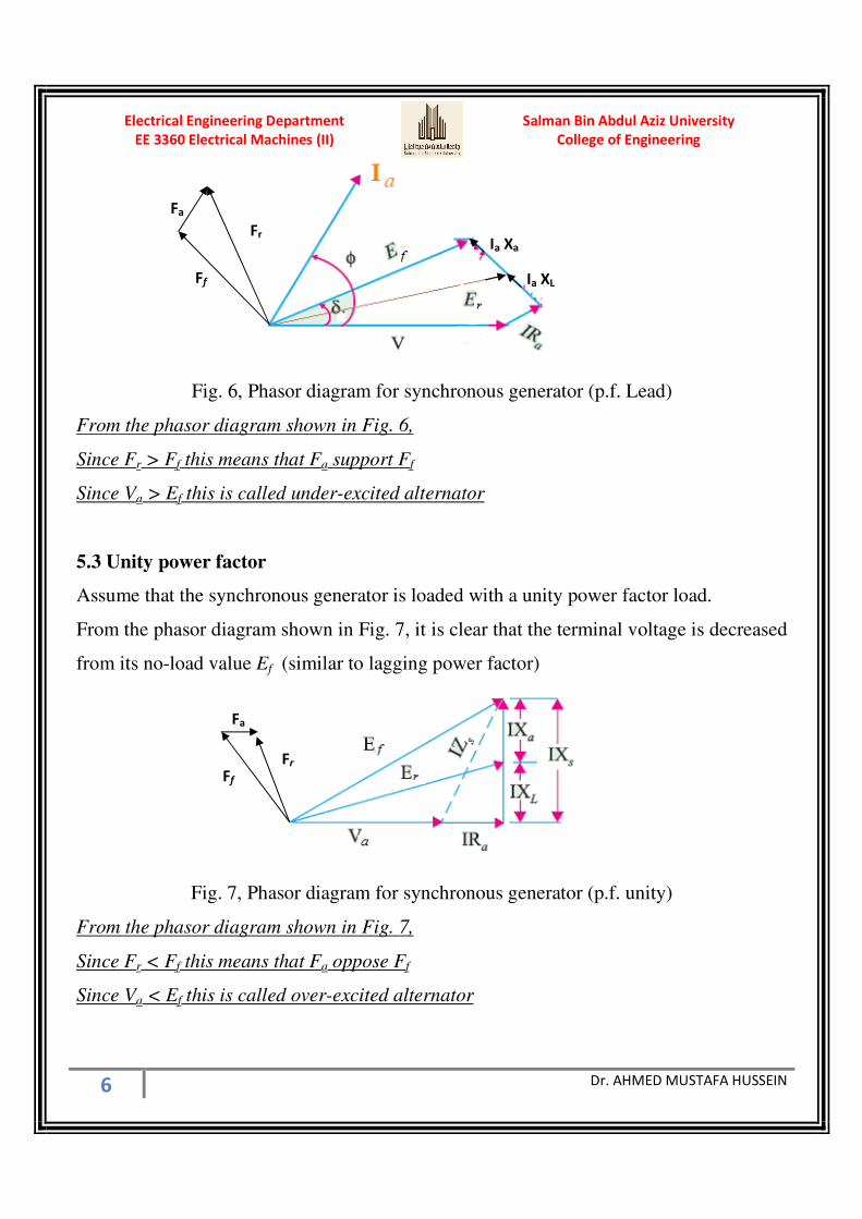
5.2 Leading power factor
Assume that the synchronous generator is loaded with a leading power factor load.
From the phasor diagram shown in Fig. 6, it is clear that the terminal voltage is increased
from its no-load value Ef
Fa
Ff Fr
Salman Bin Abdul Aziz University
College of Engineering
Electrical Engineering Department
EE 3360 Electrical Machines (II)
6 Dr. AHMED MUSTAFA HUSSEIN
Fig. 6, Phasor diagram for synchronous generator (p.f. Lead)
From the phasor diagram shown in Fig. 6,
Since Fr > Ff this means that Fa support Ff
Since Va > Ef this is called under-excited alternator
5.3 Unity power factor
Assume that the synchronous generator is loaded with a unity power factor load.
From the phasor diagram shown in Fig. 7, it is clear that the terminal voltage is decreased
from its no-load value Ef (similar to lagging power factor)
Fig. 7, Phasor diagram for synchronous generator (p.f. unity)
From the phasor diagram shown in Fig. 7,
Since Fr < Ff this means that Fa oppose Ff
Since Va < Ef this is called over-excited alternator
Ia XL
Ia Xa
Fr
Ff
Fa
Fa
Ff
Fr
Salman Bin Abdul Aziz University
College of Engineering
Electrical Engineering Department
EE 3360 Electrical Machines (II)
7 Dr. AHMED MUSTAFA HUSSEIN
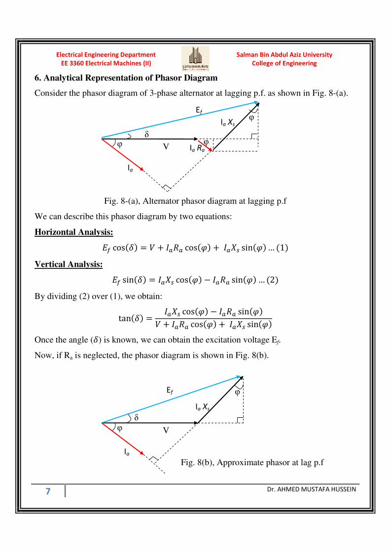
6. Analytical Representation of Phasor Diagram
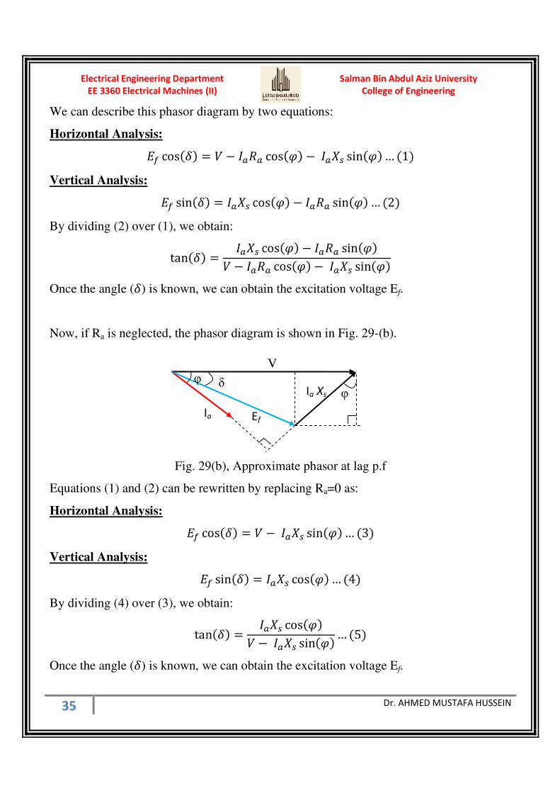
Consider the phasor diagram of 3-phase alternator at lagging p.f. as shown in Fig. 8-(a).
Fig. 8-(a), Alternator phasor diagram at lagging p.f
We can describe this phasor diagram by two equations:
Horizontal Analysis:
cos cos sin… 1 Vertical Analysis:
sin cos sin… 2 By dividing (2) over (1), we obtain:
tan cos sin cos sin
Once the angle () is known, we can obtain the excitation voltage Ef.
Now, if Ra is neglected, the phasor diagram is shown in Fig. 8(b).
Ef
Ia Xs
φ
φ
V
δ
Ia
Fig. 8(b), Approximate phasor at lag p.f
Ef
Ia Xs
φ
φ
V
δ
Ia
Ia Ra φ
Salman Bin Abdul Aziz University
College of Engineering
Electrical Engineering Department
EE 3360 Electrical Machines (II)
8 Dr. AHMED MUSTAFA HUSSEIN
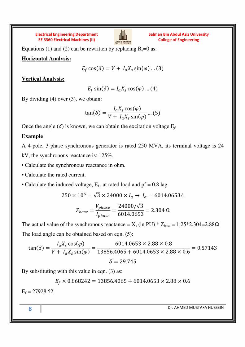
Equations (1) and (2) can be rewritten by replacing Ra=0 as:
Horizontal Analysis:
cos = + sin … 3
Vertical Analysis:
sin = cos … 4
By dividing (4) over (3), we obtain:
tan = cos + sin … 5
Once the angle () is known, we can obtain the excitation voltage Ef.
Example
A 4-pole, 3-phase synchronous generator is rated 250 MVA, its terminal voltage is 24
kV, the synchronous reactance is: 125%.
• Calculate the synchronous reactance in ohm.
• Calculate the rated current.
• Calculate the induced voltage, Ef , at rated load and pf = 0.8 lag.
250 × 10" = √3 × 24000 × → = 6014.0653'
()* = +,*+,* = 24000/√36014.0653 = 2.304 Ω
The actual value of the synchronous reactance = Xs (in PU) * Zbase = 1.25*2.304=2.88Ω
The load angle can be obtained based on eqn. (5):
tan = cos + sin = 6014.0653 × 2.88 × 0.813856.4065 + 6014.0653 × 2.88 × 0.6 = 0.57143
= 29.745
By substituting with this value in eqn. (3) as:
× 0.868242 = 13856.4065 + 6014.0653 × 2.88 × 0.6
Ef = 27928.52

Salman Bin Abdul Aziz University
College of Engineering
Electrical Engineering Department
EE 3360 Electrical Machines (II)
9 Dr. AHMED MUSTAFA HUSSEIN
By the same way, we can describe the phasor diagram in case of leading power factor
givenin Fig. 9-(a) by two equations:
Fig. 9-(a), Alternator phasor diagram at leading p.f
Horizontal Analysis:
cos cos sin… 6 Vertical Analysis:
sin cos sin… 7
By dividing (7) over (6), we obtain:
tan cos sin cos sin
Once the angle () is known, we can obtain the excitation voltage Ef.
Now, if Ra is neglected, the phasor diagram is shown in Fig. 9(b).
Ef
Ia Xs
φ
φ
V
δ
Ia
Fig. 9-b, Approximate phasor at leading p.f
V
Ef Ia Xs
φ
φ
δ
Ia
φ Ia Ra

Salman Bin Abdul Aziz University
College of Engineering
Electrical Engineering Department
EE 3360 Electrical Machines (II)
10 Dr. AHMED MUSTAFA HUSSEIN
Equations (6) and (7) can be rewritten by replacing Ra=0 as:
Horizontal Analysis:
cos = − sin … 8
Vertical Analysis:
sin = cos … 9
By dividing (9) over (8), we obtain:
tan = cos − sin
Once the angle () is known, we can obtain the excitation voltage Ef.
From the explained phasor diagrams given in Figs 5 to 9, we notice that V is always
behind Ef, this means the power angle (δ) is always positive, and this is the remarkable
notice on the phasor diagram of synchronous generators.
7. Experimental Determination of Circuit Parameters
In the per phase equivalent circuit model illustrated in section 1, there are three
parameters need to be determined: armature winding resistance Ra, synchronous
reactance Xs, and induced emf in the phase winding Va. The phase winding resistance Ra
can be determined by measuring DC resistance of the winding using volt-ampere method
(DC test), while the synchronous reactance and the induced emf can be determined by the
open circuit and short circuit tests.
7.1 DC Test
The purpose of the DC test is to determine Ra. A variable DC voltage source is connected
between two stator terminals.

Salman Bin Abdul Aziz University
College of Engineering
Electrical Engineering Department
EE 3360 Electrical Machines (II)
11 Dr. AHMED MUSTAFA HUSSEIN
The DC source is adjusted to provide approximately rated stator current, and the
resistance between the two stator leads is determined from the voltmeter and ammeter
readings. Then
23 = 2323
If the stator is Y-connected, the per phase stator resistance is
= 232 × 1.15
If the stator is delta-connected, the per phase stator resistance is
= 32 23 × 1.15
Here, we take the skin effect of 15% to calculate the AC value of Ra
7.2 Open Circuit Test
Drive the synchronous machine at the synchronous speed using a prime mover when the
stator windings are open circuited. Vary the rotor (field) winding current (If) , and

Salman Bin Abdul Aziz University
College of Engineering
Electrical Engineering Department
EE 3360 Electrical Machines (II)
12 Dr. AHMED MUSTAFA HUSSEIN
measure stator winding terminal voltage (V). The relationship between the stator winding
terminal voltage and the rotor field current obtained by the open circuit test is known as
the open circuit characteristic (O.C.C.) of the synchronous machine as shown in Fig. 10.
Fig. 10, Open-Circuit Characteristic (O.C.C.)
From the OCC shown in Fig. 10, the effects of magnetic saturation can be clearly seen;
the characteristic bends downward with increasing the field current. As saturation of the
magnetic material increases, the permeability decreases and as a result, the reluctance of
the flux paths is increases and reduces the effectiveness of the field current in producing
magnetic flux. As can be seen from Fig. 10, the open-circuit characteristic is initially
linear as the field current is increased from zero. This portion of the curve (and its linear
extension for higher values of field current) is known as the air-gap line. It represents the
machine open-circuit voltage characteristic corresponding to unsaturated operation.
Deviations of the actual open-circuit characteristic from this air-gap line are a measure of
the degree of saturation in the machine.
Note that with the machine armature winding open-circuited, the terminal voltage is
equal to the generated voltage Ef.
7.3 Short Circuit Test
Reduce the field current to a minimum value, using the field rheostat, and then open the
field supply circuit breaker. Short the stator terminals of the machine together through

Salman Bin Abdul Aziz University
College of Engineering
Electrical Engineering Department
EE 3360 Electrical Machines (II)
13 Dr. AHMED MUSTAFA HUSSEIN
three ammeters; Close the field circuit breaker; and raise the field current gradually to the
value noted in the open circuit test at which the open circuit terminal voltage equals the
rated voltage, while maintain the synchronous speed. Record the three stator currents.
(This test should be carried out quickly since the stator currents may be greater than the
rated value). Plot the relation between the field current and the armature current as shown
in Fig. 11. Such kind of relation is called Short Circuit Characteristics (S.C.C.). It is clear
from the S.C.C. shown in Fig. 11, the relation between the field current and the short-
circuit armature current is straight line passing through origin.
Ef = Ia (Ra + jXs)
if Ra is negligible, Ia will lag Ef by nearly 90 elec. deg.
Fig. 11, Short-circuit characteristics S.C.C.
7.4 Calculation of synchronous reactance XS
Following procedural steps are involved in this calculation:
1. O.C.C is plotted from the given data as shown in Fig. 10.
2. Similarly, S.C.C. is drawn from the data given by the short-circuit test as shown in Fig.
11. It is a straight line passing through the origin.
Both these curves are drawn on a common field-current base as shown in Fig. 12, from
which, the value of ZS is not constant but varies with saturation. At low saturation, its
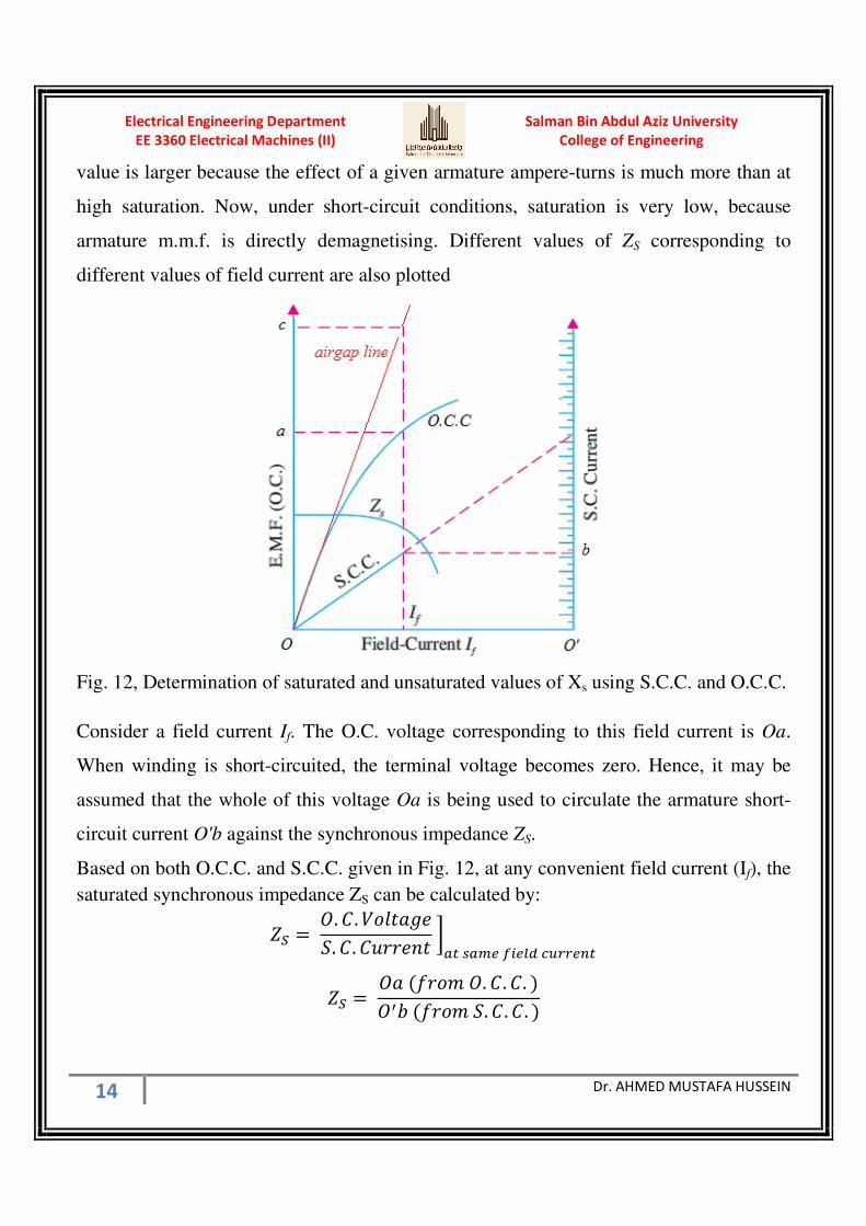
Salman Bin Abdul Aziz University
College of Engineering
Electrical Engineering Department
EE 3360 Electrical Machines (II)
14 Dr. AHMED MUSTAFA HUSSEIN
value is larger because the effect of a given armature ampere-turns is much more than at
high saturation. Now, under short-circuit conditions, saturation is very low, because
armature m.m.f. is directly demagnetising. Different values of ZS corresponding to
different values of field current are also plotted
Fig. 12, Determination of saturated and unsaturated values of Xs using S.C.C. and O.C.C.
Consider a field current If. The O.C. voltage corresponding to this field current is Oa.
When winding is short-circuited, the terminal voltage becomes zero. Hence, it may be
assumed that the whole of this voltage Oa is being used to circulate the armature short-
circuit current O'b against the synchronous impedance ZS.
Based on both O.C.C. and S.C.C. given in Fig. 12, at any convenient field current (If), the
saturated synchronous impedance ZS can be calculated by:
( = 45. 6. 789:;<=. 6. 6>??<@9 AB C* D*EF GHII*JB
( = 5: K?7L 5. 6. 6. 5MN K?7L =. 6. 6.

Salman Bin Abdul Aziz University
College of Engineering
Electrical Engineering Department
EE 3360 Electrical Machines (II)
15 Dr. AHMED MUSTAFA HUSSEIN
= O( P − P =:9>?:9<Q :8><
The unsaturated synchronous impedance ZS can be calculated by:
( = 45. 6. 789:;<=. 6. 6>??<@9 AB C* D*EF GHII*JB
( = 5R K?7L :S?;:T 8S@<5MN K?7L =. 6. 6.
= O( P − P >@U:9>?:9<Q :8><
The resistive element of the machine can simply be found from the DC test explained
before. Value obtained in this test (Ra) may increase the XS accuracy.
* Notes on this method
The important comment on the determination of saturated and unsaturated values of Xs
using S.C.C. and O.C.C. is as follows;
Ef is taken from the OCC whereby the core would be partially saturated for large field
currents, while Ia is taken from the SCC where the core is not saturated at all field
currents. Therefore Ef value taken during the OCC may not be the same Ef value in the
SCC test. Hence the value of XS is only an approximate.
Hence to gain better accuracy, the test should be done at low field currents which looks at
the linear region of the OCC test.
Example 1
From the following tests, determine the synchronous reactance, assuming Ra is 0.8Ω.
S.C.C: a current of 100 A is produced on short-circuit by a field excitation of 2.5A.
O.C.C: An e.m.f. of 500 V is produced on open-circuit by the same excitation.
( = 500100 = 5 Ω
= O( P − P = √5P − 0.8P = 4.936 Ω (Saturated value)

Salman Bin Abdul Aziz University
College of Engineering
Electrical Engineering Department
EE 3360 Electrical Machines (II)
16 Dr. AHMED MUSTAFA HUSSEIN
7.5 Short Circuit Ratio (SCR)
SCR is defined as the ratio of the field current required for the rated voltage at open
circuit to the field current required for rated armature current at short circuit. Based on
Fig. 13, the SCR can be obtained as:
=6 = 5K′5K′′ The saturated synchronous reactance (in per unit) can be calculated as the inverse of SCR
U:9>?:9<Q S@ XY = 1=6 = 5K′′5K′
Fig. 13, Short Circuit Ratio (S.C.R.)
Example 2
The following data are taken from the open- and short-circuit characteristics of a 45 kVA,
3-ph, Y-connected, 220 (line-to-line), 6-poles, 60 Hz synchronous machine:
OCC: line-to-line voltage = 220 V & Field current = 2.84 A
SCC: Armature Current = 118 A & Field current = 2.2 A
Air-gap line: line-to-line voltage = 202 V & Field current = 2.2 A
Calculate the SCR and Compute the saturated and unsaturated value of synchronous
reactance at rated voltage in Ohms and in per unit.

Salman Bin Abdul Aziz University
College of Engineering
Electrical Engineering Department
EE 3360 Electrical Machines (II)
17 Dr. AHMED MUSTAFA HUSSEIN
Va (rated) =220 Line-to-line → from OCC, the corresponding field current = 2.84 A
Ia (rated) = Z[\\\√] PP\ = 118 ' → from SCC, the corresponding field current = 2.2 A
SCR = P.^ZP.P = 1.29
XS (Saturated) = 1/SCR = 1/1.29 = 0.775 P.U.
_:U< = `abcdefabcde = PP\/√]gg^ = 1.0764 Ohm
XS (Saturated) = 0.775 * 1.0764 = 0.8342 Ohm
From SCC, at Field Current of 2.2 A gives armature current of 118 A
From Air-gap Line, at Field Current of 2.2 A gives armature voltage of 116.6 V/phase
XS (unsaturated) = 116.6/118 = 0.988 Ohm
XS (unsaturated) = 0.988/1.0764 = 0.918 P.U.
Example (3)
A 200 kVA, 480-V, 60-Hz, 4-pole, Y-Connected synchronous generator with a rated field
current of 5 A was tested and the following data was taken.
a) from OC test – terminal voltage = 540 V at rated field current
b) from SC test – line current = 300A at rated field current
c) from DC test – DC voltage of 10 V applied to two terminals, a current of 25 A was
measured.
1. Calculate the speed of rotation in rpm
2. Calculate the saturated equivalent circuit parameters (armature resistance and
synchronous reactance) in Ohms and PU.
Vrated = 480/√3 = 277.13 V and Ia rated = 200000/(√3 * 480) = 240.56 A
Zbase = Vrated / Ia rated = 277.13 / 240.56 = 1.152 Ω
The synchronous speed ns = 60 f / P = 60*60/2 = 3600/2 = 1800 rpm
From DC Test
RDC = 10/25 = 0.4 Ω
Salman Bin Abdul Aziz University
College of Engineering
Electrical Engineering Department
EE 3360 Electrical Machines (II)
18 Dr. AHMED MUSTAFA HUSSEIN
Ra = (0.4/2)*1.15 = 0.23 Ω
Ra = 0.23 / 1.152 = 0.2 PU.
From OC Test
Rated field current produce rated voltage of 540/√3 = 311.77 V
From SC Test
Rated field current produce rated current = 300 A
Saturated ZS = 311.77/300 = 1.04 Ω
Saturated ZS = 1.04 / 1.152 = 0.903 PU.
Xs = O( P − P = √1.04P − 0.23P = 1.0287 Ω
= g.\P^hg.g[P = 0.893 PU.
7.6 Obtaining the phasor diagram from OCC and SCC at saturation condition
In case of saturation, Xs is variable (unknown). But all information to calculate Er is
given, therefore,
Er = V + Ia(Ra + j XL)
From OCC at Er we get the corresponding Fr which is perpendicular to Er and lead by 90
from SCC at Ia find the corresponding Fa
Fa is drawn in the same direction of Ia
Since Fr = Ff + Fa, we can obtain Ff
Again from OCC at the value of Ff, we can obtain Ef
The direction of Ef is perpendicular to Ff and lag by 90
These steps are given in Fig. 14.

Salman Bin Abdul Aziz University
College of Engineering
Electrical Engineering Department
EE 3360 Electrical Machines (II)
19 Dr. AHMED MUSTAFA HUSSEIN
Fig. 14, Phasor diagram from OCC and SCC
7.7 Voltage regulation
It is clear that with change in load, there is a change in terminal voltage of an alternator.
The magnitude of this change depends not only on the load but also on the load power
factor. The voltage regulation of an alternator is defined as “the rise in voltage when full-
load is removed (field excitation and speed remaining the same) divided by the rated
terminal voltage.”
Er Ia XL
φ V
Ia
Fr
Fa
Ff
direction of Ef

Salman Bin Abdul Aziz University
College of Engineering
Electrical Engineering Department
EE 3360 Electrical Machines (II)
20 Dr. AHMED MUSTAFA HUSSEIN
In case of lagging and unity power factors, the regulation is positive (up)
% ?<;>8:9S7@ >T = −
In case of leading power factor, the regulation is negative (down).
% ?<;>8:9S7@ Q7j@ = −
Example 4
A 1000 kVA, 3300-V, 3-phase, star-connected alternator delivers full-load current at
rated voltage at 0.80 p. f. Lagging. The resistance and synchronous reactance of the
machine per phase are 0.5 ohm and 5 ohms respectively. Estimate the terminal voltage
for the same excitation and same load current at 0.80 p. f. leading.
In case of lagging power factor
Rated phase voltage (V) = 3300/√3 = 1905.26 volt
Rated phase current (Ia) = g\\\×g\k√]×]]\\ 174.95 Amp.
IaRa = 174.95*0.5 = 87.475 volt
IaXS = 174.95*5.0 = 874.75 volt
Component of Ef along the horizontal axis OD = OA + AB’ + B’D
OD = V + AB cos(φ) + BC sin(φ) = 1905.26 + 87.475*0.8 + 874.75*0.6 = 2500.09
Component of Ef along the vertical axis DC = BC cos(φ) – AB sin(φ)
DC = 874.75*0.8 – 87.475*0.6 = 647.315
Ef = √2500.09P + 647.315P = 2582.53 volt
Load angle δ = 9:@lg 23m2 = 9:@lg "Zh.]g[P[\\.\n = 14.52
Salman Bin Abdul Aziz University
College of Engineering
Electrical Engineering Department
EE 3360 Electrical Machines (II)
21 Dr. AHMED MUSTAFA HUSSEIN
In case of leading power factor
Since the excitation is kept constant, this means Ef is the same in magnitude, and the
alternator delivering rated current at 0.80 leading p.f., the phasor diagram is to be drawn
to evaluate V.
Construction of the phasor diagram starts with marking the reference. Take a point A
which is the terminating point of phasor V which starts from O. Point O is the point yet to
be marked, for which the other phasors have to be drawn. Draw AB parallel to the current
Ia. Then draw BC perpendicular to AB. From C, draw an arc of length E, i.e. 2582.53
volts to intersect with the reference line (ref) to locate O. Therefore the terminal voltage
OA represents the terminal voltage (V).
AB = IaRa = 87.475 volt with angle 36.8 and BC = IaXS = 874.75 volt ⊥ Ia
From the phasor diagram, V = 2925 Volt
Example 5.
The following test results were obtained on a 275-kW, 3-ph, 6600-V non-salient pole type
generator. Open-circuit characteristic :
Phase Voltage (V) 3233 3810 4180 4677
Field Current (A) 46.5 58 67.5 96
Short-circuit characteristic : Stator current 35 A with an exciting current of 50 A.
Leakage reactance drop on full-load = 8%.
Neglect armature resistance. Calculate as accurately as possible the exciting current (for
full-load) at power factor 0.8 lagging.

Salman Bin Abdul Aziz University
College of Engineering
Electrical Engineering Department
EE 3360 Electrical Machines (II)
22 Dr. AHMED MUSTAFA HUSSEIN
Rated phase voltage Va = 6600/√3 = 3810.5 V.
Rated Current Ia = 275*103 / (3*3810.5*0.8) = 30 A
IaXL = 8% = 0.08 P.U. = 0.08 * 3810.5 = 304.8 V
Fig. 15, OCC and SCC of example 5
From the phasor diagram shown in Fig. 16, draw the rated voltage as a reference OA.
Then draw IaXL = 308.4 V ⊥ Ia and represented by the length AB. The resultant voltage
Er can be obtained graphically by the length OB = 4010 V.
Fig. 16, phasor diagram of example 5
From the OCC shown in Fig. 16, at voltage of 4010, we can get Fr = 62 A and
represented by OC ⊥ OB

Salman Bin Abdul Aziz University
College of Engineering
Electrical Engineering Department
EE 3360 Electrical Machines (II)
23 Dr. AHMED MUSTAFA HUSSEIN
From the SCC, shown in Fig. 15, at full load current of 30 A, the corresponding field
current Fa = 43 A that is represented by the line DC // Ia and in the same direction.
From the MMF triangle ODC, the value of Ff that is represented by OD = 94.3 A
7.8. Zero Power Factor Test or Potier Triangle Method
This method is based on the separation of armature-leakage reactance XL and the
armature reaction effects Xa. Hence, it gives more accurate results. The experimental data
required is
(i) No-load curve Or O.C.C. and
(ii) Full-load, zero-power factor curve (Z.P.F.C), also called wattless load
characteristic. It is the curve of terminal volts against excitation when armature is
delivering F.L. current at zero p.f. (when loaded by a pure inductive load for
example). Both OCC & ZPFC are shown in Fig. 15.
Point A, at which (V=0) and the current flow is the full load current, on Z.P.F.C is
obtained from a short-circuit test with full-load armature current. Hence, OA represents
field current which is equal and opposite to the demagnetising armature reaction and for
balancing leakage reactance drop at full-load.
From B, draw BH equal to and parallel to OA. From H, HD is drawn parallel to the air
gap line OC. Hence, we get point D on the O.C.C. curve. Connect the two points DB to
get the triangle BHD which is known as Potier triangle. This triangle is constant for a
given armature current and hence can be transferred to give us other points like M, L etc.
Draw DE perpendicular to BH. The length DE represents the voltage drop due to
armature leakage reactance XL i.e. IaXL. BE gives field current necessary to overcome
demagnetising effect of armature reaction at full load and EH for balancing the armature
leakage reactance drop DE.

Salman Bin Abdul Aziz University
College of Engineering
Electrical Engineering Department
EE 3360 Electrical Machines (II)
24 Dr. AHMED MUSTAFA HUSSEIN
Fig. 17, Potier Triangle
Let V be the terminal voltage on full-load, then if we add to it vectorially the voltage drop
due to armature leakage reactance alone (neglecting Ra), then we get voltage Er = DF.
Obviously, field excitation corresponding to Er is given by OF. NA ( = BE) represents the
field current needed to overcome armature reaction. Hence, if we add NA vectorially to
OF, we get excitation(OJ) required to produce Ef whose value from O.C.C curve (JK).
Example 6.
A 3-phase, 6000-V alternator has the following O.C.C. at normal speed:
Field Current (A) 14 18 23 30 43
Terminal Voltage (V) 4000 5000 6000 7000 8000
With armature short-circuited and full-load current flowing, the field current is 17 A.
Also when the machine is supplying full-load of 2,000 kVA at zero power factor, the field
current is 42.5 A and the terminal voltage is 6000 V.
Determine the field current required when the machine is supplying the full-load at 0.8
p.f. lagging. The O.C.C. at phase voltage is
Field Current (A) 14 18 23 30 43
Phase Voltage (V) 2309.4 2886.75 3464.1 4041.45 4618.8

Salman Bin Abdul Aziz University
College of Engineering
Electrical Engineering Department
EE 3360 Electrical Machines (II)
25 Dr. AHMED MUSTAFA HUSSEIN
We have two points on Z.P.F.C,
Field Current (A) 17 42.5
Phase Voltage (V) 0 3464.1
Fig. 18 OCC and ZPFC for example 6
From both the OCC and ZPFC we can obtain Potier triangle BHD as shown in Fig. 18.
From Potier triangle, DE represents IaXL = 450 V.
From the phasor diagram shown in Fig. 19, we can obtain Er graphically (OB) or
mathematically as:
I = o + psin P + pcos P
I = o3464.1 + 450 × 0.6P + 450 × 0.8P = 3751.41
From the OCC at 3751 V, we get the corresponding field current (Fr) of 26.5 A.
This field current (OC = 26.5) is drawn ⊥ OB
From Potier triangle we can get the field current (Fa corresponding to IaXa) which is BE =
14.5 A. This value is drawn in Fig. 19 as the length DC parallel to the armature current
and in the same direction.

Salman Bin Abdul Aziz University
College of Engineering
Electrical Engineering Department
EE 3360 Electrical Machines (II)
26 Dr. AHMED MUSTAFA HUSSEIN
Therefore, from the MMF triangle ODC, the field current (Ff) OD = 37.2 A.
Fig. 19, Phasor diagram of example 6
Example 7.
An 11-kV, 1000-kVA, 3-phase, Y-connected alternator has a resistance of 2 Ω per phase.
The open-circuit and full-load zero power factor characteristics are given below.
Find the voltage regulation of the alternator for full load current at 0.8 p.f. lagging by
Potier method.
Field Current (A) 40 50 110 140 180
OCC line voltage 5800 7000 12500 13750 15000
ZPF line voltage 0 1500 8500 10500 12500
The phase voltages used in OCC and ZPFC are as in the following table
Field Current (A) 40 50 110 140 180
OCC phase voltage 3348.63 4041.45 7216.88 7938.57 8660.25
ZPF phase voltage 0 866 4907.48 6062.18 7216.88
The full-load current Ia = 1000*103 /(√3 * 11*10
3) = 52.49 A
Phase voltage Va = 11*103 / √3 = 6350.85 V
Salman Bin Abdul Aziz University
College of Engineering
Electrical Engineering Department
EE 3360 Electrical Machines (II)
27 Dr. AHMED MUSTAFA HUSSEIN
Fig. 20, Potier triangle of example 7
Potier triangle ACB is drawn as shown in Fig. 20. Where AC = 40 A. CB is drawn
parallel to the air gap line. BD ⊥ AC.
BD, the leakage reactance drop IaXL = BD = 1000 V (by measurement)
AD = 30 A (armature reaction Fa)
We draw the phasor diagram of the alternator at 0.8 pf lag as shown in Fig. 18.
Fig. 21, Phasor diagram of example 7

Salman Bin Abdul Aziz University
College of Engineering
Electrical Engineering Department
EE 3360 Electrical Machines (II)
28 Dr. AHMED MUSTAFA HUSSEIN
Draw IaRa = 52.49*2 = 105 V represented by the length AB // Ia
Then draw IaXL = 1000 V represented by the length BC ⊥ Ia
Graphically, we can obtain the air gap voltage Er = 7080 V
From OCC at 7080 V, the corresponding field current (Fr) is 108 A that is drawn ⊥ Er as
the line OD in Fig. 21.
From potier triangle Fa = 30 A and represented by the line FD // Ia and in the same
direction.
From the MMF triangle OFD, the length OF that represent Ff is obtained = 128 A.
From the OCC at field current = 128, the corresponding voltage (Ef) = 7700 V.
<;>8:9S7@>T = − = 7700 − 63506350 = 0.2126 = 21.26%
Note: in example 5, the field excitation of 43 A is assumed to be used for balancing
armature reaction Fa. In fact, a part of this value is used for balancing armature leakage
drop of 304.8 V as explained in the Potier triangle method. Therefore, this is considered
as inaccurate solution.
8. Synchronous Motor
A synchronous motor, shown in Fig. 22, is electrically identical with an alternator or AC
generator. In fact, a given synchronous machine may be used, at least theoretically, as an
alternator, when driven mechanically or as a motor, when driven electrically, just as in
the case of DC machines. Most synchronous motors are rated between 150 kW and 15
MW and run at speeds ranging from 150 to 1800 r.p.m.
The following characteristic features of a synchronous motor:
1. It runs either at synchronous speed or not at all i.e. while running it maintains a
constant speed. The only way to change its speed is to vary the supply frequency.
2. It is not inherently self-starting. It has to be run up to synchronous (or near
synchronous) speed by some means, before it can be synchronized to the supply.

Salman Bin Abdul Aziz University
College of Engineering
Electrical Engineering Department
EE 3360 Electrical Machines (II)
29 Dr. AHMED MUSTAFA HUSSEIN
3. It is capable of being operated under a wide range of power factors, both lagging and
leading. Hence, it can be used for power correction purposes, in addition to supplying
torque to drive loads.
Fig. 22, Synchronous motor
8.1 Principle of Operation
when a 3-φ armature winding is fed by a 3-φ supply, then a magnetic flux of constant
magnitude but rotating at synchronous speed, is produced. Consider a synchronous motor
shown in Fig. 23, in which the stator has two poles (for simplicity) marked NS and SS and
rotating at synchronous speed in clockwise direction. At certain instant, assume the
position of the stator poles are situated at points A and B With the rotor poles marked N
and S are located at the position shown in Fig. 24-a. The rotor and stator poles will repel
each other, with the result that the rotor tends to rotate in the anticlockwise direction.
Half a period later, stator poles, having rotated around, interchange their positions i.e. NS
is at point B and SS at point A as shown in Fig. 24-b. Under these conditions, NS attracts S

Salman Bin Abdul Aziz University
College of Engineering
Electrical Engineering Department
EE 3360 Electrical Machines (II)
30 Dr. AHMED MUSTAFA HUSSEIN
and SS attracts N. Hence, rotor tends to rotate clockwise (which is just the reverse of the
first direction). Hence, we find that due to continuous and rapid rotation of stator poles,
the rotor is subjected to a torque which is rapidly reversing i.e., in quick succession, the
rotor is subjected to torque which tends to move it first in one direction and then in the
opposite direction. Owing to its large inertia, the rotor cannot instantaneously respond to
such quickly-reversing torque, with the result that it remains stationary.
Fig. 23, Two-pole, synchronous motor
(a) (b) (c)
Fig. 24, Rotor poles with respect to stator poles

Salman Bin Abdul Aziz University
College of Engineering
Electrical Engineering Department
EE 3360 Electrical Machines (II)
31 Dr. AHMED MUSTAFA HUSSEIN
Suppose that the rotor is not stationary, but is rotating clockwise with synchronous speed.
Here, again the stator and rotor poles attract each other. It means that if the rotor poles
also shift their positions along with the stator poles, then they will continuously
experience a unidirectional torque i.e., clockwise torque, as shown in Fig. 24-c.
Therefore, the rotor (which is as yet unexcited) is speeded up to synchronous or near
synchronous speed by some arrangement and then excited by DC source. The moment
this (near) synchronously rotating rotor is excited, it is magnetically locked into position
with the stator i.e., the rotor poles are engaged with the stator poles and both run
synchronously in the same direction. It is because of this interlocking of stator and rotor
poles that the motor has either to run synchronously or not at all.
However, it is important to understand that the arrangement between the stator and rotor
poles is not an absolutely rigid one. As the load on the motor is increased, the rotor
progressively tends to fall back in phase (but not in speed as in DC motors) by some
angle (as shown in Fig. 25) but it still continues to run synchronously. The value of this
load angle depends on the amount of load to be met by the motor. In other words, the
torque developed by the motor depends on this angle, δ.
Fig. 25, Effect of increased loads on the load angle σ
Salman Bin Abdul Aziz University
College of Engineering
Electrical Engineering Department
EE 3360 Electrical Machines (II)
32 Dr. AHMED MUSTAFA HUSSEIN
8.2 Phasor Diagrams
The synchronous motor based on its equivalent circuit shown in Fig. 3-b, can be
represented by the following equation:
= +
From the phasor diagram shown in Fig.26, it is clear that the synchronous motor acts as
an electric load with lagging power factor and Ef < V (Under Excited motor).
From the phasor diagram shown in Fig. 27, it is clear that the synchronous motor acts as
an electric load with leading power factor and Ef > V (Over Excited motor).
Also the load angle between Ef and V which called δ is always negative value.
Ra is considered Ra is not considered
Fig. 26, Under-Excited Synchronous motor (Lagging power factor)
Ef
Ia XL φ
V
δ
Ia
Ia Ra Er
Ia Xa
Ef Er
Fr
Ff
Fa

Salman Bin Abdul Aziz University
College of Engineering
Electrical Engineering Department
EE 3360 Electrical Machines (II)
33 Dr. AHMED MUSTAFA HUSSEIN
Ra is considered Ra is not considered
Fig. 27, Over-Excited synchronous motor (Leading power factor)
Ra is considered Ra is not considered
Fig. 28, Over-Excited synchronous motor (Unity power factor)
Summary of this point:
The load angle δ is always negative.
Also, it is seen from the MMF triangle that Fr is always leading Ff
If field excitation is such that Ef < V, the motor is said to be under-excited. This
happened at a lagging power factor as shown in Fig. 26. From this figure we notice that
Fa support Ff and produce larger Fr
V
-Ef
Ia XL φ
δ
Ia
Ia Ra
Ia Xa
-Er
Ef
Er
Fr
Fa
Ff

Salman Bin Abdul Aziz University
College of Engineering
Electrical Engineering Department
EE 3360 Electrical Machines (II)
34 Dr. AHMED MUSTAFA HUSSEIN
On the other hand, if DC field excitation is such that Ef > V, then motor is said to be
over-excited and draws a leading current, as shown in Fig. 27. From this figure we notice
that Fa Oppose Ff and produce smaller Fr
Moreover, the over-excited condition can be obtained at unity power factor as well as
shown in Fig. 28.
Example 8.
A 3-Phase synchronous motor is worked on rated values of 400 V/Ph, 32 A/Ph, and Unity
p.f. XS = 10 ohms. Neglecting the value of Ra, calculate Ef and δ.
The terminal voltage (V) = OA = 400 volt
IaXS = AB = 32 * 10 = 320 volt
From phasr diagram, the excitation voltage Ef = √400P 320P = 512.25 volt
The load angle or torque angle (δ) = tan-1
(320/400) = 38.66 (negative value)
8.3 Analytical Representation of Phasor Diagram
Consider the phasor diagram of 3-ph synch. motor at lagging p.f. as shown in Fig. 29-(a).
Fig. 29-(a), Synch. Motor phasor diagram at lagging p.f
Ef Ia Xs
φ φ
V
δ
Ia Ia Ra φ
Salman Bin Abdul Aziz University
College of Engineering
Electrical Engineering Department
EE 3360 Electrical Machines (II)
35 Dr. AHMED MUSTAFA HUSSEIN
We can describe this phasor diagram by two equations:
Horizontal Analysis:
cos cos sin… 1 Vertical Analysis:
sin cos sin… 2 By dividing (2) over (1), we obtain:
tan cos sin cos sin
Once the angle () is known, we can obtain the excitation voltage Ef.
Now, if Ra is neglected, the phasor diagram is shown in Fig. 29-(b).
Fig. 29(b), Approximate phasor at lag p.f
Equations (1) and (2) can be rewritten by replacing Ra=0 as:
Horizontal Analysis:
cos sin… 3 Vertical Analysis:
sin cos… 4 By dividing (4) over (3), we obtain:
tan cos sin… 5
Once the angle () is known, we can obtain the excitation voltage Ef.
Ef
Ia Xs φ
φ
V
δ
Ia

Salman Bin Abdul Aziz University
College of Engineering
Electrical Engineering Department
EE 3360 Electrical Machines (II)
36 Dr. AHMED MUSTAFA HUSSEIN
By the same way, we can describe the phasor diagram in case of leading power factor
given in Fig. 30-(a) by two equations:
Fig. 30-(a), Synch. Motor phasor diagram at leading p.f
Horizontal Analysis:
cos sin cos… 6 Vertical Analysis:
sin cos sin… 7 By dividing (7) over (6), we obtain:
tan cos sin sin cos
Once the angle () is known, we can obtain the excitation voltage Ef.
Now, if Ra is neglected, the phasor diagram is shown in Fig. 30(b).
Fig. 30-b, Approximate phasor at lead p.f
Equations (6) and (7) can be rewritten by replacing Ra=0 as:
V
Ef Ia Xs
φ
φ
δ
Ia
φ
Ia Ra
Ef
Ia Xs
φ
φ
V
δ
Ia
Salman Bin Abdul Aziz University
College of Engineering
Electrical Engineering Department
EE 3360 Electrical Machines (II)
37 Dr. AHMED MUSTAFA HUSSEIN
Horizontal Analysis:
cos = + sin … 8
Vertical Analysis:
sin = cos … 9
By dividing (9) over (8), we obtain:
tan = cos + sin
Once the angle () is known, we can obtain the excitation voltage Ef.
From the explained phasor diagrams given in Figs 26 to 30, we notice that Ef is always
behind V, this means the power angle (δ) is always negative, and this is the remarkable
notice on the phasor diagram of synchronous motors.
9. Power Flow within a Synchronous Machines
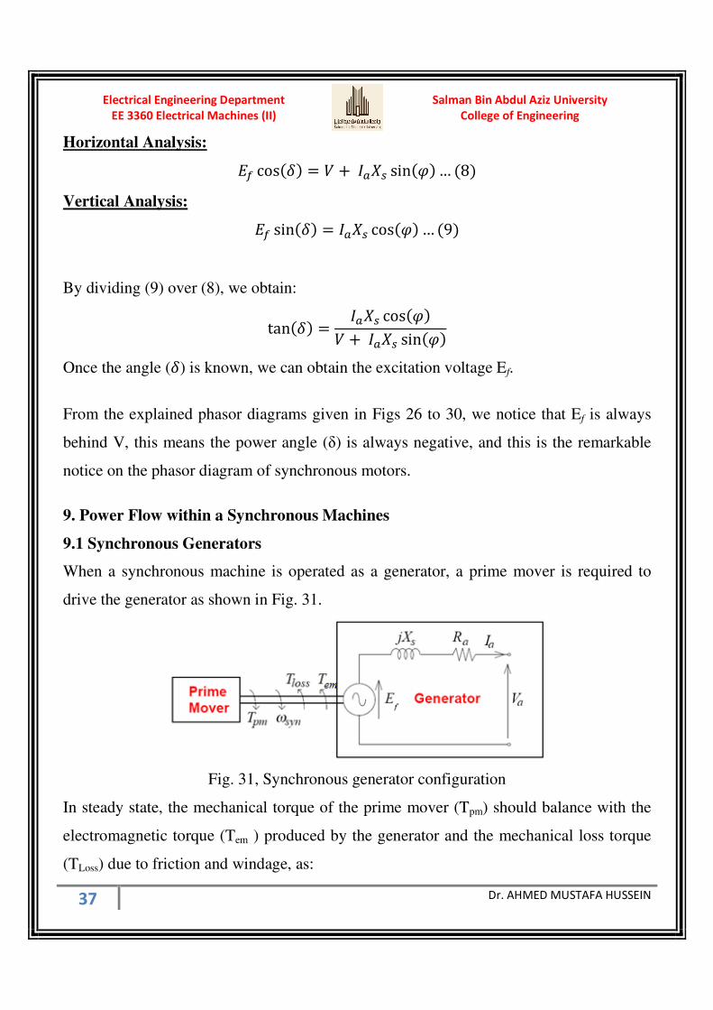
9.1 Synchronous Generators
When a synchronous machine is operated as a generator, a prime mover is required to
drive the generator as shown in Fig. 31.
Fig. 31, Synchronous generator configuration
In steady state, the mechanical torque of the prime mover (Tpm) should balance with the
electromagnetic torque (Tem ) produced by the generator and the mechanical loss torque
(TLoss) due to friction and windage, as:

Salman Bin Abdul Aziz University
College of Engineering
Electrical Engineering Department
EE 3360 Electrical Machines (II)
38 Dr. AHMED MUSTAFA HUSSEIN
q+C = q*C + qEr
Multiplying the synchronous speed to both sides of the torque equation, we have the
power balance equation as
X+C = X*C + XEr
Where Ppm is Prime Mover power or the total mechanical power input to the generator or
called the Gross Mechanical power = ωsynTpm
Ploss is the mechanical power loss or the friction and windage loss = ωsynTloss
Pem is the electromagnetic power that converted to electrical power = ωsynTem
Pem = ωsynTem = 3 Ef Ia cos(φ + δ) in case of Lagging P.F.
Pem = ωsynTem = 3 Ef Ia cos(φ - δ) in case of Leading P.F.
Taking the iron loss power (Piron) and the armature cupper loss (Pcu), we can get the
electrical output power (Pout). The power flow of alternators is shown in Fig. 32.
Pout = 3 Va Ia cos(φ)
Fig. 32, Power flow in a synchronous generator
As we know, in case of generator
= + +
The value of XS is much bigger compared to the value of Ra, so Ra can be neglected.
= +
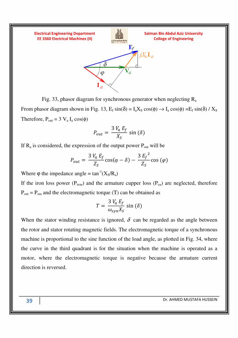
That can be represented by the phasor diagram shown in Fig. 33.
Salman Bin Abdul Aziz University
College of Engineering
Electrical Engineering Department
EE 3360 Electrical Machines (II)
39 Dr. AHMED MUSTAFA HUSSEIN
Fig. 33, phasor diagram for synchronous generator when neglecting Ra
From phasor diagram shown in Fig. 13, Ef sin(δ) = IaXS cos(φ) → Ia cos(φ) =Ef sin(δ) / XS
Therefore, Pout = 3 Va Ia cos(φ)
XrHB = 3 sin
If Ra is considered, the expression of the output power Pout will be
XrHB = 3 ( cosϕ − − 3 P( cos
Where ϕ the impedance angle = tan-1
(XS/Ra)
If the iron loss power (Piron) and the armature cupper loss (Pcu) are neglected, therefore
Pout = Pem and the electromagnetic torque (T) can be obtained as
q = 3 stJ sin
When the stator winding resistance is ignored, δ can be regarded as the angle between
the rotor and stator rotating magnetic fields. The electromagnetic torque of a synchronous
machine is proportional to the sine function of the load angle, as plotted in Fig. 34, where
the curve in the third quadrant is for the situation when the machine is operated as a
motor, where the electromagnetic torque is negative because the armature current
direction is reversed.

Salman Bin Abdul Aziz University
College of Engineering
Electrical Engineering Department
EE 3360 Electrical Machines (II)
40 Dr. AHMED MUSTAFA HUSSEIN
Fig. 34, T-δ relationship
9.2 Synchronous Motor
When a synchronous machine is operated as a motor to drive a mechanical load as shown
in Fig. 35, in steady state, the mechanical torque of the motor should balance the load
torque and the mechanical loss torque due to friction and windage, that is
q*C = qprF + qEr
Multiplying the synchronous speed to both sides of the torque equation, we have the
power balance equation as
X*C = XprF + XEr
Fig. 35, Synchronous motor configuration
Similar to the case of a generator, the electromagnetic power is the amount of power
being converted from the electrical into the mechanical power. That is
Pem = ωsynT = 3 Ef Ia cos(δ - φ) in case of Lagging P.F.
Pem = ωsynT = 3 Ef Ia cos(δ + φ) in case of Leading P.F.

Salman Bin Abdul Aziz University
College of Engineering
Electrical Engineering Department
EE 3360 Electrical Machines (II)
41 Dr. AHMED MUSTAFA HUSSEIN
Fig. 36, phasor diagram for synchronous motor when Ra is neglected
From the phasor diagram shown in Fig. 36, Ef cos(δ - φ) = Va cos(φ)
Also, Ef sin(δ) = IaXS cos(φ)
Therefore, the electromagnetic power can be expressed as
X*C = 3 sin
q = 3 stJ sin
The T-δ relationship for the synchronous motor is shown in Fig. 34 (Third Quadrant).
The input electrical power to the motor is Pin = 3 Va Ia cos(φ)
Taking the armature copper loss (Pcu) and the iron loss (Piron) to get the electromagnetic
power Pem as shown in the power flow shown in Fig. 37.
Fig. 37, power flow in synchronous motor
10.1 Different Torques of a Synchronous Motor
Various torques associated with a synchronous motor are as follows:

Salman Bin Abdul Aziz University
College of Engineering
Electrical Engineering Department
EE 3360 Electrical Machines (II)
42 Dr. AHMED MUSTAFA HUSSEIN
1. Starting torque (developed by the motor at starting)
2. Running torque (developed by the motor at the running conditions)
3. Pull-in torque (A synchronous motor is started as induction motor till it runs at 2 to 5%
below the synchronous speed. Afterwards, excitation is switched on and the rotor
pulls into step with the synchronously rotating stator field. The amount of torque at
which the motor will pull into step is called the pull-in torque.
4. Pull-out torque (The maximum torque that the motor can develop without pulling out
of synchronism)
To get the Pull-out Torque, we get the maximum power then divide by the synchronous
speed. If Ra is neglected; the max. power obtained at δ = 90 as shown in Fig. 38
X*CCu = 3 sin90 = 3
Fig. 38, Maximum (Pull-out) torque
If Ra is not neglected, therefore to get the maximum power is at dPem/dδ = 0 QX*CQ = − 3 ( sinv − = 0
This occurred at δ = θ
Example:
A 75-kW, 3-φ, Y-connected, 50-Hz,4-pole, 440-V cylindrical rotor synchronous motor
operates at rated condition with 0.8 p.f. leading. The motor efficiency is 95% and XS =
2.5 Ω. Calculate (i) input power (ii) armature current (iii) back e.m.f. (iv) power angle
(v) electromagnetic power (vi) maximum or pull-out torque of the motor.
Salman Bin Abdul Aziz University
College of Engineering
Electrical Engineering Department
EE 3360 Electrical Machines (II)
43 Dr. AHMED MUSTAFA HUSSEIN
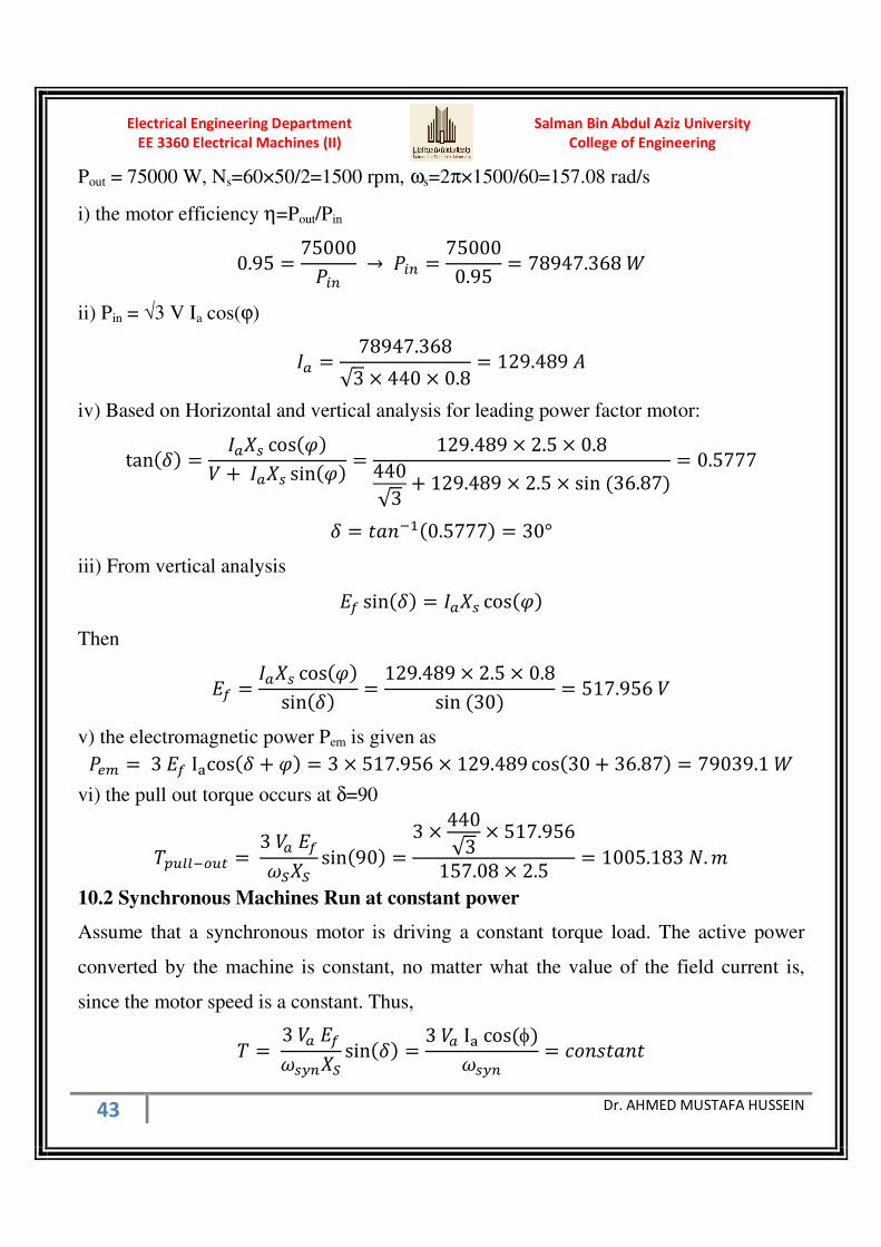
Pout = 75000 W, Ns=60×50/2=1500 rpm, ωs=2π×1500/60=157.08 rad/s
i) the motor efficiency η=Pout/Pin
0.95 = 75000XDJ → XDJ = 750000.95 = 78947.368 w
ii) Pin = √3 V Ia cos(ϕ)
= 78947.368√3 × 440 × 0.8 = 129.489 '
iv) Based on Horizontal and vertical analysis for leading power factor motor:
tan = cos + sin = 129.489 × 2.5 × 0.8440√3 + 129.489 × 2.5 × sin 36.87 = 0.5777
= 9:@lg0.5777 = 30°
iii) From vertical analysis
sin = cos
Then
= cossin = 129.489 × 2.5 × 0.8sin 30 = 517.956
v) the electromagnetic power Pem is given as X*C = 3 Izcos + = 3 × 517.956 × 129.489 cos30 + 36.87 = 79039.1 w
vi) the pull out torque occurs at δ=90
q+HEElrHB = 3 s sin90 = 3 × 440√3 × 517.956157.08 × 2.5 = 1005.183 . L
10.2 Synchronous Machines Run at constant power
Assume that a synchronous motor is driving a constant torque load. The active power
converted by the machine is constant, no matter what the value of the field current is,
since the motor speed is a constant. Thus,
q = 3 stJ sin = 3 Iz cosφstJ = R7@U9:@9

Salman Bin Abdul Aziz University
College of Engineering
Electrical Engineering Department
EE 3360 Electrical Machines (II)
44 Dr. AHMED MUSTAFA HUSSEIN
sin = cosφ = R7@U9:@9
Using the phasor diagram shown in Fig. 39, we analyze the variation of the power factor
angle of a synchronous motor when the field excitation is varied. Both Ef and Ia can only
be able to vary along the horizontal and the vertical dotted lines.
Fig. 39, Synchronous Motor driving constant load
For a small rotor field current (under excited), the induced emf shown by the phasor Ef1.
This yields a lagging power factor angle φ1.
As the excitation current increases (over excited), the lagging power factor angle is
reduced. At a certain rotor current, the induced emf given by phasor Ef2 is perpendicular
to the terminal voltage phasor, and hence the stator current phasor is aligned with the
terminal voltage, that is a zero power factor angle φ2 = 0.
When the rotor current further increases (over excited), the stator current leads the
terminal voltage, or a leading power factor angle φ3.
In practice, because of this feature, synchronous motors are often run at no active load as
synchronous condensers for the purpose of power factor correction. The diagram shown
in Fig. 40, illustrates schematically the power factor compensation for an inductive load,
which is common for factories using large induction motor drives, using a synchronous
condenser. By controlling the rotor excitation current such that the synchronous
condenser draws a line current of leading phase angle, whose imaginary component

Salman Bin Abdul Aziz University
College of Engineering
Electrical Engineering Department
EE 3360 Electrical Machines (II)
45 Dr. AHMED MUSTAFA HUSSEIN
cancels that of the load current, the total line current would have a minimum imaginary
component. Therefore, the overall power factor of the inductive load and the synchronous
condenser would be close to one and the magnitude of the overall line current would be
the minimum.
Fig. 40, Over-excited synchronous motor for P.F. improvement
It can also be seen that only when the power factor is unity or the stator current is aligned
with the terminal voltage, the magnitude of the stator current is minimum.
Example:
A synchronous motor absorbing 60 kW is connected in parallel with a factory load of 240
kW having a lagging p.f. of 0.8. If the combined load has a p.f. of 0.9, what is the value
of the leading kVAR supplied by the motor and at what p.f. is it working ?
PMotor = 60 kW
PFactory = 240 kW, QFactory = 240000×tan(36.87)=180 kVAR

Salman Bin Abdul Aziz University
College of Engineering
Electrical Engineering Department
EE 3360 Electrical Machines (II)
46 Dr. AHMED MUSTAFA HUSSEIN
Pcombined = 240 + 60 = 300 kW
since the P.F. of the combined load is 0.9 lagging, then
Qcombined = 300000×tan(25.84) = 145 kVAR (Lag)
Therefore, Qmotor = 180 - 145.297 = 35 kVAR (Lead)
Motor angle = tan-1
35/60 = 30.3°
Motor P.F. = cos (30.26) = 0.863 lead
When the motor power is kept constant, then by plotting the magnitude of the stator
current against the rotor excitation current at different loading conditions, a family of “V”
curves can be obtained as shown in Fig. 41.
It is shown that a larger rotor field current is required for a larger active load to operate at
unity power factor.
Fig. 40, V-curves of synchronous motor
Example 9.
A 3-phase, 400-V, , Y-connected, 4-pole, cylindrical synchronous generator with
synchronous reactance of 10Ω and negligible armature resistance. For the requirements
Salman Bin Abdul Aziz University
College of Engineering
Electrical Engineering Department
EE 3360 Electrical Machines (II)
47 Dr. AHMED MUSTAFA HUSSEIN
of constant power operation, the value of "Ef sin(σ)" is kept constant at 57.6 V. When
supplying a load with 0.8 p.f. lag, calculate:
a) The excitation voltage (Ef ) and the load angle (σ),
b) The armature current (Ia ).
If the generator is running under constant power condition and the load p.f. is increased
to unity. Calculate the new values of:
c) The excitation voltage (Ef ) and the load angle (σ),
d) The armature current (Ia ).
Graphical Solution
Assuming the voltage scale is each 10 V is represented by 1 cm
Va = 400/√3 = 230.94 V = 23.1 cm and represented by line OA
The current direction is OB at angle φ = 36.9 lag
Draw the line CD parallel to Va at a distance Ef sin(σ) is constant = 57.6 V = 5.8 cm
Draw a line OB and intersect with CD in point G
Measure OG that represents the excitation voltage Ef = 28 cm = 280 V #####
Measure the angle AOG that represents the load angle (σ) = 12 ####
Measure AG that represents Ia XS = 7.2 cm = 72 V
Ia = AG/XS = 72/10 = 7.2 A ####
Now, the power factor is increased to 1.0
Measure OH that represents the excitation voltage Ef = 23.8 cm = 238 V #####
Measure the angle AOH that represents the load angle (σ) = 14 ####
The drop Ia XS is represented by AH = 5.8 cm = 57.6 V
Ia = AH/XS = 57.6/10 = 5.76 A #####
Analytical Solution
From phasor diagram
Ef sin(σ) = Ia XS cos(φ) ---------------------------------(1)
Ef cos(σ) = Va + Ia XS sin(φ) --------------------------(2)
From (1)

Salman Bin Abdul Aziz University
College of Engineering
Electrical Engineering Department
EE 3360 Electrical Machines (II)
48 Dr. AHMED MUSTAFA HUSSEIN
= sin | cos φ 57.610 × 0.8 7.2 '
From (2)
cos| 230.94 72 sin36.87 274.14
sin | cos | tan| 57.6
274.14 0.210111
| 11.87° sin11.87 57.6
57.6sin 11.87 280.126
Now, the power factor is increased to 1.0
Ia XS = Ef sin(σ) = 57.6 V
Ia = 57.6 / 10 = 5.76 A
o230.94P 57.6P 238.015
| 9:@lg 57.6230.94 14°
Ef1
O
φ
σ
A
B
G
57.6 V
C D
φ
Ef sin(σ)
Ia XS
Ef2
H

Salman Bin Abdul Aziz University
College of Engineering
Electrical Engineering Department
EE 3360 Electrical Machines (II)
49 Dr. AHMED MUSTAFA HUSSEIN
Example:
A 3-phase, Y-connected turbo-alternator, having a synchronous reactance of 10 Ω per
phase and negligible armature resistance, has an armature current of 220 A at unity p.f.
The supply voltage is constant at 11 kV at constant frequency. If the steam admission is
unchanged and the e.m.f. raised by 25%, determine the current and power factor.
If the higher value of excitation is maintained and the steam supply is slowly increased,
at what power output will the alternator pulls out of synchronism?
Since unity power factor, the drop Ia1 Xs is ⊥ V giving the triangle OAH
= ~11000√3 P 220 × 10P 6721.11
g 9:@lg 22006350.853 19.11°
sin1 6721.11 × sin19.11 2200
Since steam admission is unchanged, this mean the power is held constant and this is
represented by the constant power line DG
1.25 Ef
O
φ
δ 2
A
B
G Constant Power Line D
φ
Ef sin(δ)=const.=2200
Ia2 XS
Ef
H
V
Ia1 XS
δ 1
C
Salman Bin Abdul Aziz University
College of Engineering
Electrical Engineering Department
EE 3360 Electrical Machines (II)
50 Dr. AHMED MUSTAFA HUSSEIN
The induced emf increased by 25% = Ef2= 1.25×6721.11=8401.388 V
Ef2 sin(δ2)=2200
P = US@lg ~ 22008401.388 = 15.181° OC = Ef2 cos(δ2) = 8401.388×cos(15.181) = 8108.225
AC = 8108.225 - (11000/√3) = 1757.3725
= 9:@lg 1757.37252200 = 38.618°
P.F. = cos(38.618) = 0.7813 Lagging
Ia2 XS sin(ϕ) = 1757.3725
Ia2 = 281.574 A
Since the steam is increased until pulls out of synchronism, this mean max. power
XCu = 3 sin90 = 3 × 11000√3 × 8401.38810 = 16.006794 w
Salman Bin Abdul Aziz University
College of Engineering
Electrical Engineering Department
EE 3360 Electrical Machines (II)
51 Dr. AHMED MUSTAFA HUSSEIN
Salman Bin Abdul Aziz University
College of Engineering
Electrical Engineering Department
EE3360 Electrical Machines II Sheet 2(Cylindrical Synchronous Machines)
ˆèˆÃÖ]<‚fÂ<àe<á^Û׉<íÃÚ^qˆèˆÃÖ]<‚fÂ<àe<á^Û׉<íÃÚ^qˆèˆÃÖ]<‚fÂ<àe<á^Û׉<íÃÚ^qˆèˆÃÖ]<‚fÂ<àe<á^Û׉<íÃÚ^q<<<<퉂ß]<íé×Ò퉂ß]<íé×Ò퉂ß]<íé×Ò퉂ß]<íé×Ò
íéñ^e†ãÓÖ]<퉂ß]<ÜŠÎíéñ^e†ãÓÖ]<퉂ß]<ÜŠÎíéñ^e†ãÓÖ]<퉂ß]<ÜŠÎíéñ^e†ãÓÖ]<퉂ß]<ÜŠÎ<<<<Ö]<ëçjŠ¹]Ö]<ëçjŠ¹]Ö]<ëçjŠ¹]Ö]<ëçjŠ¹]ĉ^jĉ^jĉ^jĉ^j
1- In a 50-kVA, Y-connected, 440-V, 3-phase, 50-Hz alternator, the effective armature
resistance is 0.25 Ω per phase. The synchronous reactance is 3.2 Ω per phase and
leakage reactance is 0.5 Ω per phase. Determine at rated load and unity power factor :
(a) Line value of the internal resultant e.m.f. Er
(b) Line value of the no-load e.m.f. Ef
(c) Percentage regulation on full-load
(d) Armature reactance.
[471 V, 592V, 34.65%, 2.7Ω]
2- A 1000 kVA, 3300-V, 3-phase, Y-connected alternator delivers full-load current at
rated voltage at 0.80 p.f. Lagging. The resistance and synchronous reactance of the
machine per phase are 0.5 Ω and 5 Ω respectively. Estimate the terminal voltage for the
same excitation and same load current at 0.80 p.f. leading.
[2925 V]
3- Find the synchronous impedance and reactance of an alternator in which a given field
current produces an armature current of 200 A on short-circuit and a generated e.m.f. of
50 V on open-circuit. The armature resistance is 0.1 Ω. To what induced voltage must the
alternator be excited if it is to deliver a load of 100 A at a p.f. of 0.8 lagging, with a
terminal voltage of 200V.
[0.25Ω, 0.23Ω, 222 V]
4- From the following test results, determine the voltage regulation of a 2000-V(phase),
Y-connected 3-phase alternator delivering a current of 100 A at (i) unity p.f. (ii) 0.8
leading p.f. and (iii) 0.71 lagging p.f.

Salman Bin Abdul Aziz University
College of Engineering
Electrical Engineering Department
EE 3360 Electrical Machines (II)
52 Dr. AHMED MUSTAFA HUSSEIN
Test results : Full-load current of 100 A is produced on short-circuit by a field excitation
of 2.5A. An e.m.f. of 500 V is produced on open-circuit by the same excitation. The
armature resistance is 0.8Ω.
[7%, -9%, 21.6%]
5- A 100-kVA, 3000-V, 50-Hz 3-phase star-connected alternator has effective armature
resistance of 0.2 Ω. The field current of 40 A produces short-circuit current of 200 A and
an open-circuit emf of 1040 V (line value). Calculate the full-load voltage regulation at
0.8 p.f. lagging and 0.8 p.f. leading. Draw phasor diagrams.
[2.2%, -1.8%]
6- A 3-phase, star-connected alternator is rated at 1600 kVA, 13,500 V. The armature
resistance and synchronous reactance are 1.5 Ω and 30 Ω respectively per phase.
Calculate the percentage regulation for a load of 1280 kW at 0.8 leading power factor.
[-14.11%]
7- A 3-phase, 10-kVA, 400-V, 50-Hz, Y-connected alternator supplies the rated load at
0.8 p.f. lag. If the resistance is 0.5 Ω and syn. reactance is 10 Ω, find the power angle and
voltage regulation.
[18.39°, 48%]
8- The following test results are obtained from a 3-phase, 6,000-kVA, 6,600 V, Y-
connected, 2-pole, 50-Hz turbo-alternator:
With a field current of 125 A, the OC voltage is 8,000 V at the rated speed; with the
same field current and rated speed, the SC current is 800 A. At the rated full-load, the
resistance drop is 3%. Find the regulation of the alternator on full-load and at a power
factor of 0.8 lagging.
[62.2%]
9- A 3-phase, Y-connected, 3300 V, synchronous generator which supplies 1000 kW at
80 percent power factor lag, if its OCC is given by the following data:
Salman Bin Abdul Aziz University
College of Engineering
Electrical Engineering Department
EE 3360 Electrical Machines (II)
53 Dr. AHMED MUSTAFA HUSSEIN
Field Current (A) 80 96 118
OCC line voltage 3300 3600 3900
the stator winding has a per phase resistance of 0.15 ohm and a leakage reactance of 1.2
ohm. There are 16 poles, each wound with 108 turns. The armature winding is arranged
in 144 slots, 5 conductors per slot, with full-pitched coils.
a) Calculate the armature MMF in AT/Pole
b) Estimate the field current (If ) for this loading condition
Answer (Fa = 4250 AT/Pole & If = 126 A)
10- Calculate the saturated synchronous reactance (in Ω/phase and per unit) of a 85-kVA
synchronous machine which achieves its rated open-circuit voltage of 460 V at a field
current 8.7 A and which achieves rated short-circuit current at a field current of 11.2 A.
Answer (Xs = 3.21 Ω/phase = 1.29 per unit)
11- A synchronous generator with 40% synchronous reactance and negligible resistance
is supplying 3/4 of the full load current at 0.7 p.f. lag and at normal terminal voltage. If
the current rises to the full load value at 0.6 p.f. lag, determine the percentage change in
the terminal voltage if the excitation is kept constant.
Answer (12%)
12- A 3-phase, delta-connected, 220 V, 50 Hz, 1500 rpm synchronous motor has a
synchronous reactance of 4 Ω/phase. It receives an input line current of 30 A at a leading
p.f. of 0.8. Find the line value of induced emf (Ef) and the load angle expressed in
mechanical degrees.
Now, if the mechanical load is disconnected without change of excitation, determine the
magnitude of the line current under the new condition. Neglect any losses.
Answer (Ef = 268 V, δ=24, IL =20.8A)
Salman Bin Abdul Aziz University
College of Engineering
Electrical Engineering Department
EE 3360 Electrical Machines (II)
54 Dr. AHMED MUSTAFA HUSSEIN
13- A 3-phase, Y-connected, 4-pole, 400 V, 200 hp, synchronous motor has a
synchronous reactance of 0.5Ω/phase, the resistance may be neglected. Calculate the load
angle and the input current and p.f. when the machine is working at full load with its emf
is adjusted to 1.0 pu based on terminal voltage.
Answer (δ=28,Ia=278.35 A, p.f.=0.776 lag)
14- A 1000 KVA, 6.6 kV, 50 Hz, 3-phase, 6-pole, Y-connected, synchronous motor has a
synchronous impedance of 50 Ω/phase. The excitation is adjusted so that 50% overload is
possible before it pulls out of synchronism. Calculate the necessary Ef to permit this
overload margin and the output power and the input power factor.
If the output power is held constant and the motor runs at full load, calculate the input
power factor and the load angle.
15- A 6 pole round rotor, 3-ph Y-connected synchronous machine has the following tests:
Open circuit test: 4000 V line to line at 1000 rev/min 50 A rotor current
Short circuit test: 300 A at 500 rev/min 50 A rotor current
Neglect the stator resistance and core losses, and assuming a linear open circuit
characteristic, calculate:
(a) The machine synchronous reactance at 50 Hz,
(b) The rotor current required for the machine to operate as a motor at 0.8 power factor
leading from a supply of 3.3 kV line to line with an output power of 1000 kW,
(c) The rotor current required for the machine to operate as a generator on an infinite bus
of 3.3 kV line to line when delivering 1500 kVA at 0.8 power factor lagging,
(d) The load angle for (b) and (c), and Sketch the phasor diagram for (b) and (c).
Answer: 7.7 W, 69.54 A, 76 A, 24.8o, 27.4
o
16- A 3-phase, 8-pole, 50 Hz, 6600 V, Y-connected synchronous motor has a
synchronous impedance of 0.66+j6.5 Ω/phase. When excited to give emf 0f 4500

Salman Bin Abdul Aziz University
College of Engineering
Electrical Engineering Department
EE 3360 Electrical Machines (II)
55 Dr. AHMED MUSTAFA HUSSEIN
v/phase, it takes an input power of 2500 kW. Calculate the electromagnetic torque, input
current, p.f., and the load angle.
Answer (32100 Nm, 225.7 A, 0.919 lead, 18° )
17- For a 3 ph, Y- connected 2500 kVA, 6600 V, synchronous generator operating at full
load, calculate
(a) The percent voltage regulation at a power factor of 0.8 lagging,
(b) The percent voltage regulation at a power factor of 0.8 leading.
The synchronous reactance and the armature resistance are 10.4 Ω and 0.071 Ω
respectively.
Answer ( 44%, -20% )
18- A Y-connected, 3-ph, 50 Hz, 8 pole, synchronous alternator has an induced voltage of
4400 V between the lines when the rotor field current is 10 A. If this alternator is to
generate 60 Hz voltage, compute the new synchronous speed and induced voltage for the
same rotor current of 10 A.
Answer: Enew=5280 V, nsyn-new=900 rev/min
19- A 3-ph, Y-connected, 6-pole, alternator is rated at 10 kVA, 220 V, at 60 Hz.
Synchronous reactance Xs=3 Ω. The no load line to neutral terminal voltage at 1000
rev/min follows the magnetization curve is as follows:
E (V) 11 38 70 102 131 156 178 193 206 215 221 224
If (A) 0 0.2 0.4 0.6 0.8 1.0 1.2 1.4 1.6 1.8 2.0 2.2
Determine
(a) The rated speed in rev/min,
(b) The field current required for full load operation at 0.8 power factor lagging.
Answer: nsyn=1200 rev/min, If=1.0 A
Salman Bin Abdul Aziz University
College of Engineering
Electrical Engineering Department
EE 3360 Electrical Machines (II)
56 Dr. AHMED MUSTAFA HUSSEIN
20- The following values give the open-circuit and full-load zero p.f saturation curves for
a 15000-kVA. 11000 V, 3-ph, 50-Hz, star-connected turbo-alternator:
Field AT × 1000 : 10 18 24 30 40 45 50
O.C. line in (kV) : 4.9 8.4 10.1 11.5 12.8 13.3 13.65
Zero p.f.in (kV) : — 0 — — — 10.2 —
Find the armature reaction, the armature reactance and the synchronous reactance.
Deduce the regulation for full-load at 0.8 power lagging.
21- A 600-kVA, 3300-V, 8-pole, 3-phase, 50-Hz alternator has following characteristic :
Amp-turns/pole : 4000 5000 7000 10,000
Terminal E.M.F. : 2850 3400 3850 4400
There are 200 conductors in series per phase.
Find the short-circuit characteristic, the field ampere-turns for full-load 0.8 p.f. (lagging)
and the voltage regulation.
Given that the inductive drop at full-load is 7% and that the equivalent armature reaction
in amp-turns per pole = 1.06 × ampere-conductors per phase per pole.
22- The following data are taken from the open circuit and short circuit characteristics of
a 45 kVA, 3-ph, Y-connected, 220 V (line to line), 6-pole, 60 Hz synchronous machine:
OCC: Line to line voltage = 220 V Field current = 2.84 A
SCC: Armature current (A) 118 152 Field current (A) 2.20 2.84
Air gap line: Field current = 2.20 A Line to line voltage = 202 V
Calculate the unsaturated value of the synchronous reactance, and its saturated value at
the rated voltage. Express the synchronous reactance in ohms per phase and also in per
unit on the machine rating as a base.
Answer: 0.987 W per phase, 0.92 per unit, 0.836 W per phase, 0.775 per unit
Salman Bin Abdul Aziz University
College of Engineering
Electrical Engineering Department
EE 3360 Electrical Machines (II)
57 Dr. AHMED MUSTAFA HUSSEIN
23- The open-and short-circuit test readings for a 3-phase, star-connected, 1000-kVA,
2000 V, 50-Hz, synchronous generator are :
Field Current (A) 10 20 25 30 40 50
O.C. Line Voltage (V) 800 1500 1760 2000 2350 2600
S.C. Current (A) -- 200 250 300 -- --
The armature effective resistance and leakage reactance are 0.2 Ω and 0.6 Ω per phase, respectively. Draw the characteristic curves and estimate the full-load percentage regulation at 0.8 p.f. lag.