chapter 18 radiographic exposure exposure factors influence and determine the quantity and quality...
TRANSCRIPT
Chapter 18 Radiographic Exposure
• Exposure Factors influence and determine the quantity and quality of the x-radiation to which the patient is exposed.
• Radiation quantity refers to the radiation intensity referred to as mR or mR/ mAs.
• Radiation Quality refers to the beam penetrability and measured in HVL.
Radiographic Exposure
• The radiographic exposure factors are under the control of the operator except for those fixed by the design of the x-ray machine.
• There are two choices for focal spot.• With the exception of compensating filters,
added filtration is fixed.• The type of high voltage power is also fixed.
Exposure Factors Controlled by the Operator
• kVp
• mA times Exposure Time = mAs
• Determines the quality and quantity of the exposure
• SID, Focal Spot and Filtration are secondary factors
kVp
• As we have discussed in the laboratory, kVp controls radiographic contrast.
• kVp determines the ability for the beam to penetrate the tissue.
• kVp has more effect than any other factor on image receptor exposure because it affects beam quality.

kVp
• To a lesser extent it also influences the beam quantity.
• As we increase kVp, more of the beam penetrates the tissue with higher energy so they interact more by the Compton effect.
• This produces more scatter radiation which increases image noise and reduces contrast.
kVp
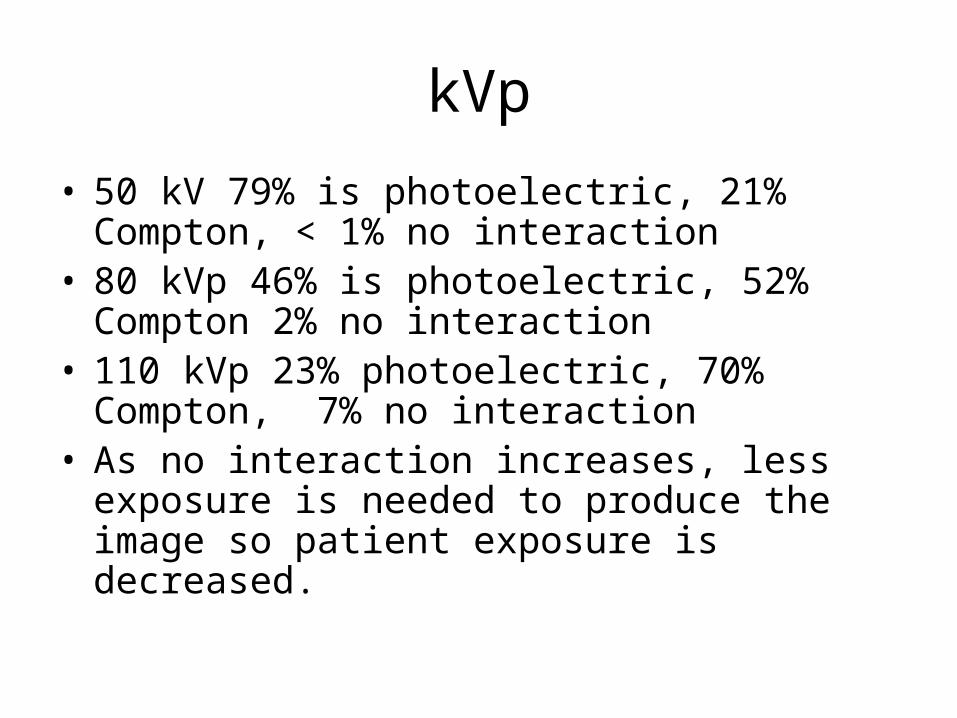
• 50 kV 79% is photoelectric, 21% Compton, < 1% no interaction
• 80 kVp 46% is photoelectric, 52% Compton 2% no interaction
• 110 kVp 23% photoelectric, 70% Compton, 7% no interaction
• As no interaction increases, less exposure is needed to produce the image so patient exposure is decreased.
mA
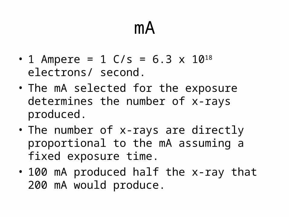
• 1 Ampere = 1 C/s = 6.3 x 10¹⁸ electrons/ second.• The mA selected for the exposure determines
the number of x-rays produced.• The number of x-rays are directly proportional to
the mA assuming a fixed exposure time.• 100 mA produced half the x-ray that 200 mA
would produce.

mA
• Patient dose is also directly proportional to the mA with a fixed exposure time.
• A change in mA does not affect kinetic energy of the electrons therefore only the quantity is changed.

mA
• Many x-ray machines are identified by the maximum mA or mAs available.
• A MP 500 has a maximum mAs of 500 mAs.
• A Universal 325 has a maximum mA of 300 and maximum kVp of 125
mA
• More expensive three phase machines will have a higher maximum mA.
• A General Electric MST 1050 would have 1000 mA and 150 kVp.

Exposure Time
• The exposure time is generally always kept as short as possible.
• This is not to reduce patient exposure but to minimize motion blur resulting from patient movement.
• This is a much greater problem with weight bearing radiography.
Exposure Time
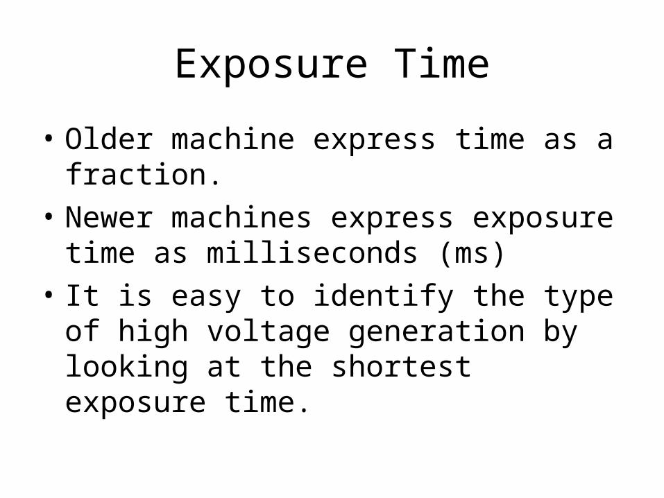
• Older machine express time as a fraction.
• Newer machines express exposure time as milliseconds (ms)
• It is easy to identify the type of high voltage generation by looking at the shortest exposure time.

Exposure Time
• Single phase half wave rectified fasted exposure time is 1/60 second 17 ms.
• Single phase full wave rectified fastest exposure time is 1/120 second or 8 ms
• Three phase and high frequency can provide exposure time down to 1 ms.

mAs
• mA and exposure time is usually combined and used as one factor expressed as mAs.
• mAs controls radiation quantity, optical density and patient dose.
• mAs determine the number of x-rays in the beam and therefore radiation quantity.
• mAs does not influence radiation quality.
mAs
• Any combination of mA and time that will give the same mAs should provide the same optical density on the film. This is referred to as the reciprocity law.
• As noted earlier for screen film radiography, 1 ms exposure and exposure longer than 1 seconds do not follow this rule.
mAs
• On many modern machines, only mAs can be selected. The machine automatically gives the operator the highest mA and shortest exposure time.
• The operator may be able to select mA by what is referred to as Power level.

mAs
• mAs is one way to measure electrostatic charge. It determines the total number of electrons.
• Only the quantity of the photons are affected by changes in the mAs.
• Patient dose is therefore a function of mAs.
mAs
• If we know the mR/mAs, multiply that figure times the mAs. or
• If we know the mR for a given exposure at a given kVp, we can divide the exposure by the mAs to get the mR/ mAs.
• To compute exposure we need to know what the mR/mAs is for the kVp used and the SID.

Distance
• Distance affects the exposure of the image receptor according to the inverse square law.
• Distance affects the intensity of the x-ray beam at the film but has no effect on radiation quality.
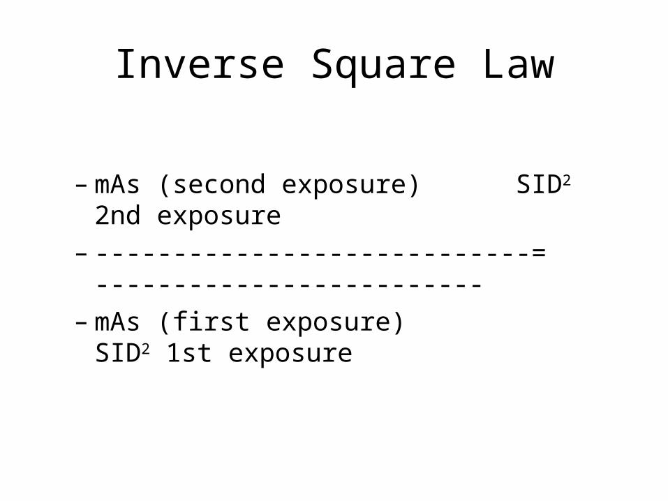
Inverse Square Law
– mAs (second exposure) SID2 2nd exposure
– ----------------------------= -------------------------– mAs (first exposure) SID2 1st exposure

Distance
• The most common source to image distances are 40” (100 cm) and 72”(182 cm)
• Since SID does not impact the quality of the beam, adjustments to the technical factors are made with the mAs.
• To go from 40” to 72” increase the mAs 3.5 time.
Distance
• Increasing the distance will impact the geometric properties of the beam.
• Increased SID reduces magnification distortion and focal spot blur.
• With the need to increase the mAs 3.5 times for the 72” SID, tube loading becomes a concern.
Distance
• 72” SID is used for Chest radiography and the lateral cervical spine to reduce magnification.
• 72” SID used for the full spine to get a 36” beam.

Imaging System Characteristics
• Operator has limited control.
• The following will impact the technical factors based upon the type of machine.– Focal Spot Size– Filtration– High-voltage Generation
Focal Spot Size
• Most machines limited to two focal spot sizes.
• Common office focal spots are 1.0 mm for the small and 2.0 mm for large.
• Highly detailed radiography such as mammography use micro-focus tubes with 0.1 mm and 0.3 mm focal spot sizes.
Focal Spot Size
• The focal spot size limits the tube’s capacity to produce x-rays. The electrons and resulting heat are placed on a smaller portion of the x-ray tube.
• The mA is therefore limited for the small focal spot. This results in longer exposure times with greater chance of patient movement.
Focal Spot Size
• For single phase machines, the small focal spot use is limited to extremities and the cervical spine.
• With high frequency, most views can be done on the small focal spot except for larger patient and ones that cannot hold still.
• My limit is exposure times less than 1/2 s.
Focal Spot Size
• If the mA is properly calibrated, the focal spot will have no impact on the quantity or quality of the beam.
Filtration
• All x-ray beams are affected by the filtration of the tube. The tube housing provides about 0.5 mm of filtration.
• Additional filtration is added in the collimator to meet the 2.5 mm of aluminum minimum filtration required by law.
• 2.5 mm is required for 70 kVp.

Filtration
• 3.0 mm is required for at 100 kVp.
• 3.2 mm is required for operations at 120 kVp.
• Most machines now are capable of over 100 kVp operation.
• We have no control on these filters.
Filtration
• Chiropractic radiography is a leader in the use of compensating filters. We have total control over compensating filtration.
• In areas of the body with high subject contrast or wide differences in density, compensating films improve image quality and reduce patient exposure.

High-voltage Generation
• You will determine the type of high-voltage generation when you purchase your x-ray machine.
• The type of generator will determine the efficiency of the generator or the amount of ripple in the wave form.
• Single phase has 100% ripple.
Three Phase Generation
• Three phase has a 14% so it is significant improvement in efficiency increasing both quality and quantity of the beam.
• More x-rays per mAs with higher energy.
• Cost to provide 3 phase power is very high so not practical in office.

High Frequency Generation
• Virtually no ripple ( less than 1%.)
• Inexpensive and can use normal incoming power.
• Provides significant reduction is mAs or kVp compared to single phase. Reduction of mAs by 50% compared to single phase techniques.

Chapter 19 Radiographic Quality
• Radiographic Quality refers to the fidelity with which the anatomic structures being examined are images on the film.
• Three main factors:– Film Factors– Geometric Factors– Subject Factors
Radiographic Quality
• Characteristic of radiographic quality:– Spatial Resolution (Recorded Detail)– Contrast Resolution (Visibility of Detail)– Noise (Visibility of Detail)– Artifacts
Spatial Resolution
• Spatial Resolution is the ability to image small structures that have high subject contrast such as bone-soft tissue interface.
• When all of the factors are correct, conventional radiography has excellent spatial resolution.

Contrast Resolution
• Contrast resolution is the ability to distinguish structures with similar subject contrast such as liver-spleen, fat-muscle.
• Computed tomography and MRI have excellent contrast resolution. Convention radiology is fair to poor.

Noise
• Noise is an undesirable fluctuation in optical density of the image. Two major types:– Film Graininess- no control over– Quantum Mottle- some control over

Film Graininess
• Film graininess refers to the distribution in size and space of the silver halide grains in the film emulsion.
• Similar to photographic film. 400 ASA film is more graininess than 100 ASA film.
• Similar to structure mottle that refers to the size and shape of the phosphors in the intensifying screens.
Quantum Mottle
• Quantum mottle refers to the random nature of how the x-rays interact with the image receptor.
• It is the primary form of radiographic noise.
• The use of high mAs and low kVp reduced quantum mottle.
Quantum Mottle
• Very fast screens have higher quantum mottle because it takes fewer x-rays to make the image.

Speed
• Resolution and noise are intimately connected with speed.
• While the speed of the images receptor is not apparent on the image, it influences both resolution and noise.
Radiographic Quality Rules
• Fast Image receptors have high noise and low spatial and contrast resolution.
• High spatial and contrast resolution require low noise and slow image receptors.
• Low noise accompanies slow image receptors with high spatial and contrast resolution.
Film Factors of Quality
• Characteristic curve– Density– Contrast– Latitude
• Processing– Time– Temperature
Sensitometry
• Sensitometry is the study of the relationship between the intensity of exposure of the film and the blackness after the film is processed.
• Unexposed film is clear with a blue tint after processing.
• Exposed film is black after processing.
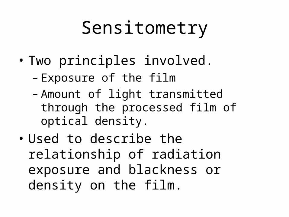
Sensitometry
• Two principles involved.– Exposure of the film– Amount of light transmitted through the
processed film of optical density.
• Used to describe the relationship of radiation exposure and blackness or density on the film.

Characteristic Curve
• This relationship is called the characteristic curve or H & D curve of the film.
• H & D stands for Hurter and Driffield.

Parts of the Characteristic Curve
• Toe and shoulder where large changes in exposure results in small changes in OD.
• Very high and very low variations of exposure make very small changes in density.

Parts of the Characteristic Curve
• The straight line or intermediate area is where very small changes in exposure results in large changes in density.
• This is the important part of the curve in radiography.
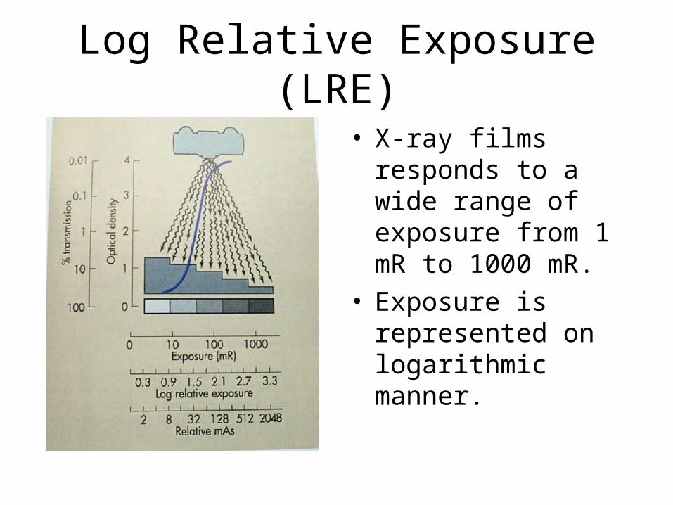
Log Relative Exposure (LRE)
• X-ray films responds to a wide range of exposure from 1 mR to 1000 mR.
• Exposure is represented on logarithmic manner.
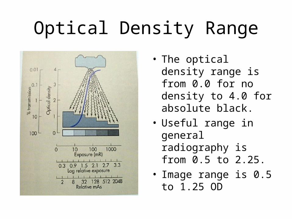
Optical Density Range
• The optical density range is from 0.0 for no density to 4.0 for absolute black.
• Useful range in general radiography is from 0.5 to 2.25.
• Image range is 0.5 to 1.25 OD
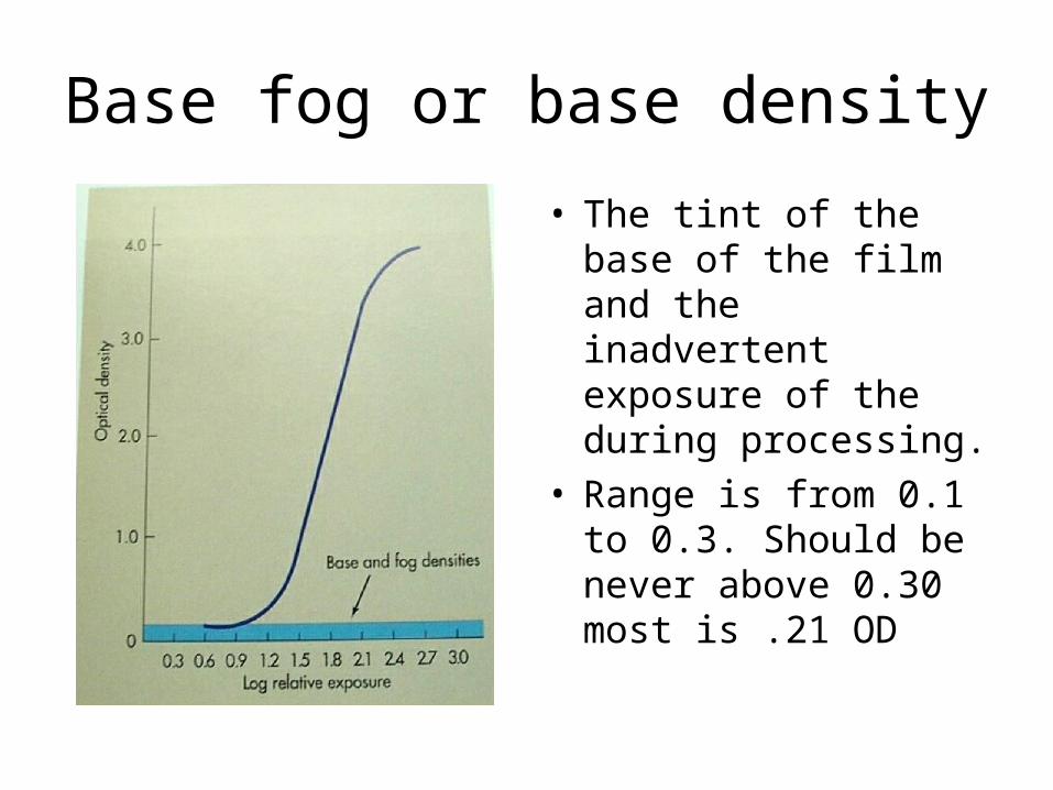
Base fog or base density
• The tint of the base of the film and the inadvertent exposure of the during processing.
• Range is from 0.1 to 0.3. Should be never above 0.30 most is .21 OD
Items that Impact Base Fog
• Film storage
• Film exposure to wrong spectrum of light or light intensity.
• Chemical contamination.
• Improper processing.
• High Base fog levels reduce contrast.

Contrast
• Radiographic Contrast is the combined result of image receptor contrast and subject contrast.
• Image receptor contrast refers to the contrast inherent in the film and influenced by the processing of the film.
Contrast
• Subject contrast is determined by the size, shape and x-ray attenuating characteristics of the subject being examined and the energy (kVp) of the x-ray beam.
Image Receptor Contrast
• Inherent to the film and screen combination but is influenced by:– Range of Optical Density– Film Processing Technique
• Film type is determined by the type of intensifying screens used but many dealers sell off brands of film.
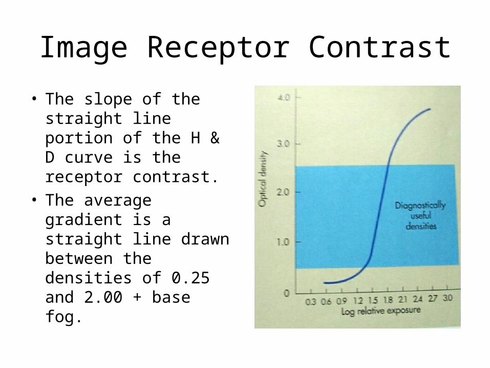
Image Receptor Contrast
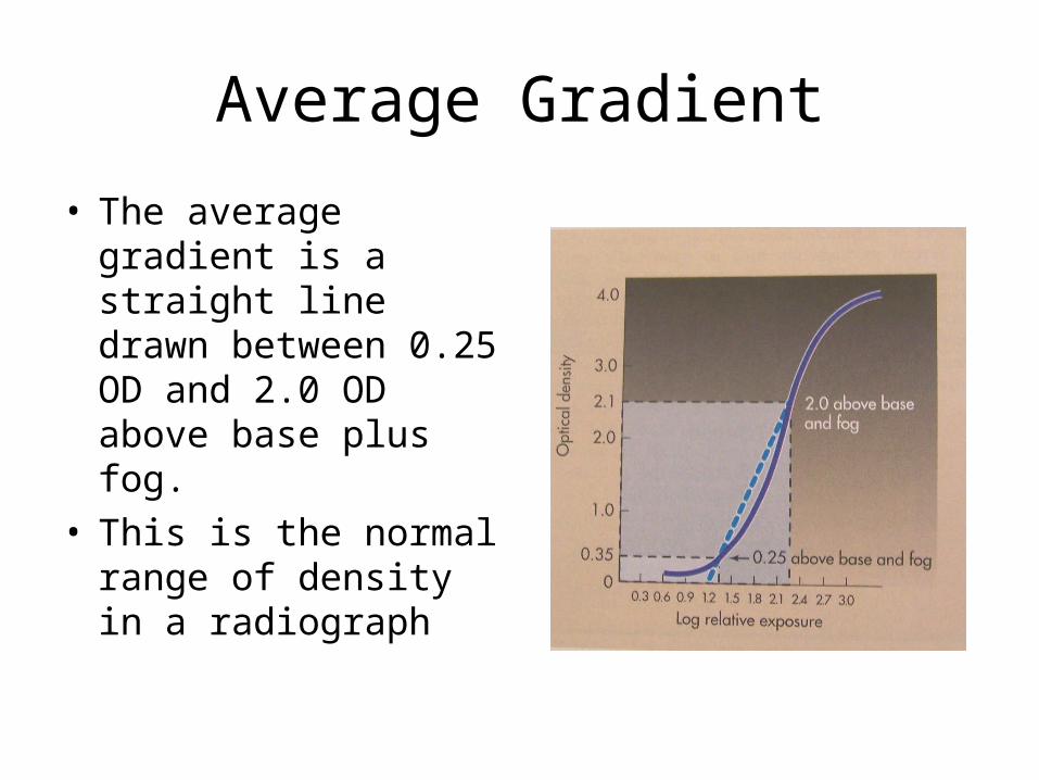
• The slope of the straight line portion of the H & D curve is the receptor contrast.
• The average gradient is a straight line drawn between the densities of 0.25 and 2.00 + base fog.
Average Gradient
• The average gradient is a straight line drawn between 0.25 OD and 2.0 OD above base plus fog.
• This is the normal range of density in a radiograph
Speed
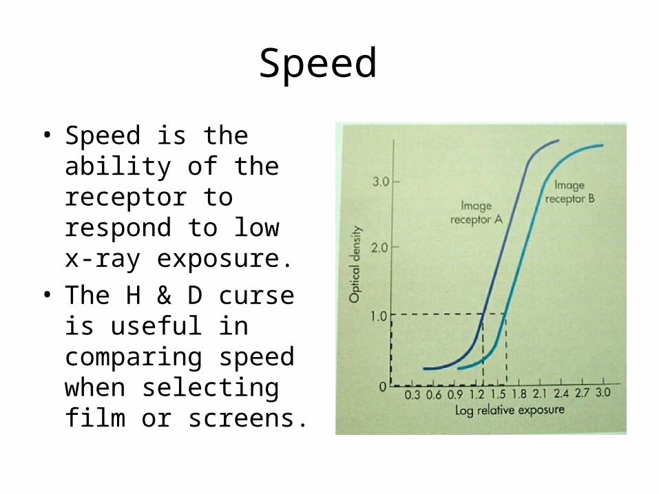
• Speed is the ability of the receptor to respond to low x-ray exposure.
• The H & D curse is useful in comparing speed when selecting film or screens.
Speed
• A relative number of 100 given to Par Speed Calcium Tungstate Screens.
• High Speed Calcium Tungstate has a speed of 200. Half of the exposure is needed to produce the same image.
• Rare earth screen film combinations range is speed from 80 to 1600.
Speed
• By knowing the Speed, sometimes referred to as the Relative Speed Value, it is easy to convert the technical factors for one speed to another speed.

LATITUDE
• Latitude can be observed on the H & D curve.
• Latitude refers to the range of exposure that will produce a diagnostic range OD.

Latitude
• Latitude and Contrast are inversely proportional.
• Wide latitude has a wide gray scale or low contrast. (B)
• Narrow latitude has a short scale or high contrast. (A)
Latitude
• Latitude is designed into some screen and film combinations. With wide latitude, the error factor in technique is wider.
• Latitude can also be impacted by the technical factors.
Film Processing
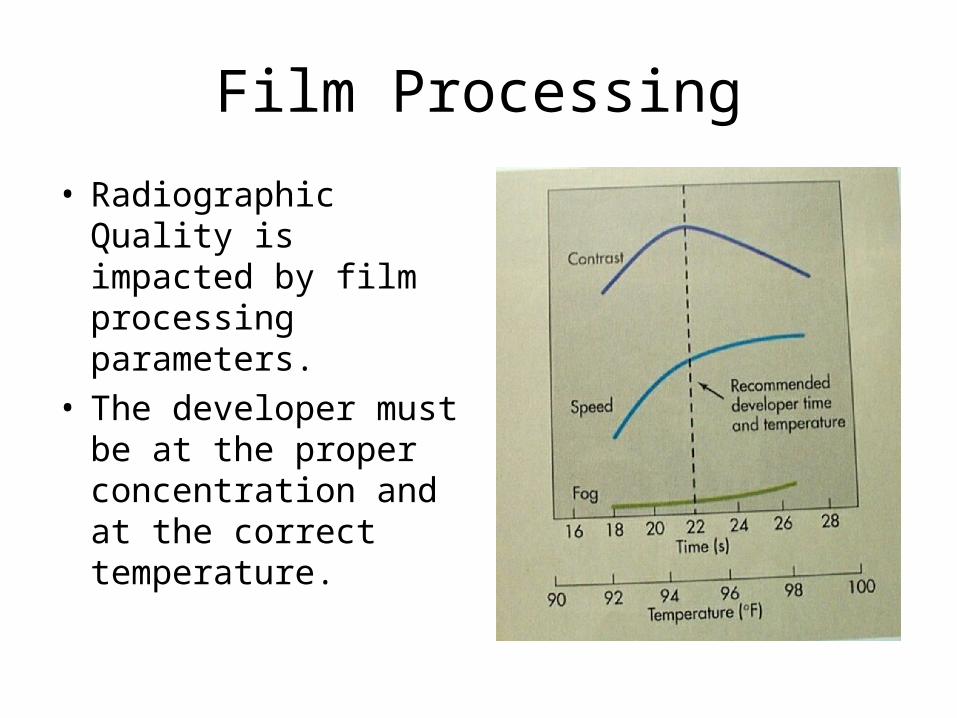
• Radiographic Quality is impacted by film processing parameters.
• The developer must be at the proper concentration and at the correct temperature.
Film Processing
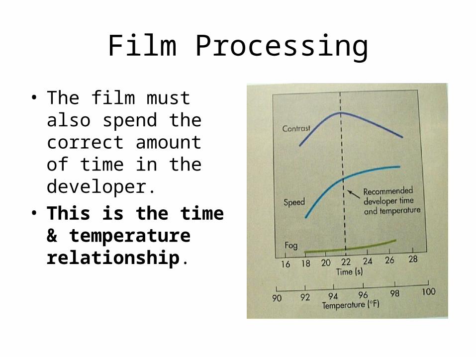
• The film must also spend the correct amount of time in the developer.
• This is the time & temperature relationship.
Processing
• Speed and base fog increase with the temperature.
• Contrast will increase to a point and then drop with the base fog increase.
• Manufactures set processing parameters to optimize speed, contrast and low base fog.
Processing
• In 9th Quarter we will discuss processor quality control in detail.

End of Lecture
Return to Lecture Index
Return to Physics Homepage