chapter 16 deep foundations - university of … manual/south... · chapter 16 deep foundations ....
TRANSCRIPT

Chapter 16
DEEP FOUNDATIONS
Final
SCDOT GEOTECHNICAL DESIGN MANUAL
June 2010

SCDOT Geotechnical Design Manual Deep Foundations
Table of Contents Section Page
16.1 Introduction.......................................................................................................16-1 16.2 Design Considerations .....................................................................................16-3
16.2.1 Axial Load.............................................................................................16-3 16.2.2 Lateral Load..........................................................................................16-4 16.2.3 Settlement ............................................................................................16-4 16.2.4 Scour ....................................................................................................16-5 16.2.5 Downdrag .............................................................................................16-5
16.3 Driven Piles ......................................................................................................16-5 16.3.1 Axial Compressive Capacity.................................................................16-7 16.3.2 Axial Uplift Capacity............................................................................16-10 16.3.3 Group Effects......................................................................................16-10 16.3.4 Settlement ..........................................................................................16-10 16.3.5 Pile Drivability .....................................................................................16-12
16.4 Drilled shafts...................................................................................................16-14 16.4.1 Axial Compressive Capacity...............................................................16-14 16.4.2 Uplift Capacity ....................................................................................16-17 16.4.3 Group Effects......................................................................................16-18 16.4.4 Settlement ..........................................................................................16-18
16.5 Drilled piles.....................................................................................................16-20 16.6 Continuous flight auger piles ..........................................................................16-20 16.7 Micropiles .......................................................................................................16-20 16.8 Lateral Capacity .............................................................................................16-20 16.9 Downdrag .......................................................................................................16-21 16.10 Foundation Length .........................................................................................16-23 16.11 References .....................................................................................................16-24
Jnue 2010 16-i
SCDOT Geotechnical Design Manual Deep Foundations
List of Tables Table Page
Table 16-1, Deep Foundation Limit States...................................................................16-3 Table 16-2, Typical Pile Types and Sizes ....................................................................16-6 Table 16-3, Drivability Analysis ..................................................................................16-13 Table 16-4, k Factor ...................................................................................................16-19 Table 16-5, Governing Conditions .............................................................................16-23 Table 16-6, Pile Bearing.............................................................................................16-23 Table 16-7, Drilled Shaft Bearing ...............................................................................16-24
16-ii June 2010

SCDOT Geotechnical Design Manual Deep Foundations
Jnue 2010 16-iii
List of Figures Figure Page
Figure 16-1, Reasons for Deep Foundations ...............................................................16-2 Figure 16-2, Typical Wave Equation Model ...............................................................16-12


Jnue 2010 16-1
CHAPTER 16
DEEP FOUNDATIONS
16.1 INTRODUCTION
This Chapter provides general guidance in the design and analysis of deep foundations used to support highway structures. Deep foundations are used in lieu of shallow foundations on the majority of SCDOT projects. Deep foundations consist of driven piles, drilled shafts or piers, drilled piles, auger cast-in-place (continuous flight auger, CFA) piles and micro-piles. Each foundation type has specific advantages and disadvantages that will be discussed in subsequent Sections. The design of deep foundations is comprised of 2 components, the bearing (resistance to shear) capacity and settlement (performance limits); however, in the design of deep foundations bearing typically governs.
According to NAVFAC DM-7.2 deep foundations are defined as developing bearing at depths (Df) greater than 5 times the size (diameter) (Bf) of the foundation (i.e. Df ≥ 5Bf). As indicated previously, bearing typically governs the design of deep foundations not settlement. The bearing of deep foundations is based on either the end bearing (Qt) or skin friction (Sf) along the shaft of the foundation acting independently of the other component or a combination of the two components acting together. Deep foundations need to be considered for several reasons:
When the upper soil strata are too weak or compressible to support the required vertical loads (a), (b), (c) (letters refer to Figure 16-1);
When shallow foundations cannot adequately support inclined, lateral, or uplift loads, and overturning moments (d), (e), (f);
When scour around foundations could cause loss of bearing capacity at shallow depths (g);
When soils around foundations are subjected to liquefaction during seismic events (h);
When fender systems are required to protect bridge piers from vessel impact (i);
When future excavations are planned which would require underpinning of shallow foundations (j), and;
When expansive or collapsible soils are present, which could cause undesirable seasonal movements of the foundations (k).

SCDOT Geotechnical Design Manual Deep Foundations
16-2 June 2010
Note: Illustrations (e) and (i) above shows battered piles, please note that SCODT prefers vertical piles.
Figure 16-1, Reasons for Deep Foundations (Hannigan et al, 2006)
All deep foundation designs will be governed by the basic LRFD equation.

strniii RRRRQQ Equation 16-1
Where,
Q = Factored Load Qi = Force Effect i = Load modifier i = Load factor Rr = Factored Resistance (i.e. allowable capacity) Rn = Nominal Resistance (i.e. ultimate capacity) Rt = Nominal Tip Resistance RS = Nominal Skin Friction Resistance
= Resistance Factor Selection of the resistance factor () will be discussed in greater detail in the following Sections. Typically, the resistance factor is based on the method of construction control for piles and on the type of material and where (i.e. end or side) the capacity is developed. SCDOT does not use design method specific resistance factors (see Chapter 9). The factored load is provided by the bridge (structural) engineer. 16.2 DESIGN CONSIDERATIONS
The design of deep foundations supporting bridge piers, abutments, or walls should consider all limit state loading conditions applicable to the structure being designed. A discussion of the load combination limit states that are used in deep foundation design is discussed in Chapter 8 and the Deep Foundation performance limit with corresponding limit state is reproduced below in Table 16-1. Most substructure designs will require the evaluation of foundation and structure performance at the Strength I and Service I limit states. These limit states are generally similar to evaluations of ultimate capacity and deformation behavior in ASD, respectively.
Table 16-1, Deep Foundation Limit States
Limit States
Performance Limit Strength Service
Extreme Event
Axial Compression Load √ √ Axial Uplift Load √ √
Structural Capacity1 √ √ Lateral Displacements √ √
Settlement √ √ 1Determined by Bridge (Structural) Engineer
16.2.1 Axial Load Axial loadings should include both compressive and uplift forces in evaluation of deep foundations. Forces generated from the Strength limit state and Extreme Event limit state are used to determine nominal axial pile resistances from the axial design process. The Strength limit state is a design boundary condition considered to ensure that strength and stability are provided to resist specified load combinations, and avoid the total or partial collapse of the
Jnue 2010 16-3

SCDOT Geotechnical Design Manual Deep Foundations
16-4 June 2010
structure. The Extreme Event limit states are design boundary conditions considered to represent an excessive or improbable loading combination. Such conditions may include ship impacts, vehicle impact, and seismic events. Because the probability of this event occurring during the life of the structure is relatively small, a smaller safety margin is appropriate when evaluating this limit state. The static capacity of a pile/shaft can be defined as the sum of soil/rock resistances along the pile/shaft surface and at the pile/shaft toe available to support the imposed loads on the pile. A static analysis is performed to determine the nominal bearing resistance (Rn) of an individual pile/shaft and of a pile/shaft group as well as the deformation response of a pile and/or group to the applied loads. The nominal bearing resistance (Rn) of an individual pile and of a pile group is the smaller of:
(1) the capacity of surrounding soil/rock medium to support the loads transferred from the pile/shaft or,
(2) the structural capacity of the pile/shaft.
The static pile/shaft capacity from the sum of the soil/rock resistances along the pile/shaft surface and at the pile/shaft toe can be estimated from geotechnical engineering analysis using:
(1) Laboratory determined shear strength parameters of the soil and rock surrounding the pile;
(2) Standard Penetration Test (SPT) data;
(3) In-Situ Test data (i.e. CPT); or
(4) Full scale load test data.
16.2.2 Lateral Load Lateral loadings applied in foundation design should consider foundation members placed through embankments, locations on, near or within a slope, loss of support due to erosion or scour, and the bearing strata significantly inclined. Forces generated from the Service limit state and Extreme Event limit state are used to determine the horizontal and vertical movements of the foundation system. The Service limit state is a design boundary condition for structure performance under intended service loads, and accounts for some acceptable measure of structure movement throughout its performance life. The Extreme Event limit states are design boundary conditions considered to represent an excessive or improbable loading combination. Such conditions may include ship impacts, vehicle impact, and seismic events. Because the probability of this event occurring during the life of the structure is relatively small, a smaller safety margin is appropriate when evaluating this limit state. 16.2.3 Settlement The amount of settlement is normally limited to the amount required to develop the capacity of the deep foundation element. Settlements are determined for the Service limit state. The settlement is not normally determined on individual driven piles, micro-piles or CFAs, while the
Jnue 2010 16-5
settlement on individual shafts is normally determined. For deep foundations, the settlement of group is normally determined. In addition, the elastic shortening of the deep foundation elements due to the load should be included in the overall settlement. The inclusion of elastic shortening is required, since the performance of the structure will be affected by this movement. Static analysis calculations of the deformation response to lateral loads and of pile/shaft groups’ settlement are compared to the performance criteria established for the structure.
16.2.4 Scour The design of deep foundations shall consider the effects of scour on the capacity and length requirements of the foundation. The nominal capacity of deep foundations shall be determined for the soils beneath the scourable soils. The depth of scour shall be determined by the Hydraulic Engineering Group. The capacity of the scourable soils shall be added to the nominal capacity of driven piles when developing driving criteria, but no such increase in capacity is required for the drilled shafts, CFAs and micro-piles because they are not driven. The following Sections will provide additional details for handling scour for each foundation type. 16.2.5 Downdrag Downdrag on deep foundations is caused by two distinct phenomena, settlement of subgrade soils and seismically induced liquefaction. Settlement is normally anticipated to occur at the end bent of bridges where the bridge meets the road embankment. Downdrag induced settlements are applied to the Strength limit state of the deep foundation. Downdrag loads will be discussed in the following Sections, while the settlement of the embankments is discussed in Chapter 17. The other phenomenon that can cause downdrag is seismically induced liquefaction. This downdrag load is applied to the Extreme Event limit state and will be discussed in the following Sections in greater detail. The amount of seismically induced liquefaction settlement is determined using the procedures outlined in Chapter 13. 16.3 DRIVEN PILES
Driven piles typically used by SCDOT include prestressed concrete, steel H-piles, steel pipe piles and combination piles consisting of concrete and steel H-pile sections. In addition, SCDOT has used timber piles in the past; however, timber piles are no longer allowed for the support of bridge structures. Concrete cylinder piles are currently being evaluated for inclusion in the pile types used by SCDOT. The use of concrete cylinder piles shall be approved in writing by SCDOT prior to commencing design. Piling is further categorized as either displacement or non-displacement. Displacement piles increase lateral ground stresses, densify cohesionless soils, can weaken cohesive soils (temporarily), have large set up times for fine-grained soils, and primarily get their capacity from skin friction. Typically prestressed concrete and closed-ended steel pipe piles are considered displacement piles. Non-displacement piles usually cause minimal disturbance to surrounding soil and primarily get their capacity from end bearing. Steel H-piles and opened steel pipe piles are considered non-displacement piles. According to the Bridge Design Manual (BDM) the minimum length of driven piling is 10 feet. The BDM provides typical sizes for driven piles. Table 16-2 provides a summary of these pile types and sizes.

SCDOT Geotechnical Design Manual Deep Foundations
16-6 June 2010
Table 16-2, Typical Pile Types and Sizes
Pile Type Size
Steel H-piles
HP 12x53 HP 14x73 HP14x89
HP 14x1171
Steel Pipe Piles
16-inch2
18-inch2
20-inch2
24-inch2
Prestressed Concrete Piles3
18-inch 20-inch 24-inch 30-inch4 36-inch4
Composite piles 18-inch with W 8x58 stinger
20-inch with HP 10x57 stinger24-inch with HP 12x53 stinger
1used where penetration is minimal and nominal capacity is large 2wall thickness is ½ inch for all pipe pile sizes 3prestressed concrete piles are square in section 4these sizes are only allowed with the written approval of SCDOT
As required by AASHTO LRFD Bridge Design Specifications latest edition, driven pile analyses and design should address the following:
Nominal axial resistance, pile type, size of pile group, and how the nominal axial pile resistance will be determined in the field;
Pile group interaction;
Pile penetration required to meet nominal axial resistance and other design requirements;
Minimum pile penetration necessary to satisfy the requirements caused by uplift, scour, downdrag, settlement, liquefaction, lateral loads, and seismic conditions;
Foundation deflection should meet the established movement and associated structure performance criteria;
Pile foundation nominal structural resistance;
Verification of pile driveability to confirm acceptable driving stresses and blow counts can be achieved, and;
Long-term durability of the pile in service (i.e. corrosion and deterioration).
A thorough reference on pile foundations is presented in the FHWA publication Design and Construction of Driven Pile Foundations – Volume I and II (Hannigan et al, 2006).
16.3.1 Axial Compressive Capacity There are numerous static analysis methods available for calculating the bearing capacity of a single pile. The axial compressive capacity for driven piles shall follow the procedures provide in the AASHTO LRFD Bridge Design Specifications (latest edition), Article 10.7 - Driven Piles. The methods found in the AASHTO LRFD Bridge Design Specifications are used to satisfy the Strength and Extreme Event limit states.
The basic LRFD equation presented previously and in Chapter 8 is expanded on the resistance side of the equation to account for the factored resistance of piles (Rr), and may be taken as:
strn RRRRQ Equation 16-2
ttt AqR * Equation 16-3
sss AqR * Equation 16-4
Where,
Q = Factored Load (demand) Rr = Factored Resistance (i.e. allowable capacity) Rn = Nominal Resistance (i.e. ultimate capacity) Rt = Nominal Tip Resistance qt = unit tip resistance of pile (force/area) At = area of pile tip (area) RS = Nominal Skin Friction Resistance qs = unit side resistance of pile (force/area) As = surface area of pile side (area)
= Resistance Factor (see Chapter 9)
The nominal capacity of driven pile shall include the effects of scour. The nominal capacity shall be developed beneath the scour elevation or depth; however, the capacity developed in the scourable soils shall be determined and added to the nominal capacity to obtain the required ultimate bearing for use during pile installation.
The axial compressive design methodologies can be separated based on either total or effective stress methods or whether the soils are cohesionless or cohesive in nature. As indicated in the above equations the total axial compressive capacity of a deep foundation is based on the combination of unit side resistance and unit tip resistance values. Another factor that affects the axial compressive capacity of driven piles is the type of pile being installed (i.e. non-displacement vs. displacement). The followings methods shall be used to determine the capacity of driven piles:
(1) Nordlund Method: This method is an effective stress method and is used for sands and non-plastic silts (cohesionless soils). Further this method is based on field observations and considers the pile shape, and its soil displacement properties in calculating the shaft resistance. The unit shaft resistance is a function of: friction angle of the soil, the friction
Jnue 2010 16-7
SCDOT Geotechnical Design Manual Deep Foundations
16-8 June 2010
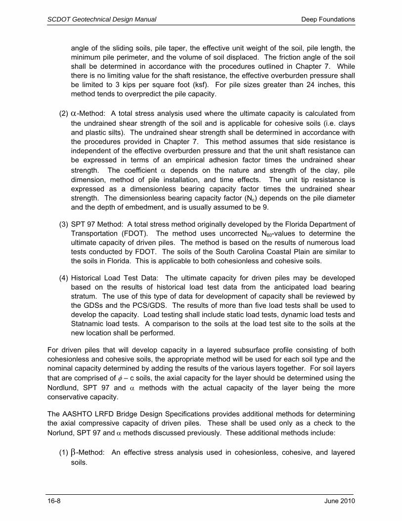
angle of the sliding soils, pile taper, the effective unit weight of the soil, pile length, the minimum pile perimeter, and the volume of soil displaced. The friction angle of the soil shall be determined in accordance with the procedures outlined in Chapter 7. While there is no limiting value for the shaft resistance, the effective overburden pressure shall be limited to 3 kips per square foot (ksf). For pile sizes greater than 24 inches, this method tends to overpredict the pile capacity.
(2) -Method: A total stress analysis used where the ultimate capacity is calculated from the undrained shear strength of the soil and is applicable for cohesive soils (i.e. clays and plastic silts). The undrained shear strength shall be determined in accordance with the procedures provided in Chapter 7. This method assumes that side resistance is independent of the effective overburden pressure and that the unit shaft resistance can be expressed in terms of an empirical adhesion factor times the undrained shear
strength. The coefficient depends on the nature and strength of the clay, pile dimension, method of pile installation, and time effects. The unit tip resistance is expressed as a dimensionless bearing capacity factor times the undrained shear strength. The dimensionless bearing capacity factor (Nc) depends on the pile diameter and the depth of embedment, and is usually assumed to be 9.
(3) SPT 97 Method: A total stress method originally developed by the Florida Department of Transportation (FDOT). The method uses uncorrected N60-values to determine the ultimate capacity of driven piles. The method is based on the results of numerous load tests conducted by FDOT. The soils of the South Carolina Coastal Plain are similar to the soils in Florida. This is applicable to both cohesionless and cohesive soils.
(4) Historical Load Test Data: The ultimate capacity for driven piles may be developed based on the results of historical load test data from the anticipated load bearing stratum. The use of this type of data for development of capacity shall be reviewed by the GDSs and the PCS/GDS. The results of more than five load tests shall be used to develop the capacity. Load testing shall include static load tests, dynamic load tests and Statnamic load tests. A comparison to the soils at the load test site to the soils at the new location shall be performed.
For driven piles that will develop capacity in a layered subsurface profile consisting of both cohesionless and cohesive soils, the appropriate method will be used for each soil type and the nominal capacity determined by adding the results of the various layers together. For soil layers that are comprised of – c soils, the axial capacity for the layer should be determined using the Nordlund, SPT 97 and methods with the actual capacity of the layer being the more conservative capacity.
The AASHTO LRFD Bridge Design Specifications provides additional methods for determining the axial compressive capacity of driven piles. These shall be used only as a check to the Norlund, SPT 97 and methods discussed previously. These additional methods include:
(1) -Method: An effective stress analysis used in cohesionless, cohesive, and layered soils.
Jnue 2010 16-9
(2) -Method: An effective stress method that relates undrained shear strength and effective overburden to the shaft resistance.
(3) Meyerhof SPT data Method: This method was derived by empirical correlations between Standard Penetration Test (SPT) results and static pile load tests for cohesionless soils.
(4) Nottingham and Schmertmann CPT Methods: The method uses Cone Penetrometer Test data relating pile shaft resistance to CPT sleeve friction.
In addition, Hannigan et al (2006) provides additional procedures for determining the axial compressive capacity of driven piles.
(1) Brown Method: An empirical method using SPT data for cohesionless materials.
(2) Elsami and Fellenius Method: A CPT based method that correlates the effective tip resistance to the unit shaft resistance.
(3) Laboratoire des Ponts et Chaussess (LPC) Method: A CPT based method that correlates the tip resistance, soil type, pile type and installation method to the unit shaft resistance.
As with the other methods listed in the AASHTO LRFD Bridge Design Specifications, these methods shall only be used to check the capacities determined by the Norlund, SPT 97 and methods.
For driven piles bearing in rock with a RQD greater than 10 percent (see Chapter 6), the nominal capacity of the pile is typically limited by the structural capacity of the foundation element itself. This is especially true with prestressed concrete piles driven into rock, and why prestressed concrete piles typically have pile points when driven to bearing in rock. In many cases steel piles are fitted with “reinforced tips” to avoid damage to the foundation element.
There are numerous computer software packages available for performing the axial compressive capacity of driven pile foundations. The preferred software packages are DRIVEN as provided by the FHWA (www.fhwa.dot.gov/engineering/geotech/software/softwaredetail.cfm#driven) or SPT 97 as developed by the University of Florida for FDOT. The latest version of SPT 97 is contained within FB-Deep as developed by the University of Florida, Bridge Software Institute (http://bsi-web.ce.ufl.edu/products/). DRIVEN uses the Norlund and methods for determining axial capacity for cohesionless and cohesive soils, respectively. FB-Deep can be applied to both cohesionless and cohesive soils. Other computer software packages may be used to determine axial compressive capacity of driven piles; however, prior to being used, the designer must submit copies of the output, the method used for design, a set of hand calculations performed using the procedure and evidence of applicability and acceptability using load testing information. This information shall be submitted to the PCS/GDS for technical review prior to being approved. It is incumbent upon the engineer, that prior to using any software, that the methodologies used by the software are fully understood.

SCDOT Geotechnical Design Manual Deep Foundations
16-10 June 2010
16.3.2 Axial Uplift Capacity The axial uplift capacity should be evaluated when tensile forces may be present. The side resistance of the driven pile shall be determined using either the Norlund or methods. All capacity losses due to scour shall not be included in the determination of the axial uplift capacity. In addition, static settlement induced downdrag shall also not be included, since it is anticipated that at some point in time settlement will cease. The factored uplift resistance (Rr) may be evaluated by:
suprn RRRQ Equation 16-5
Where,
Q = Factored Load (demand) Rr = Factored Resistance (i.e. allowable capacity) Rn = Nominal Resistance (i.e. ultimate capacity) RS = Nominal Skin Friction Resistance
and up = Uplift Resistance Factors (see Chapter 9)
16.3.3 Group Effects The analysis procedures discussed in the preceding paragraphs are for single driven piles. For most structures, driven piles are installed in groups. Typically SCDOT uses trestle bents (i.e. a single row of piles); these types of bents shall be considered to be groups for the purpose of determining group efficiency. The nominal axial (compressive or tensile) resistance of a pile group is the lesser of: The sum of individual nominal pile resistances, or The nominal resistance of the pile group considered as a block.
The minimum center-to-center spacing in a trestle bent is 2-1/2 times the nominal pile size; therefore, the group efficiency shall be taken as 1.0. For pile groups having more than two or more rows of piles, the group efficiency shall be determined following the procedures outlined in Article 10.7 of the AASHTO LRFD Bridge Design Specifications. The spacing between piles shall not be less than a center-to-center spacing of 2-1/2 times the nominal pile size in either the longitudinal or transverse directions. The procedures for determining the dimensions of the block are presented in the following section. 16.3.4 Settlement Typically, the settlement of deep foundations is comprised of immediate and primary consolidation settlement and elastic compression (shortening). Secondary compression is not normally considered as part of the settlement of deep foundation. In many cases primary consolidation settlement is not a concern, since most deep foundations are founded in cohesionless soils, overconsolidated (OCR ≥ 4) soils, or rock. Elastic compression is included since the deep foundation will elastically deform when a load is applied. Pile groups are used in determining the amount of settlement instead of single piles, since very rarely are single piles used to support a structure. The total settlement is defined by the following equation.

EscitV SSSS Equation 16-6
Where,
St = ΔV = Total Settlement Si = Immediate Settlement Sc = Primary Consolidation Settlement Ss = Secondary Compression Settlement
ΔE = Elastic Compression
Elastic compression is the compression (deflection or shortening) of a single pile caused by the application of load at the top of the pile. The elastic compression of combination piles is complex or difficult to determine. Therefore, engineering judgment should be used in determining if the concrete or steel portion of the composite pile contributes more to the settlement of the pile group or not. Elastic compression should be determined using the following equation.
AE
LQaE Equation 16-7
Where, Qa = Applied load L = Pile length (embedment) A = Cross sectional area of pile E = Elastic modulus of pile material For piles founded in cohesionless soils and in overconsolidated (OCR ≥ 4) cohesive soils, the settlement shall be determined using elastic theory as presented in Chapter 17. An equivalent foundation is used to determine the dimensions required. The width of the foundation (Bf) is either the pile diameter or face dimension for pile bents or the center to center of the outside piles along the shortest side of a pile footing (group). The length (Lf) is measured from the center to center of the outside piles along the length of the pile bent or pile footing. The depth of the equivalent foundation shall be two-thirds of the pile embedment depth. The applied bearing pressure (qo) shall be taken as the sum of the pile service loads divided by the area of the equivalent footing. For each subsequent layer, the equivalent foundation is enlarged one horizontal to two vertical (1H:2V) portion until the settlement for all subsequent layers is determined. The settlements for pile foundations placed in NC to slightly OC (1 < OCR <4) plastic cohesive soils shall be determined using consolidation theory as presented in Chapter 17. Similar to the elastic settlement determination an equivalent foundation shall be placed two-thirds of the pile embedment depth and the applied bearing pressures and changes in stress determined according. The applied bearing pressure (qo) shall be taken as the sum of the pile service loads divided by the area of the equivalent footing. For each subsequent layer, the equivalent foundation is enlarged one horizontal to two vertical (1H:2V) portion until the settlement for all subsequent layers is determined.
Jnue 2010 16-11

SCDOT Geotechnical Design Manual Deep Foundations
16-12 June 2010
16.3.5 Pile Drivability Pile drivability refers to the ability of a pile to be driven to a desired penetration depth and/or capacity. Pile drivability must be performed as part of the design process. When evaluating drivability, the soil disturbance during installation and the time dependent soil strength changes should be considered.
There are three methods available for predicting and/or checking pile drivability.
Wave Equation Analysis
Dynamic Testing and Analysis
Static Load Tests
Geotechnical Resistance factors for each of these three methods for analysis and level of capacity determination are provided in Chapter 9.
Wave equation analysis is required during design and again during construction. The following graphic illustrates some of the variables involved with the model. The most widely accepted program is GRLWEAP, and is available at http://pile.com/pdi/. It is incumbent upon the engineer, that prior to using any software, that the methodologies used by the software are fully understood.
Figure 16-2, Typical Wave Equation Model
(Hannigan, et al. 2006) Some of the parameters that must be considered are hammer types, cushion material, pile properties and sizes, soil resistance distributions, soil quake and damping parameters. Some of
Jnue 2010 16-13
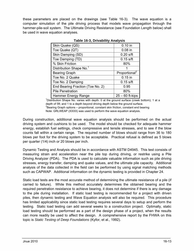
these parameters are placed on the drawings (see Table 16-3). The wave equation is a computer simulation of the pile driving process that models wave propagation through the hammer-pile-soil system. The Ultimate Driving Resistance (see Foundation Length below) shall be used in wave equation analyses.
Table 16-3, Drivability Analysis Skin Quake (QS) 0.10 in Toe Quake (QT) 0.08 in Skin Damping (SD) 0.20 s/ft Toe Damping (TD) 0.15 s/ft % Skin Friction 80% Distribution Shape No.1 1 Bearing Graph Proportional2 Toe No. 2 Quake 0.15 in Toe No. 2 Damping 0.15 s/ft End Bearing Fraction (Toe No. 2) 0.95 Pile Penetration 80% Hammer Energy Range 25 – 60 ft-kips
1Distribution Shape No. varies with depth: 0 at the ground surface (creek bottom); 1 at a depth of 5ft; and 1 to a depth beyond driving depth below the ground surface. 2Bearing Graph options – proportional, constant skin friction, constant end bearing Note: GRLWEAP (XXXX) was used to perform the wave equation analysis.
During construction, additional wave equation analysis should be performed on the actual driving system and cushions to be used. The model should be checked for adequate hammer energy, establish fuel settings, check compressive and tensile stresses, and to see if the blow counts fall within a certain range. The required number of blows should range from 36 to 180 blows per foot for the driving system to be acceptable. Practical refusal is defined as 5 blows per quarter (1/4) inch or 20 blows per inch.
Dynamic Testing and Analysis should be in accordance with ASTM D4945. This test consists of measuring strain and acceleration near the pile top during driving, or restrike using a Pile Driving Analyzer (PDA). The PDA is used to calculate valuable information such as pile driving stresses, energy transfer, damping and quake values, and the ultimate pile capacity. Additional analysis of the data collected in the field can be performed by using signal matching methods such as CAPWAP. Additional information on the dynamic testing is provided in Chapter 24.
Static load tests are the most accurate method of determining the ultimate resistance of a pile (if carried to failure). While this method accurately determines the obtained bearing and the required penetration resistance to achieve bearing, it does not determine if there is any damage to the pile during installation. If static load testing is recommended for a project with driven piles, then dynamic testing and Wave Equation analysis will also be required. This procedure has limited applicability since static load testing requires several days to setup and perform the testing. Static load testing can add several weeks to a construction project. Optimally, static load testing should be performed as a part of the design phase of a project, when the results can more readily be used to affect the design. A comprehensive report by the FHWA on this topic is Static Testing of Deep Foundations (Kyfor, et al., 1992).

SCDOT Geotechnical Design Manual Deep Foundations
16-14 June 2010
16.4 DRILLED SHAFTS
A drilled shaft (also called drilled caisson or caisson) is a deep foundation element that is constructed by excavating a hole with power auger equipment. Reinforcing steel and concrete are then placed within the excavation. In unstable soils, casing or drilling slurry is used to maintain the stability of the hole. Drilling slurry typically consists of natural materials (i.e. bentonite); the use of polymer materials is not allowed. For certain geologic conditions (i.e. sound rock) the use of plain water (potable) as a drilling fluid is allowed; however, permission to use plain water must be obtained from SCDOT. Drilled shafts should be considered when large loads are anticipated (compressive, uplift or lateral) and where the amount of allowable deformation is small. Additionally, drilled shafts should be considered in locations where the losses due to scour are large, seismically induced downdrag loads are large or where the instability of slope cannot be maintained using conventional methods. Further drilled shafts should be considered when there is a limitation on water crossing work.
Drilled shaft sizes (diameters) can typically range from 30 inches (2-1/2 feet) to 144 inches (12 feet). Drilled shaft diameters are normally 6 inches larger than the column above the shaft or 6 inches larger than the rock socket below the shaft. Drilled shaft sizes typically used by SCDOT range from 42 inches (3-1/2 feet) to 84 inches (7 feet) in diameter. According to the BDM drilled shafts are typically used when the span length of a bridge is greater than 50 feet.
As required by AASHTO, the drilled shaft analyses and design should address the following:
Nominal axial resistance of a single shaft and of a group of shafts.
The resistance of the underlying strata to support the load of the shaft group.
The effects of constructing the shaft(s) on adjacent structures.
Minimum shaft penetration necessary to satisfy the requirements caused by uplift, scour, downdrag, settlement, liquefaction, lateral loads, and seismic conditions.
Drilled Shaft nominal structural resistance
Satisfactory behavior under service loads
Long-term durability of the shaft in service (i.e. corrosion and deterioration)
A thorough reference on shaft foundations is presented in the FHWA publication Drilled Shafts: Construction Procedures and Design Methods (O’Neil and Reese, 1999).
16.4.1 Axial Compressive Capacity There are numerous static analysis methods available for calculating the bearing capacity of a single drilled shaft. The axial compressive capacity for drilled shafts shall follow the procedures provide in the AASHTO LRFD Bridge Design Specifications (latest edition), Article 10.8 – Drilled Shafts. The methods found in the AASHTO LRFD Bridge Design Specifications are used to satisfy the Strength and Extreme Event limit states.

The basic LRFD equation presented previously and in Chapter 8 is expanded on the resistance side of the equation to account for the factored resistance of piles (Rr), and may be taken as:
ssttrn RRRRQ Equation 16-8
ttt AqR * Equation 16-9
sss AqR * Equation 16-10
Where,
Q = Factored Load (demand) Rr = Factored Resistance (i.e. allowable capacity) Rn = Nominal Resistance (i.e. ultimate capacity) Rt = Nominal Tip Resistance qt = unit tip resistance of pile (force/area) At = area of pile tip (area) RS = Nominal Skin Friction Resistance qs = unit side resistance of pile (force/area) As = surface area of pile side (area)
, t and s = Resistance Factors (see Chapter 9)
Where construction (permanent) casing is used to maintain the bore hole, the skin friction along the length of the casing shall not be included in the nominal or factored loads. Construction casing should normally be used on all drilled shafts in order to facilitate column construction above the shaft. The nominal resistance should be increased to account for the weight of the column above the top of the drilled shaft, if the provided loads are applied at the bent cap. If however the loads are applied at the top of the drilled shaft then the column weight should not be included.
The axial compressive design methodologies can be separated based on either total or effective stress methods or whether the soils are cohesionless or cohesive in nature. As indicated in the above equations the total axial compressive capacity of a deep foundation is based on the combination of unit side resistance and unit tip resistance values. The factored tip resistance shall be reduced to limit the amount of settlement of the drilled shaft; therefore, satisfying the Service limit state for the drilled shaft. See Chapter 17 for settlement analysis methods.
Provided below are the methods to be used to determine unit side resistances in soils:
-Method: A total stress analysis used where ultimate capacity is calculated from the undrained shear strength of the soil (clay or plastic silt). This approach assumes that side resistance is independent of the effective overburden pressure and that the unit shaft resistance can be expressed in terms of an empirical
adhesion factor times the undrained shear strength. The coefficient is related to the undrained shear strength and is derived from the results of full-scale pile and drilled shaft load tests. The top five feet and bottom one diameter should be ignored in estimating the nominal shaft side resistance. The unit tip resistance is expressed as a dimensionless bearing capacity factor times the undrained shear strength. The dimensionless bearing capacity factor (Nc) depends on the shaft diameter and the depth of embedment, and is usually assumed to be less than 9.
Jnue 2010 16-15

SCDOT Geotechnical Design Manual Deep Foundations
16-16 June 2010
The AASHTO LRFD Bridge Design Specifications provides limitation on the shaft resistance determined using this method; these limitations shall be applied to all projects as required. The exception is if a construction casing is used, the shaft resistance shall be determined from the bottom of the casing to within 1 diameter of the bottom of the shaft.
(2) -Method: An effective stress analysis used in cohesionless soils. The unit shaft resistance is expressed as the average effective overburden pressure along the shaft times the beta coefficient. This load transfer coefficient is based on average SPT N60 blow counts in the design zones under consideration. The maximum unit shaft resistance should not exceed 4 ksf unless supported by load test data. The unit tip resistance is based on the average SPT N60 blow counts being less than or equal to 50 blows per foot (bpf).
(3) Shafts in Rock: The side-wall shear of drilled shafts in rock are based upon the uniaxial compressive strength of rock, the modulus of elasticity of intact rock and the rock mass, and the jointing characteristics of the fractured rock mass parameters (size and thickness). The side-wall resistance is based on the assumption that the side-wall is smooth. If the side-wall is roughened, then the side-wall shear will be greater. This increased side-wall resistance shall be confirmed by load testing.
(4) Shafts in IGM: Intermediate geomaterial is material that is transitional between soil and rock in terms of strength and compressibility, such as saprolite and weathered rock. For detailed design, the procedures are presented in the FHWA publication Drilled Shafts: Construction Procedures and Design Methods (O’Neil and Reese, 1999).
(5) Historical Load Test Data: The ultimate capacity for drilled shafts may be developed based on the results of historical load test data from the anticipated load bearing stratum. The use of this type of data for development of capacity shall be reviewed by the GDSs and the PCS/GDS. The results of more than five load tests shall be used to develop the capacity. Load testing shall include static load tests, dynamic load tests and Statnamic load tests. A comparison to the soils at the load test site to the soils at the new location shall be performed.
Provided below are the methods to be used to determine unit tip resistances in soils:
A total stress analysis method is used to determine the ultimate unit tip resistance capacity and is calculated from the undrained shear strength of a cohesive soil (clay or plastic silt). This method limits the unit tip resistance to 80 ksf and is based on the undrained shear strength of the soil located within 2 diameters of the tip of the shaft.
(2) The ultimate unit tip resistance of cohesionless soils is determined using a total stress analysis method. The method is based on the N60 and is limited to 60 ksf.
(3) The ultimate unit tip resistance for rock is based on the quality and strength of the rock within 2 diameters of the tip. The tip resistance shall be based on either the strength of the rock or the strength of the concrete whichever is lower.

The analysis procedures discussed in the preceding paragraphs are for single drilled shafts. For some structures, drilled shafts are sometimes installed in groups. Drilled shaft groups installed in cohesive and cohesionless soils will typically have group efficiencies less than 1 with spacings less than 6 and 4 diameters, respectively. The efficiencies of shaft groups are typically less than 1 due to overlapping zones of shear deformation and because the construction process tends to relax the effective stresses.
SCDOT recommends the resistance factor provided in Chapter 9 for analysis for drilled shaft group capacity in clays. This resistance factor is based on block failure of the clays, which is more due to settlement of the group. There is no group resistance factor for sands other than reduction required for group spacing. For additional information on the analysis of drilled shaft groups please refer to Article 10.8 in the AASHTO LRFD Bridge Design Specifications (latest edition) or the FHWA publication Drilled Shafts: Construction Procedures and Design Methods (O’Neil and Reese, 1999).
SHAFT v5.0 (Ensoft, Inc. at http://www.ensoftinc.com/) – This is a windows-based program used to compute the axial capacity and the short-term, load versus settlement curves of drilled shafts in various types of soils. SHAFT v5.0 can analyze drilled-shaft response in six types of strata: i) clay - cohesive geomaterial, ii) sand - cohesionless geomaterial, iii) clay-shale, iv) strong rock, v) gravel - cohesionless IGM, and vi) weak rock - cohesive IGM. The program allows for any combination of soil layers to be placed in a layered profile. Most of the analytical methods used by SHAFT are based on suggestions from the latest FHWA manual Drilled Shafts: Construction Procedures and Design Methods (O’Neil and Reese, 1999). It is incumbent upon the engineer, that prior to using any software, that the methodologies used by the software are fully understood.
16.4.2 Uplift Capacity
The uplift capacity should be evaluated when there are chances that upward forces may be present. The pile side resistance should be determined from one of the methods presented above. The factored uplift resistance (Rr) may be evaluated by:
suprn RRRQ Equation 16-11
Where,
Q = Factored Load (demand) Rr = Factored Resistance (i.e. allowable capacity) Rn = Nominal Resistance (i.e. ultimate capacity) RS = Nominal Skin Friction Resistance qs = unit side resistance of pile (force/area) As = surface area of pile side (area)
and up = Resistance Factors (see Chapter 9)
Shaft group uplift resistance is the lesser of:
The sum of the individual shaft uplift resistance, or
The uplift resistance of the shaft group considered as a block.
Jnue 2010 16-17

SCDOT Geotechnical Design Manual Deep Foundations
16-18 June 2010
16.4.3 Group Effects
The analysis procedures discussed in the preceding paragraphs are for single drilled shafts. For most structures, drilled shafts are installed in groups. Typically SCDOT uses frame bents (i.e. a single row of drilled shafts with a column on top of each shaft); these types of bents shall be considered to be groups for the purpose of determining group efficiency. The effect of excavating and concreting drilled shafts adjacent to existing drilled shafts can cause a reduction in effective stresses; therefore causing a reduction in the capacity of the existing drilled shaft. The nominal axial (compressive or tensile) resistance of a pile group is the lesser of: The sum of individual nominal drilled shafts resistances, or The nominal resistance of the drilled shaft group considered as a block.
The soil conditions that the drilled shafts are founded in affects the capacity of the group. The minimum center-to-center spacing is 2-1/2 times the nominal drilled shaft size. A group
efficiency factor (η) shall be taken as 0.65 and increases linear to 1.0 for a center-to-center spacing of 4 times the nominal shaft size. (see Equation 16-12)
0667.02333.0 x Equation 16-12 Where,
η = Group efficiency factor x = Number of diameters in center-to-center spacing (i.e. x=2.5)
For center-to-center spacings greater than 4 times the nominal drilled shaft size use η = 1.0. For pile groups having more than two or more rows of drilled shafts, the group efficiency shall be determined following the procedures outlined in Article 10.8 of the AASHTO LRFD Bridge Design Specifications. The spacing between drilled shafts shall not be less than a center-to-center spacing of 2-1/2 times the nominal drilled shaft size in either the longitudinal or transverse directions. The procedures for determining the dimensions of the block are presented in the following section. 16.4.4 Settlement
Settlements of single drilled shafts under axial compression loadings (Service limit state) should be determined. Settlements determine the distribution of load caring capacity between side and tip resistances. Determine the distribution of load between the side and tip using Appendix C: Estimation of Axial Movement of Drilled Shafts in Drilled Shafts: Construction Procedures and Design Methods, FHWA-IF-99-025.
Typically, the settlement of deep foundations is comprised of immediate and primary consolidation settlement and elastic compression (shortening). Secondary compression is not normally considered as part of the settlement of deep foundation. In many cases primary consolidation settlement is not a concern, since most deep foundations are founded in cohesionless soils, overconsolidated (OCR ≥ 4) soils, or rock. Elastic compression is included since the deep foundation will elastically deform when a load is applied. Drilled shaft groups are
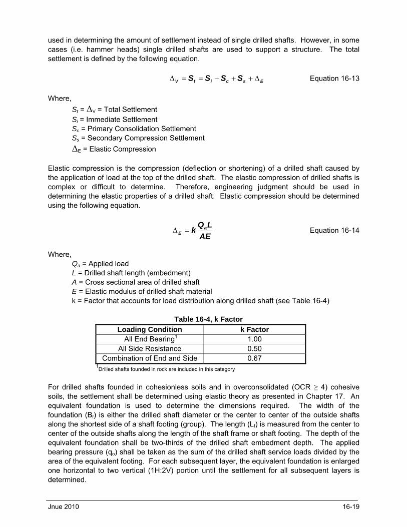
used in determining the amount of settlement instead of single drilled shafts. However, in some cases (i.e. hammer heads) single drilled shafts are used to support a structure. The total settlement is defined by the following equation.
EscitV SSSS Equation 16-13
Where,
St = ΔV = Total Settlement Si = Immediate Settlement Sc = Primary Consolidation Settlement Ss = Secondary Compression Settlement
ΔE = Elastic Compression
Elastic compression is the compression (deflection or shortening) of a drilled shaft caused by the application of load at the top of the drilled shaft. The elastic compression of drilled shafts is complex or difficult to determine. Therefore, engineering judgment should be used in determining the elastic properties of a drilled shaft. Elastic compression should be determined using the following equation.
AE
LQk a
E Equation 16-14
Where, Qa = Applied load L = Drilled shaft length (embedment) A = Cross sectional area of drilled shaft E = Elastic modulus of drilled shaft material k = Factor that accounts for load distribution along drilled shaft (see Table 16-4)
Table 16-4, k Factor
Loading Condition k Factor All End Bearing1 1.00
All Side Resistance 0.50 Combination of End and Side 0.67
1Drilled shafts founded in rock are included in this category
For drilled shafts founded in cohesionless soils and in overconsolidated (OCR ≥ 4) cohesive soils, the settlement shall be determined using elastic theory as presented in Chapter 17. An equivalent foundation is used to determine the dimensions required. The width of the foundation (Bf) is either the drilled shaft diameter or the center to center of the outside shafts along the shortest side of a shaft footing (group). The length (Lf) is measured from the center to center of the outside shafts along the length of the shaft frame or shaft footing. The depth of the equivalent foundation shall be two-thirds of the drilled shaft embedment depth. The applied bearing pressure (qo) shall be taken as the sum of the drilled shaft service loads divided by the area of the equivalent footing. For each subsequent layer, the equivalent foundation is enlarged one horizontal to two vertical (1H:2V) portion until the settlement for all subsequent layers is determined.
Jnue 2010 16-19
SCDOT Geotechnical Design Manual Deep Foundations
16-20 June 2010
The settlements for drilled shaft foundations placed in NC to slightly OC (1 < OCR <4) plastic cohesive soils shall be determined using consolidation theory as presented in Chapter 17. Similar to the elastic settlement determination an equivalent foundation shall be placed two-thirds of the drilled shaft embedment depth and the applied bearing pressures and changes in stress determined according. The applied bearing pressure (qo) shall be taken as the sum of the drilled shaft service loads divided by the area of the equivalent footing. For each subsequent layer, the equivalent foundation is enlarged one horizontal to two vertical (1H:2V) portion until the settlement for all subsequent layers is determined.
Once the total settlement (St or ΔV) is determined, then the distribution of the load between side and end should be determined as indicated previously. 16.5 DRILLED PILES
Drilled piles are constructed normally at end bents where the depth to rock is less than ten to fifteen feet. Drilled piles can be a subset of drilled shafts or driven piles depending on the strength of the rock. An RQD of less than ten percent indicates that the pile may be driven; however, refusal criteria still apply (i.e. 5 blows in ¼ inch). The capacity of the drilled pile is determined based on whether the pile is driven or not after being placed in the bore hole. Piles placed in the bore hole and not driven should be designed using drilled shaft design procedures. This design methodology requires coordination with the structural designer to ensure that adequate load transfer from the steel to the concrete occurs. Drilled piles typically consist of steel H-piles having sizes of HP12x53 and HP14x73. The borehole shall be of sufficient diameter to allow for the insertion of the pile and the placement of concrete. 16.6 CONTINUOUS FLIGHT AUGER PILES
Continuous flight auger piles (CFAs) also known as Auger Cast Piles are a new technology being considered by FHWA for transportation projects. CFAs may be used on SCDOT projects; however, CFAs may not be used to support bridges. The use of CFAs on any SCDOT project must be approved prior to completion of preliminary design. Approval shall be in writing from either the Regional Production Engineer or the Preconstruction Support Engineer. In addition, the designer shall contact the PCS/GDS for instructions on analytical methods for determining capacity. CFAs will range in size from 18 to 30 inches (1-1/2 to 2-1/2 feet, respectively) in diameter for SCDOT projects. 16.7 MICROPILES
The latest version of the AASHTO LRFD Bridge Design Specifications allows for the use of micropiles to support structures. Article 10.9 of the AASHTO LRFD Bridge Design Specifications provides a list of when micropiles would be acceptable; however, approval by either the Regional Production Engineer or the Preconstruction Support Engineer shall be obtained prior to designing micropiles. The design of micropiles when allowed shall follow Article 10.9. 16.8 LATERAL CAPACITY
Designing for lateral capacities of deep foundations consists of either lateral load tests or analytical methods. Full scale load tests will not be discussed but analytical methods will be

Jnue 2010 16-21
presented as an overview. More detailed information and the theory can be found in the FHWA publication Handbook on Design of Piles and Drilled Shafts Under Lateral Load (Reese, 1984).
Pile or shaft foundations must be designed to resist horizontal loads due to wind, traffic loads, bridge curvature, vessel or traffic impact, and seismic events. The movements or deflections as a result of the loadings should be within Performance Limits from Static or Seismic Loadings.
Methods of analysis that use manual computation include Broms’ Method. Reese developed analysis methods that model the horizontal soil resistance using P-y curves.
Deep foundation horizontal movement at the foundation design stage may be analyzed using computer applications that consider soil-structure interactions. Computer programs are available for analyzing single piles and pile groups.
According to Hannigan, et al. (1998), the design of laterally loaded piles requires the combined skills of the geotechnical and structural engineer. It is inappropriate for the geotechnical engineer to analyze a laterally loaded pile without a full understanding of pile-structure interaction. Likewise it is inappropriate for the structural engineer to complete a laterally loaded pile design without a full understanding of how pile section or spacing changes may alter the soil response. Because of the interaction of pile structural and geotechnical considerations, the economical solution of lateral pile loading problems requires communication between the structural and geotechnical engineer.
Lateral designs using static loadings are governed by the Service Limit State. For group loadings using the P-y method of analysis, P-multipliers should be used in accordance with AASHTO LRFD Bridge Design Specifications Article 10.7 – Driven Piles.
SCDOT has established a process once the final subsurface investigation has taken place and prior to issuance of the BGER. The BGER is used to design foundations for bridges and bridge related structures. For drilled shaft/pile bents and drilled shaft/pile group footings, the BGER provides estimated pile/shaft tip elevations, the minimum pile/shaft tip elevations required to maintain lateral stability (critical depth), and the necessary soil parameters to develop a P-y soil model of the subsurface that is used in performing foundation lateral soil-structure interaction analyses. The Design Team then performs the lateral soil-structure interaction analysis with computer programs such as LPILE or FB-Pier. The Design Team uses this information to compute lateral displacements and to analyze the structural adequacy of the columns and foundations. The lateral soil-structure interaction analysis is also used to select the appropriate method (point-of-fixity, stiffness matrix, linear stiffness springs, or P-y nonlinear springs) to model the bridge foundation in the structural design software.
If lateral design controls the minimum point of penetration for a deep foundation, the BGER should indicate this fact. In addition, for driven piles, the nominal capacity should be increased to account for the additional installation depth required to achieve the tip elevation governed by lateral design.
16.9 DOWNDRAG
Downdrag loads (also known as Negative Skin Resistance) can be imposed on piles and shafts where:
Sites are underlain by compressible material such as clays, silts, or organic soils,

SCDOT Geotechnical Design Manual Deep Foundations
16-22 June 2010
Fill will be or has recently been placed adjacent to the piles or shafts, such as is frequently the case for bridge approach fills,
The groundwater is substantially lowered, or,
Liquefaction of loose sandy soils can occur.
Figure 16-3: Downdrag Scenarios due to Compressible Soils and from Embankment Fills (Hannigan, et al. 1998)
The effect of downdrag loads can be mitigated thourgh the use of embankment surcharge loads, ground improvement techniques, and/or vertical drainage and settlement monitoring measurements. In addition, either coatings or sleeves/jackets may be applied to the piles allowing the soil to slide adjacent to the piles.
The following steps should be followed in determining the force effects as a result of downdrag:
(1) Establish a soil profile and properties for computing settlement.
(2) Perform settlement computation for the soil layers along the length of the pile or shaft using the procedures outlined in Chapter 17.
(3) Determine the length of pile or shaft that will be subject to downdrag. If the settlement in the soil layer is 0.4 inches or greater relative to the pile or shaft, downdrag can be assumed to fully develop; therefore, the use of residual shear strengths is required for all soils above the soil layer that experiences 0.4 inches of vertical movement.
(4) Determine the magnitude of the Downdrag (DD) load by computing the negative skin resistance (Qsdd) using static analysis procedures for cohesionless or cohesive soils as described previously for piles and shafts. Sum the negative skin resistance for all layers contributing to downdrag from the lowest layer to the bottom of pile cap or ground surface.
(5) Apply load factors (p) to the Downdrag (DD) using the load factors found in Chapter 8 for static analysis. For seismically induced Downdrag use a load factor of 1.05.
(6) For statically induced Downdrag, the Downdrag load should be added to the demand and the required factored resistance determined. This should only be done if no methods have been used to compensate for the Downdrag load (i.e. bitumen covering on pile or surcharging of the site prior to pile installation, therefore reducing relative settlement between the soil layer and foundation to less than 0.4 inches).
(7) For seismically induced Downdrag, the Downdrag load is added to the demand and compared to the nominal resistance (i.e. resistance factor ( ) is 1.0). If the nominal
resistance is greater, the driven pile or drilled shaft is acceptable. If the nominal load is less, then the driven pile or drilled shaft must be extended to obtain additional resistance to equalize demand and nominal resistance.
(8) The resistance in the soil layers that will experience Downdrag should not be included in the development of the nominal resistance of the foundation system.
(9) For driven piles, the amount of Downdrag should be added to the nominal resistance to obtain a resistance required for pile installation (i.e. Ultimate Driving Resistance). This resistance is only used in WEAP analysis and pile installation. Be sure to include any time dependent effects from the soil layer experiencing downdrag.
16.10 FOUNDATION LENGTH
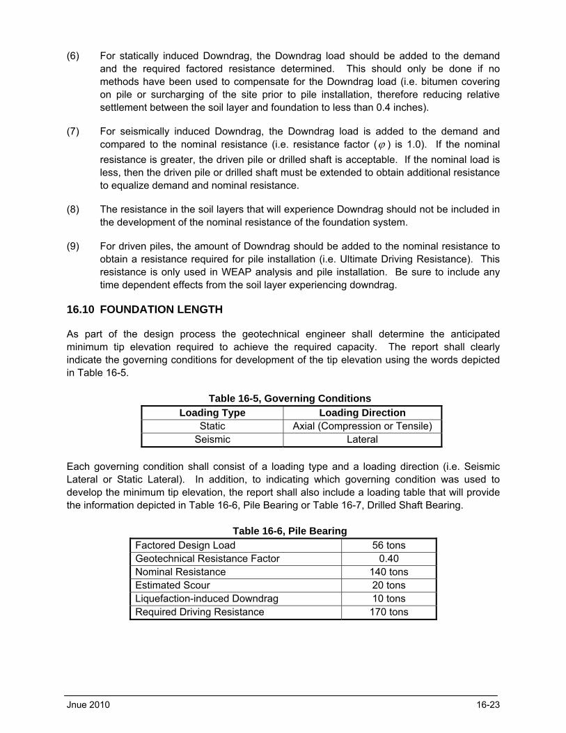
As part of the design process the geotechnical engineer shall determine the anticipated minimum tip elevation required to achieve the required capacity. The report shall clearly indicate the governing conditions for development of the tip elevation using the words depicted in Table 16-5.
Table 16-5, Governing Conditions
Loading Type Loading Direction Static Axial (Compression or Tensile)
Seismic Lateral
Each governing condition shall consist of a loading type and a loading direction (i.e. Seismic Lateral or Static Lateral). In addition, to indicating which governing condition was used to develop the minimum tip elevation, the report shall also include a loading table that will provide the information depicted in Table 16-6, Pile Bearing or Table 16-7, Drilled Shaft Bearing.
Table 16-6, Pile Bearing
Factored Design Load 56 tons Geotechnical Resistance Factor 0.40 Nominal Resistance 140 tons Estimated Scour 20 tons Liquefaction-induced Downdrag 10 tons Required Driving Resistance 170 tons
Jnue 2010 16-23

SCDOT Geotechnical Design Manual Deep Foundations
16-24 June 2010
Table 16-7, Drilled Shaft Bearing
Factored Design Load 370 tons Factored Resistance – Side 370 tons Factored Resistance – End 0 Geotechnical Resistance Factor – Side 0.50 Geotechnical Resistance Factor – End 0.50 Total Nominal Resistance 740 tons
The Ultimate Driving Resistance is used to determine the driving resistance (see Pile Drivability above) and acceptability of the driving equipment. Depending on the controlling condition this driving resistance could consist of the Nominal Resistance plus the Estimated Scour (as indicated in Table 16-4) or the driving resistance could be the Resistance required to achieve a required minimum tip elevation (i.e. the Nominal Resistance is achieved prior to reaching minimum tip elevation). In these cases the piles will be driven to a higher capacity then required to achieve the Nominal Resistance and the Pile Drivability analysis shall account for this higher required resistance. In addition, this may effect the pile driving equipment that a contractor selects. Please note that the weight of a drilled shaft is not subtracted from the nominal capacity, since the geotechnical resistance factors were obtained from static load tests. Therefore the resistance factors already account for the weight of the shaft in both compression and tension. However, depending on where the loads are applied, the weight of the column above the drilled shaft may need to be added to the axial load. The column weight is added if the loads are applied at the top of the column, however, if the loads are applied at the top of the shaft, the column weight is not added. The factored column weight shall be determined by the structural designer and provided to the geotechnical engineer. In addition, the structural designer shall indicate where the loads are applied on the load data sheet. If the Downdrag loads exceed the Nominal Resistance of the deep foundation, then additional length will be required. For driven piles this additional length shall be accounted for in the Ultimate Driving Resistance. For drilled shafts that tip elevation shall be changed to reflect this increase and an Ultimate Bearing Resistance shall be indicated on the plans. 16.11 REFERENCES
American Association of State Highway and Transportation Officials, AASHTO LRFD Bridge Design Specifications Customary U.S. Units, 4th Edition, dated 2007 with 2008 Interim Revisions, Washington, D.C. Bowles, J. E., (1986), Foundation Analysis and Design, Fifth Edition, The McGraw-Hill Companies, Inc. Department of the Navy, Naval Facilities Engineering Command, (1982), Soil Mechanics – Design Manual 7.1, Publication No. NAVFAC DM-7.1, Alexandria, Virginia. Department of the Navy, Naval Facilities Engineering Command, (1986), Foundations and Earth Structures 7.2, Publication No. NAVFAC DM-7.2, Alexandria, Virginia.
Jnue 2010 16-25
Hannigan, P. J., Goble, G. G., Likins, G. E., and Rausche, F., (2006). Design and Construction of Driven Pile Foundations – Volume I and II, FHWA Publication No. FHWA-NHI-05-042. U.S. Department of Transportation, Federal Highway Administration, Washington D.C. Kyfor, Z. G., Schnore, A. R., Carlo, T. A. and Bailey, P. F., (1992). Static Testing of Deep Foundations, FHWA Publication No. FHWA-SA-091-042. U.S. Department of Transportation, Federal Highway Administration, Washington D.C. O’Neil, M. W. and Reese, L. C. (1999), Drilled Shafts: Construction Procedures and Design Methods, FHWA Publication No. FHWA-IF-99-025. U.S. Department of Transportation, Federal Highway Administration, Washington D.C. Reese, L. C., (1984), Handbook on Design of Piles and Drilled Shafts Under Lateral Loads, FHWA Publication No. FHWA-IP-84-11. U.S. Department of Transportation, Federal Highway Administration, Washington D.C. South Carolina Department of Transportation, Bridge Design Manual, dated April 2006. US Department of Transportation, Office of Bridge Technology, Federal Highway Administration, Geotechnical Engineering Circular No. 6 – Shallow Foundations, dated September 2002 (Publication No. FHWA-SA-02-054), Washington, D.C.