chapter 15 university of massachusetts at lowell
TRANSCRIPT

249
CHAPTER 15 UNIVERSITY OF MASSACHUSETTS AT
LOWELL Department of Electrical and Computer Engineering
University of Massachusetts Lowell, Lowell, MA 01854
Principal Investigator: Dr. Donn Clark (978) 934-3341

250 NSF 2004 Engineering Senior Design Projects to Aid Persons with Disabilities
VOICE ACTIVATED TV REMOTE CONTROL Designer: Abdel Kader Diagne Supervisor: Walter McGuire
Department of Electrical & Computer Engineering University Avenue
Lowell, Massachusetts 01854
INTRODUCTION The object of this project was to design a voice activated television remote control that can help individuals who are physically challenged. The aim was to help a client with quadriplegia operate his TV by having a voice command remote operate most of the useful functions.
SUMMARY OF IMPACT This project is to help individuals who have quadriplegia and any other individual who needs assistance in operating certain electronic devices. This device will allow a user to take advantage of five different functions such as volume control, channel control, and power control. This device is easy to operate.
TECHNICAL DESCRIPTION The HM2007 voice recognition chip has six control functions of which four were used in this project: recog, train, result, and reset. In addition the HM2007, in the CPU mode, has a K bus and S bus which are connected to the I/O pins of the microcontroller through the receivers. When the microcontroller sends the train command to the HM2007, it begins training for a selected word. The recog command causes the HM2007 to initiate the recognition process for the word spoken into the microphone. The result command causes the HM2007 to send the recognition result to the microcontroller. The reset command will clear the patterns in the SRAM of the HM2007. Once the training mode is completed, the normal operating mode is as follows. When the user issues a voice command, the voice recognition system processes the voice input and sends the results of the recognition to the control unit.
The digital output is then selected through a four-line –to 16 line decoder which utilizes TTl circuitry to decode four binary –coded inputs into one of the sixteen mutually exclusive outputs when both the strobe inputs G1 and G2 are low. The de-multiplexing function is performed by using the four input lines to address the output line, passing data from one of the strobe inputs with the other strobe input low. When either strobe input is High, all outputs are high. These de-muxtiplexers are ideally suited for implementing high- performance memory decoders. All inputs are buffered and input clamping diodes are provided to minimize transmission line effects and thereby simplify system design.
The selected low output from the de-mux is fed into a one-shot timer. Upon applying power to it, the load is energized and the time delay cycle is initiated. At the end of the delay time, the load is de-energized. One could reset it just by removing the input power. The purpose of using the one-shot timer is to delay the input signal so that there is no need for several calls to activate a function at the remote end.
The output from the one-shot timer is connected to the base terminal of a bipolar junction transistor to pull down a relay switch in parallel with functions of a universal TV remote control.
The device was successfully completed and tested with a Sony TV. Future work will address the problem encountered with the HM2007, including its poor performance in noisy environments.

Chapter 14: University of Massachusetts Lowell 251
Figure 15.1. Voice Activated TV Remote Control.
252 NSF 2004 Engineering Senior Design Projects to Aid Persons with Disabilities
PRESSURE ACTIVATED LIGHT PAD Designer: Akhuemose Otez
Client Coordinator: Tracey Ruth, Lowell High School, Lowell, MA Supervising Professor: Walter McGuire
Department of Electrical and Computer Engineering, University of Massachusetts at Lowell
Lowell, MA 01854
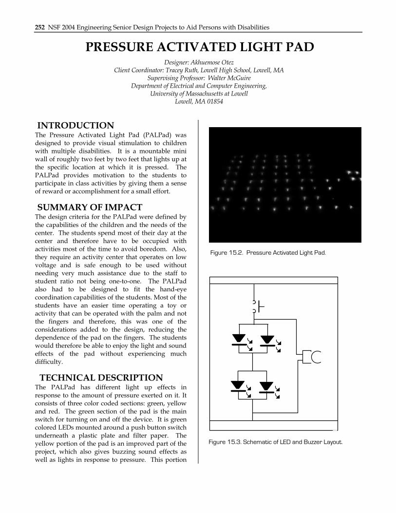
INTRODUCTION The Pressure Activated Light Pad (PALPad) was designed to provide visual stimulation to children with multiple disabilities. It is a mountable mini wall of roughly two feet by two feet that lights up at the specific location at which it is pressed. The PALPad provides motivation to the students to participate in class activities by giving them a sense of reward or accomplishment for a small effort.
SUMMARY OF IMPACT The design criteria for the PALPad were defined by the capabilities of the children and the needs of the center. The students spend most of their day at the center and therefore have to be occupied with activities most of the time to avoid boredom. Also, they require an activity center that operates on low voltage and is safe enough to be used without needing very much assistance due to the staff to student ratio not being one-to-one. The PALPad also had to be designed to fit the hand-eye coordination capabilities of the students. Most of the students have an easier time operating a toy or activity that can be operated with the palm and not the fingers and therefore, this was one of the considerations added to the design, reducing the dependence of the pad on the fingers. The students would therefore be able to enjoy the light and sound effects of the pad without experiencing much difficulty.
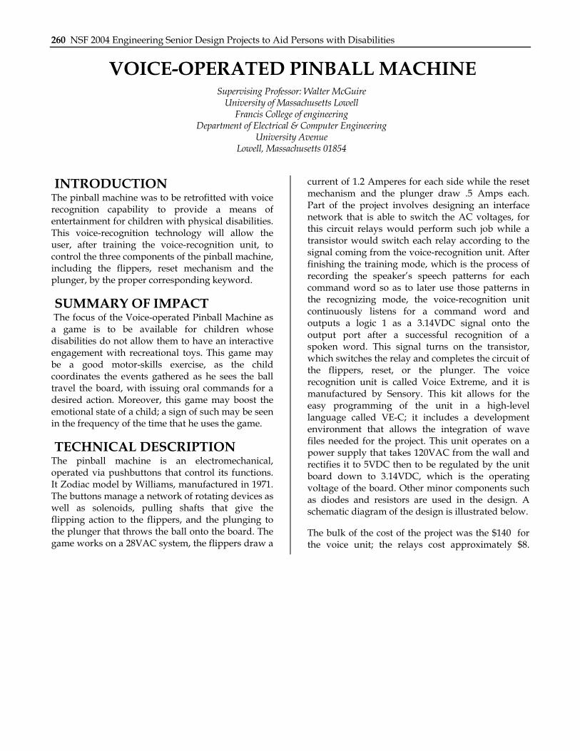
TECHNICAL DESCRIPTION The PALPad has different light up effects in response to the amount of pressure exerted on it. It consists of three color coded sections: green, yellow and red. The green section of the pad is the main switch for turning on and off the device. It is green colored LEDs mounted around a push button switch underneath a plastic plate and filter paper. The yellow portion of the pad is an improved part of the project, which also gives buzzing sound effects as well as lights in response to pressure. This portion
Figure 15.2. Pressure Activated Light Pad.
BY: ANDREW DOUGLAS MACFARLANE
Figure 15.3. Schematic of LED and Buzzer Layout.

Chapter 14: University of Massachusetts Lowell 253
is made up of momentary switches which go off as soon as the pressure on them is released. That way, the buzzing sounds can also go off as soon as the switches are released. The red part of the project is the main objective of the PALPad, which responds to pressure on a different level. It is made up of red LEDs mounted around “soft-feel” push-on-push-off switches. These switches respond to the slightest pressure and act like momentary switches when not enough pressure is exerted on them. The red LEDs light up as soon as this portion is pressed and can go off immediately after the pressure is released, or stay on depending on how much pressure is put on them. This part of the PALPad maintains its pattern if enough pressure is exerted on it even after the main switch is turned off and on again. The red LEDs only turn off when the exact location is
pressed again. This pad can keep a student occupied for quite a while as he enjoys the light displays and sounds.
The PALPad is a parallel combination of switches, light emitting diodes (LEDs), buzzers and sound circuitry. One light connection is duplicated 16 times to give the full grid of red lights. The orange section of the pad had an additional buzzer connected in parallel across the LEDs below the push switch as shown in Figure 15.3.
The circuit for the sound generator is a little more complex than above, consisting of an SG3 chip, a resistor, some capacitors, and a transistor as shown in Figure 15.4
The cost of parts/material is about $300.
C3
SPEAKER
LED
390KR1
18uf C310uf
TRIGGER
S63
NCNC
NC
C28 lvf
01
123456789
1011121314
Figure 15.4. Schematic of Sound Generator.

254 NSF 2004 Engineering Senior Design Projects to Aid Persons with Disabilities
SHAPE SORTER WITH RECORDABLE MESSAGES AND LED BLINKING ACTIVITY
Designer: Antonios Bousios Client Coordinator: Dr. T. Opperman, Lowell High School Intensive Needs Program, Lowell MA
Supervising Instructor: Mr. Walter McGuire Department of Electrical and Computer Engineering
1 University Avenue Lowell, Massachusetts 01854
INTRODUCTION A musical shape sorter, called the Shape Pro, was designed to improve the motor skills of students with disabilities. The device consists of four removable shapes; each shape has its own specific color which also helps in color coordination. These shapes must be inserted in the correct position in order to get sound and light feedback to the user. There are 20 LEDs positioned around the device with a speaker in the middle. Unlike other shape sorters on the market this device gives the users the opportunity to record their own messages. Another additional feature added to the device is the ability to control the rate at which the LED’s blink.
SUMMARY OF IMPACT The Shape Pro will help the children and the physical therapists at a high school by introducing a new learning tool. The client will be able to play with the toy by himself while the physical therapist tends to other children. The device can also be used by a group of students, or by a student teacher group, depending on the needs of the child.
TECHNICAL DESCRIPTION The device consists of an ISD1420 voice recording chip, a set of 4017 decade counters, four photo-reflective sensors, and two 74221 Dual Monostable
Multivibrator. The photo-reflective sensors can sense a reflective object within a five-millimeter distance. The output of the sensors is sent to the input of the corresponding monostable multivibrator which then sends a pulse to the ISD via a four-input AND gate. This pulse initiates a playback sequence. The ISD1420 can store up to 20 seconds of sound from a microphone input. It has a non-volatile memory which means the device does not need a battery backup. The decade counters are controlled by the speaker output pins of the ISD1420. When there is sound output, the LED’s begin flashing. This is accomplished by connecting the speaker pins through an NPN transistor to the reset pins of the 4017. When the reset pins are high the counter is in an idle state. When the reset pins are low, the counter begins to advance depending on the rising edges of the clock pulse. The clock is supplied by an LM555 timer which has a variable resistor in place to allow the user to adjust the LED blinking frequency. The circuit also contains a tri state buffer and LM555 timer to block any input to the ISD until all devices have powered up, a two second delay gives enough time for all circuits to come up to operating voltage. This is done to prevent unexpected playbacks on power-up.
The total cost of the projects parts and materials is approximately $30.

Chapter 14: University of Massachusetts Lowell 255
Figure 15.5. Shape Pro.

256 NSF 2004 Engineering Senior Design Projects to Aid Persons with Disabilities
VOICE ACTIVATED SPEAKERPHONE Designer: Bishal Nepal
Client Coordinator: Alan Rux, UMASS Lowell Supervising Professor: Walter McGuire
Electrical and Computer Engineering Department University of Massachusetts Lowell,
Lowell, Massachusetts 01804
INTRODUCTION The voice-activated speakerphone is designed to enable phone conversation for an individual who is unable to pick up and hang up the phone because of a physical disability. This device requires a simple modification of a regular phone by projecting a switch for the speakerphone externally so that it can be stimulated by a desired external event such as voice. After designing this device, an individual does not need manual movement for receiving and hanging up a telephone.
SUMMARY OF IMPACT The design was requested by a client who has scleroderma, a disease that causes contraction of skin, restricting body movement during peak reactions. She requested a phone that did not require manual lifting and hanging up.
TECHNICAL DESCRIPTION The first step of the project requires modification of an existing telephone so that the speakerphone can be controlled remotely without lifting and hanging up the phone. Secondly, it requires a circuit that answers and hangs up a telephone by the use of either voice or sound. This telephone will be connected to the circuit that delivers the switching function by taking voice input. The microphone and speaker are also modified to make them user accessible.
In order to make the speakerphone voice activated, the keypad is modified. A keypad consists of several short circuits. Once a short circuit is completed, it creates an impulse that performs essential functions. Numeric keypad create DTMF tones, which completes telephone dialing. Dual Tone Multi Frequency (DTMF) is known as Touch Tones, an example of multi-frequency shift keying. In order to activate the speakerphone externally, wires are taken from short circuit keypad and
projected externally. A hole is drilled in the telephone case and a jack is used.
The structure of relay controller is a black box which is 10x 6 x 4 inches. A circuit board is mounted inside
Figure 15.6. The Voice Activated Speakerphone.
Figure 15.7. Additional Picture.

Chapter 14: University of Massachusetts Lowell 257
the box. Jacks are installed for power, relay switching and microphone operation. The circuit board operates with 9-12 volts DC which are provided with either battery or wall current. A 12V DC adapter is used to provide power to the circuit.
This part of the circuit is connected to the jack that is being projected externally off the keypad. In this circuit, a microphone picks up audio signal and it is fed into operational amplifier LM358N. This is connected as a non-inverting amplifier with a gain of 151 or +43.6 dB. RF is eliminated by a 100pF capacitor across 150K feedback resistor that rolls of the high frequency above 10KHz. The output pin 1 feeds to diodes D1 and D2 which functions as a half-wave voltage doubler. These rectify the audio signal to produce a DC voltage across the 2.2uF ecap, C2 which is directly proportional to the input audio sound level.
This DC voltage is fed to pin 5 of the Op Amp. This is connected as a comparator. A resistive voltage divider applies about 2V to pin 6. Once the DC voltage across the 2.2uF ecap rises above the voltage at pin 6, pin 7 pulls high. This turns on the transistor Q1 which activates the relay and turns on the LED. Q1 remains on while the DC voltage at pin 5 is about that at pin 6. The high op-amp gains if IC1a, the voltage doubler gains the circuit and has a fast response time. The release time takes about
three seconds which is determined by the time constant of C2 and R5 and the pin 6 threshold voltage. D1 is connected across the relay to protect Q1 when the relay turns off. A 12V power is used. D4 is a protection for the circuit in case power is connected the wrong way. Sensitivity of the microphone is varied with the 200K trimpot. The off delay time is adjusted by varying R3 and R4. Reducing R3 results in longer release time.
The cost of parts and material is approximately $108.
LED
C4 100p
R939K R6
200KSENSITIVITY
R71K
C52u2
MIC
R810k IC1: A
LM358C3104
C110u
D31N4148
R410K
R11K
D11N4004
D41N4004
12VDRELAYAZ-SH-112L
Q1BC548
R210K
D2 C22u2
1N4148
R51M
R3
2K2
IC1:BLM358
Figure 15.8. Voice Activated Relay Controller.
Figure 15.9. Phone and Relay Circuit Interface.

258 NSF 2004 Engineering Senior Design Projects to Aid Persons with Disabilities
AUTOMATED TOOTHBRUSH Designer: Nicole DeCalogero
Client Coordinator, Nashua High School Nashua, NH Professor Walter McGuire, Professor Wade – Supervising Professors
Department of Electrical & Computer Engineering University Avenue
Lowell, Massachusetts 01854
INTRODUCTION An automated toothbrush was designed for a young man with Duchenne muscular dystrophy, an incurable genetic progressive disorder. He uses an automated wheelchair that he controls with a joystick. He has limited range of motion in his upper body, but has excellent cognitive skills and is able to play video games and operate a game controller. Prior to having this device, the client relied on his family for hygiene assistance – including brushing his teeth once in the morning and once at night.
Nothing on the market was found that the client was able to manipulate, given his limited range of motion. While there are battery operated toothbrushes on the market, the client could not hold the toothbrush in the correct position or grasp it with enough agility to control his motions. Therefore, an electrical and mechanical device was designed that mounts onto his wheelchair and supports an automated toothbrush. He can control all aspects of this movable brushing system (including a shut-off switch) with one small homemade controller.
SUMMARY OF IMPACT The client still requires assistance setting up the frame onto his wheelchair and loading the brush with toothpaste. Once set up, however, he can brush his teeth for as long as he chooses. When he used it for the first time, he said, “this is so cool!” and “I’ll be able to brush before bed all by myself now.” It should be noted that this automated toothbrush will be especially useful in the client’s household as his brother also has MD and similar physical limitations. The disposable, replaceable head of the toothbrush makes it a versatile tool that both brothers can use.
TECHNICAL DESCRIPTION A servo pulsing circuit is the basis for this project. An LM555 timer was the IC chosen to make the required pulse train. This timer is chosen for its application of pulse width modulation. The 10k trimpot changes the pulse width. As the potentiometer is varied, the pulse width varies from one millisecond to two milliseconds. The resistor R1 is a shunt resistor that only allows the correct amount of current to pass into R2 that is sufficient enough to derive a pulse from one millisecond to two milliseconds. The output of the 555 (PIN 3) is connected to the white (control) wire of the servo motor. This is the pulse train that the servo needs in order to position itself properly.
The blocking circuit is implemented using basic logic design. An AND gate provides the proper logic output needed to implement this function. The inputs of the AND gate, and the Vcc are all tied to the positive terminal of the toothbrush motor just after the SPST toothbrush activation switch. The output of the AND gate is connected to the Threshold pin of the 555 timer which is also tied to the Trigger pin of the 555. The Reset pin of the 555 timer is changed to not being connected in order to give the circuit the proper operation. If the toothbrush is placed in the ON position than the AND gate sees two active high signals at the input side, and outputs an active high signal to the Trigger pin of the 555. When the Trigger pin of the 555 receives an active high signal from the AND gate it does not continue to produce a pulse to the servo motor therefore not allowing it to turn. If the brush is OFF than the AND gate is not in operation, and the Trigger pin sees no difference in signals, therefore it continues to operate sending a pulse to the servo motor allowing it to turn.
There are two safety switches that cut off power to the entire system. In order for the switches to cut power to the entire system they had to be placed closest to the +Vcc source. Each switch is mounted

Chapter 14: University of Massachusetts Lowell 259
in line with the +Vcc feed line, and has a green LED mounted between the switch side and ground.
All of the electronics of the system are mounted inside of the main electronics box with the exception of Switch 1 (the toothbrush activation switch), Switch 2 (safety shut down switch), D2 (Green LED), and the 10k potentiometer P1. The main box is a 4x4x4 inch PVC wet location junction box. The box is cut in half to make it stand 2.5 inches high. The box is waterproof and has a screw cover with rubber gasket. All of the electronics are soldered to an IC board and mounted inside of this box. One of the main safety switches is mounted to the top of this box along with a green LED. Three wires come out of the main box and are used for; power supply, toothbrush activation, and the remote control. All wires coming out of the box are coated with silicon sealant at the point of exit to ensure watertight integrity. Four rubber feet are adhered to the
bottom of the box to keep it from sliding off of any surface.
The remote control is wired directly into the main electronics box with 24/4 pair CAT 3 cable. The remote is made from a small 3x2x1 inch project box. The components found on the remote are Switch 1 (toothbrush activation switch), Switch 2 (safety shut down switch), D2 (green LED), and the 10kΩ potentiometer P1. These components are drilled into and mounted to the surface of the project box. All wiring of these components is completed internal to the box, and the box is sealed with silicon sealant to produce watertight integrity. The remote control is the only means to operate the toothbrush on/off power, and to turn the servo motor.
The total cost for parts is $121.94.
.
260 NSF 2004 Engineering Senior Design Projects to Aid Persons with Disabilities
VOICE-OPERATED PINBALL MACHINE Supervising Professor: Walter McGuire
University of Massachusetts Lowell Francis College of engineering
Department of Electrical & Computer Engineering University Avenue
Lowell, Massachusetts 01854
INTRODUCTION The pinball machine was to be retrofitted with voice recognition capability to provide a means of entertainment for children with physical disabilities. This voice-recognition technology will allow the user, after training the voice-recognition unit, to control the three components of the pinball machine, including the flippers, reset mechanism and the plunger, by the proper corresponding keyword.
SUMMARY OF IMPACT The focus of the Voice-operated Pinball Machine as a game is to be available for children whose disabilities do not allow them to have an interactive engagement with recreational toys. This game may be a good motor-skills exercise, as the child coordinates the events gathered as he sees the ball travel the board, with issuing oral commands for a desired action. Moreover, this game may boost the emotional state of a child; a sign of such may be seen in the frequency of the time that he uses the game.
TECHNICAL DESCRIPTION The pinball machine is an electromechanical, operated via pushbuttons that control its functions. It Zodiac model by Williams, manufactured in 1971. The buttons manage a network of rotating devices as well as solenoids, pulling shafts that give the flipping action to the flippers, and the plunging to the plunger that throws the ball onto the board. The game works on a 28VAC system, the flippers draw a
current of 1.2 Amperes for each side while the reset mechanism and the plunger draw .5 Amps each. Part of the project involves designing an interface network that is able to switch the AC voltages, for this circuit relays would perform such job while a transistor would switch each relay according to the signal coming from the voice-recognition unit. After finishing the training mode, which is the process of recording the speaker’s speech patterns for each command word so as to later use those patterns in the recognizing mode, the voice-recognition unit continuously listens for a command word and outputs a logic 1 as a 3.14VDC signal onto the output port after a successful recognition of a spoken word. This signal turns on the transistor, which switches the relay and completes the circuit of the flippers, reset, or the plunger. The voice recognition unit is called Voice Extreme, and it is manufactured by Sensory. This kit allows for the easy programming of the unit in a high-level language called VE-C; it includes a development environment that allows the integration of wave files needed for the project. This unit operates on a power supply that takes 120VAC from the wall and rectifies it to 5VDC then to be regulated by the unit board down to 3.14VDC, which is the operating voltage of the board. Other minor components such as diodes and resistors are used in the design. A schematic diagram of the design is illustrated below.
The bulk of the cost of the project was the $140 for the voice unit; the relays cost approximately $8.
Chapter 14: University of Massachusetts Lowell 261
BUBBLE LAMP CAUSE AND EFFECT DEVICE Designers: Edwin Corporan
Client Coordinator: Lowell High School, Department Of Special Education Supervising Professor: Jay Fu and Alan Rux
Electrical and Computer Engineering Department University Of Massachusetts at Lowell,
Lowell, MA 01854
INTRODUCTION The 'Bubble Lamp' was designed to help teach cause and effect to individuals with cognitive disabilities. The project consists of a water bubble lamp that generates bubbles, different color water, and different colors of light. It contains plastic fishes that swim around for a period of 5.6 seconds after a jelly bean switch is pressed. This is accomplished with capacitors, resistors, a 9V battery, a 120 AC power supply, an AC motor, an AC light bulb, an AC water pump, a relay, a phone jack adapter, a jelly bean switch, and a 555 timer IC.
SUMMARY OF IMPACT The goal of this project was to build a fun and easy-to -use learning tool to teach cause and affect. This will enhance learning, allow teachers time to attend to other students who may need more attention, and provide a fun activity with which children can learn and play at the same time.
TECHNICAL DESCRIPTION The lamp chosen for this project is a 3 feet tall and 4 inch wide spiral tubular model with a 1 foot tall, one foot wide circular base. All electronic components,
except for the jelly bean switch are placed inside the base of the lamp.
By pressing the jelly bean switch, an input signal is send to an active low 555 timer. By using a 5.6 M ohm resistor and a one uf capacitor an output pulse is created by the 555 timer for a period of 5.6 seconds. This pulse is then sent to a 5 VDC/120VAC relay where it will create a closing path for the current to flow in the AC components of the lamp. In other words, once the relay is triggered it activates an AC motor, air pump, and light bulb for a period of 5.6 seconds. The bubbles generated by the air pump enable the fish inside the lamp to swim for 5.6 seconds. In conjunction with the air bubbles, an AC motor rotates around a piece of plastic that is divided into different color sections. At the same time the AC light bulb in collaboration with the motor, generates different colored lights. As the fish swim around, different colored lights will be displayed in the water for 5.6 seconds.
The cost of parts/material was about $109.
262 NSF 2004 Engineering Senior Design Projects to Aid Persons with Disabilities
TALKING CLOCK Designer: David Harris
Client Coordinator: Ms. Judy McGrath Supervising Professor: Jay Fu
Electrical and Computer Engineering Department University of Massachusetts Lowell
Lowell, MA 01854
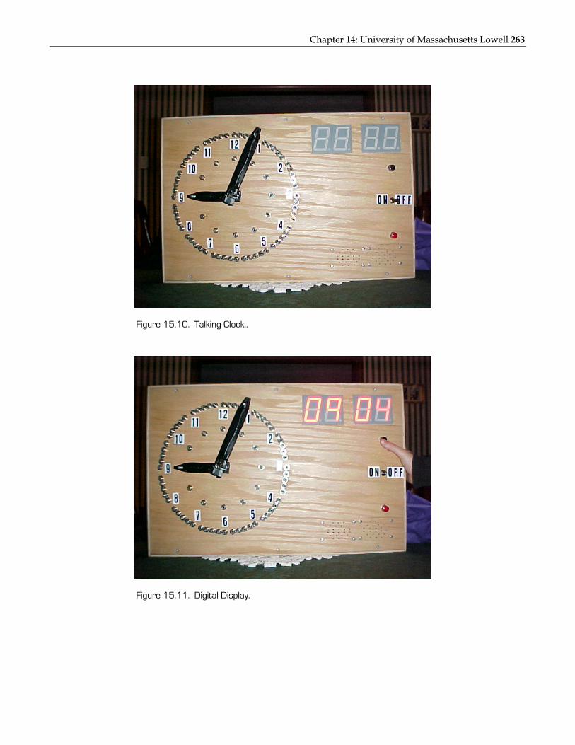
INTRODUCTION The “Talking Clock" (Figure 15.10) is a device that allows a user to set the time of an analog clock and have that time read back to them in words through a speaker. The user will also have the capability to see a digital readout of that time. This process will help the user learn how to read an analog clock. The Talking Clock is specifically designed for a special needs classroom.
SUMMARY OF IMPACT The design criteria for the talking clock were specified by the client coordinator. The clock had to be safe for the children to use independently. Also, the speed of the voice could not be too fast, and the device had to run off batteries. Ideally, the device will help children with special needs learn to read analog clocks.
TECHNICAL DESCRIPTION The material used in for the enclosure is quarter-inch finished plywood. The dimensions are as follows 24 inches by 16 inches by 4 inches. The box is drilled and cut for the components that need to be mounted to it. All of the wood is sanded down for safety reasons and then coated with polyurethane to protect the wood.
The power for the project comes from two sources. There is a battery pack for 4 D cell batteries, which is mounted on the bottom of the enclosure that powers all of the circuitry. There is also a 9V battery which just powers the digital readout. A range of 4.5 to 6V works for most digital circuits, but because of the high power output needed to light the large seven segment displays the 9V battery was added.
The hours and minutes are activated using an electronic circuit that encoded the time set buy the user and addresses it to a segment of voice recorded to an ISD Voice Record/Playback Intergraded Circuit. The hour voice is recoded to one IC and the minute to another.
In order to activate both the hour and the minute by a single pushbutton, a time delay circuit is needed so that the user could hear the hour first followed by the minute. This is accomplished by integrating a 555 timer circuit.
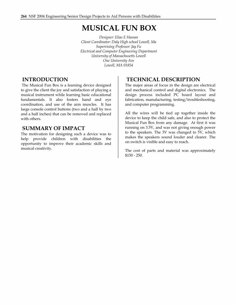
The last aspect of the project is to output the set time to a digital display. This is accomplished by taking the encoded output and bringing this to four Binary Coded Decimal to Seven Segment Display ICs. The display is shown in Figure 15.11
The cost of parts and material was approximately $275.
Chapter 14: University of Massachusetts Lowell 263
Figure 15.10. Talking Clock..
Figure 15.11. Digital Display.
264 NSF 2004 Engineering Senior Design Projects to Aid Persons with Disabilities
MUSICAL FUN BOX Designer: Elias E Hassan
Client Coordinator: Daly High school Lowell, Ma Supervising Professor: Jay Fu
Electrical and Computer Engineering Department University of Massachusetts Lowell
One University Ave Lowell, MA 01854
INTRODUCTION The Musical Fun Box is a learning device designed to give the client the joy and satisfaction of playing a musical instrument while learning basic educational fundamentals. It also fosters hand and eye coordination, and use of the arm muscles. It has large console control buttons (two and a half by two and a half inches) that can be removed and replaced with others.
SUMMARY OF IMPACT The motivation for designing such a device was to help provide children with disabilities the opportunity to improve their academic skills and musical creativity.
TECHNICAL DESCRIPTION The major areas of focus in the design are electrical and mechanical control and digital electronics. The design process included PC board layout and fabrication, manufacturing, testing/troubleshooting, and computer programming.
All the wires will be tied up together inside the device to keep the child safe, and also to protect the Musical Fun Box from any damage. At first it was running on 3.5V, and was not giving enough power to the speakers. The 3V was changed to 5V, which makes the speakers sound louder and clearer. The on switch is visible and easy to reach.
The cost of parts and material was approximately $150 - 250.

Chapter 14: University of Massachusetts Lowell 265
Figure 15.12. The Musical Learning Device.
Figure 15.13. Block Diagram.

266 NSF 2004 Engineering Senior Design Projects to Aid Persons with Disabilities
THE WIRELESS WHEELCHAIR TABLE SWITCH Designer: Gerard Chua
Client Coordinator: Jennifer MacDonald, New England Pediatric Care, Billerica, MA Supervising Professor: Walter McGuire
Electrical and Computer Engineering Department University of Massachusetts Lowell
1 University Ave Lowell, MA 01854
INTRODUCTION The wireless wheelchair table switch is designed to provide additional mobility to individuals with disabilities. The switch consists of a wireless RF transmitter attached to a wheelchair table with two big switches firmly attached on top with the wires concealed under the table cover. The matching wireless receiver provides a range of over 50 feet of mobility to replace traditional wired switches. The device is designed for a client who requires the use of switches to activate toys and electrical devices. There could not be any exposed wires as he tends to chew on them. This device’s design philosophy is based on simplicity and ease of implementation.
SUMMARY OF IMPACT An important design criterion for the wireless wheelchair table switch is that the final product must not have any exposed wires. The switch enables the client to activate devices independently such as the radio or television without the need for constant supervision by the care provider. The wireless switch is also used as an educational tool as it allows the client to learn to make choices and provide fulfillment because the client is able to have control over when he wants to activate certain devices.
TECHNICAL DESCRIPTION The RF components of the wireless switch consist of a matching transmitter and receiver by Linx Technologies. The transmitter used is the TXE-433-KH 433MHz transmitter with on-board encoder and the receiver was the RXD-433-KH 433MHz receiver with on-board decoder. Both the transmitter and receiver use the ANT-433-SP “Splatch” planar antenna.
The KH series of transmitters and receivers from Linx Technologies is used as it needs little or no other external RF components except the antenna.
This allows ease and simplification of design, allowing the device to be as compact as possible. It also provides several important features on-board a single chip each. The encoder and decoder on-board the transmitter and receiver respectively allow one to eight parallel binary inputs and outputs for direct connection to peripherals. It has 310 address lines that provide security and allows for unique transmitter and receiver relationships that reduces contention and interference. The ultra-low power consumption of the components allows for a longer battery life, and the typical operating voltage needed was only three VDC.
The KH series uses a stable and highly optimized Surface Acoustic Wave (SAW) architecture. This allows the transmitter to achieve high fundamental output power with low harmonic content and the receiver’s pass opening to be quite narrow thus increasing sensitivity and reducing susceptibility to near-band interference.
To enable the onboard encoder, the Transmit Enable line of the transmitter had to be taken high. The
Figure 15.14. Wireless Receiver (left) and Transmitter (Right) with Switches.
Chapter 14: University of Massachusetts Lowell 267
encoder then detects the logic states of the data and address lines of the IC and these states are formatted into a three-word transmission cycle which continues until the Transmit Enable line is taken low. The project requirements call for two switches to be connected to the transmitter, thus only the first two data inputs of the usable eight are used in this project. The remaining inputs are left floating; the corresponding data output of the receiver are also left floating. Each data input line is independent of the other.
The two data lines are connected to VCC through their respective switches. Therefore, when the switch is pressed, the input detects a high logic state.
The inputs are tied to the Transmit Enable pin through a dual-input OR gate acting as a buffer.
When data are received on the receiver module, the incoming address data is compared with the local address settings. If the addresses are different, the data are tossed out and ignored. If the address data are identical, the receiver module’s eight data outputs are set to replicate the state of the transmitter’s data input lines. In addition, the Transmission Verify pin goes high to indicate reception and decoding of data. The two output data lines used are each connected to a NPN transistor switch. The transistor switch is connected to an eighth-inch standard mono jack.

268 NSF 2004 Engineering Senior Design Projects to Aid Persons with Disabilities
TWO-BUTTON TELEVISION REMOTE Designer: Gladys Kirubi
Supervising professor: Jay Fu Department of Electrical and Computer Engineering
1 University Avenue University of Massachusetts Lowell
Lowell, MA 01854
INTRODUCTION A simple TV remote was designed for an intelligent 12-year-old child who is not able to walk and uses a powered wheelchair. Due to limited strength and coordination, he requested a simplified TV remote with just two large control buttons and an infrared signal that could be detected anywhere in the room.
SUMMARY OF IMPACT Since the client can only use his elbow to turn the TV ON/OFF or change the channels, the regular remote control does not work for him. The jelly bean buttons are ideal because they are big and thus easier to push. They also reduce the chance of his making a wrong choice on the remote control.
TECHNICAL DESCRIPTION An existing remote control was modified to suit the client’s needs. The TV remote has the power and Channel UP and DOWN connected to the designed circuit to allow the client to use the jelly bean buttons instead.
The switch is connected to a DM74LS21 one shot that creates a pulse. This is connected to a flip flop that is either on or off depending on the option selected. The FF output is an input to an AND gate whose other input is a 555 timer. This increments the counter that is decoded by a 4/16 DM74154. The decoder is connected to a transistor, which is connected to an LED (three different kinds for ON/OFF, Channel Up and Down). Depending on which LED turns on, the output of the decoder connects to another flip flop. This is a D flip flop that has a clock. This running clock comes from the 555 timer. This is connected to an AND gate that turns the one-shot circuit. This one-shot turns a relay ON and OFF. The relay is then connected to the TV remote control and this sends the desired message to the TV. To communicate with the TV, the user has to press the jelly button twice. The first time it starts the sequence of turning the LEDs and if the desired LED came on, the user has to press the jelly bean button and either turn on the TV or change the channels.

Chapter 14: University of Massachusetts Lowell 269
Figure 15.15. TV Remote Control.

270 NSF 2004 Engineering Senior Design Projects to Aid Persons with Disabilities
SENSORY STIMULATION GYM Designers: Gregg Forsythe
Client Coordinator: Debby Webster Supervising Professor: Dr. Walter McGuire
Electrical and Computer Engineering Department State University of Massachusetts at Lowell,
Lowell, MA 01854
INTRODUCTION The sensory stimulation gym is designed to provide stimulation for children with multiple disabilities. The device is an activity desk (Figure 15.16) with an opening big enough for an electric wheel chair. On the top of the desk, within reach of the children, are varied activities. Once the child performs one of the activities, sensory feedback is activated.
SUMMARY OF IMPACT The physical therapists at the school are often busy tending to all the students, and as a result, are unable to spend long periods of time with any one child. To resolve this problem, they requested an activity center to which they can wheel a student, letting him or her play as they tend to other students. Three different senses are stimulated and the user experiences a sense of control.
TECHNICAL DESCRIPTION The gym is constructed from sturdy metal workbench legs with a wooden kitchen tabletop. The desk (44 inches long by 27.5 inches wide, and 32 inches high) is capable of supporting the weight of a full-grown person. All additional components are mounted to top of the desk.
The exercises are four horn push buttons, each big enough for an entire hand to fit on, and one toggle switch, big enough to be hit with the back of a hand. The switches activate two different items, depending on which way each is hit. The circuit is wired as follows: One horn button turns on the two blue utility lights. The second horn button turns on the two red utility lights. The third horn button turns on the back-up alarm and the two amber utility lights. The fourth horn button turns on the amber strobe light. If the plow switch is hit forward, it turns on the two white utility lights, and if it is hit back it turns on the car fan.
The power source for this project is a power adapter that takes a 120 VAC and outputs a max of one amp and 12 VDC. The adapter is carefully selected to be safe to humans and be enough to power all the components. All the wiring is kept in the back of the desk away from the students. All the wires and power adapter are fastened to the bottom of the desk.
Figure 15.16. Sensory Stimulation Gym.
Figure 15.17. Wiring.
Chapter 14: University of Massachusetts Lowell 271
To make sure of the safety of the project, a five-amp car fuse is wired into the circuit. The car fuse connects the power adapter to the rest of the circuit. The power adapter only outputs a max of one amp. As a result, if more than five amps tries to pass through the fuse, the fuse will blow and the entire device will turn off and remain off until the fuse is replaced. Also, if the circuit becomes grounded, it will also blow the fuse and turn off the device. To connect all components, 14 gauge wires are used
(black for ground and white for positive). To reduce the amount of wires in this project, universal ground and positive bolts were made. All of the grounds are connected in the circuit to one point, a universal positive bolt. A metal bolt is fastened to the bottom of the desk. The other end of the 5-amp car fuse is attached, connecting it to the power source. On one end all the switches are attached, and the other end is attached to their corresponding feedback signals.
The cost of parts/material is approximately $72.
272 NSF 2004 Engineering Senior Design Projects to Aid Persons with Disabilities
MOVING STIMULATION MIRROR Designer: Jason Pina
Client Coordinator: Megan Lieberworth Supervising Professor: Walter McGuire
Electrical Engineering Department State University of Massachusetts at Lowell,
Lowell, MA 01854
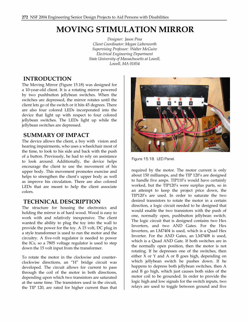
INTRODUCTION The Moving Mirror (Figure 15.18) was designed for a 10-year-old client. It is a rotating mirror powered by two pushbutton jellybean switches. When the switches are depressed, the mirror rotates until the client lets go of the switch or it hits 45 degrees. There are also four colored LEDs incorporated into the device that light up with respect to four colored jellybean switches. The LEDs light up while the jellybean switches are depressed.
SUMMARY OF IMPACT The device allows the client, a boy with vision and hearing impairments, who uses a wheelchair most of the time, to look to his side and back with the push of a button. Previously, he had to rely on assistance to look around. Additionally, the device helps encourage the client to use the movement of his upper body. This movement promotes exercise and helps to strengthen the client’s upper body as well as improve his circulation. There are also colored LEDs that are meant to help the client associate colors.
TECHNICAL DESCRIPTION The structure for housing the electronics and holding the mirror is of hard wood. Wood is easy to work with and relatively inexpensive. The client wanted the ability to plug the toy into the wall to provide the power for the toy. A 15 volt, DC plug in a style transformer is used to run the motor and the circuitry. A five-volt regulator is needed to power the ICs, so a 7805 voltage regulator is used to step down the 15 volt input from the transformer.
To rotate the motor in the clockwise and counter-clockwise directions, an “H” bridge circuit was developed. The circuit allows for current to pass through the coil of the motor in both directions, depending upon which two transistors are saturated at the same time. The transistors used in the circuit, the TIP 120, are rated for higher current than that
required by the motor. The motor current is only about 150 milliamps, and the TIP 120’s are designed to handle five amps. TIP110’s would have certainly worked, but the TIP120’s were surplus parts, so in an attempt to keep the project price down, the TIP120’s are used. In order to saturate the two desired transistors to rotate the motor in a certain direction, a logic circuit needed to be designed that would enable the two transistors with the push of one, normally open, pushbutton jellybean switch. The logic circuit that is designed contains two Hex Inverters, and two AND Gates. For the Hex Inverters, an LM7404 is used, which is a Quad Hex Inverter. For the AND Gates, an LM7408 is used, which is a Quad AND Gate. If both switches are in the normally open position, then the motor is not rotating. If he depresses one of the switches, then either X or Y and A or B goes high, depending on which jellybean switch he pushes down. If he happens to depress both jellybean switches, then A and B go high, which just causes both sides of the motor coil to be grounded. In order to provide the logic high and low signals for the switch inputs, two relays are used to toggle between ground and five
Figure 15.18. LED Panel.

Chapter 14: University of Massachusetts Lowell 273
volts from the regulator. Ground, which is zero volts, is a logic low signal, and the five volts from the regulator is a logic high signal. This is done so that when the two motor switches are in the normally open state, then the two relays provide low signals to both the A and B inputs, keeping the motor from rotating in either direction. The outputs from the logic circuit are connected to opto couplers, which are 4N27’s. An opto isolator uses an infrared LED that can be powered with as little as 20
milliamps, so the transistors will conduct when the output of the logic circuit is high. When the transistors are active, they pull the 15 volts down from the supply and 10K ohm resistors provide the 1.5 milliamps to the TIP 120’s that is necessary for saturation. The final product can be seen in Figure 15.19 below.
The cost of parts/material is approximately $320.
Figure 15.19. Final Product.

274 NSF 2004 Engineering Senior Design Projects to Aid Persons with Disabilities
VOICE CONTROLLED WHEELCHAIR WITH OBSTACLE AND DROP-OFF DETECTION
Designer: Jeffrey J. Sawyer Supervising Professor: Walter McGuire
Electrical and Computer Engineering Department University of Massachusetts at Lowell
Lowell, MA 01854
INTRODUCTION The voice controlled wheelchair with obstacle detection and avoidance (VCWODA) is designed to allow an individual with quadriplegia the ability to control an electric wheelchair by voice. The VCWODA has collision and drop-off detection, which gives it the ability to be able to detect and avoid obstacles and drop-offs (stairs, curbs, etc.) in its direction of motion; this ability provides additional safety to the user. The goal of the project is to allow the user the freedom from the use of a sip and puff interface or a head switch interface, which can be uncomfortable, while adding new safety features to an existing electric wheelchair.
SUMMARY OF IMPACT The project will enhance the lives of individuals with quadriplegia by allowing them the freedom from using any external devices that may be uncomfortable or awkward to use. The project is easy to operate and safe.
TECHNICAL DESCRIPTION The purpose of the VCWODA with obstacle detection and avoidance is to allow individuals who are unable to operate an electric wheelchair through the use of a joystick an optional mode of operation. The voice recognition system allows the user the ability to control an electric wheelchair through the connection to its onboard digital interface. The voice recognition system is made from the Sensory, Inc. Voice Extreme™ Module and it is programmed to be speaker dependent; it is trained prior on the first use. After the first use, the user’s data are stored in memory and there is no need for additional training. The microphone used for the voice recognition is a throat microphone that attaches around the user’s neck; the microphone is unaffected by outside noise. The commands used in the VCWODA allow the user the ability to control to varying degrees the wheelchair’s forward and
reverse motion along with the left and right motion too. All the timing of the wheelchair’s movement has been tested on an Invacare Ranger X wheelchair. Note that if a movement command is given and it is given again before its movement time ends, it will reset the movement time to its first value. For example if the user says “forward” and then waits 30 seconds and says it again, the time until the wheelchair stops will be reset to 35 seconds. Other commands used allow the user the ability to navigate through the verbal menus programmed into the voice recognition system. A listing of the voice commands recognized is given below.
• Forward - Move forward for 35 seconds
• Reverse - Move in reverse for 10 seconds
• Ar - Turn right for 0.4 seconds if the wheelchair is stopped or 0.175 seconds if the wheelchair is moving forward
• El - Turn left for 0.4 seconds if the wheelchair is stopped or 0.175 seconds if the wheelchair is moving forward.
• Right - Turn right for one second if the wheelchair is stopped or 0.3 seconds if the wheelchair is moving forward
• Left - Turn left for one second if the wheelchair is stopped or 0.3 seconds if the wheelchair is moving forward
• Hard Right - Turn right for two seconds if the wheelchair is stopped or 0.7 seconds if the wheelchair is moving forward
• Hard Left - Turn left for two seconds if the wheelchair is stopped or 0.7 seconds if the wheelchair is moving forward

Chapter 14: University of Massachusetts Lowell 275
• Faster - Only active while the wheelchair is moving forward. Increases the speed of the wheelchair if it is below its greatest speed
• Slower - Only active while the wheelchair is moving forward. Decreases the speed of the wheelchair if it is above its slowest speed
• Go - Move forward for 1.2 seconds with no sensor interruption
• Back - Move in reverse for 1.2 seconds with no sensor interruption
• Go To Sleep - Change the mode from listening mode to sleep mode, the wheelchair must be stopped first
• Wake Up - Change the mode from sleep mode to listening mode
• Main Menu - Change the mode from either sleep mode or listening mode to main menu mode
• Stop - Stop the wheelchair from moving
• No - Only active when the system asks “Are you Sure?”, causes the AreYouSure function to return false
• Yes - Only active when the system asks “Are you Sure?”, causes the AreYouSure function to return true
• One - Only active in the main menu, used to select menu selection one
• Two - Only active in the main menu, used to select menu selection two
• Three - Only active in the main menu, used to select menu selection three
• Four - Only active in the main menu, used to select menu selection four
The sensor control system uses a Basic Stamp 2 to control a combination of infrared and sonar sensors used to detect obstacles around the wheelchair as well as the lack of ground in the front and rear of the wheelchair as when the wheelchair comes close to a curb or a set of stairs. The two sonar sensors used on the VCW are mounted on the front and rear of the wheelchair. The front sonar sensor is programmed to detect two different ranges. The first range is 80 inches and will cause the wheelchair to slow to the lowest speed. The second range is 45 inches and will cause the wheelchair to stop. The rear sonar sensor is programmed to detect at one range of 40 inches and will also cause the wheelchair to stop. The infrared sensors on the wheelchair are used to detect the ground in the front and rear of the wheelchair, if they do not detect the ground in the front or rear of the wheelchair while they are moving in the direction of the sensor they will also cause the wheelchair to stop. The last of the infrared sensors are used on the left and right of the wheelchair to detect objects to the left or right of the wheelchair. If the sensor detects an object to the left of the wheelchair while moving forward, the chair will automatically adjust the movement of the wheelchair to the right until it no longer detects the object and vice versa for the right sensor. If both left and right sensors detect an object at the same time the wheelchair will stop.
The sensor control system and the voice recognition system are programmed to communicate with each other through the use of a simple two-bit op-code. The information that is transmitted from the voice recognition system to the sensor control system is whether the voice recognition system is in forward, reverse, or neutral mode. The information that is transmitted from the sensor control system to the voice recognition system is the ready, slow down, or stop command.
The cost of parts for the voice recognition and sensor control system is $350.

276 NSF 2004 Engineering Senior Design Projects to Aid Persons with Disabilities
FIVE-SOUND RECORDER FOR INTERACTIVE STORY READING
Designer: John A. Alfeo Client Coordinator: Bonnie Paulino Lanen, Kennedy Day School, Brighton, MA
Supervising Professor: Alan Rux Electrical and Computer Engineering Department
University of Massachusetts Lowell Lowell, MA 01854
INTRODUCTION The five sample voice recorder is designed to accommodate stories with sounds that are read to children who have multiple disabilities. The main purpose of the device is to make listening to stories more fun and enjoyable. The device can record five separate sound effects and be played back one sound at a time. Upon completion, the five sample sound recorder was presented to a school for children with cognitive and physical disabilities. The ages range from small children to 21 years of age.
SUMMARY OF IMPACT The design criteria for the five sample sound recorder were defined by the school librarian. She requested a device that could record multiple sounds that could be played back one after another. She asked that it be simple to use and require little or no maintenance.
TECHNICAL DESCRIPTION The device consists of three main components: 1) record playback chip, 2) microcontroller, and 3) audio amplifier. The playback record chip is an ISD2560 and can record up to 60 seconds of audio. The microcontroller used is the Basic Stamp 2. It has 20 I/O pins and a voltage regulator with an output voltage of five volts. The LM386 audio amplifier is used to produce sufficient audio sound levels.
The ISD2560 is a 28-pin record playback chip. It has an input sample rate of 8kHz, which is sufficient to output clear undistorted sound. The chip is completely controlled by the microcontroller. The audio output of the chip is limited to only 50mW. Because the device must be able to fill a small room with a sound, the LM386 audio amplifier is used. The amplifier can output 1.25W of sound with a total harmonic distortion of 10 percent. This high
gain is achieved by installing a 10μ F capacitor at the two gain pins of the amplifier. The audio level can be controlled by a 100 kΩ potentiometer installed in parallel with the audio inputs of the amplifier.
To record messages, an electret microphone is used. It requires external circuitry because it cannot produce a current flow or a potential to be developed from sound wave pressure. The manufacturer of the ISD2560 provides a circuit that will produce a dc bias for the microphone to work properly. The circuit consists of seven components. Two .1μ F capacitors are used for blocking dc and are connecting to the microphone and microphone reference pins and a 22μ F capacitor is used for filtering. Two 10 kΩ resistors are used for common mode rejection of the microphone preamplifier.
The microcontroller is used to power the ISD2560, as well as provide the proper addressing for record and playback. It is programmed using the PBasic programming language. Five pushbutton switches are connected to five pins of the microcontroller. When one of the five buttons is pressed, it sends an active low signal to the pin. When this occurs the program distinguishes which button has been pressed and sends the proper address to the ISD2560. At the same time, the chip enable turns active low, which activates the ISD2560, and the previously recorded sound in the corresponding space in memory is played.
To power the circuit, a 9.6V 1aH rechargeable NiCd battery is used. Due to the relatively high amperage rating, the device can be used multiple times before the battery needs to be recharged.
The cost of parts and material is approximately $150.

Chapter 14: University of Massachusetts Lowell 277
Figure 15.20. Five Sample Sound Recorder.
278 NSF 2004 Engineering Senior Design Projects to Aid Persons with Disabilities
INDOOR NAVIGATION DEVICE FOR A PERSON WITH VISUAL IMPAIRMENT
Designers: Yichi Au, Ting Jen, John Wong Client Coordinator: Dana Bernor, Lowell, MA
Supervising Professor: Walter McGuire Electrical and Computer Engineering Department
One University Avenue Lowell, MA 01854
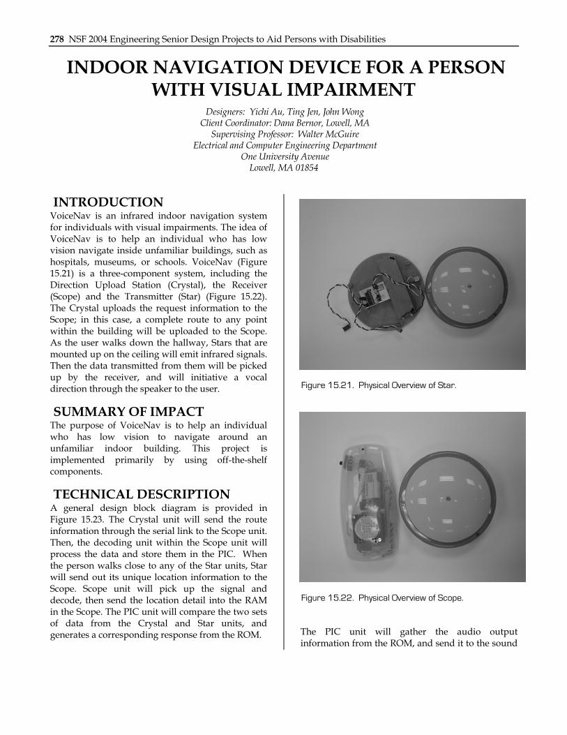
INTRODUCTION VoiceNav is an infrared indoor navigation system for individuals with visual impairments. The idea of VoiceNav is to help an individual who has low vision navigate inside unfamiliar buildings, such as hospitals, museums, or schools. VoiceNav (Figure 15.21) is a three-component system, including the Direction Upload Station (Crystal), the Receiver (Scope) and the Transmitter (Star) (Figure 15.22). The Crystal uploads the request information to the Scope; in this case, a complete route to any point within the building will be uploaded to the Scope. As the user walks down the hallway, Stars that are mounted up on the ceiling will emit infrared signals. Then the data transmitted from them will be picked up by the receiver, and will initiative a vocal direction through the speaker to the user.
SUMMARY OF IMPACT The purpose of VoiceNav is to help an individual who has low vision to navigate around an unfamiliar indoor building. This project is implemented primarily by using off-the-shelf components.
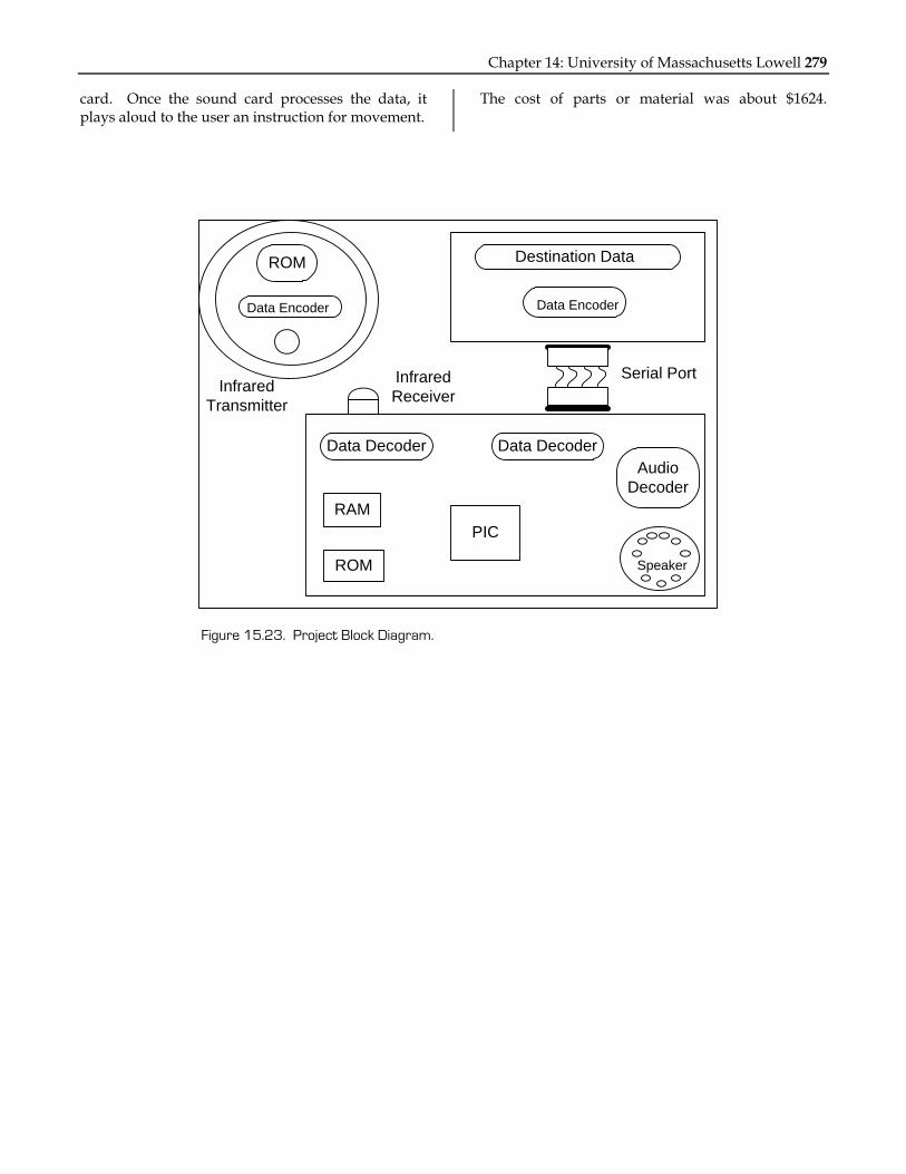
TECHNICAL DESCRIPTION A general design block diagram is provided in Figure 15.23. The Crystal unit will send the route information through the serial link to the Scope unit. Then, the decoding unit within the Scope unit will process the data and store them in the PIC. When the person walks close to any of the Star units, Star will send out its unique location information to the Scope. Scope unit will pick up the signal and decode, then send the location detail into the RAM in the Scope. The PIC unit will compare the two sets of data from the Crystal and Star units, and generates a corresponding response from the ROM. The PIC unit will gather the audio output
information from the ROM, and send it to the sound
Figure 15.21. Physical Overview of Star.
Figure 15.22. Physical Overview of Scope.
Chapter 14: University of Massachusetts Lowell 279
card. Once the sound card processes the data, it plays aloud to the user an instruction for movement.
The cost of parts or material was about $1624.
ROM
Data Encoder
Destination Data
Data Encoder
Serial PortInfrared
Transmitter
Data Decoder Data Decoder
RAM
ROM
PIC
Audio Decoder
Speaker
Infrared Receiver
Figure 15.23. Project Block Diagram.
280 NSF 2004 Engineering Senior Design Projects to Aid Persons with Disabilities
ENLARGED TELEPHONE KEYPAD Designer: Krishna Upadhyay
Client Coordinator: Ms. Kathy Finnigan, Kennedy Day School, Brighton, MA Supervising Professor: Walter McGuire
Electrical and Computer Engineering Department University of Massachusetts at Lowell,
Lowell, MA
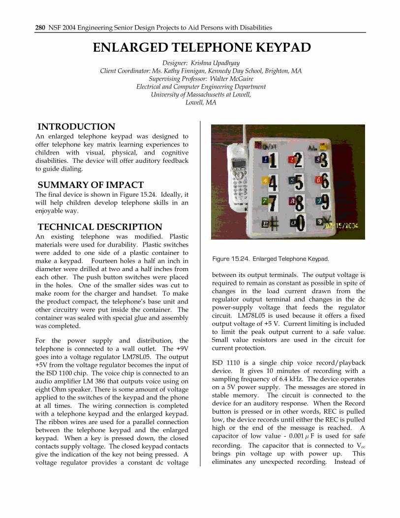
INTRODUCTION An enlarged telephone keypad was designed to offer telephone key matrix learning experiences to children with visual, physical, and cognitive disabilities. The device will offer auditory feedback to guide dialing.
SUMMARY OF IMPACT The final device is shown in Figure 15.24. Ideally, it will help children develop telephone skills in an enjoyable way.
TECHNICAL DESCRIPTION An existing telephone was modified. Plastic materials were used for durability. Plastic switches were added to one side of a plastic container to make a keypad. Fourteen holes a half an inch in diameter were drilled at two and a half inches from each other. The push button switches were placed in the holes. One of the smaller sides was cut to make room for the charger and handset. To make the product compact, the telephone’s base unit and other circuitry were put inside the container. The container was sealed with special glue and assembly was completed.
For the power supply and distribution, the telephone is connected to a wall outlet. The +9V goes into a voltage regulator LM78L05. The output +5V from the voltage regulator becomes the input of the ISD 1100 chip. The voice chip is connected to an audio amplifier LM 386 that outputs voice using on eight Ohm speaker. There is some amount of voltage applied to the switches of the keypad and the phone at all times. The wiring connection is completed with a telephone keypad and the enlarged keypad. The ribbon wires are used for a parallel connection between the telephone keypad and the enlarged keypad. When a key is pressed down, the closed contacts supply voltage. The closed keypad contacts give the indication of the key not being pressed. A voltage regulator provides a constant dc voltage
between its output terminals. The output voltage is required to remain as constant as possible in spite of changes in the load current drawn from the regulator output terminal and changes in the dc power-supply voltage that feeds the regulator circuit. LM78L05 is used because it offers a fixed output voltage of +5 V. Current limiting is included to limit the peak output current to a safe value. Small value resistors are used in the circuit for current protection.
ISD 1110 is a single chip voice record/playback device. It gives 10 minutes of recording with a sampling frequency of 6.4 kHz. The device operates on a 5V power supply. The messages are stored in stable memory. The circuit is connected to the device for an auditory response. When the Record button is pressed or in other words, REC is pulled low, the device records until either the REC is pulled high or the end of the message is reached. A capacitor of low value - 0.001μ F is used for safe recording. The capacitor that is connected to Vcc brings pin voltage up with power up. This eliminates any unexpected recording. Instead of
Figure 15.24. Enlarged Telephone Keypad.

Chapter 14: University of Massachusetts Lowell 281
using edge-activated playback, level-activated playback has been used so that, when the PLAYL is pulled low, the playback cycle begins. As soon as PLAYL is pulled high, the playback stops right away. The device has a pull-up resistor of about 100 kΩ that pulls the voltage to Vcc. RECLED has output low when recording to the device. An LED signals by lighting up the record cycle in progress. SP+ and SP- provide direct drive for loud speakers with an impedance of 8Ω .
A LM386 power audio amplifier is used. Usually, the gain is set internally to 20 in this 8 pin DIP.
However, by adding an additional capacitor of value 10μ F between pins one and eight increases the gain to 200. This capacitor bypasses the 1.35 kΩ internal resistor and makes the amplifier more resourceful. The device takes +5 V DC as supply. Given that the LM386 is used with higher gains, it is necessary to bypass the unused input to prevent reduction of gain and instabilities.
The cost of parts/material is approximately $181.
Figure 15.25. Inside View of Phone.

282 NSF 2004 Engineering Senior Design Projects to Aid Persons with Disabilities
POURING CUP Designer: Mher Ketchedjian
Client Coordinator: Special Education Department, Lowell High, Lowell, MA Supervising Instructor: Mr. Jay Fu
Department of Electrical and Computer Engineering University of Massachusetts-Lowell
Lowell, MA 01854
INTRODUCTION The Pouring Cup is a special tool that allows anyone to pour virtually any substance into another cup or bowl (Figure 15.26). It could be used to pour substances such as liquids, sand or flour. It is switch activated, and it tilts when activated and returns back to the original position with a reversing switch. The Pouring Cup consists of both mechanical and electrical parts. Since many individuals with disabilities have a difficult time moving their wrists or hands it will be useful for pouring and learning the measurements from the tilting cup. The project is for the special education department at a high school. This is also a risk-free tool because it does not use AC power.
SUMMARY OF IMPACT Measuring substances will help students learn more about measurements and volumes that are used for cooking or baking. The cup is wired to a joystick with two switches: one for the activation of the motor and the other for the direction, to tilt the cup down (counterclockwise) and tilt the cup back up (clockwise). The cup has measuring lines. The project will be placed on a kitchen countertop. It will be used by the students with the help of their instructors.
TECHNICAL DESCRIPTION A 5- by 8-inch wooden box includes the motor, wiring, circuit, and a battery pack on the back side. It has a 9- by 11-inch wooden base on which the box rests. Transparent epoxy glass is mounted on the facade of the main box, in a color that matches the paint on the wood. The wooden area is nailed together while epoxy glass is mounted with a screw. The motor is powered by a 7.4V DC electric power with a gearbox. The gearbox on the motor is to control the speed of the motor slowly and produce higher torque than what the motor is already powered. Speed control and safety are the main reasons why a DC motor is chosen over an AC
motor. The circuit is powered by 6V DC that is four alkaline 1.5V batteries going to the chip and two pairs of transistors. The four transistors are used to control the motor in both directions. They are wired along with two capacitors, two resistors and two diodes. The transistors receive the impulses that are sent by the 555 timer and uses that impulse to time the turns of the motor. A 555 timer chip is implemented in order to create the Pulse Width Modulator. This chip is used to approximate a low frequency modulating signal that produces a square waveform which is proportional to the input voltage. Since the design concerns low voltages, the 555 timer is chosen because it has an operating voltage at 1.5 volts. The output signal is determined by the operating state of the MOSFET switch. The frequency in which the timer is outputted depends on the values of the resistors and capacitors. VCC is the input voltage supplied by the output of the charge motor. The output voltage of the circuit is sent to the gate of the MOSFET. Depending on the value of the threshold voltage, therefore, the transistor turns on and the switch is closed. When the switch is closed, current flows through the circuit; otherwise, the transistor is off, resulting in an
Figure 15.26. Pouring Cup.

Chapter 14: University of Massachusetts Lowell 283
open switch. Pin 5 is the control voltage, dependent on the duty cycle when a high or low signal is inputted.
The cost of parts is approximately $120.

284 NSF 2004 Engineering Senior Design Projects to Aid Persons with Disabilities
SENSITIVE CANE Designers: Mohammad Ali Shah
Client Coordinator: Yuka, Boston Homes, Boston, MA Supervising Professor: Jay Fu
Electrical and Computer Engineering Department University of Massachusetts, Lowell
Lowell, MA 01854
INTRODUCTION A cane was designed to be able to sense certain distances to surrounding surfaces and thereby alert a user of obstacles. The design involved the use of infrared sensors and an OOPIC microcontroller integrated into the cane.
SUMMARY OF IMPACT Although the project was a success, there was still room for improvement. Given that the weight of the cane is concentrated toward the bottom, it was difficult to carry for an extended period of time. A counterbalance was added in the project to help lessen the strain. Another improvement that could have been made involves expanded programming with a reduction in complex circuitry and hardware.
TECHNICAL DESCRIPTION The product has been designed to be user friendly. To activate the cane, there is a simple on/off switch located on the attached box. Once activated, a user
holds the handle and then slightly swings the cane back and forth in front of him or her to trigger the infrared sensors. A user will know when an obstacle is approaching, and the type of obstruction they are confronting, because they will hear a buzzing sound from the box that varies with changes in depth. A louder beep in the front of the handle signifies that an object has come within less than one and a half feet of the user; a single beep signifies that an object has come within one and a half to three feet of the user. In the event that the power source fails, the battery can be replaced with a new nine-volt battery located inside of the box on the front of the cane.
The cost of parts and material was approximately $120.

Chapter 14: University of Massachusetts Lowell 285
Figure 15.27. Sensitive Cane.
Figure 15.28. Cane Sensor Mechanism.
286 NSF 2004 Engineering Senior Design Projects to Aid Persons with Disabilities
VOICE ACTIVATED BUBBLE Designer: Mohammed Aman
Client Coordinator: Bonnie Paulino, Kennedy Day School Department of Electrical and Computer Engineering
University of Massachusetts Lowell Lowell, MA 01854
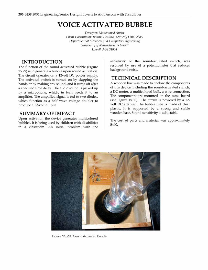
INTRODUCTION The function of the sound activated bubble (Figure 15.29) is to generate a bubble upon sound activation. The circuit operates on a 12volt DC power supply. The activated switch is turned on by clapping the hands or by making any sound, and it turns off after a specified time delay. The audio sound is picked up by a microphone, which, in turn, feeds it to an amplifier. The amplified signal is fed to two diodes, which function as a half wave voltage doubler to produce a 12-volt output.
SUMMARY OF IMPACT Upon activation the device generates multicolored bubbles. It is being used by children with disabilities in a classroom. An initial problem with the
sensitivity of the sound-activated switch, was resolved by use of a potentiometer that reduces background noise.
TECHNICAL DESCRIPTION A wooden box was made to enclose the components of this device, including the sound-activated switch, a DC motor, a multicolored bulb, a wire connection. The components are mounted on the same board (see Figure 15.30). The circuit is powered by a 12-volt DC adapter. The bubble tube is made of clear plastic. It is supported by a strong and stable wooden base. Sound sensitivity is adjustable.
The cost of parts and material was approximately $400.
Figure 15.29. Sound Activated Bubble.

Chapter 14: University of Massachusetts Lowell 287
Figure 15.30. Voice Activated Bubble.

288 NSF 2004 Engineering Senior Design Projects to Aid Persons with Disabilities
VOICE-ACTIVATED ENVIRONMENTAL CONTROL SYSTEMS Designer: Monika Patel
Client: Cindy Tatelman from commission of Disabilities Supervisor of the Project: Mr. McGuire, Walter
University of Massachusetts at Lowell Department of Electrical and Computer Engineering
Universities of Massachusetts, One University Ave. Lowell, M.A.01854
INTRODUCTION The Environmental Control System was built for an individual who has limited mobility. She uses a wheelchair and needs assistance for controlling environmental devices and appliances, such as lights or fans. This project provides the client with the ability to control multiple electrical devices without assistance.
SUMMARY IMPACT This project is controlled with speech output that allows the user to operate (hands-free) electrical appliances, including light switches, lamps, radios, televisions, fans, stereo systems, and kitchen appliances. The system uses voice command to control multiple televisions, numerous lights, a telephone, an automatic door and various other appliances.
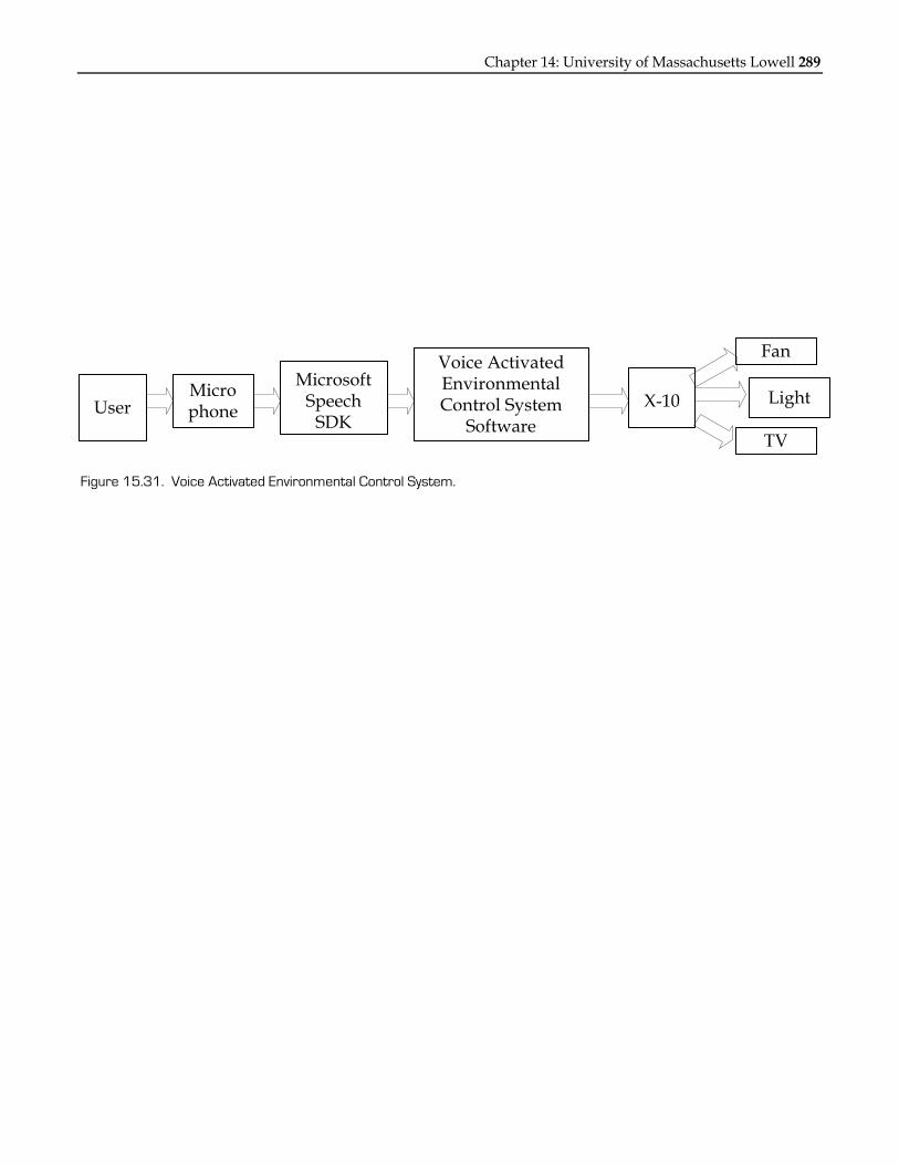
TECHNICAL DESCRIPTION The project consists of two parts: software and hardware. The hardware portion consists of an X-10 transceiver, and the software portion consists of two Microsoft programs: Visual Basic and Microsoft Speech SDK 5.1. Microsoft Speech SDK 5.1 consists of a voice recognition system that allows spoken words, letters and phrases to serve as an input to the computer. When the system receives an utterance that it recognizes, it initiates a computer function, such as “LIGHT ON,” created in Visual Basic code. This function sends signals to the serial port through the X-10 to run all electrical appliances that are
connected to the X-10 module. Figure 15.31 presents a flow-chart.
Hardware Description: One X-10 transceiver is connected to the computer via a parallel port, which transmits wireless signals to all X-10 appliance modules, which are plugged into a standard wall outlet. Each X-10 module must be connected with an electrical device.
Software Description: The Voice-Activated Environmental Control System Software takes input from a microphone. Using speech recognition technology, it finds the text input corresponding to the voice input. After finding the appropriate operation, it displays the command on the screen and sends a signal to the X-10 Active Home kit to perform the operation. Microsoft Speech SDK 5.1 is used to implement speech recognition technology. Microsoft Visual Basic 6 is used to create user friendly GUI as well as programming functionality. Visual basic code is written for each command, such as “ON,” “START,” “STOP,” “OFF” and others. The user trains the speech recognition system.
The total cost of parts and labor was approximately $4600.
Chapter 14: University of Massachusetts Lowell 289
UserMicrophone
Microsoft Speech
SDK
Voice Activated Environmental Control System
SoftwareX-10
Fan
Light
TV
Figure 15.31. Voice Activated Environmental Control System.
290 NSF 2004 Engineering Senior Design Projects to Aid Persons with Disabilities
SWITCH-ACTIVATED TALKING CLOCK AND CALENDAR
Designer: Nitin Goyal Client: Lowell High School, Lowell MA Supervising Professor: Walter McGuire
Department of Electrical and Computer Engineering University of Massachusetts at Lowell
Lowell, MA 01851
INTRODUCTION A switch-activated talking clock and calendar was designed to provide assistance to individuals with visual impairments. The project is a portable device that can be easily carried. It has two switches: one for time output and one for date output.
SUMMARY OF IMPACT The design requirements for the talking clock were defined by the supervisor of a center for children with disabilities. The object of the project was to foster time telling and cause and effect learning for children who are visually impaired.
TECHNICAL DESCRIPTION The project was made of a plastic case 3.5 inches in length, 2.5 inches in width and 2 inches in height. Overall, the project (Figure 15.32) used only three chips: one PIC16F84A microprocessor, one 2560 ISD
chip and one LM386 audio amplifier. The microprocessor was programmed to address an ISD chip in M0 mode and was also programmed for the regular clock function. A total of 58 commands were stored in the ISD for calendar and time output. A 4 MHz crystal was used for the PIC because, using this crystal, it takes the microprocessor 1 μ s to compile one line of command. Four AA batteries were used as a power supply.
The program was written in a way that it checks the switches and updates the second, minute, hour, day, and month in every loop. Two switches were used: one for the calendar and one for the time output. If any switch was pressed, it took two seconds for the time or calendar output. Time was added into the regular clock cycle to maintain accuracy. Final accuracy of the project was approximately 95%.
Final cost of the project was $30.

Chapter 14: University of Massachusetts Lowell 291
Figure 15.32. Final Circuit Design.

292 NSF 2004 Engineering Senior Design Projects to Aid Persons with Disabilities
COLOR RECOGNITION TOY Designers: Parth Patel
Client Coordinator: Lowell High School Supervising Professor: Jay Fu
College of Engineering Department of Electrical Engineering
1 University Ave Lowell, MA 01854
INTRODUCTION The goal of this project was to create a toy that would help give audio and visual stimulation to children with cognitive and motor disabilities at a high school. The toy must also be durable, flexible, and simple.
SUMMARY OF IMPACT This device provides audio and visual stimulation to children with disabilities.
TECHNICAL DESCRIPTION A Stamp Chip is programmed to send inputs and outputs to different components. The first two randomly assign three different LEDs to be lit up for each pushbutton. There are six permutations of LED lighting orders. The random number generator takes a seed number, which is originally defined by the programmer, and creates a random number. This number is used to determine which of the six cases it will match. Once this case is set, the program uses another seed number from the variable YNUM to create a new second random number. This random number is used to determine which of the colors is selected. These selected colors
are put into three cases under the six original cases. This makes a possible 18 combinations for the student to play with. Once the desired color is selected, the Basic Stamp chip outputs 10 signals to the ISD2590.
The color is then played through a speaker. For each case a color is selected. That color corresponds to a certain pushbutton. The program then loops until the correct pushbutton is pushed. If an incorrect answer is pressed, the program loops back and repeats the desired color through the ISD2590. If a correct answer is selected then the program falls out of the loop and goes to a Correct function. The Correct function turns off all of the lights, then randomly picks a third number. The Correct function also increments the three random variables. This produces a new seed number for the next time the program is run. This third random number is used to determine a random song to play using the ISD2590.
The cost of parts and material is approximately $203.

Chapter 14: University of Massachusetts Lowell 293
Figure 15.33. Color Recognition Toy.

294 NSF 2004 Engineering Senior Design Projects to Aid Persons with Disabilities
MOTORIZED STANDER Designers: Philip L. Sliney II (in conjunction with my partner John P. Thomas IV)
Supervising Professor: Walter McGuire Electrical and Computer Engineering Department
University of Massachusetts at Lowell, Lowell, MA 01854
INTRODUCTION The motorized stander is designed to allow children with multiple physical and cognitive disabilities to easily move around while standing upright. This device is similar to a motorized wheelchair in nature, but the user is held in an upright position instead of sitting down. The motorized stander allows the user to be held in an upright position, which may help with improved posturing and also promote more equalized height when interacting with others.
SUMMARY OF IMPACT Multiple tests were carried out throughout the design and construction phases to demonstrate the safety and reliability of this project. Another important criterion was modularity. This project had to be easy to fix in the future, and also it had to be easy to add future attachments if necessary.
TECHNICAL DESCRIPTION The project had a foldable design for easy disassembly and transport. It incorporated a unique suspension system that allowed all six wheels to be
in constant contact with the ground at all times, allowing the motorized stander to have no problem navigating over door frames and elevator thresholds.
A design for control of the motors using PWM was constructed and tested. This design incorporated 14 potentiometers for various adjustments, including turning radius and speed, acceleration rate, deceleration rate, maximum speed, FET saturation level, and etc.
The motorized stander project has been thoroughly tested and reviewed by a number of people. It has been used by a child with a cognitive disability, as well as other children from ages nine to 14 and some adults.
All moving parts and all wires were covered to help prevent safety hazards. An impact-absorbent bumper system was conceived and incorporated into the final project to reduce potential safety problems. Impact tests yielded positive results.
The cost of parts/material was approximately $1000.

Chapter 14: University of Massachusetts Lowell 295
Figure 15.34. Original Manual Stander.
Figure 15.35. Motorized Stander Prototype.
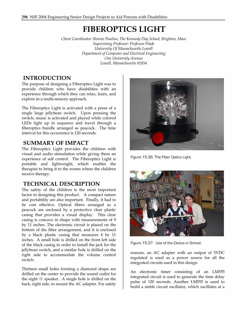
296 NSF 2004 Engineering Senior Design Projects to Aid Persons with Disabilities
FIBEROPTICS LIGHT Client Coordinator: Bonnie Paulino, The Kennedy Day School, Brighton, Mass
Supervising Professor: Professor Wade University Of Massachusetts Lowell
Department of Computer and Electrical Engineering One University Avenue
Lowell, Massachusetts 01854
INTRODUCTION The purpose of designing a Fiberoptics Light was to provide children who have disabilities with an experience through which they can relax, learn, and explore in a multi-sensory approach.
The Fiberoptics Light is activated with a press of a single large jellybean switch. Upon pressing the switch, music is activated and played while colored LEDs light up in sequence and travel through a fiberoptics bundle arranged as peacock. The time interval for this occurrence is 120 seconds.
SUMMARY OF IMPACT The Fiberoptics Light provides the children with visual and audio stimulation while giving them an experience of self control. The Fiberoptics Light is portable and lightweight, which enables the therapist to bring it to the rooms where the children receive therapy.
TECHNICAL DESCRIPTION The safety of the children is the most important factor in designing this product. A compact nature and portability are also important. Finally, it had to be cost effective. Optical fibers arranged as a peacock are enclosed by a protective clear plastic casing that provides a visual display. This clear casing is concave in shape with measurements of 9 by 11 inches. The electronic circuit is placed on the bottom of the fiber arrangement, and it is enclosed by a black plastic casing that measures 4 by 11 inches. A small hole is drilled on the front left side of the black casing in order to install the jack for the jellybean switch, and a similar hole is drilled on the right side to accommodate the volume control switch.
Thirteen small holes forming a diamond shape are drilled on the center to provide the sound outlet for the eight Ω speaker. A single hole is drilled on the back, right side, to mount the AC adapter. For safety
reasons, an AC adapter with an output of 5VDC regulated is used as a power source for all the integrated circuits used in this design.
An electronic timer consisting of an LM555 integrated circuit is used to generate the time delay pulse of 120 seconds. Another LM555 is used to build a stable circuit oscillator, which oscillates at a
Figure 15.36. The Fiber Optics Light.
Figure 15.37. Use of the Device in School.

Chapter 14: University of Massachusetts Lowell 297
frequency of 63 HZ. The frequency of this oscillator determines the speed with which the LED chaser lights up in a sequential manner. The CD4017 decade counter/decoder is used to build the light chaser. The LEDs used in this design have to provide 10 candella, 7000 mcd and wavelengths of 530nm, due to the fact that the light emitted has to
travel through the fiber optics bundle and still provide high luminosity at the output. Finally, the ISD25120 with sampling rate of 4.0 kHz is used to store a children’s song with duration of 120 seconds.
The cost of parts and material is approximately $160.
Date: April 15, 2004
Title
Fiber Optics Light Schematic
Size A Document Name
Rejane Smith
Sheet 1 of 1
+5 V
ON/OFF
S1
R6
100k
+5 V
+5 V
+5 V
+5 V
+5 V
100k 100k
R3R1 R2
C1
0.1 u
A2
A1
20M
C3C2
4.7 u0.1 u
+5 V C4
R4 1.0 k R5
0.1 u
4.7 k
1 2 3 4
8 7 6 5
LM555
ISD25120
A0A1A2A3A4A5A6A7A8A9
CEPDP/RCLK
VCCDVCCA
VSSDVSSA
S P+S P-
ANA_IN
ANA_OUT
MIC_REFMIC
AGC
C9
R9 5.1 k
C7 C8
0.1 u 0.1 u
0.1 u
R12
10kMicrophone
MP
R10
C6
220u
R8
470k
C5
4.7u1k
R1110k
A4
R7 200 ohm
119651107423
1614
158
13
CD4017A3
1 2 3 4
8 7 6 5
LM555
To Fiber Optics
D1TOD10
C13 4.7u
R13
10k
A5
2
36 1 8
6
4 7 LM386
C16 470 u
C1410 u C15
47u
R14
1k
SP1
8 OhmSpeakerC17
0.1 u
C10 C11 C12
0.1 u 0.1 u 22u
12345678910
2816
1213
141520
21
1817
19
Figure 15.38. Schematic Diagram.

298 NSF 2004 Engineering Senior Design Projects to Aid Persons with Disabilities
VIDEO SWITCH TO FACILITATE MONITORING OF A CHILD
Designer: Richard Nedder Supervising Professors: David Wade and Walter McGuire
Department of Electrical and Computer Engineering University of Massachusetts Lowell,
Lowell, MA 01854
INTRODUCTION The Video Switch is designed to facilitate the monitoring of a child for a person with multiple disabilities. This device is an infrared controlled video switch that allows switching between video signals to monitor an apartment. By pressing a button on a remote control, different views of the apartment can be seen. Once completed, the project was installed for a client unable to monitor his child during certain times of the day. The goal of this project is to provide a way for the client to monitor his son as well as other individuals entering the apartment building.
SUMMARY OF IMPACT The range of movement of the client limited the design and control of the switch. From early evening to mid-morning, the client was located in one spot in his apartment and could not check on the status of his child. By having an infrared controlled video switch, he is able to check, from his location, the entire apartment and also the front door. This keeps him from having to try to shout to locate the child’s location and status.
TECHNICAL DESCRIPTION The main part of the system is located in a small eight by five by three-inch plastic case. Inside, two small printed circuit boards are mounted to the bottom cover of the case (Figure 15.39). The input and output jacks for the audio and video are mounted on the side of the case. The power jack is mounted on the side and allows access to a wall-mounted transformer for power. Also on the side of the case is a pushbutton switch that allows the source to be manually changed in the event that the infrared control fails.
The infrared signals are received on a PCM Photo Module, and then fed to an infrared decoder. The infrared decoder is chosen for its compatibility with Sony Television remote control codes. The control is set up to accept channel up and down, volume up and down, and channel buttons zero through nine. All of these buttons operate the same output to make changing the source an easy task. A small digital logic circuit consisting of some OR gates and some J-K Flip Flops create the input that the video and audio switching circuitry uses. The video and audio switching is facilitated via two multiplexers. Both multiplexers have built in decoders. This makes it easy to scroll easily sequentially through the four video feeds. The video multiplexer is selected has a built-in amplifier, good off channel isolation and ease of installation and use. The audio multiplexer is chosen to deal with audio signals that are of much lower frequency than the video multiplexer. The power to the circuit is both +5VDC and –5VDC. The +5VDC is provided via a wall transformer and regulator. The –5VDC is provided via a DC/DC converter.
The rest of the system is composed to different video feeds. A small camera is placed with the ability to move from side to side and up and down (Figure 15.40). This allows monitoring several rooms of the apartment with one camera. The camera can be moved remotely via a RF remote control. A lobby camera is accessed as one of the feeds to allow monitoring of people entering the building. The system allows more sources to be added in the future.
The total cost of the project, including a camera system and all the electronic parts, is $400.

Chapter 14: University of Massachusetts Lowell 299
Figure 15.39. Video Signal Switch Project Enclosure.
Figure 15.40. Small Movable Camera.

300 NSF 2004 Engineering Senior Design Projects to Aid Persons with Disabilities
VOICE RECORD AND PLAYBACK DEVICE Designers: Samia Elasri
Client Coordinator: Bonnie Paulino, Kennedy Day School, Boston, MA Supervising Professor: Walter McGuire
Electrical and Compute Engineering Department University of Massachusetts Lowell,
Lowell, MA 01854
INTRODUCTION The voice record and playback (VRP) is designed to allow the programming of messages to correspond to specific activities planned in classrooms. It can also be used with battery-operated toys and appliances to give children with disabilities a way to participate in activities, control their environment, or even just play and discover cause and effect relationships. This device is a black box to which a toy and a switch can be connected (Figure 15.41). Once the switch is pressed, a pre-recorded message is played and the toy or appliance is activated. Ultimately, the VRP is intended to give children with disabilities a sense of interaction with their environment.
SUMMARY OF IMPACT The design criteria were defined according to the capabilities of the children and the needs of the client school. The instructors often need to say a specific message several times to the children before they can perform a particular activity. As a result, the teachers desired an easy to use, portable device that both the children and instructors will feel safe using. Furthermore, it was considered especially stimulating for the children, as well as convenient, if the children themselves had control over the device and the connected toy.
TECHNICAL DESCRIPTION The design is based on the use of a single chip voice record/playback device (ISD2500 ChipCorder series), which offers a high quality of voice reproduction. Due to the fact that the chip is designed with several operational modes, it is simple to use with minimal external components.
The rest of the circuitry was carefully selected to assure that it performs as desired. It is required that the instructor be able to erase and re-record different
messages. This is easily done by connecting couple switches and a microphone to the ISD chip. The activation of an adapted toy is accomplished through a timing device connected to a relay (Figure 15.42).
The device has three switches, a record/playback switch, an on switch and a stop switch; it also features two jacks, a male and a female. The record/playback switch permits the operator (instructor) to choose the desired cycle of operation. The on switch starts a record or a playback cycle while the stop switch ends it. The female jack is used to accommodate different type of switches, differing from one child to another.
The cost of parts and material is approximately $160.
Figure 15.41. Voice Record and Playback Device.

Chapter 14: University of Massachusetts Lowell 301
Figure 15.42. Voice Record and Playback Circuitry.

302 NSF 2004 Engineering Senior Design Projects to Aid Persons with Disabilities
TALKING CLOCK Designer: Sammy Chan
Client Coordinator: Meagan Leieberwirth, Daley Junior High School, Lowell, MA Supervising Professor: Mr. Jay Fu
Department of Electrical and Computer Engineering One University Avenue
Lowell, Massachusetts 01854
INTRODUCTION The design of the device is intended to help a child with a disability in a way that is challenging and rewarding. The device must be customized to meet the needs as well as abilities of a particular child. As the child learns, revisions and improvements in the device would be an option to help the child in different capacities.
The Talking Clock allows the user to set the time and announces that time when the user presses a talk button. The face of the clock as well as its hour and minute hands have to be large enough for the user to easily set the time. The design is simple and user friendly so that children of varied abilities are able to use the device.
SUMMARY OF IMPACT This Talking Clock will help children with disabilities to participate in time-telling activities and interact in setting the time on a clock.
TECHNICAL DESCRIPTION The external hardware is mounted inside an eight-inch by eight-inch by four-inch box as shown in Figure 15.43. It is a cubic structure, containing a top, a bottom, and four sides. The top has big numbers, one to twelve, in a circle with plastic plate protection. It has an eight-inch by eight-inch square size of birch plywood three-quarters inch thick installed on the bottom.
On the top right hand of the front side of the cube box is a red squared Turn-On switch. On the top left
hand, it has a green indicator that lights up while the device is on. On the bottom left side of the device is a momentary switch hookup for sending signals to the device. On the middle of the front side, it has a four-digit LED display with a thin plastic filter. On the backside, it has a plug for the power source. On the left and right sides, are several holes for auditory signal to pass through. The assembly is given a final sanding and painting. For a final coat true blue gloss paint is added.
The device contains six main components: Rotary Switches or Magnetic Switches, Button Trigger, Microcontroller, Speech Synthesis IC, LED Display, and Speakers. When the user rotates the switches to the desired time, the switch input generates the BCD, which then signals the microcontroller PIC16F84A. After the button is pressed, the microcontroller sends a message to the speech synthesis ISD. The ISD looks up the words in the memory address and signals back to the microcontroller. The microcontroller processes the information, and then announces the desired time through the speakers, and displays the desired time on the LED display.
The cost of parts/material is approximately $160.
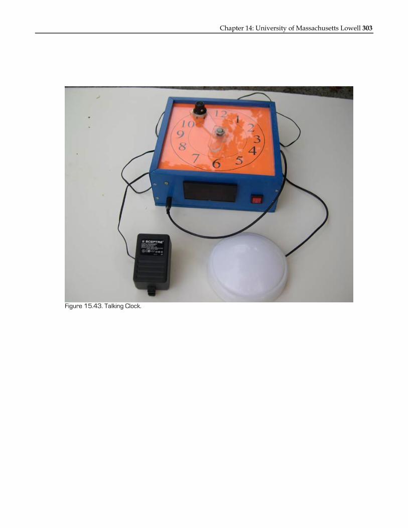
Chapter 14: University of Massachusetts Lowell 303
Figure 15.43. Talking Clock.

304 NSF 2004 Engineering Senior Design Projects to Aid Persons with Disabilities
RADIO CONTROLLED TOY WHEELCHAIR WITH SPEED CONTROL
Designer: Sharbel Azzi Client Coordinator: Lowell High School Rm#418, Lowell, MA.
Supervising Professor: Walter McGuire Electrical and Computer Engineering Department
University of Massachusetts at Lowell Lowell, Massachusetts 01854
INTRODUCTION The radio controlled toy wheelchair with speed control is designed to help students who have limited arm mobility and slow reaction time to learn cause and effect. The toy is designed so that it can be controlled with a joystick. This enables the user to move the toy wheelchair with only one hand instead of regular controllers that require the use of both hands. Speed control allows the students to determine the speed at which the wheelchair moves, giving them ample time to react to changes in direction.
SUMMARY OF IMPACT The design criteria for the radio controlled toy wheelchair are set by high school teachers of the children with disabilities as well as the design engineer. The aim of this product is to assist the teachers in teaching cause and effect. This toy is a fun learning tool for the class.
TECHNICAL DESCRIPTION The design of the toy wheelchair relies heavily on existing radio controlled cars. The car's transmitter and receiver are modified so that the speed of the
DC motor can be varied externally. The transmitter is modified so that a joystick can perform the functions of the previous switches, which require the use of both hands. The receiver, however, is not changed. Instead the speed control circuitry is placed between the outputs of the receiver and the terminals of the DC motor.
To be able to control the speed of the motor, the use of two LM555 ICs is incorporated. These chips are used to control the duty cycle of the voltage and thus the current going to the motor. By varying the duty cycle and the voltage using a potentiometer, the speed of the DC motor can be controlled. The 555 timers are turned ON and OFF depending on the signal outputted by the receiver. A forward signal turns one of the LM555 chips ON while the other timer is turned ON when a reverse signal is sent to the motor. Two LEDs placed on the wheelchair provide a visual display of the period of time the voltage is being turned on and the period of time it is being turned off. Each LED is for one direction (one for forward the other for reverse).
Total cost of parts and materials is approximately $75.

Chapter 14: University of Massachusetts Lowell 305
Figure 15.44. Wheelchair and Controller.

306 NSF 2004 Engineering Senior Design Projects to Aid Persons with Disabilities
ASSOCIATION STATION Designer: Timothy P Dineen Jr.
Client Coordinator: Bonnie Paulino, Kennedy Day School, Brighton, Ma Supervising Professor: Walter McGuire
Department of Electrical and Computer Engineering 1 University Ave Lowell MA 01854
INTRODUCTION The Association Station (AS) was designed to teach color association to children with multiple disabilities. The problem is that there are few toys that teach colors that are specifically designed for children with disabilities. This device is a toy for the teacher and student to use together. The teacher chooses a color for the student to find; if the student chooses correctly, a same-colored light blinks and a positive reinforcement message is spoken. The intent of this device is to be enjoyable and educational.
SUMMARY OF IMPACT The Association Station was designed to meet the requirements of the client school. Among the requirements was that the device allow for use by many different children with many different disabilities.
TECHNICAL DESCRIPTION The physical structure of the AS is that of a rectangular wooden breadbox. The front faces the teacher and has four color selection switches, four different colored LEDs, and an on/off switch. The back side faces the student and has four different colored LEDs, a speaker mounted in the top center, and four mono headphone input jacks. The mono inputs allow for various types of modified switches, which allow children with different disabilities to use the device.
If the teacher and student choose the same color, a signal is passed to a timing circuit (LM555) for that color, which makes the corresponding colored LEDs blink. That signal is also passed to the addressing pins of a voice chip (ISD2560) to access the correct message, and finally the signal also goes to a logic circuit (CD4002B), which, in turn, sends a signal to the voice circuit to play the message.
Figure 15.45. Child Using the Association Station.
Figure 15.46. Teacher’s Side.
Figure 15.47. Student’s Side.

Chapter 14: University of Massachusetts Lowell 307
TitleAssociation Station Circuit Schematic
Document NumberSize A
Date: Friday, May 14, 2004 Sheet 1 of 1
SW9R83k ohm
220uF
CV RSTTHRTRG
VCC GND
LM555
C4
5462
8 1
YELLOW
45
45
3 2 1
3 2 1
A
B
C
D
A
B
C
D
7 DSCHG OUT
CV RSTTHRTRG
VCC GND
5462
8
7
1
3
3
3k ohm
220uF
DSCHG OUT
LM555
SW8
SW7
SW6
1k ohm
1k ohm
R7
R6 GREEN
R5
U5
U4
CV RSTTHRTRG
VCC GND
5462
8
7 3
1
LM555
220uF
DSCHG OUT
3k ohm
1k ohmR3
R4
U3
C3
C2
SW5
SW4
SW1
BLUE
VC
C 4
.8V
CV RSTTHRTRG
VCC GND8
3
220uF
DSCHG OUT
5462
7
1
LM555
1k ohm
3k ohm
R2
R1
U2
RED
C1
SW3
SW2
CD4002
U3A23
45
6.8uF
C9R10
470k
ohm
s
C6 O.1uF
O.1uF
14
VCC
VCC
VCC
VCC+VCC
ISD2560
C5
O.1uF
20
C8
U1
A0/M0A1/M1A2/M2A3/M3A4/M4A5/M5A6/M6
A7A8A9
AUXINMIC
MICREF
PD
AGCOVFCE
EOM
XCLK
VSSD
VSSA
P/R* 27
C7
22Uf
12
13
SP+SP-
ANAIN ANAOUT 16 ohm
R9 5.1k ohms
SPEAKER
1415
21
12345678910
111718
24
19222325
26
1628
7
Figure 15.48. Circuit Schematic.

308 NSF 2004 Engineering Senior Design Projects to Aid Persons with Disabilities
SOUND ACTIVATED CAROUSEL Designer: Nha Tran
Supervising Professor: Walter McGuire Client Coordinator: Kennedy Day School, Boston, MA
Department of Electrical Engineering University of Massachusetts Lowell
Lowell, MA 01854
INTRODUCTION The basic function of the project is to activate a relay through sound. Once the relay is on, a carousel spins with an AC motor operated at low speed and the light surrounding the carousel turns on. In the process the power supply converts the 24 V AC from the output step down transformer to a 12 V DC, which is used for the sound activated circuit. A music box is used as an option when the sound activated switch is not on. The user can control it via a switch. Figure 15.49 shows the device.
SUMMARY OF IMPACT The children at a client school have many disabilities and use wheelchairs. The students have limited motor skills. The sound activated carousel is a source of entertainment for the children. All they have to do is either clap their hands or make noise to activate the device.
TECHNICAL DESCRIPTION The overall circuit was powered by AC and DC voltage. The AC voltage was used for the motor to spin the carousel, and the DC voltage was used for the sound activated switch. For this reason a power supply of 12 vDC was built for the sound activated switch. In the process, due to unwanted noise from the carousel when it spins, the sound activated switch could not operate properly. There were two different ways to solve this problem. First, the potentiometer was used to adjust the sensitivity on the sound activated switch. Secondly, the microphone was moved one foot away from the carousel to reduce the noise. In the process, a two by one foot wooden box was built to accommodate both the carousel and the microphone.
Figure 15.49 Sound Activated Carousel.

Chapter 14: University of Massachusetts Lowell 309
MUSICAL CAUSE AND EFFECT TOY Designers: Stephanie Viera
Client Coordinator: : Lowell High School, Department Of Special Education, Lowell, MA Supervising Professor: Walter McGuire & Alan Rux
Electrical and Computer Engineering Department University of Massachusetts Lowell
Lowell, MA 01854
INTRODUCTION The goal of this project is to build a fun and easy to use learning tool to teach children with disabilities cause and affect. The toy consists of four switches of different colors (blue, green, yellow and red), and LEDs with switches of the same color. Each LED is connected to the switch of the same color. Each switch has different musical sounds. When the toy is turned on, LEDs start lighting up in a random sequence. Only one LED lights up at a time. When the user presses the switch of the LED that is lit up, the toy plays songs to reward the user. If the user presses any other switch that does not correspond to the LED that is lit up, it makes no sound.
SUMMARY OF IMPACT This toy would benefit the students in many ways. Pushing the buttons on the toys strengthen fine motor skills and eye-hand coordination. The music focuses the student’s attention and teaches them to
use their hearing effectively. The music generated as they push the buttons helps reinforce cause and effect learning. The colors stimulate visual development. This toy is a great benefit for the students with disabilities to stimulate their senses as they have fun playing with the toy.
TECHNICAL DESCRIPTION Turning on the circuit automatically triggers the counter to start up the LEDs. The LM555 timer tells the counter how long the LEDs are on. The sound is recorded in the ISD chip in four different addresses. Each address is triggered when the specific LEDs connect to the address that is lit up. The LEDs and switches are connected to the ISD by an AND-Gate, which sends an active high signal to the four input NOR-Gate when both the LED and switch are high. The NOR-Gate sends a signal to the ISD to start playing the song of the LED that is lit up.
The cost of parts and material is approximately $250.
310 NSF 2004 Engineering Senior Design Projects to Aid Persons with Disabilities
INFRARED TOGGLE SWITCH FOR A MUSIC BOX Designer: Tuyen D Truong
Client Coordinator: Leona Geovanni, Abraham Lincoln Elementary School, Lowell, MA Supervising Professor: Jay Fu
University of Massachusetts, Lowell Department of Electrical and Computer Engineering
One University Avenue Lowell, MA 01854
INTRODUCTION Instead of requiring a switch to be pushed to activate a device, such as a toy or music box, infrared (IR) remote control devices produce continuous coded stream of pulses. In this project, the coded stream is converted into a single pulse and that single pulse is used to turn a relay on and off. The relay then acts as a switch to turn on a secondary device, a music box.
SUMMARY OF IMPACT The goal of this project is to design, build, and manufacture a wireless remote control that children with disabilities can use. This device helps the children to participate in activities and control their environment. Once these children understand that they can make things happen in the environment by pushing a button of a remote control, then they are ready to move on to more sophisticated interactions.
TECHNICAL DESCRIPTION All modern IR remote control devices produce a continuous coded stream of pulses at 37.9 kHz when
any button on the module is pressed. These IR pulses are detected and decoded by a receiver (TV, VCR, etc.) and the appropriate function is activated. In this project, the coded stream is converted into a single pulse and that single pulse is used to toggle a relay on and off. The coded information is lost. Only the fact that a button is pressed on the remote control unit is detected.
This single pulse is then used to toggle the output of a flip-flop. A high on the output of the flip-flop turns on a transistor, which, in turn, operates the relay and the LED. The relay acts as a switch connecting the wires of the power supply that produces power to turn on the music circuit.
The IR toggle circuit and music circuit are mounted into a box (20.32x15.4x7.6 centimeters). A DC power jack is in the back of the box for a 9 V adapter. On top of the box is the IR receiver, which senses the signal from any remote control. A speaker and a volume controller are also mounted on top. The device is shown in Figure 15.50.
The cost of parts and material is approximately $130.

Chapter 14: University of Massachusetts Lowell 311
Figure 15.50. Infrared Toggle Switch.

312 NSF 2004 Engineering Senior Design Projects to Aid Persons with Disabilities
VOICE RECOGNITION SYSTEM FOR A REMOTE CONTROLLED SPEAKERPHONE
Project Developer: Vikas Shah Instructor: Walter Mcguire
Client Location: Boston Home Electrical and Computer Engineering Department
State University of Massachusetts at Lowell, Lowell, MA 01853
INTRODUCTION The voice recognition feature on the Ameriphone Dialogue RC 200 was designed to allow an individual with motoric disabilities to utilize the phone with greater efficiency. The built–in voice recognition feature was far too sensitive, so that, when the phone rang, it picked up even if someone other than the client said hello or even with noise in the room. Also, the phone did not hang up unless there was complete silence and, in the meantime, it was connected to the operator, causing great inconvenience to the client. Hence, the built-in feature was turned off and an external voice recognition feature was developed. This feature requires only one word or a multi-word to be recognized for execution. Hence this development will allow the client to pick up, hang up and dial conveniently.
SUMMARY OF IMPACT The remote transmitter performed all the required functions. It required a single click to pick up, hang up or dial. The client trained the device using one unique word to pick up, hang up or dial the phone as needed. This made him more self-reliant and capable of making and receiving phone calls without assistance. Also, it did not pick up the surrounding noise or anyone else’s voice.
TECHNICAL DESCRIPTION The Voice Extreme Toolkit, made by Sensory Inc., is utilized for the voice recognition feature. The kit consists of: a Voice Extreme Development Board, Module, Power Supply, a Serial Cable for PC RS-232 connection, and a software CD containing required files and documentation for programming. It enables the application program to be written in a higher level language on a PC with the help of built-in functions. The application program is then linked with built-in data files. The program has access to
several I/O ports and timers. The program is then downloaded via the serial cable onto the module, which has a built-in integrated circuit, 64KB ROM and 2MB flash memory for permanent storage of the program onto the module. The module has several I/O pins, which act as an output for the program, connected to the development board. The output of these pins can be used for hardware application.
The application consists of a program that begins with a training session and checks for a previously trained command to see whether a word is initially trained. If a word is initially trained, then it directly jumps to an infinite execution loop, where it constantly looks for a word to execute. If the user speaks the trained word, the RED LED on the development board goes ON for a designated period of time (0.5 sec), showing the user that the word is recognized. The RED LED is connected to a NAND gate via a 220 Ω resistor. The NAND gate is
Figure 15.51. Remote Controlled Speakerphone.

Chapter 14: University of Massachusetts Lowell 313
connected to the output pin, which goes LOW every time a word is recognized. The output pin can be used for hardware application. If there is no trained command, the program enters a training process where it asks the user to train a word, stores it in FLASH memory and then proceeds to the infinite execution loop.
The output on the development board is used to trigger the remote transmitter via an opto-isolator. The opto-isolator has an NPN transistor output, which amplifies an approximate 8mA current received at its input through a current limiting circuit. The amplified current acts as a switch on the
remote transmitter circuit, turning it ON every time a word is recognized for the same period of time. The remote is a RF transmitter, the RF receiver located in the phone. It works well over a distance of 20 feet. A RED LED on the remote indicates its execution. An external microphone is used for the user to speak in the trained word for execution. The microphone uses two AA batteries and the power supply for the remote transmitter is tapped from the development board. The entire circuit is placed in a black box as seen in Figure 15.53.
The cost of parts and materials is approximately $175.
Figure 15.52. Voice Recognition System (Black Box and Microphone).
Figure 15.53. Internal View of Voice Recognition System (VE Kit, Remote, Microphone).
314 NSF 2004 Engineering Senior Design Projects to Aid Persons with Disabilities
PROGRAM TIMER Designer: William C Muldoon
Client: VA Hospital, Lowell, MA Supervising Professor: Jay Fu
Electrical and Computer Engineering Department State University of Massachusetts at Lowell,
Lowell, MA 01853
INTRODUCTION The Program Timer is designed to provide an environmental control system for a client who has physical disabilities. This device uses her appliances and lights to turn on or off from a Visual Basic Program that runs by X-10 modules. The modules make the home appliances and lights work with wireless control. Upon completion, the Program Timer was delivered to the client.
SUMMARY OF IMPACT The design criteria for the Program Timer were defined by the capabilities of the client and her needs at home. A portable device was designed to help the client feel safe while controlling her home environment. It also allows her to take part in the decision-making about her environment.
TECHNICAL DESCRIPTION The project integrates appliances and lights in the home. The project is used by individuals with disabilities to control their surroundings by a
handheld device or by computer commands. One method of controlling a device is by communicating to it using X-10. X-10 is a language that allows devices to talk to each other using the electrical wiring in the person’s home. The theory of X-10 is the transmission of a message that occurs close to the zero crossing of a 60 Hz power line. There is a binary one that is represented by a one millisecond burst of 120kHz at the zero crossing point. There is a binary zero by the absence of a 120 kHz burst. The complete code transmission goes 11 cycles of the power line. The first two cycles represent a start code. The next four cycles represent the house code and the last five cycles represent the number code, one through 16, or a function code, on or off. The appliances and lights accept the X-10 signal and decode it. A microcontroller decides what to do with the signal.
The total cost of material and labor is $1006.
Chapter 14: University of Massachusetts Lowell 315
TALKING PHOTO ALBUM Designer: Abbas J. Choudhry
Client Coordinator: Dr. T. Opperman, Lowell High School Intensive Needs Program, Lowell MA Supervising Instructor: Mr. Walter McGuire
Electrical and Computer Engineering Department State University of Massachusetts at Lowell,
Lowell, MA 01853
INTRODUCTION A talking photo album was designed to enhance students’ cognitive and motor skills. The device consists of a page detection system, addressing system and a record/playback system. The basic idea behind the project is to take the input from the reflective sensors, then convert the 10 binary input signals to four binary signals that will be inverted and then sent to the ISD, signaling the addressing bits, resulting in a sound signal that is amplified and relayed to the speaker. The unique characteristic that separates the album from its competitors is the page detection system.
SUMMARY OF IMPACT The talking photo album is designed to enhance students’ cognitive and motor skills. The album is to be used under supervision of therapists, especially with the recording process.
TECHNICAL DESCRIPTION The main features of the album include record and play functions. The album is in the form of a booklet
with single still images on each page. The user can record and play a message for each still image. The messages can be stored permanently or deleted. The record/playback functions are controlled via the ISD2560 voice recording chip. In addition to ISD2560, different chips, such as 257090 and 120, also can be used, depending on the length of the messages to be recorded. The schematic is the same for each chip, except the addressing varies accordingly.
Another important feature of the album is the page detection system. The user does not have to press buttons to play messages for each picture. The system consists of reflective detectors located on the left side of the booklet. The detectors consist of phototransistors and LEDs, with reflective strips at the border of each page. When each page is turned, it covers the phototransistor, and the LED turns on, indicating which page is being observed. The detectors are then connected to the encoder that takes the input signals and converts them to four binary output signals that are then inverted via hex inverter.

316 NSF 2004 Engineering Senior Design Projects to Aid Persons with Disabilities
TELEPHONE PAD Designer: Jonathan S. Lilley
Client Coordinator: Megan Leiberwirth, James S. Daly School, Lowell, MA Supervising Professor: Jay Fu
Electrical and Computer Engineering Department University of Massachusetts Lowell,
Lowell, MA 01854
INTRODUCTION The telephone pad is designed to help children learn to dial their phone numbers. The device is a tabletop box set up like a telephone. It has oversized buttons. When a button is pushed, it displays the number to a seven-segment display and presents an auditory verbal output of the number to a speaker. The box also has a standard telephone, where the same process can be implemented. The project was presented to the classroom, and the children and teachers are pleased with it. Figure 15.54 shows a photograph of the final project.
SUMMARY OF IMPACT A project was requested to help the children learn their telephone numbers. The teacher wanted a toy that the children could use without constant supervision. There were only three teachers in the classroom at any one time, and it was difficult to be with all 10 students at once. Current learning tools included large sticky numbers for the floor, where the student stepped on the number and the teacher told them if they were correct or not. They were also using numbers on a piece of paper and the teacher had the students point to a series of numbers that make up their phone number. Both of these were good learning tools; however they both required the teacher to be with the student. The teacher’s main requirements were that the toy be safe and appealing to children.
TECHNICAL DESCRIPTION The physical structure of the box was made out of half-inch plywood. 8-32 machine screws and 1/16- inch aluminum were used to make the large buttons on the pad. These buttons were SPST switches used to activate a 16-key encoder on the circuit. This encoder, when activated, sent out a binary coded decimal (BCD) over the output bus. This address
went to a pick micro-controller (16F84), which lit the seven-segment display and activated the ISD voice chip. The ISD voice chip, when activated, output the number or symbol corresponding to that address to a 16 Ω speaker.
The other input to this circuit was a standard telephone, which was connected through an RJ11 connector. The telephone was powered using eight volts, and was connected to a DTMF touchtone decoder. This chip decoded the tones from the telephone and output a BCD address over the output bus. This output also went to the pick micro-controller, which displayed the number and activated the ISD chip.
The cost of parts and material was approximately $150.
Figure 15.54. Telephone Pad.

Chapter 14: University of Massachusetts Lowell 317
DEVELOPMENTAL ELECTRONIC TOY Designers: Michael Michalik
Client Coordinator: Megan Lieberwirth, Daley Middle School, Lowell, MA 01854 Supervising Professor: Walter McGuire
Electrical and Computer Engineering Department Department of Electrical and Computer Engineering One University Ave, Lowell, Massachusetts 01854
INTRODUCTION The electronic toy was designed and built to provide audio stimulation for children with multiple disabilities. The toy will help children with disabilities to sharpen their fine motor skills by grasping and releasing the toy shapes. There are four shapes in the toy, each of which needs to be placed into its correct position on the playing surface. As each shape is placed correctly, a message is played to reward the student.
SUMMARY OF IMPACT The toy entertains the students while helping increase their independence because of its ease of use. Also, the toy frees the teachers to spend more time with other children who have more severe disabilities.
TECHNICAL DESCRIPTION The basic structure of the electronic toy is made from yellow pine wood (1 by 12 by 6 feet). The material provides high strength, low weight and workability. The top, bottom, and four sides are all screwed together with 1.5 woodscrews to allow for repair or disassembly with little effort. The structure is painted blue to enhance the toy’s appearance. In addition, the shapes are color
matched to their corresponding placement on the playing surface.
The student reward, when a shaped is placed correctly, comes from prerecorded audio messages. The recording and playback of the messages is accomplished using ChipCorder® technology by the ISD Company. The CMOS technology is an information storage device that has unlimited applications. The IC chosen for this design is the ISD 1420, which has 20 seconds of voice record/playback capabilities. This IC also allows multiple messages to be recorded and played back, which is accomplished using the fully addressable zero-power 128k multilevel storage array. For this design four messages were recorded onto the IC, one message per each shape. For example, one message is “That’s correct, square.”
The design calls for four messages each about four seconds in time duration, so only 16 of 20 seconds are needed. The IC has eight pins that are used to access 160 address spaces. The messages are recorded onto the IC using four address pins. The same four pins are implemented when a shape is placed correctly and a playback occurs.
The cost of parts and material is approximately $90.
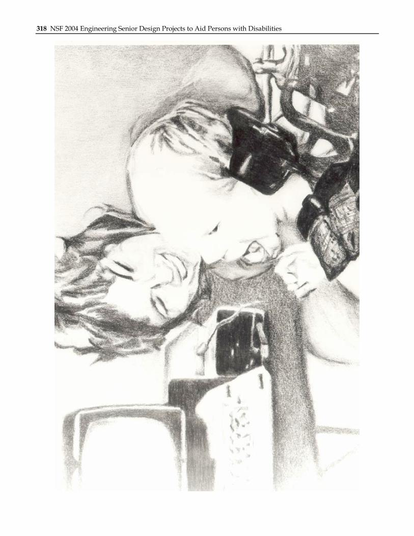
318 NSF 2004 Engineering Senior Design Projects to Aid Persons with Disabilities