chapter 13: the conditions of rotary motionusers.etown.edu/w/wunderjt/syllabi/chapter 13 revised for...
TRANSCRIPT
Chapter 13Conditions of Rotary Motion
KINESIOLOGYScientific Basis of Human Motion, 11th edition
Hamilton, Weimar & Luttgens
KINESIOLOGYScientific Basis of Human Motion, 11th edition
Hamilton, Weimar & LuttgensHamilton, Weimar & Luttgens
Presentation Created by
TK Koesterer, Ph.D., ATCHumboldt State University
Revised by Hamilton & Weimar
REVISED FOR FYS by J. Wunderlich, Ph.D.
Hamilton, Weimar & Luttgens
Presentation Created by
TK Koesterer, Ph.D., ATCHumboldt State University
Revised by Hamilton & Weimar
REVISED FOR FYS by J. Wunderlich, Ph.D.
Agenda
1. Eccentric Force àTorque (“Moment”)2. Lever3. Force Couple3. Force Couple4. Conservation of Angular Momentum5. Centripetal and Centrifugal Forces
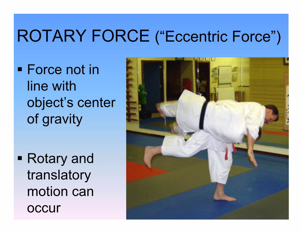
ROTARY FORCE (“Eccentric Force”)
§ Force not in line with object’s center of gravityof gravity
§ Rotary and translatory motion can occur
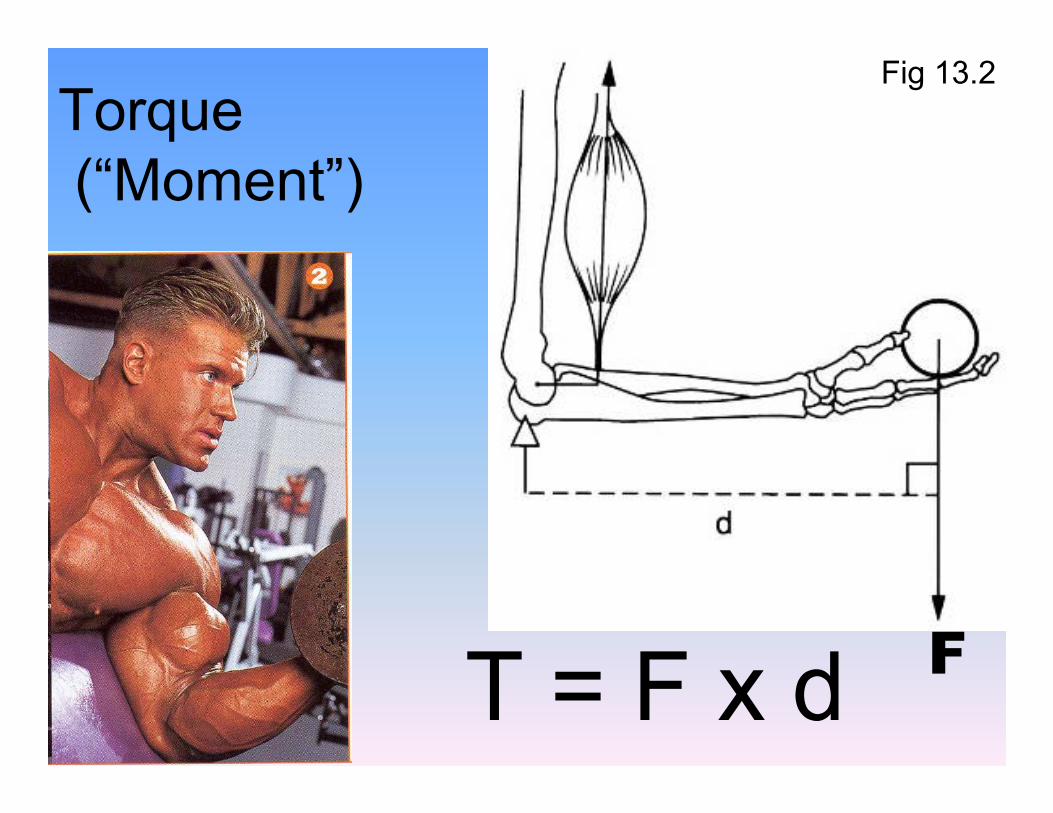
Torque(“Moment”)
Fig 13.2
T = F x d F
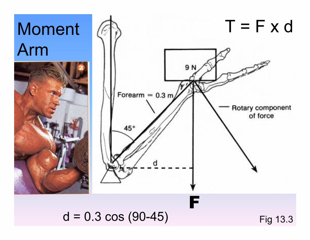
Moment Arm
T = F x d
d = 0.3 cos (90-45) Fig 13.3
F

T = F x d
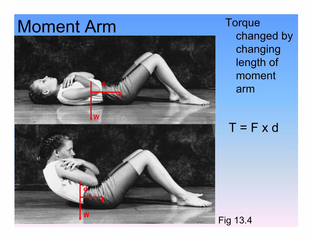
Torque changed by changing length of moment arm
W
d
Moment Arm
T = F x d
Fig 13.4
W
W
d
T = F x d

Sum of Torques (“Moments”)T = F x d
Fig 13.8
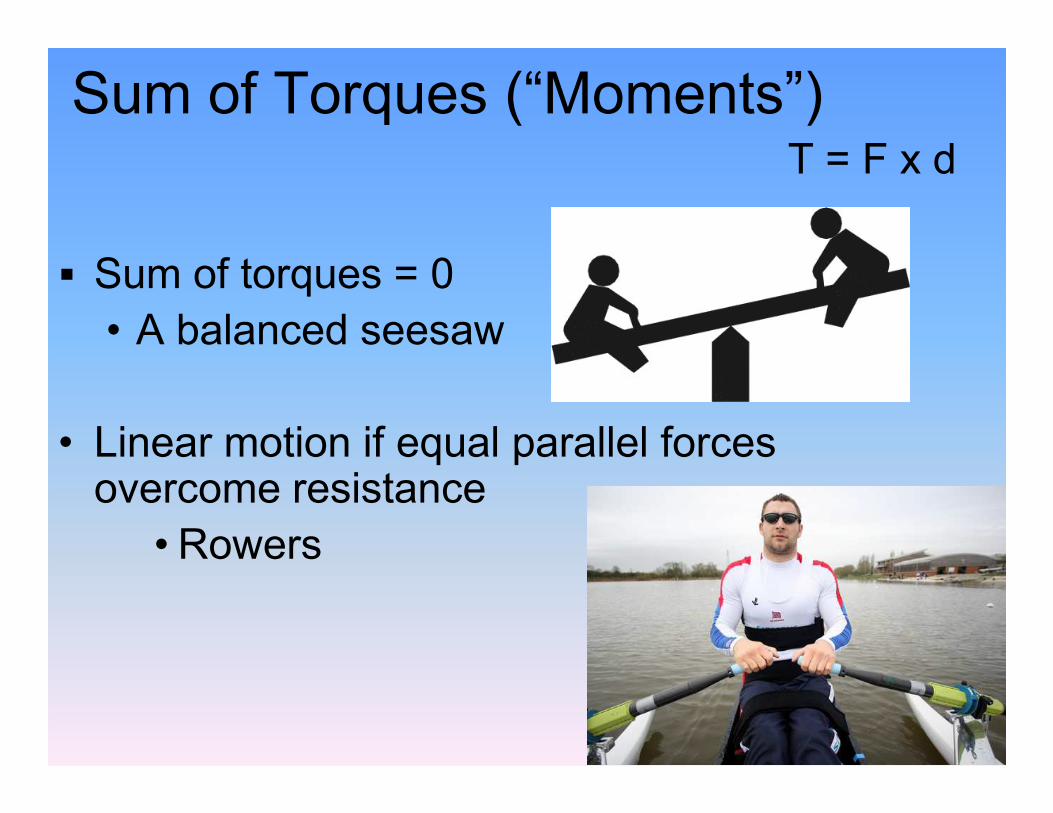
Sum of Torques (“Moments”)
§ Sum of torques = 0• A balanced seesaw
T = F x d
• Linear motion if equal parallel forces overcome resistance
• Rowers
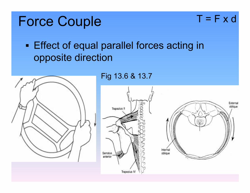
Force Couple
§ Effect of equal parallel forces acting in opposite direction
Fig 13.6 & 13.7
T = F x d
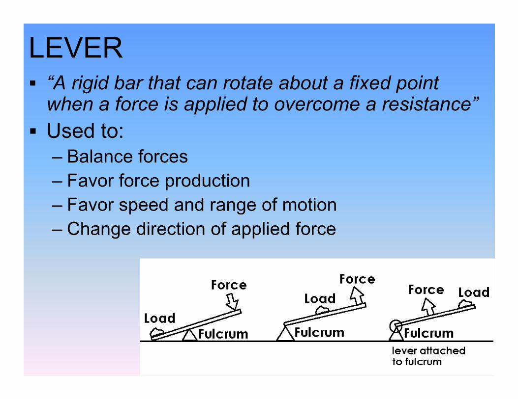
LEVER § “A rigid bar that can rotate about a fixed point when a force is applied to overcome a resistance”
§ Used to:– Balance forces– Favor force production– Favor speed and range of motion– Favor speed and range of motion– Change direction of applied force

External Levers§ Small force to overcome large resistance§ Crowbar
§ Large Range Of Motion to § Large Range Of Motion to overcome small resistance § Hitting golf ball
§ Balance force (load)§ Seesaw
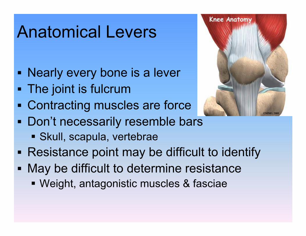
Anatomical Levers
§ Nearly every bone is a lever§ The joint is fulcrum§ Contracting muscles are force§ Don’t necessarily resemble bars§ Don’t necessarily resemble bars
§ Skull, scapula, vertebrae§ Resistance point may be difficult to identify§ May be difficult to determine resistance
§ Weight, antagonistic muscles & fasciae
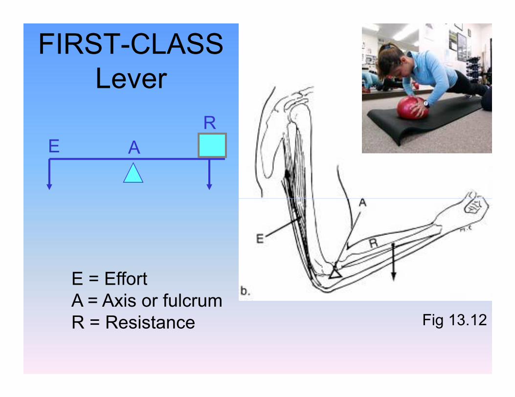
FIRST-CLASS Lever
RE A
Fig 13.12
E = EffortA = Axis or fulcrumR = Resistance

SECOND-CLASS Lever
R
EA
E = EffortA = Axis or fulcrumR = Resistance
Fig 13.13

THIRD-CLASS Lever
R
EA
E = EffortA = Axis or
fulcrumR = Resistance
Fig 13.14
Muscle Force Vectors
§ Rotary component for torque production§ Stabilizing component acts along mechanical axis of bone through axis of mechanical axis of bone through axis of rotation§ Thus not eccentric
§ Moment arm zero
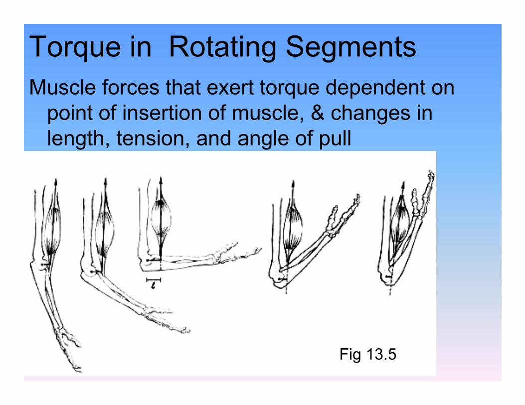
Torque in Rotating SegmentsMuscle forces that exert torque dependent on point of insertion of muscle, & changes in length, tension, and angle of pull
Fig 13.5
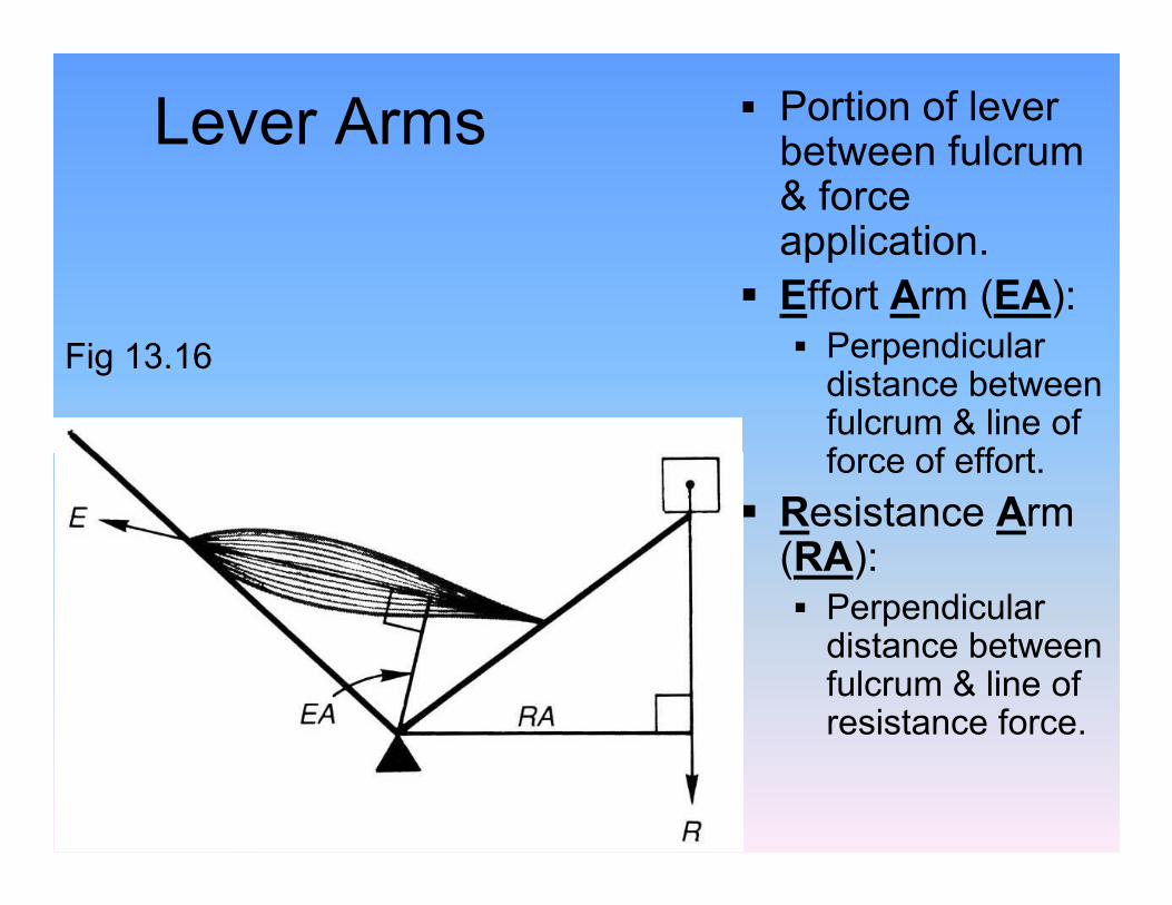
Lever Arms § Portion of lever between fulcrum & force application.
§ Effort Arm (EA): § Perpendicular distance between fulcrum & line of force of effort.
Fig 13.16
force of effort.
§ Resistance Arm (RA): § Perpendicular distance between fulcrum & line of resistance force.

Selection of Levers§ Longest lever arm not always best
– Short levers enhance angular velocity, while sacrificing linear speed and range of motion
– Strength needed to maintain angular velocity increases as the lever lengthens
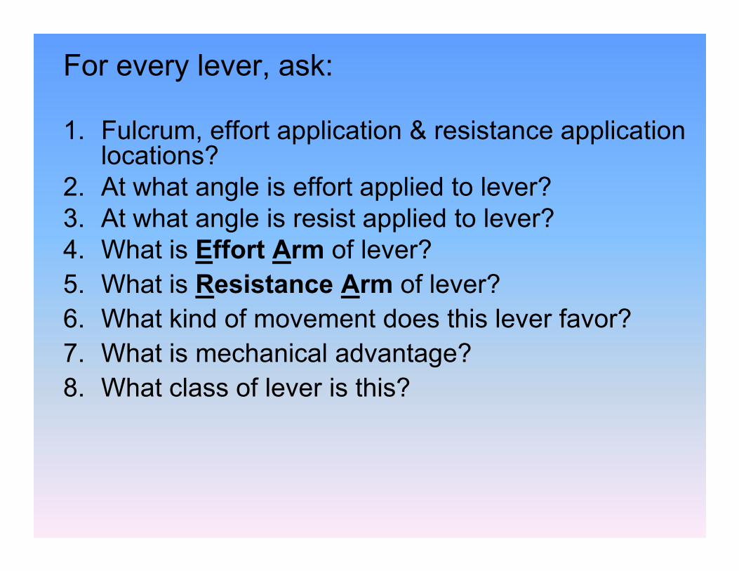
For every lever, ask:
1. Fulcrum, effort application & resistance application locations?
2. At what angle is effort applied to lever?3. At what angle is resist applied to lever?4. What is Effort Arm of lever?5. What is Resistance Arm of lever?5. What is Resistance Arm of lever?6. What kind of movement does this lever favor?7. What is mechanical advantage?8. What class of lever is this?
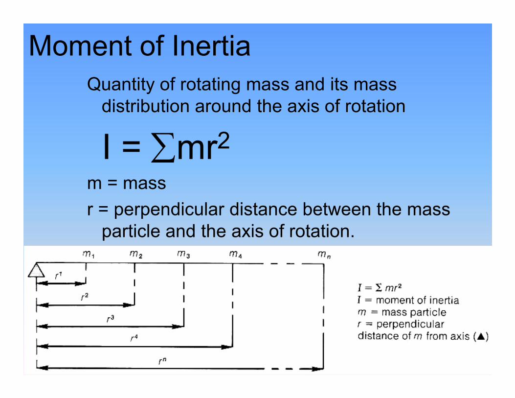
Moment of Inertia Quantity of rotating mass and its mass distribution around the axis of rotation
I = ∑mr2m = massr = perpendicular distance between the mass r = perpendicular distance between the mass particle and the axis of rotation.
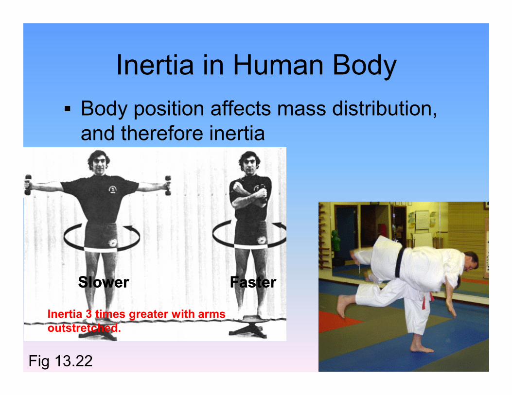
Inertia in Human Body§ Body position affects mass distribution, and therefore inertia
Inertia 3 times greater with arms outstretched.
SlowerSlower FasterFaster
Fig 13.22

Torque due to Angular AccelerationThe rotational equivalent ofF = ma:
T = IαT = IαI = Moment of Inertiaα = Angular Acceleration
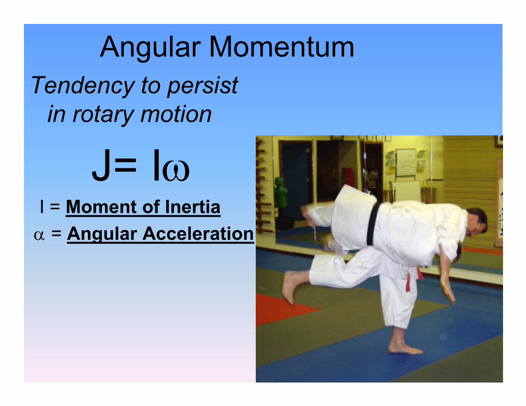
Angular MomentumTendency to persist in rotary motion
J= IωI = Moment of InertiaI = Moment of Inertiaα = Angular Acceleration
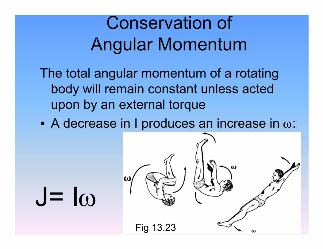
Conservation of Angular Momentum
The total angular momentum of a rotating body will remain constant unless acted upon by an external torque
§ A decrease in I produces an increase in ω:§ A decrease in I produces an increase in ω:
Fig 13.23
J= Iω
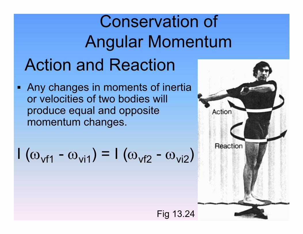
Action and Reaction§ Any changes in moments of inertia or velocities of two bodies will produce equal and opposite momentum changes.
Conservation of Angular Momentum
momentum changes.
I (ωvf1 - ωvi1) = I (ωvf2 - ωvi2)
Fig 13.24

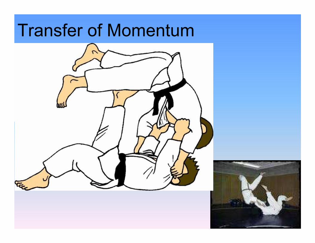
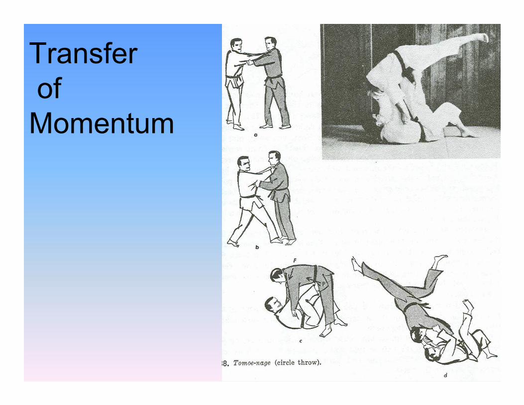
Transfer of Momentum
§ Angular momentum may be transferred from one body part to another as total another as total angular momentum remains unaltered
§ Angular momentum can be transferred into linear momentum, and vice versa Fig 13.25
Transfer of Momentum
Transferof Momentum
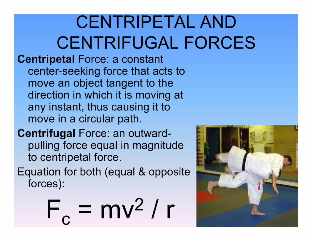
CENTRIPETAL AND CENTRIFUGAL FORCES
Centripetal Force: a constant center-seeking force that acts to move an object tangent to the direction in which it is moving at any instant, thus causing it to move in a circular path.move in a circular path.
Centrifugal Force: an outward-pulling force equal in magnitude to centripetal force.
Equation for both (equal & opposite forces):
Fc = mv2 / r
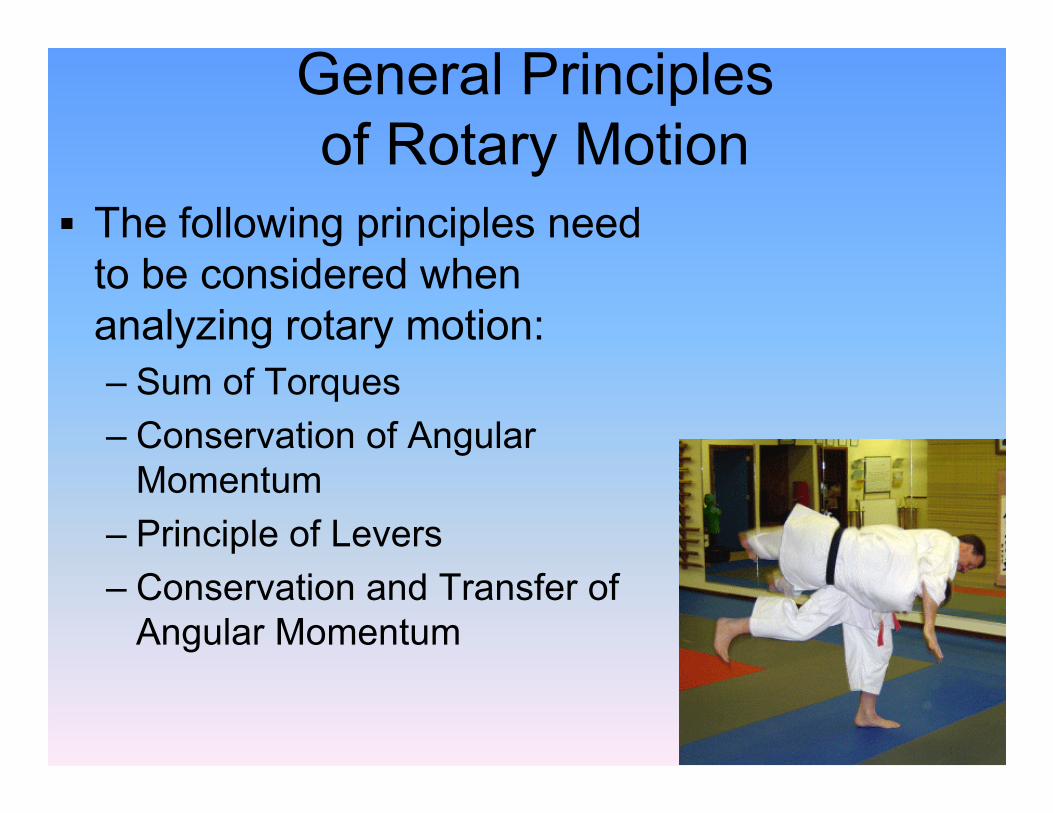
General Principles of Rotary Motion
§ The following principles need to be considered when analyzing rotary motion:– Sum of Torques– Conservation of Angular Momentum
– Principle of Levers– Conservation and Transfer of Angular Momentum
