chapter 13. sealing abandoned wells and boreholesdrilled. to seal an abandoned well properly, the...
TRANSCRIPT

Page 192 of 360
technology and increased numbers of well-trained and experienced hydrogeologists, should lead to the solution of many of our present groundwater contamination problems.
CHAPTER 13.
SEALING ABANDONED WELLS AND BOREHOLES
Abandoned wells and completed boreholes need to be sealed carefully to prevent pollution of the groundwater source, eliminate any physical hazard, conserve aquifer yield, maintain confined head conditions, and prevent poor-quality water of one aquifer from entering another. The principal objective of sealing abandoned wells is to restore, as far as possible, the original hydrogeologic conditions. Before being sealed, the well should be checked to insure that there are no obstructions that may interfere with effective sealing operations. This inspection is especially important in wells that could conduct undesirable water into aquifers yielding potable water. If the casing has not been grouted, it may be removed by hydraulic jacks or by bumping the casing up using a hammer. A vibration hoarser can also be used to remove casing. If the casing is in good condition, a trip-type casing spear operated by a fishing string can be used to remove it. Casing cutters are used to separate the drive shoe from the lowest casing to facilitate removal of the casing. Removal of liner pipe from some wells may be necessary to assure an effective seal. Liners or casings opposite water-bearing zones should be removed car perforated with a casing ripper beforehand to assure proper sealing throughout these zones. The upper portion of the casing should be removed to assure contact of the grout with the wall of the hole, to form a watertight plug in the upper 15 to 20 ft. Exceptions to this procedure may be permitted where the annular space around the casing was carefully cemented when the well was originally drilled. To seal an abandoned well properly, the groundwater conditions at the site must be considered. When the groundwater occurs under unconfined conditions, the objective is to prevent the percolation of surface water through the well bore or along the outside of the casing to the water table. This is accomplished by grouting the entire well bore. When confined conditions exist, the sealing operations must confine the water to the aquifer in which it occurs. This prevents the loss of confining pressure that results from uncontrolled flow from the aquifer. In flowing wells, the water level must be lowered to control the flow before placing the seal. Flow can be controlled by introducing high-specific-gravity fluids to stop the flow, extending the pipe high enough above the land surface to stop the flow, or by pumping the problem well or nearby wells to create a drawdown in the well to be sealed. Depending on the flow conditions encountered, three types of seals can be used to properly abandon a flowing well. Intermediate seals are placed between confined water-bearing

Page 193 of 360
formations having different static heads; thus, no water can pass from one aquifer to another. Bridge seals are cement or weighted wood plugs placed beneath the major aquifers. The lower part of the hole can be filled, if desired, with disinfected fill. Top seals are placed above the aquifers and form the base for the neat cement grout. Concrete or cement grout used to fill the well below the water level should be placed from the bottom up, by methods that will avoid segregation or dilution of material. 13.1. ABANDONMENT of WELLS All boreholes greater than 10 feet deep or which intersect a water table and all groundwater monitoring wells should be properly abandoned. One should consider the following factors in determining whether a borehole or monitoring well should be abandoned: purpose, location, groundwater quality, age and condition of the well or borehole potential for groundwater contamination and well or borehole construction. 13.2. GENERAL TIMELINES FOR ABANDONMENT A borehole should be abandoned within 3 working days after its use has been discontinued. Any permanent groundwater monitoring well no longer being used to gather information on geologic or groundwater properties should be abandoned within 60 days after its use has been discontinued. Any groundwater monitoring well found to be acting as a conduit for groundwater contamination shall be abandoned immediately. Potable water wells should be abandoned according to local rules. 13.3. GENERAL ABANDONMENT PROCEDURES Boreholes. Any borehole intersecting the Water table or greater than 10 feet deep, whose use has been discontinued, can be abandoned according to the following as applicable. Monitoring wells impermeable annular space seals. A permanent groundwater monitoring well known to be constructed with an impermeable annular space seal can be abandoned according to the sealing requirements after the protective cover pipe and ground surface seal have been removed arid the well casing cut off at least 4 feet below the ground surface. The well casing may be completely removed during abandonment by pulling the well casing, overdrilling around the casing and then pulling the well casing out of the ground or by drilling out the well casing completely. If the well casing is to be removed, the well shall be sealed as the casing is removed. Monitoring wells - permeable annular space seals, wells in waste areas and monitor wells on known hazardous waste sites. A groundwater monitoring well not known to be constructed with an impermeable annular space seal or located in an existing or planned future waste disposal or treatment area shall be abandoned by removing the protective cover pipe and the ground surface seal and then completely removing the well casing. The well casing can be pulled out of the ground as the well is filled according to the sealing requirements.

Page 194 of 360
Sealing requirements. Boreholes and groundwater monitoring wells should be abandoned by complete filling with neat cement grout, Bentonite cement grout, sand-cement grout, concrete or bentonite-sand slurry, Bentonite chips or granular Bentonite. A tremie pipe should be used to abandon groundwater wells and boreholes greater than 30 feet in depth or with standing water. Groundwater monitoring wells and boreholes greater than 100 feet in depth should also be sealed with a tremie pipe-pumped method. Bentonite may be used as a sealing material without the use of a tremie pipe under the following conditions: 1. Granular bentonite may be used for boreholes and groundwater monitoring wells less than 25 feet deep and when there is no standing water above the filter pack seat 2. Bentonite pellets may be used for boreholes and groundwater monitoring wells less than 50 feet deep and the depth of standing water is less than 30 feet. 3. Bentonite chips may be used for boreholes and groundwater monitoring wells which are greater than 4 inches in diameter and less than 250 feet deep and the depth of standing water is less than 150 feet. 13.4. SEALANT SETTLEMENT Any settling of the sealant material shall be topped off. Sealing material may be terminated 3 feet below the ground surface in agricultural areas to avoid interference with agricultural activities. A native soil plug should be placed on top of the settled sealing material in such cases. 13.5. ABANDONMENT DOCUMENTATION All borehole and permanent groundwater monitoring well abandonments must be documented. Special forms may be required by regulatory agencies. Decontamination procedures used during abandonment should also be documented so that no cross contamination is allowed to occur. 13.6. CONCLUSIONS Although known cases of groundwater contamination affect only a small percentage of all groundwater resources in the United States, most groundwater that is contaminated lies in highly populated areas. Therefore, the impact of the contamination is greater because of the number of people affected. Drilling contractors can take an active role in protecting their customers from groundwater contamination by constructing safe wells and making sure that old wells are abandoned properly.
CHAPTER 141.
1 The material in this chapter is based on and drawn from the AASHTO copyrighted publication Manual on Subsurface Investigations - 1988, as described in the 'Acknowledgement' section of this book.

Page 195 of 360
SUBSURFACE EXPLORATION
TOOLS AND EQUIPMENT The geotechnical parameters which affect design and construction of a facility must be investigated and evaluated. A specific, well-integrated and flexible subsurface exploration program, generally conducted in several phases, is necessary to develop the maximum amount of geotechnical data for reasonable costs. 14.1. GENERAL PLANNING The purpose of the "Office Reconnaissance" is to obtain and evaluate as much information as possible about the project area in the early planning stages. This information is then utilized in developing a subsurface exploration program which will determine the characteristics of the materials and structures in the ground to the degree necessary for the location, design and construction of the facility. Although the level of importance of the various parameters will vary with the project type and location, preliminary information should be obtained regarding the following subsurface conditions during early stages of design: 1. Soil and Rock Stratigraphy 2. Hydrological Conditions 3. Soil Classification, Density and Consistency 4. Rock Quality and Discontinuities 5. "Mixed Face" Conditions 6. Obstructions (such as boulders) 7. Hazards (such as methane gas) 14.2. EXPLORATION PROGRAM The project geologist, hydrogeologist or geotechnical engineer, when formulating the subsurface exploration program, must carefully evaluate the variety of methods and procedures which are available, in order to maximize the amount of information obtained and minimize associated costs. 14.2.1. Exploration Plan An initial exploration plan is prepared from the information evaluated during the preliminary investigation phases; it includes location, spacing and depths of explorations, and sample type and interval. There are many variables involved in the formulation of this plan. The objective should be the development of the maximum amount of subsurface information through the use of the minimum number of boreholes. The initial plan should be flexible. The proposed boring locations should always be checked against actual field conditions, prior to commencing the explorations, as modifications or adjustments may be required due to access or other restraints.

Page 196 of 360
14.2.2. Types of Borings The following terminology can be used for boring identification during the various phases of the investigation program Pilot Borings. Pilot borings are conducted during the preliminary or initial investigation stages of the project. These borings are placed at scattered locations to obtain only sufficient information to enable the project manager to: · Establish the preliminary profile. · Estimated the preliminary quantities of soil and rock items of construction involved in the project. Control Borings. Control borings are the designated first-phase design borings which are conducted at selected and key locations. Verification Borings. Verification borings are additional design banngs which are scheduled following the analysis of the control borings. 14.2.3. Exploration Spacing The locations of the explorations are subject to runny variables and depend on the uniformity of the geological units and the type of facility proposed. If the subsurface conditions in the project area are well known, and the stratification is simple, with relatively thick individual strata of consistent physical properties, relatively widely-spaced explorations may be sufficient. If, however, erratic and rapidly changing conditions exist, more closely spaced explorations will be required. Inclined borings may be used to advantage in exploring inclined strata and various subsurface irregularities. Inclined boreholes furnish information in both a vertical and horizontal direction. Borings are generally staggered to give the broadest coverage. The term "subsurface explorations" usually implies test borings; however, a variety of exploration methods such as hand or machine excavated test pits and probings conducted at selected locations may meet the project requirements and minimize investigation costs. Critical-Area Explorations. In areas where the preliminary investigations indicate critical geological conditions such as a highly irregular and shallow bedrock surface, swamp deposits or underground caverns, it may be desirable to obtain explorations on a closely spaced grid pattern in the area of concern. 14.2.4. Sampling Requirements An objective of the subsurface exploration program is to obtain samples that are representative, or nearly so, of the in sin' soil and rock conditions. The sampling

Page 197 of 360
requirements, including type and interval, are subject to the same geological variables and project requirements which control the location and depth of the explorations. Generally, representative in situ samples should be obtained at every change in soil strata and at an interval not to exceed 5 ft. vertically. Ibis interval may be increased in thick uniform deposits or be decreased in the more complex sediments. It may be advantageous in areas of erratic conditions or immediately beneath foundation bearing elevations to obtain representative samples continuously. Rock core, due to the nature of the sampling devices, is usually obtained continuously. The recovered sample is examined and logged by qualified field personnel and a representative portion or portions are selected and preserved, usually in glass jars. Occasionally, it may be preferable to preserve the entire sample that is recovered for more detailed analysis and testing. 14.3. Right-of-Entry, Permits and Utilities Prior to commencing the actual field exploration program, the owners of the property where the work will be performed must be contacted and permission obtained to conduct the work. This permission should cover rights of access and conduct of the work and any special provisions required by the property owner, such as working hours and cleanup. Certain public and private property, such as navigable waters, railroad property and public streets, may require special permits for right-of-entry. These working permits may involve a fee or special insurance and are usefully obtained by the drilling contractor. The location of any underground or overhead utilities must be determined before commencing the drilling operations. Regardless of the procedures followed or who obtains the venous rights-of-entry and clearances, these functions should be completed prior to moving any equipment into the field 14.4. Borehole Location Tolerance The allowable tolerance for the field locations of the explorations in relation to the plan locations is subject to major variations depending on the level of the exploration program, degree of complexity of the subsurface conditions, and anticipated use of the information obtained. The borehole location tolerances should be established by the project geologist or geotechnical engineer for the specific site investigation and may vary from one foot to tens of feet. Site access and underground utilities may dictate locations beyond the limits of any established tolerances. 14.5. Drilling Equipment A great variety of conventional and modified drilling rigs are available. Test boring equipment is manufactured in a number of sizes and styles, ranging from small, handheld portable drills and augers, to missives off-shore mineral exploration equipment. The selection

Page 198 of 360
of the drilling equipment is an important aspect of any subsurface exploration program. The equipment must be capable of meeting all, or as many of the project requirements as possible, have sufficient mobility and possess the ability to convert rapidly from one drilling technique to another. Hydraulic-feed machines are usually preferable, especially when they can maintain a constant advance pressure through varying formation densities, which minimizes erosion and disturbance of the in sin' materials. The project requirements or site conditions may be such that special drilling or sampling equipment is required or that supplemental logistics are necessary in realizing the project goals. 14.6. Exploration Methods The selection of the specific drilling equipment and methods to be used for a particular site investigation are dependent upon a number of factors. These may include site accessibility, equipment availability, and geologic conditions, in addition to economic and environmental considerations. New exploration technology which is still in various development or experimental stages shows a potential for possible future utilization in minimizing subsurface unknowns. These methods include long distance horizontal boreholes, acoustic borehole logging, and a variety of recently developed geophysical methods. 14.7. Borehole Advancement The more commonly used borehole advancement techniques may be classified into six groups, depending on the method used is displacing or removing material during penetration of the borehole. They are: • Displacement Boring • Wash Boring • Percussion Drilling • Rotary Drilling • Auger Boring • Continuous Sampling

Page 199 of 360
The quality of information obtained from the various methods vanes with the character of the subsurface geologic conditions; therefore, careful consideration must be given when selecting the desired method. It may be necessary to employ more than one method in advancing a particular borehole. Displacement Borings. This method is the most simple and economical test boring procedure in non-caving ground. There is no attempt to stabilize the borehole and closed samplers such as the split tube, cup, or piston sampler are forced in a closed position to the required sampling depth. This method is generally employed in preliminary reconnaissance work where only general subsurface information is required.

Page 200 of 360
Wash Borings. This method involves advancing steel casing, as required, and washing out the material to the bottom of the casing or desired sampling depth below the casing, with a variety of chopping bits. The drill rods and chopping bits are alternately raised and dropped, with some hand rotation, to break up the material within the casing; the loosened materials (cuttings) are then carried to the surface by the recirculating drilling fluids. The borehole may be stabilized with casing, water, or drilling mud. Open samplers such as the split or solid tube types, are then driven into the "undisturbed" material at the bottom of the borehole.

Page 201 of 360
Rotary Drilling. Rotary drilling is a very versatile and adaptable technique which may be used with a range of equipment models and sampling devices. Rotary drilling consists of advancing a cased or uncased borehole by rapid rotation and pressure on the drill bit which cuts and grinds the sediments at the bottom of the borehole into small particles called "cuttings". These cuttings are subsequently removed from the borehole by pumping air, water or drilling mud from a surface reservoir through the drill rods to the bottom of the borehole.
Auger Borings. The use of rotary auger drilling methods is a rapid and economical method of conducting subsurface explorations. There are certain inherent limitations when using this type of procedure, which should be carefully evaluated for the site specific exploration programs. Auger boring techniques may be divided into three categories depending on the type of auger equipment used:

Page 202 of 360
• Construction augers
• Solid flight augers
• Hollow stem augers
Construction augers are generally very large diameter solid flight or bucket type augers which are used for visual inspection of very shallow, near-surface overburden conditions. Construction augers are not designed for soil sampling; however, a large amount of material may be brought to the surface for bunk sampling, if required. Solid or continuous flight angering is generally the fastest method of obtaining a borehole in soil that is compatible to auger exploration. Samples are obtained from the auger flights. In addition, if the soils contain sufficient cohesion to enable the borehole to remain open, the augers may be removed from the borehole at any desired depth and conventional samples obtained at that depth. In loose granular soils and high water table conditions, this is rarely the case. Obstructions such as large boulders will usually stop auger penetration. Solid flight augers are available in sizes ranging from 2 - 12 in diameter. Depth penetration is generally a function of the size of the power source. Usually, auger borings are employed in preliminary exploration phases or where only near-surface information is required. Hollow stem angering is an improved modification to the solid flight augers and is extensively used for geotechnical explorations. A removable center plug in the auger allows conventional sampling tools to be lowered to the bottom of the borehole without removal of the augers. The augers, in effect, function as temporary casing. In relatively stiff formations, the center plug may be eliminated during drilling or conventional wash boring techniques may be used in conjunction with the hollow stem angering technique. Figure 14.2 shows a schematic diagram of the hollow stem auger with its removable center plug. Hollow stem augers are available with inside diameter dimensions ranging from 2.25 - 12.25 in. Although the bore wall collapse problem is eliminated with hollow stem augers, high water table conditions in loose or medium dense granular soils will tend to "blow in" or flow up inside the casing. Drilling mud can be injected during auger advancement with a spindle adaptor to allow penetration below the groundwater table. Another disadvantage when using hollow stem augers, is that the soil conditions between the samples is generally not known and some disturbance of the natura1 ground beneath the augers may occur which might not be acceptable for in site borehole crumpling and testing.

Page 203 of 360
Hollow stem augers are particularly adaptable to drilling in hard or dense sediments where drilling water is difficult to obtain or where below-freezing temperatures preclude the effective use of water for drilling. Continuous Sampling. A variety of sampling tools may be used to obtain continuous representative samples, with any test boring procedure. Such sampling may provide more reliable and detailed information on subsurface conditions. In some soil conditions, particularly cohesive soils with adequate shear strength, continuous sampling may be employed alone; in effect, creating an uncased borehole. However, it is usually necessary to clean out the borehole using conventional boring techniques, between samples, resulting in the need for some form of borehole stabilization. A continuous cold of soil or rock samples provides the most accurate picture of subsurface conditions. 14.8. Borehole Stabilization A problem common to all test bonny methods is the necessity of maintaining borewall and bottom stability in order to obtain relatively undisturbed samples of the desired stratum. The subsurface conditions encountered in a specific area will generally dictate or influence the selection of the borehole stabilization methods, which can be grouped into six general categories:
• Water Stabilization
• Mud Stabilization
• Air Stabilization
• Casing Stabilization
• Grout Stabilization
• Freezing Stabilization As with the various techniques which may be employed in advancing the boreholes, the selected stabilization method may also affect the quality of the sample recovered. Several different methods may be employed in a single borehole, in any combination, to provide the most representative sample. Water Stabilization. A recycling or continuous water supply system is the most common and economical method of maintaining borehole stability. Water induced into the borehole will generally counteract soil and pore-water pressures in partially or fully saturated sediments for a sufficient length of time to allow sampling at the selected stratum. Water alone will generally not prevent the caving or sloughing of the borehole in soft or cohesionless sediments, especially above the water table. An uncased borehole,

Page 204 of 360
utilizing water for stabilization purposes, is typically used in rock or in relatively stiff, cohesive soils. Mud Stabilization. Drilling mud is simply a mixture of water and mineral particles in suspension which has a specific gravity and viscosity greater than water. It may be a natural or artificially premixed fluid which is recycled through the uncased borehole to maintain a state of equilibrium, transport the borehole cuttings to the surface, and act as a coolant for the drill bit. It is also employed to improve sample recovery and minimize soil disturbance in cased boreholes. The basic mud mixture which is used on many subsurface exploration programs is bentonite and fresh water (approximately six percent bentonite by weight). Attapulgite, a non-flocculating clay, will make a suitable mud when mixed with salt water. Weight additives, such as pulverized barite, hematite, galena, or other heavy mineral products, may be added to the mixture to further increase specific gravity in unstable soils or in the presence of artesian conditions. The drilling mud must be carefully mixed and monitored during the life of the test boring. Driller expose is required to maintain the correct mixture balance for optimum performance. Air Stabilization. The application of compressed air which is circulated through the borehole to remove cuttings is also a method of borehole stabilization. This method is usually applied with large rotary or percussion drilling equipment where excessively dense soils, rock or obstructions must be penetrated. The drilling method may combine both rotary and percussion techniques through the use of down-the-hole hammers. A continuous column of "dry" sample is bought to the surface for evaluation and sampling A foam flushing agent may be added to assist in removing the heavier cuttings which will also have the added benefit of lubricating and sealing the borehole walls. Although conventional sampling methods are usually not conducted with this procedure, it can be adapted for a variety of sampling techniques, but with some difficulty and at a major loss in production rates. Borehole stabilization and drilling with air is generally not a practical technique in cohesive soils below the water table. Casing Stabilization. Driving heavy duty steel pipe or casing provides the most reliable, although relatively expensive, method of advancing a borehole to its required depth and maintaining stability of the borehole walls. The casing is usually advanced by constant blows of a drive hammer (typically 350 lb; falling 2 ft) upon a drive head which is attached to the casing (Figure 14.3). As the blows to drive the casing supply constant energy, supplementary information may be obtained on the soil resistance by counting the number of blows per foot and the resulting penetration. The casing is usually driven in increments of 5 ft with representative samples being obtained at the completion of each drive. The increments may be varied to meet specific sampling requirements.

Page 205 of 360
Various sizes of casing may be "telescoped" within each other to facilitate the coning of obstructions car to reduce the desired size of the borehole at depth
The heavy duty steel casing may also be equipped with a diamond bit "shoe" and drilled, rather than driven, to the required sampling depth. This procedure will allow the penetration of obstructions without a decrease in borehole size. After the casing is seated at the required depth, the hole must be thoroughly cleaned out before obtaining a sable. In soft or loose materials, stability of the borehole bottom is increased by keeping the casing filled with water or drilling fluids.

Page 206 of 360
Grout Stabilization. A borehole may encounter local zones of instability in the bedrock due to shear zones, faults, weathering or fractured rock which prevents deeper penetration of the drilling tools.

Page 207 of 360
This zone may be stabilized by pumping a cement or chemical grout into that portion of the hole and redrilling the borehole through the hardened plug. Although additional time may be required for setting of the grout, it may be preferable to advancing casing to this depth, which would also reduce the borehole size. This method may also be applied in extremely unstable areas in the overburden. Freezing Stabilization. A borehole may be stabilized by freezing the soil through which it passes by replacing the driving fluid with alcohol, diesel fuel or a brine solution which is chilled with "dry ice”. This method is generally not applicable in unsaturated ground or where there is a strong groundwater flow, and it also represents an environmental concern from the standpoint of pollution. In some instances, it may be advantageous to use this procedure to recover "undisturbed" samples of naturally frozen granular soils to determine the presence of ice tensing or segregation. 14.9. Special Exploration Techniques A variety of subsurface exploration techniques, which range from simple to very sophisticated, may be used to determine or supplement information concerning the geological conditions in the project area Any exploration technique which can properly evaluate the geotechnical parameters which win effect the design of the project is usually acceptable. Frequently, the most simple and economic methods, which are often overlooked, may be the most suitable. Occasionally, the very sophisticated and expensive methods are the only techniques which will provide the necessary information. Several special exploration techniques are summarized below to indicate the range and level of these techniques. Exploratory Probes. Exploratory probing techniques are employed as preliminary or supplementary measures to determine the gross characteristics and depths of relatively thin surficial soil deposits. • Hand Probes. Hand probes are made to obtain reconnaissance information in
wetland areas, concerning the thickness and lateral extent of soft, compressible organic soils. Small diameter, flush coupled, steel rods are pushed by hand to refusal in the underlying inorganic soil.
• Rod Probes. Rod probes can be conducted with any conventional drilling equipment
to provide general information on soil penetration resistance and depth to bedrock or refusal. Standard drill rods equipped with a point are driven or rotary-drilled to the required depth or refusal. Rod probes may be employed to supplement conventional subsurface exploration methods.
• Auger Probes. Auger probes can be conducted with rotary drill rigs equipped with
solid flight augers to provide general information on soil types, penetration resistance,

Page 208 of 360
groundwater conditions and depth to bedrock or refusal An advantage of auger probes over other probing methods is that soil is returned to the surface for general analysis and a borehole is created which, if remaining open, may be utilized for groundwater observation purposes.
• Percussion Probes. Air operated percussion drilling equipment may be used to obtain
additional information on the depth of relatively shadow bedrock, especially in areas where very dense or "bouldery" overburden overlies bedrock. This equipment may be employed in conjunction with an acoustical listening device to more accurately define the subsoil and rock conditions.
• Hand Explorations. The most basic of all exploration tools is the shovel and its use
for examining in detail the near surface soil conditions should not be overlooked. Other hand explorations include:
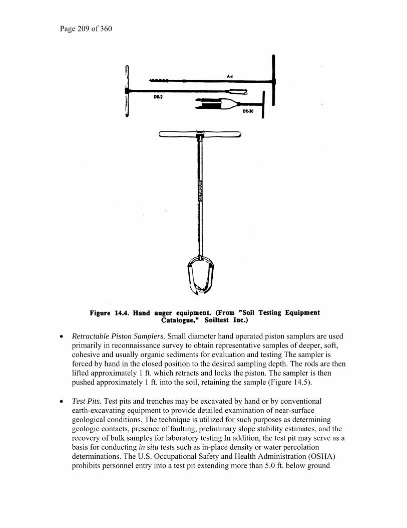
• Hand augers. A variety of hand augers or post hole diggers may be used in obtaining
representative samples of the near surface soil conditions. A variety of sizes and styles of cutter heads are available and extensions may be added for greater penetration depths (Figure 14.4). Small gasoline engine powered hand augers will increase depth penetration and decrease the difficulty of performing the work.
Page 209 of 360
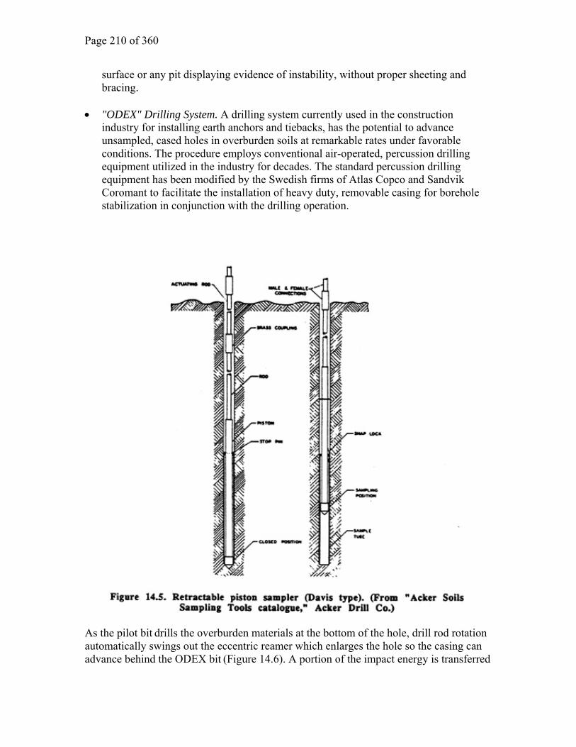
• Retractable Piston Samplers. Small diameter hand operated piston samplers are used primarily in reconnaissance survey to obtain representative samples of deeper, soft, cohesive and usually organic sediments for evaluation and testing The sampler is forced by hand in the closed position to the desired sampling depth. The rods are then lifted approximately 1 ft. which retracts and locks the piston. The sampler is then pushed approximately 1 ft. into the soil, retaining the sample (Figure 14.5).
• Test Pits. Test pits and trenches may be excavated by hand or by conventional
earth-excavating equipment to provide detailed examination of near-surface geological conditions. The technique is utilized for such purposes as determining geologic contacts, presence of faulting, preliminary slope stability estimates, and the recovery of bulk samples for laboratory testing In addition, the test pit may serve as a basis for conducting in situ tests such as in-place density or water percolation determinations. The U.S. Occupational Safety and Health Administration (OSHA) prohibits personnel entry into a test pit extending more than 5.0 ft. below ground
Page 210 of 360
surface or any pit displaying evidence of instability, without proper sheeting and bracing.
• "ODEX" Drilling System. A drilling system currently used in the construction
industry for installing earth anchors and tiebacks, has the potential to advance unsampled, cased holes in overburden soils at remarkable rates under favorable conditions. The procedure employs conventional air-operated, percussion drilling equipment utilized in the industry for decades. The standard percussion drilling equipment has been modified by the Swedish firms of Atlas Copco and Sandvik Coromant to facilitate the installation of heavy duty, removable casing for borehole stabilization in conjunction with the drilling operation.
As the pilot bit drills the overburden materials at the bottom of the hole, drill rod rotation automatically swings out the eccentric reamer which enlarges the hole so the casing can advance behind the ODEX bit (Figure 14.6). A portion of the impact energy is transferred

Page 211 of 360
from the rock drill by way of a shank adapter to a driving cap above the casing which is advanced without rotation. When the drilling is completed, the drill bit is rotated in the opposite direction, aligning the eccentric reamer with the drill bit. This allows the drill tools to be withdrawn into the casing (Figure 14.7). If the ODEX bole has penetrated into solid rock, drilling can continue with conventional equipment through the casing tube. Inexpensive, smaller diameter plastic casing may be lowered through the temporary heavy duty steel casing, which is removed after completion of the drilling, for future monitoring and instrumentation installation purposes. As with any drilling system, there are inherent limitations with the technique and driller expertise is essential. Horizontal Drilling Systems. Drilling equipment which is specially designed for installing horizontal drains and tiebacks may be used for determining general soil conditions in embankments or vertical faces where accessibility might prevent vertical borings. Conventional sampling is very difficult or impractical using this technique, but various rotary sampling devices could be adapted to obtain samples, if required.

Page 212 of 360
Long distance horizontal borehole drilling techniques are in various stages of development as potential alternatives to vertical borings for underground structures. Horizontal alignment drilling could provide valuable information at locations where the geological structure is primarily vertical and the proposed excavation extends very deep underground, or in heavily developed urban areas where surface access and disruption would be a major consideration. As with any newly developing technique, difficulties remain; these include direction control, penetration rates, lack of experienced drillers, and lack of equipment designed to perform the work. At present, the major disadvantage of horizontal drilling is the excessive cost, which, in part, is due to its low demand as a viable exploration tool. Underwater Drilling Equipment. Subsurface explorations which are located within bodies of water are usually conducted from the surface, employing floating rafts or barges supporting conventional drilling equipment, which are anchored into position. Special "jack-up" drilling platforms are also available if the surface conditions are such that stability of the floating equipment cannot be maintained for drilling purposes. Consideration may also be given to specially designed underwater hydraulic drill rigs which are set on the bottom from support vessels and operated by driller-divers. Samples may be obtained by rotary, vibratory or gravity coring procedures and in situ testing such as penetrometer and vane shear may be conducted. Although these underwater drill rigs are usually associated with deep ocean area investigations, their use may be advantageous for a specific site situation. SOIL SAMPLING

Page 213 of 360
Once the selection of the test boring methodology has been determined based on the anticipated subsurface geological conditions, the types of soil samples required for engineering analysis and their method of recovery is selected. The numerous sampling devices based on the type of sample they are capable of obtaining, are divided into two broad categories:
• Disturbed samples
• Undisturbed samples A disturbed sample is a representative sample of a selected geological unit which has undergone structural alteration or contamination by the sampling operation. These types of samples are used for classification purposes and are obtained primarily by "open drive" samplers. Borehole cuttings and other displacement type samples would also be classified as "disturbed," but only semi-representative. Undisturbed samples are those which have been obtained by methods which minimize disturbance and are suitable for laboratory performance tests. A completely undisturbed sample cannot be obtained with present technology, and any undisturbed sample may become "disturbed" during subsequent handling or transportation. 14.10. "Wash" Sampling The most basic and generally not representative sampling method consists of recovering borehole cuttings from a variety of drilling procedures for examination and classification. The borehole cuttings will give only a general picture of the subsurface conditions, but intermixing of the various strata may lead to erroneous interpretations. Borehole cuttings will furnish supplemental information between conventional sample locations and should be closely monitored during penetration of the borehole. 14.11. Split-Barrel or Split-Spoon Open Drive Sampling The open drive "split-spoon" sampler and its associated Standard Penetration Test (SPT) is the primary method of obtaining representative samples for foundation analysis. The split-spoon, which is cut into two longitudinal sections, is driven into the soil at the bottom of the borehole. The recovered sample is removed for classification and preservation in the event that additional reference or laboratory testing is required. The split-spoon sampler is available in a variety of sizes and lengths. Various baskets, sleeves, or "trap doors" can be added to the sampler to assist in the retention of the sample during the recovery process. Split-spoon samplers should be equipped at the top with a reliable check valve and should have a minimum inside sampling length of 1.5 ft. A recovery of less than 1 ft. is generally

Page 214 of 360
not considered as an acceptable sample in fine "rained or cohesive soils. A second sample may be necessary immediately below the unsuccessful recovery. Split-spoon drive samples should be obtained at or near the ground surface, at the beginning of every change of stratum, and at those intervals required by organization policy. At the sampling points, advancement of the bore hole should be stopped. Casing, if used, should be advanced as required, but only to a depth no greater than the maximum depth of jetting and chopping or drilling, and all of the material should be removed from inside the casing or borehole. When the driven casing method is used, water is generally employed to clean out the casing before sampling, and side discharge bits are used for such cleaning. A variety of methods and equipment for obtaining the measure of penetration resistance have been standardized (ASTM D-1586; AASHTO T-206). The Standard Penetration Test (SPT consists of counting the number of blows required to drive a 2-in O.D. x 1.38-in LD. split-spoon sampler a distance of 1.5 ft with a 140 lb hammer free falling 2.5 ft. The sampler is usually driven a total of 1.5 ft and the blows are recorded per 6 in of penetration. The penetration resistance (N) is determined by adding the second and third 6 in. penetration resistance blow counts. A driving rate of 100 blows per 1 ft penetration is normally considered "refusal," however, this criterion may be varied depending on the desired information. In excessively dense soils where the Standard Penetration Test is not applicable, or when larger diameter samples are required, heavier drive hammers and solid sample spoons may be utilized to obtain representative samples. Heavy-duty 2.63 in N-size drill rods should be employed in obtaining drive samples in the deeper and larger diameter borings for stability during the driving operations. When the relative density of the soil is critical (such as for liquefaction studies) automatic trip hammers weighing 140 lb are comma available which ensure a 2.5 ft free-fall drop. A factor of particular importance in using borehole tests like the SPT, especially in cased boreholes, is maintaining the fluid level in the borehole near the top of the hole. Failure to do so may result in the soil at the bottom of the hole becoming unstable because of upward seepage of groundwater into the hole; and soil may actually "blow" into the casing. Measured parameters (e.g. blowcounts) may be much lower than expected because of the disturbed soil being sampled. Obtaining representative samples for engineering analysis, using open split-spoon samplers, is standard procedure in geomechanical engineering The principal advantage of the open drive samplers is their simplicity in construction and operation and their relative economy for evaluating in sire soil parameters through widely accepted empirical correlations. In addition, they recover representative specimens suitable for classification and for certain laboratory testing. However, there are limitations in the use of open drive sampling, and reasonable and careful evaluation of the data must be exercised. Its purpose is to obtain an approximate comparison of the in situ geological conditions and to provide samples for soil classification.

Page 215 of 360
14.12. Thin-Wall Tube Sampling
This method consists of pressing thin, seamless tubing into cohesive soils of soft consistency for preservation and supplemental laboratory testing. Although loose, fine "grained granular soils may be sampled with this method. Sample retention may be a problem, unless the sampler device is equipped with a piston which creates a vacuum and helps retain the sample in the tube. The thin-walled tubing, more commonly referred to as Shelby tubing from the manufacturer's trade name, may be any thin-wall tubing that is beveled to form a tapered cutting edge and drawn in slightly to reduce sample friction against the wall of tube during penetration. The tubes are usually cut in 2 - 3 ft lengths. The thin-wall tubing may be used with a variety of sampling devices to obtain representative and relatively undisturbed samples. As with any sampling device or method, variations in design, operation and ability to recover the sample is dependent upon the character of the materials being sampled. Standard guidelines for thin-wall sampling have been established in AASHTO T207 and ASTM 1587. Thin-Wall, Open-Drive Sampler. The most common and simplest method of obtaining relatively undisturbed samples consists of pressing an open, thin-walled tube into the desired stratum at the bottom of the borehole. This method does not utilize any sample retention devices, although the sampler head is equipped with a ball check valve and vents to relieve air and water pressure buildup within the tube. The thin-wall open-drive sampler, which has the advantage in its simplicity of construction and operation, also has. Several major disadvantages as follows: 1. Disturbed and intermixed soil materials from the bottom and sides of the borehole may enter the tube as it is lowered into position. 2. Penetration of the sampler under the weight of the drill rods may occur in very soft or loose materials, preventing accurate measurements for controlled sampler penetration. 3. Total or partial sample recovery is difficult without a supplemental retention system. 4. Hydrostatic pressures may disturb the sample during penetration or totally prevent the sample from entering the tube. The majority of these disadvantages may be eliminated by using one of the several varieties of the stationary piston sampler and/or the use of borehole casing to eliminate sampler contamination. Mechanical Stationary Piston Sampler. The Mechanical Stationary Piston Sampler is similar in construction to the thin-wall, open drive sampler. Several major improvements in the design of the sampler include the addition of a sealed piston and locking cone in

Page 216 of 360
the head assembly to prevent the piston from moving downward (Figure 14.8). The piston can be locked and fully sealed at the bottom of the thin-wall tube so that it can be lowered into the borehole without contamination. Once the sampler is in position, the piston, through a series of small diameter inner actuating rods, is locked to the drill rig or the casing and pressure is applied to the outer drill rods which forces the thinwall tube down from the "Stationary" piston. When the fun press is completed (24 in) any pressure buildup is released through a small hole in the actuating rods. The tight seal of the piston also creates a vacuum on the sample which aids in sample retention. The sampler is rotated two full turns to shear off the soil at the bottom of the tube and withdrawn very carefully from the borehole. A short waiting period before and after shearing allows additional skin friction to develop between the sample and the tube, which win further minimize sample loss during recovery. The Mechanical Stationary Piston Sampler is a significant improvement over the thin-wall open-drive sampler, in that it decreases sample disturbance and improves recovery. Floating Piston Sampler. The Floating Piston Sampler is generally similar in appearance to the Stationary Piston Sampler, except that the actuating rods which connect to the piston are eliminated, thus allowing the piston to "float" within the assembly. The ability of the piston to "float" is a disadvantage in soft soils and the proper use of this equipment is limited to sampling stiff or hard cohesive soils. In operation, the piston is manually set flush with the bottom of the thin-walltube. Providing that the packing between the piston and the tube is tight, the piston will remain in this position while it is lowered to sampling elevation in the borehole, providing performance similar to stationary piston sampling. As the sampling tube is pressed into the soil to be sampled, the piston moves upward relative to the tube.

Page 217 of 360
In soft cohesive soils, the force required to make the piston move along the tube may be excessive, relative to the shear strength of the soft material being sampled. Thus, the soil to be sampled may be compressed or otherwise disturbed by the sampling process, as the tube with piston in the flush position is pressed into the soil. If sufficient resistance is not provided by the material being sampled, the piston will remain in the flush position, soft soil will simply be displaced, and no sample will be obtained. Retractable Piston Sampler. The Retractable Piston Sampler is similar to the Stationary Piston Sampler in that it retains the inner rod which operates the piston. However, even though it is much simpler to operate, it loses many of the advantages of the Stationary Piston Sampler. The sampler, with the piston at the bottom of the tube to prevent materials from entering the sampler, is lowered to the bottom of the borehole. The piston is then partially retracted into the tube and locked in place. This is accomplished by a series of extension rods connected to the surface. The sampler assembly is pressed into the soil and the piston is then fully retracted which closes the vents in the head assembly preventing hydrostatic pressures Tom forcing the

Page 218 of 360
sample out of the tube during subsequent recovery. Although the assembly and sampling operations are similar to the Stationary Piston Sampler, the tight seals obtained with the packer system of the stationary sampler cannot be duplicated with the Retractable system. There is a tendency for soil and fluids to pass around the piston into the sample chamber creating excess pressures which jam the piston and allows only the recovery of the disturbed materials. In addition, the vacuum created during penetration with the Stationary Piston Sampler which improves recovery, is not possible with this procedure. Hydraulic/Pneumatic (Osterberg) Piston Sampler. The hydraulic Piston Sampler is designed to obtain undisturbed samples of soft and potentially sensitive soils in uncased boreholes. The design of the sampler varies considerably from the Stationary Piston Sampler, in that it consists of an inner thin-wall sampler tube and outer pressure cylinder. In the sampling position, a movable piston is attached to the top of the sampling tube and a stationary piston rests on the soil to be sampled. The sampler is activated by pumping fluids or gas through the pressure cylinder, which drives the upper piston and sampling tube down over the lower piston into the soil a fixed distance (Figure 14.9). Then the piston is withdrawn with the sample Mom the borehole. The Osterberg is adaptable to both 3.0 in and 5.0 in diameter, thin wall sampling tubes.
The self contained and very portable aspects of the Hydraulic/Pneumatic Piston Sampler make it an ideal sampling device in swamps and areas of difficult access for large, conventional drilling equipment. Bishop Sand Sampler. The Bishop Sand Sampler utilizes both mechanical and pneumatic methods for recovering loose, saturated sands below the water table.

Page 219 of 360
The Bishop sampler consists of an inner thin-wall sampler tube and outer pressure cylinder. The sampler is pressed into the soil by conventional mechanical methods. Compressed air is then pumped through a specially designed head assembly which forces water from the outer cylinder and closes the pressure relief valves in the sampler. The sampler tube is then retracted into the outer cylinder and the entire unit is removed from the borehole Swedish Foil Sampler. A method to obtain long continuous undisturbed samples and minimize sable skin action disturbance during sampler penetration was developed by the Royal Swedish Geotechnical Institute. Although this procedure has not met with wide acceptance in the United States its potential advantages in obtaining undisturbed samples should be considered. Continuous undisturbed samples up to 60 ft in length have been obtained using this method. The foil sampler utilizes a lockable piston technique and the steel tube assembly has been modified to accommodate a chamber which contains up to 70 ft of steel foil coiled in strips. Each steel foil strip is approximately 0.43 in wide and may vary in thickness from 0.0025 to 0.008 in. As the sampler is pressed into the soil, the steel coils unroll and axially encase the sample as it enters the tube so that there is no relative movement between the sample and the foil. The inner sample tube sections, which are usually 10 ft in length, are added to the string for the desired penetration depth. The sampler is removed from the borehole by uncoupling the sections and cutting the liner at the desired lengths and sealing the ends, or the sample can be easily removed in the field for observation by pulling on the steel foil. As with any sampling system, there are limitations to the procedure; however, recent refinements in the equipment and technique have overcome many of the objections. These include automatic sample retainers, advancing the sampler by jetting with water or mud; and the application of rotary core barrel techniques to facilitate deeper and easier penetration. 14.13. Rotary Core Barrel Sampling A variety of core barrels, which were originally developed for drilling and sampling bedrock, have been modified or adapted to obtain "undisturbed" overburden samples in very dense or partially cemented soils. These core barrels are used when the more conventional thin-wall samplers cannot penetrate the selected geological unit. There are many local variations in the type and mechanics of these core barrels which are commercially available under a variety of trade names. Single wall or single tube core barrels equipped with saw-tooth cutter bits have been used to some extent in sampling soils. However, the samples are usually disturbed by

Page 220 of 360
intermixing, swelling or contamination with drilling fluid. Core barrels equipped with non-rotating innerliners are more suitable for overburden sampling and several varieties are discussed in the following sections. Dennison Sampler. The Denison Sampler is designed to recover undisturbed, thin-wall samples in dense sand/gravel soils, hard clays, partially cemented soils or soft and weathered rock. The sampler consists of a double-tube, swivel-type core barrel with a non-rotating inner thinwall steel or brass liner designed to retain the sample during penetration and subsequent transportation to the laboratory. The inner liner tube of the Denison has a sharp cutting edge which can be varied to extend from zero to about 3 in. beyond die outer rotating cutter bit. The amount of extension can be varied by means of interchangeable saw tooth cutter bits which are preselected depending on the anticipated formation which is to be sampled The maximum extension is used in relatively soft or loose soils and a cutting edge flush with the coring bit is used in hard or cemented formations. An important feature of the Denison Sampler is a system of check valves and release vents which by-pass the hydrostatic pressure buildup within the inner sampling tube, improving sample recovery and minimizing pressure disturbance of the sample. The Denison Sampler is rotated into the formation in the same manner as conventional rock coring procedures, in either a cased or mudded borehole. The Sampler is designed for use with water, mud or air and is available in five sizes, ranging from 2 .94 in. to 7.75-in. O.D. The Denison Sampler is not a practical tool for sampling loose sands or soft clays, as the sample retention devices are usually inadequate for these materials. The presence of cobbles and boulders will present major difficulties for penetration and recovery. The saw-tooth bit, with which the Denison is usually equipped, is not capable of coring hard boulders which may cause collapse of the inner sampler tube if it is in an extended position. Pitcher Sampler. The Pitcher Rotary Core Barrel Sampler is a modification of the Denison sampler. The Pitcher Sampler was developed to recover undisturbed thin-wall samples in formations which are too dense for conventional thin-wall sampler penetration. The Pitcher Sampler consists of a single tube, swivel-type core barrel with a self-adjusting, spring-loaded inner t7nin-wall sample tube which telescopes in and out of the cutter bit as the hardness of the material varies. This telescoping aspect eliminates the need to pre-select a fixed inner barrel shoe length as with the Denison Sampler.

Page 221 of 360
The inner steel or brass thin-wall liner tube has a sharp cutting edge which projects a maximum of 0.5 ft beyond the saw-tooth cutter bit in its normal assembled position. As the sampler enters the borehole, a sliding valve directs the drilling fluid through the thin-wall sample tube for a thorough preflushing of the borehole. When the sample tube comes in contact with the bottom of the borehole, it telescopes into the cutter barrel and closes the sliding valve which diverts the drilling fluid to an annular space between the sample tube and the cutter barrel. This sliding valve arrangement allows the circulation of the drilling fluid to remove the borehole cuttings during sampling and prevents disturbance of the recovered crumple by the drilling fluid. The spring-loaded inner sample tube automatically adjusts to the density of the formation being penetrated. In very soft materials, it will extend as much as 0.5 ft. beyond the cutter bit and as the formation density increases, the sample tube telescopes into the outer core barrel and compresses the control spring, which, in turn, exerts a greater force on the tube to insure adequate penetration. In extremely dense formations or obstructions, the sample tube will retract completely into the outer core barrel to allow the cutter bit to penetrate the obstruction. The Pitcher Sampler is also rotated into the formation in the same manner as conventional rock coring procedures in either a cased or mudded borehole. The sampler is designed for use with either water or mud and is available in four sizes, ranging from 2.5 in. to 5.875-in. O.D. A schematic drawing of the Pitcher Sampler operation is shown on Figure 14.10. The telescoping liner aspect of the Pitcher Sampler is a major advantage in highly variable formations, which prevents collapse of the sample tube. However, the Pitcher Sampler, like the Denison, is not capable of coring very competent cobbles and boulders.

Page 222 of 360
Triple Tube Conversion Core Barrel Sampler. Recent modifications and improvements in conventional rock drilling core barrels allow interchangeable conversions from rock coring barrels to soil coring units. These core barrels, utilizing basic rock coring barrel design, combine the principles of the Denison or the Pitcher sampler. In addition, a third inner liner which retains the sample further minimizes sample disturbance and improves recovery. 14.14. Block Sampling One of the oldest, and considered by many as the most reliable, methods of obtaining undisturbed samples for laboratory testing, consists of cutting large blocks of soil from the natural, in situ formations. Although tests samples are usually obtained from sediments which display cohesion, either real or apparent, there are instances where granular soils have been satisfactorily obtained by lowering the water table in the sample area A test pit or shaft is excavated to the desired sample location and the soil is cut by hand in the shape of a projecting cube. The cube should be approximately 2 in. smaller in all dimensions than a wooden box in which the sample is to be encased for transport. The box should be constructed so that the top and bottom panels may be easily removed or replaced in the field. Several layers of cheesecloth are carefully placed to avoid damage to the cube corners and edges. Melted microcrystalline wax is poured first into the bottom of the box. The sample is then placed, in a centered position into the box and wax is poured between the sample and the box and allowed to harden. Wax is then added to the top of the sample and the cover is attached. The bottom of the sample is then cut away from the ground and the box containing the sample, is reversed. Cheesecloth wax and cover are added to the bottom of the box, completing the sampling and preservation of the block sample. 14.15. ROCK CORM SAMPLING The primary objective of rock core sampling is to obtain continuous, undisturbed cores in the intact rock mass for evaluation of characteristics which may affect its performance as in excavations or as a construction material. These characteristics include the following:
• Elevation
• Lithology
• Weathering

Page 223 of 360
• Hardness
• Structure
• Permeability
• Discontinuities
• Mineralogy The rock core samples which are recovered can be further evaluated in the laboratory for such additional engineering preppies as compressive strength, elastic modulus and abrasion resistance. The completed rock core blowhole may be tested and monitored to determine permeability, groundwater conditions, the presence of gas and squeezing or expansive properties of the rock. The borehole may be further utilized for in situ testing purposes, geophysical surveys and the installation of various types of monitoring equipment or instrumentation. Rock core sampling can provide substantial geotechnical information in the immediate vicinity of the borehole. However, rock core sampling usually provides only a limited amount of information about the overall rock mass, and this information must be extrapolated into engineering decisions for the entire formation. Careful observation and evaluation during drilling and logging of the recovered core is essential to any site investigation program. The rock coring procedures and equipment which were developed in 1863 by Leschot, a Swiss engineer, remain basically the same; a hollow steel tube equipped with a diamond bit is rotated into the rock surface. However, major improvements in the core barrels, diamond bits and associated equipment have created very sophisticated rock core sampling devices. Diamond rock drilling methods have been generally standardized by the American Society for Testing and Materials (ASTM D-2113). To facilitate standardization of equipment the Diamond Core Drill Manufactures Association (DCDMA) has established standard sizes for bits, shells and casings. The venous DCDMA size standards for core barrels and bits are summarized in Table 14.1.

Page 224 of 360
The primary purpose of any type of core barrel is to recover the total amount of rock which is physically cored, in a relatively undisturbed state. When drilling in competent rock total recovery is rarely a problem; however, when the formation is highly weathered, fractured or soft, core recovery becomes poor. The strength and behavior of the rock mess is primarily dependent upon the various inherent discontinuities; core which is not recovered may represent significant engineering implications. The selection of the most practical core barrel for the anticipated bedrock conditions is important. The selection of the correct drill bit is also essential to good recovery and drilling production. Although the final responsibility of bit selection is usually the drilling contractor's, there is a tendency in the trade to use "whatever happens to be at hand." The selection of the diamond size, bit crown contour and number of water ports is dependent upon the characteristics of the rock mass and the use of an incorrect bit can be detrimental to the overall core recovery. Generally, fewer and larger diamonds are used to core soft formations and more numerous, smaller diamonds which are mounted on the more commonly used, semi-round bit crown are used in hard formations. Special impregnated diamond core bits have been recently developed for use in severely weathered and red formations where bit abrasion can be very high. 14.16. Rotary Core Barrel Types The Rotary Core Barrel is manufactured in three basic types: single tube, double tube, and triple tube. These basic units all operate on the same principle of pumping drilling fluid through the drill rods and core barrel. This is done to cool the diamond bit during drilling and to carry the borehole cuttings to the surface. A variety of coring bits, core retainers, and liners are used in various combinations to mad the recovery and penetration rate of the selected core barrel. The simplest type of rotary core barrel is the single tube, which consists of a case hardened, hollow steel tube with a diamond drilling bit attached at the bottom. The diamond bit cuts an annular groove or kerf in the formation to allow passage of the drilling fluid and cuttings up the outside of the core barrel. However, the drilling fluid must pass over the recovered sample during drilling and the single tube core barrel cannot be employed in formations that are subject to erosion, slaking or excessive swelling. The most popular and widely used rotary core barrel is the double tube, which is basically a single tube barrel with a separate and additional inner liner and is available in either a rigid or swivel type of inner liner construction. In the rigid types, the inner liner is faxed to the outer core barrel so that it rotates with the outer tube. In contrast, the swivel type of inner liner is supported on a ball bearing carrier which allows the inner tube to remain stationary, or nearly so, during rotation of the outer barrel. The sample or core is cut by rotation of the diamond bit. The bit is in constant contact with the drilling fluid as it flushes out the borehole cuttings. The addition of bottom discharge bits and fluid control valves to the core barrel system minimizes the amount of drilling fluid and its contact with the sample which further decreases sample disturbance.
Page 225 of 360
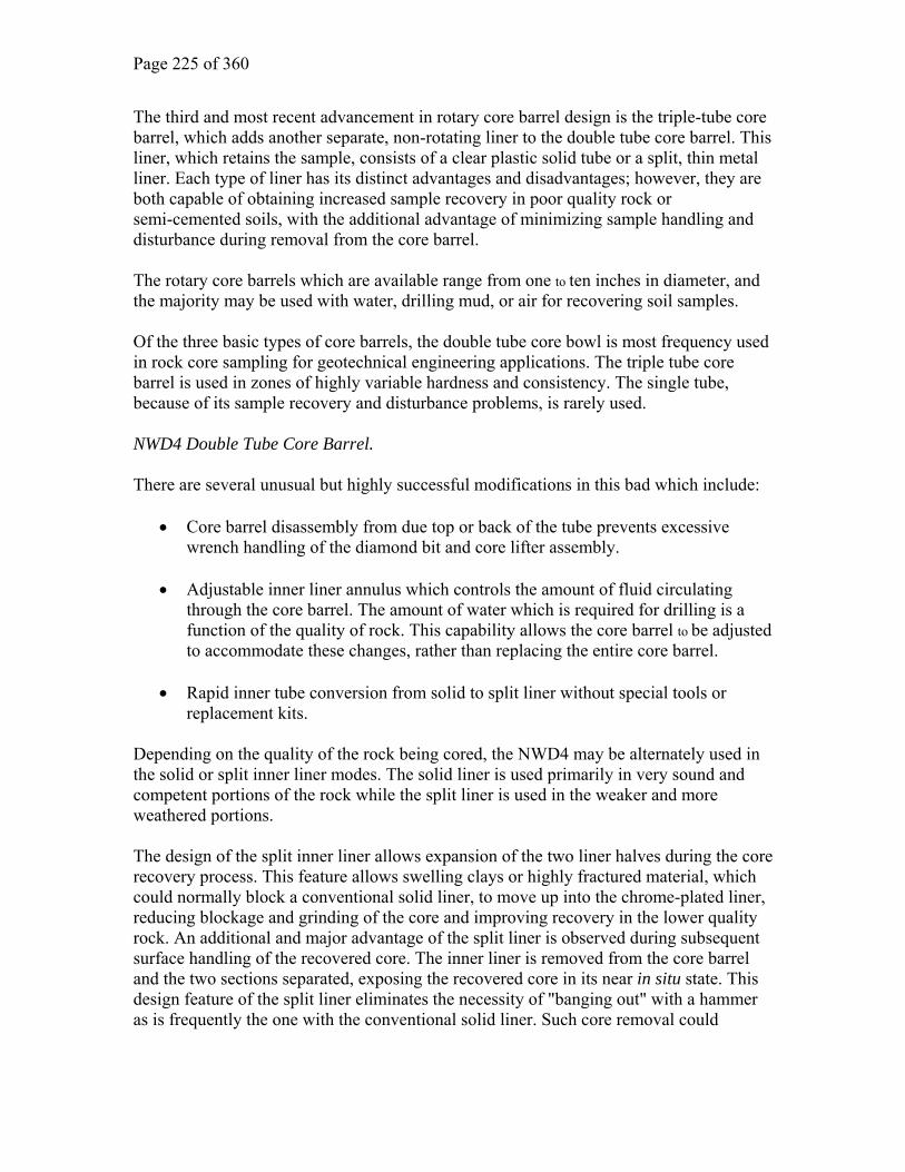
The third and most recent advancement in rotary core barrel design is the triple-tube core barrel, which adds another separate, non-rotating liner to the double tube core barrel. This liner, which retains the sample, consists of a clear plastic solid tube or a split, thin metal liner. Each type of liner has its distinct advantages and disadvantages; however, they are both capable of obtaining increased sample recovery in poor quality rock or semi-cemented soils, with the additional advantage of minimizing sample handling and disturbance during removal from the core barrel. The rotary core barrels which are available range from one to ten inches in diameter, and the majority may be used with water, drilling mud, or air for recovering soil samples. Of the three basic types of core barrels, the double tube core bowl is most frequency used in rock core sampling for geotechnical engineering applications. The triple tube core barrel is used in zones of highly variable hardness and consistency. The single tube, because of its sample recovery and disturbance problems, is rarely used. NWD4 Double Tube Core Barrel. There are several unusual but highly successful modifications in this bad which include:
• Core barrel disassembly from due top or back of the tube prevents excessive wrench handling of the diamond bit and core lifter assembly.
• Adjustable inner liner annulus which controls the amount of fluid circulating
through the core barrel. The amount of water which is required for drilling is a function of the quality of rock. This capability allows the core barrel to be adjusted to accommodate these changes, rather than replacing the entire core barrel.
• Rapid inner tube conversion from solid to split liner without special tools or
replacement kits. Depending on the quality of the rock being cored, the NWD4 may be alternately used in the solid or split inner liner modes. The solid liner is used primarily in very sound and competent portions of the rock while the split liner is used in the weaker and more weathered portions. The design of the split inner liner allows expansion of the two liner halves during the core recovery process. This feature allows swelling clays or highly fractured material, which could normally block a conventional solid liner, to move up into the chrome-plated liner, reducing blockage and grinding of the core and improving recovery in the lower quality rock. An additional and major advantage of the split liner is observed during subsequent surface handling of the recovered core. The inner liner is removed from the core barrel and the two sections separated, exposing the recovered core in its near in situ state. This design feature of the split liner eliminates the necessity of "banging out" with a hammer as is frequently the one with the conventional solid liner. Such core removal could
Page 226 of 360
severely diddle and alter the quality of the recovered core, leading to erroneous conclusions about the overall rock mass. The split inner-liner is used in a variety of types and sizes of double and triple tube core barrels. The capability of improving recovery in poor quality rock, and the subsequent surface handling advantages, makes it a valuable equipment addition for the purpose of rock core evaluation. NWM3 Triple Tube Core Barrel. The swivel-type, triple-tube core barrel is a modification of the Series M double-tube core barrel that includes an additional inner solid clear plastic liner which retains the sample recovery. The purpose of the third, non-rotating inner liner is to further improve sample recovery in soft or highly fractured rock and to provide a temporary storage container for the recovered rock core during transportation and storage. The NWM3 incorporates an adjustable inner liner which can control the flow of water to the bit, an important design feature in variable formation conditions. The use of bottom discharge bits also minimizes the amount of drilling fluid in contact with the recovered sample, decreasing the erosive action in highly decomposed rock. The NWM3 triple-tube core barrel is an important advancement in drilling technology that improves recovery in formations which are difficult to sample with conventional core barrels. A special hydraulic or pneumatic jack is required for inner tube removal and subsequent sample extraction from the inner tube. Although the solid plastic sample liner tube has definite advantages during transportation and storage, it can impede, somewhat, field examination, photographing, and evaluation of the core immediately upon recovery. 14.17. Specialty Core Barrel Types A variety of special core barrels have been developed for specific sampling problems and requirements. These core barrels may adapt conventional rotary core barrel design or utilize completely different techniques and equipment. Several of these specialty core barrels are briefly summarize below: · Wire Line or Retractable Core Barrel · Calyx or Shot Core Barrel · Steel Tooth Cutter Barrel · Percussion Core Barrel

Page 227 of 360
Wireline Core Barrel. In conventional rock coring the entire drill stem and core barrel must be removed after each core run (usually 1.5 to .5 feet). This is a time-consuming operation on deep core holes, in addition to creating an inherent risk for collapse of the rock into the unsupported borehole. The Wire Line system is designed to recover rock core without removing the drill stem from the borehole after each core run. When drilling is completed, a special latching mechanism is lowered through the drill rods at the end of a cable which attaches to the inner barrel of the sampler. The inner barrel containing the rock core, is rapidly brought to the surface, leaving the outer core barrel and drill rods sill in position within the borehole. The wireline can also be adapted for horizontal drilling and triple tube applications. Calyx or Shot Core Barrel. This method of obtaining very large diameter samples of competent rock core, derives its name from the use of chilled, hard steel shot used as the cutting medium. Single tube, heavy walled, soft steel cutter barrels of varying lengths and diameters are manufactured especially for this purpose. The steel shot is fed into the annular space between the core and core barrel and grind their way to the bottom of the hole where they are picked up in a special kerf cut into the bottom of the barrel The steel shot, which is added as the drilling progresses, wears away the rock beneath the rotating barrel. A special "Calyx" at the top of the barrel causes a reduction in the rate of the resuming wash water and serves to collect the borehole cuttings and worn-out shot. The core is removed from the borehole by special large diameter core lifers or by grouting the core inside the barrel with gravel. Considerable driller expertise is required with this method. The diameter of the core that can be recovered is limited only by the capability of the equipment to turn the core barrel and subsequently recover it. Steel Tooth Cutter Barrel. Single tube core barrels equipped with metal teeth are used for obtaining large-diameter cores in soft or seamy rock. However, any type of core barrel may be equipped with steel cutter teeth if the situation does not require the use of diamond bits. The Denison and Pitcher Samplers are generally equipped with this type of cutter bit. The steel cutter teeth may also be equipped with hard metal alloy inserts such as tungsten-carbide, to improve drilling rates. The metal inserts may be replaced in the bit very readily, renewing a dull or damaged bit for additional drilling. The steel tooth cutter barrels are operated in the same manner as conventional rotary core barrels except that they are rotated at much slower speeds. As the costs associated with these types of bits are considerably less than costs for bits equipped with diamonds, they are used in areas of difficult drilling where bit loss may be appreciable. These areas would include the drilling of structural steel in concrete or dry hole drilling which would burn up and destroy diamond bits very rapidly. Percussion Core Barrel. The percussion or cable tool core barrel is more widely used In the soil and water well industry and not commonly associated with foundation investigations. This core barrel consists of an outer barrel with a hardened steel bit and an
Page 228 of 360
inner barrel equipped with a pressure release system and core retainer. The inner barrel remains in contact with the rock and slides down over the core as the surrounding material is cut away by raising and dropping the outer barrel. Cores can be obtained in materials ranging from partially cemented soils to medium-hard rock. However, some disturbance and breakage of the core usually occurs during the dynamic sampling process. 14.18. Integral Rock Core Sampling The determination of the various bedrock discontinuities which effect the strength and stability of a rock mass, are of critical importance in the design and construction of underground openings in rock. The structural integrity of the rock mass is affected by the presence and orientation of such features as bedding, jointing and faulting, and also by the spacing, continuity, planarity and infilling of these discontinuities. The primary method for evaluating the geotechnical parameters relies upon measurements and observations of exposed bedrock in the area of the proposed construction. These outcrops may or may not reflect the actual in situ conditions of the bedrock unit at depth. In urban areas, bedrock outcrops may be very limited and far removed from the actual area of construction. Typical subsurface exploration programs, which are initiated to obtain information about the structural defects of the bedrock, may lack the detail required for a reasonable assessment of these characteristics. Grinding of the rock core, poor recovery and washing out of the gouge and infillings during the drilling operation create erroneous conclusions regarding the quality of the in situ rock mass. In addition, conventional exploration methods are not capable of determining the orientation of the overall bedrock structure or the discontinuities. Several subsurface exploration methods recently developed are capable of obtaining the structural orientation of the planar features of the in situ bedrock. These rock core orienting methods are combined with conventional diamond core drilling and are not capable of recovering totally intact, undisturbed, continuous samples of the bedrock. Techniques which combine total intact core recovery, and structural orientation are discussed next. LNEC Irntegral Sampling Method (ISM). A method that combines structural orientation with total in act rock sample recovery is the "Integral Sampling Method" (ISM). This relatively new and sophisticated technique of injecting grout into a small diameter pilot hole, orienting the grout rods to a surface feature and then overcoming the solidified mass with a larger diameter core barrel is used for detailed structural and engineering analysis of the in situ rock mass. This expensive but very valuable subsurface exploration technique will provide detailed information about the in situ rock mass properties which cannot be obtained by other conventional methods.

Page 229 of 360
A conventional cased borehole with the required inclination is drilled to the depth where structural information on the bedrock unit is desired. The ISM core can then be recovered in NX (3 in) and HX (3.875 in) sizes, depending on the anticipated quality of the bedrock The recovery of the ISM core sample is achieved in three basic operational Phase I A stabilizing guide assembly, having an outside diameter slightly less than the diameter of the borehole, is installed at the bottom of the hole. A small diameter pilot hole, approximately 1.25 in. diameter, is drilled into the intact rock below the stabilizing guide assembly with an RWT size coring or non-coring diamond bit. The stabilizing assembly maintains the pilot hole in coaxial alignment with the primary borehole (Figure 14.11). When the pilot hole is completed, the pilot drill and stabilizing assembly is removed from the borehole.
Phase II A second stabilizing guide assembly, which incorporates a detachable grout/reinforcing/orienting, or "GRO" tube. This perforated, steel reinforcing tube, is lowered into the borehole so that the GRO tube extends into the predrilled RWT pilot hole. The GRO tube is connected to the surface with a string of interlocking, aligned, hollow orienting rods. A special orienting device is attached to the orienting rods and

Page 230 of 360
visually aligned with a permanent landmark whose directional bearing from the borehole may be determined at a later date. A predetermined amount of cement or chemical grout is then injected through the orienting rods and GRO tube into the voids and fractures around the pilot hole. After the grout is allowed to solidify, the GRO assembly is sheared off above the grout rod and recovered from the borehole (Figure 14.12). Phase III The solidified grout bonds the fractured rock to the oriented GRO reinforcing rod and the entire installation is overcored with a conventional core barrel, usually of the same diameter as the basic borehole (Figure 14.13). A variety of core barrels are suitable for the overcoming phase, although one equipped with a split inner liner is preferred. The core barrel is retrieved in the normal manner and the intact integral rock sample is evaluated for structural defects. CSIR Integral Sampling Method. This integral sampling technique follows the same basic procedures developed by LNEC. However, there are several major differences in the equipment and specific methods relating to the insertion of the grout medium and the use of plastic (PVC) grout/ reinforcing/orienting rods.
A reinforcing rod manufactured from PVC is used in order to preclude damage to the drill bit in case any eccentricity occurs during the overcoring process. A resin-filled

Page 231 of 360
cartridge is attached to the reinforcing rod, eliminating the need for surface grout reservoirs and pumps. The resin cartridge is manufactured from commercially available PVC tubing and a wooden plunger. The system is manually operated at ground surface and displaces the resin through randomly drilled holes in the PVC grout rod. A saw cut groove along the long axis of the PVC is used for orienting the core in the same manner as the LNEC method. ISM Application Considerations. As with any newly developed methodology, continued application and familiarization with the equipment and technical procedures will lead to improvements and modifications in the technique. The present high costs of ISM drilling are due primarily to lack of expertise with the procedure. Several minor deficiencies exist in the application of the ISM technique at its current state-of-the-art, which should be evaluated prior to selecting this system for a particular project. These include:
• Required training of the drilling crew unfamiliar with the procedure by qualified ISM technicians under actual field conditions.
• A trial and error phase by the drilling crew, even after field training.
• Limitations of the procedure in highly-fractured, open-jointed rock.
Highly-fractured rock tends to collapse into the pilot borehole preventing re-entry of the grout rods, or the grout tends to flow beyond the limits of the overcoring phase.
• Modifications of the grout tube would provide total grout distribution into the
desired areas.
• The selection of the proper grout for the specific situation requires considerable field experience.

Page 232 of 360
14.19. Rock Structure Orientation Methods The determination of the true attitudes of planar structural discontinuities of rock encountered during subsurface explorations may be accomplished in either of two ways; by measuring the azimuth and dip of the discontinuities recorded on the physical core recovered; or by determining the orientation of the structural features from their presence on the borehole wall. If rock core or impressions of the wall of a borehole can be oriented with respect to a feature of known Section, whether a scribed line on the core, a geologic feature of fixed orientation or alignment of the recording device in a known attitude, it is possible to measure the true dip and strike Sections of all geological features in the borehole. These determinations consist of simple measurements; however, mathematical or graphical stereo plots are required if the borehole varies from the vertical or horizontal position. Various methods, ranging from simple to complex, have been developed to establish a reference point of known orientation so that all structural aspects of the borehole may be related to it and their absolute orientations determined The Integral Sampling Method discussed is one of the more complex methods of achieving structural orientation of the in situ rock and total rock core recovery. The majority of the methods combine conventional rotary rock drilling equipment with specialized core barrels which mark the core so that it can be subsequently oriented using geological interpretive methods. 14.19.1. Structural orientation methods which are applied from within the completed borehole. The variety of rock core orientation methods and equipment are summarized below:

Page 233 of 360
Physical Core Alignment Methods. These alignment methods all require a constant and known structural azimuth which may be used for determining the orientation relationship of other discontinuities to the known azimuth. Complex rock structure with varying features are not suitable for physical core alignment methods. In addition, these methods all retain inherent limitations in their procedure or equipment. Their major asset is the relative simplicity and low cost to conduct. · Physical Alignment: the most simple and effective method, if core recovery is excellent, is to match the various core stems which are recovered so that they are in their original borehole alignment. A reference line is then drawn along the entire core and its orientation is determined from the structural feature with a known azimuth. The remaining discontinuities are then related to the reference line. · Paint and Acid Markers: a relatively simple method, which can only be used in inclined boreholes, consists of breaking a container of paint against the rock surface at the bottom of the borehole. The paint runs down the core stub which gives a reasonably accurate indication of the underside of the core stem. Once the core is removed, it may be physically aligned and a reference line established. A tube of hydrofluoric acid may also be broken against the core stub at the base of the borehole, which etches the rock surface at the bottom of the core. · Craelius Core Orientator: This relatively simple mechanical device used in inclined boreholes, "floats" within a conventional core barrel and consists of six, self-locking prongs which adjust to the profile of the core stub at the base of the borehole. The profiling prongs are locked into position when pressure is applied to a spring loaded plunger mounted behind the prongs. As the rock is being cored, the orientator slides back into the core barrel. When extracted, the core is placed in a cradle and rotated until the face conforms with the profiling pins. The remaining core segments are then aligned by mating opposing discontinuity surfaces. Orienting Core Barrels. Specialized core barrels have been recently developed which scribe a reference mark on the core as it is drilled. Special recording devices within the core barrel relate known azimuth orientations to the reference mark so that when the core is subsequently removed from the core barrel, it can be oriented to the exact position it occupied in situ. These specialized core barrels are relatively expensive and require highly trained personnel to operate them and to interpret the results. In addition, several limitations are inherent with these devices: · Excellent recovery is required for quality interpretation. · Will not function in strong magnetic environments.

Page 234 of 360
· Steeply inclined boreholes will interfere with the compass unit. The individual orienting core barrels now available are as follows: · BHP Orienting Core Barrel: The BHP core barrel utilizes a compass and chart recording system which aligns itself with a scribing diamond. As the core passes the drill bit into the inner liner, a reference line of known orientation is scribed on the rock core. · Christensen-Hugel Orienting Core Barrel: The C-H core barrel operates in a similar manner to that of the BHP barrel. Incorporated within the core barrel is an Eastman Multishot directional survey instrument which photographically records the compass bearing and plunge of the borehole. In addition, it records the orientation of reference grooves which are cut into the core as it enters the barrel. The developed film is evaluated in a special read-out unit which synchronizes the correct photograph of the compass with depth. This information will supply the true bearing of the main scribe, the true inclination of the borehole and the true dip direction of the borehole. This information is then preset on a special readout unit referred to as a goniometer and the various sections of rock core can be evaluated for structure and discontinuities and their orientation determined. 14.20. EXPLORATION DIFFICULTIES Specific advantages and disadvantages of the various subsurface exploration techniques and equipment have been discussed within the preceding sections. However, limitations and difficulties may be encountered during the exploration programs which are common to all exploration techniques. These are usually a result of site specific geological conditions and not necessarily a function of the equipment or method being used. 14.20.1. Sample Recovery Generally, sample recovery less than l ft. is considered inadequate for representative sampling. However, this criteria may be waived for the specific situation (i.e.: in thick, uniform deposits, recovery considerably less than l ft. may be acceptable). The use of drilling mud with its greater specific gravity and viscosity will assist in sample retention. Various sampling devices equipped with check and pressure release valves, sample retaining springs, baskets and lifters should be used or determined to be operational. Occasionally, drillers will modify equipment to meet their specific drilling technique, which may have major effects on sample recovery. Selective overdriving of the sampling device will jam excess material into the sampler tending to retain the sample within the device during recovery. However, this procedure can only be used where disturbed samples are acceptable. 14.20.2. Sample Disturbance

Page 235 of 360
Using existing soil sampling techniques, there is no way to obtain a truly "undisturbed" sample. Block sampling continues to be the most reliable method for minimizing sample disturbance and is used for comparison testing between other sampling techniques. However, obtaining block samples of the desired stratum may present major logistic problems, especially in urban areas. The Swedish Foil Sampler is another attempt to modify equipment to further minimize disturbance. Basically, the larger the diameter of the sample, the less the sample disturbance is minimized. In the case of thin-wall tube sampling, disturbance was also found to vary throughout the length of the tube. The material located near the center of the tube (assuming 2 ft. recovery) was found to be disturbed less than material at either end. The selection of the correct sampling tool, drilling technique, and borehole stabilization method will minimize sample disturbance, but additional investigations are needed to further evaluate sample disturbance and its effects. The incorrect preservation and shipment of samples may further disturb the specimens. 14.20.3. Obstructions The termination of an exploration above the required design depth due to excessively dense materials, obstructions or "refusals" may occur during any investigation. When this occurs, it usually implies that the correct exploration method was not selected for the anticipated subsurface conditions. Socialized tools and equipment are available to increase the capacity of conventional drilling equipment. This includes the use of diamond bit equipped casing which is drilled into the formation, rather than driven. A variety of drill bits are capable of drilling obstructions. 14.21. Specific Geologic Problem Conditions The preceding sections have described the various methods, equipment and limitations of obtaining representative and undistributed samples for engineering analysis. The following summarizes a variety of geologic problems affecting geotechnical exploration and design.
• Organic Soils
• Normally Consolidated Clays

Page 236 of 360
• Metastable Soils (loess, alluvial deposits & mud flows)
• Caliche
• Expansive Soils or Rocks
• Loose, Granular Soils
• Sensitive Clays
• Noxious or Explosive Gases
• Slope Movements
• Kettle Holes
• Meander Loops & Cutoffs
• Artificial Fill
• Karst (Sinkhole) Regions
• Weathered Shale Rocks
• Abandoned Mined Areas
• Frozen Soils
Other geologically-oriented foundation problems may be expected in different physiographic regions. 14.22. Groundwater Conditions In many instances, one of the major concerns in a site investigation may be the determination of the ground water conditions and general hydrogeologic regime of the site area. The location of the groundwater table, perched or artesian conditions, surface runoff end recharge are a few of the important items that must be determined during the exploration program. There is a tendency by the drillers who are conducting the work to obtain a borehole water reading during or immediately upon completion of the exploration; this water level is assumed to be the "groundwater table." As the effects of the drilling operation, especially if drilling fluids were used, generally have not dissipated, these short term water readings should be considered suspect. A reading node 24 hours after completion

Page 237 of 360
of the borehole is much preferred but in some instances, depending on the permeability of the soils, may still not be sufficient. The installation of permanent or temporary observation wells in the completed boreholes is generally an inexpensive safeguard against erroneous assumptions regarding the presence and behavior of the groundwater conditions. 14.23. Borehole Sealing Although unsealed, completed boreholes may be satisfactory at some locations, especially in rock, they may be the source of difficulties at a later date or during construction. A borehole which is not properly backfilled or sealed may provide access for unanticipated amounts of water into areas which were considered "impermeable." In addition, breached aquicludes and artesian zones may have adverse effects on the local aquifer conditions, unless properly sealed. 14.24. Preservation and Shipment Samples of soil and rock are obtained for classification and subsequent testing and analysis to determine their various engineering properties. Rock and soil samples (core, jar, can, tube and bag) represent essential physical information concerning the subject site, generally obtained under costly circumstances. Samples must be preserved, stored, and shipped under conditions that will minimize chances of disturbance or loss. All soil samples and rock cores must be clearly, accurately, and permanency labeled to show all pertinent information which may be necessary in identifying the sample or core and in determining the character of the subsurface condition. The preserving, protecting and transporting of samples may be accomplished using the methods set forth in this section, but any method which satisfactorily protects a sample intended for laboratory testing from shock, detrimental temperature changes (such as freezing), and moisture loss may be used. · All samples should be collected from the borehole sampling sites on a daily basis and transported to the field project of flee or a suitable alternate location. · Rock core and thin-wall tube soil samples should never be transported away from the field site in other than specially constructed wood, metal, plastic or fiberglass shipping containers and should be packed in excelsior or equal material in order to protect them from vibration. These containers must be secured (screws, banding, clasps, etc.) whenever they are to be transported. · Samples should not be left unattended in vehicles and any sample which is permitted to freeze, even partially, should be replaced. · Samples intended for laboratory testing should not be held at the site in excess of one week.

Page 238 of 360
· All containers should be identified as to borehole, depth interval, box number of total sequence, and project number. These markings will be placed on the exterior and interior of lids, on both ends (to facilitate identification in storage). · Any special actions taken on the samples should be identified on the interior of box lids, e.g. sampling thin-sections, x-ray diffraction, paleontological analysis, paleomagnetic measurements and radiometric age determination. · It may be advantageous, for future record purposes, to photograph the samples, particularly rock core with color film prior to packing and shipment. 14.24.1. Jar Samples Representative specimens of each sample should be preserved. The containers for preserving drive samples should be large mouth, round, screwed top, airtight, plastic or clear glass jars of sufficient size to store at least a 4 in. long section of full diameter sample. Project requirements may dictate total sample preservation and larger jars. The specimen should be placed in the jar as soon as taken in carder to preserve the original moisture in the material. The mouth of the jar should be cleaned of all dirt and grit in order to obtain an airtight seal with the screwed top. · Remove the sample carefully from the sampler and place it in the jar with a minimum amount of disturbance. Do not attempt to overfill or force excess material into the jar. · Tightly cap the jar and mark the lid with the following information:
• Project Number • Boring Number • Sample Number • Sample Depth Range • Blow Counts
Additional information may be required or desirable, which is usually added by the contractor or his supervisor at a later date in the form of a label which is affixed to the jar. · If long term preservation or additional testing is required, seal the top of the jars with plastic electrical tape and/or a non-shrinking wax. · Jars should be packed sequentially in partitioned, heavy-duty, cardboard boxes and be protected from freezing or excessive heat. · Completed boxes are generally transported to the drilling firm for additional classification and labeling · Handle and transport the sample boxes with care to avoid breakage.
Page 239 of 360
· If the samples are to be shipped by commercial or public carriers, the addition of shredded packing material (paper or plastic) around the jars will be required. · Label the box exterior, stamp with FRAGILE and THIS END UP; insure the shipment. 14.24.2. Thin-Wall Tubes Thin-wall tube sampling is utilized to obtain undisturbed cohesive and granular soils for laboratory testing. 14.24.2.1. Cohesive Samples
• Remove the thin-wall tube from the head assembly, taking care not to disturb the sample. Remove any disturbed "washings" from the top of the tube and measure the amount of sample recovered, in inches.
• Seal the top of the sample by pouring in slowly 1-2 in. of melted microcrystalline
wax in thin layers. Fill the remaining void space in the tube with packing material to prevent slippage of the sample. Special expandable O-ring packer seals may be used in lieu of wax.
• Cap the end, tape securely, and dip the end into the melted wax several times.
• Repeat steps two and three, above, for the opposite end of the tube. It may be
necessary to scrape out approximately 1 in of undisturbed material to allow space for the wax to set.
• Mark the top and bottom of the tube, the project number, boring number, sample
number, depth range, recovery and method employed in advancing the tube.
• Samples should be maintained in as near vertical position as possible and protected against excesses in heat or cold.
• Transport the samples by private vehicle whenever possible, and maintain them in
a vertical position, either by tying to the seat of the vehicle or in a rack specially constructed for transportation of undisturbed tubes.
14.24.2.2. Granular Samples
• Remove the sampler from the borehole with extreme care, keeping it in a vertical position at all times.
• Before removing the sampler from the drill rod string, while still held in a vertical
position by the driller, carefully insert an expandable O-ring packer seal in the bottom of the tube. This may require removing a small amount of soil to make room for the packer seal. Tighten the seal against the tube walls.

Page 240 of 360
• Place an end cap on the bottom of the tube, securely wrap with electrical tape, and
dip in melted wax.
• Remove the tube carefully from the drill rod string and head assembly, maintaining the tube in a vertical position at all times.
• Place tube in the tube rack and clean out any disturbed material.
• Place a thin plastic bag (firmly but gently) into the tube, fill with damp towels or
newspapers, so as to occupy all remaining void space in the tube.
• Place end cap on the top of tube and secure finely with electrical tape.
• Mark the top and bottom of the tube, the project number, boring number, sample number, and depth range recovery. Indicate that the tube contains granular soils and mark FRAGILE.
• Sample should be maintained in vertical position during all phases of packaging
and transportation and protected from excess heat or cold. Whenever possible, transportation of samples should be by private vehicle and held in specially constructed tube racks.
14.24.3. Rock Core All rock core recovered during the drilling operation is preserved for photographing, analysis and selected laboratory testing of representative samples.
• Remove rock from the core barrel with care and place in the wooden core box. Core boxes are to be equipped with partitions, cover hinges, and cover hook or latch.
• Arrange the core carefully, insuring that the top and bottom sections are in the
correct position beginning at the upper left hand corner of the core box.
• Each core run should be enclosed securely at the top and bottom of the run by a wooden divider block nailed in place.
• Describe the core. Record this information on the inside of the core box cover,
including boring number, core run number, and depth range of the sample.
• Mark the bottom depth of each core run on each divider. Core dividers are also marked Top of Bedrock and Bottom of Exploration (BOE). If rock from more than one boring is placed in a single core box, it should be divided by two core dividers, clearly indicating rock from the various test borings.

Page 241 of 360
• If Rock Quality Designation (RQD) is to be calculated in the laboratory after shipment, all pieces of core 4 in. or more in length should be marked with a continuous line along the full length of core so that any breakage during shipment can be discerned.
• Replace any void spaces left by the sample withdrawal; mark them with a
notation to the effect that the sample was removed for testing.
• Securely fasten the cover to the box.
• Mark on the outside of the lid the address to which the box is to be delivered, the project title, project number and boring number. In addidon, rook the project number and boring number on the ends of the box.
• Rock Core Test Specimens. Representative samples of core may be selected
during the exploration program for detailed laboratory testing or long term preservation. These test specimens require special packaging techniques.
• Select representative samples of the core approximately 6 in. in length (or as
specified by the Project Manager) from various runs. Substitute a labeled wooden identification block to make up the same length.
• Mark on the test specimen, with an indelible pen, the boring number, run number,
depth of specimen on top and bottom.
• Wrap sample in plastic wrap or aluminum foil and pack tightly in a standard core box used to ship test specimens. In the case of particularly fragile specimens or if long term preservation is required, the specimen should be wrapped and then placed in a cardboard cylinder, and end-dipped in melted microcrystalline wax.
• Record the boring number, run number and depth range on the inside of the
shipment box cover.
• Securely fasten the cover to the box.
• Mark the outside of the box according to conventional rock core sampling criteria. 14.24.4. Bulk Samples Bunk samples are obtained when larger volumes of material are required for laboratory testing. These may be obtained from test pits and trenches, during test boring programs and from borrow material surveys and permeability studies.
• Obtain a representative sample, in the natural state, ranging in weight from 30 to 50 lb. If the sample is to be obtained from a spoil pile, take random samples from various locations to obtain a representative specimen.
Page 242 of 360
• Place the sample inside the bag and mark two labels with the project name, file
number, location, depth, date and brief description of the material. Place one label inside the bag and wire-tie another to the exterior, at the bag neck closure.
• Protect the sample from freezing.
14.24.5. Environmental Test Samples Representative samples may be required for chemical and physical analysis associated with environmental studies.
• Samples are obtained using the technique and equipment specified by the project geologist or geotechnical engineer. The U.S. Environmental Protection Agency has established guidelines and criteria for sampling and testing for environmental regulatory purposes.
• Obtain approximately 2 pounds of representative sample, at field moisture; place
in jar or plastic bag. It is usually not necessary to preserve samples in sterilized containers unless bacteriological testing or spectrophotometric analysis is anticipated.
• If samples can be delivered to a testing laboratory within 24 hours of sampling,
they do not have to be frozen and it may be preferable to preserve them in a glass jar, suitably labeled.
• If samples cannot be delivered to a testing laboratory within 24 hours of sampling,
they must be maintained in a frozen state by packing in dry ice. Plastic bags would be more preferable in this case.
• Label samples indicating project tide, file number, date and time of sample,
exploration number, depth range and brief description. 14.24.6. Non-Containerized Samples Several sampling methods, which include single barrel rotary soil samplers and certain retractable piston samplers, do not possess as part of the sampling process, tubes or containers to return the sample. The entire sample must be removed from the sampler and preserved in the field The physical state and quality of the sample as it is ejected from the sampler, will dictate the type of preservation required The variety of methods discussed in the preceding sections may be used separately or in combination to preserve, protect and transport the sample for additional laboratory testing. 14.25. Logging
Page 243 of 360
A significant part of the responsibility of logging personnel is concerned with the preparation of bonny logs, daily reports, and the various data sheets associated with field testing. These are the only continuous field records for the project and they must be accurate and complete. The logger should make a copy for his own retention and, as soon as completed, the originals should be sent to the project geologist or geotechnical engineer. Special attention should be given to the remarks column, used to record any unusual drilling procedure or soil condition encountered. If there is some question as to whether a procedure or condition is in fact unusual, record it; in all probability the data will prove useful. The remarks section on the Daily Report forms can be used to report a variety of information such as: visitors to the site, details on rig movements, explanation of rig breakdown, time, comments on quality of the work or on the quality of the contractor's personnel, and changes in the work made by others. The logger should obtain a field copy of the Contractor's boring log at the completion of each boring and review for consistency and accuracy. These logs should be appended to the logger's information for submission to the project geologist or geotechnical engineer. Format of Field Boring Log. The format of the "field" boring log or drilling report should be based upon organization policy and the information which is desired to be shown, as well as the manner in which it is to be presenter. The format should be adequate for recording those items of information outlined within this section and any special information which may be required by organization policy or by unusual conditions. It may be desirable to show by standard symbols information relative to non-core recovery, core recovery, and the taking of undisturbed samples for laboratory tests. Standard symbols may also be used to indicate the material which has been identified and logged. Finally, there should be sufficient space for remarks, signatures, and a fully informative heading, which should be feed out as completely as practical at the site. However, the logger should not be burdened with the recording of repetitive or unnecessary information. Field Boring Log Data. The information which is recorded on the field boring log should include, but not necessarily be limited to, the following: 1. Description and classification of each rock and soil sample, and the depth to the top and bottom of each stratum. 2. The depth at which each is taken, the type of sample taken, its number, and any loss of samples taken. 3. The depths at which field tests are made and the results of the tests. 4. Information generally required by the log format, includes:

Page 244 of 360
a) Boring number b) Date of start and finish of the hole c) Name of driller (and of logger if applicable) d) Elevation at top of hole e) Depth of hole and reason for termination f) Diameter of any casing used g) Size of hammer and free fall used on casing (if driven) h) Blows per foot to advance casing (if driven) i) Description and size of sampler j ) Size of drive hammer and free fall used on sampler in dynamic field tests k) Blow count for each 6 in drive of sampler 1) Type of drilling machine used m) Length of time to drill each core run or foot of core run n) Length of each core run and amount of core per run o) Recovery of sample in inches p) Project identification including location q) Client Notes regarding any other pertinent information and remarks on miscellaneous conditions encountered, such as: a) Depth of observed groundwater, elapsed time to observation after completion of drilling, conditions under which observations were made, and comparison with the elevation noted during reconnaissance (if any). b) Artesian condition. c) Obstructions encountered d) Difficulties in drilling (caving, coring boulders, surging or rise of sands in casing, and caverns). e) Loss of circulating water and addition of extra drilling water. f) Drilling mud and casing as needed and why. g) Odor of recovered sample. 6. Any other information which may be required by policy. 14.26. Improper Drilling Techniques The majority of drilling firms and drillers perform an excellent and valuable service, typically under difficult conditions. Occasionally, through carelessness or ignorance, drilling techniques may be employed that provide questionable or misleading information. In rare instances, actual fraud may occur, when the driller falsifies records to improve his production or simply to avoid work. The following drilling practices should be prohibited and reported to the project geologist or geo technical engineer.

Page 245 of 360
• Careless measurements of casing and rod lengths and of the "stick-up" of the tools during drilling. This practice leads to uncertain knowledge of the depth to the drill bit and of the relation between the drill bit location and the bottom of the casing. Thus, the driller may wash out considerably below the bottom of the casing, resulting in serious sample disturbance. Conversely, the driller may not wash out far enough, so that the next sample drive begins with the spoon inside the casing. Whenever there is a decreasing blow count on the sampler with penetration, the logger should be on guard for this latter situation. There is a trend in the industry to guess at the measurements of "stick-up," so that depths can be in error by as much as one to two feet.
• While at the rig the logger should make certain that the driller is making depth
measurements with a rule and not visually judging ("eyeballing") casing and tool projections above the drill collar. At the same time it is good practice for the logger to note the approximate progress of the bottom of the hole by measuring the "stick-up," or portion of casing rising above the borehole collar. By mentally subtracting the stick-up from the total length of tools down the casing, the inspector can maintain a constant approximate check on the driller's statements of depth.
• Washing out with a vertical high-pressure jet. This generally advances the boring
below the bottom of the casing in all types of soils. However, depending on the soil type, it may create an intolerable disturbance. Jets on the chopping bit should be directed at a moderate angle downward and only a minimum water pressure should be used to lift the coarser particles within the casing to the surface.
• Driving the sampling hammer with a wire winch drum. In cold weather, friction
in the moving parts of the winch and the inherent inertia of the system combine to significantly reduce the impact energy of the hammer. Hammer blow counts may then become erroneously high. Since most machines equipped with wire winch drums are also fitted with catheads, or have cathead power take-offs, the logger should insist that the only acceptable system is that of a fiber rope and a cathead.
• Excessive turns of the drive rope on the cathead. During standard penetration
testing, a freefalling 140 lb. weight is required for accurate test results. To insure this free-fall, the drive rope should not exceed two full turns on the cathead in order to minimize friction and drag between the rope and the cathead.
• Uncased borehole advancement in granular soils. When using water as the drilling
fluid, this practice may lead to erroneous information since it often allows the boring to collapse upon removal of the wash rods, making it impossible to obtain representative samples. Those materials that are too heavy to be lifted out by wash water will accumulate at the bottom of the boring. When the sampler is driven, it picks up this wash which may be erroneously classified as "coarse, well-graded sand/gravel," when, in reality; the undisturbed material may be predominantly fine-grained and relatively impermeable.

Page 246 of 360
• Other mistakes in technique contribute to inaccurate information, e.g., sampling
loose, saturated sands without keeping the casing full of water.
• Fraudulent techniques such as falsifying the depth of the borehole or the length of casing which was utilized, or obtaining multiple samples from a single split-spoon drive and using them to represent deeper samples, or additional boreholes which were not drilled
CHAPTER 151.
DRILLING, SAMPLING AND INSTALLATION
PROCEDURES A selected summary of the various drilling sampling and instrumentation installations procedures required to obtain the necessary subsurface information follows. This summary is not intended to be all inclusive of the variety of methods and procedures utilized throughout the drilling practice. The more basic and simple procedures vary from organization to organization and a detailed discussion would not be fruitful. The various field procedures are included only for general guideline purposes, realizing that specific operational details are dependent upon local practice, available equipment and subsurface conditions. Standard and acceptable procedures in one part of the country may be prohibited or not available in other areas. Field logging procedures are included for general information purposes. Specific field procedures will also vary between organizations and any format which records all the necessary information is acceptable. 151._GENERAL FIELD PROCEDURES 1. Rock Coring 2. Piezometers 3. Exploratory Probes Hand Probes Percussion Probes Acoustic Probes 4. Exploratory Test Pits 5. Thin-Wall Open Drive Sampling 6. Mechanical Stationary Piston Sampling 7. Hydraulic Piston Sampling 8. Denison Sampling

Page 247 of 360
9. Pitcher Sampling 15.2. ROCK CORING 15.2.1. Purpose Rock coring techniques are used to obtain a continuous sample of rock at the project site for field logging and to provide samples of intact rock for laboratory testing. Additional information about the rock mass is available by careful observation of rig performance during drilling, such factors as drilling rate, bit wear and loss of drilling fluid. Rock coring usually only provides a small amount of information about the rock mass at a project site. This information must be extrapolated toward developing engineering recommendations concerning the entire rock mass. Hence, careful observations during drilling and careful logging of the recovered core are absolutely essential to each investigation.
1 The material in this chapter is based on and drawn from the AASHTO copyrighted publication Manual on Subsurface Investigations - 1988, as described in the ‘Acknowledgement’ section of this book.
There is no universal core barrel or drilling equipment for rock coring. The geologic and topographic conditions, in addition to the engineering requirements will dictate the type of equipment to be employed on any specific project. The following factors lead to good core production: Ensure a level and stable drilling platform before commencing coring. Ensure that the drill stem remains as nearly vertical as possible. On deep core holes, true alignment of the casing is critical. Wash the casing out thoroughly. Inspect the selected core barrel and bit for wear, general cleanliness, and free movement of all parts. Reject any barrel or bit that appears unsatisfactory. Pump recirculated drill fluid down the drill rods and observe a return flow before commencing drilling operations. Carefully measure all lengths of rod, core barrel, and sick-up through all phases of drilling to ensure accurate depth determination. Drill with minimal vertical pressure and rotation. Most rigs are equipped with a selection of gear ratios and a variable hydraulically controlled feed mechanism.

Page 248 of 360
Driller expertise in selecting the correct combination of speed and feed rate is invaluable. Water return should be no more than what is just sufficient to bring the borehole cuttings to the surface. Record the drilling time per foot, type of bit, estimate of bit wear, drill rig R.P.M. and feed pressure. Place the core carefully in the core box from left to right, top to bottom. Carefully examine and classify the rock, and measure the recovery and Rock Quality Designation (RQD) in percent. Record all information on Core Boring Report If 100% recovery was not obtained, sound the borehole to determine if the missing core still remains in the bottom of the borehole. Terminate each boring, whenever possible, with 100% recovery, in order to ensure that appropriate knowledge is available of these materials. It may be desirable that the rock core be photographed in color. After photographic recording, selected specimen(s) of rock core may be designated for removal and testing. All rock removed for laboratory teeing should be replaced by a block of wood bearing notation of the missing footage. The procedures for drilling angle-holes is essentially the same as for the vertical variety, except that specially-designed drill rigs and derricks are required to produce the desired angle of inclination. Several types of instruments are available to monitor the angle and drift of the borehole. The procedures for wireline drilling are also the same as for conventional holes, with the exception that the core barrel is designed so that the inner core barrel can be raised on a wireline without removing the entire drill string and outer core barrel and bit. The drilling rig must be equipped with a wireline hoist. If precise spatial orientation of rock bedding, foliation and discontinuities are required special orienting core barrels, equipment, and procedures are necessary. Shotcore drilling is usually employed to produce large-diameter rock core (2 to 6 ft., and larger). The core is cut by the abrasive action of chilled steel shot fed to a rotating soft steel bit. 15.3 ROCK QUALITY DESIGNATIN (RQD) Figure 15.1 illustrates the basic approach for obtaining the Rock Quality Designation (RQD) of rock core. In general RQD is defined as the total length of recovered core pieces greater than 4.0 inches in length expressed as a percent of the core drilled. Since

Page 249 of 360
RQD is supposed to be an "objective" measure of rock quality, it would be ideal if the procedure was, in fact, this easy. Unfortunately several factors such as those listed below must be properly evaluated in order for RQD to provide reliable results.

Page 250 of 360

Page 251 of 360
Core Barrel Size and Type: RQD is most frequency calculated for NQ size core or larger obtained with double-tube core barrels. Smaller diameter cores and single-tube core barrels tend to adversely affect the quality of the core, thereby artificially degrading the RQD. Thus, RQD should not be used with core barrels smaller than NQ. Weathering: Rock assigned a weathering classification of severe or very severe should not be included in the determination of RQD, regardless of length. Core Recovery: RQD measurements intrinsically assume that coring is well done and that core recovery is at or near 100%. As core recovery varies from 0-100% explanatory notes may be required in order to describe the reason for the variation and the effect on RQD. Variation in Core Run Length: RQD is most frequently determined per core run. If the runs vary greatly in length, RQD can also vary without significant changes in core quality. For instance, if 6 in. of bad rock is recovered in a 2.0 ft core run, the RQD would be 75 percent. If the core run was extended to 5 ft without encountering additional poor rock, the RQD would be 90 percent. In general, RQD should be based on consistent 5 ft or 10 ft core runs. Variations in core run lengths should be noted. Drilling Fractures: Only natural fractures such as joints or shear lanes should be considered when calculating the RQD. Fractures due to drilling and handling must be discounted. RQD can be useful as a measure of overall rock quality and as a guide to engineering judgment. It is beneficial to know, for instance, if a tunnel will be excavated in poor quality rock or excellent quality rock. Difficulty has been encountered, however, in trying to correlate RQD with specific rock behavioral characteristics without knowledge of other important rock properties such as continuity. RQD should be considered only as an approximate measure of overall rock quality. 15.4. PIEZOMETERS 15.4.1. Purpose A piezometer is an instrument which provides measurements of pore water pressure at the elevation of the installed sensor. These instruments are frequency installed in soil or rock to observe natural groundwater levels, to detect artesian water pressures, to observe the effects of pumping from adjacent wells, and/ or to monitor the immediate and long-term effects on pore water pressure due to construction activities (e.g., embankment loadings, deep excavation, dewatering, etc.). There are various types of piezometers, ranging from the extremely simple standpipe to the complex and expensive pneumatic or the electrical vibrating wire types. See Figs. A and B for details of two types of piezometers and piezometer installations.

Page 252 of 360
The piezometer specified must be tailored for each individual project, so as to provide for the appropriate level of accuracy and evaluation. Some of the venous factors influencing choice include: 1. Properties of soil or rock into which the piezometer will be placed. 2. Data requirements related to project specifications (i.e., response time, durability, instrument life, accuracy, reliability). 3. Read-out or monitoring requirements (frequency of readings, access, location, etc.). 4. Installation restraints. 5. Cost 15.4.2. Procedures There are basically two general types of piezometer installations: those installed in completed boreholes and those driven, or pushed into undisturbed ground. The latter piezometers are most applicable to installations in cohesive soils. Details of each procedure are listed. A Piezometer Installation Report should be completed after installation of each piezometer. Piezomerters Installed in Completed Boreholes (Permanent Casing Left in Place) Drive casing of the required diameter to the approximate depth at which the bottom of the piezometer sensor will rest. The lowermost 10 ft of casing shall not have any external couplings, and the casing is to be open ended at the bottom. The casing may be advanced by any means, except over the final twenty feet of penetration. It shall then be advanced in 5 It increments, and the casing must be washed out after each 5 ft advance. The casing shall be kept filled with water at all times; no washing below the casing will be permitted. Drive a large diameter split-spoon or thin-walled tube 12 in. below the bottom level depth of the piezometer sensor. Preserve the sample obtained. When the boring is at its final depth and in a clean condition, the tamping hammer is lowered to the bottom of the boring Friction tape is then tightly wrapped around the tarrying cable marking the exact top of the casing bumping coupling. This gives the total boring length. Exact depth should be checked using cloth or steel measuring tape. Remove the tamping hammer. Pour enough saturated sand into the casing to equal 12 in, and wait until it settles. The quantity of sand required should be computed beforehand. Lower the tamping hoarder into the boring and rest it on the sand. The tape mark should be above the bumping coupling a distance equal to the height of sand in the casing.

Page 253 of 360
Remove the tamping hammer. If more sand is needed to complete the filter it is then added and the same procedure followed (a minimum of 12 in. of sand is recommended below the piezometer sensing element). Connect the leads (in one continuous unspliced length, to extend 10 ft above the ground surface) to the piezometer sensor. The entire assembled unit including the sensor should be checked for leaks and all connections tightened and taped. Electrical piezometers are immersed in water except for the read out plug and checked for electrical continuity. Electrical piezometers should then be field calibrated by lowering sensor into hole, stopping and reading at various intervals (5-10 ft.) spacing. The casing should be kept full of water at all times. Allow electrical sensor to equilibrate to water temperature before starting field calibration. For pneumatic piezometers, all leads and connections are immersed, inspected and pressurized to detect any leaks. Connect a weight to the assembly so that the weight hangs below the piezometer sensor. After the sensor and leads are assembled and tested, slowly lower the unit to the bottom of the open hole; the leads should be marked to insure that the piezometer is placed to the correct depth. Pull the casing up, if required, so that the bottom of the casing is slightly below the top of the sensor, and at the same time, pour a measured volume of Ottawa sand into the casing so that the sand fills the space around the piezometer tip to approximately 2.5 ft above the bottom of the casing. Maintain tension on the leads and do not permit any vertical movement of the piezometer tip. Apply 20 blows to the top of the sand layer with a 6 in. drop of the hammer per blow. As shown on Fig. A, form a bentonite seal of five layers of bentonite pellets, each 3 in. thick layer placed and compacted while maintaining a constant tension on the tubing. Drop bentonite balls individually until the desired seal thickness is obtained. Slip a tamping hammer, weighing approximately 25 lbs, over the plastic tubing and, keeping tension on the tubing, apply approximately 20 blows to the sand layer with a 6 in. drop of the hammer per blow. Repeat this procedure und1 a 2 ft seal is formed. Whenever the tamper does not move freely, it should be immediately withdrawn and cleaned. Pour clean sand into the casing to form a 1 ft. layer over the bentonite seal and compact with 20 blows of the hammer, with a free fall of 6 in per blow. Repeat the above process until at least a 2 ft sand plug is formed. Tamp down again as above, forming another bentonite seal. Fill casing to top with sand. Install protective cap or gatebox.

Page 254 of 360
Flush piezometer with clear water. Note: During the entire procedure of placing sand, bentonite, and/or tamping, a tension should be kept on the piezometer leads. Care must be exercised to insure that the leads remain vertical and that kinking or breaking of the lead does not occur. Small diameter, rigid P.V.C. may be utilized in place of flexible P.V.C. to simplify the installation procedure. Piezemeters Installed in Completed Boreholes (Casing Removed). The following section outlines the normal piezometer installation procedure. These procedures may be modified to adapt to field conditions. After completing all soil and rock testing and sampling, wash or flush the borehole until the wash water is clean. Lower the tamping hammer to the bottom of the hole; record the depth and mark the depth on the cable using friction tape. Pour sufficient specified sand into the hole to fill about 1 ft of the borehole. Lower die hammer and rest the bottom of the hammer on the sand; record the depth; raise the hammer. Assemble the piezometer tip and polyethylene tubing providing about ten feet of excess tubing; measure the length of tubing to the bottom of the piezometer unit. Tie the sash weight to the tubing so that the weight hangs below the piezometer unit; use a wire or nylon cord bridle. Connect the open end of the polyethylene tubing to the flushing tank; lower the piezometer tip until the weight rests on the top of the sand. Leaving the tubing connected to the surge tank, lower the piezometer tip until the weight rests on the top of the sand. Hold the polyethylene tubing to prevent twisting or kinking during remaining operations. Pour sufficient sand around the tip until the sand is about 2 ft above the top of the piezometer. Permanently disconnect the surge tank and check the height of the sand using the tamping hammer and the reference mark on the cable. When the sand is at the proper level, tamp the sand with twenty 6 in blows of the hammer.

Page 255 of 360
Place a 6 in layer of dry bentonite pellets; predetermine the required volume. Place a 3 in layer of fine sand over the bentonite. Tamp the sand with twenty 6 in blows of the hammer. Repeat the procedure to construct a minimum seal length of 2 ft. Record the depth to the top of the seal. Fill the hole with approximately 2 ft of fine sand. Tamp the sand as described and then construct another 2 ft seal. Backfill with fine sand and construct bentonite seals at 10 ft intervals until the hole is filled to the level of the next piezometer installation. (If required) Complete the installation of any shallow piezometers following the procedures described. Remove casing as required. Backfill with concrete sand and construct bentonite seals at 10 ft intervals until the hole is filled to the level of the bottom of the observation well installation. Remove casing as backfilling proceeds. Place a flush mounted box or other protective casing flush with existing ground surface
and motor into place if required. Note: Smell diameter rigid P.V.C. may be utilized in place of flexible P.V.C. tO simplify
the installation procedure. Piezometers Installed by "insertion" into Cohesive Soil. Only those piezometer tips
which are especially constructed and recommended by the manufacturer to be installed in this manner shall be inserted into the ground by the procedures described herein. Leads shall be attached to the piezometer tip and, if polyethylene, the leads may be spliced together with compression type fittings. Casing or pipe shall be attached to the piezometer tip and extend for the full length of installation. The leads shall be threaded through the casing. The bottom 10 ft of casing shall not contain any external couplings, and the connection from the piezometer tip to the casing should be a smooth flush connection without any external projections. Attach at least 10 ft of casing to the piezometer tip and push into the ground with a constant steady motion without twisting. Add additional lengths of leads and casing as required and advance to the final tip elevation. On deep installations or where granular soils overlie the clay and it is difficult, if not impossible, to push the tip to the required elevation, an open hole may be made to within 10 ft of the final tip elevation using any adequate procedure. The assembled tip and casing shall then be lowered into the hole and pushed with a constant steady motion without twisting to the final required elevation.

Page 256 of 360
If the piezometer tip is hydraulic, the tip and leads should be filled with water, flushed
and checked for leaks prior to installation. Also, a slight water head should be applied by means of a surge tank to the tip throughout the installation process to prevent the tip from closing. No pressure, however, should be applied during the final few feet of penetration. 15.5. EXPLORATORY TEST PITS Procedure Locate the excavation to the nearest 12 in. Determine the presence or absence of any
underground utilities before commencing the excavation. This may require preliminary investigations in association with various utility companies. If the excavations are associated studies for a design structure, make an attempts to keep
the excavations outside of the proposed foundation or limit the excavation as much as possible to avoid disturbance of foundation bearing materials. Excavate the pit in a series of increments, examining closely the soil types and thickness
of each stratum. The excavated soil shall not be placed closer than 2 ft from the edge of the trench/pit. Do not enter an unsupported pit that is excavated greater than a depth of 5 ft below
existing ground surface or any pit displaying evidence of instability such as headwall cracking or slumping. Installation of shoring will be in accordance with construction safety orders of the appropriate state and U.S. Occupational Safety and Health Act. Record the size, quantity and type of all boulders and fill materials excavated from the pit. Obtain representative samples as required. Note the presence or absence of groundwater
or surface waters entering the pit; record the approximate rate of flow. If possible, leave the pit open for several hours to insure groundwater stabilization; relatively impervious soils may require several days before flow stabilizes. Record the nature and character of any bedrock, including attitudes of bedding and
discontinuities, as well as relative orientation (a supplemental sketch may be of value). Record voids, stability and density of the materials encountered, and obstructions to excavation.
If the pit/trench is to remain open for longer than the day of excavation, a barrier will be constructed to bar inadvertent entrance of persons or domestic animals. Backfilling of trenches should be bucket-tamped and rolled by equipment.

Page 257 of 360
15.6. THIN-WALLED OPEN_DRIVE SAMPLING 15.6.1. Purpose Thin-walled, open drive samples, referred to as "Shelby tubes," provide samples of cohesive or granular material for laboratory classification and limited testing purposes. 15.6.2. Procedure Advance the borehole to the required depth and wash thoroughly with a conventional washing bit, taking care not to disturb the material to be sampled. Examine the thin-wall tube to determine that is free of rust, dents or scratches. The cutting edge should be bevelled and drawn-in, approximately 1/64 in less than the outside diameter of the tube. Pass a clean rag through the tube to remove accumulations of foreign matter. Attach the thin-wall tube to the head assembly and drill rods. Lower the sampler assembly to the required depth and press or drive the sampler 2 ft into the soil. If the sampler has to be driven, record the method and number of blows, per 6 in of penetration. To insure good recovery, leave the assembly in the borehole for 10 to 15 minutes, to allow buildup of skin friction within the thin-wall tube. Then rotate entire assembly l or 2 revolutions to shear off sample from soil below. Withdraw assembly from the borehole and disassemble. Remove any disturbed material from the tube ends and measure the recovery. Seal, mark and store the tube as described under Sample Preservation and Shipment. 15.7. MECHANICAL STATIONARY PISTON SAMPLING 15.7.1. Purpose Stationary piston samples provide undisturbed samples of potentially sensitive soils for detailed laboratory testing. Undisturbed samples may be obtained in granular soils. The procedure outlined below (cohesive soil) is identical with the exception of using a heavy drilling "mud” to insure recovery and to maintain the sides of the uncased borehole. Extreme care must be exercised during handling of the sample and it must be examined in a vertical position at all times.

Page 258 of 360
15.7.2. Procedure Advance the borehole to required depth. When sampling in very soft plastic soils, or loose granular soils, the casing should be kept full of water or drilling mud at all times. Examine the thin-wall tube to determine that it is free of rusts, dents or scratches and that the cutting edge has been bevelled and drawn in approximately 1/64 in less than the outside diameter of the tube. Maintain casing full of water to insure good recovery and to minimize sample disturbance during all phases of testing. Pass a clean rag through the tube to remove accumulations of foreign matter. Insure all vents in the piston head assembly are clean, and the leather packing around the piston head is soft and pliable and that the piston fits tightly within the tube. Assemble piston sampler making sure that the piston is flush with the cutting edge of the tube, and is secured against downward travel by the cone and spring assembly. Connect required length of drill rods with actuating rods inside. Actuating rods should extend above the top of the drill rods. Attach sampler assembly to inner actuating rods and outer drill rods. Lock actuating rods, by means of lock coupling, to drill rods and mark actuating rods so that any movement of the piston may be detected as the assembly is lowered into the borehole. Lower the sampler assembly to the required depth. Secure the actuating rods to the casing by means of the rod brace and clamp assembly. Mark the drill rods at the point where sample penetration should stop. (Typically 24 in.) Press sampler into soil at a uniform rate on the order of 12 in per second without rotation. Observe the casing closely during the pressing operation to insure that the casing is not coming up. If this should occur, questionable test results may be obtained, and the occurrence should be noted. (If a large hydraulic drill rig is used as the power source, this will not be a problem or concern). To insure good recovery, leave the assembly in the borehole for 10 to 15 minutes to allow buildup of skin friction. Then rotate 1 or 2 revolutions to shear off sample from soil below. Remove sample from borehole with care.

Page 259 of 360
Unscrew sampler head assembly, release the vacuum and remove the piston, taking care not to disturb the material. Clean any disturbed material from the tube and measure the recovery. Seal and mark the tube as described under Sampling Preservation and Shipment. 15 8. HYDRAULIC PISTON SAMPLING 15.8.1. Purpose Hydraulic piston samples are obtained in uncased boreholes to provide undisturbed samples of potentially sensitive soils for detailed laboratory testing. The hydraulically operated piston assembly, because of its compact and portable nature, makes it an ideal tool in swamps and areas of difficult access where larger conventional drilling equipment is inaccessible. There is a disadvantage, however, its ability to penetrate only relatively soft, cohesive materials. 15.8.2. Procedure Advance the borehole to the required depth. The hydraulic sampler may also be employed in advancing the borehole. The borehole may have to be stabilized. with drilling mud to maintain its integrity. Examine the thin-wall tube to determine that it is free of rust, dents or scratches and that the cutting edge has been bevelled and drawn-in approximately 1/64 in less than the outside diameter of the tube.
Pass a clean rag through the tube to clean out accumulations of foreign matter. Inspect the hydraulic assembly to insure that it is clean and the piston head packers are soft and pliable and that the piston fits tightly within the tube. Connect the thin-wall tube to the hydraulic piston assembly, insuring that the piston is flush with the bottom of the thin-wall tube. Connect the required amount of heavy drill rods and lower the assembly to the recruited sampling depth. Lock the unit to the drilling tower or casing to prevent further downward movement of the assembly. Mark the drill rods at the point where sample penetration should stop (24 in.). Connect the reinforced pressure hose to the top of the drill rods and to the compressed air or fluid power source.

Page 260 of 360
Open the pressure valve which will activate the assembly, and advance the thin-wall tube into the soil. The assembly will automatically stop at the completion of the 24 in press. Shut off pressure valve. To insure good recovery, leave the assembly in the borehole for 10 to 15 minutes to allow build-up of skin friction within the thin-wall tube. Then rotate entire assembly 1 or 2 revolutions to shear off sample from soil below. Withdraw assembly from the borehole and disassemble. It may be necessary to cut a small slot near the top of the tube with a hacksaw to release the pressure build-up to facilitate removal of the piston from the thin-wall tube. Clean out any disturbed material from the tube and measure the recovery. Seal and mark the tube for preservation and shipment. 15.9. DENISON SAMPLING 15.9.1. Purpose The Denison Sampler is designed to recover relatively undisturbed, thin-wall tube samples, in partially-cemented sediments (such as glacial tills, sands and gravels, hard clays, weathered and soft bedrock). The sampler consists of a double-tube core barrel with a non-rotating inner thin-wall sampler tube. In general, permeable and course granular soils cannot be sampled with the Denison Sampler unless the soil at the sampling depth is in a frozen state. 15.9.2. Procedure Advance the borehole to required depth, using conventional drilling techniques, making sure that all drilling cuttings are removed from the borehole. Assemble Denison Sampler with inner thinwall tube, required core bit and appropriate core retainer. The core bits are available in different pre-set lengths to protect the sample tube, and are selected based on the density of the material being penetrated. Lower sampler to required depth by adding lengths of drill rod. Adjust rate of advance and revolutions of the core barrel in accordance with bit type and nature of formation being sampled. (driller's expertise) Upon attaining the required penetration, retrieve sampler and remove inner sample tube, seal and mark it for Sample Preservation and Shipment. 15.10. PITCHER SAMPLING

Page 261 of 360
15.10.1. Purpose The Pitcher Sampler is a patented device designed to recover samples from formations that are too hard or brittle for standard sampling equipment or too soft or water-sensitive for use with core barrel-type samplers (such as Denison). The sampler consists of a single tube core barrel with a self-adjusting, spring-loaded, inner sample tube which can project as far as 6 in ahead of a bit which cuts through the soil mass to isolate the cylinder to be sampled. 15.10.2. Procedure Inspect the cutting bit for serviceability. Observe placement of the sampling tube on the core barrel in retracted position. If the tube will not retract into the barrel, replacement of leather seals is indicated. Advance the borehole to required depth using conventional drilling techniques. Ensure that the borehole is thoroughly cleaned of cuttings and sediment. Lower the sampler to required depth by adding appropriate lengths of drill rod. Adjust the rate of advance and revolutions of the core barrel in accordance with the type of bit and nature of the formation being sampled (driller’s expertise). Upon attaining the required penetration, retrieve the sampler, being careful to hold loose sands within the barrel. If an obstacle hinders advancement, remove the sampler and make the appropriate entry on the log. Continue to advance the boring past the obstruction. Remove sample tube, drain free water, trim off excess length of tube, place "cap plugs" on either end, apply sealing tape, mark the upward end with an arrow pointing toward original ground surface, and seal over cap plug and tape by immersing each end in hot sealing wax. Store the sample tubes in the vertical-upward position. Place cushioning material under and around each tube. 15.11. In Vito Borehole Testing 15.11.1. GENERAL
Page 262 of 360
In situ borehole tests are performed to determine the various properties of soil or rock formations that are needed to conduct geotechnical analyses. In general, three classes of properties are necessary: shear strength, deformation characteristics, and permeability. Traditionally, these properties have been determined by laboratory tests on undisturbed samples of cohesive soils, reconstituted samples of cohesionless soil, or representative rock core specimens. In certain cases it may be technically more feasible to determine the required in situ properties by means of in situ borehole testing. Improvements in apparatus, instrumentation, measurement techniques and analysis procedures have led to the increased use and acceptance in recent years of in situ measurement techniques. The primary advantages of in situ borehole testing are the ability to:
• Determine properties of soil that cannot easily be sampled.
• Avoid sample disturbance, improper stress states, and changes in physical and biological environment that may influence laboratory testing.
• Test a volume of soil or rock that, in some cases, is larger than that which can be
tested in the laboratory. The above advantages have to be considered in light of costs and the following possible limitations.
• Uncertain empirical correlations between measured quantities and actual properties may exist.
• Flow (in permeability tests) and stress direction cannot be independently varied.
• Applied principal stress directions in the field test may differ from those in real
problems. 15.11.2. TYPES OF TESTS The purpose of performing in situ tests is to determine the shear strength, deformation characteristics, and/or permeability of the soil and rock Certain types of field tests may be used as index tests; that is, tests which do not measure directly the soil or rock property of interest, but which can be empirically correlated with a given property. These tests will be referred to as correlation tests; the standard penetration test is an example. The penetration resistance (blow count) obtained from this test can be correlated to such properties as relative density, bearing capacity, and liquefaction potential. Certain tests may be used to determine more than one parameter. For example, the cone penetrometer may be used to determine both the shear strength and the deformation

Page 263 of 360
parameters of a given soil deposit. Field in situ borehole tests will be grouped into three broad categories, as follows: · Correlation Tests · Strength and Deformation Tests · Permeability Tests Specific tests that will be discussed in each of these categories are: 1. Correlation Tests a) Standard Penetration Test (SPT) b) Dynamic Penetration Test (DPT) 2. Strength and Deformation Tests a) Penetrometers 1. Cone Penetrometer Test (CPT) 2. Piezocone Penetrometer Test (PQS) b) Pressuremeters (PMT) 1. Menard Pressuremeter Test 2. Self-Boring Pressuremeter Test 3. Dilatometer c) Stress or Shear Devices 1. Hydraulic Fracturing Test 2. Vane Shear Test 3. Borehole Shear Test 3. Permeability Tests a) Water Pressure Tests b) Pump Tests c) Hydraulic Conductivity Tests d) Percolation Tests The general details of each of these tests are discussed in the following subsections. 15.11.3. CORRELATION TESTS 15.11.3.1. Standard Penetration Test The Standard Penetration Test (SPI) is a widely used field test in subsurface exploration programs. Briefly, the test consists of driving a split-barrel sampler (split spoon) into a soil deposit with a hammer of known weight and recording the number of blows (blow count, N) required to drive the sampler 12 in. For uniformity, the sampler should be 2 in O.D. and 1.375 in I.D. The standard hammer weighs 140 lbs and the height of fall is 30 in. Except for unusual cases, these standards should be adhered to rigorously. There are other penetration type tests or soundings. An advantage of the Standard Penetration Test over the other types is that the hole is cased or otherwise supported

Page 264 of 360
down to the depth at which the sampler is driven so that side friction along the drill rod does not influence the results. Another important advantage is that a sample is recovered which can be visually classified. The results of this test in terms of blow count ("N" value), are used to describe the density of cohesionless soils and the consistency of cohesive soils. They thereby provide a method for determining the uniformity of a given soil deposit and identify changes in soil strata. The blow count has also been correlated with such engineering parameters as relative density and bearing capacity of granular soils, shear strength of cohesive soils, and liquefaction potential of fine sands. 15.11.3.2. Dynamic Penetration Tests These tests consist of driving, by hammer impact, a probe into a soil stratum and recording the number of blows required to achieve a pre-determined amount of penetration. They are similar to the SPT except that a probe point is used instead of a split-sampler barrel and no sample is recovered These tests are not to be confused with the penetrometer tests, in which the penetrometer is pushed, not driven, into the soil at a constant rate. Information from these dynamic penetration tests can be used as a relative index of granular soil density or the consistency of cohesive soil. However, specific empirical correlations such as those available with the SPT are not known or widely available. The principal use of these tests is, therefore, to provide an indication of the uniformity or consistency of a given soil stratum, either with depth in a given borehole or between probe locations. Caution must be used in interpreting the data as soil samples are not obtained. These field tests should be used to supplement, not replace, other tests such as the SPT. These tests may also be useful in locating the bedrock surface, but should be used in conjunction with cored borings to determine if boulders may be present to influence the test results. There are basically two types of dynamic penetration tests. In one, the cone point is attached to drill rods and soundings are made at intervals in a test hole. After each sounding, the drill hole is advanced and another sounding is made after the drill hole is cleaned out. In the other type of test, the cone point is driven continuously from the ground surface to the required depth. At the completion of the test, the drill rods are extracted, the expendable point is left in the ground. Basically, the cone is advanced by driving it with a known weight which is dropped a prescribed distance. These dimensions and weights vary from organization to organization. The number of blows to advance the penetrometer in 6 in intervals should be recorded. For the retractable cone, the cone is generally driven a total of 12 in. It is important to note, that the number of blows is influenced by the general material type. In

Page 265 of 360
granular soils, the number may be significantly greater for the second 6 in than for the first, whereas in clays, the numbers may be about the same. Friction penetrometers are also available and their use is similar to that of a cone penetrometer, except that they are used to measure frictional resistance. The average friction (shear) above a given point can be calculated from the pulling force and from the surface area of the penetrometer rod. Numerous other variations in the dynamic penetration tests exist; their general operating principals and use are the same as those discussed above. They should be used with caution, bearing in mind the limitations discussed herein. 15.11.4. STRENGTH AND DEFORMATION I5.11.4.1. Penetrometers Cone Penetrometer Test (CPT). The Cone Penetrometer Test (CPT) is a quasi-static, sounding method used to obtain the in situ soil bearing capacity and side friction components of penetration resistance. The Dutch have experimented with these techniques since the early 1930s and the CPT is often referred to as the “Dutch Cone Test". The CPT is most useful in permeable, coarse to fine sands where the effects of pore pressure are negligible. Under these conditions, the CPT measures drained behavior. However, the CP'T measures undrained behavior when penetrating homogeneous plastic clays. Table 15.1 Advantages and Disadvantages of Cone Penetration Test
Advantages · Provides a continuous or near-continuous record of data. · Data are of the in situ or undisturbed variety and, hence, better suited for solution of
geotechnical design problems. · Speed of test. · Economical.
Disadvantages · Does not retrieve a soil sample during testing. (Note: the cone tip, however, can be replaced with a soil sampler.) · Requires time to reduce and interpret data. · Has limited depth capability, particularly in very dense sands, cemented strata, or glacial· Obstructions such as boulders generally result in termination of the test.

Page 266 of 360
Briefly, the CPT consists of pushing a cone-shaped steel point into the ground with a slow, constant speed, generally 2 to 4 ft/min. The thrust required to accomplish this, divided by the projected end area of the point gives the cone bearing capacity (qc). Recent additions of the friction sleeve near the point provides a similar measurement of local sleeve friction (fs). Many variables, such as soil density, cementation or vertical effective stress and test equipment procedures such as shape of penetrometer tip or method of penetration, influence the interpretation of CPT data. Equipment necessary to conduct a CPT consists of a cone, push rods, measuring equipment, and thrust/reaction equipment, as discussed below:
Page 267 of 360
· Cone: The penetrometers are equipped with either non-friction or friction-cones of both the mechanical or electrical types. The more common cone types are a Begemann Mechanical Friction-Cone and a Fugro (Netherlands) Electrical Cone. Mechanical penetrometers operate at incremental depths, generally 4 or 8 in, by extending a telescoping penetrometer tip. Electrical penetrometers permit continuous reading of both end-bearing and friction sleeve values; one at a time. The standard cone tips have a 60-degree apex angle and a projected end area of 1.55 in2. Friction sleeve areas are generally 23.2 in2. · Push Rod: The penetrometer tip is advanced to test depths by thick-walled push rods. These rods are typically 3.28 ft long and they are screwed together to form one continuous section as the test depth increases. The mechanical cone tip is extended during testing by an independent set of 3.28 ft inner rods, which fit inside the push rods. · Friction Reduction Rod: The friction reduction rod, placed just above the cone penetrometer, consists of an enlarged diameter rod which bores a hole larger than the push rods, thus reducing accumulated rod friction and increasing the depth sounding capabilities. · Stabilizing Rod: A stabilizing tube may be used to minimize buckling of lengths of unsupported push rods extending between the base of the thrust/reaction equipment and ground surface, if mounted on a truck body or drill rig. · Measurement Equipment: The thrust required to advance the penetrometer during testing is measured at the ground surface. A hydraulic or electrical load cell or proving ring is typically used to measure the thrust required to activate mechanical penetrometers. Penetration resistance of electrical penetrometers is generally measured by force transducers attached to the cone tip and friction sleeve. The transducers are connected to a surface data recording system by an electrical cable passing through the push rods, after the inner rods are removed. · Thrust Reaction System: The thrust system advances the penetrometer and rod assembly into the ground. This system must be capable of advancing the penetrometer tip at a constant rate while the magnitude of thrust varies. Special equipment made for the CPT, has "hydraulic" thrust capabilities of 10 or 20 tons. Conversion kits available permit the CPT to be performed by the hydraulic push system available on standard drill rigs. This system, however, reduces maximum available thrust to generally less than 5 tons. Thrust system CPT equipment must be secured to a stable reaction system, such as the bed of a heavy duty truck Piezocone Penetrometer Test (PQS). The Piezocone Penetrometer Test combine the functions of an electric friction cone and a piezometer probe. These modified penetrometers are capable of simultaneously measuring cone resistance, pore water pressure and skin friction during penetrometer advancement. Penetration resistance is measured electrically as the axial load on the point and the shearing force on the friction

Page 268 of 360
sleeve. The pore pressure is measured through a porous filter element near the tip of the cone (Figure 15.2). The piezocone penetrometer contains a porous, stainless steel tip which is hydraulically connected to a pressure transducer for measuring the pore pressure. The force required to push the cone is measured by a load cell located behind the porous stone. The friction sleeve consists of a freely rotating, hollow cylinder which is equipped with a load cell for measuring friction force. The depth penetration is recorded as an electric signal. All data are displayed on a strip chart recorder and can also be recorded on magnetic tape for subsequent computer processing. The piezocone penetrometer is equipped with a protection device to eliminate overloading the load cell measuring cone resistance and complete saturation of the internal mechanism and porous filter of the probe is essential before obtaining field measurements. Results indicate that the modified penetrometer-piezometer probe provides repeatable and reliable measurements and has proved to be extremely useful in the determination of soil stratification and identification. In addition, pore pressure dissipation measurements, when penetration stops, can be used to estimate consolidation and/or permeability characteristics of soils. 15.11.4.2. Pressuremeters In the Pressuremeter Tests, a cylindrical device is expanded radially against the sides of a borehole under increasing increments of pressure. The test results, expressed as pressure versus volumetric or radial strain, are then used in foundation design and engineering in both empirical and theoretical procedures. There are three main advantages of the pressuremeters as compared to other in situ tests. · The test models the axisymmetric expansion of an infinite cylindrical cavity—which is a problem with well developed elastic and elastic plastic solutions, and with such theories apparently well suited to further development to better match the behavior of real soils. · A properly conducted test may permit an estimate of the in situ horizontal stress. · Data on the stress-strain properties of the soil, in addition to strength data, may be derived from the test, but the properties are applicable only to the direction perpendicular to the axis of the expanding cavity. The pressuremeter is most useful in soils in which "undisturbed" sampling is difficult, such as soft silts, sensitive clays, interbedded or layered sands, silts and clays, and brittle soils such as glacial till or weathered rocks A disadvantage of the test is the uncertainty of soil drainage conditions in finer grained soils around the expanding cavity.

Page 269 of 360
Two types of pressuremeters are in use today: the Menard type and the Self-Boring type. With the Menard pressuremeter, a cylindrical device is lowered down a pre-drilled borehole to the desired depth and expanded against the sides of the borehole. The recently developed Self-Boring pressuremeter drills its own hole and eliminates much of the borehole disturbance associated with inserting the Menard pressuremeter into a borehole. Menard Pressuremeter. The following general procedure is followed for the Menard-type pressuremeter test. The pressuremeter test using Menard-type apparatus is performed in a pre-drilled borehole. Drilling procedures should minimize disturbance to the sides of the borehole at desired test levels. Drilling procedures using mechanical equipment are commonly used in the U.S. In soft clays, thin-walled tube samplers are often used to prepare the borehole. The ratio of borehole diameter to probe diameter should be only slightly greater than 1.0 to ensure a snug fit and minimize spurious test results. During the test, pressure is applied via compressed gas to the cells of the probe. Pressure is held constant for 60 seconds at each desired pressure, and volume readings made and recorded 15, 30, and 60 seconds after the pressure is attained. The pressure may then be increased or decreased to the next desired level and the process repeated. Unloading and reloading cycles may be included in the test program. At least five approximately equal pressure increments should be used in a test; 8 to 12 are desirable and as many as 12 to 16 may be used. Self-Boring Pressuremeter. In soft clays, use of the Self-Boring pressuremeter may be the most effective way to minimize soil disturbance effects on pressuremeter parameters. The limit pressure may be affected by the ratio of pressuremeter probe length to diameter depending on the assumptions made in test data interpretation. In general, it is difficult to determine strength and deformation parameters commonly used in geotechnical engineering from results of pressuremeter tests. Foundation engineering using pressuremeter test results generally uses relationships developed specifically for the pressuremeter test. The bearing capacity and settlement of spread footings and pile foundations can be estimated using such special equations. The pressuremeter has also been used to estimate the capacity of horizontally loaded piles with varying amounts of success. Experimental work is underway investigating the use of the pressuremeter to estimate soil anchor capacity and earth pressures in retaining structure. The pressuremeter has also been used in fill control work. 15.11.4.3. Stress or Shear Devices Hydraulic Fracturing (Hydrofracturing). Hydraulic fracturing was initially employed as a technique to improve oil well production by rupturing the adjacent borehole strata. A recent application of this technique is to measure in situ stress conditions at a variety of borehole depths. The technique consists of sealing-off a section of the borehole at the
Page 270 of 360
desired depth by means of inflatable rubber packers. The packers are then hydraulically pressurized until the surrounding rock ruptures in tension. The pressure which creates the initial fracture is recorded and then additional pressure is applied which is required to keep the fracture open and extend it away from the borehole wall. The recorded pressures are used to calculate the magnitudes of the in situ stresses. After the pressure is released, an impression packer is used to obtain an oriented imprint of the fractured portion of the borehole showing the inclination and azimuth of the hydraulic fracture. Using the recorded fracturing pressures and the fracture impression, the principal stresses and their directions can be calculated. The technique of hydraulic fracturing has also been applied to soils. This procedure involves the installation of a conventional piezometer which is back-pressured to fracture the soil. This method has been used successfully to measure lateral stress and tensile strength of fine-grained soils up to a depth of 125 ft. Vane Shear Test. The field vane shear test attempts to directly measure the in situ undrained shear strength of fine-grained, cohesive soils. Specific details of the test are presented and are summarized in ASTM (D2573). Briefly, the test consists of advancing a four-bladed vane to a desired soil depth and measuring the applied torque as the vane is rotated at a constant rate. Shearing resistance is considered to be mobilized on a cylindrical failure surface corresponding to the top, bottom and sides of the vane assembly. The preferred vane shape is a rectangular four-bladed vane with a height/diameter ratio of 2. Several models of vane shear equipment are available. The simplest equipment and field procedure utilizes a conventional torque wrench and the vane is either pressed into the natural, undisturbed soil, or it may be used in standard, cased test borings. Only gross shear strength information can be obtained with this method due to the difficulty in maintaining a constant rate of vane rotation. A major improvement in this technique utilizes a precision-type torque head assembly which is used in cased boreholes (Figure 15.3). This procedure is capable of maintaining a constant rate of rotation and a high precision force gauge is monitored for each degree of vane revolution. A totally self-contained, portable vane shear unit, which is capable of providing its own cased hole, in addition to constant rotation and accurate pressure monitoring, is the "Geonor", SGI vane borer (Figure 15.4). As a strength index test, the field vane can provide an excellent relative measure of the variation of strength of a given deposit varies with depth and location. Also, once the test has been calibrated, it yields a simple and convenient method of obtaining the undrained shear strength. Borehole Shear Test (BST). The Borehole Shear Test provides a procedure with which in situ soil shear strength can be measured in the field. The shear strength of the soil is determined in the borehole by pulling up on the borehole shear device while it applies pressure against the sides of the uncased borehole. By repeating the test at increasing

Page 271 of 360
horizontal pressures, a plot of maximum shear stress versus normal stress can be developed. Shear strength parameters c and v are determined by drawing the Mohr circle failure envelope.
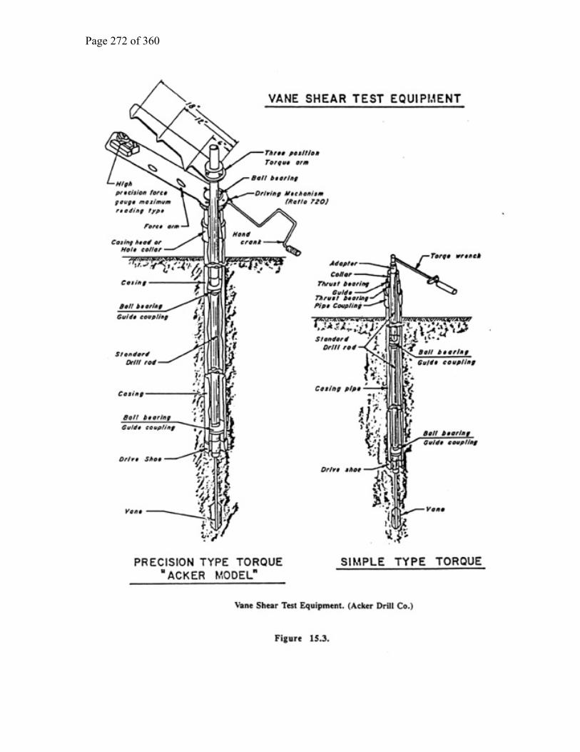
Page 272 of 360

Page 273 of 360

Page 274 of 360
Advantages of the Borehole Shear Test:
• The test is relatively quick; shear strength parameters can be determined in less than an hour in some soils.
• Erroneous shear values are usually apparent and tests may be re-run as necessary.
• Tests may be located in specific strata as they are usually performed in
completed; logged boreholes. Some of the disadvantages of the BST are uncertainty about drainage conditions in the zones being sheared, and the unsuitability of some soils to stage testing. Interference by the ends of the shear heads on soil not under normal stress may add to the apparent shear force resistance. The main components of the Borehole Shear Device are: the shear head, the pulling device, and the console. Refer to Figure 15.5 for schematics of the major components. In the shear head, curved, ridged shear plates are forced against the sides of the borehole by gas pressure (usually nitrogen) in the pistons; the pressure is controlled at the console. The knife edges at the top and bottom of the shear heads minimize end resistance. The shear head is connected to the pulling device by steel rods. The hand operated pulling device rests on a plate at ground surface, centered above the borehole. A worm gear and screw device is used for pulling the shear head, via the rods. Shear force is measured by pressure in two hydraulic cylinders. The console component includes bottled gas used to press the shear heads into the borehole sides, a pressure regulator, and pressure gauge. Pressurized gas is delivered to the shear head by plastic tubing. A general description of the performance of the Borehole Shear Test follows. To conduct a BST, a cased borehole is advanced to the depth of the test. Final hole preparation is made by advancing a 3-in thin-walled tube sampler into the borehole bottom. The test is performed in the hole thus created. The shear head is lowered down the borehole by the rods. At the proper location, the plates are expanded against the borehole sides under a controlled pressure. A ten minute wait is usually allowed for consolidation of the soil beneath the shear plates at the initial pressure. After consolidation, the pulling device is used to pull the shear head up at a constant rate of 0.002 in per second. Pulling is continued until maximum shear force is reached. Normal and shear stresses can be calculated knowing the area of the shear plates. 15.11.4.4. In Situ Testing Procedures

Page 275 of 360
A selected summary of field testing procedures required to determine various soil and rock properties follows. This summary is not intended to be all-inclusive of the many field tests currently in existence. It is intended to discuss only those basic tests and procedures which are in common use. The various field procedures are included only for general guideline purposes, realizing that specific operational details are dependent upon local practice, available equipment, and subsurface conditions. Standard and acceptable procedures in one part of the country may be prohibited or not available in other areas. 15.11.4.5. STANDARD PENETRATION TEST (SPT) (ASTM Designation D-1586, AASHTO Designation T-206) The sampler spoon consists of a 2 in O.D. by 1-3/8 in I.D., 18 in minimum length, heat treated, case-hardened, steel head, splitspoon and shoe assembly. Splitspoon or split-tube samplers are the most generally accepted method for obtaining representative, disturbed samples of the selected stratum.

Page 276 of 360

Page 277 of 360
The head is vented to prevent pressure buildup during sampling and must be kept clean. A steel ban watercheck is located in the head to prevent downward water pressure from acting on the sample. Removal of the watercheck frequently causes sample loss. The drive rods which connect the split-spoon to the drive head should have a stiffness equal to or greater than that of the A-rod. In order to maintain only minimal rod deflection, on exceptionally deep holes it may be preferable to employ N-rods. The size of the drive rods must be kept constant throughout a specific exploration program, as the energy absorbed win vary with the size and weight of the rod employed. The drop hammer used in determining SPT resistance must weigh 140 lbs. The hammer is raised with a rope activated by the drill rig cathead; no more than two turns of the rope should be allowed on the cathead. A 30 in hammer is mandatory for proper SPT determination. Extreme care must be exercised to produce consistent results. Automatic trip hammers are commercially available which insure the 30 in. freefall drop. Attach the splitspoon to the drill rods and lower the assembly to the bottom of the hole. Measure the drill rod stickup to determine if "heave" or "blow-up" of the stratum has occurred. Note any penetration of the sampler into the stratum under the weight of the rods. The 140 lb hammer is raised 30 in above the drivehead anvil and then allowed to free fall and strike the anvil. This procedure is repeated until the sampler has penetrated 18 in into the stratum at the bottom of the hole. The number of blows of the hammer required for each 6 in penetration is counted and recorded. A penetration rate of 100 blows per foot is normally considered "refusal"; however, this criterion may be varied depending upon the desired information. The penetration resistance (N) is determined by adding the second and third 6 in resistance blow counts together. Remove the sampler from the bottom of the borehole slowly to minimize disturbance. Keep the casing full of water during the removal operation. Careful measurement of drilling tools, samplers and casing must be exercised during an phases of the test boring operations, to insure maximum quality and recovery of the sample. The split-spoon is opened and carefully examined, noting all soil characteristics, color seams, disturbance, etc. A representative sample is selected and preserved in a screwtop, glass jar and properly labeled. In the event that more than one soil type is encountered in the sample split-spoon, each soil type should be preserved in a separate jar. 15.11.4.6. DYNAMIC PENETROMETER TESTS 15.11 4.6.1. Recoverable Type

Page 278 of 360
The equipment consists of a penetrometer cone (solid, conical point), drill rods to advance the boring, an anvil, and a hammer having a regulated fall. It is to be noted that dimensions and weights vary among the state organizations. The most common hammer used is the standard 140 lb with 30 in drop, and the most common cone diameter is 2 in. Another combination used is the 170 lb hammer with a 24 in regulated drop on a 3 in diameter cone. Procedure The bottom of the boring is cleaned out, and the cone threaded to the end of the drill rod is lowered to the bottom of the hole. Then the anvil is attached to the top of the drill rod with the hammer placed in position on top of the anvil. The penetrometer cone is seated at the bottom of the hole by driving it a sufficient distance to penetrate any disturbed material. The depth to the tip of the cone is recorded and reference marks are Merle on the drill rod at 6 in increments. The actual test consists of driving the cone with the chosen hammer dropped its regulated distance. As in the SPT, this regulation should preferably be accomplished mechanically by an automatic tripping mechanism, and the height of fall should be checked during driving. In relatively soft materials, the number of blows required to drive the cone at 6 in increments for a total of one foot should be recorded. 15.11.4.6.2. Expendable Type The equipment consists of an expendable penetrometer point, standard drill rod to advance the test, an anvil and a regulated drop hammer. The penetrometer point must be larger than the drill rod in order to prevent skin friction on the drill rod. The most common size penetrometer point is 2.3 in. in diameter used with 1.6 in diameter drill rod (Standard A-rod). The hammers used in this test are usually heavier than the one used in the SPT. Two in use are the 300 lb with the 30 in drop and the 350 lb with the 18 in drop. Procedure The expendable penetrometer point is attached to the drill rod through a sleeve arrangement, and the anvil and hammer are placed in position on top of the drill rod. Reference marks are then made at every foot or as needed. The actual test consists of continuously driving the penetrometer point with the regulated drop hammer. In relatively soft materials, the number of blows required per foot of

Page 279 of 360
penetration should be recorded. In hard materials, including rock, the number of blows should be recorded for each inch of penetration. Another version of the driven probe test involves the use of the "California Penetrometer." This is a cone penetrometer consisting of a 1.6 in diameter rod with a 2.3 in diameter expendable cone tip. This penetrometer is driven by a compressed air powered sheet pile hammer. The rate of penetration is recorded in seconds per foot until refusal is attained or until the driving rate equals 180 seconds per foot for the cone. 15.11.4.7. STATIC CONE PENETROMETER TESTS ASTM Test Designation D3441-86 provides standards and procedures for completing the Cone Penetrometer Test (CPT). 15.11.4.7.1. Mechanical Cone Set the thrust machine to the required test speed, generally between 2 to 4 ft/min. Prior to inserting the penetrometer into the ground, check that the assembled penetrometer tip and first push rod section are in straight alignment, the point and friction sleeve moves freely with respect to each other, and the inner rod moves freely within the push rod. If testing in cohesive materials, it is advisable to use a friction reducer section, located directly above the penetrometer. This special rod has a diameter larger than the push rods and minimizes frictional resistance on the push rods when advancing to test depths. Locate the thrust machine over the sounding location. If required, advance a borehole to the first test depth using conventional test boring techniques. Attach the penetrometer to the length of push rods required for the first test depth. Lower the penetrometer assembly into the borehole. Tests are typically completed at 8 in intervals, but the interval between tests may be decreased to 4 in to obtain more detailed information. Prior to each test increment, verify that the inner rod extends approximately 2 in above the top of the push rod. This condition indicates the penetrometer is fully collapsed and prepared for test. Move the control level on the thrust machine to the test position and advance the inner rod at the preset test speed, such that the penetrometer tip is fully extended. Record the gauge reading, indicating the cone resistance.

Page 280 of 360
If the cone has a friction sleeve, continue to advance the inner rods to engage the sleeve. Record the second gauge reading, indicating the combined resistance on the point and friction sleeve. Move the control lever on the thrust machine to collapse the penetrometer tip and advance to the next test depth. Add additional rods as required. At the completion of the tests, remove the loading head assembly and attach the rod pulling device to the thrust machine and remove penetrometer/rod assembly from the ground. Complete the cone penetration report. 15.11.4.7 2. Electrical Cone Set the thrust machine to the required speed, generally between 2 to 4 ft/min. Attach the penetrometer tip to the push rod sections (without inner rods). String the electric cable from the tip through the push rods and connect to the surface data recording system. (Note: It is preferred to pre-string the cable through all push rods required for testing, so that at the completion of each 3.3 ft thrust, the data recording system does not have to be tampered with.) If testing in cohesive soils, use a friction reducer section to minimize total friction resistance on push rods. Locate the cone penetrometer thrust rig over the sounding location. If required, advance a borehole to the first test depth using conventional test boring techniques. Lower the penetrometer/rod assembly into the borehole. Advance the penetrometer tip at the preset test speed a distance of approximately 3.3 ft.. Simultaneously, record the continuous output of cone bearing and local sleeve friction. Add additional push rods and repeat. At the completion of the tests, remove the penetrometer/rod assembly from the ground, using the rod pulling device. Complete the cone penetration report. 15.11.4.8. PRESSURE METER TEST (MENARD TYPE) The pressuremeter test consists of an expansion of a cylindrical cavity formed in the ground in order to measure the relationship between pressure and deformation for the

Page 281 of 360
soil. The pressuremeter test is extremely sensitive to borehole disturbance and all drilling procedures should minimize disturbance of the soil strata to be tested. It is recommended that experienced personnel supervise all pressuremeter field work. 15.11.4.8.1. Procedure Borehole Advancement: The following procedures may be used as necessary to maintain borehole stability and minimize borewall disturbance: a) Wash boring techniques using flush-joint, steel casing may be driven to within 2 ft of the zone to be tested. Uncased wash boring techniques require a weighted drilling mud to maintain borewall stability. b) Machine operated, continuous flight augers may be used in preparing the test borehole. The rate of auger advance and withdrawal must be very slow in order to minimize borewall disturbance. c) Large diameter, thin-wall tube samplers are generally used to prepare the test area below the bottom of the casing. Tube samplers should be pressed, whenever possible and not driven into the undisturbed test zone. The tube sampler should not be twisted during removal. d) Rotary core drilling techniques, utilizing drilling mud, are generally used for advancing the borehole into weathered or sound rock. e) Extreme care must be exercised at all time for any borehole advancement method in order to minimize borehole disturbance in the desired test zone. l5. l1.4.8.2. Equipment The pressuremeter consists of three parts: the probe, the control unit, and the tubing: a) The probe Water is used to pressurize the cavity and to measure the resulting volume change. It is contained in a flexible, impervious rubber bladder which fills the cavity and defines its length. To make sure that the cavity expands as it should, the measuring cell is flanked top and bottom by guard cells which are also rubber bladders and which are inflated by gas to the same pressure as the measuring cell. The inflated guard cells effectively seal off the borehole and prevent the measuring cell membrane from expanding into the void of the hole. b) The control unit

Page 282 of 360
The control unit is located at a convenient spot on the ground surface close to the hole, and its function is to control and monitor the expansion of the probe. It does this by applying a given pressure on command to the probe and then measuring the volume change of the measuring cell. The pressure source is a bottle of compressed gas; the flow of water to the measuring cell is monitored using a graduated cylinder which is called the volumeter. c) The tubing Tubing is required between the control unit and the probe to allow water and gas to be sent from one to the other. 15.11.4.8.3. Testing The test is simply a process of simultaneously applying gas and water pressure at the volumeter through the tubing to the probe. When a desired pressure is reached, it is held constant for one minute and volume readings observed in the sight tube are recorded fifteen, thirty and sixty seconds after the pressure level is attained. Another increment of pressure is added at a steady rate of 21 p.s.i. per minute, and held constant at the next desired level, and fifteen, thirty and sixty second volume readings are again recorded at this new pressure. Between eight and fourteen pressure increments are used before advancing the test hole to the next deeper test level. Unloading and reloading sequences may be performed, however, unloading should not be done until at least four points on the linear (elastic) portion of the volume vs. pressure plot have been attained. 15.11.4.9. BOREHOLE SHEAR TEST (Iowa Type) The borehole shear test employs a pair of corrugated plates attached to an expandable shear head. The plates are activated by gas pressure and pressed against the walls of a borehole. A constant pressure is applied and the shear plates are pulled upward. 15.1 l.4.9.1. Procedure Prepare a smooth, flat and firm working area around the borehole which will accommodate the pulling device. Advance a borehole to a point just above the required test depth by drilling or augering. Advance the borehole to the required test location by either careful hand angering, or pressing a 3 in thin-walled tube sampler or driving a 3 in.-OD. splitspoon sampler. The test will be performed in the resulting hole. Location of test must be at least l ft below the bottom of the borehole casing, if casing is used.

Page 283 of 360
Lower the shear head to the desired test depth, with the necessary length of pulling rods attached. Place the base plate and attached mechanism over the rods extending from the borehole and set the base plate on firm leveled ground. The pulling unit must be perpendicular to the axis of the borehole. Complete assembly of the pulling unit. Make final adjustment of depth of shear head. Check for free movement of the pulling device. Clamp pulling rods in pulling device. Connect the compressed gas lines from the shear head to the console. Begin the test by applying the first desired normal pressure to the shear head using the regulator valve on the console. Allow at least 10 minutes for initial consolidation of soil. After the consolidation period, perform the shear test as follows: a) Turn the crank on the pulling device to pull the shear head upwards at a rate of 0.002 in per second. b) At intervals of 30 seconds, record the pressure shown on the hydraulic gauge on the pulling device. c) Continue pulling the shear head at a constant rate until either an observable shear occurs, as evidenced by a drop in hydraulic gauge readings, or the pressure remains constant for at least 5 minutes. d) After the maximum shear force has been attained, unload the pulling rods by turning the crank in the opposite direction until the hydraulic gauge indicates 1 p.s.i. or less. Increase the shear head normal pressure to the next desired level and allow the soil to consolidate for at least 5 minutes. Generally at least 5 normal pressure levels are performed per location to allow ready interpretation of the plotted area. After completion of all tests at a given depth, turn the crank so as to reduce the pressure indicated on the hydraulic gauge to less than 1 p.s.i. Relieve the normal pressure on the shear head and remove the pulling device and shear head. Advance the borehole to the depth at which the next test is required. 15.11.4.10. WATER PRESSURE TEST

Page 284 of 360
Water pressure tests are performed in situ, within test borings, to measure the permeability of a soil or rock mass. Pressure testing helps to locate zones of leakage, measuring the capacity of such zones for transmitting water, and useful in estimating grouting and dewatering requirements for construction purposes. 15.11.4.10.1. Equipment 1. Pump, water (non-centrifugal preferred) 2. Meter, water (measures flow to 0.1 gallon) 3. Gauge, pressure (PSI; calibrated) 4. Packer system (pneumatic or mechanical) 5. Tank, surge (optional, depending on pump type) 6. Drill rig 7. Miscellaneous pipe and fittings 8. Valve, bypass (for regulating water pressures) 9. Hose, air, reinforced 10. Tank, nitrogen or oxygen, with pressure regulator and two gauges 11. Time piece 12. Ruler 13. Forms Determine Maximum Allowable Gauge Pressure (MGP) according to the formula below. In order to avoid hydrofracturing (loosening) the rock mass, do not exceed MGP during testing. MGP = Maximum Gauge Pressure = ZK Z = Depth (feet) from top of upper packer to ground surface K = 0.75 (constant) Lower test apparatus to specified test depth, inflate both packers to at least 150 p.s.i. Double packers are usually spaced at 5 ft., but spacing can be varied to meet specific test requirements. Before starting test, record the following: a) Test number b) Test section c) Hole size d) Height of pressure gauge above ground surface e) Ground surface elevation f ) Depths to rock surface, groundwater, bottom of boring, bottom of upper packer and top of lower packer. Pump water into the system Attain and hold pressure at 1/3 and 2/3 of the MGP for 3 minutes, taking flow readings every thirty seconds. Attain and hold MGP for 10 minutes taking flow readings every minute. If leakage of water, from the packed section, into the surrounding rock is so great that the MGP cannot be reached, run the pump at its full capacity with the by-pass valve closed;

Page 285 of 360
record the amount of water pumped into the test section, at 30 second intervals, with associated pressure readings. Conclusions These procedures describe the necessary fundamental operations that must be followed to successfully complete test programs using the tools described. Variations on the procedures may be used as field conditions dictate.
Chapter 16
DRILLING SAFETY GUIDE
1. An Introduction to Drilling Safety
The organization for which you work is interested in your safety. Your employer cares about your safety not only when you are working on or around a drill rig, but also when you are traveling to and from a drilling site, moving the drill rig and tools from location to location on a site, or providing maintenance on a drill rig or drilling tools. This safety guide is for your benefit. Failure to heed the safety procedures contained in this manual could result in serious injury or death.
Every drill crew should have a designated safety supervisor who has the authority to enforce safety on the drilling site. A rig worker's first safety responsibility is to obey the directions of the safety supervisor. 2. Governmental Regulations

Page 286 of 360
All local, state, and federal regulations or restrictions, currently in effect or effected in the future, take precedence over the recommendations and suggestions which follow. Government regulations will vary from country to country and from state to state. Those who operate, maintain, and work on drill rigs must be trained in the operation and maintenance of the drill. They must have read and understood the manufacturer’s instruction manual, and know the ratings and capabilities of the drill they are using. They must be licensed if required by law. 3. The Safety Supervisor
The safety supervisor for the drill crew will, in most cases, be the drill rig operator. The safety supervisor must:
• Consider the "responsibility" for safety and the "authority" to enforce safety to be a matter of first importance.
• Be the leader in using proper personal safety gear and set an example in following the rules that are being enforced on others.
• Enforce the use of proper personal protective safety equipment and take appropriate corrective action when proper personal protective safety equipment is not being used.
• Understand that proper maintenance of tools and equipment and general "housekeeping" on the drill rig will provide an environment that will promote and enhance safety.
• Before drilling is started with a particular drill, ensure that anyone who operates the drill has had adequate training and is thoroughly familiar with the drill rig, its controls, and its capabilities.
• Inspect the drill rig at least daily for structural damage, loose bolts and nuts, proper tension in chain drives, loose or missing guards or protective covers, fluid leaks, damaged hoses, and/or damaged pressure gauges and pressure relief valves.
• Check and test all safety devices, such as emergency shutdown switches, at least daily and preferably at the start of a drilling shift. Drilling must not be permitted until all emergency shutdown and warning systems are working correctly. Do not allow any emergency device to be bypassed or removed.
• Check that all gauges, warning lights, and control levers are functioning properly and listen for unusual sounds each time an engine is started.
• Ensure that every drill rig worker is informed of safe operating practices on and around the drill rig. Provide every drill rig worker with a copy of the organization's drilling operations safety manual, and when appropriate, the drill rig manufacturer's operations and maintenance manual. Ensure that every employee reads and understands the safety manual.

Page 287 of 360
• Carefully instruct a new worker in drilling safety and observe the new worker's progress towards understanding safe operating practices.
• Assess the mental, emotional, and physical capability of each worker to perform the assigned work in a proper and safe manner. Remove any worker from the drill site whose mental and physical capabilities might cause injury to the worker or coworkers.
• Ensure that a first aid kit and a fire extinguisher, which are properly maintained, are on each drill rig and each additional vehicle.
• Be well trained in and capable of using first aid kits, fire extinguishers, and all other safety devices and equipment. Train crew members.
• Maintain a list of addresses and telephone numbers of emergency assistance units (ambulance services, police, hospitals, etc.) and inform other members of the drill crew of the existence and location of the list.
• In order to mitigate emergency situations, it may be appropriate to coordinate communication methods (cellular telephone, two-way ratio, etc.) at remote sites.
4. Individual Protective Equipment
For most geotechnical, mineral, and/or groundwater drilling projects, individual protective equipment must include a safety hat, safety shoes, safety glasses, and close fitting gloves and clothing. The clothing of the individual drill rig worker is not generally considered protective equipment; however, the worker's clothing should be comfortable but must be close fitting, without loose ends, straps, draw strings, belts or otherwise unfastened parts that might catch on some rotating or translating component of the drill rig. Rings and jewelry must not be worn during a work shift. In addition to loose clothing, hair should be tied back; as loose/long hair can catch in mechanical equipment.

Page 288 of 360
• Safety Head Gear. Safety hats (hard hats) must be worn by everyone working or visiting at or near a drilling site. All safety hats must meet the requirements of ANSI Z89.1. AII safety hats must be kept clean and in good repair with the headband and crown straps properly adjusted for the individual drill rig worker or visitor.
• Safety Shoes or Boots. Safety shoes or boots must be worn by all drilling personnel and all visitors to the drill site that observe drilling operations within close proximity of the drill rig. All safety shoes or boots must meet the requirements of ANSl Z41.1.
• Gloves. All drilling personnel must wear gloves for protection against cuts and abrasions that could occur while handling wire rope or cable and from contact with sharp edges and burrs on drill rods and other drilling or sampling tools. All gloves must be close fitting and not have large cuffs or loose ties that can catch on rotating or translating components of the drill rig.
• Safety Glasses. All drilling personnel must wear safety glasses. General prescription glasses and/or sunglasses are not safety glasses. All safety glasses must meet the requirements of ANSl Z87.1 - 1989.
• Other Protective Equipment. For some drilling operations, the environment or regulations may dictate that other protective equipment be used. The requirement for such equipment must be determined jointly by the management of the drilling organization and the safety supervisor. Such equipment might include face shield, respirator, reflective clothing and hearing protection. When appropriate, each drill rig worker must wear noise-reducing hearing protection that meets the requirements of ANSI S3.19 – 1974.
When drilling is performed in chemically or radiologically contaminated environment, special protective equipment and clothing may, and probably will, be required. The design and composition of the protective equipment and clothing must be determined jointly by the management and the client who requests the drilling services, and under some circumstances, with the concurrence of a health and safety professional.
5. Housekeeping On and Around the Drill Rig
The first requirement for safe field operations is that the safety supervisor understand and fulfill the responsibility for maintenance and “housekeeping" on and around the drill rig. The safety supervisor must:
• Provide suitable storage locations for all tools, materials, and supplies so that these items can be conveniently and safely handled without hitting or falling on a member of the drill crew or a visitor.
• Avoid storing or transporting tools, materials, or supplies within or on the mast (derrick) of the drill rig, unless designed for this purpose.

Page 289 of 360
• Stack pipe, drill rods, casing, augers, and similar drilling tools in orderly fashion on racks or sills to prevent spreading, rolling, or sliding.
• Place penetration or other driving hammers at a safe location on the ground or secure them to prevent movement when not in use.
• Keep work areas, platforms, walkways, scaffolding, and other accessways free of materials, debris, obstructions, and substances such as ice, grease or oil that could cause a surface to become slick or otherwise hazardous.
• Keep all controls, control linkages, warning and operation lights and lenses free of oil, grease, and/or ice.
• Store gasoline only in a non sparking, red container with a flame arrester in the fill spout and having the word "gasoline" easily visible.
• All fluid/material containers should be clearly labeled to avoid improper use. Hazardous materials should be labeled and handled accordingly. Refer to MSDS sheets.
• Keep all cabs clean. Mud, cans, bottles, tools, and other debris can jam pedals and other controls and can cause falls.
6. Maintenance
Good maintenance will make drilling operations safer. Also, maintenance must be performed safely. The following points are essential to safety:
• Wear safety glasses when performing maintenance on a drill rig or on drilling tools.
• Shut down the drill rig engine to make repairs or adjustments to a drill rig or to lubricate fittings (except repairs or adjustments that can only be made with the engine running). Take precautions to prevent accidental starting of an engine during maintenance by removing or tagging the ignition key. Refer to lock-out/tag-out rules spelled out by OSHA.
• Block the wheels or tracks and set parking brakes before working under a drill rig. • Release all pressure on the hydraulic systems, the drilling fluid system and the air
pressure systems of the drill rig—when possible and appropriate—prior to performing maintenance. In other words, reduce the drill rig and operating systems to a "zero energy state" before performing maintenance. Use extreme caution when opening drain plugs and radiator caps and other pressurized plugs and caps.
• Do not touch an engine or the exhaust system of an engine following its operation until the engine and exhaust system have had adequate time to cool.
• Never climb the mast (derrick) to do maintenance or make repairs. Lower mast, stop engine and deenergize rig before starting maintenance or repair on mast.
• Never weld or cut on or near a fuel tank.

Page 290 of 360
• Do not use gasoline or other volatile or flammable liquids as a cleaning agent on or around a drill rig.
• Follow the manufacturer's recommendations for applying the proper quantity and quality of lubricants, hydraulic oils and/or coolants.
• Replace all caps, filler plugs, protective guards or panels, and high pressure hose clamps and chains or cables that have been removed for maintenance before returning the drill rig to service.
• Watch for broken hydraulic or air hoses. Replace them before they cause damage or a fire.
• Tighten or replace loose or broken fittings, bolts, or other connections before operating the drill.
• Do not replace a hose with one of lesser strength or capacity. Breakage or leakage could result.
• Never remove cooler fan guards unless the drill is shut down and locked out. • When testing fan speed, do so with the guard in place. • Relieve all pressure in receiver tank and lines before working on compressor
system.
7. Hand Tools
Since there are almost an infinite number of hand tools that can be used on or around a drill rig and in repair shops, there are an equal number of instructions for proper use. "Use the tool for its intended purpose" is the most important rule. The following suggestions apply to safe use of several hand tools that frequently are used on and around drill rigs:
• When a tool becomes damaged, either repair it before using it again or get rid of it.
• When using a hammer, any kind of hammer for any purpose, wear safety glasses and require all others around you to wear safety glasses.
• When using any kind of chisel or punch, for any purpose, wear safety glasses and require all others around you to wear safety glasses.
• Keep all tools cleaned and stored appropriately when not in use.
• Use wrenches—not pliers—on nuts. • Use screwdrivers with blades that fit the screw. • Keep all pipe wrenches clean and in good
repair. Use a wire brush frequently to clean the jaws of pipe wrenches. An accumulation of dirt and grease can cause wrenches to slip.
• Never use pipe wrenches in place of a rod holding device.
• Replace hook and heel jaws when they become visibly worn.

Page 291 of 360
• When breaking tool joints on the ground or on a drilling platform, position your hands so that your fingers will not be pinched between the wrench handle and the ground or the platform if the wrench should slip or the tool joint suddenly let go.
8. Clearing the Work Area
Prior to drilling, adequately clear and level the site to accommodate the drill rig and supplies and provide a safe working area. Do not begin drilling if tree limbs, unstable ground, or site obstructions cause unsafe tool handling conditions. 9. Start Up
• Instruct all drill rig personnel and visitors to "stand clear" of the drill rig immediately prior to starting the engine.
• Make sure all brakes are set, all gear boxes are in neutral, all hoist levers are disengaged, all hydraulic levers or air controls are in the correct positions, and the cathead rope is not on the cathead before starting a drill rig engine.
• Start all engines according to the manufacturer's manual. • Check for warning or lockout tags on the controls. If there is a tag attached to the
switch, do not start the engine until the warning tag has been removed by the person who installed it.
10. Drilling Operations
Safety requires the attention and cooperation of every worker and site visitor.
• Do not drive the drill rig from hole to hole with the mast (derrick) in the raised position.
• Before raising the mast (derrick), look up to check for overhead obstructions. (Refer to Section 11 on Overhead and Buried Utilities.)
• Before raising the mast (derrick), clear all drill rig personnel (with exception of the operator) and visitors from the areas immediately to the rear and the sides of the mast. Inform all drill rig personnel and visitors that the mast is being raised prior to raising it.
• Before the mast (derrick) of a drill rig is raised and drilling is begun, the drill rig must first be leveled and stabilized with leveling jacks and/or solid cribbing. Relevel the drill rig if it settles after initial set up. Lower the mast (derrick) only when the leveling jacks are down and do not raise the leveling jack pads until the mast (derrick) is lowered completely.
• Before starting drilling operations, secure, and/or lock the mast (derrick) if required, according to the drill manufacturer's recommendations.
• Do not stand on the elevated deck of a truck mounted or all-terrain mounted drill rig while the drill rig is in operation unless necessary for special tasks and the operator has been notified.
• Only operate a drill rig from the position of the controls. Before leaving the area of the controls, shift the transmission controlling the rotary drive into neutral and
Page 292 of 360
place the feed lever in neutral. Before leaving the vicinity of the drill, shut down the drill engine.
• Throwing or dropping tools must not be permitted. Carefully pass tools by hand between personnel or use a hoist line.
• Do not consume alcoholic beverages, other depressants, or chemical stimulants prior to starting work on a drill rig or while on the job.
• If it is necessary to drill within an enclosed area, make certain that exhaust fumes are conducted out of the area. Exhaust fumes are toxic and some cannot be detected by smell.
• Clean mud and grease from boots before stepping on a drill platform and use hand holds and railings. Watch for slippery ground when stepping down from the platform.
• During freezing weather, do not touch any metal parts of the drill rig with exposed flesh. Freezing of moist skin to metal can occur almost instantaneously.
• Drain all air and water lines and pumps when not in use if freezing weather is expected.
• Adequately cover or protect all unattended boreholes to prevent drill rig personnel, site visitors, or animals from stepping or falling into the hole. Cover, protect or backfill all open boreholes according to local or state regulations on completion of the drilling project.
• Never allow "horsing around" within the vicinity of the drill rig and tool and supply storage areas, even when the drill rig is shut down.
• When using a ladder on a drill rig, face the ladder and grasp either the side rails or the rungs with both hands while ascending or descending. Do not attempt to use one or both hands to carry a tool while on a ladder. Use a hoist line and a tool "bucket" or a safety hook to raise or lower hand tools.
• Terminate drilling operations during an electrical storm and move the complete crew away from the drill rig.
• Check all safety devices. Report any defect immediately. • Never drill without having another person present. • Before raising the mast (derrick), make sure it is clear of all objects that could
fall. Check that all hydraulic and air hoses do not become snagged during raising. Watch all hoist cables and keep them clear or unspooled properly while raising derricks.
• Use the proper tools for the job. Do not attempt to lift pipes, subs, stabilizers or bits without the proper lifting devices.
• Use the proper technique in loading and unloading the drill pipe. If a lifting bail is used, make sure it can be detached while standing on the ground. Use a pipe handling tool if the carousel needs to be filled. Make sure the safety clip is in place (if so equipped).
• Never ride the rotary head for any reason!!! It is not meant to be an elevator. • If heavy objects must be manually lifted, exercise care to avoid injury. • Before lifting an object without using a hoist, make sure that the load is within
your personal lifting capacity. If it is too heavy, ask for assistance. • Before lifting a relatively heavy object, approach the object by bending at the
knees, keeping the back vertical and unarched while obtaining a firm footing.

Page 293 of 360
Grasp the object firmly with both hands and stand slowly and squarely while keeping the back vertical and unarched. In other words, perform the lifting with the muscles in the legs, not with the muscles in the lower back.
• If a heavy object must be moved some distance without the aid of machinery, keep the back straight and unarched. Change directions by moving the feet, not by twisting the body.
• Move heavy objects with the aid of hand carts whenever possible. • An elevated derrick platform should be used with the following precautions: • When working on a derrick platform, use a safety harness and refer to OSHA
REG CFR 1926.502 for specific requirements. • Use a safety device when climbing to a derrick platform that is higher than 6 ft.
(1.8 m) refer to OSHA REG CFR 1926.501 for specific requirements. • When on a derrick platform, fasten the lifeline to the derrick just above the
derrick platform and to a structural member that is not attached to the platform or to other lines or cables supporting the platform.
• When first arriving at a derrick platform, immediately inspect for broken members, loose connections, loose tools, or other loose materials.
• Securely attach tools to the platform with safety lines. Do not attach a tool to a line attached to one's wrist or any other part of the body.
• When working on a derrick platform, do not guide drill rods or pipe into racks or other supports by taking hold of a moving hoist line or a traveling block.
• Do not leave loose tools and similar items on the derrick platform or on structural members of the derrick.
• A derrick platform or operators platform over 4 ft. (1.2 m) above ground surface must have toe boards and safety railing that are in good condition, refer to OSHA REG CFR 1910.23 for specific requirements.
• Avoid being under rig workers on elevated platforms whenever possible.
11. Overhead and Buried Utilities
Both supervisors and members of the exploration crew must take special precautions when a drill rig will be used on a site or project within the vicinity of electrical power lines and other utilities. Electricity can shock, it can burn, and it can cause death.
• Locate, note, and emphasize overhead and buried utilities on all boring location plans and boring assignment sheets.
• When overhead electrical power lines exist at or near a drilling site or project, consider all wires to be alive and dangerous.
• Watch for sagging power lines before entering a site. Do not lift power lines to gain entrance. Call the utility and ask them to lift or raise the lines or deenergize (turn off) the power.

Page 294 of 360
• Before raising the drill rig mast (derrick) on a site in the vicinity of power lines, walk completely around the drill rig. Determine the minimum horizontal distance from any point on the drill rig to the nearest power line when the mast is raised and/or being raised. If this horizontal distance is less than 100 ft. (30 m), first consult the local utility company and refer to OSHA REG 29 CFR 1910.333 before commencing operations.
• Keep in mind that both hoist lines and overhead power lines can be moved toward each other by the wind.
• In order to avoid contact with power lines, only move the drill rig with the mast (derrick) down.
• If there are any questions concerning the safety of drilling on sites in the vicinity of overhead power lines, call the power company. The power company will provide expert advice at the drilling site as a public service and at no cost.
• Electricity is as dangerous underground as overhead. Be aware of and always suspect the existence of underground utilities such as electrical power, gas, petroleum, telephone, sewer and water.
• If a sign warning of underground utilities is located on a site boundary, do not assume that underground utilities are located on or near the boundary or property line under the sign. Call the utility and check it out. The underground utilities may be a considerable distance away from the warning sign.
• Always contact the owners of utility lines or the nearest underground utility location service before drilling. Determine jointly with utility personnel the precise location of underground utility lines, mark and flag the locations, and determine jointly with utility personnel what specific precautions must be taken to ensure safety.

Page 295 of 360
12. Supplying Power to the Job Site
Drilling projects sometimes require around the clock operations and, therefore, require temporary electrical lighting. In general, all wiring and fixtures used to provide electricity for drilling operations should be installed by qualified personnel in accordance with the National Electrical Code (NFPA70 1999) with consideration of the American Petroleum Institute's recommended practices for electrical installations for production facilities (API RP 500B). Lights should be installed and positioned so that the work area and operating positions are well lighted without shadows or blind spots. The following are specific recommendations for land based drilling operations:
• Before working on an electrical power or lighting system, lockout the main panel box with your own lock and keep the key on your person at all times.
• Install all wiring using high quality connections, fixtures and wire. Be sure that the wiring is insulated and protected with consideration for the drilling environment. Do not use makeshift wiring and equipment.
• Place all lights positioned directly above working areas in cages or similar enclosures to prevent loose or detached lamps or vaportight enclosures from falling on workers.
• Install lights so as to eliminate glare or "blind spots" on tools, ladders, walkways, platforms, and the complete working area.
• Locate and guard electrical cables to prevent damage by drilling operations or by the movement of personnel, tools, or supplies.
• Use only three prong, U blade, grounded type plug receptacles and have adequate current carrying capacity for the electrical tools that may be used.
• Use only electrical tools that have three prong, U blade, ground wire plugs and cords.
• Do not use electrical tools with lock on devices. • Provide adequate grounding for all electrical welders, generators, control panels,
and similar devices. • Provide secure protective enclosures on control panels, fuse boxes, transformers,
and similar equipment. • Avoid attaching electrical lighting cables to the derrick or other components of
the drill rig. If this must be done, use only approved fasteners. Do not "string" wire through the derrick.
• Do not use poles used to hold wiring and lights for any other purpose.

Page 296 of 360
• Turn power off before changing fuses or light bulbs. • Require all workers in a drilling area illuminated with electrical lighting to wear
safety head gear that protects the worker's head, not only against falling or flying objects, but also against limited electrical shock and burns according to ANSI Z89.1 and Z89.2.
• Allow only trained, designated personnel to operate electrical equipment. • Do not permit unqualified field personnel to work on or near electric lines or
devices.
13. Contact with Electricity
If a drill rig makes contact with electrical wires, it may or may not be insulated from the ground by the tires of the carrier. Under either circumstance, if the human body simultaneously comes in contact with the drill rig and the ground, electrocution can result, causing death or serious injury. If a drill rig or a drill rig carrier makes contact with overhead or underground electrical lines:
• Under most circumstances the operator and other personnel on the seat of the vehicle should remain seated and not leave the vehicle. They should not move or touch any part, particularly a metallic part, of the vehicle or the drill rig.
• If it is determined that the drill rig should be vacated, all personnel must jump clear and as far as possible from the drill. Personnel must not step off—but must jump off. Do not hang on to the vehicle or any part of the drill when jumping clear.
• If you are on the ground, stay away from the vehicle and the drill rig; do not allow others to get near the vehicle and the drill rig. Seek assistance immediately from local emergency personnel such as the police or a fire department.
• When an individual is injured and in contact with the drill rig or with power lines, attempt rescue with extreme caution. If a rescue is attempted, use a non-conductive material, such as a dry nylon rope. Keep as far away from the victim as possible and do not touch the victim until the victim is completely clear of the drill rig or electrical lines.
• Do not attempt to administer first aid unless the victim is completely clear of the electrical source. Begin cardiopulmonary resuscitation (CPR) immediately if a heart beat (pulse) cannot be detected.
14. Wire Line Hoists, Wire Rope, and Hoisting Hardware
Use wire line hoists, wire rope, and hoisting hardware only as stipulated by the American Iron and Steel Institute Wire Rope Users Manual.
• Visually inspect all wire ropes and fittings during use and thoroughly inspect them at least once a week for abrasion, broken wires, wear, reduction in rope diameter, reduction in wire diameter, fatigue, corrosion, damage from heat, improper reeving, jamming, crushing, bird caging, kinking, core protrusion,

Page 297 of 360
and/or damage to lifting hardware. Replace wire ropes when inspection indicates excessive damage, as described in the Wire Rope Users Manual.
• Thoroughly inspect all wire ropes that have not been used for a period of a month or more.
• Install all connections and end fittings, which consist of spliced eyes and various manufactured devices, according to the manufacturer's specifications. Do not exceed ratings specified by manufacturer.
• If a ball bearing type hoisting swivel is used to hoist drill rods, inspect and lubricate swivel bearing daily to assure that the swivel freely rotates under load.
• If a rod slipping device is used to hoist drill rods, do not drill through or rotate drill rods through the slipping device; do not hoist more than 1 ft. (0.3 m) of the drill rod column above the top of the mast (derrick); do not hoist a rod column with loose tool joints; and do not make, tighten, or loosen tool joints while the rod column is being supported by a rod slipping device. If drill rods should slip back into the borehole, do not attempt to break the fall of the rods by hand or by tensioning the slipping device.
• Most sheaves on drill rigs are stationary with a single part line. Never increase the number of parts of line without first consulting with the manufacturer of the drill rig.
• Wire ropes must be properly matched with each sheave. If the rope is too large, the sheave will pinch the wire rope. If the rope is too small, it will groove the sheave. Once the sheave is grooved, it will severely pinch and damage larger sized wire ropes.
• Always use proper lifting devices.
The following procedures and precautions must be understood and implemented for use of wire ropes and rigging hardware:
• Use tool handling hoists only for vertical lifting of tools (except when angle hole drilling). Do not use tool handling hoists to pull on objects away from the drill rig; however, drills may be moved using the main hoist of the drill if the wire rope is spooled through proper sheaves according to the manufacturer's recommendations.
• When stuck tools or similar loads cannot be raised with a hoist, disconnect the hoist line and connect the stuck tools directly to the feed mechanism of the drill. Do not use hydraulic leveling jacks for added pull to the hoist line or to the feed mechanism of the drill.
• When attempting to pull out a mired down vehicle or drill rig carrier, only use a winch on the front or rear of the vehicle and stay as far as possible away from the wire rope. Do not attempt to use tool hoists to pull out a mired down vehicle or drill rig carrier.
• Apply loads smoothly and steadily to minimize shock loading of a wire rope. • Avoid sudden loading in cold weather. • Never use frozen ropes. • Protect wire rope from sharp corners or edges. • Replace faulty guides and rollers.

Page 298 of 360
• Replace worn sheaves or worn sheave bearings. • Replace damaged latches on hooks before using. • Know the working load of the equipment and tackle being used. Never exceed
this limit. • Periodically inspect and test hoist clutches and brakes. • Know and do not exceed the rated capacity of mast hooks rings, links, swivels,
shackles, and other lifting aids. • Always wear gloves when handling wire ropes. • Do not use hands to guide wire rope on hoist drums. • Following the installation of a new wire rope, first lift a light load to allow the
wire rope to adjust. • Never conduct any hoisting operations when the weather conditions are such that
hazards to personnel, the public, or property are created. • Never leave a load suspended in the air when the hoist is unattended. • Keep hands away from hoists, wire rope, hoisting hooks, sheaves, and pinch
points while slack is being taken up or when the load is being hoisted. • Never hoist the load over the head, body, or feet of any personnel. • Never use a hoist line to "ride" up the mast (derrick) of a drill rig. • Use replacement wire ropes that conform to the drill rig manufacturer's
specifications.
15. Cathead and Rope Hoists
Follow these procedures when using a cathead hoist:
• Keep the cathead clean and free of rust, oil and grease. Rust should be removed from the cathead with a wire brush having a handle.
• Check the cathead periodically, when the engine is not running, for rope wear grooves. If a rope groove forms to a depth greater than 1/8 in. (3 mm), replace the cathead.
• Always use a clean, dry, sound rope. A wet or oily rope may "grab" the cathead and cause drill tools or other items to be rapidly hoisted to the top of the mast.
• Should the rope "grab" the cathead or otherwise become tangled in the drum, release the rope and sound an appropriate alarm for all personnel, including the operator, to rapidly back away and stay clear. If the rope "grabs" the cathead, and tools are hoisted to the sheaves at the top of the mast, the rope will often break, releasing the tools. If the rope does not break, stay clear of the drill rig until the operator cautiously returns to turn off the drill rig engine and appropriate action is taken to release the tools. Keep careful watch on the suspended tools and quickly back away after turning off the engine.
• Always protect the rope from contact with chemicals. Chemicals can cause deterioration of the rope that may not be detected visibly.
• Never wrap the rope from the cathead (or any other rope, wire rope, or cable on the drill rig) around a hand, wrist, arm, foot, ankle, legs, or any other part of the body.

Page 299 of 360
• Always maintain a minimum of 18 inches (46 cm) of clearance between the operating hand and the cathead drum when driving samplers, casing, or other tools with the cathead and rope method. Be aware that the rope advances toward the cathead with each hammer blow as the sampler or other drilling tool advances into the ground.
• Never operate a cathead (or perform any other task around a drill rig) with loose, unbuttoned, or otherwise unfastened clothing or when wearing gloves with large cuffs or loose straps or lacings.
• Do not use a rope that is any longer than necessary. A rope that is too long can form a ground loop or otherwise become entangled with the operators legs.
• Do not use more rope wraps than are required to hoist a load.
• Do not leave a cathead unattended with the rope wrapped on the drum.
• Position all other hoist lines to prevent contact with the operating cathead rope.
• When using the cathead and rope for driving or back driving, make sure that all threaded connections are tight and stay as far away as possible from the hammer impact point.
• Only operate the cathead standing on a level surface with good, firm footing conditions without distraction or disturbance.
16. Augers
Follow these general procedures when starting a boring with continuous flight or hollow stem augers:
• Start an auger boring with the drill rig level, the clutch or hydraulic rotation control disengaged, the transmission in low gear, and the engine running at low RPM.
• Apply an adequate amount of down pressure prior to rotation to seat the auger head below the ground surface.
• Look at the auger head while slowly engaging the clutch or rotation control and starting rotation. Stay clear of the auger.
• Slowly rotate the auger and auger head while continuing to apply down pressure. Keep one hand on the clutch or on the rotation control at all times until the auger has penetrated about one foot or more below ground surface.
• If the auger head slides out of alignment, disengage the clutch or hydraulic rotation control and repeat the hole starting process.
• An auger guide can facilitate the starting of a straight hole through hard ground or a pavement.
• Establish a system of responsibility for the operator and tool handler to follow during the series of various activities required for auger drilling, such as connecting and disconnecting auger sections, and inserting and removing the

Page 300 of 360
auger fork. The operator must ensure that the tool handler is well away from the auger column and that the auger fork is removed before starting rotation. In addition:
• When rotating augers, stay clear of the rotating auger and other rotating components of the drill rig. Never reach behind or around a rotating auger for any reason whatsoever.
• Only use the manufacturer's recommended method for securing the auger or drive adapter to the power coupling. Do not use an over length pin or bolt. Do not touch the coupling or the auger with hands, a wrench, or any other tools during rotation.
• Whenever possible, use tool hoists to handle auger sections. • Never place hands or fingers under the bottom of an auger section when hoisting
the auger over the top of the auger section in the ground or other hard surfaces such as the drill rig platform.
• Never allow feet to get under the auger section that is being hoisted. • Use a long-handled shovel to move auger cuttings away from the auger. Never
use hands or feet to move cuttings away from the auger. • Do not attempt to remove earth from rotating augers. Clean augers only when the
drill rig is in neutral and the augers are stopped from rotating.
17. Rotary and Core Drilling
Check rotary drilling tools prior to drilling:
• Lubricate and check for frozen bearings before using water/air swivels and hoisting plugs. Water/air swivel bearings must be free before using, and stay clear of water/air swivel hose when rotating.
• Check drill rod chuck jaws periodically and replace when necessary. • Check the capacities of hoists and sheaves against the anticipated weight to the
drill rod string plus other expected hoisting loads.
During rotary or core drilling, follow these special precautions that involve chucking, joint break, hoisting, and lowering of drill rods:
• Only the operator of the drill rig should be allowed to brake or set a manual chuck so that rotation of the chuck will not occur prior to removing the wrench from the chuck.
• Drill rods should not be braked during lowering into the hole with drill rod chuck jaws.
• Do not lower drill rods into the hole with pipe wrenches. • If a string of drill rods is accidentally or inadvertently released into the hole, do
not attempt to grab the falling rods by hand or with a wrench. • In the event of a plugged bit or other circulation blockage, relieve the high
pressure in the piping and hose between the pump and the obstruction before breaking the first tool joint.

Page 301 of 360
• When drill rods are hoisted from the hole, clean them only with a wiper made of rubber or other suitable material. Do not use hands to clean drilling fluid from drill rods.
• If work must progress above a portable drilling fluid (mud) pit, do not attempt to stand on narrow sides or cross members. Equip the mud pit with rough surfaced, fitted cover panels of adequate strength to hold drill rig personnel.
• Do not lift or lean unsecured drill rods against the mast. Either provide some method of securing the upper ends of the drill rod sections for safe vertical storage or lay the rods down.
18. Air Drilling
Compressed air is dangerous and explosive in nature. High pressure air can cause serious injuries.
• Do not allow tools or air powered equipment to be connected to the drill hoses. They must be attached to the service regulator and the pressure adjusted to the working capacity of the tool being used.
• Turn off drill air and exhaust drill string before unscrewing drill pipe at the table. • Do not turn on high pressure air too quickly when air hoses are in the vicinity of
people. Hoses can jump and injure people, especially if there is water or oil inside them.
• Make sure air line safety cables or chains are in good working order on all lines that could whip in event of fitting failure.
• Do not remove or alter air system safety valve.
• Do not operate compressed air system at pressure above rated pressure.
• Do not operate compressed air system with broken or inoperable safety controls.
• Never point an air nozzle at anyone. • Warning – Exposure to crystalline (free)
silica during rock drilling can cause serious or fatal respiratory disease.
19. Transporting a Drill Rig
When transporting a drill rig on and off a drilling site;
• Allow only licensed individuals to operate the vehicle. Comply with all federal, state, local, and DOT regulations.
• Know the traveling height (overhead clearance), width, length, and weight of the
Page 302 of 360
drill rig with carrier and know the highway and bridge load, width, and overhead limits. Allow adequate margins and make sure that they are not exceeded.
• Never move a drill rig unless the vehicle brakes are in sound working order. • Allow for mast overhang when cornering or approaching other vehicles or
structures. • Be aware that the canopies of service stations and motels are often too low for a
drill rig mast to clear with the mast in the travel position. • Watch for low hanging electrical lines, particularly at the entrances to drilling
sites, restaurants, motels, or other commercial sites. • Never travel on a street, road, or highway with the mast (derrick) of the drill rig in
the raised or partially raised position. • Remove all ignition keys when a drill rig is left unattended. • Do not permit passengers to ride on the drill rig. • Driving equipment with a high center of gravity such as a portable drill rig
requires special precautions, especially in turning and stopping. Allow for the increased and higher weight by slowing down while turning and allowing for more stopping distance.
• Know where your helper or oiler is at all times. Do not move drill if they are not in sight.
• Know and use proper signals when moving a drill. Establish signals in advance of operations.
20. Loading and Unloading
When loading or unloading a drill rig on a trailer or a truck:
• Use ramps of adequate design that are solid and substantial enough to bear the weight of the drill rig with carrier including tooling.
• Load and unload on level ground. • Use the assistance of someone on the ground as a guide. • Check the brakes on the drill rig carrier before approaching loading ramps. • Distribute the weight on the drill rig, carrier, and tools on the trailer so that the
center of weight is approximately on the centerline of the trailer and so that some of the trailer load is transferred to the hitch of the pulling vehicle. Refer to the trailer manufacturer's weight distribution recommendations.
• Secure the drill rig and tools to the hauling vehicle with ties, chains, and/or load binders of adequate capacity.
21. Off Road Movement
Follow these procedures during off road movement:
• Before moving a drill rig, first walk the route of travel, inspecting for depressions, stumps, gullies, ruts, and similar obstacles.
• Always check the brakes of a drill rig carrier before traveling, particularly on rough, uneven, or hilly ground.
Page 303 of 360
• Check the complete drive train of a carrier at least weekly for loose or damaged bolts, nuts, studs, shafts, and mountings.
• Discharge all passengers before moving a drill rig on rough or hilly terrain. • Engage the front axle (for 4 x 4, 6 x 6, etc. vehicles or carriers) when traveling off
highway on hilly terrain. If equipped with multiple speed transfer case, operate in low range. (Refer to manufacturer’s recommendations.)
• Use caution when traveling side hill. Conservatively evaluate side hill capability of drill rigs because the arbitrary addition of drilling tools may raise the center of mass. When possible, travel directly uphill or downhill. Increase tire pressures before traveling in hilly terrain (do not exceed rated tire pressure).
• Attempt to cross obstacles such as small logs and small erosion channels or ditches squarely rather than at an angle.
• Use the assistance of someone on the ground as a guide when lateral or overhead clearance is close.
• Set all brakes and/or locks after the drill has been moved to a new drilling site. When grades are present, block the wheels.
• Never travel off road with the mast (derrick) of the drill rig in the raised or partially raised position.
22. Tires, Batteries, and Fuel
• Check tires on the drill daily for safety and, during extended travel, for loss of air. Maintain air pressures for travel on streets, roads, and highways according to the manufacturer's recommendations. Only repair truck and off highway tires with the required special tools and follow the recommendations of a tire manufacturer's repair manual.
• If tires on all terrain drills are deflated to reduce ground pressure for movement on soft ground, reinflate the tires to normal pressures before movement on firm or hilly ground or on streets, roads, and highways. Underinflated tires are not stable on firm ground.
During air pressure checks, inspect for:
• Missing or loose wheel lugs. • Objects wedged between duals or embedded in the tire casing. • Damaged or poorly fitting rims or rim flanges. • Abnormal or uneven wear and cuts, breaks, or tears in the casing.
Batteries contain strong acid. Use extreme caution when servicing batteries.
• In addition to safety glasses, it is recommended personnel wear protective clothing, gloves, and acid resistant apron when servicing batteries.
• Service batteries only in a ventilated area and while wearing safety glasses. • When a battery is removed from a vehicle or service unit, disconnect the battery
ground clamp first. • When installing a battery, connect the battery ground clamp last.
Page 304 of 360
• When charging a battery with a battery charger, turn off the power source to the battery before either connecting or disconnecting charger leads to the battery posts. Loosen cell caps before charging to permit the escape of gas.
• Spilled battery acid can burn skin and should be immediately flushed with lots of water. If battery acid gets into someone's eyes, flush immediately with large amounts of water and see a medical physician at once.
• To avoid battery explosions, keep the cells filled with electrolyte, use a flashlight (not an open flame) to check electrolyte levels and avoid creating sparks around the battery by shorting across a battery terminal. Keep lighted or smoking materials and flames away from batteries.
• Keep battery covers in place at all times.
Take special precautions for handling fuel and refueling the drill rig or carrier.
• Only use the type and quality of fuel recommended by the engine manufacturer. • Use only a DOT approved portable fuel container. • Refuel in a well ventilated area. • Do not fill fuel tanks while the engine is running. Turn off all electrical switches. • Do not spill fuel on hot surfaces. Clean any spills before starting an engine. • Wipe up spilled fuel with cotton rags or cloths; do not use wool or metallic cloth. • Keep open lights, lighted smoking materials, flames, or sparking equipment well
away from the fueling area. • Turn off heaters in carrier cabs when refueling the carrier or the drill rig. • Do not fill portable fuel containers completely full to allow expansion of the fuel
during temperature changes. • Keep the fuel nozzle in contact with the tank being filled to prevent static sparks
from igniting the fuel. • Do not transport portable fuel containers in the vehicle or carrier cab with
personnel. • During travel store fuel containers and hoses so they are in contact with a metal
surface. This should prevent the buildup of static charge. • Never mix any other fuel with diesel fuel, as an explosion may result.
23. First Aid
Train at least one member of the drill crew, and if only one, preferably the drilling and safety supervisor, to perform first aid. First aid must be taught on a person to person basis, not by providing or reading a manual. Manuals should only provide continuing reminders and be used for reference. Courses provided or sponsored by the American Red Cross or a similar organization best satisfy the requirements of first aid training for drill crews.
For drilling operations it is particularly important that those responsible for first aid should be able to recognize the symptoms of and be able to provide first aid for electrical shock, heart attack, stroke, broken bones, eye injury, snake bite, and cuts or abrasions to

Page 305 of 360
the skin. Again, first aid for these situations is best taught to drill crew members by instructors qualified by an agency such as the American Red Cross.
Keep first aid kit available and well maintained on each drill site. This kit should meet DOT specifications for Interstate Commerce Commission requirements. 24. Drill Rig Utilization
Do not attempt to exceed manufacturers' ratings of speed, force, torque, pressure, flow, etc. Only use the drill rig and tools for the purposes for which they are intended and designed. 25. Drill Rig Alteration Alterations to a drill rig, drill rig carrier or drilling tools must only be made by qualified personnel and only after consultation with the manufacturer. 26. Shut-Down
• Before shutting drill down, move drill away from high wall or face before shutting down for the day.
• Don’t leave drill parked near an unstable slope or overhang. • Never park drill on an incline without carefully blocking to prevent movement. • Place all controls in neutral or park position before leaving the drill. • Lock the ignition, remove keys or install panel cover before leaving the drill.
27. Welding and Cutting Torch Safety
• Welding or cutting should never be performed in a confined location. • Never weld or cut near a fuel tank. • Wear protective clothing including flame resistant gloves, aprons, safety shoes,
welding helmets, goggles and shaded glasses. • When arc welding, insure work and equipment is properly grounded. Check
condition of cables, clamps, and electrode holder. Damp clothing and wet working conditions should be avoided.
• Electrode stubs should be disposed of in a fire-resistant container. • Only welding and cutting equipment in first class operating condition should be
used. • Store gas welding cylinders in an upright position and away from heat, flames,
sparks, ice and snow. • Always secure cylinders to prevent tipping. • Protective cap should be in place over valves and the valve turned to the closed
position when being stored or transported.
28. Fire on the Rig

Page 306 of 360
Always carry an approved Class ABC fire extinguisher on the drill rig that meets the requirements of DOT regulation 49 CFR 393.95. The fire extinguisher should be located to permit visual determination of whether it is fully charged and is readily accessible for use. 29. Drilling Equipment Safety Labels
Drilling equipment safety labels have been developed though the combined efforts of NDA and its DCDMA Committee with input from the NGWA Heavy Equipment Product Group and Safety Subcommittee and in accordance with the American National Standards Institute (ANSI) guidelines for Product Safety Signs and Labels.
Each safety label kit consists of 18 labels of 10 different types that provide a uniform and consistent visual layout for safety signs and labels in the drilling industry. These labels are compatible with all makes and models of drilling equipment and warn against the most common and most dangerous hazards.
Safety Label Kits are available for purchase from the NDA. Visit the NDA web site at http://www.nda4u.com/ to view examples.
Glossary Acid. Any chemical compound containing hydrogen capable of being replaced by positive elements or radicals to form salts. In terms of the dissociation theory, it is a compound which, on dissociation in solution, yields excess hydrogen ions. Acids lower the pH. Examples of acids or acidic substances are hydrochloric acid, tannic acid, and sodium acid pyrophosphate. Activated carbon. A granular material usually produced by the roasting of cellulose base substances, such as wood or coconut shells, in the absence of air. It has an extremely porous structure and is used in water conditioning as an adsorbent for organic matter and certain dissolved gases. Sometimes called "activated charcoal" Adsorption. The assimilation of gas, vapor, or dissolved matter by the surface of a solid. Advection. The process by which solutes are transported by the bulk motion of the flowing groundwater. Aeration. The process of bringing air into intimate contact with water, usually by bubbling air through the water to remove dissolved gases like carbon dioxide and hydrogen sulfide or to oxidize dissolved materials like iron compounds. Aggregation. Formation of aggregates. In drilling fluids, aggregation results in the stacking of the clay platelets face to face; as a result, viscosity and gel strength decrease.

Page 307 of 360
Air stripping. A mass transfer process in which a substance in solution in water is transferred to solution in a gas, usually air. Alkaline. Any of various soluble mineral salts found in natural water and arid soils having a pH greater than 7. In water analysis, it represents the carbonates, bicarbonates, hydroxides, and occasionally the berates, silicates, and phosphates in the water. Alluvial. Pertaining to or composed of alluvium or deposited by a stream or running water. Alluvium. A general term for clay, silt, sand, gravel, or similar unconsolidated material deposited during comparatively recent geologic time by a stream or other body of ravening water as a sorted or semisorted sediment in the bed of the stream or on its floodplain or delta, or as a cone or fan at the base of a mountain slope. Anion. A negatively charged ion that migrates to an anode, as in electrolysis. Anion exchange. Ion exchange process in which anions in solution are exchanged for other anions from an ion exchanger. Anisotropic. Having some physical property that varies with direction. Annulus. The space between the drill string or casing and the wall of the borehole or outer casing. Anode. Any positively charged electrode, as in an electrolytic cell, storage battery, or electron tube. Aquiclude. A saturated, but poorly permeable bed, formation, or group of formations that does not yield water freely to a well or spring. However, an aquiclude may transmit appreciable water to or from adjacent aquifers. Aquifer. A formation, group of formations, or part of a formation that contains sufficient saturated permeable material to yield economical quantities of water to wells and springs. Aquifer stimulation. A type of development that is done in semiconsolidated and completely consolidated formations to alter the formation physically to improve its hydraulic properties. Aquifer test. A test involving the withdrawal of measured quantities of water from or addition of water to, a well and the measurement of resulting changes in head in the aquifer both during and after the period of discharge or addition. Aquitard. A geologic formation, group of formations, or part of a formation through which virtually no water moves.

Page 308 of 360
Artesian well. A well deriving its water from a confined aquifer in which the water level stands above the ground surface; synonymous with flowing artesian well. Artificial recharge. Recharge at a rate greater than natural, resulting from deliberate actions of man. Asthenosphere. The layer or shell of the Earth below the lithosphere which is weak and in which isostatic adjustment takes place, mounts may be generated, and seismic waves are strongly attenuated. Attapulgite clay. A colloidal, viscosity-building clay consisting of hydrous magnesium aluminum silicates and used principally in salt-water drilling fluids. Backwash (Water Treatment). The process in which filter beds are subjected to water flow opposite to the service flow direction to loosen the bed and flush solid materials accumulated on the resin bed to waste. Backwash (Well Development). The surging effect or reversal of water flow in a well. Backwashing removes fine-grained material from the formation surrounding the borehole and, thus, can enhance well yield. Bactericide. A substance that destroys bacteria. Barite. Natural finely ground barium sulfate used for increasing the density of drilling fluids. Basalt. A general term for dark-colored iron-and magnesium-rich igneous rocks, commonly extrusive, but locally intrusive. It is the principal rock type making up the ocean floor. Base exchange. The displacement of a cation bound to a site on the surface of a solid, as in silica-alumina clay-mineral packets, by a cation in solution. Bedload. The part of the total stream load that is moved on or immediately above the stream bed, such as the larger or heavier particles (boulders, pebbles, gravel) transported by traction or saltation along the bottom; the part of the load that is not continuously in suspension or solution. Bedrock. A general term for the rock, usually solid, that underlies soil or other unconsolidated material. Bentonite. A colloidal clay, largely made up of the mineral sodium montmorillonite, a hydrated aluminum silicate. Bit. The cutting tool attached to the bottom of the drill stem.
Page 309 of 360
Blowout. An uncontrolled escape of drilling fluid, gas, oil, or water from the well caused by the formation pressure being greater than the hydrostatic head of the fluid in the hole. Braided stream. A stream that divides into or follows an interlacing or tangled network of several small branching and reuniting shallow channels separated from each other by branch islands or channel bars, resembling in plan the strands of a complex braid. Bridge. An obstruction in the drill hole or annulus. A bridge is usually formed by caving of the wall of the well bore, by the intrusion of a large boulder, or by filter pack materials during well completion. Bridging can also occur in the formation during well development. Buried valley. A depression in an ancient land surface or in bedrock now covered by younger deposits, especially a preglacial valley filled with glacial drift Capillary fringe. The zone at the bottom of the vadose zone where groundwater is drawn upward by capillary force. Carbonate. A sediment formed by the organic or inorganic precipitation from aqueous solution of carbonates of calcium, magnesium, or iron. Carbonate rocks. A rock consisting chiefly of carbonate minerals, such as limestone and dolomite. Cathode. Any negatively charged electrode, as in an electrolytic cell or storage battery. Cation. An ion having a positive charge and, in electrolytes, characteristically moving toward a negative electrode. Cation exchange. Ion exchange process in which cations in solution are exchanged for other cations from an ion exchanger. Cavitation. A phenomena of cavity formation, or formation and collapse, especially in regard to pumps, when the absolute pressure within the water reaches the vapor pressure causing the formation of vapor pockets. Cementing. See Grouting. Chlorine. A gas, C12 widely used in the disinfection of water and as an oxidizing agent. Clastic. Pertaining to a rock or sediment composed principally of broken fragments that are derived from pre-existing rocks or minerals and that have been transported some distance from their places of origin. Coefficient of permeability. An obsolete term that has been replaced by the term hydraulic conductivity.

Page 310 of 360
Coefficient of storage. The volume of water an aquifer releases from or takes into storage per unit surface area of the aquifer per unit change in head. Coefficient of transmissivity. See Transmissivity. Colloid. Extremely small solid particles, 0.0001 to I micron in size, which will not settle out of a solution; intermediate between a true dissolved particle and a suspended solid which will settle out of solution. Cone of depression. A depression in the groundwater table or potentiometric surface that has the shape of an inverted cone and develops around a well from which water is being withdrawn. It defines the area of influence of a well. Confined aquifer. A formation in which the groundwater is isolated from the atmosphere at the point of discharge by impermeable geologic formations; confined groundwater is generally subject to pressure greater than atmospheric. Contamination. The degradation of natural water quality as a result of man's activities. There is no implication of any specific limits, since the degree of permissible contamination depends upon the intended end use, or uses, of the water. Corrosion. The act or process of dissolving or wearing away metals. Darcy's law. A derived equation for the flow of fluids on the assumption that the flow is laminar and that inertia can be neglected Deflocculation. Breakup of floes of gel structures by use of a thinner. Density. Matter measured as mass per unit volume expressed in pounds per gallon lb/gal), pounds per cubic ft (lb/ft3), and kilogram per cubic kg/m3). Desalination. To remove salt and other chemicals from sea water or saline water. Development. The act of repairing damage to the formation caused by drilling procedures and increasing the porosity and permeability of the materials surrounding the intake portion of the well. Diatomaceous earth. A light-colored, soft, siliceous earth composed of the shells of diatoms, a form of algae. Some deposits are of lake origin but the largest are marine. Dispersion. The spreading and mixing of chemical constituents in groundwater caused by diffusion and mixing due to microscopic variations in velocities within and between pores.

Page 311 of 360
Dissociation. A chemical process that causes a molecule to split into simpler groups of atoms, single atoms, or ions. For example, the water molecule (H.O) breaks down spontaneously into H ~ and OH ions. Drainage basin. The land area from which surface runoff drains into a stream channel or system of channels, or to a lake, reservoir, or other body of water. Drawdown. The distance between the static water level and the surface of the cone of depression. Drill collar. A length of extremely heavy steel tube. It is placed in the drill string immediately above the drill bit to minimize bending caused by the weight of the drill pipe. Drill pipe. Special pipe used to transmit rotation from the rotating mechanism to the bit. The pipe also transmits weight to the bit and conveys air or fluid which removes cuttings from the hole and cools the bit. Drilling fluid. A water- or air-based fluid used in the water-well drilling operation to remove cuttings from the hole, to clean and cool the bit, to reduce friction between the drill swing and the sides of the hole, and to seal the borehole. Drive point. See Well point. Effective size. The 90 percent-retained size of a sediment as determined from a grainsize analysis; therefore, 10 percent of the sediment is finer and 90 percent is coarser. Effluent. A waste liquid discharge from a manufacturing or treatment process, in its natural state or partially or completely treated, that discharges into the environment. Electrical conductance. A measure of the ease with which a conducting current can be caused to flow through a material under the influence of an applied electric field. It is the reciprocal of resistivity and is measured in mhos per foot (meter). Electrical resistivity. The property of a material which resists the flow of electrical current measured per unit length through a unit cross-sectional area. Electrolyte. A chemical which dissociates into positive and negative ions when dissolved in water, increasing the electrical conductivity. Equipotential line. A contour line on the water table or potentiometric surface, a line along which the pressure head of groundwater in an aquifer is the same. Fluid flow is normal to these lines in the direction of decreasing fluid potential.

Page 312 of 360
Erosion. The general process or group of processes whereby the materials of the Earth's crust are moved from one place to another by running water (including rainfall), waves and currents, glacier ice, or wind. Evapotranspiration. Loss of water from a land area through transpiration of plants and evaporation from the soil. Extrusive rocks. Igneous rocks formed from magma that flows out on the Earth's surface. These rocks cool rapidly, producing a fine crystalline structure. Fault. A fracture or a zone of fractures along which there has been displacement of the sides relative to one another parallel to the fracture. Filter cake. The suspended solids that are deposited on a porous medium during the process of filtration. Filter pack. Sand or gravel that is smooth, uniform, clean, well-rounded and siliceous. It is placed in the annulus of the well between the borehole wall and the well screen to prevent formation material from entering the screen. Filtration. The process of separating suspended solids from their liquid by forcing the latter through a porous medium. Two types of fluid filtration occur in a borehole during the drilling process: dynamic filtration when circulating, and static filtration when at rest. Fish. Any object lost in the borehole. Flocculation. The agglomeration of finely divided suspended solids into larger, usually gelatinous, particles; the development of a "floc" after treatment with a coagulant by gentle stirring or mixing. Floodplain. The surface or strip of relatively smooth land adjacent to a river channel, constructed by the present river and covered with water when the river overflows its banks. It is built of alluvium carried by the river during floods and deposited in the sluggish water beyond the influence of the swiftest current. Flow lines. Lines indicating the direction followed by groundwater toward points of discharge. Flow lines are perpendicular to equipotential lines. Foaming agent. See Surfactant. Formation stabilizer. A sand or gravel placed in the annulus of the well between the borehole wall and the well screen to provide temporary or long-term support for the borehole.

Page 313 of 360
Fouling. The process in which undesirable foreign matter accumulates in a bed of filter media or ion exchanger, clogging pores and coating surfaces and thus inhibiting or retarding the proper operation of the bed. Gel. A state of a colloidal suspension in which shearing stresses below a certain finite value fail to produce permanent deformation. Gels commonly occur when the dispersed colloidal particles have a great affinity for the base fluid. Gel strength. The minimum shearing stresses that will produce permanent deformation of a colloidal suspension. Glacial drift. A general term for unconsolidated sediment transported by glaciers and deposited directly on land or in the sea. Glaciofluvial. Pertaining to the meltwater streams flowing from wasting glacier ice and especially to the deposits and landforms produced by such streams. Graded. An engineering term pertaining to a soil or an unconsolidated sediment consisting of particles of several or many sizes or having a uniform or equable distribution of particles from coarse to fine. Grain per gallon (gpg). A common basis for reporting water analyses in the water-treatment industry in the United States and Canada. One grain per U.S. gallon equals 17.12 milligrams per liter. Groundwater table. The surface between the zone of saturation and the zone of aeration; the surface of an unconfined aquifer. Grout. A fluid mixture of cement and water (neat cement) of a consistency that can be forced through a pipe and placed as required. Various additives, such as sand, bentonite, and hydrated lime, may be included in the mixture to meet certain requirements. Bentonite and water are sometimes used for grout. Grouting. The operation by which grout is placed between the casing and the sides of the well bore to a predetermined height above the bottom of the well. This secures the casing in place and excludes water and other fluids from the well bore. Hardness. A property of water causing formation of an insoluble residue when the water is used with soap. It is primarily caused by calcium and magnesium ions. Head. Energy contained in a water mass, produced by elevation, pressure, or velocity. Head loss. That part of head energy which is lost because of friction as water flows. Heterogeneous. Nonuniform in structure or composition throughout.

Page 314 of 360
Homogeneous. Uniform in structure or composition throughout. Hydration. The act by which a substance takes up water by absorption and/or adsorption. Hydraulic conductivity. The rate of flow of water in gallons per day through a cross section of one square foot under a unit hydraulic gradient, at the prevailing temperature (gpd/ft2). In the S1 System, the units are m3/day/m2 or m/day. Hydraulic gradient. The rate of change in total head per unit of distance of flow in a given direction. Hydrogeologic. Those factors that deal with subsurface waters and related geologic aspects of surface waters. Hydrosphere. All waters of the Earth, as distinguished from the rocks (lithosphere), living things (biosphere), and the air (atmosphere). Igneous rocks. Rocks that solidified from molten or partly molten material, that is, from a magma. Incrustation. The process by which a crust or coating is formed. Interference. The condition occurring when the area of influence of a water well comes into contact with or overlaps that of a neighboring well, as when two wells are pumping from the same aquifer or are located near each other. Intrusive rocks. Those igneous rocks formed from magma injected beneath the Earth's surface. Generally these rocks have large crystals caused by slow cooling. Ion. An element or compound that has gained or lost an electron, so that it is no longer neutral electrically, but comes a charge. Isotropic. Said of a medium whose properties are the same in all directions. Karst topography. A type of topography that is formed on limestone, gypsum, and other rocks by dissolution, and is characterized by sinkholes, caves, and underground drainage. Kelly. Hollow steel bar that is the main section of drill string to which the power is directly transmitted from the rotary table to rotate the drill pipe and bit. Laminar Flow. Water flow in which the stream lines remain distinct and in which the flow direction at every point remains unchanged with time. It is characteristic of the movement of groundwater. Landfill. A general term indicating a disposal site of refuse, dirt from excavations, and junk.

Page 315 of 360
Leachate. The liquid that has percolated through solid waste and dissolved soluble components. Limestone. A sedimentary rock consisting chiefly of calcium carbonate, primarily in the form of the mineral calcite. Lithosphere. The solid portion of the Earth, as compared with the atmosphere and the hydrosphere. It includes the crust and part of the upper mantle and is about 62 mi (100 km) thick. Lost circulation. The result of drilling fluid escaping from the borehole into the formation by way of crevices or porous media. Marsh funnel viscosity. Commonly called the funnel viscosity. The Marsh funnel viscosity is reported as the number of seconds required for I qt (946 me) of a given fluid to flow through the Marsh funnel. Metamorphic rocks. Any rock derived from pre-existing rocks by mineralological, chemical and/or structural changes, essentially in the solid state, in response to marked changes in temperance, pressure shearing stress, and chemical environment, generally at depth in the Earth's crust. Moho. The boundary surface or sharp seismic-velocity discontinuity that separates the Earth's crust from the underlying mantle. Molecular diffusion. Dispersion of a chemical caused by the kinetic activity of the ionic or molecular constituents. Molecule. A stable configuration of atomic nuclei and electrons bound together by electrostatic and electromagnetic forces. It is the simplest structural unit that displays the characteristic physical and chemical properties of a compound Moraine. A mound, ridge, or other distinct accumulation of unsorted, unstratified glacial drift, predominancy till, deposited chiefly by direct action of glacier ice. Naturally developed well. A well in which the screen is placed in direct contact with the aquifer materials no filter pack is used. Nominal. Used to describe standard sizes for pipe from 1/8 in to 12 in (3.2 mm to 305 mm) The nominal size is specified on the basis of the inside diameter. Depending on the wall thickness, the inside diameter may be less than or greater than the number indicated. Nongraded. An engineering term pertaining to a soil or an unconsolidated sediment consisting of particles of essentially the same size.
Page 316 of 360
Observation well. A well drilled in a selected location for the purpose of observing parameters such as water levels and pressure changes. Outwash. Stratified sand and gravel removed or washed out from a glacier by meltwater streams and deposited in front of or beyond the end moraine or the margin of an active glacier. The coarser material is deposited nearer to the ice. Outwash plain. A broad, gently sloping sheet of outwash. Overburden. The loose soil, silt, sand, gravel, or other unconsolidated material overlying bedrock either transported or formed in place, regolith. Oxidation. The combining of an element with oxygen. Partial penetration. When the intake portion of the well is less than the full thickness of the aquifer. Pathogenic. Capable of causing disease. Perched water. Unconfined groundwater separated from an underlying main body of groundwater by an unsaturated zone. Percolate. The act of water seeping or filtering through the soil without a definite channel. Permeability. The property or capacity of a porous rock, sediment. or soil for transmitting a fluid; it is a measure of the relative ease of fluid flow under unequal pressure. pH. A measure of the acidity or alkalinity of a solution, numerically equal to 7 for neutral solutions. Increasing with increasing alkalinity and decreasing with increasing acidity. Originally stood for the words potential of hydrogen. Plate tectonics. A theory of global tectonics in which the lithosphere is divided into a number of plates whose pattern of horizontal movement is that of torsionally rigid bodies that interact with one another at their boundaries, causing seismic and tectonic activity along these boundaries. Pollution. When the contamination concentration levels restrict the potential use of groundwater. Polymer. A substance formed by the union of two or more molecules of the same kind linked end to end into another compound having the same elements in the same proportion but a higher molecular weight and different physical properties.

Page 317 of 360
Porosity. The percentage of the bunk volume of a rock or soil that is occupied by interstices, whether isolated or connected. Potentiometric surface. An imaginary surface representing the total head of groundwater in a confined aquifer that is defined by the level to which water will rise in a well. Pumping test. A test that is conducted to determine aquifer or well characteristics. Quick condition. A condition of soil in which an increase in pore-water pressure decreases particle-to-particle attraction and reduces significantly the soil's bearing capacity. Radius of influence. The radial distance from the center of a well bore to the point where there is no lowering of the water table or potentiometric surface (the edge of its cone of depression). Recharge. The addition of water to the zone of saturation; also, the amount of water added. Redox. A chemical reaction in which an atom or molecule loses electrons to another atom or molecule. Also called oxidation-reduction. Oxidation is the loss of electrons; reduction is the gain in electrons. Regolith. A general term for the layer of fragmental and unconsolidated rock material that nearly everywhere forms the surface of the land and overlies or covers the bedrock. Residual drawdown. The difference between the original static water level and the depth to water at a given instant during the recovery period. Runoff. That part of precipitation flowing to surface streams. Sandstone. A sedimentary rock composed of abundant rounded or angular fragments of sand set in a fine-grained matrix (silt or clay) and more or less firmly united by a cementing material. Sedimentary rocks. Rocks resulting from the consolidation of loose sediment that has accumulated in layers. Shale. A fine-grained sedimentary rock, formed by the consolidation of clay, silt, or mud. It is characterized by finely laminated structure and is sufficiently indurated so that it will not fall apart on wetting. Shear stress. That component of stress which acts tangential to a plane through any given point in a body.

Page 318 of 360
Sieve analysis. Determination of the particle-size distribution of a soil, sediment, or rock by measuring the percentage of the particles that will pass through standard sieves of various sizes. Slurry. A thin mixture of liquid, especially water, and any of several finely divided substances, such as cement or clay particles. Specific capacity. The rate of discharge of a water well per unit of drawdown, commonly expressed in gpm/ft or m3/day/m. It vanes with duration of discharge. Specific gravity. The weight of a particular volume of any substance compared to the weight of an equal volume of water at a reference temperature. Specific retention. The ratio of the volume of water that a given body of rock or soil will hold against the pull of gravity to the volume of the body itself. It is usually expressed as a percentage. Specific yield. The ratio of the volume of water that a given mass of saturated rock or soil will yield by gravity to the volume of that mass. This ratio is stated as a percentage. Static water level. The level of water in a well that is not being affected by withdrawal of groundwater. Storage coefficient. See Coefficient of storage. Storativity. See Coefficient of storage. Stratigraphy. The study of rock strata, especially of their distribution, deposition, and age. Surfactant. A substance capable of reducing the surface tension of a liquid in which it is dissolved. Used in air-based drilling fluids to produce foam, and during well development to disaggregate clays. Tensile strength. The resistance of a material to a force tending to tear it apart. Till. Predominantly unsorted and unstratified drift generally unconsolidated, deposited directly by and underneath a glacier without subsequent reworking by meltwater, and consisting of a heterogeneous mixture of clay, silt, sand, gravel, and boulders ranging widely in size and shape. Tortuosity. Sinuosity of the actual flow path in porous medium: it is the ratio of the length of the flow path divided by the length of the sample.
Page 319 of 360
Total dissolved solids. TDS. A term that expresses the quantity of dissolved material in a sample of water, either the residue on evaporation, dried at 356°F ( I 80°C), or, for many waters that contain more than about 1,000 mg/e, the sum of the chemical constituents. Transmissibility. See Transmissivity. Transmissivity. The rate at which water is transmitted through a unit width of an aquifer under a unit hydraulic gradient. Transmissivity values are given in gallons per minute through a vertical section of an aquifer one foot wide and extending the full saturated height of an aquifer under a hydraulic gradient of I in the English Engineering system in the International System, transmissivity is given in cubic meters per day through a vertical section of an aquifer one meter wide and extending the full saturated height of an aquifer under a hydraulic gradient of 1. Transpiration. The process by which water absorbed by plants, usually through the roots, is evaporated into the atmosphere from the plant surface. Turbulent flow. Water flow in which the flow lines are confused and heterogeneously mixed. It is typical of flow in surface-water bodies. Unconfined aquifer. An aquifer where the water table is exposed to the atmosphere through openings in the overlying materials. Uniformity coefficient. A numerical expression of the variety in particle sizes in mixed natural soils, defined as the ratio of the sieve size on which 40 percent (by weight) of the material is retained to the sieve size on which 90 percent of the material is retained. Vadoze zone. The zone containing water under pressure less than that of the atmosphere, including soil water, intermediate vadose water, and capillary water. This zone is limited above by the land surface and below by the surface of the zone of saturation, that is, the water table. Viscosity. The property of a substance to offer internal resistance to flow. Specifically, the ratio of the shear stress to the rate of shear strain. Water table. The surface between the vadose zone and the groundwater that surface of a body of unconfined groundwater at which the pressure is equal to that of the atmosphere. Weathering. The in-situ physical disintegration and chemical decomposition of rock materials at or near the Earth's surface. Well point. A screening device, equipped with a point on one end, that is meant to be driven into the ground. Well screen. A filtering device used to keep sediment from entering a water well.

Page 320 of 360
Well yield. The volume of water discharged from a well in gallons per minute or cubic meters per day. Yield strength. The tensile stress required to produce a total elongation of 0.5 percent of the original length as determined by an extensiometer. Expressed in psi.


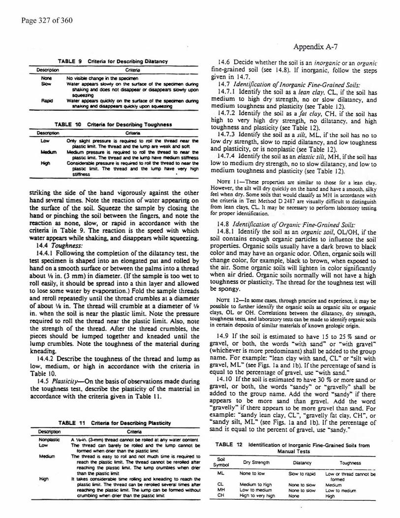


Page 332 of 360


Page 334 of 360


Page 338 of 360

Page 339 of 360

Page 340 of 360

Page 341 of 360
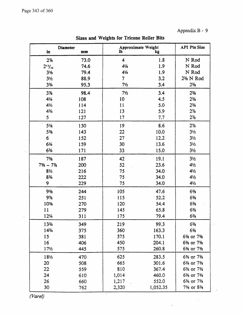

Page 344 of 360


Page 346 of 360


Page 348 of 360
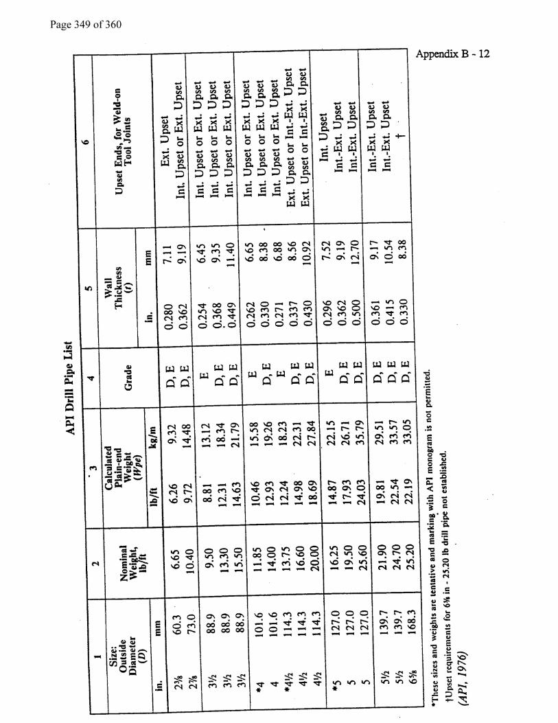

Page 350 of 360