chapter 12 state university of new york at …nsf-pad.bme.uconn.edu/2002/buffalo.pdf · chapter 12:...
TRANSCRIPT

CHAPTER 12 STATE UNIVERSITY OF NEW YORK AT
BUFFALO School of Engineering and Applied Sciences
Department of Mechanical and Aerospace Engineering 335 Jarvis Hall
Buffalo, New York 14260-4400
Principal Investigator: Joseph C. Mollendorf (716) 645-2593 x2319
5
117
118 NSF 2002 Engineering Senior Design Projects to Aid Persons with Disabilities
ADAPTIVE VIDEO GAME CONTROLLER Student Designer: Peter T. Streit
Supervising Professor: Dr. Joseph C. Mollendorf Mechanical and Aerospace Engineering Department
State University of New York at Buffalo, Buffalo, NY 14260
INTRODUCTION This project addresses the problem that children with disabilities face when using video game controllers with many small buttons. Some clients do not have the motor skills required to use many toys traditionally used by other children the same age. Playing video games will help these children develop better motor skills and hand-eye coordination.
SUMMARY OF IMPACT With this device, children now have the capability of playing a video game. They can also play with and compete against others.
TECHNICAL DESCRIPTION This project is based on the game “Sonic the Hedgehog” for the Sega Genesis. This is a simple game that consists of a character running and jumping. Once properly set up, the game can be controlled by only two buttons on the video game controller.
Almost any child could use this controller. Since each added button is run in parallel from the original controller, either the original controller buttons or the auxiliary larger buttons can be used. This allows the game to be adapted to different children and also allows another person to play with that child.
To keep this device versatile, the added larger buttons are connected to a headphone type plug on the front of the original controller. Fig. 12.1 shows
this connection. The universal connection allows each child to use his or her own button, with a choice as to the part of the game to operate (i.e., making the character run or jump).
The device was designed by using the original controller and adding two headphone jacks on its face. This allows the original controller to be used without modification or it can be adapted with additional larger buttons. When using the added larger buttons, the controller is still completely functional as before but there are additional wires from that headphone jack to the added buttons.
With the intricacies of the controller’s circuit board, a way to connect a parallel circuit before the main processor that is attached to the circuit board was needed. The best way was to connect the circuit close to where the original buttons were on the controller.
A small hole was drilled in the circuit board through the positive side of the circuit path; this was done to separate the paths. A ground was made at a common ground to keep it from interfering with the other circuit paths. Fig. 12.2 shows how the connections were made.
An area on the face of the controller offered the space required to mount the headphone jacks. Holes were drilled for the jacks and routed the wires so that could the controller faceplate and backing plate could be reattached when finished.
The total cost of this project was $25.

Chapter 12: State University of New York at Buffalo 119
Figure
Figu
12.1. Controller with Auxiliary Button.
re 12.2. Circ
uit Connections Inside the Controller.

120 NSF 2002 Engineering Senior Design Projects to Aid Persons with Disabilities
BI-FOLDING REFRIGERATOR DOOR TO FACILITATE ACCESS
Student Designers: Ben Kaye, Paul Near, and Kenneth Class Supervising Professor: Dr. Joseph C. Mollendorf
Mechanical and Aerospace Engineering Department State University of New York at Buffalo, Buffalo, NY 14260
INTRODUCTION This project addresses problems that affect people in wheelchairs, on crutches, using walkers or having any general mobility problem. People with such mobility problems have difficulty trying to accomplish a task while moving. One result of this problem is the difficulty in opening a refrigerator door while standing in front of the refrigerator. A standard refrigerator has a large opening radius for the door as shown in Fig. 12.3. As a result, the door cannot be opened while a person is still standing in front of the refrigerator.
SUMMARY OF IMPACT By taking a regular refrigerator and implementing a bi-folding door, the turning radius of the refrigerator door was drastically reduced. As a result, a person with a mobility problem will be able to stand in front of the refrigerator and open the door without having to move at the same time. In addition, other points were considered such as making sure that the shelving could slide out towards the person, and the controls for the refrigerator were not located in the back (as they most often are). This modification allows the refrigerator controls to be adjusted without much effort.
TECHNICAL DESCRIPTION The design that was considered took advantage of the existing door on the refrigerator. This door was converted into the bi-folding door by cutting the original door in half and then placing a hinge on the center of it. Since the door folds in the center, it is
important that to not have any gaps that would allow cold air to leak out. Another basic requirement of the design was to make a track to guide the door as it was opened and closed; the track was constructed from aluminum with two aluminum brackets welded to it. Figures 12.4 and 12.5 show the opened and closed bi-folding refrigerator door.
Figure 12.3. Standard Refrigerator Door.

Chapter 12: State University of New York at Buffalo 121
Another essential part of the design was the seals of the refrigerator door. Since the door is bi-folding, the seals could no longer be attached to the inside of the door because the seals would not allow for the door to fully open. New seals were designed and attached to the face of the refrigerator itself. The door closed against the magnetic strips that were placed on the seals. This prevented cold air from leaking out of the refrigerator. Seals were also placed in the seam of the bi-folding door so that when the door closed, air would not leak out through the center of the refrigerator.
The total cost of this project was $327.
Figure 12.5. Closed Bi-folding Door.
Figure 12.4. Opened Bi-folding Door.

122 NSF 2002 Engineering Senior Design Projects to Aid Persons with Disabilities
BOTTLE TWISTER ASSISTER: A DEVICE TO ASSIST PERSONS WITH LIMITED USE OF HANDS
TO OPEN TWIST BOTTLES. Student Designer: Jonathan A. Terrance
Supervising Professor: Dr. Joseph C. Mollendorf Mechanical and Aerospace Engineering Department
State University of New York at Buffalo, Buffalo, NY 14260
INTRODUCTION A large number of people have limited to no use of their hands. This category of people includes the elderly and those with conditions such as muscular dystrophy, cerebral palsy, and arthritis. This design problem is to create an assistive device that would alleviate some limitations that the individuals face. The major focus of this design project is to create a device to assist people in opening twist top soda bottles or other similar type bottles. The design is to be simple and lightweight so that a person can use it with ease. An assumption for this project is that the person operating the device has enough use of their hands to hold a bottle while handling the device.
SUMMARY OF IMPACT The impact of this device is that it will ease the everyday frustrations that people encounter when attempting to open twist type bottles. By doing so, it will satisfy the need for self-reliance and increase the confidence of the user. The simplicity of this design will allow for a practical and user-friendly device.
TECHNICAL DESCRIPTION Three designs were considered, however each one uses the same general concept similar to that of a candlesnuffer. Each device utilizes a cupping device that fits over the cap of the bottle. Along the inner surface of the cupping device are sharp radial teeth that allow a strong grip on the bottle cap once a torque is implied. The concept resembles that of a common nutcracker-like bottle-opening device that has a split handle which wraps around the bottle cap.
The first design is a single handle device that increases the torque generated by the twisting motion used to open the bottle. The handle is made of a solid aluminum shaft to decrease the weight of the device. The cupping device allows for the
handle shaft to slide, providing various lever arm distances. Upon application of a perpendicular force to the lever arm, an increased torque due to the long lever arm is generated, and the bottle opens with ease. The lever arm also contains an ergonomic handle to allow a better hold of the device. The T-bar configuration of the slider arm aids users who cannot close their fingers around the bottle cap when opening a bottle; this configuration allows for a better grip.
The second and third designs also contain the cupping feature used to grip the bottle cap. However, these designs contain different handle concepts than that of the first design.
The second design uses a thick foam padding that is added to the outer surface of the cupping mechanism. The purpose of the foam is to create a larger grip diameter around the bottle cap. This extension creates a larger, more comfortable grip around the small bottle cap that is often a source of frustration. This design is more compact and convenient than the first design; however it does not offer as much torque when opening a bottle.
Figure 12.6. Three Bottle-Opening Designs.

Chapter 12: State University of New York at Buffalo 123
Finally, the third design is generated using the same concept as the first through the use of an extended handle shaft. However, the handle for this design features a ratchet mechanism attached to the cupping device. The ratchet feature decreases the range of torque motion required to open the bottle, thus making it more convenient for users with limited hand motion. Similar to the second design, the shaft of the ratchet also contains foam padding as well as a strap; the strap is placed over the users hand to facilitate a stronger grip. The ratchet design also features the cupping device as a detachable part similar to a socket attachment of a socket wrench. Thus, this device can be used as a regular socket wrench that has a more padded comfortable grip and a secured adjustable strap.
Fig. 12.6 shows all three device designs. Starting at the top moving counterclockwise is the sliding handle shaft design, the compact padded handle-less design, and the ratchet handle design.
The torque generated by this device is a function of the radial position of the input force multiplied by the input force of the user. Without the use of this device, the torque generated to twist the bottle cap would simply be the radius of the bottle cap times the input force, as shown in Fig. 12.7a. Using a device with a lever arm to twist the bottle cap increases the torque generated by a factor of the ratio of the extended radial distance to the radius of the bottle cap shown in Fig. 12.7b.
For the first design, utilizing a sliding handle shaft allows for a range of torques to be generated using the same input force. The sliding handle shaft mechanism consists of a bearing and spring interaction which lock into small radial grooves along the handle shaft. The location of these grooves determines the torque generation factor. An
average bottle top radius is determined experimentally and is approximately 0.06025 inches. Using this specification and the torque ratio equation, various torque factors are determined.
To accommodate different types of bottle caps, the cupping device has an angled edge. A straight (90°) angle will only fit one bottle cap size. However, if the angle is reduced slightly, the cupping device can accommodate a variety of bottle cap sizes. It should be noted that the angle must be straight enough to maintain enough grip to turn the cap. An edge angle of 81° is found to be optimal to accommodate various bottle cap sizes.
The total cost required to implement these design models was approximately $30.
F
r Tr = F r
Figure 12.7a. Torque Required to Open Bottle.
F
RTr = F r
TR/Tr = (R/r) F
Figure 12.7b. Calculation of Torque Ratio Factor.

124 NSF 2002 Engineering Senior Design Projects to Aid Persons with Disabilities
DOOR LEVER: A DEVICE TO FACILITATE EASIER OPENING OF DOORS THAT USE A KNOB
Designers: Dennis P. Brady and Bryan C. Silverblatt Supervising Professor: Dr. Joseph C. Mollendorf
Mechanical and Aerospace Engineering Department State University of New York at Buffalo, Buffalo, NY 14260
INTRODUCTION Twisting a doorknob poses a significant challenge to many people. An adapter that transforms a doorknob into a lever is was designed. This mechanism utilizes a large moment arm and a self-locking design to transform the twisting motion of the hand into a larger, linear, action of the arm that effectively converts a doorknob into a door lever.
SUMMARY OF IMPACT An assistive device was designed to convert the twisting action used to open a doorknob into the movement of a lever. The user will be able to turn a doorknob, utilizing the increased leverage created by our device, with a subsequently easier and broader motion. The system of links squeezes harder on the doorknob as the moment arm is pushed downward, ensuring its grip as rotation begins. The design also does not interfere with the doorframe, as it has a low profile around the doorknob. Overall, this device will provide an easier experience for those who have difficulties turning doorknobs.
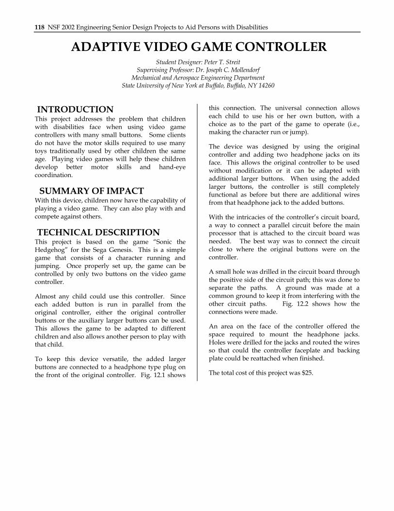
TECHNICAL DESCRIPTION By pushing the doorknob into the joint, between the flat and angled inner edges of the mechanism, the device closes in upon itself. As the mechanism is pushed in further, or as the handle is moved downward around the doorknob, the device closes in with greater force and uses friction to create a firm grip. The inner edges of the device are lined with rubber to further ensure this.
Many aspects were considered in the design process to ensure practicality and reliability. The final design for this device has the following features.
Self-locking – The device locks itself on the doorknob and does not rely upon the strength and ability of the individual. By design, the device grabs
onto the doorknob and uses friction to ensure a solid grip throughout the entire movement.
Lightweight – The device is formulated from polycarbonate. This material makes it strong, durable, and lightweight. This facilitates the ease in which it can be used by those with limited strength as well as making it portable.
Easy to Use – The handle of this device is placed as far away from the doorknob as possible to allow maximum leverage without being cumbersome to the user.
Compatibility – This device works for various doorknob sizes. There are no restrictions imposed on its movement by the door jam, doorframe, depth or shape of the doorknob.
Functionality – The device works for doorknobs located on the left and right hand sides of the door. There are also implications for use in other twisting motion applications (i.e. opening and closing jars and other similar items).
Aesthetics – In order to promote the marketability of the mechanism, aesthetics were considered. The
Figure 12.8. Opened Device.
Chapter 12: State University of New York at Buffalo 125
design and material used are selected such that our device is not intimidating or complicated.
When closed, the device has no open holes, gaps, or pinch points, which may cause a safety concern. The dimensionality of the design has been extended so that it closes in upon itself and maintains the same thickness throughout the mechanism. The project has been formed with three layers of 0.25-inch sheets of polycarbonate, and cemented together for thickness as needed. Pins in the joints also serve to insure that the layers maintain alignment, as well as provide mobility.
The total cost for the device was $44.
Figure 12.9. Device in Use.
126 NSF 2002 Engineering Senior Design Projects to Aid Persons with Disabilities
THE E-Z SEAT LIFTER: A MECHANICAL DEVICE TO ASSIST IN LIFTING AND LOWERING A
LAVATORY SEAT Designers: Wendy McKenzie and Mark Newman
Supervising Professor: Dr. Joseph Mollendorf Mechanical and Aerospace Engineering Department
State University of New York at Buffalo, Buffalo, NY 14260
INTRODUCTION The E-Z Seat Lifter is a device designed to assist the elderly and disabled with using the lavatory. The objective of this project is to allow people to lift and lower the lavatory seat without bending or overexerting their backs. The device is adjustable and can be applied to a variety of household toilets.
Once the E-Z Seat Lifter is installed, it will convert a small force into the complete routine motion of lifting and lowering the seat and cover. The use of a foot to apply the force makes for easy operation.
SUMMARY OF IMPACT This device could improve functionality for the elderly or those with back problems. The addition to the market of a safe, easily functioning, and practical device would be a benefit to many.
Considerations in the design and construction of the E-Z Seat Lifter were size, aesthetics, durability, adjustability, and most importantly, cost. The E-Z Seat Lifter is constructed with an inexpensive budget to make it affordable for everyone.
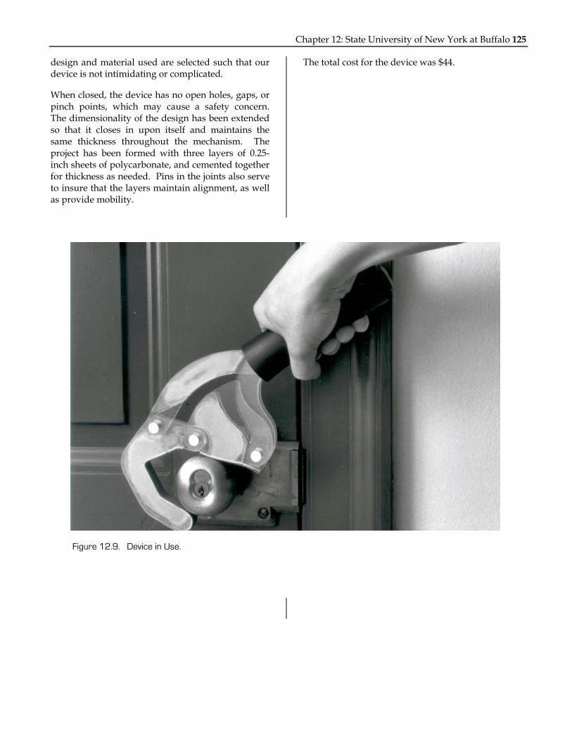
TECHNICAL DESCRIPTION The E-Z Seat Lifter is an assistive device that uses a foot pedal to mechanically lift the seat and lid of the lavatory. The frame of the device is made of stainless steel and aluminum. The lever is a metal plate (attached to the ground) with a pivot connection where a T-shaped aluminum bar is attached. The foot pedal is at one end of the T shaped aluminum bar, and a pivoting aluminum rod is at the other. Both the aluminum bar and the rod have various holes drilled at the connection points. These holes allow the mechanism to be adjusted so that it can be used on a wide variety of lavatories. The aluminum bar is fastened to a clevis joint and threaded rod. This is drilled into the
ss
Tcsftc
Figure 12.10. E-Z Seat Lifter in Upright Position.
tainless steel rod, which supports and rotates the eat and cover.
he seat and cover are plastic and handicap ertified. The cover can detach from the stainless teel bar and the seat can then be easily unscrewed rom the lavatory. This feature allows adjustments o be made to the seat and lid. It also makes leaning the device and surrounding area simple.
Chapter 12: State University of New York at Buffalo 127
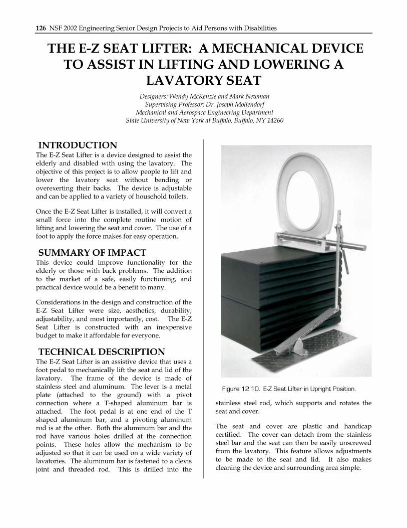
The device is placed to the side of the toilet. It sits in an obscure area where it does not obstruct the path of traffic or take up excessive space. While the majority of seats on the market are standard, two-piece hinged lids, the E-Z Seat Lifter offers an inexpensive, helpful alternative to the norm.
The overall cost of production was $47.
Figure 12.11. E-Z Seat Lifter in Closed Position.

128 NSF 2002 Engineering Senior Design Projects to Aid Persons with Disabilities
THE GROCERY LIFTER: A DEVICE TO AID THE REMOVAL OF HEAVY OBJECTS FROM THE TRUNK
OF A CAR Student Designers: Jim Vrana and Steven Spagnolo
Supervising Professor: Dr. Joseph C. Mollendorf Mechanical and Aerospace Engineering Department
State University of New York at Buffalo, Buffalo, NY 14260
INTRODUCTION The goal in designing the Grocery Lifter is to develop a lifting system to help remove heavy items from the trunk of a car. There are several technical issues that must be addressed in designing such a product. First and foremost is safety. The device must not contain any sharp edges, have a limited number of pinch points, and the load must be secured on the device. In order to make the device durable and long lasting it must be able to exceed its recommended lifting capacity and be constructed to have adequate strength. Finally a power source is
needed that will not only lift the load, but lift it in a reasonable amount of time.
SUMMARY OF IMPACT The specific technical goal is to design the Grocery Lifter to raise a load of 200 pounds a vertical distance of 18 inches in under 20 seconds. This device will aid those who have difficulties lifting due to bad backs or other disabilities.
The design challenge is to find a motor that will provide the optimal torque to lifting rate ratio that
Figure 12.12. The Grocery Lifter in Open Position.

Chapter 12: State University of New York at Buffalo 129
will meet the requirements of the project. Aluminum is used to build the device since it is high strength and low-weight. Since the lift is to be installed in the trunk of a car, the easiest source of power to use is from the car battery itself.
TECHNICAL DESCRIPTION A single-shaft 12 Volt DC motor is placed in the center of the trunk and is used to turn an ACME threaded rod. When the motor is turned on, the rod turns through a nut that is connected to two bars that stem out from each side of the nut and run perpendicular to the rod. Each bar is connected to a sliding end of a pair of scissor type mechanisms at the base of the device. The scissors are connected at each end to 80/20 aluminum channels. Each pair of scissors has two fixed ends in the rear of the device and two ends that slide from front to back. As the scissors are slid from front to back by the rod, the table raises and lowers. A top plate is connected to the two pairs of scissors, creating a platform for objects to be raised and lowered on. Limit switches are used at the highest and lowest point to limit the travel of the top plate.
The goal of lifting a load a desired height within a certain time given power restraints has been met. The Grocery Lifter is an effective method for aiding
in the removal of heavy objects from the trunk of a car. It has been built with durability, longevity, and safety in mind. Also, it can be easily installed in the trunk of a car and enables the trunk to remain functional when the lifter is not in use.
The total cost of this project was $700.
Figure 12.14. The Lifting Mechanism.
Figure 12.13. The Grocery Lifter in Closed Position.

130 NSF 2002 Engineering Senior Design Projects to Aid Persons with Disabilities
THE MELT MASTER: A DEVICE TO FACILITATE SALTING OF RESIDENTIAL DRIVEWAYS
Student Designers: Jean-Michel Thiers and Tuan Nguyen Supervising Professor: Dr. Joseph C. Mollendorf
Mechanical and Aerospace Engineering Department State University of New York at Buffalo, Buffalo, NY 14260
INTRODUCTION During icy winter days people often spray salt on the driveway to melt the ice so it is not slippery when walking. It is unsafe for those persons with disabilities to walk or use their wheelchairs on icy pavement. The Melt Master is a device that will allow a person to spray the driveway with ice without having to move.
SUMMARY OF IMPACT The Melt Master is to be placed at a fixed location that will allow the user to spray salt over the driveway from that fixed point. This will allow a person to spray salt on the driveway fairly easily
and without needing to move. The salt sprayer is mounted at the end of a leaf blower motor, which will reduce the cost of the salt sprayer. The person can use the leaf blower to blow leaves during the fall and in the winter for the Melt Master. The Melt Master was tested to spray salt as far as 15 yards.
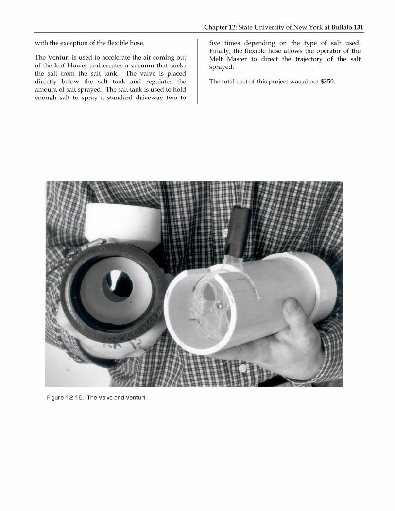
TECHNICAL DESCRIPTION After removing the nozzle from the motor of the leaf blower, this motor can be installed into the Melt Master frame. The leaf blower motor is used since it operates on the same concept as the Melt Master. The Melt Master nozzle is composed of a venture, a valve, a salt tank, and a flexible spray hose. These components are displayed on the picture below,
Figure 12.15. The Melt Master with Frame.
Chapter 12: State University of New York at Buffalo 131
with the exception of the flexible hose.
The Venturi is used to accelerate the air coming out of the leaf blower and creates a vacuum that sucks the salt from the salt tank. The valve is placed directly below the salt tank and regulates the amount of salt sprayed. The salt tank is used to hold enough salt to spray a standard driveway two to
five times depending on the type of salt used. Finally, the flexible hose allows the operator of the Melt Master to direct the trajectory of the salt sprayed.
The total cost of this project was about $350.
Figure 12.16. The Valve and Venturi.

132 NSF 2002 Engineering Senior Design Projects to Aid Persons with Disabilities
THE SERVO CONTROLLED ROBOTIC ARM: A DEVICE TO AID IN MOVING OBJECTS
Student Designer: Daniel D’Alfonso Supervising Professor: Joseph C. Mollendorf
Technical Advisors: Roger Krupski and William Willerth Mechanical and Aerospace Engineering Department
State University of New York at Buffalo, Buffalo, NY 14260
INTRODUCTION The goal of this project was to design and build a robotic arm that would assist people in wheelchairs to move objects from one location to another. It was also a goal to design an inexpensive and simple system that could be used by anyone. The robotic arm that was designed for this project has many low cost yet functional qualities.
The device is intuitive and easy to operate, requiring little to no training. It is also adaptable to a wide variety of controller types (i.e. joysticks, puff-switches, microprocessors, speech recognition systems, etc.). The functionality and flexibility of this device makes it suitable for a wide range of users and user abilities. See Fig. 12.17.
SUMMARY OF IMPACT The robotic arm that is developed in this project will give people in wheelchairs greater independence and more mobility, enabling them to utilize time more effectively.
TECHINCAL DESCRIPTON The entire system can lift a maximum of one kilogram a vertical distance of 0.9 meters with a velocity ranging from 0.228-0.304 meters/second. The robotic arm itself is a 0.762 meter hollow aluminum rod with a 0.95 centimeter inner diameter. One 4.5 rpm, 12 volt, DC-motor with a 186W rating generates enough torque for both the static and dynamic loading conditions the device will undergo. Another similar motor is used as the gripper actuator to produce an estimated 0.0016N of gripping force. This allows for adequate gripping and holding power throughout the arm’s entire range of motion.
The gripping mechanism is a slightly modified mountain bicycle brake caliper. The brake pads can be rotated to provide the optimal gripping
configuration. The gripper is connected to the DC gear motor via an aluminum pulley, bicycle brake cable, and cable housing. The configuration of the brake housing ensures that the cable will not slip off of the pulley in addition to guiding it properly. In its current configuration as shown in Fig. 12.18, the gripping mechanism is able to pick up objects such as perfectly flat sheets of paper, dimes, cordless
Figure 12.18. The Gripping Mechanism.
Figure 12.17. Servo Controlled Robotic Arm

Chapter 12: State University of New York at Buffalo 133
phones, and clothing.
From the outset it was decided that only a ‘proof of concept’ device would be built instead of a full-scale version. This helped save money while still allowing the designers address all the technical issues of a full-scale model. Fig. 12.19 shows a possible location where the servo-controlled robotic arm can be affixed. The design is flexible enough to allow multiple attachment arrangements. Other features, such as a collapsible arm, would make storage of the robotic arm more convenient.
Servo-Motor Controller Description The servo motor controller is built around a Motorola MC33030 DC Servo Controller integrated circuit (chip). Because the power requirements of the robotic arm exceeded the drive capability of the chip, an H-Bridge power amplifier is added between the controller chip and the motor. The H-Bridge circuit is designed to provide current feedback information to the controller chip to allow the over-current and braking functions to continue working while greatly boosting the drive capability of the servo circuit.
Servo Motor Operation A DC gear motor is coupled to the robotic arm via an aluminum hub; also attached to this hub is a feedback potentiometer, this is shown in Fig. 12.20. The potentiometer provides position feedback information to the servo controller chip. The robotic arm is positioned by applying a control voltage to the servo controller chip. Depending on the applied voltage, the motor will rotate the arm, up or down, as required such that the output of the feedback potentiometer matches the control input. The controller chip also provides a dead band so that the robotic arm does not “hunt” or oscillate around the desired point due to mechanical inertia. Since the servo controller chip input is a simple DC level, it is easily adaptable to a wide range of controls such as a joystick, a puff switch, or even a microcontroller. The very low voltage DC control signal (0 to 5 volts) also makes the system inherently safe for the user.
Safety Features The servo controller incorporates several safety features to protect both the user and the robotic arm itself. The most important safety feature of this controller is programmable over-current protection. The robotic are is designed to lift a maximum mass of one kilogram. This mass, along with the moment
artmmsTsfmmntt
T
Figure 12.19. Representation of Mounting Placement.
rm of the aluminum tubing, defines a torque equirement for the servomotor. This, along with he motor specifications, allows the selection of a
aximum permissible motor current. This aximum current value is programmed into the
ervo controller circuit via a current limiting resistor. his protection scheme not only protects the servo ystem from an overload, it also protects the user rom injury by limiting the output torque of the
otor. The servomotor itself is chosen so that its aximum output torque does not exceed what is
eeded. As a result, even if the safety circuit failed, he motor would be incapable of damaging itself or he user.
he entire project cost was $110.00.
Figure 12.20. Servo Motor Setup.

134 NSF 2002 Engineering Senior Design Projects to Aid Persons with Disabilities
SILENT ALARM SYSTEM FOR INDIVIDUALS WITH HEARING IMPAIRMENT
Student Designer: Scott Seyfried Supervising Professor: Dr. Joseph C. Mollendorf
Mechanical and Aerospace Engineering Department State University of New York at Buffalo, Buffalo, NY 14260
INTRODUCTION Waking up to an alarm clock is one of the everyday liberties that most people take for granted. Individuals with a hearing disability may not be able to be wake up with standard alarm clocks. For this reason, a device was created that uses the sense of touch, rather than hearing, to wake such an individual.
The device created employs a microphone to detect the alarm and a circuit that uses the input from the microphone to switch on a vibrating motor. The vibration from the motor is the sensation that wakes the individual wearing the device.
SUMMARY OF IMPACT This device is an improvement over the many existing units. Some existing units use a strobe light to wake the user; however, this method may be ineffective depending on the person’s sleeping position. The use of a vibrating motor, connected directly to the person, eliminates this uncertainty.
The nature of this design makes the unit portable, as it functions with any standard alarm clock and can be made into a compact unit given further development. The device also has the added safety feature of waking the user in the case of a fire alarm.
TECHNICAL DESCRIPTION The major aspect of this design is the switching circuitry. The approach chosen was to use an op-amp circuit. An LM 324 quad op-amp chip is used for its high gain and its capability of running at low
R4 33kR210k
R11k
C110u
FMIC
0 0
R51k
C310u
F
V+
V-11
1
R6 33k0
C510u
F
R10 100
R71k
D1N914
0
R310k
0
C21uF
0
C21uF
0
R310k
2OPAMP
3OPAMP
4OPAMP
R91.5k
0
Motor+9V
Figure 12.22. Circuit Schematic.
Figure 12.21. Unit Packaged on Wristband.
Chapter 12: State University of New York at Buffalo 135
voltages.
The microphone chosen is a condenser microphone element. The microphone supply voltage range is between 1.5 and 10 volts. A nine volt power supply is used to accommodate both the op-amp chip and the microphone.
First, the signal from the microphone must be amplified so that it can be used to switch on the motor. This is done using the first two op-amps on the chip, rather than just one, to ensure that the amplification levels are at safe values. The output of the Microphone is coupled via a 10 uF capacitor, to block the AC signal, and to a 1K ohm resistor. The signal from the 1K resistor is passed to the negative side of the first op-amp, and a 33K feedback in order to set the gain at 33. A half and half circuit containing two 10K resistors sets the reference voltage at 4.5 volts to the positive side of op-amp one. In addition, a 0.1 uF capacitor is placed from the half and half circuit to ground in order to stabilize the circuit.
The output of the first op-amp is passed through a 10 uF capacitor and then through a 10K resistor. This resistor is passed into the negative terminal of the second op-amp, and with a 33K feedback resistor, resulting in another gain of 33. This results in an overall total gain for the circuit of approximately 1089. The second op-amp is referenced to the positive side of op-amp one.
Now that the signal has been amplified, a third op-amp is used as a comparator to detect the voltage increase when the microphone detects the alarm. An IN914 diode and a 1K resistor at the output of op-amp two reduce the voltage by approximately 0.77 volts; this sets a difference between the comparator’s reference signal and the input signal. The input signal is connected to the positive side of op-amp three. The comparator then gives an output when the signal is raised above the reference, which travels from the negative terminal of the op-amp to the positive side of op-amp two.
Just before the comparator, it is necessary to put in a filter to reduce background noise so the device is only triggered when a large signal is detected. The filter is placed after the 1K resistor and is composed of a 470K resistor and a 10 uF capacitor, wired in parallel, from the 1K resistor to ground.
Tcodviattatcv
Alrr
Tfrrao
Tsttpbts
T
Figure 12.23. Internal Circuitry.
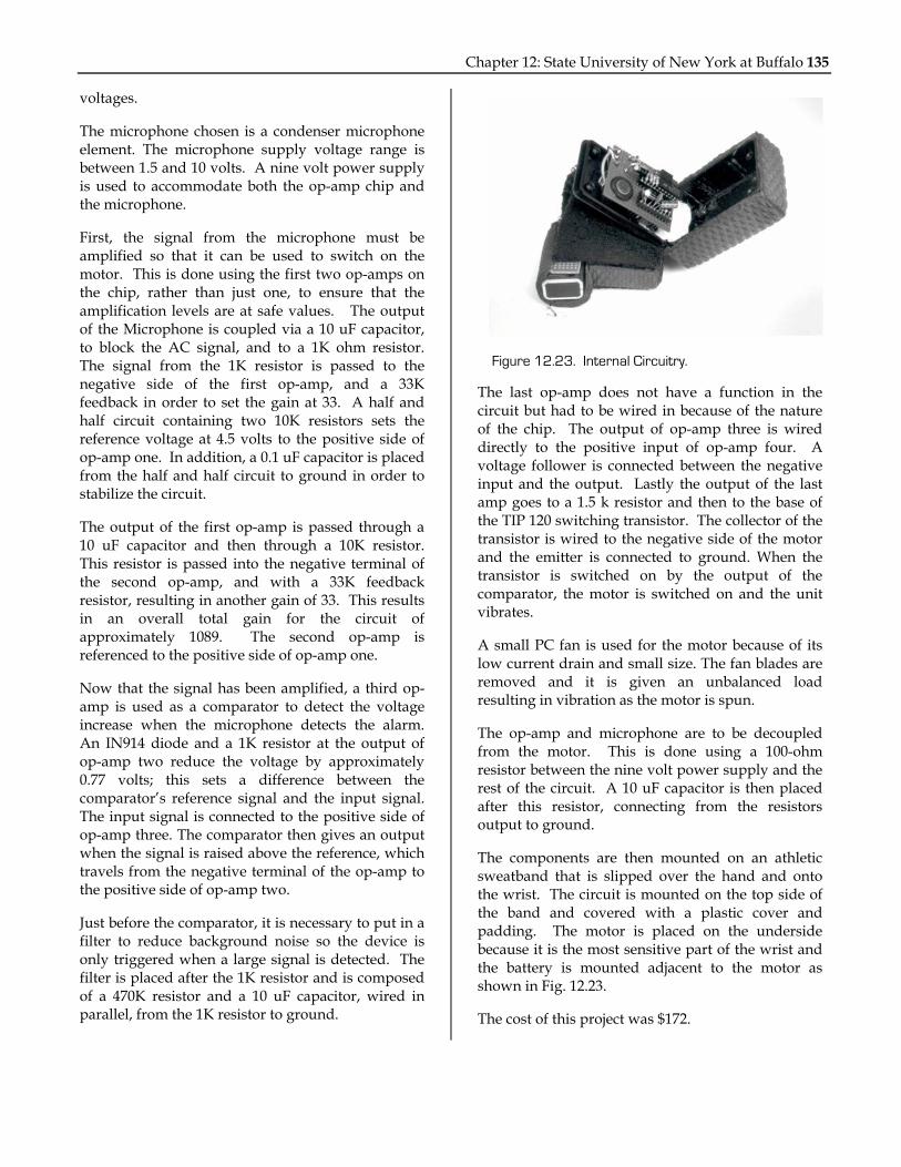
he last op-amp does not have a function in the ircuit but had to be wired in because of the nature f the chip. The output of op-amp three is wired irectly to the positive input of op-amp four. A oltage follower is connected between the negative
nput and the output. Lastly the output of the last mp goes to a 1.5 k resistor and then to the base of he TIP 120 switching transistor. The collector of the ransistor is wired to the negative side of the motor nd the emitter is connected to ground. When the ransistor is switched on by the output of the omparator, the motor is switched on and the unit ibrates.
small PC fan is used for the motor because of its ow current drain and small size. The fan blades are emoved and it is given an unbalanced load esulting in vibration as the motor is spun.
he op-amp and microphone are to be decoupled rom the motor. This is done using a 100-ohm esistor between the nine volt power supply and the est of the circuit. A 10 uF capacitor is then placed fter this resistor, connecting from the resistors utput to ground.
he components are then mounted on an athletic weatband that is slipped over the hand and onto he wrist. The circuit is mounted on the top side of he band and covered with a plastic cover and adding. The motor is placed on the underside ecause it is the most sensitive part of the wrist and he battery is mounted adjacent to the motor as hown in Fig. 12.23.
he cost of this project was $172.

136 NSF 2002 Engineering Senior Design Projects to Aid Persons with Disabilities
THE SOCKMATE: AN ASSISTIVE DEVICE THAT HELPS PEOPLE PUT ON THEIR SOCKS
Student Designer: Patrick J. Mann Supervising Professor: Dr. Joseph C. Mollendorf
Mechanical and Aerospace Engineering Department State University of New York at Buffalo, Buffalo, NY 14260
INTRODUCTION A reliable, convenient, easy to use dressing aid has wide appeal to the millions of people who have chronic back pain. Any degree of immobility caused by back pain can affect an individual by making even the simplest of tasks difficult to perform. Something as mundane as putting on a pair of socks becomes a time consuming and painful chore. Since people have to get dressed in order to go about their daily lives, there is a need for a device that can either reduce the pain or allow an individual who has back pain to avoid it all together. A device to move the sock in close proximity and line up with the foot
eliminates the need for the person to bend over. The device is non-destructive to clothing and free of any pinch points or snags. It is also suitable to accommodate a wide range of foot sizes.
SUMMARY OF IMPACT The SockMate makes it possible for people who have chronic back pain to get dressed with ease by eliminating the need to bend over. The device allows socks to slip on with minimal effort and discomfort. This device can be of great benefit to back surgery patients because it gives them the ability to get dressed without the pain they would
Figure 12.24. The SockMate.

Chapter 12: State University of New York at Buffalo 137
otherwise experience.
TECHNICAL DESCRIPTION The boot of the SockMate is made from a flexible piece of molded thermoplastic. The flexibility of the material allows several different sock sizes to be used. A single adjustable handle is attached to the back of the boot. The handle is a two-piece aluminum pole that is tapered toward the bottom. The inside diameter of the lower part of the pole is 0.75 inches and the outside diameter of the top part of the handle is 0.75 inches with a clearance of 0.01 inches. This ensures that the handle can be adjusted to accommodate people of all heights while either standing or sitting. Eight holes, spaced an inch apart, are drilled into the lower part of the handle. A spring-loaded pin that fits into any of the adjusting holes is attached to the upper part of the handle. The pin fits into any of the adjusting holes and locks the upper part of the handle in place. At
the top of the handle is an ergonomic handgrip that maintains comfort during use.
The SockMate comes with a gripping system that keeps the sock from slipping off the device when pulling the sock past the heel and over the ankle. A lever, resembling a bicycle brake lever, is located at the top of the handle. A jacketed, thin braided wire cable runs from the lever down the pole where it connects to a pivoting gripper. Squeezing the lever operates the gripper by lifting it away from the sock. The gripper force is supplied by a spring that applies about ten foot-pounds of pressure on the upper rear of the sock in order to hold it against the boot upper. The contact surface of the gripper is a knobby rubber pad that will not harm the cloth of the sock. The gripper allows the boot to be easily pulled out of the sock as the lever is squeezed.
The overall cost to produce this prototype was $25.00.
Figure 12.25. Sock Attached to The SockMate.

138 NSF 2002 Engineering Senior Design Projects to Aid Persons with Disabilities
TAS-5000: THE TRUSTABLE ADJUSTABLE SINK Student Designers: Andrew Rybarczyk, Jonah Wojtanik
Supervising Professor: Dr. Joseph C. Mollendorf Mechanical and Aerospace Engineering Department
State University of New York at Buffalo, Buffalo, NY 14260
INTRODUCTION The Trustable Adjustable Sink, the TAS-5000, was designed and developed in order to assist individuals with disabilities with using a sink in their homes. A wooden sink base has been created that is fully height adjustable by means of an electric motor.
The sink is designed so that not only can an individual in a wheelchair roll up and under the sink, he can adjust the height of the sink/countertop to whatever height suits him. This adjustable design can accommodate any personal preference. This design can not only accommodate people with disabilities, but it could work for any individual. The adjustable aspect allows people to set and adjust the sink and countertop to a specific need.
SUMMARY OF IMPACT The sink was designed to not only help people with disabilities in a functional way, but in many parts is a different kind of assistive device. The aesthetics of this design are a major part of the project. Adjustable sinks on the market today lack the aesthetics that most people prefer. They are plain and simple, consisting of a sink basin, usually ceramic, mounted to a steel track mounted on the wall. This design looks to be a luxurious sink and counter, typically for use in a bathroom. The sink sits in a beautifully designed wooden cabinet base, which is fully adjustable. With the simple push of a switch the sink will raise and lower to the desired height.
In addition, not only does the sink raise and lower, the entire countertop of the wooden base also moves along with the sink. This design was found to be more useful than the competition’s use of a simple sink basin mounted to a track on the wall. With other designs, there is no countertop, it appears unpleasant, and the bathroom mirror, which is usually mounted to the wall behind the sink, is found to be useless to someone sitting in a wheelchair. This design has the ability mount a
cwa
OTmthm
Figure 12.26. The TAS-5000.
ountertop mirror to the wooden sink base itself, hich in turn would adjust right along with the sink
nd wooden base.
TECHNICAL DESCRIPTION ne other specific aspect that was redesigned for AS-5000 was the faucet handles. All sinks on the arket have the standard faucet handles located in
he rear of the sink. This design places the faucet andles on the front side of the wooden base to ake them more accessible and easy to use.
Figure 12.27. The Lifting Mechanism.

Chapter 12: State University of New York at Buffalo 139
The TAS-5000 operates on 120V ADC current, meaning it can be simply plugged into the wall. The entire wooden base and sink is self contained, so it does not require mounting to a wall or floor. The wooden sink countertop adjusts in height approximately 22 inches up to 36 inches above the ground. The adjustable sink is equipped for maximum safety, with two limit switches to cut the power when the sink reaches its maximum and minimum heights. It is also equipped with two limit switches attached to a safety bar. When the sink is being lowered and there is an obstruction under the sink, the safety bar will trigger and the power will be cut. This prevents anything or anyone from being crushed.
The lifting mechanism runs off a single chain drive system, using a 1/4hp electric motor, and four synchronized linear jacks. The system is also
equipped with a fuse to protect the user and the electrical system. The lifting mechanism is controlled from a simple, easy to use switch. The switch is momentary, therefore if the user lets go, the movement of the sink will cease. The sink countertop is capable of lifting approximately 300 pounds, which is done for safety of the users and device. The TAS-5000’s faucet handles are placed in the front of the sink base for easier access and use.
The overall cost of the TAS-5000 was approximately 40-50% less expensive, not including labor costs, to build than the competition’s ceramic sink basin on a steel track. The overall cost of the sink was approximately $710.
Figure 12.29. Chain Linkages.
Figure 12.28. Motor-Chain Drive System.

140 NSF 2002 Engineering Senior Design Projects to Aid Persons with Disabilities
TABLE PRO: A PORTABLE WORKING SURFACE FOR PEOPLE WHO USE WHEELCHAIRS.
Student Designer: Timothy F Barbour Supervising Professor: Dr. Joseph Mollendorf
Mechanical and Aerospace Engineering Department State University of New York at Buffalo, Buffalo, NY 14260
INTRODUCTION The objective of this project was to design and build a portable flat surface that could be utilized by anyone in a wheelchair. People in wheelchairs are constantly looking for a suitable working space to be used for work, school, or even just a place to eat. The Table Pro was designed to be custom fitted on a wheelchair to allow for easy access to a useable surface that would not prohibit the regular use of the wheelchair. Using an aluminum body and a carbon fiber tabletop, the Table Pro will have ample strength to hold regular everyday objects (i.e. a book or portable computer) with little effect on the
wheelchair itself.
SUMMARY OF IMPACT The Table Pro was built with the specifications based on the needs of an average person. The table was sized to be 16 x 16 inches, which is as wide and as long as an open text book. It is lightweight, collapsible, and can be used with a collapsible wheelchair. The Table Pro will make ample workspace available.
Figure 12.30. Mounted Table Pro.

Chapter 12: State University of New York at Buffalo 141
TECHNICAL DESCRIPTION The Table Pro is constructed with a piece of round aluminum stock and rectangular piece of aluminum stock welded together. The pieces are drilled with an inside diameter 0.001 inch- 0.003 inch larger than the outside diameter of the leg of the wheel chair. Then it is split in two directions, with a clamping hole drilled and tapped. When the screw is tightened, the inside diameter will decrease and squeeze the leg of the wheel chair. The flat surface has a ball bearing place inside to allow for a full three sixty-degree rotation around the table leg. The aluminum arm is then mounted to the base using a 5/8 inch bolt with a washer and lock nut to prevent them from separating. There are two indentations
strategically placed in the base that allow for the arm to lock in place by utilizing a spring pin. The arm is custom fit so the length of the arm is equal to the width of the back of the particular wheel chair. The arm has a rectangular flat plate at the end that allows for a more equal load transfer from the table to the arm of the chair, helping to keep the table rigid. A hinge is mounted to the plate to allow for the table to fold for minimal space consumption when the wheel chair is folded. The table is a carbon fiber molded table that allows for a higher strength /weight ratio with an aluminum base.
Total cost of project was $250.00.
Figure 12.31a. Collapsed Table Pro.
.425
1.160
3.000
1.000
2.000
.05 SLOT
.25
1.00 1.25
.25
.25
.50
7/16 DIA. C'BORE .50 DEEP1/4 - 20 UNC THRU HOLE
1.25
3.00
3.50
5.00
1.50
.425 DIA.720 DIA.
.880 DIA.
1.91 DIA.
Figure 12.31b. Schematic of Mount.
142 NSF 2002 Engineering Senior Design Projects to Aid Persons with Disabilities
WHEELCHAIR WHIRLIGIG: A DEVICE TO HELP PEOPLE IN WHEELCHAIRS TURN AROUND IN AN
ELEVATOR Student Designers: Di Song, Brian J. Wells, and Daniel R. Keating
Supervising Professor: Dr. Joseph C. Mollendorf Mechanical and Aerospace Engineering Department
State University of New York at Buffalo, Buffalo, NY 14260
INTRODUCTION This project addresses a problem that affects wheelchair-restricted individuals using an elevator. Once inside the elevator, the individual must go back and forth in small increments in order to turn around 180 degrees so they can face the elevator door upon exiting. This can be even more difficult in small elevators or when there are other individuals present in the elevator. The Wheelchair Whirligig is specifically designed to aid the individual in turning around 180 degrees with a minimal space requirement.
Many devices to solve this problem have been devised over the years, not one that is designed for use in an elevator. Several designs were evaluated; one particular design was chosen.
For the device to be effective, the following guidelines are set. It must be able to operate with a load of up to 600 pounds, have a low profile, sturdy construction, operate on AC voltage from the elevator power supply, start and stop at precisely 180 degrees, tamper resistant (device locks if someone tries to turn it manually), and can only be operated by the person in the wheelchair. The device is also to be built into the elevator floor, so having a low profile is very important. For safety reasons during operation, wells are cut into the top surface for the wheelchair wheels to dip into, so the wheelchair will not slide as the device rotates.
SUMMARY OF IMPACT This device is not only beneficial for individuals in wheelchairs, but also beneficial to factories and plants. The whirligig can be used in rotating pallets of raw materials in cargo elevators. This can save the operator a lot of time and cut costs for the factory. It also eases the strain on the operator when compared to having to move the pallets manually.
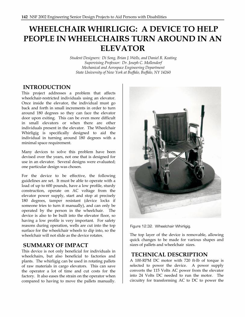
Figure 12.32. Wheelchair Whirligig.
The top layer of the device is removable, allowing quick changes to be made for various shapes and sizes of pallets and wheelchair sizes.
TECHNICAL DESCRIPTION A 100-RPM DC motor with 720 ft-lb of torque is selected to power the device. A power supply converts the 115 Volts AC power from the elevator into 24 Volts DC needed to run the motor. The circuitry for transforming AC to DC to power the

Chapter 12: State University of New York at Buffalo 143
motor and the timing device used to ensure a 180-degree turn detailed in Fig. 12.33.
The output speed is reduced from 100 RPM to 5 RPM in order to perform a half rotation in six seconds. The speed reduction is achieved by utilizing a worm gear and worm. The worm gear is chosen because of its ability to prevent motion in the opposite direction. This satisfies one of the safety concerns addressed earlier. To make sure that the rotation stops at 180 degrees, a timer is utilized in the circuitry to provide power to the device for approximately six seconds. A 20-tooth worm gear and a six-tooth worm are used. The worm is attached to the keyed output shaft of the motor while the worm gear is attached to a four-bolt flange mount with self-aligning bearings via a keyed shaft. The keyed shaft is then connected to the rotating platform through a self-made keyed mount. The mount is then attached to the rotation platform. The rotating platform sits on a four-foot diameter ring lined with bearings that enable it to rotate; the platform has a profile of only one inch (see Fig. 12.34). The electrical component is placed on the top of the elevator while the mechanical components are placed under the floor of the elevator.
The motor, bearing, gears and electronic components are purchased from various companies. The body of the device is constructed out of wood. Wood was chosen because of its weight, cost, and ease of modification. Paint was applied to the wood for aesthetic purposes.
Acknowledgements are made to Kenneth Peebles and Bill Macy for their assistance in machining and
welding.
The total cost of this project was $822.
Fuse
Fuse
MotorStarter Relay
AuxContact
115 VAC
115 VACto
24 VDCConverter
24 VAC
AuxRelay
Timer
TimerContact
SwitchFus
e
MotorStart
Contact
Fuse
MotorStart
Contact
Motor
Figure 12.33. Motor Control Schematic.
Figure 12.34. Mechanical and Electrical Assembly.

144 NSF 2002 Engineering Senior Design Projects to Aid Persons with Disabilities
A COLLAPSIBLE CRUTCH TO FACILITATE INCREASED CRUTCH PORTABILITY
Student Designer: Jason M. Giangrieco Supervising Professor: Dr. Joseph C. Mollendorf
Mechanical and Aerospace Engineering Department State University of New York at Buffalo, Buffalo, NY 14260
INTRODUCTION This device was designed to assist an individual who requires the use of a walking aid such as a crutch. Crutches are big, clumsy, and hard to store, yet they satisfy a necessary function for someone who has no other alternative other than the temporary use of crutches. If the size of the crutch could be physically divided into four individual sections, this would drastically increase the portability and the ease of storage while the crutches are not in use. When the individual is riding in a car or a bus, they can simply collapse the crutch down for storage and then quickly reassemble it when necessary.
SUMMARY OF IMPACT This design will reduce the hassle involved when using a crutch yet maintain the complete functionality of the device. This would allow individuals more freedom than they initially had with the old design; they would be able to go to public places without needing to find a place to store the crutches when they are not in use. For example, they could go to the movie theater and not have their crutches be in anyone’s view or in the way.
TECHNICAL DESCRIPTION Two cuts were made through the original aluminum of the crutch at 12 inches and at 21 inches from the ground. Four pieces of half-inch diameter, three inch long, copper pipe were inserted into the lower half of each of the slots in the aluminum frame. A 3/8 diameter hole was drilled through each section,
aswoarbwmwo
T
Figure 12.35. Connection Using Push ButtonLatches.
nd a push button latch was inserted to keep the eparate sections from disengaging when the crutch as in use; the push button also makes disassembly
f the crutch much easier. The push button latches long with the copper tubing maintain the original igidity of the crutch. The latches are kept in place y a tension rod inside the copper pipe. An epoxy as used to keep the copper pipe in place as to aintain the alignment of the holes. The final eight of the unit was only slightly greater than that
f the original crutch.
otal cost of the project was $49.45.
Chapter 12: State University of New York at Buffalo 145
SEAT BELT HANDLE TO FACILITATE DONNING AND DOFFING OF AUTOMOTIVE SEATBELTS
Student Designer: Erik Depczynski Supervising Professor: Dr. Joseph C. Mollendorf
Mechanical and Aerospace Engineering Department State University of New York at Buffalo, Buffalo, NY 14260
INTRODUCTION This project addresses the difficulties that some people with disabilities face when attempting to buckle and unbuckle an automotive seatbelt. For many, it is difficult to grasp the seatbelt and pull it to the buckle or vice versa when taking it off. The Seat Belt Handle is a device that will make the process easier by providing a larger, more ergonomic grip on the seatbelt. The device is small and is not very noticeable when attached. The device also does not require any modification to the seatbelt. In addition, it can be taken off and used in other vehicles without difficulty.
SUMMARY OF IMPACT For people who have a hard time using their hands, putting on a seatbelt can be quite difficult. This device will make the task much easier. By doing so, the person can feel more comfortable when in a vehicle since it will not be such a hassle to put on or take off a seatbelt. The device is small enough so
that it does not look awkward when attached.
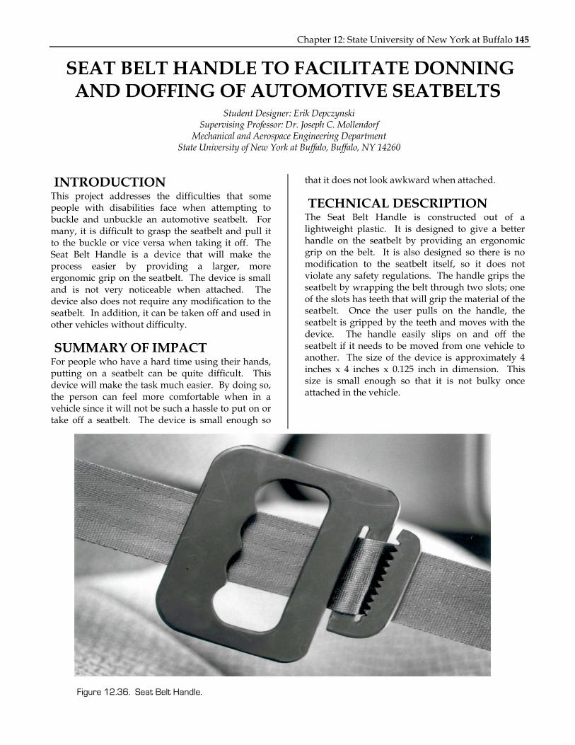
TECHNICAL DESCRIPTION The Seat Belt Handle is constructed out of a lightweight plastic. It is designed to give a better handle on the seatbelt by providing an ergonomic grip on the belt. It is also designed so there is no modification to the seatbelt itself, so it does not violate any safety regulations. The handle grips the seatbelt by wrapping the belt through two slots; one of the slots has teeth that will grip the material of the seatbelt. Once the user pulls on the handle, the seatbelt is gripped by the teeth and moves with the device. The handle easily slips on and off the seatbelt if it needs to be moved from one vehicle to another. The size of the device is approximately 4 inches x 4 inches x 0.125 inch in dimension. This size is small enough so that it is not bulky once attached in the vehicle.
Figure 12.36. Seat Belt Handle.

146 NSF 2002 Engineering Senior Design Projects to Aid Persons with Disabilities