chapter 12 hazard analysis and risk assessment …€¦ · table 12-2: summary of asme b31.8 land...
TRANSCRIPT

Chapter 12 Hazard Analysis and Risk Assessment (Unplanned Events)


SCP Expansion Project, Georgia
Environmental and Social Impact Assessment Final
Hazard Analysis and Risk Assessment i March 2013
TABLE OF CONTENTS
12 HAZARD ANALYSIS AND RISK ASSESSMENT.......................................12-1 12.1 Introduction .............................................................................................12-1
12.1.1 Principles of Hazard and Risk Management .............................................. 12-2 12.1.2 Risk Assessment ........................................................................................ 12-2
12.2 Pipeline Design and Risk ........................................................................12-5 12.2.1 Pipeline Design Codes and Standards....................................................... 12-5 12.2.2 Safety Risk Results and Discussion........................................................... 12-9 12.2.3 Separation Distances ............................................................................... 12-10 12.2.4 Pipeline Protection Zones ........................................................................ 12-12 12.2.5 Fault Crossing Mitigations ........................................................................ 12-12
12.3 Facility Design and Risk........................................................................12-13 12.3.1 Facility Codes and Standards .................................................................. 12-13 12.3.2 Facility Risk Assessment.......................................................................... 12-13 12.3.3 Facility Protection Zones .......................................................................... 12-16
12.4 Impact Significance Assessment ..........................................................12-16 12.4.1 Potential Impacts of Unplanned Events: Construction ............................. 12-16 12.4.2 Potential Impacts of Unplanned Events: Pipeline Operation .................... 12-17 12.4.3 Potential Impacts of Unplanned Events – Facility operation .................... 12-18
12.5 Risk Assessment ..................................................................................12-18 12.6 Mitigation Measures..............................................................................12-20
12.6.1 Mitigation Measures Incorporated into the Design ................................... 12-20 12.6.2 Operational Controls ................................................................................ 12-21 12.6.3 Emergency Response Capability ............................................................. 12-22
12.7 Residual Risk ........................................................................................12-24 Tables Table 12-1: Line Pipe Installation, Operational and Coating Data......................... 12-5 Table 12-2: Summary of ASME B31.8 Land Use/Location Class Criteria for Design Factor ....................................................................................................................12-6 Table 12-3: Location Classes, Design Factors and Wall Thicknesses ..................12-6 Table 12-4: ASME31.8 Location Classes on the SCPX Pipeline in Georgia ......... 12-7 Table 12-5: Location and Proximity to SCPX of Crossovers, Settlements and AGIs..............................................................................................................................12-8 Table 12-6: Thermal Radiation Contours for Buried High-Pressure Pipelines....... 12-9 Table 12-7: Restriction and Consultation Zones – Pipeline................................. 12-12 Table 12-8: Impact and Probability Assessment for Unplanned Events.............. 12-19 Figures Figure 12-1: Causes of Serious Gas Transmission Incidents................................12-1 Figure 12-2: Risk Assessment Methodology .........................................................12-4 Figure 12-3: SCPX Separation from BTC Pipeline..............................................12-11 Figure 12-4: CSG2 Gas Dispersion, LFL for 50mm Hole .................................... 12-14 Figure 12-5: CSG2 Heat Radiation from a Gas Jet Fire ......................................12-15

SCP Expansion Project, Georgia
Environmental and Social Impact Assessment Final
Hazard Analysis and Risk Assessment ii March 2013
Figure 12-6: CSG2 Explosive Overpressure from Accidental Gas Release ........ 12-16 Figure 12-7: Residual Risk Significance Matrix ................................................... 12-19

SCP Expansion Project, Georgia
Environmental and Social Impact Assessment Final
Hazard Analysis and Risk Assessment 12-1 March 2013
12 HAZARD ANALYSIS AND RISK ASSESSMENT
12.1 Introduction
This chapter summarises the hazard analysis and risk assessment studies carried out for the SCPX Project concept that was described in Chapter 5. It describes and assesses unplanned events that could potentially cause risks to public safety and harm to the environment. It also outlines the proposed mitigation measures and the strategy proposed that aims to manage the risks potentially associated with the Project. The European Commission Directorate-General Environment1 has reported that there is a decreasing incident rate for both gas and oil pipelines in Europe. Years of experience of operating pipelines, including the existing SCP, BTC and WREP pipelines in Georgia, has also contributed to the creation of potential improvements for the mitigation and management of the associated risks. Because the SCPX Project will transport natural gas, the most serious type of unplanned event is considered a release of gas that ignites and causes a fire or explosion. Statistics compiled by the US Department of Transportation’s Office of Pipeline Safety suggest that the most frequent causes of gas pipeline release scenarios are likely to be excavation damage followed by materials failure (see Figure 12-1).
Figure 12-1: Causes of Serious Gas Transmission Incidents
In addition to excavation damage and material failure, the SCPX Project has also taken the following causes of gas releases into consideration:
SCPX construction close to live SCP, BTC and WREP pipelines and tie-ins into the live SCP pipelines and plant at CSG1, CSG2 and PRMS
Pipeline rupture as a result of natural hazards
External interference (including illegal hot tapping, or damage resulting from terrorism or war).
1 http://www.egig.eu (accessed 4 April 2012)

SCP Expansion Project, Georgia
Environmental and Social Impact Assessment Final
Hazard Analysis and Risk Assessment 12-2 March 2013
12.1.1 Principles of Hazard and Risk Management Risk is an expression of the likelihood that an event will occur and the magnitude of the potential consequences if it does occur. Risk can therefore be lowered by reducing the likelihood of occurrence and/or the severity of consequences. Preventing any initial failure occurring is arguably therefore the most effective way to reduce the risk of causing harm to people or to the environment. Risk assessment for gas pipelines and facilities focuses primarily on the estimation of risk to the public safety. The development of comprehensive, internationally recognised codes and standards based on good engineering practice and operational experience has allowed for the design of inherently safer gas pipelines and facilities that are designed to include safety elements that are intended to reduce the potential for major accidents to occur. The SCPX Project design strategy has benefited from the experience gained from the design of the BTC and SCP pipelines and lessons learned from the construction, commissioning, operation and maintenance of these pipelines and facilities. The industry applies hazard and risk management not just to the design process, but also during construction and operation of the pipeline and facilities. The industry accepted hazard and risk management approach seeks to demonstrate that safety risks have been reduced to a level considered as low as is reasonably practicable in the applicable circumstances. The use of the term ‘as low as is reasonably practical’ refers to its application within a hazard and risk management approach and does not refer to its use as a legal concept or standard.
12.1.2 Risk Assessment Risk assessment is both a design tool and a valuable tool for ranking potential risks during the lifetime of a gas pipeline or facility, prioritising operational efforts to reduce the likelihood of leakage, and guiding emergency planning. It can be used to assist decision-making on future land use in the vicinity of the pipelines and facility on the basis of pipeline safety. A risk assessment has been undertaken to demonstrate the potential risk to the public from installation of the 56”-diameter SCPX pipeline and facilities, using a risk assessment methodology that draws extensively on published sources (e.g. Morgan and Hill, 1997; Morgan, 1995, 1989; Corder, 1995; Hill and Catmur, 1995; Carter, 1991) and the following documents:
John Brown Hydrocarbons Pipeline Risk Assessment
Azerbaijan Strategic Performance Unit - Caspian Region (BTC/SCP) Pipeline Zones document.
The main steps in the risk assessment process are shown in Figure 12-2 and are briefly discussed below.
1. Identify potential failure causes The objective of this step is to identify potential failure causes for a natural gas pipeline system or facility.
2. Estimate failure frequencies The objective of this step is to estimate the potential frequency of system failure for each failure cause. Historical accident data are used as a basis to estimate the generic failure frequencies that are adjusted for the specific features of the proposed system. For the SCP pipeline, failure frequencies have been based on those reported by European Gas Pipeline Incident Data Group (EGIG) website and have been compared with other sources of data (e.g. US Department of Transport (DoT) Gas Transmission Pipelines, and the UK Onshore Pipeline Operators Association (UKOPA)) to provide a cautious best estimate of the pipeline failure frequencies. The UKOPA data demonstrates much lower frequencies of failure,

SCP Expansion Project, Georgia
Environmental and Social Impact Assessment Final
Hazard Analysis and Risk Assessment 12-3 March 2013
especially of rupture, than EGIG. This likely reflects the fact that pipelines in the UK are typically newer and use more modern design codes than the ones reported by EGIG and US data. However, EGIG data has been conservatively adopted for the base-case generic frequencies because it is a much larger data source and covers a wider range of terrain. The gas industry failure frequency assessment model FFREQ was also used as input for the assessment of external interference and third-party damage.
3. Identify potential release modes The objective of this step is to identify the potential modes in which gas may be released into the atmosphere following a system failure. The release modes may be characterised in terms of the hole size caused by the failure. For instance, small holes would be leaks with relatively low gas release rates and limited consequence distance. At the other end of the spectrum would be a full-bore pipeline rupture with a higher release rate and the ability to disperse gas some distance.
4. Estimate release frequencies The objective of this step is to estimate the frequency of release in each mode. This step combines the failure frequencies (from Step 2) with the hole size distribution given a failure owing to a specified cause. Again, historical failure data has been used to estimate generic release frequencies and Project-specific data used to adjust these frequencies as appropriate. This has included taking account of the reduction in major rupture frequencies due to lower design factors, increased pipeline wall thickness and deeper burial. It also included increased failure frequencies in regions prone to geohazards.
5. Assess release consequences The objective of this step is to assess the severity of consequences of a release in each mode. The potential consequences of the different kinds of release were calculated using established software models. In considering the potential effects of a release, different possible scenarios have been considered, such as whether a release is ignited immediately or after some delay.
6. Calculate risk to the public The objective of this step is to estimate the risk of the proposed pipeline or facility to the public living in the vicinity. A conservative approach was taken to estimating the risk to an individual, by assuming a base case of a hypothetical individual being present at a given location 24 hours a day, 365 days a year (an unrealistic assumption, but it builds conservatism into the calculation). This risk is expressed as the individual risk of fatality per year at a given distance from the pipeline. Clearly the actual risk to a real person is considered likely to be much less than this, as no individual stays in the same location permanently. Nonetheless, it is a frequently used comparative tool for pipeline risk assessment. This risk calculation includes the previous steps discussed above and considers such factors as the likelihood of an ignition and whether the majority of releases will disperse into the atmosphere harmlessly without being ignited.

SCP Expansion Project, Georgia
Environmental and Social Impact Assessment Final
Hazard Analysis and Risk Assessment 12-4 March 2013
Figure 12-2: Risk Assessment Methodology
7. Assess the significance of the risk This step evaluates the significance of the estimated risk in light of well-established and published criteria of ‘acceptable’ risk (in a risk management context) for communities (see for example UK HSE, 2001), and common oil and gas industry practice for international operators.
8. Identify and evaluate additional risk prevention or risk mitigation measures as appropriate, and recalculate risks The objective of this step is to assess the benefits of additional risk prevention or risk mitigation measures if necessary with the aim of further managing and mitigating potential risks. Section 12.2 discusses the design codes and standards that apply to the 56”-diameter SCPX pipeline and the risk assessment studies that have been carried out for it. Section 12.3 discusses the design codes and standards that apply to the SCPX facilities and the risk assessment studies that have been carried out for them.

SCP Expansion Project, Georgia
Environmental and Social Impact Assessment Final
Hazard Analysis and Risk Assessment 12-5 March 2013
12.2 Pipeline Design and Risk
In Georgia, the SCPX pipeline generally follows the route of the existing BTC and SCP pipelines, which avoids existing development and local infrastructure. However, a number of communities are relatively close to the pipeline ROW. The proposed SCPX design has located the SCPX pipeline, block valve stations and pigging stations where they can share utilities with existing facilities, while allowing sufficient distance between them, and sufficient separation from the existing BTC and SCP pipelines and their AGIs to minimise the likelihood of escalation in an accidental event (see Section 12.2.3 and Section 12.3.2).
12.2.1 Pipeline Design Codes and Standards Table 12-1 presents design data for the 56"-diameter SCPX pipeline.
Table 12-1: Line Pipe Installation, Operational and Coating Data
Data Parameter Value
SCPX outer diameter 1 56”/1422.4mm
Yield stress 485MPa
Line pipe data
Manufacturing tolerance Nominal wall thickness +/-0.75mm
Design life 30 years
Design pressure 95.5 barg
Maximum operating temperature 60°C
Operational data
Minimum operating temperature -10°C
External three-layer polyethylene thickness 3mm
External three-layer polyethylene density 900kg/m3
Factory-applied concrete-coating density Applied for specific hazards at river crossings etc., for anti-buoyancy reasons or local protection
3500kg/m3
Coating data
Field-applied concrete-coating density 2400kg/m3
A combination of a three-layer polyethylene coating, field joint coating and an integrated cathodic protection system aim to protect the pipeline from the risk of external corrosion. It is weight coated with concrete where negative buoyancy is needed in wet areas. The 56"-diameter SCPX pipeline is being designed in accordance with the latest version of the long-established American Society of Mechanical Engineers (ASME) B31.8 code for ‘Gas Transportation and Distribution Piping Systems’. Other international standards including applicable American Petroleum Institute (API) standards have also been incorporated into the design. ASME B31.8 bases its approach to public safety on design factors specifying the use of different classes of pipe depending on land use and population density (see Table 12-2). It implicitly mitigates the key risk associated with gas pipelines by specifying design factors that are intended to reduce the likelihood of pipeline ruptures in populated areas. The design factor is the ratio between the actual operating stress of the pipeline and the yield stress of the material from which it is made, and is an indicator of how much stress the pipeline could endure before it starts to deform. Increasing the pipeline wall thickness gives a greater margin between operating stress and yield stress, and it is considered to provide increased protection against mechanical impacts (e.g. from excavating and agricultural machinery), which are historically a main cause of major pipeline failures. For most of its length, the SCPX pipeline has a minimum design factor of 0.72 (Location Class 1, Division 2).
SCP Expansion Project, Georgia
Environmental and Social Impact Assessment Final
Hazard Analysis and Risk Assessment 12-6 March 2013
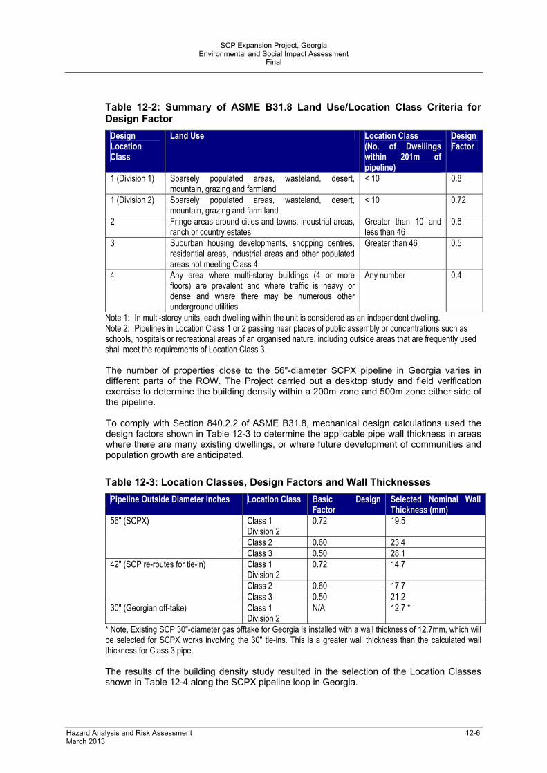
Table 12-2: Summary of ASME B31.8 Land Use/Location Class Criteria for Design Factor
Design Location Class
Land Use Location Class (No. of Dwellings within 201m of pipeline)
Design Factor
1 (Division 1) Sparsely populated areas, wasteland, desert, mountain, grazing and farmland
< 10 0.8
1 (Division 2) Sparsely populated areas, wasteland, desert, mountain, grazing and farm land
< 10 0.72
2 Fringe areas around cities and towns, industrial areas, ranch or country estates
Greater than 10 and less than 46
0.6
3 Suburban housing developments, shopping centres, residential areas, industrial areas and other populated areas not meeting Class 4
Greater than 46 0.5
4 Any area where multi-storey buildings (4 or more floors) are prevalent and where traffic is heavy or dense and where there may be numerous other underground utilities
Any number 0.4
Note 1: In multi-storey units, each dwelling within the unit is considered as an independent dwelling. Note 2: Pipelines in Location Class 1 or 2 passing near places of public assembly or concentrations such as schools, hospitals or recreational areas of an organised nature, including outside areas that are frequently used shall meet the requirements of Location Class 3. The number of properties close to the 56"-diameter SCPX pipeline in Georgia varies in different parts of the ROW. The Project carried out a desktop study and field verification exercise to determine the building density within a 200m zone and 500m zone either side of the pipeline. To comply with Section 840.2.2 of ASME B31.8, mechanical design calculations used the design factors shown in Table 12-3 to determine the applicable pipe wall thickness in areas where there are many existing dwellings, or where future development of communities and population growth are anticipated.
Table 12-3: Location Classes, Design Factors and Wall Thicknesses
Pipeline Outside Diameter Inches Location Class Basic Design Factor
Selected Nominal Wall Thickness (mm)
Class 1 Division 2
0.72 19.5
Class 2 0.60 23.4
56" (SCPX)
Class 3 0.50 28.1 Class 1 Division 2
0.72 14.7
Class 2 0.60 17.7
42" (SCP re-routes for tie-in)
Class 3 0.50 21.2 30" (Georgian off-take) Class 1
Division 2 N/A 12.7 *
* Note, Existing SCP 30"-diameter gas offtake for Georgia is installed with a wall thickness of 12.7mm, which will be selected for SCPX works involving the 30" tie-ins. This is a greater wall thickness than the calculated wall thickness for Class 3 pipe. The results of the building density study resulted in the selection of the Location Classes shown in Table 12-4 along the SCPX pipeline loop in Georgia.

SCP Expansion Project, Georgia
Environmental and Social Impact Assessment Final
Hazard Analysis and Risk Assessment 12-7 March 2013
Table 12-4: ASME31.8 Location Classes on the SCPX Pipeline in Georgia
Georgia Section SCP KP
ASME 31.8 Location Class Comments on Building Proximity
KP0 to KP23 Class 1 < 10 buildings within 200m of the pipeline
KP22 to KP43 Class 3
KP38–40 >46 buildings within 200m Class increased within KP22–39 and 41–43 to account for anticipated housing development
KP43–56 Class 1 < 10 buildings within 200m of the pipeline
As shown in Table 12-4, KP39–KP41 is the only location where the number of dwellings within 200m exceeds the ASME B31.8 criteria for Class 1 design factor. A design factor of 0.5 has been allowed, and heavy wall pipe will be used in KP39–41 where a number of dwellings are less than 200m from the pipeline (D12-01). A design factor of 0.5 has been allowed and heavy wall pipe will be used within KP22–KP43 around Rustavi to allow for future development and population expansion (D12-02). Wherever practicable the SCPX pipeline route has avoided populated or sensitive areas, and where it passes through areas of limited population, the wall thickness has been increased in accordance with ASME B31.8. In certain areas, the conservative engineering approach applied to SCPX pipeline design has gone beyond the strict requirements of the Code, resulting in:
Increased wall thickness with a design factor of 0.6 will be applied at major road, railway and river crossings and where the pipeline passes seismic faults to meet the requirements of API RP 1102 (D5-034)
increased depth of cover at crossings: road crossings will generally be installed with 2.0m cover; rail crossings have at least 3.0m cover and unpaved roads will have at least 1.5m cover (D11-02). Concrete slabs will be installed at open-cut road crossings to protect SCPX from future road construction activities and excavations along roads or the verges (D11-03)
Each major river crossing (i.e. the Mtkvari and the Algeti) will have a site-specific design specifying the minimum depth of cover, which will be set to account for the maximum flow rates (1:200 year storm event), sediment movement patterns, anticipated changes to the river bed contour and the predicted extent of lateral erosion (D12-06).
Table 12-5 shows where the SCPX pipeline will cross over major roads, railways, rivers and canals, and where it will be close to AGIs and facilities in which operational or security personnel may be employed.

SCP Expansion Project, Georgia
Environmental and Social Impact Assessment Final
Hazard Analysis and Risk Assessment 12-8 March 2013
Table 12-5: Location and Proximity to SCPX of Crossovers, Settlements and AGIs
SCPX KP
Crossing AGI & Distance Settlements and Distance
Notes
3.4 Asphalt road
2.6 SCP, BTC SCPX on South side of WREP, SCP & BTC from here
4
Pump station PSG1 (BTC), relocated Area 72 (SCP) to CSG1 (SCPX and SCP). Provision of receivers and launchers. End of 56" SCPX loop1 and start of loop 2 pipelines
Pipelines terminate and start at new station MX71 SCPX and SCP to the west of PSG1
SCPX and SCP pipelines approach BTC pumping station from the south-east re-routed west of pumping station to new site CSG1. WREP passes east of facilities unchanged
9.3 Tarmac road
9.3 Block valve station GB01 (BTC) <50m
11 Canal Main irrigation canal, 3.8m deep
11.1 Asphalt road
13 Lemshveniera 1km South of SCPX
24 Akhali Samgori 250m South of SCPX
25.8 Tarmac road
26.7 Seismic fault Rustavi seismic fault
29.1 Asphalt road
29.6 Asphalt road
29.9 Railway
30 Aghtakla 50m–100m North of SCPX
30 River Kura River East 31 Rustavi 300m South of SCPX 32 Rustavi 900m North of SCPX
34.9 Asphalt road.
35.9 Asphalt road
36 Check valve station GC04 (BTC)
39.5 Krtsanisi 800m North of SCPX
40.3 Asphalt road
40.4 Zoovetis Dasakhleba 100m South of SCPX
43.3 Asphalt road
44.4 Railway

SCP Expansion Project, Georgia
Environmental and Social Impact Assessment Final
Hazard Analysis and Risk Assessment 12-9 March 2013
SCPX KP
Crossing AGI & Distance Settlements and Distance
Notes
52.5 SCP, BTC SCPX on south side of WREP, SCP and BTC from here
53 Railway Single track
53.6 Asphalt road
53.8 Block valve station GB01 (BTC) 100m
53.8 Block valve station GB05 (BTC) 100m
The potential for the pipeline to fail as a full bore rupture (FBR) and “unzip” owing to accidental damage, or to leak without a full bore rupture occurring, has been assessed. The results of this assessment indicate that, provided the pipeline wall thickness is greater than 19.1mm, and the design factor is less than 0.5, the probability of an FBR occurring is very low. The risk of FBR is considered as low as reasonably practicable in risk assessment terms. The pipeline is more likely to fail by leaking without a rupture occurring.
12.2.2 Safety Risk Results and Discussion Consequence modelling techniques (PHAST and BP Cirrus) were used to predict the distance to heat radiation contours of the ignition of gas released from a 140mm-diameter hole in the buried 56”-diameter SCPX and 42”-diameter SCP pipelines. This is representative of a leak-before-rupture scenario and was used to ascertain its potential impact on dwellings, as required by ASME 31.8. Table 12-6 presents the distance to thermal radiation contours of 6.3kW/m2, 12.5kW/m2 and 35kW/m2 from an ignited gas jet fire resulting from a 140mm-diameter leak.
Table 12-6: Thermal Radiation Contours for Buried High-Pressure Pipelines
Radiation Contours (either side of pipeline, m)
Diameter Leak Size (mm) Flame Length (m)
35kW/m2 12.5kW/m2 6.3kW/m2 56"SCPX pipeline 140 96 87 140 182 42" SCP existing pipeline
140 77 66 104 139
The modelling concluded that along its whole length in Georgia, the SCPX pipeline is a Class 1, Division 2 pipeline and should have a design factor of 0.72 and a nominal wall thickness of 19.5mm. With this wall thickness, the pipeline is considered far less likely to rupture. A 140mm-diameter leak hole would be expected to reach a distance of approximately 180m from the pipeline before the thermal radiation reduced to a level at which personnel could escape (6.3kW/m2). However, where the ROW passes close proximity to communities (e.g. at Krtsanisi, Kumisi Dachas and in the Gardabani district) using a design factor of 0.5 and increased pipeline wall thickness further reduces the probability of 'leak before rupture' occurring. For SCP and BTC, risk transects were calculated for the three ASME B31.8 location classes (defined in Table 12-2) and risks were found to be within the well-established and published criteria of ‘acceptable’ risk (in a risk management context) for communities. For the 56”-diameter SCPX pipeline, the increased wall thickness has a significant positive impact with regard to reducing the risk of failure frequency. Considering the BTC, SCP, WREP and SCPX pipelines together slightly increases the overall risk levels, but even with the introduction of SCPX pipeline the risk levels are

SCP Expansion Project, Georgia
Environmental and Social Impact Assessment Final
Hazard Analysis and Risk Assessment 12-10 March 2013
considered to remain extremely low. As long as adequate pipeline separation is implemented or additional protection measures included where the separation distance is reduced, an accidental event is considered unlikely to escalate to an adjacent pipeline in the ROW.
12.2.3 Separation Distances
Pipeline When routed on the right hand side of the ROW corridor, the 56”-diameter pipeline SCPX is adjacent to the SCP gas pipeline; when routed on the left hand side, it is adjacent to the BTC oil pipeline. Modelling studies comparing the results from two Pipeline Research Council International (PRCI) models, a BP model and industry data from incidents on similar pipeline were used to determine the minimum recommended distance between the SCPX pipeline and one of the existing pipelines. The models simulated a full-bore rupture across the entire diameter of the SCPX pipeline operating at 90 barg (the worst-case event and one which is considered unlikely owing to the design mitigations discussed above Section 12.2.1). The modelling provided an estimate as to whether the crater from an explosion would expose the adjacent pipeline, thereby potentially causing a loss of integrity, and whether heat radiation would be likely to affect the adjacent exposed pipeline. The largest crater radius from the modelling results was 18.4m produced by the BP model, which presents a worst-case scenario (i.e. a larger crater radius than the PRCI models and actual historical data). A general minimum separation distance of 20m is applied between SCPX and SCP/BTC. At crossings, additional control of work measures will be applied (D11-04). When SCPX is adjacent to BTC to allow room for setting out and constructing the 56” pipeline, the actual separation distance will generally be in the region of 36m (see Figure 12-3). There are currently expected to be four points in Georgia where the SCPX pipeline crosses under the existing BTC and SCP pipelines. Where the SCPX pipeline crosses buried services or pipelines, trenchless or open cut crossing methods will be adopted. A typical vertical separation between the SCPX pipeline and the existing service or pipeline will be 1500mm where trenchless techniques are used, and 900mm where open cut techniques are used (D5-010). Construction of crossings of the existing BTC and SCP pipelines will be controlled under the existing pipeline operations permit to work system and the activity will be subject to a specific risk assessment undertaken by both the construction contractor and BTC and SCP operations team (D5-011). During the operational phase the pipelines, including crossings will be subject to the operational monitoring as defined in Section 12.6.2.

SCP Expansion Project, Georgia
Environmental and Social Impact Assessment Final
Hazard Analysis and Risk Assessment 12-11 March 2013
Figure 12-3: SCPX Separation from BTC Pipeline
Block valve Block valves allow sections of pipelines to be isolated from the rest of the pipeline to carry out maintenance or in response to an emergency. The distance between one block valve and the next on the SCP pipeline was determined using a risk-based approach consistent with the ASME B31.8 standard (2007) that considered:
The amount of gas expected to be released for maintenance blowdowns, leaks or ruptures
The time expected to be needed to blowdown an isolated section of the pipeline The potential impact in the area of the gas release.
As the maximum allowable operating pressure of the SCPX system (90 barg) will be the same as for the SCP system, an SCPX pipeline risk assessment concluded that it would be

SCP Expansion Project, Georgia
Environmental and Social Impact Assessment Final
Hazard Analysis and Risk Assessment 12-12 March 2013
appropriate for the 56”-diameter pipeline to be located with approximately the same spacing distances as the existing SCP block valve stations. In Georgia, there will therefore be a block valve within CSG1, a stand-alone block valve at KP28 (adjacent to the existing SCP and BTC block valves) and an isolation valve acting as a third block valve in the pigging station at the end of the 56”-diameter pipeline (KP56). A risk analysis was undertaken to evaluate the potential for a major accident at the SCPX block valve affecting a block valve on the SCP or BTC pipelines and to determine the appropriate separation distance of the pipelines at block valve stations. Modelling of a full bore rupture of the SCPX (i.e. the worst case) using the same methodology described above (Section 12.2.3) estimated that with 28m separation distance between pipelines at the block valves, the edge of the crater would not affect the foundation of the firewall at the block valve on the other pipeline. Heat radiation from the jet fire caused by ignition of gas released from a full bore rupture of the 56”-diameter pipeline at a block valve is not expected to impact either pipeline, because it is protected by burial to a minimum depth of 1m. The heat radiation could damage aboveground elements of the other block valve, although the frequency of this type of event is very low and well below accepted industry standards. Based on the above evaluation, it was determined that there needs to be a minimum of 3m separation distance between the edge of the largest crater that could be caused by an explosion at the SCPX block valve and the firewall at the SCP block valve. At the block valve location (KP28) the separation distance between the 56” SCPX pipeline and the 42” SCP pipeline will be no less than 28m (D11-05).
12.2.4 Pipeline Protection Zones The zones in which construction activities are prohibited or restricted and the zones in which developers must consult with the operators of pipeline prior to construction activities are presented in Table 12-7. These pipeline protection zones meet international design standards and engineering good practice, as required by the HGA. The same zones apply to the BTC and SCP pipelines.
Table 12-7: Restriction and Consultation Zones – Pipeline
Zones Extent Requirement Zone 1 4 metres either side of pipeline Building construction, tree planting, deep
ploughing and use of explosives is prohibited
Restriction zones
Zone 2 15 metres either side of pipeline Construction of habitable buildings is prohibited
Zone 3-1 385 metres either side of pipeline All housing developments are subject to consultation with the pipeline operator
Consultation zones
Zone 3-2 Between 385 metres and 500 metres either side of pipeline
Major developments (hospitals, schools and large housing developments) are subject to consultation with the pipeline operator
Any planned developments within Pipeline Protection Zone 3 will be subject to consultation with the project, as required by national legislation.
12.2.5 Fault Crossing Mitigations The pipeline follows the SCP/BTC pipeline corridor, which was designed to take account of geological fault lines in the Rustavi area. The SCPX Project reviewed the active fault crossings for the existing SCP pipeline to confirm the results of the fault identification process, and the methodology for determining the potential rupture zones and characterisation of the faults. The review confirmed that the SCPX pipeline will only cross

SCP Expansion Project, Georgia
Environmental and Social Impact Assessment Final
Hazard Analysis and Risk Assessment 12-13 March 2013
one potentially active fault in Georgia, known as the Rustavi fault at KP26.4. The section of the pipeline trench that crosses the Rustavi fault will be excavated in a trapezoidal shape, double lined with geotextile membrane and filled with non-cohesive, graded aggregate (D5-006), which will allow free and unrestricted movement of the pipe with the ground surface during a potential seismic event and avoid causing a rupture.
12.3 Facility Design and Risk
The Project proposes to construct two compressor stations (CSG1 at KP03 and CSG2 at KP142) in Georgia and to extend the PRMS at KP247 on the Georgia/Turkey border. The proposed SCPX design has located CSG1 and the PRMS where they can share utilities with existing facilities (BTC’s PSG1 and SCP Area 80). Selection of facility locations took account of:
Process, hydraulic and operational constraints
The potential effects on the local environment and project affected communities at specific locations
The likely impact on the existing pipeline export facilities and avoidance of personnel working on 'live' equipment
The likely ease of construction at the selected site
The potential hazards of material and personnel transport logistics to the site
Likely measures necessary for reduction of gas inventory and the safe isolation and disposal of the hazardous materials in the event of an unplanned event involving the release of process gas.
12.3.1 Facility Codes and Standards Piping systems at the facilities are designed to ASME B31-3 ‘Code for Pressure Piping’ Pipeline systems at the facilities are designed to ASME B31-8 (D12-05) and mostly use a design factor of 0.3 and greater pipe wall thickness than the 56”- and 42”-diameter pipelines. This is considered likely to greatly reduce the likelihood of an accidental full bore rupture of the pipework. Accordingly, the worst-case accident event used to design the facility layout was a 50mm hole in the high-pressure gas systems. Pressure vessels at the facilities are designed to ASME BPVC Section VIII ‘Rules for Construction of Pressure Vessels’ Division 1. The seismic design criteria specified within American Society of Civil Engineers ASCE 7-10: Minimum Design Loads for Buildings and other structures has been applied to the Project. The document provides guidance on the structural design parameters that are used under different predicted seismic load conditions. Depending on the seismic conditions and intensity of the site, which have been identified for each facility as part of a desktop study, design parameters for buildings, foundations, pipework and structural steel will be prepared in accordance with the ASCE standard. The standard defines different structure classes with specific design parameters for structures, buildings and foundations. These structure classes depend on a variety of factors including seismic conditions, soil type and structure lifespan. Each facility will be designed based on site-specific parameters and structure classification.
12.3.2 Facility Risk Assessment The focus of facility risk assessment has been to aim to verify that major gas release from process-related systems and equipment would not escalate to adjacent systems or beyond the site perimeter fence. The consequences of accidental release scenarios at each facility were modelled to estimate gas dispersion, heat radiation and explosion overpressures in the

SCP Expansion Project, Georgia
Environmental and Social Impact Assessment Final
Hazard Analysis and Risk Assessment 12-14 March 2013
event that released gas ignites. Examples of the modelling results for CSG2 are given in the following sections.
Gas dispersion Figure 12-4 shows the extent of the lower flammability limit (LFL) as a result of an accidental release from a 50mm hole in the high-pressure gas systems at CSG2. The LFL does not extend beyond the boundary fence from the site indicating that flammable gas would not reach areas that can be accessed by the public. Each facility can be depressurised to a safe location from maximum operating pressure to 7 barg in 15 minutes via a cold vent stack. The plant is sited such that the likelihood is that the prevailing wind would disperse flammable releases away from known ignition sources such as the gas turbine exhausts and ventilation inlets.
Figure 12-4: CSG2 Gas Dispersion, LFL for 50mm Hole
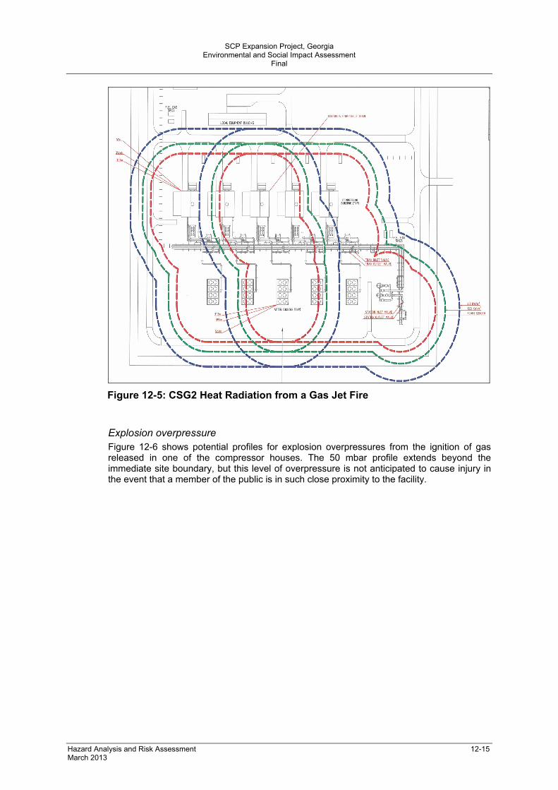
Thermal radiation Figure 12-5 shows heat radiation profiles from the ignition of an initial gas release and a gas jet fire while the systems are under pressure. The radiation profile for 6.3kW/m2, which represents a level of thermal radiation from which it is possible for personnel to escape, would extend slightly beyond the perimeter fence. The initiation of emergency blowdown to depressurise the systems is intended to rapidly reduce the area that experiences a radiation level of 6.3kW/m2. A zone around the cold vent will be fenced to exclude the public from areas where thermal radiation levels are considered likely to harm them in the event that the vented gas ignites (D12-07).
SCP Expansion Project, Georgia
Environmental and Social Impact Assessment Final
Hazard Analysis and Risk Assessment 12-15 March 2013
Figure 12-5: CSG2 Heat Radiation from a Gas Jet Fire
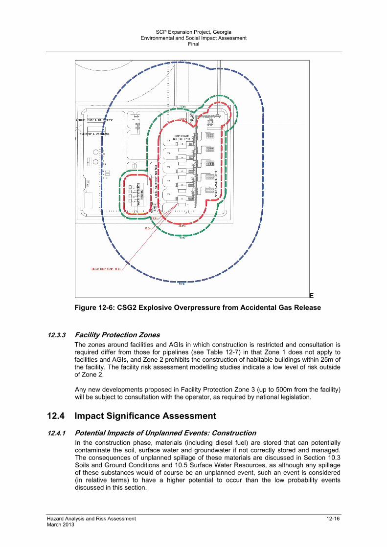
Explosion overpressure Figure 12-6 shows potential profiles for explosion overpressures from the ignition of gas released in one of the compressor houses. The 50 mbar profile extends beyond the immediate site boundary, but this level of overpressure is not anticipated to cause injury in the event that a member of the public is in such close proximity to the facility.
SCP Expansion Project, Georgia
Environmental and Social Impact Assessment Final
Hazard Analysis and Risk Assessment 12-16 March 2013
E
Figure 12-6: CSG2 Explosive Overpressure from Accidental Gas Release
12.3.3 Facility Protection Zones The zones around facilities and AGIs in which construction is restricted and consultation is required differ from those for pipelines (see Table 12-7) in that Zone 1 does not apply to facilities and AGIs, and Zone 2 prohibits the construction of habitable buildings within 25m of the facility. The facility risk assessment modelling studies indicate a low level of risk outside of Zone 2. Any new developments proposed in Facility Protection Zone 3 (up to 500m from the facility) will be subject to consultation with the operator, as required by national legislation.
12.4 Impact Significance Assessment
12.4.1 Potential Impacts of Unplanned Events: Construction In the construction phase, materials (including diesel fuel) are stored that can potentially contaminate the soil, surface water and groundwater if not correctly stored and managed. The consequences of unplanned spillage of these materials are discussed in Section 10.3 Soils and Ground Conditions and 10.5 Surface Water Resources, as although any spillage of these substances would of course be an unplanned event, such an event is considered (in relative terms) to have a higher potential to occur than the low probability events discussed in this section.

SCP Expansion Project, Georgia
Environmental and Social Impact Assessment Final
Hazard Analysis and Risk Assessment 12-17 March 2013
Unplanned events during SCPX Project construction could affect community safety and security. Accidents at construction sites and Project-related road traffic accidents have been assessed in Section 10.12 (Community Health and Safety).
12.4.2 Potential Impacts of Unplanned Events: Pipeline Operation
Pipeline failure In historic cases when pipeline integrity has failed and leaking gas has found a source of ignition and exploded, the following potential outcomes may occur:
Crater formation close to the source of the leak
A fireball
An area of earth scorching around the crater
A wider area in which vegetation, trees, crops and buildings could potentially be damaged by fire
An even wider area in which noise from the explosion could potentially cause damage or disturbance to residents
Release of greenhouse gases.
Where such an explosion occurs, the crater would be expected to cause an environmental impact of short duration. The scorched earth would be anticipated to have no ground cover, facilitating a greater risk of erosion. In respect of the SCPX pipeline, most of the 56”-diameter pipeline route passes through arable farmland, grazing pasture, grassland and scrub vegetation. In the event of an explosion, this landscape could potentially allow a fire to spread, at least until the emergency response plan is activated and action is taken to contain the fire. The 56”-diameter pipeline route only passes through small fragments of woodland so it is considered unlikely that a forest fire could be started by a pipeline failure and explosion. Evidence exists of gas explosions being sufficiently powerful to cause superficial damage to buildings up to a distance of one kilometre from the source (MARS 8/1987). It is probable that the resulting noise immediately following an explosion would cause alarm to nearby residents in surrounding communities. Noise levels are expected to be reduced as the inventory of gas is released to the atmosphere and as the pipeline section is depressurised. Isolation of the pipeline section where the rupture occurs is anticipated to limit the duration of an incident to a few minutes. The maximum distance between block valves on the SCPX pipeline loop in Georgia will be 25km; therefore, in the unlikely event of a full bore rupture, gas release would be approximately 2000 tonnes of pipeline gas. If the released gas does not ignite, the release would represent 50,000 tonnes of CO2eq. If the released gas ignites, emissions would be approximately 6000 tonnes of CO2.
River crossing exposure A buried pipeline can be exposed at a river crossing due to the vertical lowering of the riverbed and/or lateral retreat of either of the riverbanks. Degradation is a general lowering of the channel bed elevation through time that may cause exposure of the pipeline. Bank retreat or lateral scour is movement of the stream bank into the floodplain expected due to the evolution of the channel in dynamic equilibrium or unexpected bank-line shifting in response to disturbance of the fluvial system. Exposure of the pipeline leaves it vulnerable to potential interference and the potential for failure as described above.

SCP Expansion Project, Georgia
Environmental and Social Impact Assessment Final
Hazard Analysis and Risk Assessment 12-18 March 2013
12.4.3 Potential Impacts of Unplanned Events – Facility operation In the scenario modelled for the worst-case gas release from facilities, the released gas may ignite and form a jet fire. In these circumstances it is anticipated that the proposed design is such that the potential fire would be contained within the site and that blowdown would reduce the length of the jet fire and its duration. The emergency depressurisation systems included in the design of each facility are intended to allow the operator to initiate a manual operation to vent the whole facility or isolated sections of the facility (e.g. a single compressor train) to 7 barg in a controlled manner within an estimated 15 minutes. The operator may then choose to continue venting to reach atmospheric pressure. This would take approximately another 25 minutes. Total facility blowdown (the worst case) is anticipated to allow venting of the entire inventory of gas within the compressor station to atmosphere. Such venting would cause noise, and the gas vented is a greenhouse gas.
Noise In the event of emergency venting, noise levels generated would be expected to be high and likely to be clearly audible at receptors surrounding the facilities. There is therefore a risk that such activity may give rise to short-term disturbance. At the SCPX facilities, simulations indicate that blowdown could last for up to 40 minutes, with the highest noise levels anticipated to be at the start of the venting process when gas flows are at their greatest. At receptors surrounding the facilities, LAmax (assumed to be approximate to the sound level C-weighted peak as per the criteria in Chapter 3) and weekly noise exposure levels (LEP, w) from venting have been predicted as follows:
CSG1 – N1: LAmax of 109 dB(A) and LEP, w of 80 dB(A) CSG2 – N3: LAmax of 91 dB(A) and LEP, w of 62 dB(A) PRMS – N1: LAmax of 89 dB(A) and LEP, w of 62 dB(A)
During emergency venting, it is predicted that the closest receptor (CSG1-N1) would experience noise up to the lower exposure action level given in the UK Noise and Work Regulations 2005 (which have been considered for benchmarking purposes only). At the lower exposure action level employers are required to educate employees on the risk of damage to hearing from high noise levels, employer obligations and to provide hearing protection (although there is no obligation to wear hearing protection at this level). Fitting silencers to the emergency vents has been considered as a potential mitigation measure. However, this has been disregarded as counter-productive because it would likely impede gas flow, increase the time needed to depressurise the facility and make the facility less inherently safe. Noise levels are expected to be reduced as the inventory of gas is released to the atmosphere and until the facility or section is depressurised.
Greenhouse gas emissions Emergency blowdown of the internal volume of the inlet and outlet manifolds and all four compressors at CSG1 on one occasion would vent an estimated 1897 tonnes CO2eq and at CSG2 up to approximately 1483 tonnes CO2eq. Blowdown of the internal volumes of the inlet and outlet manifolds and gas heaters at the PRMS would vent approximately 835 tonnes CO2eq.
12.5 Risk Assessment
Table 12-8 provides an assessment of the potential risks associated with unplanned events. The potential impact significance and potential event probability considers the potential impact and probability of an unplanned event if no mitigation had been incorporated into the project design or operating procedures.

SCP Expansion Project, Georgia
Environmental and Social Impact Assessment Final
Hazard Analysis and Risk Assessment 12-19 March 2013
The residual impact significance and probability takes account of the design measures that aim to minimise the probability and consequences of an unplanned event and the proposed operational control measures that are discussed in Section 12.6. This gives an overall assessment of the residual risk. The relevant tables from Chapter 3 have been used to assess the impacts. The impacts on community health and safety and the probability of the event occurring have been assessed using the Health Impact Assessment methodology outlined in Chapter 3. The residual risk has been evaluated based on the residual impact significance and event probability in accordance with the matrix presented in Figure 12-7.
Probability Impact Significance/Severity
1 2 3 4 5 6 7 8 Very High L H H H H H H H
High L L M M M H H H Medium L L L M M M M M
Low L L L L L M M M Very Low L L L L L L M M
Overall residual risk significance: H = High, M = Medium, L = Low
Figure 12-7: Residual Risk Significance Matrix
The results of the assessment are shown below (Table 12-8).
Table 12-8: Impact and Probability Assessment for Unplanned Events
Issue Potential Impacts
Potential Impact Significance
Potential Event Probability
Mitigations Residual Event Probability
Residual Risk
Event: Gas release from pipeline with explosion
A30 Community safety
Exposure to thermal radiation
Very High
Medium
A4 Loss of soil structure
Crater formation C3 Medium Low
A8 Visual intrusion Visible fireball B2 Low Low A3 Soil erosion Ground cover
removed where earth is scorched
B3 Low Low
A17 Loss of habitat Fire damage to vegetation
A2 Low Low
A32 Loss of agricultural land
Damage to crops B3 Low Low
A35 Damage to third party infrastructure
Damage to buildings
B2 Low Low
A25 Noise Noise disturbance from major incident
C5 High Medium
A31 Community health
Anxiety caused to residents in surrounding communities
Low
5 D11-02, D11-03 D11-04, D11-05 D12-01, D12-02, D12-03, D12-06, D5-001, D5-010 D5-011, D5-034, D5-095, D5-010
4-14,
D30-01, 32-07
OP121, OP20, OP123,
3
Low

SCP Expansion Project, Georgia
Environmental and Social Impact Assessment Final
Hazard Analysis and Risk Assessment 12-20 March 2013
Issue Potential Impacts
Potential Impact Significance
Potential Event Probability
Mitigations Residual Event Probability
Residual Risk
A23 Release of gases to atmosphere
Greenhouse gas emission
C4 Medium OP124, OP125, OP128, OP129 OP130, OP131, OP132, OP133, OP136, OP140, OP143, OP144
Low
Event: Gas release from facility with jet fire and facility blowdown
A30 Community safety
Exposure to thermal radiation
High Low
A25 Noise Noise disturbance from venting
C3 Medium Low
A23 Release of gases to atmosphere
Greenhouse gas emission
C4 Medium 5
D5-100, D12-05, D12-07 OP124, OP123, OP125, OP128, OP127 OP129, OP130
3
Low
12.6 Mitigation Measures
The mitigation measures for unplanned events are generally:
Design measures that limit both the impacts of the unplanned event and the probability that it will occur
Operational monitoring activities that make an unplanned event less likely to happen, but do not affect the impacts if it does happen, or
Operational response activities that limit the area impacted or the time for which the impact lasts.
12.6.1 Mitigation Measures Incorporated into the Design The following measures that have been incorporated into the SCPX Project design are intended to reduce the likelihood of an unplanned event:
A design factor of less than 0.5 has been allowed, and heavy wall pipe will be used in KP39–41 where a number of dwellings are less than 200m from the pipeline (D12-01)
A design factor of 0.5 has been allowed and heavy wall pipe will be used within KP22–KP43 around Rustavi to allow for future development and population expansion (D12-02)
An increased wall thickness with a design factor of 0.6 will be applied at major road, railway and river crossings and where the pipeline passes seismic faults to meet the requirements of API RP 1102 (D5-034)
Where normal agricultural activities will be carried out over the pipeline, it will be buried in a trench allowing a minimum depth of 1.0m between the top of the pipeline and the ground surface. On the pipeline loop, there will be increased depth of cover

SCP Expansion Project, Georgia
Environmental and Social Impact Assessment Final
Hazard Analysis and Risk Assessment 12-21 March 2013
at crossings; road crossings will generally be installed with 2.0m cover; rail crossings have at least 3.0m and unpaved roads have at least 1.5m cover (D11-02).
Each major crossing (i.e. the Mtkvari and Algeti rivers) will be set to account for the maximum flow rates (1:200 year storm event), sediment movement patterns, anticipated changes to the river bed contour and the predicted extent of lateral erosion (D12-06)
Concrete slabs will be installed at open-cut road crossings to protect SCPX from future road construction activities and excavations along roads or the verges (D11-03)
Where it is considered that there is a higher risk of the pipeline being damaged or interfered with, or where other services are crossed and at track and road crossings, the pipeline will be covered by concrete slabs at open cut crossings (D30-01)
A general minimum separation distance of 20m is applied between SCPX and SCP/BTC. At crossings, additional control of work measures will be applied (D11-04)
At the block valve location (KP28) the separation distance between 56” SCPX pipeline and the 42” SCP pipeline will be no less than 28m (D11-05)
Where the SCPX pipeline crosses buried services or pipelines, trenchless or open cut crossing methods will be adopted. A typical vertical separation between the SCPX pipeline and the existing service or pipeline will be 1500mm where trenchless techniques are used and 900mm where open cut techniques are used (D5-010)
Construction of crossings of the existing BTC and SCP pipelines will be controlled under the existing pipeline operations permit to work system and the activity will be subject to a specific risk assessment undertaken by both the construction contractor and BTC and SCP operations team (D5-011)
The SCPX pipeline will be protected from corrosion by an impressed current cathodic protection system (D5-001)
Piping systems at the facilities are designed to ASME B31-3 ‘Code for Pressure Piping’. Pipeline systems at the facilities are designed to ASME B31-8 (D12-05)
A leak detection system is provided on the pipeline. Following detection of a leak, the block valves on either side of the leak will be remotely closed so that the volume of release will be limited by the distance between the two block valves. (D12-03)
Local vents will be installed that will release the compressor seal gas to the atmosphere at a safe location if the seal gas recovery system fails (D5-100)
A zone around the cold vent will be fenced to exclude the public from areas where thermal radiation levels are considered likely to harm them in the event that the vented gas ignites (D12-07).
12.6.2 Operational Controls The mitigation measures that apply to unplanned spillage of hazardous materials in the construction phase are discussed in Section 10.3.4. The SCPX Project will apply the risk management principle of reducing the impacts to levels that are considered as low as is reasonably practicable in a risk management context by implementing the following measures:
The pipeline and facilities will be operated within the intended design conditions (OP124). The 56”-diameter SCPX pipeline will have an electronic leak detection system that continuously monitors a number of pipeline parameters including pressure, flow-rate and temperature and can identify the source and size of leak (see Section 5.8.5)
The pipeline and facilities will be regularly inspected and maintained (OP123) (see Section 5.8.4)
In-line inspection pigging operations will be carried out on a regular basis to provide information on the line integrity (OP132)

SCP Expansion Project, Georgia
Environmental and Social Impact Assessment Final
Hazard Analysis and Risk Assessment 12-22 March 2013
Monitoring of areas of geotechnical instability and erosion potential will be continued during operations (OP136)
The entire pipeline will be walked or ridden periodically to provide assurance that no unauthorised activities are taking place that could damage or otherwise affect the integrity of the pipeline. Sensitive sections of the pipeline will be patrolled at the highest frequency (OP20) and the condition of marker posts, ground cover and road, rail, and river crossings will be recorded
When the 56”-diameter pipeline is operating, regular patrols of the pipeline by ROW horse patrols, vehicular patrols (using existing access tracks) and security patrols will lessen the risk of third-party interference (OP121). The patrols, landowners and residents in the vicinity of the pipeline will be able to report safety incidents
Local residents will be advised of activities that could threaten the integrity of the pipeline, such as the extraction of aggregate (OP140)
The project will consult with local government authorities, landowners and land users, including graziers, before restricting access to land and will establish the need for temporary fencing (32-01)
The watercourses on the SCPX pipeline will be incorporated into the existing programme of inspection and maintenance. This will include
o Right of way (ROW) patrols will monitor river crossings to provide assurance of the integrity of any river protection works and riverbanks. This will include a visual inspection for river bank erosion or changes to channel morphology (OP131)
o An expert assessment of burial depths, set back measurements and pipeline protection works will be carried out annually (depending on the river characteristics and crossing technique) and after flood events exceeding a 1:100-year return period (OP143)
o Depending on river crossing monitoring results, additional maintenance measures, as deemed necessary by the Project, such as civil protection works which are necessary to maintain adequate depth of cover and set back, will be implemented (OP144)
The Project will maintain liaison with all landowners along the pipeline route and with authorities and utilities companies to track proposals for third party building activities that could affect the pipeline (OP133)
Monitoring of areas of geotechnical instability and erosion potential will be continued during operations (OP136)
The relevant authorities will be informed in the case of planned or actual third-party development within the relevant pipeline and facility protection zones (OP125)
CSG1 and CSG2 will have local emergency shutdown (ESD) and safety systems (OP127). In the event of telecommunications failure, CSG1 and CSG2 will be able to run safely in ‘station control mode’ under local control
In the case of an unplanned event, any damage will be reinstated and compensated where appropriate (4-14).
12.6.3 Emergency Response Capability The existing SCP pipeline has a Government-approved emergency response plan (ERP), which will be updated to integrate the SCPX pipeline and the new facilities before they become operational (OP128). The emergency response philosophy for SCPX will therefore be similar to that currently applied to SCP. In accordance with Appendix 4 Clause 3.6 of the HGA, the revised ERP will be submitted to GOGC (representing the Georgian Government) (OP129). It will include:
Environmental mapping of habitats vulnerable to potential natural gas leaks or emissions in the entire SCP system
SCP Expansion Project, Georgia
Environmental and Social Impact Assessment Final
Hazard Analysis and Risk Assessment 12-23 March 2013
Situational scenarios for potential leaks, emissions, explosions, fires and responses, taking into consideration local circumstances
Plans for the provision of relevant emergency response equipment, materials and services
Plans for the deployment of relevant equipment
Plans for notifying the organisation required to handle natural gas leaks, emissions, explosions and fires about emergency response details
Plans for evacuation and for the care of any injured persons and the remediation, restoration or compensation for any damaged property, and the treatment and disposal of any resulting contaminated materials.
All personnel are required to understand their roles and responsibilities described in the ERP and undertake training and instruction as necessary to ensure that they are competent to carry out their roles and responsibilities. Regular drills, musters and training are detailed in the annual emergency response exercise programme that will be updated to include SCPX-specific training and emergency drills (OP130).
Priorities BP’s incident management system aims to make best use of the available facilities and resources to respond to an accidental release of gas, should one occur, in a prompt and effective manner so as to minimise its consequences. The ‘Georgia Operations Emergency Response Plan’ is based on BP’s ‘Crisis Management Framework’ document that prioritises crisis management and emergency response in the following order:
1. People: Employees, contractors, suppliers, customers and communities 2. Environment: Air, water, land, spillages and areas of sensitivity 3. Property: BP, JV, contractors, communities and third-party facilities 4. Business: Supply, production and reputation
This approach implements an emergency response philosophy that encompasses overreacting, assessment, response and subsequent de-escalation.
Overreact The BP ‘Crisis Management Framework’ document highlights the need to respond effectively to any emergency situation with the intention that it will be controlled as quickly and as efficiently as possible. The resources deployed can be increased or reduced by the On-Scene Commander and Operations Section Chief at any time, as the situation becomes more clearly defined.
Tiered response To assure a consistent and effective response to unplanned events, a tiered response is adopted. The provision of resources to combat an emergency is divided into three categories or tiers of equipment provision. This system is internationally recognised as the most pragmatic approach, avoiding excessive costs and seeking shared resources for large, infrequent events.
Tier 1 (minor events): defined as small local incidents requiring no outside intervention that can be dealt with on site by local staff without support from the incident management team (IMT)
Tier 2 (emergency events): larger incidents that require additional local (regional) resources and manpower. This level of response needs the IMT to mobilise additional Georgia Operations in-country manpower/resources
SCP Expansion Project, Georgia
Environmental and Social Impact Assessment Final
Hazard Analysis and Risk Assessment 12-24 March 2013
Tier 3 (crisis events): very large, possibly ongoing incidents that need additional resources from outside Georgia and Azerbaijan. Such events are considered likely to be very rare, but could possibly include (for example) a full-diameter pipe rupture.
12.7 Residual Risk
Historically, large-diameter gas transmission pipelines have experienced fewer major accidents than medium-diameter gas distribution pipelines that deliver gas to residential areas. The social impacts of major accidents at large-diameter gas transmission pipelines and facilities have been limited by routing the pipelines away from residential areas. Impacts of a major accident would be of high environmental and social significance with potentially high impacts on community safety and noise disturbance that occurs during major incidents. The probability of such events, however, is reduced considerably through the use of design and operational mitigation measures, thus reducing the overall risk. The Project design and the operational control measures proposed are intended to reduce the impacts and probability of a major accident to level of risk that are considered “tolerable” in a risk management context. As a risk management measure, the public will be excluded from the most hazardous areas, such as the pipeline AGIs, the facilities and the sterile areas surrounding vent stacks. Any risk to the on-site workforce is intended also to be mitigated and managed to levels that are considered to be as low as reasonably practicable in a risk management context, by (for example) employing applicable facility design, by implementing safe working practices and through training of relevant personnel. The overall assessment of residual risk is generally of low significance with a medium significance for the risks to community health and safety from unplanned events on the pipeline.