chapter 11a: motor sizing and selection 0908531...
TRANSCRIPT

Chapter 11a: Motor Sizing and Selection for Geared Hoisting Systems
0908531: Mechatronics System Design
Source URL: http://www.ju.edu.jo/sites/Academic/l.sharif/Material/Forms/AllItems.aspx Saylor URL: http://www.saylor.org/courses/me302 Attributed to: [Dr. Lutfi R. Al-Sharif] www.saylor.org Page 1 of 1
Chapter 11a Motor Sizing and Selection for Geared Hoisting Systems Dr. Lutfi R. Al-Sharif (Revision 1.0, 21/12/2007)
1. Introduction The rotational inertia calculations have been discussed in Chapter 6 earlier. All the calculations earlier have assumed no gearing between the motor and the load. The Chapter assumes that a speed reduction gearbox is used between the motor and the load, and revises the calculations carried out earlier to take this into consideration. It also allows the effect of the system efficiency in the calculations. 2. Effect of gearing When a gearbox is fitted between the motor and the drive, it has an effect on the torque, speed and inertia. In general, a gearbox is used to match the drive to the load. Most gearboxes are used as reduction gearbox (i.e., to reduce the rotational speed). Thus the speed will be reduced, and the torque will be increased. This is very useful in practice; the rotational speed of most motors is too high to directly drive the load, and the torque is too low. The gearbox matches the drive to the load. Before showing these relationships as equations, we shall introduce a convention. The motor shaft is sometimes referred to as the high speed shaft (HSS) and the load shaft is sometimes referred to as the low speed shaft (LSS).
3. Inertia of Translational Masses In the previous analysis we have not allowed for a gearbox. In this section, a gearbox is included in the analysis.
This Chapter will consider a motor with fitted with a flywheel driving a translational load through a gearbox. A sheave of diameter ds is used to drive the ropes as a traction drive.
In this section, we discuss the method of referring the translational masses, to the motor shaft. This is necessary in order to calculate the rotational acceleration at the motor shaft, with all quantities referred to it. A diagram of the installation is shown in Figure 1, where the example is taken from a lift system. The translational masses are the mass of the car, the car-load and the counterweight. Other masses which could be taken into consideration are the mass of the cables (ropes), the mass of the electrical trailing cable and the mass of any compensating cables if applicable. However, these masses are insignificant compared to the car, counterweight and passengers, so that they can be ignored.

Chapter 11a: Motor Sizing and Selection for Geared Hoisting Systems
0908531: Mechatronics System Design
Source URL: http://www.ju.edu.jo/sites/Academic/l.sharif/Material/Forms/AllItems.aspx Saylor URL: http://www.saylor.org/courses/me302 Attributed to: [Dr. Lutfi R. Al-Sharif] www.saylor.org Page 2 of 2
Figure 1: Diagram of lift installation for the purposes of calculating the inertia.
To convert from translational quantities to rotational quantities referred to the motor, we need to find the relationship between the linear motion and the rotational motion. If the car travels by x metres, this will cause the sheave to rotate by:
Where, ds is the diameter of the traction sheave in metres. Remember that each revolution is 2π radians. When this rotation is referred to the motor through the gearbox, it will be amplified by the reduction ratio of the gearbox, rg. Thus, the final rotation in radians will be:
Where, ds is the diameter of the traction sheave in metres; rg is the reduction ratio of the gearbox.

Chapter 11a: Motor Sizing and Selection for Geared Hoisting Systems
0908531: Mechatronics System Design
Source URL: http://www.ju.edu.jo/sites/Academic/l.sharif/Material/Forms/AllItems.aspx Saylor URL: http://www.saylor.org/courses/me302 Attributed to: [Dr. Lutfi R. Al-Sharif] www.saylor.org Page 3 of 3
Thus, the factor , (or its inverse ), can be used to convert between
translational quantities at the sheave, and rotational quantities at the motor (or vice versa). For inertia, translational masses are multiplied by the square of this factor to convert them from translational masses at the sheave, to rotational masses at the motor side1. Thus, the inertia of the car, counterweight and passenger load, can be reflected at the motor side (high speed shaft) as follows:
Where, Q is the rated load of the car; C is the mass of the car; C/W is the mass of the counterweight. Alternatively, if the sheave diameter and the gearbox reduction ratio are not known (or have not been selected yet), but the linear speed of the lift and the rotational speed of the motor have been decided, another ratio can be used, which is (note that n is divided by 60 to convert it to revolutions per second, and then multiplied by 2π to convert the result to radians per second):
Where, n is the motor speed in rpm; v is the linear lift speed in m·s-1. In other words, these two ratios are identical:
Chapter 11a: Motor Sizing and Selection for Geared Hoisting Systems
0908531: Mechatronics System Design
Source URL: http://www.ju.edu.jo/sites/Academic/l.sharif/Material/Forms/AllItems.aspx Saylor URL: http://www.saylor.org/courses/me302 Attributed to: [Dr. Lutfi R. Al-Sharif] www.saylor.org Page 4 of 4
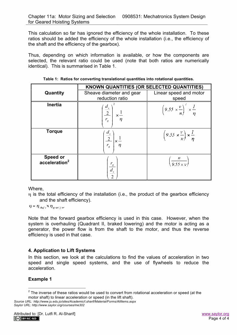
This calculation so far has ignored the efficiency of the whole installation. To these ratios should be added the efficiency of the whole installation (i.e., the efficiency of the shaft and the efficiency of the gearbox). Thus, depending on which information is available, or how the components are selected, the relevant ratio could be used (note that both ratios are numerically identical). This is summarised in Table 1.
Table 1: Ratios for converting translational quantities into rotational quantities.
KNOWN QUANTITIES (OR SELECTED QUANTITIES) Quantity Sheave diameter and gear
reduction ratio Linear speed and motor
speed Inertia
Torque
Speed or acceleration2
Where, η is the total efficiency of the installation (i.e., the product of the gearbox efficiency
and the shaft efficiency).
Note that the forward gearbox efficiency is used in this case. However, when the system is overhauling (Quadrant II, braked lowering) and the motor is acting as a generator, the power flow is from the shaft to the motor, and thus the reverse efficiency is used in that case.
4. Application to Lift Systems In this section, we look at the calculations to find the values of acceleration in two speed and single speed systems, and the use of flywheels to reduce the acceleration. Example 1
2 The inverse of these ratios would be used to convert from rotational acceleration or speed (at the motor shaft) to linear acceleration or speed (in the lift shaft).
Chapter 11a: Motor Sizing and Selection for Geared Hoisting Systems
0908531: Mechatronics System Design
Source URL: http://www.ju.edu.jo/sites/Academic/l.sharif/Material/Forms/AllItems.aspx Saylor URL: http://www.saylor.org/courses/me302 Attributed to: [Dr. Lutfi R. Al-Sharif] www.saylor.org Page 5 of 5
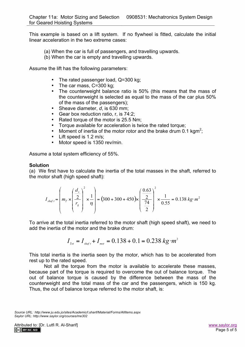
This example is based on a lift system. If no flywheel is fitted, calculate the initial linear acceleration in the two extreme cases:
(a) When the car is full of passengers, and travelling upwards. (b) When the car is empty and travelling upwards.
Assume the lift has the following parameters:
• The rated passenger load, Q=300 kg; • The car mass, C=300 kg; • The counterweight balance ratio is 50% (this means that the mass of
the counterweight is selected as equal to the mass of the car plus 50% of the mass of the passengers);
• Sheave diameter, d, is 630 mm; • Gear box reduction ratio, r, is 74:2; • Rated torque of the motor is 25.5 Nm; • Torque available for acceleration is twice the rated torque; • Moment of inertia of the motor rotor and the brake drum 0.1 kgm2; • Lift speed is 1.2 m/s; • Motor speed is 1350 rev/min.
Assume a total system efficiency of 55%. Solution (a) We first have to calculate the inertia of the total masses in the shaft, referred to the motor shaft (high speed shaft):
To arrive at the total inertia referred to the motor shaft (high speed shaft), we need to add the inertia of the motor and the brake drum:
This total inertia is the inertia seen by the motor, which has to be accelerated from rest up to the rated speed. Not all the torque from the motor is available to accelerate these masses, because part of the torque is required to overcome the out of balance torque. The out of balance torque is caused by the difference between the mass of the counterweight and the total mass of the car and the passengers, which is 150 kg. Thus, the out of balance torque referred to the motor shaft, is:

Chapter 11a: Motor Sizing and Selection for Geared Hoisting Systems
0908531: Mechatronics System Design
Source URL: http://www.ju.edu.jo/sites/Academic/l.sharif/Material/Forms/AllItems.aspx Saylor URL: http://www.saylor.org/courses/me302 Attributed to: [Dr. Lutfi R. Al-Sharif] www.saylor.org Page 6 of 6
We shall assume that the starting torque available from the motor is twice the rated torque, which 25.5·2=51 N·m. Thus, the angular acceleration will be:
This corresponds to a linear acceleration of:
(b) When the car is empty, the inertia of the masses in the shaft referred to the motor shaft (high speed shaft) is:
Thus, the total inertia is:
The out of balance torque will have the same value in this case, as the difference between the counterweight mass and the car mass is 150 kg. However, the out of balance torque in this case will be aiding the motor torque to accelerate the masses, because the car is empty and moving upwards. Thus, the angular acceleration will be:
This corresponds to a linear acceleration of:

Chapter 11a: Motor Sizing and Selection for Geared Hoisting Systems
0908531: Mechatronics System Design
Source URL: http://www.ju.edu.jo/sites/Academic/l.sharif/Material/Forms/AllItems.aspx Saylor URL: http://www.saylor.org/courses/me302 Attributed to: [Dr. Lutfi R. Al-Sharif] www.saylor.org Page 7 of 7
■
As seen from this example, although the acceleration value when fully loaded up was acceptable (1 m·s-2), the acceleration in the other extreme case, empty up was unacceptably high. This is a problem with this type of drive that is driven directly from the supply (i.e., without a variable speed drive), as there is no control over the value of acceleration. To alleviate this problem, a flywheel can be used which will slightly reduce acceleration during full up, and further reduce the acceleration during empty up, as seen below. Example 2 Assume a flywheel with inertia of 0.1 kg·m2 is fitted to the lift in Example 1 above. Calculate the new values of acceleration for the two extreme situations. Solution The total inertia of the system is calculated as follows:
Thus, the angular acceleration will become:
Giving a value of linear acceleration of:
In the empty car moving up scenario, the total inertia of the system will be:
Thus, the angular acceleration will be:
Giving a linear acceleration of:

Chapter 11a: Motor Sizing and Selection for Geared Hoisting Systems
0908531: Mechatronics System Design
Source URL: http://www.ju.edu.jo/sites/Academic/l.sharif/Material/Forms/AllItems.aspx Saylor URL: http://www.saylor.org/courses/me302 Attributed to: [Dr. Lutfi R. Al-Sharif] www.saylor.org Page 8 of 8
■
Adding the flywheel in the last example has had a larger effect on reducing the up empty acceleration than it has on the up full acceleration. The minimum value of acceleration is still acceptable (0.7 m·s-2), and the maximum value of acceleration has come down from 3.16 m·s-2 to 2.1 m·s-2. Thus, the effect of the flywheel has not been just to reduce the acceleration, but also to reduce the variation in acceleration between the maximum and minimum values of acceleration, as shown in Table 2. Table 2: Effect of the flywheel on the acceleration in a lift system.
Up full Down empty Down full Up empty Variation Without the flywheel 1 m·s-2 1.2 m·s-2 2.64 m·s-2 3.16 m·s-2 2.16 m·s-2 With the flywheel 0.71 m·s-2 1 m·s-2 1.85 m·s-2 2.1 m·s-2 1.39 m·s-2
Although the flywheel has reduced the amount of variation between up empty and up full, this variation in acceleration and the bumpy start of this uncontrolled system is a major disadvantage. Problems 1. A two speed lift has the following parameters:
• Car mass = 600 kg; • C/W is 50% balanced; • car-load is 500 kg; • speed is 1.6 m·s-1; • motor speed is 1350 rpm; • motor and brake inertia 0.14 kg·m2; • motor rated torque 58 N·m; • starting torque is two times the rated torque; • overall system efficiency is 57%.
Calculate the acceleration in the up full case. What is the inertia of a flywheel which can be added to the system to reduce the acceleration to 0.9 m·s-2? 2. The car in problem 1 is to be re-designed to accommodate some extra architectural features (e.g., marble floors). This is expected to increase the mass of the car to 1500 kg. What would be the new acceleration with the flywheel? What needs to be done? 3. A lift system has the following parameters:
• C= 800 kg; • C/W is 45% balanced; • car-load is 480 kg;
Chapter 11a: Motor Sizing and Selection for Geared Hoisting Systems
0908531: Mechatronics System Design
Source URL: http://www.ju.edu.jo/sites/Academic/l.sharif/Material/Forms/AllItems.aspx Saylor URL: http://www.saylor.org/courses/me302 Attributed to: [Dr. Lutfi R. Al-Sharif] www.saylor.org Page 9 of 9
• speed is 2.5 m·s-1; • motor speed is 1420 rpm; • motor and brake inertia 0.12 kg·m2; • motor rated torque 58 N·m; • starting torque is two times the rated torque; • overall system efficiency is 60%.
Calculate the acceleration in the up full case. What is the inertia of a flywheel which can be added to the system to reduce the acceleration to 0.9m·s-2?