chapter 11: standards for other aerodrome facilities
TRANSCRIPT

Manual of Standards Part 139—Aerodromes Chapter 11:Standards for Other Aerodrome Facilities
Version 1.2: September 2004 11-1
CHAPTER 11: STANDARDS FOR OTHER AERODROME FACILITIES
Section 11.1: General
11.1.1 Introduction 11.1.1.1 This Chapter contains standards on aspects of aerodrome design and
operations that are not covered elsewhere in this Manual.
11.1.2 Traffic Control Towers 11.1.2.1 Standards for designing, siting, constructing, equipping and maintaining air
traffic control (ATC) facilities are contained in CASR Part 172.
11.1.3 Standards For Siting and Clearance Areas for Airways Facilities on Airports
11.1.3.1 Airways facilities at an airport permit the safe navigation of aircraft within the airspace of an airway, and include; navigation aids along the airway and for approach and landing at aerodromes, communication facilities, meteorological facilities and ATC facilities.
11.1.3.2 The airways facilities for the safe, efficient operation of aircraft in the terminal area surrounding an airport and on the airport manoeuvring area need, in most instances, to be located on or at the perimeter of the aerodrome. Some of these facilities, in particular the precision approach facilities, must be positioned in precise geometric relativity to runways or runway centreline extensions. Most facilities have associated site clearance areas surrounding the site location to ensure proper operation of the facility.
11.1.3.3 The standards herein set out: (a) The general requirement for sites, and the specific site and clearance
area dimensions (for those types of facilities for which it is possible to specify such), for existing facilities; and
(b) The responsibilities of the aerodrome operator for preservation of sites and their clearance areas for planned or existing facilities.
Note: Many of these facilities are provided and maintained by Airservices Australia. Aerodrome operators should also liaise with Airservices Australia on the technical requirements of individual airways facilities.
11.1.3.4 For new facilities follow the manufacturers instructions. 11.1.3.5 Airways facilities at an aerodrome may include any or all of the following:
Federal Register of Legislative Instruments F2010C00657
Chapter 11: Standards for Other Aerodrome Facilities
Manual of Standards Part 139—Aerodromes
11-2 Version 1.2: September 2004
(a) navigation aid facilities ο ILS ο DME ο VOR ο NDB
(b) radar sensor sites (c) air/ground and point-to-point communications systems including radio
bearer systems and satellite communications sites (d) air traffic services centres (e) fire stations (and satellite fire station); and (f) ATC towers.
11.1.4 General Siting Requirements 11.1.4.1 The siting criteria define the minimum requirements for uncompromised
performance of each facility. Non-compliance or infringement of the site criteria and associated clearance areas does not always result in a particular facility being unserviceable or unsafe, but the functions may be degraded. Such degradation may, however, necessitate the facilities removal from service in some instances. Any potential infringement by the aerodrome operator to the criteria for existing or planned facilities is to be referred to Airservices Australia by the aerodrome operator.
11.1.4.2 The general requirements for airways facilities are a finite site for their physical installation, i.e. shelters, foundations, towers, antennae plus a reasonable service area around the physical features. In many instances, there is also a requirement for a clearance zone around this space, in some instances relatively extensive, for the purposed of ensuring transmission of electromagnetic waves without interference from extraneous sources, or for the purpose of unimpeded vision in the cases of ATC towers or RFFS stations.
11.1.4.3 The responsibilities of the aerodrome operator in complying with the requirements of this standard include: (a) the controls on the erection of structures, e.g. buildings, hangars,
fences, roads within specified distances and height limitations, of existing or planned airways facilities;
(b) control on vehicles or aircraft entering, traversing or parking within specified clearance areas; and
(c) ensuring that Airservices Australia is consulted on the effect of proposed aerodrome works or developments on the airways facilities. Even temporary construction works such as stockpiling of materials may have an effect, particularly on precision approach aids.
Federal Register of Legislative Instruments F2010C00657

Manual of Standards Part 139—Aerodromes Chapter 11:Standards for Other Aerodrome Facilities
Version 1.2: September 2004 11-3
11.1.5 Navigation Aid Facilities 11.1.5.1 The location of the radio navigation aids is largely determined by the air route
or approach path on which they are to be used; they cannot normally be moved without some consequential change to or restriction placed on the approach path or air route.
11.1.5.2 These facilities are not to be compared with radio, television or mobile radio facilities. Except for NDBs, radio navigation aids are more complex in terms of the transmitting equipment, the antenna design and the electromagnetic fields which are created about them. The accuracy of the paths defined by a particular navigation aid is determined not only by the transmitting facility but is largely dependent on the reflection of its signals from the objects about the facility; the terrain, vegetation, buildings, power lines, aircraft, other vehicles, fences, ditches, etc. In designing a facility, the position of these objects is taken into account. For example, sites are chosen so that these objects will provide least signal degradation; the vegetation is cleared, the ground levelled in key areas, and power lines may be moved or buried.
11.1.5.3 For the facility to remain a useful part of the airways system, these environmental characteristics have to be maintained and any proposals for change need to be carefully examined.
11.1.5.4 The development constraints set out herein provide guidance to activity and development restrictions in the vicinity of radio navigation aids. In cases where a proposed or planned development is of a significant size, unusual nature or exceeds these restrictions Airservices Australia is to be consulted and written approval obtained before the commencement of any such developments or activities.
11.1.6 VOR Facilities 11.1.6.1 Vehicle movements. Aerodrome roadways, taxiways, public roads,
tramways and railways shall not be closer than a 300 m radius. Vehicles used by aerodrome maintenance staff are not to be parked within a 300 m radius.
11.1.6.2 Restricted area. All unauthorised personnel and vehicles must be kept clear of the facility within a 300 m radius. Wooden signs or wooden fencing only may be used to clearly define the restricted area. The movement of vehicles between the VOR building and VOR antenna is prohibited.
11.1.6.3 Site maintenance. Grass and scrub within 150 m of the site must be mown or cut regularly. Grass cutting equipment is not to be parked within a 300 m radius of the VOR building.
11.1.6.4 Services. All cables (e.g. power and telephone) are to be placed underground within 300 m radius of a VOR facility. Cables can be run above the ground from 300 m to 600 m radius from a VOR, if they are aligned radially to the VOR.
Federal Register of Legislative Instruments F2010C00657

Chapter 11: Standards for Other Aerodrome Facilities
Manual of Standards Part 139—Aerodromes
11-4 Version 1.2: September 2004
11.1.6.5 Clearance zone. No structure, building, trees, fences, towers or power lines is permitted within 600 m radius of the VOR if they will extend above an elevation angle of one degree as seen from the VOR site.
11.1.7 DME Facilities 11.1.7.1 Vehicle movements. No restriction.
11.1.7.2 Restricted area. No restricted areas.
11.1.7.3 Site maintenance. There is no requirement for grass or scrub clearing, however, trees within a radius of 300 m must not be allowed to grow above the height of the DME antenna mounting point on the DME mast.
11.1.7.4 Services. Overhead LV power and control lines are allowable in the vicinity of the DME site provided the clearance requirements of Paragraph 11.1.7.5 are met. Overhead 2 kV-22 kV HV lines must be at least 400 m distant, while HV lines in excess of 22 kV must be at least 1 km distant from the DME antenna system.
11.1.7.5 Clearance zone. Small structures, small buildings, overhead lines and fences are allowable adjacent to the DME antenna location within a 600 m radius, providing that they do not project above the mounting point of the DME antenna to the DME mast.
11.1.7.6 Larger obstructions such as multi-storey buildings, hangers, bridges, etc, may interfere with DME system performance and any proposal to erect large structures above a one degree elevation angle as seen from the DME antenna within a 5 km radius from the DME antenna location may affect the performance of the system.
11.1.8 Instrument Landing System 11.1.8.1 General. There are several components on an instrument landing system:
the localiser, glide path, inner, middle and outer markers, remote monitor and locator beacons. The component facilities perform specific functions and are separately located on the approach path to and alongside the runway they serve. Different siting requirements and restrictions to access and movement apply to each site.
11.1.8.2 Services. Within the site areas all power and control cables must be laid underground.
11.1.8.3 Construction. No construction or variation to access is permitted within the critical or sensitive areas without the prior approval of CASA.
11.1.8.4 Aircraft. Aircraft shall not enter or remain within a critical area whilst the ILS is in use. This condition may be varied if part of an approved procedure.
11.1.8.5 Vehicles and Plant. Vehicles and plant shall not enter nor remain within a critical or sensitive area whilst the ILS is in use.
11.1.8.6 Vehicles operating within the critical area may cause the equipment to automatically shut down. During activities which require access to the critical area, e.g. mowing, the ILS shall be removed from service.
Federal Register of Legislative Instruments F2010C00657

Manual of Standards Part 139—Aerodromes Chapter 11:Standards for Other Aerodrome Facilities
Version 1.2: September 2004 11-5
11.1.8.7 Road Use. Approval may be granted for the use of constructed roadways where the type and size of vehicle has been assessed and determined to be acceptable.
11.1.8.8 Access Control. Access to the critical area shall be controlled by the responsible ATC officer.
11.1.8.9 Signs. Signs shall be provided to delineate the boundaries of the critical area.
11.1.8.10 Critical/Sensitive Areas. The occurrence of interference to ILS signals is dependant on the total environment around the ILS antennas, and antenna characteristics. The environment, for the purpose of developing protective zoning criteria, can be divided into two types of area, the critical areas and the sensitive areas.
11.1.8.11 The critical area is an area of defined dimensions about the localiser and glide path where vehicles, including aircraft, will cause unacceptable disturbances to the ILS performance.
11.1.8.12 The sensitive area is an area extending beyond the critical area where the parking and/or movement of vehicles, including aircraft, may affect the ILS performance.
11.1.9 Localiser 11.1.9.1 Site. The localiser antenna is located on the extended centreline of the
runway typically 400 m from the stop-end. 11.1.9.2 The localiser shelter is generally located 90 m to the side of the antenna
system.
11.1.9.3 Critical area. The critical area for a localiser extends 90 m either side of the runway centreline commencing from 10 m behind the localiser antenna and extending forward to a point of 360 m in front of the antenna (see Figure 11.1-1).
11.1.9.4 Sensitive area. The sensitive area commences at the localiser antenna origin and extends forward in a sector ±10 degrees of the runway centreline. Within this sector obstructions shall be less than 0.5 degrees elevation, when measured from ground level at the antenna base (see Figure 11.1-1).
11.1.9.5 Site preparation. The critical area shall be prepared to have a lateral gradient of not greater than ±1%, longitudinal gradient of not grater than ±1% and shall be graded smooth to within ±75 mm of design levels.
Federal Register of Legislative Instruments F2010C00657

Chapter 11: Standards for Other Aerodrome Facilities
Manual of Standards Part 139—Aerodromes
11-6 Version 1.2: September 2004
365m10m
90m
90m
Clear of Obstructions
0.5º
Clear of Obstructions
Elevation View
LLZ.ANT.
90m
90m
305m
10º
10º 10º
10º
(Approx.)
Localizer building
Localizer antenna
End of Runway
LLZ.ANT.
Plan View
Edges of site area to be graded to natural surface at 5% or less
Site areaLateral gradient ±1%, longitudinal gradient ±1%Smooth to within 75mm of design levels
Within ± 10º splay no obstruction
LOCALIZER SITE LAYOUT
CRITICAL AREA
SENSITIVE AREA
To aerodrome boundary
Ground
Figure 11.1-1: ILS localizer site preparation and restrictions
Federal Register of L
egislative Instruments F2010C
00657

Manual of Standards Part 139—Aerodromes Chapter 11:Standards for Other Aerodrome Facilities
Version 1.2: September 2004 11-7
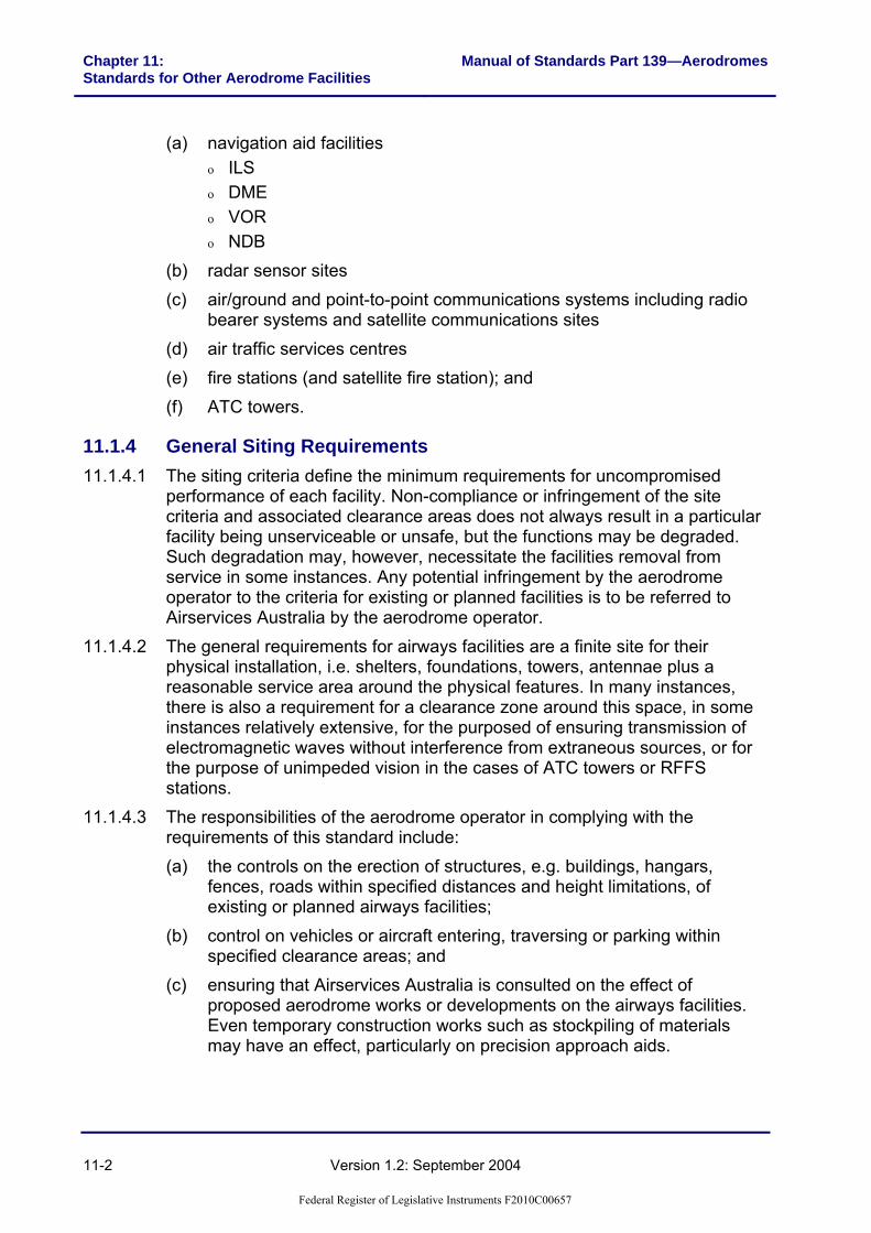
11.1.10 Glide Path 11.1.10.1 Site. Normal practice is to install the glide path system for a threshold
crossing height of 15 m, with a path angle of 3 degrees. The glide path tower should be situated on the non-taxiway side of the runway approximately 300 m back set from the threshold and between 150 m to 175 m from the runway centreline.
11.1.10.2 The special earth mat laid between the glide path antenna and the monitor pick-ups must be inspected at regular intervals. Growth of grass is to be prevented by applying weed killer as necessary.
11.1.10.3 Critical area. The critical area for a glide path extends 700 m forward of the antenna and either side of a line, parallel to the runway centreline, which passes through the antenna tower (See Figure 11.1-2).
11.1.10.4 Sensitive area. The sensitive area includes the critical area plus an area bounded by lines at ±30 degrees to a ray commencing at the antenna and extending parallel to the runway centreline towards the threshold. An allowance of 0.5 degrees elevation is permitted for constructions outside the critical area (See Figure 11.1-1).
11.1.10.5 Remote monitors. Remote monitors are a non-executive monitor of the localiser located in the far field, typically in the area of the middle marker.
11.1.10.6 The sensitive area is detailed in Figure 11.1-3.
Federal Register of Legislative Instruments F2010C00657
Chapter 11: Standards for Other Aerodrome Facilities
Manual of Standards Part 139—Aerodromes
11-8 Version 1.2: September 2004
914m
305m(Approx.)
175m
(App
rox.
)
End of runway pavement
219m
Approx. position of glide path antenna
Edges of site area to be graded to natural surface at 5%
GL. P.ANT
10m
30º
30º
0.5º
Elevation View
Plan View
300m 75m
90m
175m
(A
ppro
x.)
GL.P.ANT.
10m
45º
Site AreaLateral gradient ±1% or less, longitudinal gradient less than ± 1%. No change in magnitude or direction of gradients within site area. Surface to be finished to within ± 76mm of design levels and graded graded smooth.Note 1. The glide path should be installed on the side of the runway remote from taxiways. The glide path site layout may therefore be the mirror image of that shown above.
GLIDE PATH SITE LAYOUT
Restricted area access not permitted without prior approval of ATS
CRITICAL AREAClear of obstructions
Clear of obstructions
SENSITIVE AREA(Used for planning to control erection of buildings)
To aerodrome boundary
Ground
Figure 11.1-2: ILS Glide path site preparation and restrictions
Federal Register of L
egislative Instruments F2010C
00657

Manual of Standards Part 139—Aerodromes Chapter 11:Standards for Other Aerodrome Facilities
Version 1.2: September 2004 11-9
GroundGround
30m
30º
30º
30º
30º
5m
ANT.
ANT.
5m
PLAN VIEW
SIDE ELEVATION
Figure 11.1-3: ILS Remote monitor antenna sensitive area
11.1.11 Marker Beacons 11.1.11.1 Inner marker. The inner marker should be located between 75 m and 450 m
from the threshold and not more than 30 m from the extended centreline of the runway. Care must be taken in siting the inner marker to avoid interference between it and the middle marker.
11.1.11.2 Middle marker. The middle marker should be located 1050 ±150 m from the landing threshold at the approach end of the runway, and not more than 75 m from the extended centreline of the runway.
11.1.11.3 Outer marker. The outer marker should be located 3.9 nautical miles from the threshold of the runway. If this distance is unsuitable, it may be located between 3.5 and 6 nautical miles from the threshold. If the marker is situated off the extended runway centreline, it should be not more than 75 m from it.
11.1.11.4 Obstructions. Buildings, power or telephone lines, or clumps of trees should not extend above an elevation angle of 30 degrees from a point 1.5 m above ground level at the location of the marker beacon antenna.
11.1.11.5 Vehicular movement. No special requirements.
Federal Register of Legislative Instruments F2010C00657

Chapter 11: Standards for Other Aerodrome Facilities
Manual of Standards Part 139—Aerodromes
11-10 Version 1.2: September 2004
11.1.11.6 Services. Within 15 m of the antenna, all power and telephone lines are to be laid underground. Beyond this distance any overhead construction should meet the obstruction limits as above.
11.1.11.7 Electrical interference. No requirements.
11.1.11.8 Restricted area. No special requirements.
11.1.11.9 Maintenance of site. Grass, shrubs, etc., should be kept cut to a reasonable level, e.g. less than 0.6 m. Trees on the site should not be allowed to infringe the obstruction limits as above.
11.1.12 Locator Beacons 11.1.12.1 All requirements as for non-directional beacons below.
11.1.13 Non-Directional Beacons (NDB) 11.1.13.1 Obstructions. The immediate surrounding area within a radius of 150 m of
the antenna should be free of buildings exceeding 2.5 m in any dimension, vegetation should be kept below a height of 0.6 m. Small buildings of substantially non-metallic construction extending less than 2.5 m in any dimension may be erected no closer than 60 m to the antenna.
11.1.13.2 Overhead power and telephone lines serving the NDB should be kept at least 150 m clear of the antenna. Steel towers and masts should subtend elevation angles less than 3 degrees measured from ground level at the centre of the NDB antenna system.
11.1.13.3 Vehicular movements. With the exception of authorised vehicles no vehicle shall approach the antenna within a distance closer than 60 m.
11.1.13.4 Services. Power and telephone cables should be underground to a depth of 0.45 m within 150 m of the antenna.
11.1.13.5 Restricted area. No special requirements. Where necessary, fencing should be provided to keep cattle and horses clear of the earthmat area.
11.1.13.6 Site maintenance. No special requirement other than to keep undergrowth from exceeding a height of 0.6 m and to maintain a neat appearance of the site. Ploughing is not permitted over any portion of the earthmat area. Grazing of sheep is permissible but cattle and horses must be kept clear.
11.1.14 Radar Sensor Sites 11.1.14.1 Site requirements. The site requirement for existing types of radar sensors
is a rectangular area about 50 m by 40 m, including sufficient space for a crane to manoeuvre and an antenna maintenance pad.
11.1.14.2 For new sites, the above dimensions may be reduced, depending on whether or not standby power generation are co-located. However, the antenna maintenance space in which a crane can manoeuvre may be the limiting factor.
Federal Register of Legislative Instruments F2010C00657

Manual of Standards Part 139—Aerodromes Chapter 11:Standards for Other Aerodrome Facilities
Version 1.2: September 2004 11-11
11.1.14.3 Clearance requirements. Radar transmission clearance requirement are intended to prevent the following: (a) Holes in the coverage by new constructions blocking line of sight
between radar and aircraft. Any construction, which geometrically intrudes above the existing skyline as seen by the radar, will have an affect.
(b) Interference with near fields of the antenna, which may disturb the antenna pattern in the far field. This applies within 500 m of most radars.
(c) Diffraction and bending of signals by edges and thin objects which can cause incorrect radar determined location, loss or confusion of radar tracks etc. Likely hazards in this regard are poles such as lighting poles.
(d) Reflections of the radar signals from fixed or mobile surfaces. Reflections cause aircraft to appear on radar screens in more than one location.
11.1.14.4 The following clearance requirements are to be maintained: (a) No intrusion within 1 km of the radar into a height surface 5 m below the
bottom of the antenna. No intrusion between the radar and the possible location of any desired targets, i.e. roughly speaking above 0.5 degrees elevation at any distance.
(b) No metallic or other electrical reflective surfaces anywhere which subtend an angle of more than 0.5 degrees when viewed from the radar, eg. fences, power lines, tanks as well as many buildings. All overhead power lines within 1 km must be aligned radially from the radar or be located at least 10 degrees below horizontal from the antenna.
(c) No radio interference emitters within 2 km having any component of transmission in the radar bands, eg. welders and electrical transmission lines. No electrical transmission lines within following specified distances:
Table 11.1-1
Line capacity Distance 2 kV – 22 kV 400 m
22 kV – 110 kV 1 km
above 110 kV 2 km
(d) Other electronic equipment may be affected by the radar transmissions. Such equipment should not be located where the radars may interfere with their performance.
11.1.14.5 Precautions against Exposure of Personnel to Radio Frequency Radiation from Radar Systems. The primary surveillance radar transmitters on airports radiate high power beams of radio frequency energy. In close
Federal Register of Legislative Instruments F2010C00657
Chapter 11: Standards for Other Aerodrome Facilities
Manual of Standards Part 139—Aerodromes
11-12 Version 1.2: September 2004
proximity to a surveillance radar antenna, the electromagnetic field strengths within the transmitted radar beam may be such that persons could be subjected to radiation exposure levels in excess of the safe limits specified in Australian Standard 2772. Airport staff is therefore to be cautioned against approaching any location within a 500 m radius of a primary radar antenna and which is between 5 m below and 50 m above the horizontal level of the bottom of the antenna.
11.1.15 Communication Facilities 11.1.15.1 Site requirements. The physical site requirements will vary significantly
depending on the type of communications facility, and it is therefore not possible to specify a general requirement (other than for Satellite ground station sites).
11.1.15.2 Clearance requirements. Reliable VHF/UHF communications require a clear line-of-sight path between the base station and aircraft and vehicles using the facilities. The construction of buildings, towers, etc. may prevent reliable communications.
11.1.15.3 Satellite Ground Stations. The site requirement is a square area of dimension 25 m by 25 m. The clearances required around satellite ground stations are shown in Figure 11.1-4.
11.1.15.4 Rescue and Fire Stations. Location of airport fire stations (or satellite fire stations) involves compliance with MOS 139 subpart H requirements on RFFS response times, and therefore generally need to be reasonably centrally located with respect to runway configurations. See MOS 139H for details.
Federal Register of Legislative Instruments F2010C00657

Manual of Standards Part 139—Aerodromes Chapter 11:Standards for Other Aerodrome Facilities
Version 1.2: September 2004 11-13
10º
Clearance angle
Clearance angle
Clearance angle
Clearance angle
10º
C/L of Beam
Towards 160ºLongitude
2m
Satellite azimuth mark
Station mark(Centre of site)
1m
2.4m
6m
Equipment shelter
25m
25m
C/L of Beam
2m chain mesh fence
3.6m standard double gates
Elevation Angle
Azimuth Angle
Figure 11.1-4: Communications Satellite Ground Station Manned Centre Site
Federal Register of Legislative Instruments F2010C00657

Chapter 11: Standards for Other Aerodrome Facilities
Manual of Standards Part 139—Aerodromes
11-14 Version 1.2: September 2004
11.1.16 Ground Earthing Points 11.1.16.1 Where required, the provision of a ground earthing points must be made in
agreement with the fuelling agent. 11.1.16.2 Where ground earthing points are provided, the resistance to earth must not
exceed 10,000 ohms. 11.1.16.3 Where ground earthing points are provided, they must be maintained in
accordance with the procedures set out in paragraphs 11.1.17.1 to 11.1.19.1.
Note: Civil Aviation Order Section 20.9 titled ‘Air Service Operations - Precautions in Refuelling, Engine and Radar Ground Operations’ also contains information on ground earthing points.
11.1.17 Testing of Ground Earthing Points 11.1.17.1 Each ground earthing point must be tested for its electrical resistance, both
as part of the initial installation (or any replacement), six months after the installation (or any replacement), and also thereafter as part of the Aerodrome Technical Inspection.
11.1.17.2 Where testing shows that the earthing points are sound, they must be marked with a 15 cm diameter circle, painted white.
11.1.18 Inspection of Ground Earthing Points 11.1.18.1 The ground earthing points must be inspected as part of the quarterly
technical inspection to ensure that: (a) the ground earthing point is firmly connected to the earthing rod and
seated on the pavement; (b) the earthing rod is firmly embedded in the ground; (c) the fins used for making electrical connections are free from dirt, grease
paint, or any other substances; and (d) no ground earthing points have been buried or removed.
Federal Register of Legislative Instruments F2010C00657

Manual of Standards Part 139—Aerodromes Chapter 11:Standards for Other Aerodrome Facilities
Version 1.2: September 2004 11-15
11.1.19 Remedial Action 11.1.19.1 When the resistance to earth exceeds 10,000 ohms and the ground earthing
point cannot immediately be repaired or replaced, the head of the ground earthing point must either be removed or marked with a 15 cm diameter circle, painted red, to show it cannot be used.
11.1.20 Compass Swinging Site 11.1.20.1 Aircraft compass calibration may be conducted by using approved compass
calibration equipment or by aligning an aircraft on known magnetic headings for the purpose of determining the degree of error in the magnetic compass, commonly referred to as ‘swinging the compass’. The latter method must only be conducted at a suitable compass swinging site.
Note: CAO 108.6 specifies the process control for the calibration of aircraft compasses.
11.1.20.2 Guidance information for the establishment of a compass swinging site is provided in the Advisory Circular (AC).
11.1.21 Automatic Weather Information Stations 11.1.21.1 The location and configuration of the Bureau of Meteorology (BoM) provided
weather information station sites and their dial-up phone numbers, and, as relevant, the VHF broadcast frequencies, are set out in the MET section of ERSA.
11.1.21.2 Current weather information from the site is also available by accessing the BoM internet site at: www.bom.gov.au.
Federal Register of Legislative Instruments F2010C00657

Chapter 11: Standards for Other Aerodrome Facilities
Manual of Standards Part 139—Aerodromes
11-16 Version 1.2: September 2004
11.1.22 Light Aircraft Tie-Down Facilities 11.1.22.1 Light aircraft tie-down facilities may be provided to secure aeroplanes against
possible damage if they are blown off their apron parking position by strong winds.
11.1.22.2 Where provided, tie down facilities must be of adequate strength for the aircraft type being secured. The design of the tie-down facilities should be determined in consultation with an engineering consultant or manufacturer. The tie-down facilities should ideally be fixed to the ground using embedded anchors, and not left loose on the apron surface where they could create an FOD problem.
Federal Register of Legislative Instruments F2010C00657

Manual of Standards Part 139—Aerodromes Chapter 12:Operating Standards for Registered Aerodromes
Version 1.2: September 2004 12-1
CHAPTER 12: OPERATING STANDARDS FOR REGISTERED AERODROMES
Section 12.1: General
12.1.1 Introduction 12.1.1.1 Unlike a certified aerodrome where the aerodrome operating procedures are
regulated through an aerodrome manual, the procedures for a registered aerodrome are simpler.
12.1.1.2 The operator of a registered aerodrome is required to: (a) Ensure that the aerodrome operational information which he or she has
provided and published in ERSA and RDS is current; (b) When it is not, promptly advise pilots, through the NOTAM system. of
changes which may affect aircraft operations; and (c) Submit to CASA an aerodrome safety inspection report conducted by an
approved person, annually or at a timing as agreed by CASA. 12.1.1.3 To ensure that the aerodrome information provided is current, means that the
aerodrome facilities must be maintained to the standard when the aerodrome was registered or if a facility is upgraded to a new standard, to that standard.
12.1.1.4 To be able to promptly advise changes, operators of registered aerodromes need to have personnel and procedures to conduct timely serviceability inspections, identify changed circumstances and make reports.
12.1.1.5 Although formal documentation of all facets of aerodrome operations are not required, it is in the interest of the operator of a registered aerodrome to be able to demonstrate that he or she is discharging the duty of care in providing a safe facility for aircraft operations. To avoid confusion and misunderstanding, all arrangements regarding aerodrome safety functions must be in writing.
12.1.1.6 If a registered aerodrome fails to meet safety requirements, CASA may suspend or cancel the registration. CASA Aerodrome Inspectors may conduct scheduled or unscheduled inspections of the aerodrome to assess whether a registered aerodrome is meeting safety requirements.
12.1.1.7 The standards and procedures of this Chapter are intended to assist operators of registered aerodromes to meet on-going aerodrome safety requirements.
Federal Register of Legislative Instruments F2010C00657

Chapter 12: Operating Standards for Registered Aerodromes
Manual of Standards Part 139—Aerodromes
12-2 Version 1.2: September 2004
12.1.2 Aerodrome Reporting Officer 12.1.2.1 The operator of a registered aerodrome must have in place, experienced or
appropriately trained persons, known as reporting officers, to carry out the aerodrome safety functions. Attributes required include: (a) Knowledge of the standards that the aerodrome has to be maintained to; (b) Mature self-starter who can be relied on to conduct regular serviceability
inspections of the safety elements of the aerodrome; (c) Having the written and oral communication skills to initiate NOTAM or to
communicate aerodrome condition status to ATC, pilots and other aerodrome users.
12.1.2.2 Reporting officers are normally directly under the employ of the operator of the aerodrome. However, at an aerodrome where aerodrome operator’s employees may not be available at all times, other persons may be nominated as reporting officers, for example the local agent of the airline during the period of regular public transport operations conducted by the airline concerned. Before entrusting the reporting function to a person, the aerodrome operator must ensure that the person is trained and has the appropriate attributes.
12.1.2.3 Reporting officers must be provided with appropriate radios in their vehicles so they can maintain a listening watch of aircraft activities on and in the vicinity of the aerodrome during working hours.
12.1.3 Aerodrome Serviceability Inspections 12.1.3.1 Aerodrome serviceability inspections are visual checks of elements of the
aerodrome which may impact on aircraft safety. A checklist of contents of the inspection must be developed, commensurate with the size and complexity of the aerodrome.
Federal Register of Legislative Instruments F2010C00657

Manual of Standards Part 139—Aerodromes Chapter 12:Operating Standards for Registered Aerodromes
Version 1.2: September 2004 12-3
12.1.3.2 The checklist must encompass at least the follow areas: (a) Surface condition of the movement area, including cleanliness (b) Surface condition of the runway, particularly the usability of unsealed
pavements in wet conditions; (c) Markings, markers, wind direction indicators and aerodrome lighting
systems; (d) any obstacles which may infringe the approach, take-off, transitional, inner
horizontal or other surfaces nominated by the procedure designer; (e) Animal or bird activities on and in the vicinity of the aerodrome; (f) Check fences or other devices that prevent persons and vehicles getting
on the movement area; (g) Check currency of any outstanding NOTAM initiated.
Note: Elements of matters to be checked for are similar to those detailed in Chapter 10: Section 10.2.
12.1.4 Frequency of Serviceability Inspection 12.1.4.1 At an aerodrome with daily regular public transport operations, serviceability
inspections must be carried out daily, preferably before the scheduled operations.
12.1.4.2 Additional serviceability inspections must be conducted after significant weather phenomena such as strong wind gust or heavy rain.
12.1.4.3 At an aerodrome without daily regular public transport operations, serviceability inspections may be reduced to before each regular public transport operation or not less than 2 per week, whichever is more.
12.1.5 Record of Inspections and Remedial Actions 12.1.5.1 The operator of a registered aerodrome must maintain an inspection logbook to
demonstrate that inspections have been carried out. Beside recording the inspections, the logbook should also record significant aerodrome upgrading or remedial works.
Federal Register of Legislative Instruments F2010C00657
Chapter 12: Operating Standards for Registered Aerodromes
Manual of Standards Part 139—Aerodromes
12-4 Version 1.2: September 2004
12.1.5.2 The logbook must be kept for at least 12 months or the agreed period of the aerodrome safety inspection, whichever is longer. The logbook must be made available to a CASA Aerodrome Inspector conducting inspection of the aerodrome and to the qualified person who conducts the annual or periodic safety inspection.
12.1.6 Reporting Changes 12.1.6.1 Where a change in the aerodrome conditions requires a NOTAM to be issued
this must be done in accordance with Section 10.3.
Note: A copy of Notification of Changes to Serviceability of a Registered Aerodrome to the NOTAM Office is shown in Section 12.2.
12.1.6.2 Record of NOTAM initiated should be kept for at least a year or the agreed period of safety inspection, whichever is longer.
12.1.7 Aerodrome Works 12.1.7.1 Aerodrome works must be arranged so as not to create any hazard to aircraft or
confusion to pilots. 12.1.7.2 Aerodrome works may be carried out without closing the aerodrome provided
safety precautions are adhered to. 12.1.7.3 Where aerodrome works are carried out without closing the aerodrome, the
aerodrome works safety procedures specified in Chapter 10: Section 10.10 for certified aerodromes are equally applicable to registered aerodromes.
12.1.8 Safety Inspection Report 12.1.8.1 CASR Part 139 requires a registered aerodrome used by aircraft, with more
than 9 passenger seats, to prepare and submit to CASA annually, or at a periodicity as agreed by CASA, a safety inspection of the aerodrome. Matters to be addressed in the report are also prescribed in the regulations.
12.1.8.2 The report must provide a true picture of the state of the aerodrome in its compliance with applicable standards. Where corrective action or necessary improvements are identified, the aerodrome operator must provide a statement of how the corrective action or improvements would be addressed.
Federal Register of Legislative Instruments F2010C00657

Manual of Standards Part 139—Aerodromes Chapter 12:Operating Standards for Registered Aerodromes
Version 1.2: September 2004 12-5
12.1.8.3 For aerodromes used by aircraft with not more than 9 passenger seats, the approach and take-off area would still need to be checked on a regular basis, preferably at least once a year for tree growth or new tall objects. Where another obstacle may become the critical obstacle and affect the published take-off gradient or the threshold location, the checking should be conducted by a person with appropriate technical expertise, such as an approved person.
12.1.9 Reporting of Obstacles 12.1.9.1 If the aerodrome is served by an instrument approach procedure, any
obstacles, or proposed construction, that may infringe the obstacle limitation surface of the aerodrome, or other areas nominated by the designer of the instrument approach procedure, are to be reported to the designer.
Federal Register of Legislative Instruments F2010C00657

Chapter 12: Operating Standards for Registered Aerodromes
Manual of Standards Part 139—Aerodromes
12-6 Version 1.2: September 2004
Section 12.2: Sample Aerodrome Report Form
Federal Register of Legislative Instruments F2010C00657

Manual of Standards Part 139—Aerodromes
Chapter 13:Standards for Aerodromes Intended for Small Aeroplanes Conducting Air
Transport Operations Under CASR 121b
Version 1.2: September 2004 13-1
CHAPTER 13: STANDARDS FOR AERODROMES INTENDED FOR SMALL AEROPLANES CONDUCTING AIR TRANSPORT
OPERATIONS UNDER CASR 121B
Section 13.1: General 13.1.1 Commencement and Introduction 13.1.1.1 The Standards set out in this Chapter come into effect in accordance with
paragraph 1.1.1.2B 13.1.1.1A This Chapter sets out the minimum Standards for aerodromes used in CASR
Part 121B operations, that is air transport operations in aeroplanes with a maximum take-off weight not exceeding 5,700kg. Although these smaller aircraft may use aerodromes which meet the Standards applicable to aerodromes with respect to regular public transport operations by aeroplanes with a maximum take-off weight in excess of 5700kg, the minimum aerodrome standards for operations by such smaller aircraft are those set out in this Chapter.
13.1.1.2 Pursuance to CASR Part 121B, the responsibility of ensuring that an aerodrome is in compliance with CASR Part 139 standards rests with the holder of the AOC. This responsibility cannot be transferred even though some or all of the functions of the aerodrome may be delegated to another person, such as the owner or operator of the aerodrome.
13.1.1.3 Notwithstanding Paragraph 13.1.1.2, persons providing aerodrome facilities or services to aircraft operations have a duty of care to provide a safe facility or service. Unless an aerodrome is certified or registered, CASA does not regulate the operator of the aerodrome. However, activities of the aerodrome operator may be subject to CASA Inspector scrutiny as part of the audit of the AOC holder’s compliance with regulations.
13.1.2 Aerodrome Standards 13.1.2.1 The required physical dimensions and obstacle limitation surfaces (OLS) are set
out in Table 13.1-1.
Runway strip
RunwayApproach and Take-off surface
Approach and Take-off surface
Transitional surface
Transitional surface
Figure 13.1-1: Obstacle limitation surfaces
Federal Register of Legislative Instruments F2010C00657

Chapter 13: Standards for Aerodromes Intended for Small Aeroplanes Conducting Air Transport Operations Under CASR 121b
Manual of Standards Part 139—Aerodromes
13-2 Version 1.2: September 2004
Table 13.1-1: Standards for physical dimensions and obstacle limitation surfaces
Runway and obstacle surfaces
Aeroplanes not exceeding
5,700kg by night
Aeroplanes not exceeding
5,700kg by day
Aeroplanes not exceeding
2,000kg by day
Runway and strip Runway width 18 m 15 m 10 m Runway strip width: - preferred graded - minimum acceptable
graded - graded plus ungraded
80 m
45m 80m
60 m
45m 60m
30 m
60m Runway longitudinal slope 2% 2% 2% Runway transverse slope 2.5% 2.5% 2.5% Runway strip transverse slope
3.0% 3.0% 3.0%
Approach and take-off surfaces
Length of inner edge 80 m 60 m 30 m Distance of inner edge before threshold
60 m 30 m 30 m
Divergence, each side 10% 10% 10% Length of surface 2500 m 1600 m 900 m Slope 4% 5% 5% Transitional surface Slope (to 45 m in height) 20% 20% 20% Inner horizontal surface Height 45 m 45 m 45 m Radius from runway strip 2,500 m 2,000 m 2,000 m
Note: At aerodromes with 10m wide runways, the aircraft operator or pilot in command should take into account the effects of crosswind.
Federal Register of Legislative Instruments F2010C00657

Manual of Standards Part 139—Aerodromes
Chapter 13:Standards for Aerodromes Intended for Small Aeroplanes Conducting Air
Transport Operations Under CASR 121b
Version 1.2: September 2004 13-3
Inner horizontal surface
Runway and Runway strip
Inner horizontalInner horizontal Transitional Transitional
Runway strip
Figure 13.1-2: OLS cross-section
13.1.2.2 Obstacles. Where an aeroplane operation is affected by the presence of obstacles, the matter needs to be brought to the attention of the relevant CASA office, which will determine obstacle marking and lighting requirements and any operational limitations.
13.1.2.3 Runway length. The runway length requirement varies depending on aircraft type and local geography. It is necessary to ensure that the runway length provided is adequate for the most demanding aeroplane (not necessarily operating to maximum take-off weight) that the aerodrome is intended to serve.
13.1.2.3A Runway strip. The runway strip may consist of a graded portion and an ungraded portion in cases where it is impractical to grade the entire runway strip. The impracticability of complying with specified runway graded width requirements will depend on the circumstances of each individual case. Aerodrome operators should direct any questions about this issue to their nearest CASA area office.
13.1.2.4 Clearways and stopways. If a clearway or stopway is provided to supplement the runway length, it must be provided in accordance with the standards for clearways and stopways specified in Chapter 6.
13.1.3 Aerodrome Markings 13.1.3.1 Aerodrome markings or markers must be provided. Sealed surfaces are
normally marked by paint markings and unsealed surfaces by markers.
Federal Register of Legislative Instruments F2010C00657

Chapter 13: Standards for Aerodromes Intended for Small Aeroplanes Conducting Air Transport Operations Under CASR 121b
Manual of Standards Part 139—Aerodromes
13-4 Version 1.2: September 2004
°
°°°°
°°°°
°°
Detail 1
Apron area Wind indicator
Signal circle
See Detail 1
Runway
Runway strip
Figure 13.1-3: Aerodrome markings
Federal Register of L
egislative Instruments F2010C
00657

Manual of Standards Part 139—Aerodromes
Chapter 13:Standards for Aerodromes Intended for Small Aeroplanes
Conducting Air Transport Operations Under CASR 121b
Version 1.2: September 2004 13-5
13.1.3.2 For a sealed runway, the runway thresholds must be painted in accordance with Paragraph 8.3.8. A runway centreline marking is not required on runways which are 18 m wide or less. White painted runway side stripes, 0.3 m wide, should be provided if there is a lack of contrast between the runway surface and the surrounding area.
13.1.3.3 On unsealed runways, where the runway strip is not maintained to the normal runway grading standards, the runway must be marked using cone markers. Where both the runway and the runway strip are prepared suitable for aircraft operations, either the runway or the runway strip may be marked. Where the runway is not marked using cone markers, the threshold locations should be marked using white cones appropriately positioned in the shape of a └──┘.
Note: Where cone markers are used they may be held down using tent pegs or similar, provided the pegs do not pose a hazard to aircraft or compromise the frangibility of the marker.
13.1.3.4 For both sealed and unsealed runways, the runway strip should also be marked by using cones, gable markers, tyres, or 200 litre drums cut in half along their length and placed with the open side down, or something similar. These runway strip markers should be white in colour.
Note: Runway cone markers should have a 0.4 m base diameter and be 0.3 m in height. Runway strip cone markers should have a 0.75 m base diameter and be 0.5 m in height. Gable markers should be 3 m in length.
13.1.3.5 Cone or similar size markers need to be spaced not more than 90 m apart. Gable or similar size markers need to be spaced not more than 180 m apart.
13.1.3.6 Where the edges of unsealed taxiways or aprons might not be visually clear to pilots, markers may be provided in accordance with Section 8.2.
13.1.4 Aerodrome Lighting 13.1.4.1 Where a runway is intended for night operations, the runway must be
provided with runway edge lighting, spaced laterally at 30 – 31m apart, and longitudinally at approximately 90m apart. The edge lights on each side must present two parallel straight rows equidistant from the runway centreline. The lights indicating both ends of the runway must be at right angles to the runway centreline. See Figure 13.1-4 for a typical layout of runway lights.
13.1.4.2 Where there is no permanent electricity supply, the following may be used: (a) lights producing white light and powered by portable generators,
batteries, or similar power sources; or (b) flares.
Federal Register of Legislative Instruments F2010C00657

Chapter 13: Standards for Aerodromes Intended for Small Aeroplanes Conducting Air Transport Operations Under CASR 121b
Manual of Standards Part 139—Aerodromes
13-6 Version 1.2: September 2004
90m
30mRunway
Figure 13.1-4: Aerodrome lighting
13.1.5 Wind Direction Indicators 13.1.5.1 The standard wind direction indicator is a tapering fabric sleeve (wind sock),
3.65 m long and white in colour. It must be located such that it is clearly visible from the air. It must also be located clear of the 1:5 (20%) transitional surface.
13.1.5.2 If the aerodrome is intended for night operations, the wind direction indicator must be provided with illumination.
13.1.5.3 To enhance sighting of the wind direction indicator from the air, the wind direction indicator must be located within a circular area 15 m in diameter, appropriately blackened or provided with a contrasting colour, and bounded by 15 equally spaced white markers.
13.1.6 Ground Signal and Signal Area 13.1.6.1 A ground signal area, consisting of a circle, blackened or provided with
contrasting colour of 9 m in diameter marked by 6 equally spaced white markers must be provided near the wind direction indicator for the purpose of displaying ground signals to pilots.
13.1.6.2 Marking of unserviceability of aerodrome. A white cross with each arm 6 m in length and 0.9 m in width must be displayed on the signal circle when the aerodrome is closed to aircraft operations.
Federal Register of Legislative Instruments F2010C00657

Manual of Standards Part 139—Aerodromes
Chapter 13:Standards for Aerodromes Intended for Small Aeroplanes
Conducting Air Transport Operations Under CASR 121b
Version 1.2: September 2004 13-7
6m
0.9m
0.9m
Figure 13.1-5: Total unserviceability marking
13.1.7 Runway and Runway Strip Conditions 13.1.7.1 The surface of the runway and runway strip need to be maintained to
minimise adverse effects on aeroplane operations, as follows: Table 13.1-2
Surface Runway Runway strip Sealed surface After compaction, the
surface is to be swept clean of loose stones
N/A
Height of grass • Sparse 450 mm 600 mm • Medium 300 mm 450 mm • Dense 150 mm 300 mm
Size of loose stones • Isolated stones on natural
surface 25 mm 50 mm
• Constructed gravel surface 50 mm 75 mm • Surface cracks 40 mm 75 mm
Federal Register of Legislative Instruments F2010C00657

Chapter 13: Standards for Aerodromes Intended for Small Aeroplanes Conducting Air Transport Operations Under CASR 121b
Manual of Standards Part 139—Aerodromes
13-8 Version 1.2: September 2004
13.1.7.2 The surface of the unsealed runway must not have irregularities, which would adversely affect the take-off and landing of an aircraft.
Note: An empirical test for runway riding quality is to drive a stiffly sprung vehicle such as a medium size utility or unladen truck along the runway at not less than 65 kph. If the ride is uncomfortable, then the surface needs to be graded and levelled.
13.1.8 Aerodrome Serviceability Reporting 13.1.8.1 If the aerodrome is not provided with an Airservices Australia NOTAM
service, the AOC holder needs to establish, in concert with the aerodrome operator, a reporting system such that the pilot can be notified of any changes to the aerodrome serviceability status, preferably before embarking on the journey.
13.1.8.2 The aerodrome operator has a duty of care to provide information that is as accurate as possible. This would require physical inspection of the aerodrome, ideally before the departure of the airline’s aeroplane from its base aerodrome, but always before the arrival of the aeroplane. To maintain the accuracy of the aerodrome serviceability status, it is essential that the aerodrome be inspected after strong wind or rain. The information provided should include: (a) runway surface condition: dry, wet, soft, or slippery; (b) runway strip condition: any obstruction, undue roughness, visibility of
markers; (c) wind direction indicator: if torn or obstructed; (d) approach and take-off areas: if there are objects close to or above the
obstacle surfaces; (e) other hazardous condition or object known to the aerodrome operator,
e.g. animal or bird hazard. 13.1.8.3 If the aerodrome is not published in AIP-ERSA, the AOC holder’s Operations
Manual should indicate clearly the aerodrome operator’s contact details for serviceability status reports.
Federal Register of Legislative Instruments F2010C00657

Manual of Standards Part 139—Aerodromes
Chapter 13:Standards for Aerodromes Intended for Small Aeroplanes
Conducting Air Transport Operations Under CASR 121b
Version 1.2: September 2004 13-9
Note: It is important that the person performing the inspection and reporting duties has a working knowledge of the aerodrome safety requirements and understands clearly his or her responsibilities.
13.1.8.4 For unsealed landing areas, serviceability is often affected by rain. Where the aerodrome is deemed too wet for aeroplane operations, the aerodrome operator needs to display the unserviceability signal, and notify the airlines accordingly. When in doubt, always err on the side of safety.
Federal Register of Legislative Instruments F2010C00657

Federal Register of Legislative Instruments F2010C00657

Manual of Standards Part 139—Aerodromes
Chapter 14:Radio Communication Facilities Provided by an Aerodrome Operator
Version 1.2: September 2004 14-1
CHAPTER 14: RADIO COMMUNICATION FACILITIES PROVIDED BY AN AERODROME OPERATOR
Section 14.1: General
14.1.1 Introduction 14.1.1.1 Subpart F of CASR Part 139 prescribes the provision of certain types of radio
communication facilities at particular aerodromes for the purpose of enhancing the safety of air navigation. The radio communication facility required may be either a Certified Air/Ground Radio Service or a Frequency Confirmation System.
14.1.1.2 This Chapter specifies the requirements and the standards for the provision of the above two types of radio communication services.
14.1.2 Definitions and Abbreviations 14.1.2.1 When the following terms or abbreviations are used in this Chapter, they
have the meaning given:
AAIS: Automatic Aerodrome Information Service means a service that provides current, routine information to aircraft arriving at or departing from an aerodrome by means of repetitive broadcasts on a discrete frequency.
AFRU: Aerodrome Frequency Response Unit.
Certified Air/Ground Radio Operator (CA/GRO): A person certificated under regulation 139.430 as a CA/GRO.
CTAF: Common Traffic Advisory Frequency
Frequency Confirmation System means a ground radio system for an aerodrome that, if it receives a transmission from an aircraft on the MBZ frequency or the CTAF for the aerodrome, sends a signal or message to the aircraft confirming that the transmission has been received.
MBZ: Mandatory Broadcast Zone
Relevant Traffic: Aircraft that the CA/GRO knows to be operating within the MBZ and that may constitute a hazard to a broadcasting aircraft.
VHF: Very High Frequency
Federal Register of Legislative Instruments F2010C00657

Chapter 14: Radio Communication Facilities Provided by an Aerodrome Operator
Manual of Standards Part 139—Aerodromes
14-2 Version 1.2: September 2004
Section 14.2: Certified Air/Ground Radio Services
14.2.1 Application to be a CA/GRO 14.2.1.1 To perform the functions of a CA/GRO, the operator must hold a CA/GRO
certificate issued by CASA (CASA Form 716).
14.2.2 Qualifications 14.2.2.1 The primary purpose of a CA/GRS is to enhance the safety of air transport
aircraft operations by the provision of relevant traffic information. This aspect of the service requires CA/GROs to have had specialised training and experience. Therefore, applicants for the issue of a CA/GRO Certificate must hold, or have held within the last ten years, an ICAO recognised Air Traffic Controller licence or an Australian Flight Service Officer licence.
14.2.2.2 The application form for a CA/GRO certificate is CASA Form 715. Completed application forms should be sent to the CASA Area Office (attention Licensing Officer) closest to the applicant’s place of residence.
14.2.2.3 After receiving an application, before issuing a CA/GRO certificate, CASA must: (a) confirm the applicant’s identity; and (b) confirm that the applicant meets the appropriate pre-requisite licence
qualification. 14.2.2.4 If the applicant meets the licence qualification, CASA will issue the applicant
with a Certified Air/Ground Radio Operator Certificate (CASA Form 716). 14.2.2.5 A CA/GRO Certificate is valid for 10 years from the date of issue.
14.2.3 CA/GRS Operating Standards and Procedures 14.2.3.1 A CA/GRS must provide the following services to aircraft within airspace
designated as an MBZ area in which the aerodrome is located: (a) advice of relevant air traffic in the MBZ airspace or on the aerodrome; (b) aerodrome weather and operational information, including:
(i) wind speed and direction; (ii) the runway preferred by wind or noise abatement requirements; (iii) runway surface conditions; (iv) QNH; (v) temperature; (vi) cloud base and visibility; (vii) present weather; (viii) other operational information; (ix) for departing aircraft, a time check;
Federal Register of Legislative Instruments F2010C00657

Manual of Standards Part 139—Aerodromes
Chapter 14:Radio Communication Facilities Provided by an Aerodrome Operator
Version 1.2: September 2004 14-3
(x) call-out of the aerodrome emergency services; (xi) provide aerodrome information to pilots who telephone the service.
14.2.3.2 A CA/GRO may also provide other information requested by pilots. 14.2.3.3 The decision to use, or not to use, information provided by a CA/GRO rests
with the pilot in command. 14.2.3.4 A permanent CA/GRS must be provided with the following facilities and
documentation: (a) a suitable work area that provides the operator with a full view of the
manoeuvring area and circuit area; (b) two-way VHF radio communications; (c) an AAIS; (d) a telephone; (e) a means of receiving NOTAM; (f) instrumentation that meets Bureau of Meteorology and ICAO Annex 3
standards for aviation use, to provide the following meteorological information: (i) wind direction and speed (2 minute averaging); Instrumentation
measurement accuracy to be: Direction ±5 degrees; Speed ±1 kt up to 20 kt; = ±5% above 20 kt.
(ii) QNH (measured to within 0.1 hPa and rounded down to the next whole integer; eg 1010.9 hPa is reported as 1010 hPa;
(iii) air temperature (measured to within 0.5 degrees Celsius and rounded up to the next whole degree Celsius e.g. 12.5 degrees C is reported as 13 degrees C.
(g) current aeronautical documentation, NOTAM, and charts appropriate to IFR and VFR operations within the MBZ;
(h) the Aerodrome Emergency Plan (AEP) for the aerodrome. 14.2.3.5 A CA/GRO must use the standard aviation communication techniques and
phraseology set out in AIP. 14.2.3.6 A CA/GRS call-sign will be the location name of the aerodrome followed by
the word ‘Radio’. 14.2.3.7 The aerodrome operator must provide NOTAM advice to AIS of the
establishment of, or any changes to, a CA/GRS.
Federal Register of Legislative Instruments F2010C00657
Chapter 14: Radio Communication Facilities Provided by an Aerodrome Operator
Manual of Standards Part 139—Aerodromes
14-4 Version 1.2: September 2004
14.2.4 Broadcasting of Aerodrome Information on AAIS 14.2.4.1 Aerodrome Information must be broadcast on the AAIS in the following order:
• preferred runway
• wind direction and speed
• runway surface conditions
• QNH
• temperature
• cloud base and visibility
• present weather or CAVOK
• aerodrome operational information
Federal Register of Legislative Instruments F2010C00657

Manual of Standards Part 139—Aerodromes
Chapter 14:Radio Communication Facilities Provided by an Aerodrome Operator
Version 1.2: September 2004 14-5
Section 14.3: Frequency Confirmation System
14.3.1 Requirement for Frequency Confirmation System 14.3.1.1 At all non-controlled aerodromes located in an MBZ, and at those
non-controlled aerodromes in CTAF areas which are used not less than 5 times per week by aircraft engaged in air transport operations that have a maximum passenger seating capacity greater than nine, a ground-based frequency confirmation system is required. This requirement may be practically satisfied by one of the following facilities: (a) a certified air/ground radio service (CA/GRS); or (b) an aerodrome frequency response unit (AFRU); or (c) a Unicom service.
14.3.2 Aerodrome Frequency Response Unit (AFRU) 14.3.2.1 The AFRU is an electronic, ground based, aviation safety enhancement
device, intended for use on the CTAF or MBZ frequency at non-controlled aerodromes. It is essentially an internally controlled VHF transceiver with a pre-recorded message transmission capability. AFRU transmissions are triggered when the AFRU receiver detects aircraft transmissions on the correct aerodrome frequency. This response capability is intended to reduce the incidence of incorrect VHF radio frequency channel selection by pilots. If the pilot is aware of the presence of an AFRU in a CTAF area or MBZ, the AFRU will assist in alerting pilots to these situations by providing an automatic transmission on the aerodrome frequency to confirm the receipt of a transmission by an aircraft within radio range. The confirming AFRU transmission will be either a short pre-recorded voice message (e.g. aerodrome name followed by MBZ or CTAF (as relevant), or a short (300 millisecond) tone burst, depending upon radio transmission activity by aircraft operating on that frequency in the preceding 5 minutes, and the form of the pilot’s transmission to the AFRU.
14.3.2.2 An AFRU may also have an optional facility incorporated to operate the runway lights during hours of reduced light and darkness.
14.3.3 Use of the AFRU 14.3.3.1 The AFRU will be suitable for installation at non-controlled aerodromes. It
may also be utilised at those aerodromes which are controlled during busier traffic hours, and which become an MBZ after hours during control tower closure. (In this latter role, the AFRU must only be activated during the hours when the tower is closed; for that purpose the AFRU must have a remote activation capability).
Federal Register of Legislative Instruments F2010C00657

Chapter 14: Radio Communication Facilities Provided by an Aerodrome Operator
Manual of Standards Part 139—Aerodromes
14-6 Version 1.2: September 2004
14.3.4 Operating Performance Requirements of AFRU 14.3.4.1 When an aircraft operating in radio range of the AFRU makes a transmission
(radio broadcast or unmodulated carrier burst) on the aerodrome frequency, the AFRU must be able to detect the presence of aircraft VHF carrier transmissions of 2 seconds or more in duration, and, at the end of the aircraft transmission, it must automatically respond with either one of the following types of transmissions on that frequency: (a) A pre-recorded short voice message, (normally taking the form of the
aerodrome location) if there has been no other received aircraft transmissions in the previous 5 minutes; or
(b) A short (300 ms) tone burst if any aircraft transmissions have been received in the previous 5 minutes.
14.3.4.2 In addition, the AFRU must also be able to detect and respond to any aircraft transmissions which consist of three sequential carrier bursts over a five second period, with the pre-recorded voice message as at (a) above, regardless of radio transmission activity by aircraft in the last 5 minutes.
14.3.5 AFRU Technical Specification 14.3.5.1 Australian Communications Authority (ACA) Type Approval: Units must
meet the technical requirements of, and be certified as complying with, the Australian Communications Authority Equipment Compliance Requirement ECR 203A for Amplitude Modulated Transmitter/Receivers (Base and Mobile) for 25 kHz Carrier Frequency Separation in the Aeronautical Frequency Band 118 - 137 MHz.
14.3.5.2 Frequency Coverage: 118.000 – 136.975 MHz
14.3.5.3 Frequency Selection: Front panel pre-selectable channels for receiver and transmitter with frequency readout of each channel. All frequencies in the range to be selectable in 25 kHz steps.
14.3.5.4 Channel Separation: 25 kHz.
14.3.5.5 Modulation: Amplitude Modulation; depth of modulation to be set at 85% for voice transmissions; 10% for tone burst transmissions.
14.3.5.6 Operating Temperature Range: -10 to +65 degrees Centigrade.
14.3.5.7 Carrier Frequency Stability: Better than or equal to 0.002%.
14.3.5.8 Receiver Sensitivity: S/N ratio > 10 dB for input signal of 2 μV (-101 dBm). Receiver sensitivity to be adjustable between 2 μV and 5 μV.
14.3.5.9 Receiver Selectivity: Unit to operate satisfactorily for all received carrier frequencies within 0.005% of any selected frequency.
14.3.5.10 Transmitter Radiated Power Output: Minimum 2 watts ERP, adjustable to achieve 75 μV/m (-109 dBW/m2) field strength at the limit of the required coverage area (20 NM line of sight). Maximum power output shall not exceed 5 watts ERP.
Federal Register of Legislative Instruments F2010C00657

Manual of Standards Part 139—Aerodromes
Chapter 14:Radio Communication Facilities Provided by an Aerodrome Operator
Version 1.2: September 2004 14-7
14.3.5.11 RF Polarisation: Vertical.
14.3.5.12 Transmitter Recorded Voice Message: 8 seconds minimum capacity. Audio transmissions to be clear and intelligible. Length of carrier transmission not to exceed the recorded voice message time, i.e. carrier must not continue after the voice modulation ceases.
14.3.5.13 Annunciation Timing: The timing of the commencement of the transmitted recorded voice message or the tone burst is to be less than 0.5 second after the end of the aircraft transmission.
14.3.5.14 Transmitter Beepback Tone: 1000 Hz, 300 millisecond tone burst.
14.3.5.15 Power Supply: 220–240 V AC 50 Hz power source shall automatically changeover to internal or external battery stand-by power capable of operating the unit without interruption for 24 hours assuming the load is two voice responses per hour during the 24 hour period.
14.3.5.16 Fault Detection/Timeout and Alarm: In the event of an internal fault condition that results in continuous (jammed) transmission of the VHF carrier, the unit shall internally detect the continuous transmission within one minute and shut down or recycle the unit. Front-panel mounted alarm readout shall provide notification of this fault condition. Indication of the presence or failure of AC mains power, and changeover to operation on the stand-by battery, shall also be clearly provided by front panel indicators. (If an external power supply is used, the indication may be located on the power supply).
14.3.5.17 Remote Activation: The unit shall be capable of remote activation by an external control function such as a timing device. The external function shall be connected via socket connection. The stand-by batteries of the unit shall remain fully charged during the time that the unit remains remotely activated.
14.3.5.18 Reliability: Design reliability level of the unit shall be in keeping with its safety enhancement function. Design MTBF is to be a minimum of 10000 hours. The AFRU shall consist entirely of solid-state components, with the exception of switching relays (if any).
14.3.5.19 Maintainability: The unit shall be constructed so that fault restoration can be carried out in the field by module/circuit card replacement. Design MTTR shall be less than 72 hours.
14.3.5.20 Construction: Units shall be robustly constructed for either rack mounting, panel mounting or stand-alone bench mounting. All status indicators shall be front panel mounted. Controls, adjustments (other than pre-set adjustments), recording controls, frequency selectors, etc. shall be accessible. Frequency selectors shall clearly indicate the frequency selected and be set up so that it is not possible to inadvertently change frequency by a person brushing past the unit.
14.3.5.21 Mains Connection Approval: Units shall be approved for connection to single-phase 240 VAC power supply by an Australian electrical supply authority. (This does not apply if units are powered by DC sourced from a separate power supply).
Federal Register of Legislative Instruments F2010C00657

Chapter 14: Radio Communication Facilities Provided by an Aerodrome Operator
Manual of Standards Part 139—Aerodromes
14-8 Version 1.2: September 2004
14.3.5.22 Installation, Operation and Maintenance Handbook: Each unit shall have an accompanying Handbook which provides clear instructions covering all aspects of the Installation, Operation, Routine Maintenance, and Fault Finding requirements. The Operation section of the handbook shall consist of step-by-step instructions.
14.3.5.23 Maintenance: Aerodrome operators are required to carry out routine maintenance of the AFRU in accordance with the maintenance instructions in the Installation, Operation and Maintenance Handbook.
14.3.6 AFRU with PAL Features 14.3.6.1 Optional Additional AFRU Function - Pilot-Activated Lighting Control:
Optional additional functionality may be provided with the AFRU unit to provide for aircraft actuated operation of the aerodrome lights at the aerodrome at which the AFRU is located, during night hours or other times of low natural light levels. This option shall emulate the function of the existing PAL circuitry, but permit operation on the CTAF or MBZ frequency.
14.3.6.2 The Pilot Activated Lighting (PAL) option includes a light sensor mounted remotely from the AFRU. During the time the light sensor detects that the natural light intensity is less than a preset level (adjustable on the AFRU unit), and on receipt of an aircraft transmission of three carrier bursts (three PTT clicks) over a five-second period, the AFRU will provide separate relay outputs to operate the airport lighting circuitry (runway lights and illumination of the wind indicator) at the aerodrome. The AFRU will then transmit the standard reply of the normal pre-recorded voice message (the aerodrome name and MBZ or CTAF), followed by the additional recorded voice message of “runway lights on”. The runway lights will operate for a period of either 30 minutes or 60 minutes. The operating period of either 30 minutes or 60 minutes will be preset within the unit. Ten (10) minutes prior to the end of the 30 or 60 minutes period, the windsock light will flash at 1 second intervals and the MBZ/CTAF response, followed by the announcement "runway lights 10 minutes remaining" will be broadcast. At any time during the period of time that the lights are operated, receipt of a further transmission of three carrier bursts shall reset the timing period back to either 30 or 60 minutes.
14.3.7 Technical Specifications for Optional Pilot-Activated Lighting Control
14.3.7.1 Fail-safe Relay Output Switching of Runway and Windsock: Fail-safe switching of runway and windsock outputs to be provided. Outputs to be relay controlled, +12 VDC, for driving remote lighting circuits. (Other configurations to match aerodrome lighting circuitry are permissible, but must be fail-safe, i.e. in the event of failure of the AFRU, the aerodrome lights will be actuated and remain actuated).
14.3.7.2 Ambient Light Sensor: The ambient light sensor device is to be infinitely adjustable from full darkness to bright daylight. Preset control to be located in the AFRU unit, or in the sensor housing.
Federal Register of Legislative Instruments F2010C00657

Manual of Standards Part 139—Aerodromes
Chapter 14:Radio Communication Facilities Provided by an Aerodrome Operator
Version 1.2: September 2004 14-9
14.3.7.3 Operation: The PAL output will activate on receipt of 3 correct PTT bursts (as per standard AFRU). If ‘dark’ =< pre-set darkness level, the normal MBZ/CTAF response message will be transmitted, followed by one of two messages: “runway lights on" message if the lights are activated, or “no runway lights”, depending on whether or not lights have actually illuminated. This is to be sensed in the AFRU by a signal output by a current transducer in the lighting circuitry, and shall only confirm lights on if the runway lighting system is drawing current.
14.3.7.4 Timing: Timings shall emulate the existing PAL system in use, i.e. 30 or 60 minutes preset for lights on, windsock lighting flashes at 1 second rate for the last 10 minutes, and shall be microprocessor controlled within the AFRU unit. Timings to be internally preset. Timer countdown to recommence on receipt of further transmission of 3 PTT bursts during the period that the lights are in operation.
14.3.8 AFRU+PAL Commissioning Flight Test 14.3.8.1 A flight check of the AFRU and the optional PAL function shall be to the
satisfaction of a CASA inspector. The flight test will ensure the functionality of the AFRU and optional PAL at appropriate points on the aerodrome and out to the limits of the relevant CTAF area or MBZ area.
14.3.8.2 On the ground: (a) check activation of AFRU and PAL from the parking apron(s) of the
aerodrome. (b) check all specified functionality of the AFRU and PAL option.
14.3.8.3 In the air: (a) check proper performance of AFRU at line of sight distances out to
20 NM radius of the aerodrome at altitudes of 3,000 to 5,000 feet AGL. (b) check that AFRU Receiver sensitivity and Transmitter power levels are
adjusted to ensure that the AFRU does not activate, and does not transmit, beyond approx 30 NM radius.
(c) check that voice and tone responses are clear and legible. Check that three microphone clicks of 1 second ON, 1 second OFF within 5 second period will activate voice response. (Tolerance on 1 second ON or OFF is 0.5 seconds).
(d) ensure that the AFRU does not trigger falsely during aircraft transmissions. Ensure that no interruptions occur to aircraft transmissions by false triggering of the AFRU during the aircraft transmission.
Federal Register of Legislative Instruments F2010C00657

Chapter 14: Radio Communication Facilities Provided by an Aerodrome Operator
Manual of Standards Part 139—Aerodromes
14-10 Version 1.2: September 2004
(e) check and ensure proper operation of the PAL option as follows: (i) ensure lights are activated by three microphone clicks at a radius
of 15 NM in line-of-sight from the aerodrome, to altitudes of 3,000 to 5,000 feet AGL.
(ii) ensure that lights remain activated for either 30 minute or 60 minute preset period after activation.
(iii) ensure receipt of correct recorded voice responses after activation.
(iv) ensure that illuminated wind indicator flashes 10 minutes before the completion of the 30 or 60 minute period of operation of the lights.
(v) ensure that lights are reset for the preset 30 or 60 minutes period following an aircraft transmission of three microphone clicks at any time within the preset 30 or 60 minutes period.
Federal Register of Legislative Instruments F2010C00657

Manual of Standards Part 139—Aerodromes
Chapter 14:Radio Communication Facilities Provided by an Aerodrome Operator
Version 1.2: September 2004 14-11
Section 14.4: Unicom Services
14.4.1 General 14.4.1.1 Unicom (Universal Communications) services are non-ATS radio
communication services provided on an MBZ frequency or CTAF to enhance the value of information normally available about a non-controlled aerodrome. A Unicom service is not a Certified Air/Ground Radio Service.
14.4.1.2 The primary function of the frequencies (MBZ/CTAF) used for Unicom services is to provide the means for pilots to exchange traffic information for separation purposes. Unicom services, being a secondary use of these frequencies, must not inhibit the exchange of aircraft to aircraft traffic information.
14.4.1.3 Participation in Unicom services by an aerodrome operator, whether for the purposes of a frequency confirmation system or otherwise, is to be limited to the exchange of radio messages concerning: (a) confirmation of the CTAF/MBZ frequency selected by aircraft; (b) general aerodrome weather reports; (c) aerodrome information; (d) estimated times of arrival and departure; (e) passenger requirements; (f) aircraft refuelling arrangements; (g) maintenance and servicing of aircraft including the ordering of urgently
required parts; (h) unscheduled landings by aircraft.
14.4.1.4 General aerodrome weather reports provided by a Unicom operator are to be limited to simple, factual statements about the weather, unless the Unicom operator is authorised by CASA to make meteorological observations.
Federal Register of Legislative Instruments F2010C00657