chapter 11 photonic materials for holographic...
TRANSCRIPT

Chapter 11Photonic Materials for HolographicSensing
Monika Zawadzka, Tatsiana Mikulchyk, Dervil Cody,Suzanne Martin, Ali Kemal Yetisen,Juan Leonardo Martinez-Hurtado, Haider Butt, Emilia Mihaylova,Hussein Awala, Svetlana Mintova, Seok Hyun Yunand Izabela Naydenova
Abstract Holography is a practical approach to fabricating optical sensors forapplications in the detection of chemical analytes and physical changes.Holographic sensors incorporate diffraction gratings within functionalized polymersor natural organic polymer matrices, that allow indirect optical measurements ofphysical and chemical stimuli. The advantages of holographic sensors over otheroptical sensors are the ability to produce three-dimensional (3D) images andamenability to mass manufacturing at low-cost. The aim of this chapter is to(1) describe the principle of operation of holographic sensors (2) describe the
M. Zawadzka � T. Mikulchyk � D. Cody � S. Martin � E. Mihaylova � I. Naydenova (&)Centre for Industrial and Engineering Optics, School of Physics, College of Sciences andHealth, Dublin Institute of Technology, Dublin 8, Irelande-mail: [email protected]
A.K. Yetisen (&) � S.H. YunHarvard Medical School and Wellman Center for Photomedicine,Massachusetts General Hospital, 50 Blossom Street, Boston, MA 02114, USAe-mail: [email protected]
J.L. Martinez-HurtadoDepartment of Chemical Engineering and Biotechnology, University of Cambridge,Tennis Court Road, Cambridge CB2 1QT, UK
H. ButtSchool of Mechanical Engineering, University of Birmingham,Edgbaston, Birmingham B15 2TT, UK
E. MihaylovaDepartment of Mathematics, Informatics and Physics, Agricultural University,Plovdiv, 12 Mendeleev Street, Plovdiv 4000, Bulgaria
H. Awala � S. MintovaLCS, 7CRISMAT, University of Caen, 6, Boulevard Du Maréchal Juin,14050 Caen Cedex, France
© Springer International Publishing Switzerland 2016M.J. Serpe et al. (eds.), Photonic Materials for Sensing, Biosensingand Display Devices, Springer Series in Materials Science 229,DOI 10.1007/978-3-319-24990-2_11
315

holographic recording techniques used for their fabrication (3) discuss approachesto preparing recording media and overview strategies of their functionalization inorder to obtain stimuli responsive devices, and (4) highlight emerging applicationsin environmental sensing and point-of-care diagnostics. Particular emphasis is puton the photonic materials used for holographic sensors recording and the differentapproaches used for their functionalization with the view of how this can be used toimprove sensors sensitivity, selectivity and response time. The main challenges inholographic sensors research and possible solutions to these challenges are outlined.
11.1 Introduction
11.1.1 The Need for Rapid Tests for Environmental Sensingand Medical Diagnostics
The development of rapid and reliable sensors that can be used at point-of-caresettings is needed more than ever. However, the applicability of commercial sensorsis still limited and further progress is needed to provide low-cost, miniature,user-friendly and reliable sensors for use in sectors such as environmental, food andbeverage, healthcare, sports and recreation, advertisement, and security [1]. Thesensor market is driven by a raising awareness of the environmental impact andhealthcare, which results in new legislations. These legislations concern (1) com-munal and industrial waste management, (2) working environment conditions(3) carrying out environmental friendly agriculture (4) delivery of products to themarket from various industries ranging from food, beverage to technologicallyadvanced products (e.g., electronics) that are safe to human and environment [2].Another area of sensor applications is medical diagnostics, which becomes moreand more important with regard to the problem of ageing of societies [3]. Themarket for portable sensors which can be integrated with mobile devices for healthbut also in sport and reaction applications is rapidly increasing in size [4], and it canbe predicted that it will accelerate upon further development in sensors sector.
With regard to simplicity of sensor use, which enables sensor’s application forpublic use, sensors that change color in the presence of an analyte are veryappealing. Holographic sensors can offer not only colorimetric response but alsovisual effects like appearance or disappearance of a text/image triggered by ananalyte, and thus convey a message to the end user [5–7].
11.1.2 Advantages of Holographic Sensors
The capability of a holographic sensor to display visual information in the presenceof a chemical or physical stimulus makes them appealing for applications where
316 M. Zawadzka et al.

quick analytical information is needed. Such characteristics of the sensors are ofinterest for applications ranging from environmental sensing to medical diagnostics,but are not limited to those fields. Holographic sensors can also be used indirectly,for example in security devices to identify forgery, or smart windows that changecolor or transparency when subject to a specific wavelength or electric field [8].
Holographic sensors offer many other advantages such as low-cost production,which make them suitable for disposable devices; they are lightweight devices;additionally for a reflection type of holographic sensors, no additional readout panelor power supply is required for their functioning. All these characteristics makethem candidates for wearable/portable applications. Sensors in the form of labelsthat can be attached to packaging or clothing informing about storage condition ofthe product such as temperature or humidity, displays providing information aboutcontamination in the industrial work space, or contact lenses measuring the con-centration of glucose in tear fluid are examples of potential applications. Furtherapplications of holographic sensors are yet to come with the advances in holo-graphic materials, as well as with their integration with other enabling technologiessuch as microfluidics, which is possible due to another advantage of the holographicdevices—their capability for miniaturization.
Evidently, there is a market need for holographic sensors, which are promisingfor many applications. Yet, to understand the challenges in holographic sensorsfabrication, the principle of their operation and the properties of the materials usedfor their fabrication should be understood. Holographic sensors are 3D structurescreated in functionalized polymers with the ability to change their optical propertiesupon interaction with a chemical or physical stimulus. There are two mainrequirements that the photonic material must fulfill to be used in holographicsensing: (1) it must be suitable for holographic recording and (2) the presence ofstimuli must cause a change in the optical properties of the sensing material.
The aim of this chapter is to illustrate how to balance these two requirements inoptimizing the recordingmaterials to obtain efficient and reliable holographic sensors.The book chapter introduces the principle of recording of holographic structures, thetypes of holographic sensors and their operation. It describes photonic materials usedin holographic sensing, strategies for their functionalization and design by theoreticalmodeling. Applications in sensing of gas phase analytes, humidity, temperature,pressure, metal ions and glucose are demonstrated. The main challenges in thedevelopment of photonic materials for holographic sensors are discussed.
11.2 Fundamentals of Holographic Sensors
11.2.1 Principle of Recording of the Holographic Structures
Holographic sensors are photonic structures created by optical image recording[5, 6]. This involves interferometric patterning of a photosensitive material that as a
11 Photonic Materials for Holographic Sensing 317

result of the recording process undergoes change of its optical properties. Thestructure created by this optical recording process is called a hologram. Typically asa result of the recording process, the refractive index of the material and/or theabsorption coefficient is spatially varied, thus copying the spatially varied recordinglight field. This variation is normally observed in the volume of the material involume holograms [9]. In some cases, the recording field pattern can also be copiedin the form of thickness variation of the recording material to form surface holo-grams [9]. The variations in its refractive index, absorption coefficient, and thick-ness of the hologram affect the diffraction of light propagating through. Whenilluminated by one of the beams used to create the interference pattern, due todiffraction, the hologram reconstructs the other one (Fig. 11.1). There are two maintypes of holograms depending on the type of material optical property is altered:phase and amplitude holograms [9]. Phase holograms are recorded in the form ofrefractive index and/or thickness variation of the photonic material, and they changethe phase of the propagating light. Amplitude holograms are recorded in the form ofabsorption coefficient variation, and they lead to alteration of the amplitude of thepropagating light. Depending on the wavelength of the interrogating light, ahologram can be considered being phase or amplitude only or combination of bothtypes.
There are different photochemical and physical processes involved in holo-graphic recording [6]. In photopolymers, for example, the response to light causesphotopolymerization and accompanying diffusion of photopolymer components,and this leads to spatially varied density of the recording material, causing mod-ulation of the refractive index [10]. In silver halide based materials, the variation ofthe refractive index is caused by the formation of silver nanoparticles with a con-centration that is proportional to the laser light intensity [11, 12]. This causes spatialvariation of the refractive index of the material at visible wavelengths.Photobleaching is involved in recording amplitude holograms as it leads to spatialvariation of the absorption coefficient of the material [13]. The variety of thephotosensitive materials used in holographic sensing, the photochemical processesinvolved in holographic recording, and the type of the recorded holograms in thesematerials are summarized in Table 11.1. A hologram recorded in such material has
Object wave
Reference wave Reference wave Reconstructed wave
(a) (b) (c)
Fig. 11.1 Recording and reconstruction of a hologram. a Illumination of the photosensitivematerial by interference pattern. b The copy of the interference pattern into the recording material.c Reconstruction of the recorded beam through diffraction
318 M. Zawadzka et al.

all necessary components to act as a sensor. Therefore, the analyte sensitive filmacts as a recognition component, changes in the physical dimensions of the holo-graphic structure and/or the refractive index variation of the sensitive film assensing mechanisms, the periodic structure as a transducer, and diffracted light as asignal. Changes in the physical dimensions of the structure originate from swellingor shrinkage of the sensitive film caused by the interaction with the analyte.Refractive index variation change can be caused by the physicochemical modifi-cation of the holographic material during exposure to the analyte. The principle ofoperation of the sensors, depending on their type is provided in the followingsection.
Volume phase holograms are typically used in the development of holographicsensors [1], and for this reason the following description concerns this type ofholograms.
11.2.2 Types of Holographic Sensors
Holograms can be distinguished as (1) surface or volume holograms depending ontheir physical characteristics and (2) phase or amplitude holograms depending onthe optical property of the material, which is altered during the recording. Further
Table 11.1 Type of photosensitive materials used for holographic sensor recording, photochem-ical and physical processes involved in the recording, and type of holograms recorded in thesematerials
Photosensitive materials Photochemical andphysical processes
Hologramtype
Nanoparticle freematerials
Photopolymers Photopolymerizationand diffusion ofphotopolymercomponents leads tospatially varyingdensity of the material
Phase
Nanoparticle containingmaterials (uniformlydistributed, or patternedby the recordingprocess)
Silver halideimpregnatedfunctionalizedpolymers (gelatin, poly(2-hydroxyethylmethacrylate)(pHEMA), poly(acrylamide) (pAAm),and poly(vinyl alcohol)(PVA))
Silver halidephotochemistryleading to formation ofspatially patternedsilver grains
Phase
Zeolite nanoparticlesdoped polymers
Optical patterning ofthe nanoparticleswithin the polymermatrix
Phase
11 Photonic Materials for Holographic Sensing 319

classification is carried out depending on the holographic recording geometry; inthis regard two types of photonic structures that can be inscribed in the photonicmaterials are transmission and reflection holograms [9]. Herein, the focus will beput on volume phase transmission and reflection holograms, as the devices of thesetwo types are of most scientific relevance to holographic sensors. The recordingbeam geometries and principles of operation of sensors based on transmission andreflection volume phase holograms are described in the following sections.
11.2.2.1 Sensors Based on Reflection Holograms
Reflection holograms offer the ability to provide visual information in the presenceof a stimulus and are therefore suitable for applications where an additional readoutdevice is not needed.
There are two main approaches in recording reflection holograms: split beam andDenisyuk modes of recording (Fig. 11.2).
In split beam mode of recording, the laser beam is split in two or more beamseither by dividing its amplitude or wavefront. An example of the split beam modeused for recording of reflection hologram sensors is shown in Fig. 11.2a. A laserbeam is expanded, split in two, and then recombined at the recording material film.
In Denisyuk mode of recording [14], there is only one beam incident on therecording material. The second beam is either scattered by an object or reflected bya mirror positioned behind the recording medium (Fig. 11.2b). The most importantfeature of the holograms recorded in reflection mode is that they replay under whitelight illumination. The structure created in reflection mode is effectively a Bragg
Fig. 11.2 Experimental setups for recording reflection gratings (a) split beam mode (b) Denisyukreflection geometry. P polarizer, S shutter, BS beam splitter, SF spatial filter, C collimator,M mirror
320 M. Zawadzka et al.

mirror. Upon shining incident white light, constructive interference of the lightreflected from the planes of varying refractive index occurs. As a result a diffractionmaximum in a given direction is observed for light of a specific wavelength. Therelation between the spacing Λ between the planes of varying refractive index, thediffracted light wavelength λ, the effective refractive index of the recording mediumn and the angle θ between the incident beam of light and the planes of varyingrefractive index (Bragg angle) can be expressed by a simple formula that assumesuniformly distributed layer gratings.
k ¼ 2nKsinðhÞ ð11:1Þ
In reflection holograms, the planes of varying refractive index are nearly parallel tothe substrate surface if the hologram is recorded at low tilt angles from the surfaceof the mirror (Fig. 11.3).
The holograms recorded in reflection mode are useful when easy-to-interpretinformation is sought. Such information is provided by the color change in thereconstructed holographic image under exposure to the target analyte. The changein the spectral response of the sensors Δλ is determined by the change in theeffective refractive index of the material Δn, change in fringe spacing ΔΛ and inBragg angle Δθ.
Dkk
¼ Dnn
þ DKK
þ cot h � Dh ð11:2Þ
The typical Bragg angles in this geometry of recording are close to 90° thus thecontribution of the last term in (11.2) is negligible unless there is a significantdeviation from this angle.
Changes in both lattice spacing ΔΛ and the refractive index Δn can contributesimultaneously to sensor’s response but change in one of them usually dominates.This behavior can be modeled by incorporating electromagnetic wave equationsand parameters describing the media, or material governing equations such as freeenergy of mixing [15]. The changes in lattice spacing ΔΛ arise due to swelling orshrinking of the material in the presence of an analyte. To make use of the second
Fig. 11.3 The principle of holographic sensing. The reflectivity of the incident wavelengthdepends on the refractive index of the materials and their geometry. A chemical change triggers thesensor response from one state to the other resulting in a change in the wavelength of the diffractedlight
11 Photonic Materials for Holographic Sensing 321

mechanism to obtain observable change in the wavelength of the diffracted light, asignificant change of the effective refractive index n must occur upon absorption ofan analyte. One way of increasing the change in the average refractive index is tolower the refractive index of the holographic material, which can be achieved byincreasing its porosity. Increasing the porosity has also another advantage; itincreases the surface area for the interaction with the analyte, and facilitates dif-fusion of the analyte within the holographic matrix.
In addition to the spectral characteristics of the reconstructed holographic image,its brightness which is related to the diffraction efficiency of the hologram can alsochange. The diffraction efficiency of a volume phase reflection hologram is deter-mined by [9]:
g ¼ tanh2pn0dk cos h
� �ð11:3Þ
Differentiation of (11.3) shows that the change in the diffraction efficiency isdetermined by the change in the refractive index modulation n′, change in the Braggangle Δθ, change in the probe wavelength Δλ and change in the thickness of thegrating Δd (11.4).
Dgg
¼ 4sinh 2pn0d
k cos h
� � pn0dk cos h
� �Dn0
n0þ Dd
d� Dk
kþ tan hDh
� �: ð11:4Þ
11.2.2.2 Sensors Based on Transmission Holograms
This type of sensors requires an additional readout device such as a spectrometer oran optical power meter to detect changes in the optical properties arising uponinteraction with a stimulus.
A split beam geometry used for recording a transmission hologram is shown inFig. 11.4. The two recording beams are incident from the same side of the recording
Laser
P C SBM
Recording Material
M
S SF
Fig. 11.4 Experimental setup for recording transmission gratings. P polarizer, S shutter, SF spatialfilter, C collimator, BS beam splitter, M mirror
322 M. Zawadzka et al.

layer. When the two incident beams have the same incident angles to the recordinglayer’s surface, the recorded structure (unslanted hologram) consists of planes ofvarying refractive indexes, that are perpendicular to the surface of the recordinglayer. Gratings recorded with two beams at different incidence angles to the surfaceof the recording layer are called slanted gratings, and for such structures, theresulting planes of varying refractive indexes are at an angle to the layer’s surface.
The principle of operation of transmission holograms relies on the changes in thediffraction efficiency and the peak wavelength of the diffracted light upon inter-action with a stimulus. The transmission hologram is probed with light of a specificwavelength and the readout of the transmitted light is carried out at a given angle.The diffraction efficiency of a volume phase transmission hologram is determinedby [9]:
g ¼ sin2pn0dk cos h
� �: ð11:5Þ
where η is the diffraction efficiency, being the ratio of the diffracted and the incidentbeam intensities, n′ is the refractive index modulation, d is the thickness of theholographic grating, and λ is the wavelength of the probe beam, and θ is the Braggangle. When probed at the Bragg angle and at a particular wavelength the change inη arises due to variation in refractive index modulation or material thickness d. Thelatter can arise due to shrinkage or swelling and can result in a change in the Braggangle and the wavelength of the maximal diffraction efficiency.
Figure 11.5 illustrates the sensing principle of a holographic transmissiongrating. Consider the case of a volume transmission grating with the followingparameters: d1, n′1, Λ1 and θ1. Upon illumination, the grating diffracts the light andthe diffraction efficiency of the grating is a function of d1, n′1, Λ1 and θ1. Theinteraction with the analyte causes dimensional changes of the sensitive film,producing changes in the optical properties of the film and in the geometry of theholographic grating. These changes cause alterations in the direction of the dif-fracted light and the diffraction efficiency, which is now a function of d2, n′2, Λ2 andθ2.
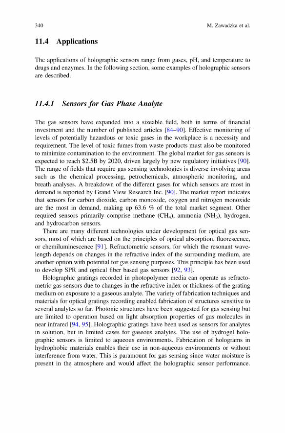
The exact contribution of each of the parameters can be estimated by modelingthe diffraction efficiency change:
Dgg
¼ 2tan pn0d
k cos h
� � pn0dk cos h
� �Dn0
n0þ Dd
d� Dk
kþ tan hDh
� �ð11:6Þ
Sensors based on transmission holographic gratings require both a light source forits illumination and a photodetector to monitor a diffraction efficiency alteration or avariation of the diffracted light direction. The main advantage of this type of sensorsis that small changes in order of 10−5 in diffraction efficiency can be detected.
11 Photonic Materials for Holographic Sensing 323

11.2.3 Holographic Recording by Ultra-Short Laser Pulses
Contrary to typical holographic recording protocols, particles can be organizedwithin a polymer matrix to produce a holographic grating using a high-energy fre-quency doubled Nd:YAG (Neodynium doped-Yttrium-Aluminum-Garnet) nano-second pulsed lasers or other high energy nanosecond lasers. The typical output forlaser ablation is 300 mJ with a 532 nm wavelength and a 258 s Q-switch delay. Highenergy laser radiation can reduce the size of metallic particles to nanometric scales byablation to smaller particles [16], thus affecting their optical properties [17–20]. InDenisyuk reflection mode for holographic recording by high-energy laser writing, thenodes of the standing waves provide concentrated energy to reorganize the preformedsilver nanoparticles, which are incorporated and formed in situ by perfusing silversalts [21]. In this setup, the laser beam is diverted using dichroic mirrors and lenses tostrike the recording material at desired angles [22]. An important parameter duringpatterning is the total laser energy that reaches the recording material. This energy istypically affected by the optics and can be modulated by changing the spot area ofincidence; larger patterning areas will have less energy striking the particles. For ahigh-energy laser, areas up to 2.5 cm in diameter can be used for effective recording[22]. Any material sensitive to absorption of the high laser energy can be used forholographic recording, typically silver nanoparticles (Ø = 50–100 nm) are used due tothe coincidence of their absorption spectrum due to their surface plasmon resonance
Analyteη = f( d1,n′1, 1,θ1 )
η = f( d2, n′2, 2, θ2)
d1
d2
Holographic sensor
Λ1
Λ2
θ1
2
1
θ
n′1
n′2
Fig. 11.5 The principle of operation of a holographic transmission grating sensor
324 M. Zawadzka et al.

(SPR) with that of green lasers [15, 21, 22]. The interaction between the laser lightand the matter in situ may influence matter diffusion, ejection, oxidation, structureand distribution. These effects can contribute to the reorganization of the matter in thepolymer matrix to form a grating. Since this fabrication approach is based on passingan absorption threshold to pattern thematerial, it may allow forming gratings for otherlow-cost and novel materials such as ink [23] to construct optical devices.Furthermore, this approach also opens the possibilities for patterning other materialssuch as graphene [24, 25], carbon nanotubes [26], and other nanostructures [27].
11.3 Holographic Sensing Materials
A holographic material suitable for sensing application must meet two mainrequirements: (1) it must enable holographic recording and (2) must be sensitive toa specific chemical or physical stimulus. This imposes specific requirements on thematerials that can be employed in holographic sensors, and different strategies havebeen adopted to functionalize the materials, and thus make them sensitive to aspecific stimulus. The simplest and the earliest explored approach to design ofholographic sensing materials exploits the intrinsic properties of materials used forholographic recording i.e. hygroscopic nature of gelatin was utilized to fabricatereflection-type holographic sensors for detecting water content in hydrocarbons[28]. Yet, to broaden the applications of the sensors and to improve their sensitivityand selectivity, further modifications of holographic materials were carried out.
11.3.1 Photonic Materials in Sensing Applications
Holographic sensing materials can be divided into three groups based on theirfabrication: (1) silver halides-based materials, (2) photopolymers, and (3) hybridmaterials. In the first group of materials, the holographic grating consists of periodicplanes of silver nanoparticles formed in a functionalized polymer matrix; sensitivityof the hologram to a specific stimulus arises from changes in the properties of thepolymer matrix functionalized with stimuli responsive moieties. In photopolymers,refractive index grating is formed as a result of localized photopolymerizationduring holographic recording; the polymer formed bears receptor units sensitive toa specific stimulus. The third group of sensing materials i.e. hybrid materials arephotopolymers modified with analyte sensitive nanoparticles such as zeolities,which can be redistributed in the photopolymer matrix during holographic recod-ing. The strategies used for the preparation of these three groups of materials arediscussed in the following sections.
11 Photonic Materials for Holographic Sensing 325

11.3.1.1 Silver Halide Chemistry
Silver halide chemistry is the earliest technique developed to fabricate holographicsensors. This approach is largely based on photography dating back to late 19thcentury, and the development of holography in the 1970s [29]. Traditional holo-gram emulsion contained a mixture of solidified gelatin doped with silver bromidenanocrystals (AgBr NCs) coupled with laser light-absorbing dye. In contrast to thetraditional emulsion, the fundamental fabrication difference in holographic sensorsis the development of a diffusion technique that allows impregnation of therecording media with silver halides after the formation of a polymer film [30].
The fabrication of a silver halide based holographic sensor consists of three mainsteps: (1) preparation of a functionalized polymer matrix that can consistentlyrespond to an analyte or physical parameter, (2) photosensitization of the polymermatrix, and (3) formation of diffraction gratings in the polymer matrix throughmultibeam interference of laser light and photographic processing [1]. Figure 11.6shows each step in fabricating holographic sensors through silver halide chemistry.The first step in the silver halide system is to prepare a functionalized polymer
Fig. 11.6 Formation of holographic sensors through silver halide chemistry. a Formation of a layerof silane on the glass slide. b UV-light initiated free radical polymerization of the monomers on theslide. c Rinsing the system with ethanol to remove the unreacted residues, and drying it under tepidair current. d Silver nitrate diffusion into the polymer matrix. e Drying the polymer under tepid aircurrent to fix the silver ions into the polymer matrix. f Immersing the polymer in a LiBr bath toobtain AgBr NCs in the polymer matrix. g Rinsing the system with deionized water and treatmentwith ascorbic acid to increase the sensitivity to laser light. h Laser light exposure in Denisyukreflection mode to form a multilayer diffraction grating in the polymer matrix. i Formation of silvernanoparticles in the recording medium using a photographic developer. j Stopping the developer’saction using acetic acid. k Hypoing the hologram using sodium thiosulfate. l Rinsing the systemwith ethanol solution to remove the residual dye in the hologram matrix
326 M. Zawadzka et al.

matrix, and impregnate the polymer matrix with silver ions [31, 32]. This step isneeded because forming an emulsion consisting of the functional monomers insolvents and aqueous silver halides is hindered due to their immiscibility. Hence,silver halides are introduced into the polymer matrix using so-called diffusiontechnique. Silver salts such as aqueous silver nitrate or silver perchlorate in organicsolvents (0.1–0.5 M) are diffused into a polymer matrix, which may be poly(2-hydroxyethyl methacrylate) pHEMA or poly(acrylamide) pAAm with a thick-ness of *10 to 20 µm. After the polymer matrix is dried under tepid air, thepolymer matrix is submerged into an aqueous solution consisting of LiBr (0.3 mM)and a photosensitizing dye (e.g., 1,1′-diethyl-2,2′-cyanine iodide) under safelighting. The reaction of LiBr with silver ions (Ag+) produces AgBr NCs withdiameters ranging from 10 to 30 nm [31]. The photosensitizing dye permanentlyattaches to surface of the AgBr NCs. After this step, the polymer matrix is rinsedwith deionized water. The polymer matrix maybe immersed in ascorbic acid toimprove the sensitivity to laser light. At this stage, the polymer matrix and AgBrNCs system is called recording medium.
Formation of a grating in the recording medium consists of laser writing of alatent image and photographic development of this image. The latent image is acollection of labeled AgBr NCs, which are subject to photographic development.The latent images are recorded in Denisyuk reflection mode, in which the recordingmedium is placed over a mirror with a tilt angle from the surface. Tilting the sampleallows offsetting the diffraction angle [33]. Under safe lighting, an expanded laserbeam is exposed onto the sample, where the incoming beam and the beam reflectedfrom the mirror forms a standing wave in the recording medium (Fig. 11.7). Thestanding wave forms a multilayer pattern running parallel to the surface of therecording medium. This pattern has a lattice spacing of approximately half of thewavelength of the laser light.
Under safe lighting, the recording medium with latent image is submerged in anaqueous photographic developer. This solution consists of a number of chemicals
Fig. 11.7 Formation ofholographic sensors inDenisyuk reflection mode
11 Photonic Materials for Holographic Sensing 327

that attack labeled AgBr NCs and reduce them to silver metal (Ag0) nanoparticles(NPs). A typical developer consists of 4-methylaminophenol sulfate (0.3 %, w/v),ascorbic acid (2 %, w/v), sodium carbonate (5 %, w/v), and sodium hydroxide(1.5 %, w/v) dissolved in deionized water [34]. Following the development of Ag0
NPs, the recording medium is submerged in acetic acid solution (5 %, v/v), whichallows stopping the action of the developer to prevent overdevelopment and dis-tortion in the recorded image. The diameter of resulting Ag0 NPs ranges from *10to 50 nm [35]. This process yields a diffraction grating consisting of periodic Ag0
NPs in the polymer matrix.The efficiency of the diffraction can be further improved by removing excess
AgBr. The post-development process consists of hypoing and bleaching the holo-gram. Sodium thiosulfate is the standard hypo solution that dissolves undevelopedAgBr NCs and improves the diffraction efficiency, which is otherwise reduced bythe interference of light with undeveloped AgBr NCs. The second step in thepost-development step is bleaching the hologram. Ag0 NPs are converted back toAgBr NCs, which yields improved diffraction efficiency due to the change in itsrefractive index that can transfer the incoming light to the next lattice spacing moreefficiently than Ag0 NPs.
The ability to produce holographic gratings with silver halide chemistry allows arange of diffraction gratings utilizing the traditional approaches. However, thenumber of fabrication steps is lengthy and tedious, and this process is incompatiblewith biological assays inhibiting enzymes [36]. Nevertheless, this image recordingtechnique remains a robust approach to fabricate holograms in hydrophilic poly-mers for aqueous applications.
11.3.1.2 Photopolymer Chemistry
Photopolymers are materials that change their optical properties in response toillumination with light. However, to be suitable for holographic recording, thephotopolymer must be capable of a localized response to the light, ideally capableof recording interference patterns of thousands of lines per millimeter, or features ofsub-micron dimensions. This allows the creation of a photonic structure within thepolymer that is capable of diffracting light, via the recording of the hologram in thematerial.
To be used in sensing applications, however, the photonic structure formed bythe above methods must also respond to the analyte so that characteristics of thehologram are altered. For volume holograms, layer permeability is also a key issue,because the analyte needs to diffuse through the polymer layer to cause a detectablechange in the hologram’s characteristics [1]. The polymer must also be sufficientlyrobust to maintain the photonic structure under exposure to the analyte’s envi-ronment and, in most applications, it must maintain this for multiple cycles of use.
This need to balance permeability with stability of the photonic structure nar-rows down the suitable sensing materials. Photopolymerizable systems using
328 M. Zawadzka et al.

acrylamide monomers and poly(vinyl alcohol) PVA have been shown to produceholograms that shift their reconstruction wavelength with complete reversibilitythrough many cycles of low and high humidity [37].
Such photopolymer layers are prepared by coating and drying a solution, whichis a mixture of monomers, sensitizers, and dissolved polymer on a suitable sub-strate. Because of the ease of preparation of the polymer films and the fact that theholograms are self-developing, fabrication of holographic sensors in such materialsis a straightforward two or three step process. First, the components of the pho-topolymer are mixed and coated on a substrate. The mixture usually consists of atleast two monomers, a photoinitiator, co-initiator and a polymeric binder such asPVA [38–45]. Heat is usually needed to dissolve the binder, but otherwise it is asimple mixing process. The photopolymer solution is then coated onto the glass orplastic substrate and allowed to dry for several hours on a level surface to form thephotosensitive layer as shown in Fig. 11.8a. The next step is to expose the pho-tosensitive layer to the appropriate interference pattern, at the appropriate laserwavelength to create the photonic structure. This is shown in Fig. 11.8b. Wherelight is absorbed by the layer (via the photoinitiator), a polymerization process isinitiated which converts the monomers into polymer and triggers local diffusionprocesses. The local refractive index is thereby altered through changes in the localdensity and polarizability of the molecules, and the spatial variation in intensity inthe interference pattern is recorded as a spatial variation of refractive index. Thehologram can be viewed immediately, but with some formulations a short
Photopolymer hologram
Substrate (glass or plastic)
Laser illumination
UV
Photopolymer coating solution
Substrate (glass or plastic)
Substrate (glass or plastic)
Hologram formed in polymer layer
Reflective surface (object or mirror)
(a)
(b)
(c)
Fig. 11.8 Formation of holographic sensors through photopolymer chemistry. a Drying thephotopolymer coating solution on the glass slide. b Laser light exposure in Denisyuk reflectionmode to form a volume diffraction grating/hologram in the polymer matrix. c UV-light fixing ofthe hologram
11 Photonic Materials for Holographic Sensing 329

additional step is advisable, exposure to white or UV light [46] to removeremaining sensitizer and stabilize the hologram (Fig. 11.8c).
The self-developing nature of the photopolymer materials means that the pho-tonic structure is fully formed during the exposure step and the hologram is visibleat that point. Denisyuk reflection hologram recording is one of many formats thatcan be used to form the hologram. The final appearance depends on whether areflective object or mirror was used to create the hologram, what wavelengths andangles were used in this step, and whether multiple recording beams were used. Formost holograms, a small tilt angle is introduced between the photosensitive layerand the mirror/object beam, typically between 5° and 10°. This prevents the beamdiffracted by the photonic structure from being obscured by the beam that isspecularly reflected from the layer surface.
The flexibility of this preparation process has allowed for a wide range ofcharacteristics in the final hologram. For example, by altering components of thebasic formulation, hard impermeable layers have been formed [47], new sensingproperties have been introduced [48] and new sensing strategies have beendeveloped in which the ability to form a hologram is the sensing action [49].Because of the role of diffusion in the recording process, it has also been possible topattern the dopant materials within the layer. This gives further scope for a tailoredsensing response. There is also significant flexibility around the wavelength used aslong as the appropriate initiator is chosen. Initiators sensitive to red, green and blueare available [50] which is useful in sensing applications where a particular initialcolor is desirable in the hologram. For example, if shrinkage rather than swelling isexpected, a hologram diffracting the longer, red wavelengths is likely to be adesirable starting point, but a blue diffraction might be a more suitable starting pointfor an analyte that swells the layer.
Photopolymer materials have a key role to play in holographic sensing becauseof the ease of preparation of the sensors, which facilitates their mass production.Further development is needed in ensuring specificity for certain analytes, and tofurther improve robustness in some environments, however the variety of formu-lations possible and the wide flexibility in the photonic structures that can beformed indicate the potential for these materials. One approach to the functional-ization of photopolymer materials is the incorporation of zeolite nanoparticles inthem. The following section describes the features of nanozeolites and their use inholographic sensing.
11.3.1.3 Sensors Containing Zeolite Nanoparticles
The synthetic zeolites, historically referred to as ‘molecular sieves’, are low-densitycrystalline aluminosilicates possessing regular micropores of dimensions com-mensurate with molecules (0.3–2.0 nm). These micropores (one-, two- andthree-dimensional) create a vast network of channels and cages with well-definedsizes and shapes. Other molecular sieves, the so-called zeotype materials, con-taining different tetrahedral (T = Si, Al, Ti, P, Ga, Ge, B) framework cations have
330 M. Zawadzka et al.

also been synthesized. Their corner-sharing tetrahedral building units (TO4) furtherextend the diversity of zeolite structures. This remarkable flexibility in structuretype (220 different structures known to date) and chemical composition allowstunable chemical and physical properties [51].
Over the past decade, much effort was devoted to prepare zeolites with enhancedaccessibility to their micropores. Many new routes to hierarchical zeolites havebeen revived and discovered, such as: (1) post synthesis modification byde-silication, de-alumination or steaming, (2) one-step hydrothermal crystallizationin the presence of specific organosilane surfactants acting as mesopore modifiers,and (3) synthesis of nanosized zeolite crystals with or without organic templates.The post-synthesis methods, such as steaming and chemical treatments are welldocumented and in commercial use, but they unavoidably lead to, inter alia, adecrease in zeolite crystallinity, the loss of a portion of the starting material, thecreation of many defects, inhomogeneous chemical compositions and a hithertouncontrolled broad distribution of mesopores, not always properly connected to themicroporosity.
The nanometer scale (<500 nm) zeolite crystals develop large external surfacewhere up to 30 % of their T atoms can be located and are intrinsically of betterquality than the crystals produced by an intrinsically destructive top-downapproach. A decrease in the size of zeolite crystals results in a considerableincrease of their external surface and the properties associated with the latter (ad-justable surface charge, hydrophilicity/hydrophobicity, ion-exchange) play anever-increasing role (Fig. 11.9). The surface properties provide new possibilities toexplore adsorption and reaction of bulky molecules that do not normally interactwith the micropore volume of the zeolites.
The zeolite nanoparticle research faces new challenges in their shaping in theform of membranes, films, self-supported bodies, since the interactions between thezeolite and its binder or support will involve the external surface of the zeolite.
Besides, the kinetics of adsorption and desorption are related to the particle sizeand therefore nanosized zeolites have the potential to increase substantially theproductivity of existing processes or to drastically reduce the size of new devices.
Fig. 11.9 Properties of nanosized zeolites
11 Photonic Materials for Holographic Sensing 331

Nanosized zeolites are usually synthesized at low temperature underhydrothermal conditions. The initial system is usually an aluminosilicate suspen-sion that evolves under the combined action of mineralizing (OH−, F−) andstructure-directing agents (SDAs). The SDAs could be alkali metal cations orpositively charged organic molecules. The generally accepted scheme includes thearrangement of SiO4- and AlO4-tetrahedra around charged templating species, i.e.hydrated alkali metal cations or organic molecules. The synthesis of nanosizedzeolites is strongly influenced by the: (1) organic additives or structure-directingagents, (2) type of precursor synthesis gel/suspension, (3) initial silicon and alu-minium source, (4) synthesis conditions as temperature, pressure and time, and(5) heating method like conventional, microwave and sonication. A dedicated effortto understand the fundamentals of the above-mentioned parameters generatedvaluable knowledge to direct the synthesis and harvest zeolite nanocrystals withpre-determined properties [52–54].
The nanosized zeolites have high quality crystals with diverse sizes and mor-phology that are important for fundamental studies and advanced applications(Fig. 11.10). In addition the crystals can be modified via post-synthesis treatmentthat changes the surface and bulk properties and lead to high selectivity and alsoallows fast diffusion (Fig. 11.11).
New fields will also open up to due to their exceptional properties and becausethey can be supplied in various forms, such as colloidal suspensions, optical qualitythin films, membranes and self-supported morphologies (Fig. 11.12).
A large research effort is dedicated to the use of zeolite nanocrystals to preparethin-to-thick zeolite layers for optical devices and gas/liquid sensors. The commonpreparation techniques of such devices include: (1) screen-printing, (2) sol-geltechniques, (3) dip- and spin-coatings, (4) direct growth with or without pre-seedingof the substrates, and (5) ink-jet printing. Factors to consider when selecting theproduction technique include the required film characteristics, purity, porosity,reliability, reproducibility and costs. Zeolite films are used for preparation of opticalquality films with a thickness in the range 50–170 nm through spin-on or sol-geldeposition methods [55, 56].
Fig. 11.10 Highly porous zeolite nanoparticles exhibiting different shape and size
332 M. Zawadzka et al.

The large and reactive external surface of the zeolite nanocrystals is critical todesign different morphological constructions, where the consequence processingdoes not affect the intrinsic properties of nanocrystals. The supported zeolite films
Fig. 11.11 Nanosized zeolite crystals: high selectivity, short diffusion path, surface and bulkmodification
Fig. 11.12 Nanosized zeolites in colloidal suspensions and shaped in films, membranes andself-supported bodies
11 Photonic Materials for Holographic Sensing 333

are used for separation, membrane, optical devices, chemical sensors and medicalapplications.
The versatility of zeolites properties like their pore structure, surface area, cat-alytic activity, particle size and morphology is of particular interest for differenttypes of sensors. Their adsorption capacity, high-surface area and porosity, pres-ence of mobile ions, and catalytic activity make them attractive candidates forchemical sensing/detection. In general the sensors are categorized in four groupsbased primarily on their mode of action: (1) chromatography and spectrometry,(2) electrochemical sensors, (3) mass sensors, and (4) optical sensors. Zeolite-basedchemical sensors are divided in two groups depending on the respective role of themolecular sieves. The zeolite can act as the main functional element, in the case ofsensors based on conductive, adsorptive, or catalytic properties of one specific typemolecular sieve and its interaction with the analytes. The second group includesdevices where the zeolites are supplementary or secondary elements, e.g. host-guestmaterials with active sites encapsulated within the zeolite pores.
The application of nanosized zeolites in chemical sensing, biomedical andbiological analyses has shown their great potential [57–62]. Zeolite nanocrystalsoffer promises in the above applications due to their highly tuneable size- andshape-dependent chemical and physical properties. Their unique surface chemistry,high thermal stability, high surface area and large micropore volume are importantfor designing of optical devices. Useful strategies for functionalization of zeolitenanoparticles open up the possibility of using the materials in areas such as envi-ronmental drug delivery, medical imaging and other biomedical applications.
An example of the potential of zeolite nanoparticles in sensing is their use infunctionalizing photopolymer materials for holographic sensors. The incorporationof these nanoparticles into a holographic photopolymer medium can improve itsdynamic range, and thus its ability to record high diffraction efficiency holograms[63]. This improvement is ascribed to the redistribution of the nanoparticles duringholographic recording. The nanoparticles are redistributed within the photopolymermaterial into either the bright or dark fringe regions [64, 65]. For example zeolitenanoparticles incorporated in an acrylamide-based photopolymer are redistributedinto the dark fringe regions during holographic recording (Fig. 11.13a) [66]. Thetotal refractive index modulation n′ created during recording (Fig. 11.13b) has twocomponents: (1) photopolymerization and diffusion driven density variation of thepolymer material and (2) the zeolite nanoparticle redistribution. The contribution ofthe zeolite nanoparticles to the refractive index modulation n0n can be expressed as:
n0n ¼2fnanoparticle
pðnnanoparticle � nhostÞ sinðapÞ; ð11:7Þ
where nnanoparticle and nhost are the refractive indexes of the nanoparticles and thehost polymer matrix and fnanoparticles is the volume fraction of the redistributednanoparticles, α a is the fraction of the period spacing with a high-concentration ofnanoparticles.
334 M. Zawadzka et al.

Upon exposure to an analyte, the target molecules are adsorbed to thenanoparticles, causing nnanoparticle to increase, and change nn′. This thereforechanges the overall refractive index modulation n′. If the nanoparticles are pref-erentially distributed in the dark fringes, the exposure to the target analyteFig. 11.13c decreases the overall refractive index modulation Fig. 11.13d. Asshown in (11.5), the intensity of the light diffracted by the grating is directly relatedto the refractive index modulation n′. Therefore, by monitoring changes in thediffracted beam intensity during exposure to an analyte, holographic gratingsrecorded in the nanoparticle-doped photopolymer can be used as a sensing device.By selecting nanoparticles with a porous structure e.g. zeolite nanoparticles,adsorption of the target molecules to the nanoparticles can be maximized, thusmaximizing the sensor’s sensitivity. By controlling zeolite pore size or by incor-porating functionalized nanoparticles (e.g. having metal ions/nanoparticles in thezeolite pores) [60], an improved selectivity of the holographic sensing device to thetarget analyte can be achieved.
11.3.2 Strategies for Materials Functionalization
Holographic sensors can be classified with regard to their fabrication process assilver halide based materials, photopolymers or nanoparticle doped materials, whichwere discussed in the previous sections. Depending on the mechanism of operation,
Fig. 11.13 Schematic showing the redistribution of nanoparticles within the holographic gratingand the effect of analyte molecules on Δn of the grating before (a, b) and after exposure to theanalyte (c, d)
11 Photonic Materials for Holographic Sensing 335

another classification of holographic sensors can be adopted: (1) structures withpatterned analyte sensitive species; in such structures, interaction of the analyte withthe patterned holographic structure changes the refractive index modulation; suchstructures can operate both in transmission or reflection holographic sensors (2) inthe second type of structures, no spatial redistribution of stimuli responsive func-tionalities is needed; such structures work best in reflection mode; the interaction ofsuch sensors with the stimuli results in changes in Bragg peak and thus color of thereconstructed holographic image.
11.3.2.1 Structures with Redistributed Analyte-Sensitive Species
To produce such structures, the analyte-sensitive species must be able to diffusewithin the material during holographic recording to produce analyte receptor-reachand receptor-depleted regions. This approach was applied to nanozeolite dopedphotopolymers [60, 67, 68]. Extensive research into acrylamide-based photopolymernanocomposites containing three different zeolite nanoparticles with varyingmicroporosity, namely Silicalite-1 (MFI-structure, Ø = 30 nm), AlPO-18(AEI-structure, Ø = 180 nm) and Beta (BEA-structure, Ø = 40 nm) has beenreported [63, 68–70]. Preliminary studies into the sensing ability of transmissiongratings recorded in BEA- and MFI-type zeolite-doped acrylamide photopolymerlayers have been reported for the analytes such as toluene [67] and isopropanol [60].
11.3.2.2 Structures with No Redistribution of the Analyte SensitiveSpecies
The simplest examples of such structures exploit intrinsic properties of holographicrecording media, and the earliest research in the holographic sensors area reliesupon such structures. Hygroscopic properties of gelatin were employed in theearliest holographic sensors that were capable of detecting water content inhydrocarbon solvents [28]. The recorded grating acts as a readout system and is notinvolved in sensing. More advanced sensors within this category comprise varioushydrogels containing appropriate receptor groups. Polymer matrices can be func-tionalized with a range of monomers that allow in sensing analytes specifically. Thefunctionalization can be achieved before or after polymer formation. A criterion inselecting these functional groups is that they should have acrylate or methacrylategroups that allow covalent crosslinking in the polymer matrix. This strategy wasused for pAAm and pHEMA hydrogels to obtain sensors sensitive to pH [31, 32,71–73], ions [73–77], glucose [73, 78–80], temperature [37, 81] and other stimuli[1]. For example, copolymerization of a hydrogel with the monomers bearing acidicor basic groups, along with the suitable crosslinkers, enabled the fabrication ofsensors with tunable pH response [32]. Ionization of the functional groups in pHsensors swells the grating due to electrostatic and osmotic forces which draws orexpels counterions and water into or out of the hydrogel matrix.
336 M. Zawadzka et al.

Over the last two decades, a range of functional groups has been utilized insensing chemical species (Fig. 11.14). These include carboxylic acid, crown ethers,8-hydroxyquinoline, porphyrin and phenyl boronic acid derivatives. The sensingproperties of these functionalities are well known in other types of sensors.Structures with no redistributed sensing species were also applied for zeolitenanoparticles based sensors to obtain structures sensitive to toluene [67]. Furtherdescription of holographic materials bearing these functionalities can be found inSect. 11.4 in regard to their applications.
11.3.2.3 Functionalization Strategies Based on the Hydrophobicityand Hydrophilicity of the Recording Material
Holographic sensors can also be classified by the type of fabrication materials andtheir properties, for example, there are holographic sensors fabricated in hydrophilicmaterials for sensing in aqueous solutions, and there are holographic sensors fab-ricated in hydrophobic materials for non-aqueous applications. The polymers usedin holographic sensor fabrication determine not only the nature and type of analyte,but also the recording technique of the holographic layers. Hybrid materials can beconceived for the integration of multianalyte holographic sensing by havinghydrophobic and hydrophilic domains. These domains can include nanoparticles asin traditional holography and enhance the holographic sensitivity and refractiveindex contrast, also useful for high laser energy patterning. These materials can beselected from block copolymers or hybrids with nanoparticles with enhancedoptical contrast [82]. In sensing mechanisms, changes in Λ for example can beoriginated by expansion or contraction of the polymer matrix material. Thisexpansion and contraction is caused by the chemical interactions with the analytes.The fringes are made of refractive index varying material and could also be made ofmetallic particles that do not swell or contract. However, changes in refractive indexcan be triggered by physicochemical modifications of the fringes or the polymermatrix. For instance, metallic nanoparticles can undergo chemical transformationsthat modulate their refractive index upon reduction or oxidation with chemicalanalytes [83].
Fig. 11.14 Functionalization of holographic sensors with various monomer groups
11 Photonic Materials for Holographic Sensing 337

11.3.3 Design of Sensors by Dynamic Simulationsof the Properties of a Multilayer Structure
Rational design of holographic sensing materials can be facilitated by computersimulations. It has been demonstrated that the principle of sensing of a multilayerstructure can be modeled by finite element analysis. For example [31],finite-element simulations of the multilayer structured allowed analyzing the wavepropagation and optical response in holographic sensors [71, 78]. There are otheranalytical methods that predict the reflectivity of light in periodic structures thatwork for arbitrary periodic dielectric structures and can be applied to the particularcase of one dimensional photonic devices such as holograms. These methods can beexact solutions to the Maxwell equations or approximations by matrix formalisms.The simulated model comprised a cross-section of several stacks of silvernanoparticles with a mean radius of 13 ± 10 nm (Fig. 11.15a). Within each stack theparticles were uniformly distributed in the vertical direction, while in horizontaldirection, normal random distribution was used. The spacing (vertical lattice con-stant) between stacks was initially set to 188 nm. The model was used to simulatethe wave propagation through the lattice for the wavelength range of 400–1000 nm.Simulations were performed to analyze the effect of expanding the holographicsensor on the reflection band gaps. Figure 11.15d shows that the multilayerstructure displayed a reflection band gap centered at a wavelength of *500 nm (theleast transmitted). This is equivalent to the optical response displayed by theholographic sensors at a pH of 4.00 [71]. To simulate the dynamic tunability,the multilayer structure was expanded while keeping the number and dimensions ofthe nanoparticles the same. As shown in Fig. 11.15a–c, the expansion increased theeffective-stack spacing, and stack size, however reduced the concentration ofnanoparticles per stack. The reflection spectra showed a red shift in the reflectionbands as the stack spacing was increased (Fig. 11.15d). The expanding multilayerstructure displayed a color change varying across the visible spectrum from *500to 815 nm. With an increase in stack spacing, the efficiency of the multilayerstructure decreased, shown by the decrease in the intensity of the reflectiondip. This was due to the decrease in the concentration of nanoparticles present ineach stack, which reduced the effective index contrast between the nanoparticlestacks and medium.
To further test this hypothesis, additional simulations were performed withvarying number of particles per stack. Figure 11.15e illustrates the simulatedreflection spectra for the two geometries with same lattice spacing but differentnumber of nanoparticles per layer. Decreasing the number of nanoparticles from 60to 30 decreased the effective refractive index of the stacks, and therefore this trendreduced the index contrast between stacks and the hydrogel. This led to a weakerreflection dip, which could be observed from the simulated reflection spectra(Fig. 11.15e). The multilayer structure with 30 particles per stack displayed about55 % weaker band gap and reflected less light. The position of the reflection banddid not change as the effective lattice constant remained unchanged.
338 M. Zawadzka et al.

Even though the efforts to simulate the photonic properties given the appropriatematerial result in full understanding on the light propagation, the selection of thematerials remains empirical and work on the incorporation of physicochemicalmodels and photonic models is still required. Furthermore, on the coupling suchmodels with those of inter-molecular interactions between the sensor materials andanalytes, models for practical application can be created.
Fig. 11.15 Simulated opticaltransmission spectra for thenanoparticle stack basedholographic sensors [31]. a–c Modeled geometries of ahorizontally expandingmultilayer structure consistingof silver nanoparticlesdispersed within a hydrogelmatrix. d The simulatedtransmission spectra formultilayer structure withfringe spacing expandingfrom 188 to 306 nm.e Simulated spectra andmodeled geometries of aholographic sensor with alattice constant of 200 nmcontaining 60 and30 nanoparticles per fringe
11 Photonic Materials for Holographic Sensing 339
11.4 Applications
The applications of holographic sensors range from gases, pH, and temperature todrugs and enzymes. In the following section, some examples of holographic sensorsare described.
11.4.1 Sensors for Gas Phase Analyte
The gas sensors have expanded into a sizeable field, both in terms of financialinvestment and the number of published articles [84–90]. Effective monitoring oflevels of potentially hazardous or toxic gases in the workplace is a necessity andrequirement. The level of toxic fumes from waste products must also be monitoredto minimize contamination to the environment. The global market for gas sensors isexpected to reach $2.5B by 2020, driven largely by new regulatory initiatives [90].The range of fields that require gas sensing technologies is diverse involving areassuch as the chemical processing, petrochemicals, atmospheric monitoring, andbreath analyses. A breakdown of the different gases for which sensors are most indemand is reported by Grand View Research Inc. [90]. The market report indicatesthat sensors for carbon dioxide, carbon monoxide, oxygen and nitrogen monoxideare the most in demand, making up 63.6 % of the total market segment. Otherrequired sensors primarily comprise methane (CH4), ammonia (NH3), hydrogen,and hydrocarbon sensors.
There are many different technologies under development for optical gas sen-sors, most of which are based on the principles of optical absorption, fluorescence,or chemiluminescence [91]. Refractometric sensors, for which the resonant wave-length depends on changes in the refractive index of the surrounding medium, areanother option with potential for gas sensing purposes. This principle has been usedto develop SPR and optical fiber based gas sensors [92, 93].
Holographic gratings recorded in photopolymer media can operate as refracto-metric gas sensors due to changes in the refractive index or thickness of the gratingmedium on exposure to a gaseous analyte. The variety of fabrication techniques andmaterials for optical gratings recording enabled fabrication of structures sensitive toseveral analytes so far. Photonic structures have been suggested for gas sensing butare limited to operation based on light absorption properties of gas molecules innear infrared [94, 95]. Holographic gratings have been used as sensors for analytesin solution, but in limited cases for gaseous analytes. The use of hydrogel holo-graphic sensors is limited to aqueous environments. Fabrication of holograms inhydrophobic materials enables their use in non-aqueous environments or withoutinterference from water. This is paramount for gas sensing since water moisture ispresent in the atmosphere and would affect the holographic sensor performance.
340 M. Zawadzka et al.
Additionally, electronics accompanying the sensor devices are a hurdle whenremote access or monitoring is required; holograms on the contrary can usediffraction gratings as a transducer of the signal [96].
11.4.1.1 O2, N2, Alkanes, Alkenes, Alkynes, and NH3
Oxygen is traditionally measured by redox reactions on electrode surfaces thatconsume it in the process, and other methods use fluorescence quenching. Theseprocesses are limited by the availability of materials or the oxygen consumption.The irreversibility of the sensing process imposes a limitation, and the reversibilitycan yield weak interactions and a complex readout signal. This is similar forhydrocarbon gases alkanes, alkenes and alkynes, and volatile organic compounds(VOCs). Current technologies for real time sensing of hydrocarbon gases andVOCs [97] are not able to distinguish molecular differences or get high signals.Ammonia, as oxygen, is measured with potentiometric techniques that consume orsolubilize the analyte; others include absorbent semiconductors, which also con-sume the analyte or themselves [98]. Ammonia sensors are easily exhausted,requiring sensor’s replacement after measuring large quantities of ammonia; fur-thermore, typical ammonia sensors cannot measure high concentrations of ammoniaand exhibit a detection limit of 100 ppm [99]. Therefore, these sensors are notsuitable for high analytes concentration environments, where special protection andrapid continuous monitoring is required. Holographic gas sensors provide a solutionto these hurdles since they are able to measure such gases reversibly.
Hydrocarbons and VOCs have aliphatic chains that can hydrophobically interactvia Van der Waals’ forces. Hydrophobic interactions are sufficient to trigger sensingaction in holographic sensors, and are reversible. The design of holographic sensorsfor VOCs and hydrocarbons is based on these mechanisms. The recognitioncomponent of the sensor should have reversible hydrophobic interactions withgaseous analytes. This material not only must be compatible with the analyte butalso comply with holographic recording. In other words, the material should behydrophobic, optically transparent and light sensitive for recording the laser lightwavefronts. Ultrashort laser pulse patterning by ablation has been used in poly-styrene and polypropylene, and also more successfully with poly(dimethylsiloxane)(PDMS) [15, 21]. VOCs are inert to silver particles, and there is no evidence ofchemical reactions between the silver particles and hydrocarbons, that change theirrefractive index. Therefore, hydrocarbons and VOCs swell the holographic sensormatrix. A plethora of VOCs can be distinguished: branched and unbranchedalcohols, polyols, molecules with carbonyl groups. High molecular weight ketones,alcohols and hydrocarbons in the liquid state such as n-pentane, 1-pentene,1-pentyne, hexane, heptane, octane, decane, 4-methyl-2-pentanone, heptanone,hexanol, heptanol, iso-amyl alcohol and tert-amyl alcohol can be detected byholographic gas sensors. Since hydrophobic interactions swell PDMS chains, sur-face electrostatic potentials are the cause of the holographic response.
11 Photonic Materials for Holographic Sensing 341

Oxygen and ammonia can form weak dipoles upon interaction with othermolecules or species and are able to form reversible covalent bonds due to partialcharges in their molecular structure [98, 100]. Thus, a holographic sensor aiming todetect these gases should exploit the nature of their molecular interactions.A drawback is the high reactivity of these gases. The holographic sensor responsecan also be affected by refractive index in combination to swelling, hence, a sensormaterial for oxygen and ammonia should selectively accept charged or partiallycharged molecules and generate molecular changes that affect either refractiveindex or swelling. For example, ion-exchange membranes are transparent, andselectively interact with charged or partially charged molecules and are thereforeideal candidates for the construction of holographic oxygen and ammonia sensors.Polar hydrophilic interactions with sulphonate groups in Nafion cause changes inthe position of the Bragg peak and intensity in reflection-type holographic sensors.Physical phenomena such as absorption, diffusion, swelling, and ionic dissociationmay affect the sensing process [101].
11.4.1.2 Zeolite Nanoparticle Doped Sensors for the Detectionof Alcohols
As described in Sect. 11.3.1.3, zeolite nanoparticles are an attractive option for thefunctionalization of photopolymer-based sensors. They are particularly promisingfor developing gas sensors due to their porosity, which allows for increasedadsorption of gas molecules and selectivity.
The diacetone-acrylamide-based photopolymer doped with BEA type zeolitenanoparticles shows improvement in refractive index modulation as a result ofholographic recording in this material [102]. This behavior has been ascribed to theredistribution of the zeolite nanoparticles. The zeolite pores remain empty due tothe larger size of the monomer molecules than the nanoparticle pore sizes [102].Therefore, gas molecules can be adsorbed inside the BEA zeolite pores (dependingon the gas molecule size) as well as to the zeolite surface, potentially maximizingthe gas molecules’ effect on the refractive index modulation change. The synthesisof the BEA zeolites is described in literature [63]. The BEA zeolites are hydro-philic, which ensures they are compatible with the water-soluble diacetone acry-lamide (DA) photopolymer. In addition, the DA monomer demonstrates reducedtoxicity in comparison to the acrylamide (AA) monomer, which is advantageous toreduce occupational and environmental hazards of any sensor.
For this study, alcohol gases were selected as the main test analyte. Thedetection of alcohol in its gaseous form allows for in situ, real-time measurementsto be carried out. The sensing ability of gratings recorded in the photopolymerdoped with zeolites (0–2 %, w/w) was investigated for three different alcohols:methanol, isopropanol, and 2-methylpropan-2-ol. These three alcohol moleculeswere selected due to their differing molecular structures and physical properties(Table 11.2). The adsorption of the gas molecules within the holographic gratingdepends on the molecular size and structure of the adsorbing molecule (Table 11.2).
342 M. Zawadzka et al.

The diffracted intensity was monitored in real time as a function of gas exposureduration at 16 torr to allow for comparison of the different gases tested. Gratingswere recorded in 38 ± 3 µm thick photopolymer layers at a spatial frequency of1000 ± 30 l/mm with a recording wavelength of 532 nm.
For undoped gratings, there was a limited effect on the diffraction efficiency ofthe hologram at low gas pressure (16 torr) for all three alcohol gases (Fig. 11.16a).For 2-methylpropan-2-ol, the largest change was observed with the normalizedintensity decreasing by 5 %.
For the 2 wt% doped gratings, there was a more significant change in normalizeddiffraction intensity on exposure to the three gases (Fig. 11.16b). For isopropanoland 2-methylpropan-2-ol, normalized intensity decreased by 5 and 8 %, respec-tively. For methanol, the intensity initially decreased by 5 % after 3 min ofexposure; however, the intensity then began to increase, eventually exceeding theinitially intensity by 2 %.
The same trend of decreasing diffracted beam intensity with increasing exposuretime was observed for both the isopropanol and 2-methylpropan-2-ol gases in thezeolite-doped gratings. For both gases, only a limited effect on diffraction efficiency ofthe undoped grating was observed. The data matches the predicted effect of the gas onthe zeolite-doped grating; gas molecules are adsorbed to the porous zeolitenanoparticles causing the refractive index of the regions containing the redistributednanoparticles to increase, therefore decreasing the overall refractive index modula-tion. In the case ofmethanol, the smallest gasmolecule tested, the normalized intensitybegan to increase after 3 min of gas exposure for the 2 wt% zeolite-doped samples.
Table 11.2 Physical properties of methanol, isopropanol, and 2-methylpropan-2-ol [103]
Molecular weight(g/mol)
Refractive index[103]
Relative polarity(RP)
Methanol (CH4O) 32.0 1.329 0.762
Isopropanol (C3H8O) 60.1 1.377 0.546
2-Methylpropan-2-ol(C4H10O)
74.1 1.387 0.389
Fig. 11.16 Normalized intensity versus exposure time (s) for a (a) 0 and (b) 2 wt% zeolite-dopedgrating exposed to methanol, isopropanol and 2-methlypropan-2-ol at a gas pressure of 16 torr [104]
11 Photonic Materials for Holographic Sensing 343

This is the opposite of the trend observed for isopropanol and2-methylpropan-2-ol. Adsorption of the gas molecules to the zeolites redistributedwithin the grating increases their refractive index, and have the opposite effect onn1, therefore another process may occur simultaneously independent of the zeolitenanoparticles. One possible explanation is that the small size combined with thehigh polarity of the methanol molecule allows it to freely enter the pores of thepermeable polymer and swells the photopolymer layer doped with zeolite crystals.A more polar molecule such as methanol (RP = 0.762) is more reactive in com-parison to isopropanol (RP = 0.546) and 2-methylpropan-2-ol (RP = 0.389), andthus higher swelling of the layer is expected in the presence of methanol.
For all three gases, the effect of the gas molecules on the holographic gratingswas fully reversible. This implies that the gas molecules can readily enter and exitthe polymer matrix as well as the zeolites.
11.4.1.3 Humidity Sensors
Humidity can be detected by a number of techniques varying from the simplestmethod exploited the contraction/expansion of human hair to the advanced tech-niques used electronic chips. Crucial parameters of a humidity sensor are itsaccuracy, operating relative humidity (RH) range, response time, reversibility,compactness and weight, cost, ease of operation, and maintenance. Holographicsensors are capable of providing fast, real-time, reversible or irreversible, visualcolorimetric or optical readouts. Moreover, remote monitoring and multiplexing ofdifferent sensors are possible. Additionally, they are lightweight, small, and rela-tively low cost. Thus, holographic sensors can be used for the fabrication of dis-posable devices.
Holograms with the capacity to respond to humidity with easily identifiablechange in their optical properties, accompanied by resistance to damage by theenvironment, are of particular interest in humidity sensor development. Theapplication of photopolymers for the development of humidity holographic sensorsis under active study [47, 48, 105, 106]. Humidity response of reflection hologramsrecorded in a self-processing acrylamide-based photopolymer [39] has beendemonstrated in the range of 5–80 % RH [81, 105]. Reversible changes in fringespacing due to water vapor absorption causes fully reversible changes in the colorof the light diffracted by the reflection grating. The mechanical capacity of thephotopolymer layer to swell or shrink at different levels of relative humidity wasused for the development of holographic humidity indicator.
Photopolymers are suitable for the development of sensors as its sensitivity tohumidity can be altered by varying the photopolymer composition. The firstapproach is to use different photoinitiators. Photopolymer layers containing tri-ethanolamine are permeable to water vapor, and as a result the properties ofphotopolymer-based holographic gratings are humidity-dependent. However, pho-topolymer layers containing N-phenylglycine are robust and non-sensitive tohumidity up to RH = 70 %.
344 M. Zawadzka et al.

Recently, it has been shown that humidity response of transmission gratingsrecorded in an acrylamide-based photopolymer containing triethanolamine could beutilized for the development of irreversible holographic humidity sensors [106].Both diffraction efficiency change and shift in the Bragg peak were observed afterexposure to RH = 90 %. Reversibility of the observed changes in properties ofgratings was dependent on ambient temperature (T); specifically changes wereirreversible at T > 16 °C, and fully reversible at lower temperatures.
The substitution of triethanolamine by N-phenylglycine allowed the develop-ment of a humidity-resistant acrylamide-based photopolymer [43]. No response tohumidity changes was observed at RH = 20–70 % [47]. Moreover, fully reversibledecrease in normalized diffraction efficiency defined as the ratio of diffractionefficiency at given humidity level and the diffraction efficiency measured at the startof the experiment at RH = 20 % was detected at RH = 80–90 %. This photopolymercan be applied where non-sensitive humidity material is needed. For example,humidity-resistant material is beneficial for the development of holographic sensorswhen the response to environmental changes should be minimized. Thereby,humidity-resistant acrylamide-based photopolymer can be utilized as a basiccomposition for the development of novel sensors with introduced response to otheranalytes, accompanied by resistance to humidity.
The second approach to the design of humidity sensitive photopolymers is to usedifferent monomers. A non-toxic and environmentally-compatible photopolymermaterial [107, 108] is an alternative to acrylamide-based photopolymers for manyholographic applications including holographic humidity sensors. In this pho-topolymer formulation, low-toxic DA is used as the main monomer.
Humidity response of slanted transmission gratings recorded in DA-basedphotopolymer layers with the thickness of 60 μm was investigated in the range of20–90 % RH [48]. In this study, a two-beam holographic optical setup was utilizedto record slanted transmission gratings with a slant angle of 13° and a spatialfrequency of 1250 l/mm using a Nd:YVO4 laser (532 nm). Figure 11.17 shows therelative change in the diffraction efficiency of gratings recorded in DA-based andAA-based photopolymers as compared to relative humidity. Relative change in thediffraction efficiency was calculated as follow. The difference of the diffractionefficiency measured at certain relative humidity and the diffraction efficiencymeasured at RH = 20 % was normalized to the diffraction efficiency at RH = 20 %.The humidity response of DA-sample was significant (Fig. 11.17). Thus, even atlow relative humidity of 20–40 % (Fig. 11.17), there was a 50 % increase in thediffraction efficiency of DA-sample, whereas the diffraction efficiency ofAA-sample was increased by few percent. Reversibility of the observed changeswas confirmed at RH < 80 %. Thus, due to substantial humidity sensitivity ofDA-based photopolymer, this photopolymer can be utilized for the development ofa reversible sensor for continuous humidity monitoring in the relative humidityrange from 20 to 70 %.
11 Photonic Materials for Holographic Sensing 345

11.4.2 Temperature Sensors
Among the large variety of non-electrical temperature sensors, holographic tem-perature sensors can be classified as the sub-category of thermal indicators andthermometers based on thermal expansion. Firstly, the operation of holographictemperature sensors is based on thermal expansion/contraction of the polymermatrix. Secondly, temperature changes the reflectivity/transmittance of the holo-graphic grating or the wavelength of the refracted light. When a holographic sensoris based on a reflection holographic grating, it works as a thermal visual indicator.
Most of the photopolymers including acrylamide-based photopolymers have lowglass transition temperatures. In these materials, temperature exposure is known toinduce grating detuning effects originating from changes in the refractive index andthe dimensions of the photopolymer layers [109]. Thus, the ability of photopoly-mers to expand under temperature can be implemented for the development ofholographic temperature sensors.
The temperature response of reflection holograms recorded in anacrylamide-based photopolymer was investigated in the range of 15–50 °C [37, 81].The shift of the spectral peak wavelength highly depended on the relative humiditylevel so that it is negligible below 30 % of relative humidity, and is 25 nm at 45 %of relative humidity. Recently, investigation of the temperature response of slantedtransmission gratings with a slant angle of 13° recorded in photopolymers wascarried out by the characterization of Bragg angle shift at different temperatures[48]. Three types of photopolymers containing different monomers and photoini-tiating systems were used as recording media. The first type, photopolymer A, wasan acrylamide-based photopolymer containing triethanolamine as the electrondonor [39]. The second type, photopolymer B, was a derivative of theacrylamide-based photopolymer that uses N-phenylglycine as the electron donor[43]. The third type, photopolymer C, was a diacetone acrylamide-based pho-topolymer containing triethanolamine [108].
20 30 40 50 60 70 80 90
0
3
6
9
12
15
20 30 40
0.0
0.2
0.4
0.6
Δη/η
20
Relative humidity, %Δη
/η20
Relative humidity, %
Fig. 11.17 Relative changesof the diffraction efficiency ofslanted transmission gratingsrecorded in DA-based (bullet)and AA-based (triangle)photopolymers at differentlevels of relative humidity[48]
346 M. Zawadzka et al.

Figure 11.18 presents the Bragg angle shift of slanted transmission gratingsrecorded in photopolymers with different composition in the range of 20–60 °C.According to the recording geometry, if Bragg angle shifts to a bigger value theshrinkage of the layer is expected.
In the case of photopolymers containing triethanolamine (photopolymer A andC) exposure to temperature shrinks the layers leading to a significant Bragg angleshift, whereas photopolymer B containing N-phenylglycine exhibits a low responseto temperature changes (Fig. 11.18). Analysis of the three materials by differentialscanning calorimetry showed that the behavior of the Bragg angle shift for differentphotopolymers can be explained by different ability of photopolymers to releasewater due to temperature increase [48].
Photopolymer C is a humidity-sensitive material suitable for sensor development[48]. To analyze the thermal effect on properties of holographic gratings recorded inphotopolymer C, the temperature response of sealed layers was investigated.Figure 11.19 shows that the behaviors of the Bragg angle shift of sealed andunsealed samples are fully opposite, i.e. exposure to temperature swells the sealed
Fig. 11.18 Temperature dependence of the Bragg angle shift in photopolymer A (filled square),photopolymer B (filled triangle) and photopolymer C (open circle) [48]
0.8
0
0.8
1.6
2.4
20 30 40 50 60
Bra
gg a
ngle
shi
ft, d
egre
e
Temperature, C
unsealed
sealed
swel
ling
shrin
kage
Fig. 11.19 Temperaturedependence of the Braggangle shift in photopolymer C[48]
11 Photonic Materials for Holographic Sensing 347

layer and shrinks the unsealed layer. Swelling of the sealed layer can be explainedby relatively large thermal expansion of photopolymer C inherent to polymermaterials with low glass transition temperature.
The results demonstrate an effective approach to obtain photopolymer-basedgratings with tunable temperature sensitivity. Thus, photopolymers containing tri-ethanolamine can be exploited as a thermo-responsive materials for the develop-ment of holographic temperature sensors.
11.4.3 Pressure Sensors
Sensors are widely used for controlling and monitoring of pressure. The sectorsrequiring pressure sensing devices include the petrochemicals, automotive, dentaland medical industries. The market size of pressure sensors in 2011 was $5.11 Band is expected to reach $7.34 B by 2017 [110].
Photopolymers are an attractive option for pressure-sensing applications due totheir elasticity and compressibility. Reflection gratings recorded in photopolymerformulations have been shown to work as effective relative humidity sensors due totheir ability to swell and shrink as the humidity of the surrounding environment ischanged [111]. The same principle of operation can be applied to aphotopolymer-based holographic pressure or stencil stretch sensor [111–115](Fig. 11.20). A reflection hologram was recorded in an elastic photopolymermaterial which compressed under pressure, reducing the hologram thickness andtherefore the fringe spacing [5]. This reduction in fringe spacing corresponds to adecrease in the diffraction wavelength at which the hologram reconstructs.Assuming the hologram has high enough diffraction efficiency, this change may bevisible to an observer, as well as quantifiable with a spectrometer.
Fig. 11.20 Principle of operation of a holographic pressure sensor
348 M. Zawadzka et al.

A photopolymer-based holographic sensor that responds to pressure has beendescribed [5]. In this work, an emulsion consisting of acrylamide:methacrylamide(2:1, v/v) and a crosslinker methylenebisacrylamide (5 mol%) was deposited on asubstrate to create a film, which was then polymerized via free radical polymer-ization. A hologram was recorded using a frequency doubled Nd:YAG laser. Theresulting hologram was sandwiched using another transparent substrate and pres-sure was applied onto the holograms using a pair of G-clamps. The pressure of theclamps on the hologram contracted the volume of the hologram, thus causing the λto blue-shift by 3 nm. While this work demonstrated the principle of operation of apressure-sensitive hologram, further improvement of the sensitivity of the photonicstructure to pressure is needed because the wavelength change is not large enoughto produce a visible change in the color of the reconstructed hologram. An elasticreflection hologram recorded in a silicon-based polymeric film that changes colourwhen compressed or stretched has also been reported [116]. A shift in λ of thereconstructed hologram of up to 30 nm is reported for an applied stretching force of6 N, whereas the application of a pressure of 671 kPa produces a λ shift ofapproximately 10 nm.
The ability of reflection gratings recorded in the DA-based photopolymercomposition to act as a pressure sensing device has been reported [104, 117].Gratings were recorded in 80 ± 5 μm thick photopolymer layers at a spatial fre-quency of 3050 ± 30 l/mm using a recording wavelength of 633 nm, producinggratings with a diffraction efficiency of 30 %. Pressure was applied to the reflectiongratings using a Tensile Tester (Instron, Series 5569). The DA composition wasselected due to its ability to record high diffraction efficiency reflection holograms.
The effect of increasing pressure on fringe spacing of the DA-based reflectiongratings was investigated for pressures ranging from 0.4 to 10 GPa. The change infringe spacing was monitored using a spectrometer. Figure 11.21 shows the valuesfor the change in fringe spacing, ΔΛ, as a percentage of the original fringe spacing(0.3448 µm). As pressure is increased, ΔΛ increases from 1 to 12 %. Up to 97 % of
Fig. 11.21 ΔΛ (%) versuspressure (GPa) for reflectiongratings recorded in theDA-based photopolymer[104]
11 Photonic Materials for Holographic Sensing 349
the original fringe spacing was recovered after 48 h. The pressure sensitivity ofDenisyuk reflection gratings recorded in the DA-based photopolymer is shown inFig. 11.22. In the regions where pressure has been applied, a change in color of thereconstructed grating is visible from the red color of the original recorded grating toorange, yellow, green and blue, with increasing pressure (Fig. 11.22). The ability ofthe reflection gratings recorded in the DA photopolymer layer to respond to pres-sure in a visible and quantifiable way is promising for the development of holo-graphic pressure sensors.
11.4.4 Ions Sensors
11.4.4.1 H+
Holographic pH sensors consist of pendant carboxyl groups that are introduced tothe polymer matrix by adding methacrylic acid in the monomer solution before freeradical polymerization [32, 49, 84–90]. Upon illumination with a light source, thedevice diffracts, reflects and refracts the incoming light (Fig. 11.23a). Figure 11.23illustrates the principle of operation of a reflection-type holographic pH sensor,which allows measurements from pH 4–7 producing Bragg peak shifts up to350 nm with response time within 30 s. Figure 11.24 shows photographs of aholographic sensor at different pH values.
Fig. 11.22 Reflection grating before and after application of pressure using (a) atriangular-shaped stamp, (b) a circular-shaped stamp, (c) a square-shaped stamp, (d) asix-pronged stamp and (e) a stylus to write the letters X and Y (f) Reflection hologram of a 10cent euro coin before and after application of pressure [104]
350 M. Zawadzka et al.

Microfluidic devices comprising of holographic pH sensors were also described.For instance, these sensors were integrated into a PDMS-based microbioreactor forcontinuously monitoring pH caused by Lactobacillus casei [72]. Holographicdevices have the potential to be integrated in paper-based microfluidic devices thatallow construction of low-cost diagnostics for applications in resource-limited set-tings [118–121]. Additionally, holographic sensors can be integrated in contact lenssensors that may provide monitoring tear fluid in a minimally invasive manner [122].
11.4.4.2 Monovalent Metal Ions
For sensing metal ions, holographic sensors were functionalized with crown ethers.To incorporate crown ethers in polymer matrixes, methacrylated derivatives weresynthesized [74]. These derivatives consisted of methacrylated12/15/18-crown-4/5/6, which were copolymerized with hydroxyethyl methacrylate(HEMA) to form a pHEMA matrix with pendant crown ethers. After the diffractiongratings were formed by silver halide chemistry, the holograms were tested with arange of metal ions. The 18-crown-6 (50 mol%) holograms with a cavity diameterof 2.6–3.2 Å were found to be sensitive to K+ ions. The Bragg peak of the hologram
Fig. 11.23 Principle of operation of holographic pH sensors. a The diffraction of light from amultilayer structure in the sensor. b Tuning the multilayer grating by changing the pH, and itscolor change
Fig. 11.24 Photographs of a holographic sensor at different pH values
11 Photonic Materials for Holographic Sensing 351
shifted *200 nm in the presence of 30 mM K+ ions and the selectivity was notinterfered by the background Na+ ion concentrations [74].
11.4.4.3 Divalent Metal Ions
Holographic sensors were also utilized to sense divalent metal ions. Holographicsensors were functionalized with a porphyrin derivate, which also served as thecrosslinker. In the presence of Cu2+ and Fe2+ ions (0.05–1.00 M), the Bragg peakshifted *5 nm [77]. While such small wavelength shifts can be quantified by aspectrophotomer, it is not possible to see colorimetric changes by eye. Hence,pendant porphyrin derivatives are need for improving the sensitivity [123].Recently, holographic sensors were functionalized with 8-hydroxyquinoline fordivalent metal ion sensing. After the hologram was recorded, N,N′-dicyclohexylcarbodiimide-initiated condensation reaction was used to link the8-hydroxyquinoline to the polymer matrix. The sensor was used to quantitativelymeasure Pb2+ and Cu2+ ions (0.1–10.0 mM) with limits of detection of 11.4 and18.6 µM [124]. The same sensor was reused for repeat analyses by using anethylenediaminetetraacetic acid solution.
11.4.5 Glucose Sensors
Holographic sensors were also utilized for quantifying glucose concentrations. Anacrylamide matrix was functionalized with 3-(acrylamido)-phenylboronic acid toform pendant cis-diol moieties [79]. Holographic glucose sensor can operate at510–1100 nm. The response of the sensor to glucose was tested at different pHvalues and glucose concentrations. The initial Bragg peak was at *565 nm, and asthe concentration of the glucose was increased to 10.0 mM, the peak shifted by 21,81, 365, 379 and 420 nm at pH values of 7.00, 7.25, 7.40, 7.75 and 8.00,respectively [78, 79]. Figure 11.25 shows photographs of a holographic sensor asthe concentration of glucose was changed. The holographic sensor was also testedin urine samples of diabetic patients (n = 33). In these experiments, the Bragg peakwas measured from 1 to 5 min. Using an algorithm on the basis of slope estimation,the corresponding concentration values were assigned to each trend of Bragg peakshift. As compared to the fully automated gold standard analyzers the holographicsensors showed a coefficient of correlation (R2) of 0.79. However, commercialdipsticks showed an R2 value of 0.28 [78]. The holographic sensors were reusable,where the position of the Bragg peak was reset using acetic acid (1 %, v/v). Whilethe results showed promising results, several aspects of holographic glucose sensorsneed improvement. The first significant limitation is the requirement of adjustingthe pH to a fixed value (7.40) to standardize the measurements, indicating that smallfluctuations in the pH can affect the readouts. Another limitation of holographicglucose sensors is that the polymer matrix is also responsive to other carbohydrates
352 M. Zawadzka et al.

such as fructose and lactate. While this is not a significant concern in urine samples,low-selectivity is a limitation in other biological samples such as blood. The thirdaspect that requires improvement is the sensor response. It takes from 30 min to 1 hfor the sensor to saturate, however the readout time can be decreased by complexalgorithms. Hence, the ligand and polymer chemistries require improvement forpoint-of-care diagnostics that require high sensitivities and fast response time [125].
11.5 Future Directions
There are a number of challenges that need to be addressed to achieve the fullpotential of holographic sensors. The demonstration of sufficient selectivity ofholographic sensors is a significant challenge that needs to be addressed. To achievethis, the research in holographic sensors must focus on the development of novelfunctionalized photonic materials for holographic recording. Further research intonew materials and their properties such as size, porosity of nanoparticles, chemicalstructure of the copolymerizing monomers, crosslinkers will enable broadening theknowledge on the sensing mechanisms and to further tailor the sensors’ propertiesfor specific applications as well as to expand the range of their applications. Toimprove selectivity of the holographic sensors, highly-selective sensing materialsmust be used. One possible approach to achieve this goal is to take the advantage ofthe advances made in material science for other types of sensors such as dye-basedsensors. For example, tailored pocket porphyrins used for selective detection ofvarious vapors in colorimetric sensors could be effectively used in holographicsensors [126]. A further approach is to explore the functionalization of the sensingmoieties to obtain a unit capable of copolymerizing with the monomer solution inholographic recording. Yet, such approach will be justified if the produced sensorsprovide additional advantages in terms of cost, ease in use or compatibility withother technologies, in comparison to the commercial sensors.
In the case of visual colorimetric sensors, the visibility of the hologram is of keyimportance. The inherently narrow view angle of holographic sensors which isdetermined by the recording geometry is another important challenge that needs tobe addressed. This requires the development of innovative methods for sensorfabrication. For example, digital printing facilitating localized functionalization ofthe holographic recording material can be utilized for the fabrication of morecomplex photonic structures that can improve the optical properties of the structureand render it easily observable. Research into increasing the dynamic range of the
Fig. 11.25 Photographs of a holographic glucose sensor
11 Photonic Materials for Holographic Sensing 353

recording material and thus the brightness of the recorded holograms is needed inorder to address this challenge. The relatively slow response time, especially in thecase of biomolecular sensing applications requires further research into polymerchemistry involving the design of the host polymer matrix characteristics such asporosity and hydrophobicity/hydrophilicity. Another challenge is to demonstrateadvantage over the large number of sensing technologies that are currently beingdeveloped. This requires flexible production on a mass scale and easy integration ofthe sensors with new and emerging technologies. Ability for integration withwearable/portable devices and technologies such as microfluidics would be par-ticularly beneficial. Due to their amenability to miniaturization holographic sensorshold great potential for integration into microfluidic devices. The field of micro-fluidics has seen many advances over the last two decades and these technologieshave practical and commercial applications [127–129]. Now new platforms such asliver-on-a-chip [130], lung-on-a-chip [131], and plant-on-chip [132] are available.Holographic sensors have the potential to be miniaturized in array formats formultiplexing and sensing in these lab-on-a-chip devices. For example, they can beconstructed in array spot gratings using contact printing [133].
Mobile phones and growing telecommunication technologies are an opportunityfor the quantification of holographic sensors and other colorimetric tests [134]. Thestrong growth is evident from global mobile-cellular subscriptions, which increased70 % over the last 5 years, reaching 6.9 billion as of 2015 [135]. The developmentof smartphone readers that allow reading colorimetric data can enable rapid andquantitative measurement in real time [136]. This technology can be applied toholographic sensors. One of the most important characteristic of holographic sen-sors is the ability to diffract monochromatic colors, and this hold a great potential toquantify the target analyte concentrations using mobile devices such as smart-phones, tablets, smart watches, or other wearable devices [137].
11.6 Conclusions
The properties of holographic sensors, the principle of their operation, and theirfabrication were described. The key properties of photonic materials suitable forfabrication of holographic sensors and different strategies for their realization werepresented. Photonic materials currently used in holographic sensing such asmaterials based on silver halide chemistry, photopolymer chemistry and nanopar-ticle doped polymer materials were described. It was demonstrated that theoreticaldynamic simulation of multilayer structures could be utilized in the design of theholographic sensors. Also efforts towards the theoretical understanding of theinter-molecular interactions to predict the sensor response were discussed. Sensorsfor detection of chemical analytes such as O2, N2, alkanes, alkenes, alkynes andammonia, alcohols, metal ions, pH and glucose were presented. In addition sensorsfor the detection of changes in their environment such as humidity, temperature andpressure were also described.
354 M. Zawadzka et al.

The improvement of the selectivity, response time, brightness and viewing angle(for colorimetric type sensors) and sensitivity were identified as the main challengesin holographic sensor research. In order to successfully address these challenges adeeper theoretical understanding of the analyte-sensor interactions in holographicsensing materials, and their relationship with the material optical propertiesaffecting the holographic response is required. The niche technologies for holo-graphic sensors include reusable, wearable, implantable, wireless, powerless devi-ces, contact lenses, and disposable devices. Bringing new capabilities toholographic sensors will help the society to maintain the environment clean, toimprove human health, and to contribute to other sectors such as security.
Author contributions A.K. Yetisen and I. Naydenova designed the book chapter.M. Zawadzka contributed to Sects. 11.1, 11.2.2, 11.3.2, 11.5. T. Mikulchyk con-tributed to Sect. 11.2.2.2 and wrote Sects. 11.4.1.3, 11.4.2; D. Cody contributed toSects. 11.4.1.2 and wrote 11.4.3; S. Martin wrote Sect. 11.3.1.2; E. Mihaylovacontributed to Sect. 11.4.3; A.K. Yetisen contributed to Sect. 11.2.2.3, 11.3.2 andwrote 11.3.1.1, 11.4.4, 11.4.5 and 11.5; J.L. Martinez-Hurtado contributed toSects. 11.2.2, 11.3.2 and wrote 11.4.1.1; H. Butt wrote 11.3.3; H. Awala and S.Mintova contributed to 11.3.1.3; I. Naydenova contributed to 11.2.2, 11.3.1.3,11.4.1.2 and 11.5. A.K. Yetisen, S.H. Yun, J.L. Martinez-Hurtado and I.Naydenova edited the manuscript.
References
1. A.K. Yetisen, I. Naydenova, F. da Cruz Vasconcellos, J. Blyth, C.R. Lowe, Chem. Rev. 114,10654 (2014)
2. Environment policies, http://ec.europa.eu/environment/index_en.htm. 17 Mar 20153. World Population Agening: 1950–2050; United Nations: New York, 20014. Wireless Portable Medical Device Market by Technology (BT/BLE, Wi-Fi, ZigBee, ANT+),
Component (Sensors, ICs, Processors), Application (Monitoring, Medical Therapeutics,Diagnosis, Fitness & Wellness), and Geography—Global Forecast to 2020;marketsandmarkets.com, 2014
5. C.R. Lowe, R.B. Millington, J. Blyth, A.G. Mayes, Hologram used as a sensor. WO PatentApplication 1995026499 A1, October 5, 1995
6. V. Toal, Introduction to Holography (CRC Press, Boca Raton, FL, 2011)7. V.A. Postnikov, A.V. Kraiskii, V.I. Sergienko, in Holography—Basic Principles and
Contemporary Applications, ed. by Mihaylova, E. InTech: Rijeka (2013)8. A. Llordes, G. Garcia, J. Gazquez, D.J. Milliron, Nature 500, 323 (2013)9. R.J. Collier, C.B. Burckhardt, L.H. Lin, Optical Holography (Academic Press, New York,
1971)10. J.A. Jenney, J. Opt. Soc. Am. 60, 1155 (1970)11. M. Iwasaki, T. Kubota, T. Tanaka, In Selected Papers on Holographic Recording Materials,
ed. by Bjelkhagen, H.I., Vol. MS 130 (1996)12. H.I. Bjelkhagen, Silver-Halide Recording Materials (Springer, Berlin, 1993)
11 Photonic Materials for Holographic Sensing 355
13. Y.D. Lantukh, G.A. Ketsle, S.N. Pashkevich, S.N. Letuta, D.A. Razdobreev, J. Opt. Technol.73, 484 (2006)
14. Y.N. Denisyuk, Dokl. Akad. Nauk SSSR 144, 1275 (1962)15. J.L. Martinez Hurtado, Gas-Sensitive Holographic Sensors, PhD dissertation, University of
Cambridge (2013)16. J.L. Martinez Hurtado, Nanotech. 3, 549 (2011)17. F. Hajiesmaeilbaigi, A. Mohammadalipour, J. Sabbaghzadeh, S. Hoseinkhani, H.R. Fallah,
Laser Phys. Lett. 3, 252 (2006)18. F. Mafuné, J.-Y. Kohno, Y. Takeda, T. Kondow, H. Sawabe, J. Phys. Chem. B 104, 8333
(2000)19. F. Mafuné, J.-Y. Kohno, Y. Takeda, T. Kondow, H. Sawabe, J. Phys. Chem. B 104, 9111
(2000)20. T. Tsuji, N. Watanabe, M. Tsuji, Appl. Surf. Sci. 211, 189 (2003)21. J.L. Martínez-Hurtado, C.A.B. Davidson, J. Blyth, C.R. Lowe, Langmuir 26, 15694 (2010)22. J.L. Martinez Hurtado, C.R. Lowe, ACS. Appl. Mater. Interfaces 6, 8903 (2014)23. F. da Cruz Vasconcellos, A.K. Yetisen, Y. Montelongo, H. Butt, A. Grigore, C.A.B.
Davidson, J. Blyth, M.J. Monteiro, T.D. Wilkinson, C.R. Lowe, ACS Photonics 1, 489(2014)
24. X.T. Kong, A.A. Khan, P.R. Kidambi, S. Deng, A.K. Yetisen, B. Dlubak, P. Hiralal, Y.Montelongo, J. Bowen, S. Xavier, K. Jiang, G.A.J. Amaratunga, S. Hofmann, T.D.Wilkinson, Q. Dai, H. Butt, ACS Photonics 2, 200 (2015)
25. S. Deng, A.K. Yetisen, K. Jiang, H. Butt, RSC Adv. 4, 30050 (2014)26. H. Butt, A.K. Yetisen, R. Ahmed, S.H. Yun, Q. Dai, Appl. Phys. Lett. 106, 121108 (2015)27. X.T. Kong, H. Butt, A.K. Yetisen, C. Kangwanwatana, Y. Montelongo, S. Deng, F. da Cruz
Vasconcellos, M.M. Qasim, T.D. Wilkinson, Q. Dai, Appl. Phys. Lett. 105, 053108 (2014)28. J. Blyth, R.B. Millington, A.G. Mayes, E.R. Frears, C.R. Lowe, Anal. Chem. 1996, 68
(1089)29. H.I. Bjelkhagen, Silver-Halide Recording Materials for Holography and Their Processing,
vol. 2 (Springer, Heidelberg, 1995), pp. 13–3330. J. Blyth, R.B. Millington, A.G. Mayes, C.R. Lowe, Imaging Sci. J. 47, 87 (1999)31. C.P. Tsangarides, A.K. Yetisen, F. da Cruz Vasconcellos, Y. Montelongo, M.M. Qasim, T.D.
Wilkinson, C.R. Lowe, H. Butt, RSC Adv. 4, 10454 (2014)32. A.J. Marshall, J. Blyth, C.A.B. Davidson, C.R. Lowe, Anal. Chem. 75, 4423 (2003)33. A.K. Yetisen, Y. Montelongo, N.M. Farandos, I. Naydenova, C.R. Lowe, S.H. Yun, Appl.
Phys. Lett. 105, 261106 (2014)34. T.H. Jeong, R.W. Aumiller, R.J. Ro, J. Blyth, In practical holography XVI and holographic
materials VIII. Proc. SPIE 4659, 103 (2002)35. A. K. Yetisen, Fundamentals of Holographic Sensing. Holographic Sensors. Springer
International Publishing, pp. 27–51 (2015)36. E.V. Tan, C.R. Lowe, Anal. Chem. 81, 7579 (2009)37. I. Naydenova, R. Jallapuram, S. Martin, V. Toal, in Humidity Sensors: Types, Nanomaterials
and Environmental Monitoring, ed. by C.T. Okada (Nova Science Publishers, Hauppauge,2011)
38. Y.B. Boiko, V.S. Solovjev, S. Calixto, D.J. Lougnot, Appl. Opt. 33, 787 (1994)39. S. Martin, P.E. Leclere, Y.L.M. Renotte, V. Toal, Y.F. Lion, Opt. Eng. 33, 3942 (1994)40. S. Blaya, L. Carretero, R.F. Madrigal, A. Fimia, Opt. Mater. 23, 529 (2003)41. I. Naydenova, R. Jallapuram, R. Howard, S. Martin, V. Toal, Appl. Opt. 43, 2900 (2004)42. L. Hai, L. Ruo-Ping, S. Cai-Xia, X. Yong, T. Dao-Guang, H. Ming-Ju, Chin. Phys. B 19,
024212 (2010)43. Q. Gong, S. Wang, M. Huang, F. Gan, Mater. Lett. 59, 2969 (2005)44. S. Gallego, A. Márquez, D. Méndez, M. Ortuño, C. Neipp, E. Fernández, I. Pascual, A.
Beléndez, Appl. Opt. 47, 2557 (2008)45. J.T. Sheridan, M.R. Gleeson, C.E. Close, J.V. Kelly, J. Nanosci. Nanotechnol. 7, 232 (2007)46. E. Fernández, R. Fuentes, M. Ortuño, A. Beléndez, I. Pascual, Appl. Opt. 52, 6322 (2013)
356 M. Zawadzka et al.

47. T. Mikulchyk, S. Martin, I. Naydenova, Opt. Mater. 37, 810 (2014)48. T. Mikulchyk, J. Walshe, D. Cody, S. Martin, I. Naydenova, Proc. SPIE 2015, Humidity and
temperature response of photopolymer-based holographic gratings, Proc. SPIE 9508,Holography: Advances and Modern Trends IV, 950809 (May 8, 2015); doi:10.1117/12.2183782
49. I.G. Naydenova, S. Martin, V. Toal, J. Eur. Opt. Soc.-Rapid 4, 09042 (2009)50. C. Meka, R. Jallapuram, I. Naydenova, S. Martin, V. Toal, Appl. Opt. 49, 1400 (2010)51. Baerlocher, Ch., McCusker, L.B., Database of Zeolite Structures. The Structure Commission
of the International Zeolite Association. http://www.iza-structure.org/databases/. (2015)52. L. Tosheva, V.P. Valtchev, Chem. Mater. 17, 2494 (2005)53. S. Mintova, N.H. Olson, V. Valtchev, T. Bein, Science 283, 958 (1999)54. S. Mintova, N.H. Olson, T. Bein, Angew. Chem. Int. Ed. 38, 3201 (1999)55. Z. Wang, H. Wang, A. Mitra, L. Huang, Y. Yan, Adv. Mater. 13, 746 (2001)56. Z.B. Wang, A. Mitra, H.T. Wang, L.M. Huang, Y. Yan, Adv. Mater. 13, 1463 (2001)57. S. Mintova, J.-P. Gilson, V. Valtchev, Nanoscale 5, 6693 (2013)58. X. Xu, J. Wang, Y. Long, Sensors 6, 1751 (2006)59. D. Banerjee, Z. Hu, J. Li, Dalton Trans. 43, 10668 (2014)60. M. Zaarour, B. Dong, I. Naydenova, R. Retoux, S. Mintova, Micropor. Mesopor. Mater. 189,
11 (2014)61. A. Dubbe, Solid State Ionics 179, 1645 (2008)62. D. Jadsadapattarakul, C. Thanachayanont, J. Nukeaw, T. Sooknoi, Sens. Actuators B 144, 73
(2010)63. I. Naydenova, E. Leite, T. Babeva, N. Pandey, T. Baron, T. Yovcheva, S. Sainov, S. Martin,
S. Mintova, V. Toal, J. Opt. 13, 044019 (2011)64. Y. Tomita, N. Suzuki, K. Chikama, Opt. Lett. 30, 839 (2005)65. K. Chikama, K. Mastubara, S. Oyama, Y. Tomita, J. Appl. Phys. 103, 113108 (2008)66. A.M. Ostrowski, I. Naydenova, V. Toal, J. Opt. A: Pure Appl. Opt. 11, 034004 (2009)67. E. Leite, I. Naydenova, S. Mintova, L. Leclercq, V. Toal, Appl. Opt. 49, 3652 (2010)68. E. Leite, T. Babeva, E.P. Ng, V. Toal, S. Mintova, I. Naydenova, J. Phys. Chem. C 114,
16767 (2010)69. T. Babeva, R. Todorov, S. Mintova, T. Yovcheva, I. Naydenova, V. Toal, J. Opt. A: Pure
Appl. Opt. 11, 024015 (2009)70. E. Leite, I. Naydenova, N. Pandey, T. Babeva, G. Majano, S. Mintova, V. Toal, J. Opt. A:
Pure Appl. Opt. 11, 024016 (2009)71. A.K. Yetisen, H. Butt, F. da Cruz Vasconcellos, Y. Montelongo, C.A.B. Davidson, J. Blyth,
L. Chan, J.B. Carmody, S. Vignolini, U. Steiner, J.J. Baumberg, T.D. Wilkinson, C.R. Lowe,Adv. Opt. Mater. 2, 250 (2014)
72. L.L. Bell, A.A. Seshia, C.A.B. Davidson, C.R. Lowe, Procedia Eng. 5, 1352 (2010)73. A.V. Kraiskii, V.A. Postnikov, T.T. Suitanov, A.V. Khamidulin, Quantum Electron. 40, 178
(2010)74. A.G. Mayes, J. Blyth, R.B. Millington, C.R. Lowe, Anal. Chem. 74, 3649 (2002)75. B. Madrigal González, G. Christie, C.A.B. Davidson, J. Blyth, C.R. Lowe, Anal. Chim. Acta
528, 219 (2005)76. D. Bhatta, G. Christie, B. Madrigal-González, J. Blyth, C.R. Lowe, Biosens. Bioelectron. 23,
520 (2007)77. A.K. Yetisen, M.M. Qasim, S. Nosheen, T.D. Wilkinson, C.R.J. Lowe, Mater. Chem. C 2,
3569 (2014)78. A.K. Yetisen, Y. Montelongo, F. da Cruz Vasconcellos, J.L. Martinez-Hurtado, S. Neupane,
H. Butt, M.M. Qasim, J. Blyth, K. Burling, J.B. Carmody, M. Evans, T.D. Wilkinson, L.T.Kubota, M.J. Monteiro, C.R. Lowe, Nano Lett. 14, 3587 (2014)
79. S. Kabilan, A.J. Marshall, F.K. Sartain, M.-C. Lee, A. Hussain, X. Yang, J. Blyth, N.Karangu, K. James, J. Zeng, D. Smith, A. Domschke, C.R. Lowe, Biosens. Bioelectron. 20,1602 (2005)
11 Photonic Materials for Holographic Sensing 357

80. G.J. Worsley, G.A. Tourniaire, K.E.S. Medlock, F.K. Sartain, H.E. Harmer, M. Thatcher, A.M. Horgan, J. Pritchard, Clin. Chem. 2007, 53 (1820)
81. I. Naydenova, R. Jallapuram, V. Toal, S. Martin, Sens. Actuators, B 139, 35 (2009)82. J.L. Martinez-Hurtado, Nanomater. 1, 20 (2011)83. R.K. Kostuk, J.W. Goodman, Appl. Opt. 30, 369 (1991)84. J. Hodgkinson, R.P. Tatam, Meas. Sci. Technol. 24, 012004 (2013)85. H. Bai, G. Shi, Sensors 7, 267 (2007)86. A.M. Azad, S.A. Akbar, S.G. Mhaisalkar, L.D. Birkefeld, K.S. Goto, J. Electrochem. Soc.
139, 3690 (1992)87. G. Eranna, B.C. Joshi, D.P. Runthala, R.P. Gupta, Cr. Rev. Sol. State 29, 111 (2004)88. Y. Wang, J.T.W. Yeow, J. Sens. 2009, 24 (2009)89. Transparency Market Research, Gas Sensors Market—Global Industry Size, Share, Trends,
Analysis and Forecast, 2012–2018, July 2013. Available online at: http://www.transparencymarketresearch.com/s-market.html. Accessed 19, 2014
90. Grand View Research, Gas Sensors Market Analysis And Segment Forecasts To 2020,March 2014. Available online at: http://www.grandviewresearch.com/industryanalysis/sensors-market. Accessed 03 June 2014
91. G. Korotcenkov, Handbook of Gas Sensor Materials: Properties, Advantages andShortcomings for Applications Vol. 1: Conventional Approaches. Springer Science &Business Media (2013)
92. B. Liedberg, C. Nylander, I. Lunström, Sensor Actuator 4, 299 (1983)93. K. Cherif, S. Hleli, A. Abdelghani, N. Jaffrezic-Renault, V. Matejec, Sensors 2, 195 (2002)94. N. Gayraud, W. Kornaszewski, J.M. Stone, J.C. Knight, D.T. Reid, D.P. Hand, W.N.
MacPherson, Appl. Opt. 47, 1269 (2008)95. T.M. Geppert, S.L. Schweizer, J. Schilling, C. Jamois, A.V. Rhein, D. Pergande, R.
Glatthaar, P. Hahn, A. Feisst, A. Lambrecht, R.B. Wehrspohn, Photonic crystal gas sensors.Proc. SPIE 5511(61) (2004)
96. J.L. Martínez-Hurtado, C.A.B. Davidson, C.R. Lowe, Monitoring organic volatiles andflammable gases with holographic sensor. Proc. SPIE 8024, 80240Y1 (2011)
97. N. Yamazoe, K. Shimanoe, Overview of gas sensor technology. Science and Technology ofChemiresistor Gas Sensors. eds. by D. Aswal, S. Gupta, Nova Publishers (2007)
98. B. Timmer, W. Olthuis, Berg, A. v. d., Sensor. Actuat. B-Chem. 107, 666 (2005)99. RAE Systems, Measuring ammonia (NH3) with photoionization detectors, application note
ap-201, RAE Systems Inc.: San Jose, CA, USA (2011)100. P.C. Lee, M.A.J. Rodgers, J. Phys. Chem. 88, 4385 (1984)101. P. Choi, Investigation of Thermodynamic and Transport Properties of Proton-Exchange
Membranes in Fuel Cell Applications, PhD thesis, Worcester Polytechnic Institute (2004)102. D. Cody, E. Mihaylova, L. O’Neill, T. Babeva, H. Awala, R. Retoux, S. Mintova, I.
Naydenova, Opt. Mater. 37, 181 (2014)103. Chemicals—Technical Data, Properties of solvents. http://www.sigmaaldrich.com/
chemistry/stockroom-reagents/learning-center/technical-library/solvent-properties.html104. D. Cody, Low-toxicity diacetone acrylamide-based photopolymer for applications in
holography, PhD thesis, Dublin Institure of Technology, 2015105. I. Naydenova, R. Jallapuram, V. Toal, S. Martin, Appl. Phys. Lett. 92, 031109 (2008)106. T. Mikulchyk, S. Martin, I. Naydenova, J. Opt. 15, 105301 (2013)107. D. Cody, I. Naydenova, E. Mihaylova, J. Opt. 14, 015601 (2012)108. D. Cody, I. Naydenova, E. Mihaylova, Appl. Opt. 52, 489 (2013)109. L. Dhar, M.G. Schnoes, T.L. Wysocki, H. Bair, M. Schilling, C. Boyd, Appl. Phys. Lett. 73,
1337 (1998)110. MarketsandMarkets, Pressure Sensor Market (2012–2017)—Global Forecast, Trend &
Analysis—Segmentation by technology [Piezoresistive, Capacitive, Electromagnetic(Reluctance), Resonant Solid State, Optical], Applications [process and non process] andGeography; Market Research Report 2012
358 M. Zawadzka et al.

111. C.R. Lowe, J. Blyth, A.P. James, Interrogation of a sensor. WO Patent Application2006008531 A1, January 26, 2006
112. K.L. Johnson, Contact Mechanics (Cambridge University Press, Cambridge, 1985)113. Contact Stresses and Deformation; http://www.mech.utah.edu/*me7960/lectures/Topic7-
ContactStressesAndDeformations.pdf. 10 July 2014114. N. Giordano, College Physics: Reasoning and Relationships; Cengage Learning, 2009115. L.R.G. Treloar, The Physics of Rubber Elasticity (Oxford University Press, Oxford, 1975)116. J. L. Martinez Hurtado, Elastic holograms. Diverse Engangement: Drawing in the Margins
Conference 2010117. E. Mihaylova, D. Cody, I. Naydenova, S. Martin, V. Toal, Diacetone Acrylamide based
pressure sensitive photopolymer No. GB1411640.4, June 31, 2014118. A.K. Yetisen, The Prospects for Holographic Sensors. Holographic Sensors (Springer
International Publishing, 2015), pp. 149–162119. A.K. Yetisen, M.S. Akram, C.R. Lowe, Lab Chip 13, 2210 (2013)120. A.K. Yetisen, Point-of-Care Diagnostics. Holographic Sensors. (Springer International
Publishing, 2015) pp. 1–25121. M. Akram, R. Daly, F. Vasconcellos, A. Yetisen, I. Hutchings, E.H. Hall, Lab-on-a-chip
devices and micro-total analysis systems, in Applications of Paper-Based Diagnostics, ed. byJ. Castillo-León, W.E. Svendsen (Springer, Berlin, 2015), pp. 161–195
122. N.M. Farandos, A.K. Yetisen, M.J. Monteiro, C.R. Lowe, S.H. Yun, Contact lens sensors inocular diagnostics. Adv. Healthcare Mater. 4, 792 (2015)
123. A.K. Yetisen, Holographic metal ion sensors. Holographic Sensors. (Springer, Berlin, 2015),pp. 85–99
124. A.K. Yetisen, Y. Montelongo, M.M. Qasim, H. Butt, T.D. Wilkinson, M.J. Monteiro, S.H.Yun, Anal. Chem. 87, 5101 (2015)
125. A.K. Yetisen, Holographic glucose Sensors. Holographic Sensors. (Springer, Berlin, 2015),pp. 101–134
126. N.A. Rakow, A. Sen, M.C. Janzen, J.B. Ponder, K.S. Suslick, Angew. Chem. Int. Ed. 44,4528 (2005)
127. S.N. Bhatia, D.E. Ingber, Nat. Biotech. 32, 760 (2014)128. L.R. Volpatti, A.K. Yetisen, Trends Biotechnol. 32, 347 (2014)129. A.K. Yetisen, L.R. Volpatti, Lab Chip 14, 2217 (2014)130. S.-A. Lee, D.Y. No, E. Kang, J. Ju, D.-S. Kim, S.-H. Lee, Lab Chip 13, 3529 (2013)131. D. Huh, B.D. Matthews, A. Mammoto, M. Montoya-Zavala, H.Y. Hsin, D.E. Ingber, Science
328, 1662 (2010)132. A.K. Yetisen, L. Jiang, J.R. Cooper, Y. Qin, R. Palanivelu, Y. Zohar, J. Micromech.
Microeng. 21, 054018 (2011)133. C.R. Lowe, C.A.B. Davidson, J. Blyth, A.J. Marshall, A.P. James, Holographic Sensors and
their production, WO Patent Application 2004081546 A1, September 23, 2004. Lowe, C.R.,Davidson, C.A.B., Blyth, J. Marshall, A.J. James, A.P. Holographic Sensors and theirproduction, September 23, 2004
134. A.K. Yetisen, J.L. Martinez-Hurtado, F. da Cruz Vasconcellos, M.C.E. Simsekler, M.S.Akram, C.R. Lowe, Lab Chip 14, 833 (2014)
135. Mobile-Cellular Subscriptions (2014) International Telecommunication Union. Place desNations: http://www.itu.int
136. A.K. Yetisen, J.L. Martinez-Hurtado, A. Garcia-Melendrez, F. da Cruz Vasconcellos, C.R.Lowe, Sens. Actuators B 196, 156 (2014)
137. A. Yetisen, Mobile medical applications. Holographic Sensors. (Springer, Berlin, 2015),pp. 135–148
11 Photonic Materials for Holographic Sensing 359