chapter 1040 illumination - washington state department · pdf filechapter 1040 illumination...
TRANSCRIPT

WSDOT Design Manual M 22-01.14 Page 1040-1 July 2017
Chapter 1040 Illumination 1040.01 General 1040.02 Definitions 1040.03 Design Considerations 1040.04 Required Illumination 1040.05 Additional Illumination 1040.06 Design Criteria 1040.07 Documentation 1040.08 References
1040.01 General
Illumination is provided along highways, in parking lots, and at other facilities to enhance the visual perception of conditions or features that require additional motorist, cyclist, or pedestrian alertness during the hours of darkness.
The Washington State Department of Transportation (WSDOT) is responsible for illumination on state highways and crossroads (WAC 468-18-040 and WAC 468-18-050) with partial limited access control, modified limited access control, or full limited access control, regardless of the location. WSDOT is responsible (WAC 468-18-050) for illumination on state highways and crossroads with managed access control located outside the corporate limits of cities. Cities are responsible for illumination on managed access state highways within their corporate limits.
For the definitions of limited access control and managed access control, see Chapter 520. For a listing (by milepost) of the limited access or managed access status of all state highways, refer to the Access Control Tracking System Limited Access and Managed Access Master Plan, under the “More Information” heading: www.wsdot.wa.gov/design/accessandhearings. For further information, refer to the WSDOT/Association of Washington Cities agreement “City Streets as Part of State Highways”: www.wsdot.wa.gov/localprograms/lag/construction.htm
1040.02 Definitions
The following terms are defined in the Glossary: adaptive lighting system, average light level, complex ramp alignment and grade, continuous load, footcandle (fc), lamp lumens, light emitting diode(LED), long tunnel, lumen, luminaire, luminance, luminous flux, maximum uniformity ratio, maximum veiling luminance ratio, minimum average light level, minimum light level, mounting height – luminaire, multimodal connection, negative illumination, nighttime, pedestrian crossing, pole height (H1), positive illumination, roadway luminance, security lighting, short tunnel, SIgnal Maintenance Management System (SIMMS), slip base, spacing, transit flyer stop, transit stop, uniformity ratio, and veiling luminance.
1040.03 Design Considerations
An illumination system is built from many separate components. The simplest illumination system contains the following: • A power feed from the local utility company.

Illumination Chapter 1040
Page 1040-2 WSDOT Design Manual M 22-01.14 July 2017
• An electrical service cabinet containing a photocell and circuit breaker for each illumination circuit.
• Runs of conduit with associated junction boxes leading to each luminaire. • Conductors routed from the service cabinet breaker to each luminaire. • A concrete light standard foundation. • A light standard with a slip base or a fixed base. • A luminaire (light) over or near the roadway edge line.
There are design considerations that need to be addressed when performing even the most minimal work on an existing illumination system. An existing electrical system is acceptable for use under the design requirements and National Electric Code (NEC) rules that were in effect at the time of installation. When modifying an existing electrical service or transformer, the designer is responsible for bringing the whole system up to current NEC design standards. Retrofitting an existing fixed base light standard with a slip base feature requires the installation of quick disconnect fittings and fuses in the circuit, at the luminaire only. The existing conductor configuration for a fixed base luminaire is not acceptable for use on a breakaway (slip base) installation. Existing conductors and components that no longer meet current NEC requirements are to be replaced and the whole circuit is to be designed to current standards. This may mean replacing the whole circuit back to the nearest overcurrent protection device (circuit breaker). Address the following when modifying an existing illumination system:
• Whether the existing circuit is in compliance with current NEC standards (deficient electrical component).
• Whether existing luminaire system components, such as conductors, conduit, junction boxes, foundation, and pole comply with current standards.
• Whether conductors meet NEC requirements for temperature rating (deficient electrical component).
• Conductor material: aluminum conductors or copper conductors (deficient electrical component).
• Whether the existing bonding and grounding system is adequate: cabinets, poles, junction boxes, including lids, and other appurtenances are bonded and grounded per NEC requirements.
• The condition and adequacy of the existing conduit running between the luminaire and the nearest junction box (deficient electrical component).
• The condition of the junction box next to the luminaire (deficient electrical component).
• The suitability of the existing foundation to meet current design requirements.
• The suitability of the location to meet current design standards for illumination.
• The location and bolt pattern of the existing foundation to meet current design standards.
• The design life remaining for the existing light standard (deficient electrical component).
• The condition of the existing light standard (deficient electrical component).

Chapter 1040 Illumination
WSDOT Design Manual M 22-01.14 Page 1040-3 July 2017
• Maintenance personnel assessment of the electrical safety of the installation.
Involve appropriate Headquarters (HQ) and region Traffic Office design personnel early in the process. Ensure potential system deficiencies are reflected in the estimate of work.
Maintain required illumination during all construction activities, except when shutdown is permitted to allow for alterations or final removal of the system per the Engineer. Site preparation, widening, drainage, guardrail installation, or other work can easily impact existing conduit runs or luminaire locations. Also, changed conditions such as merging, weaving, or unusual alignment due to traffic control often require additional temporary illumination.
Note: The same lighting requirements apply whether a condition is temporary or permanent.
Illumination is not required for minor operational enhancement projects, unless that is the specific reasoning for the project.
1040.04 Required Illumination
The following items are to be considered for each project:
• Replace standard duty junction boxes that are located in paved areas with heavy-duty junction boxes, and bring electrical components to current standards. Relocate/remove junction boxes that are located in the travel way when practical.
• Review the age of the equipment as listed in SIMMS and consider replacing components that have reached the end of their design life. Replace poles, foundations, heads, and other equipment, that have reached their design life.
• Locate components so that they can be safely accessed from the right of way.
• Ensure existing slip base features are in accordance with current design standards.
• Consider additional illumination in accordance with 1040.05, if warranted, or design additional illumination if it is called for in the Project Definition.
• When it is necessary to relocate existing light standard foundations, evaluate the entire conduit run serving those light standards and replace deficient components to current (NEC) standards.
Exhibits 1040-1a through 1040-21 show examples of illumination for roadway, transit flyer stops, parking lots, truck weigh stations, tunnels, bridges, work zones, and detour applications.
A minimum of two light standards of standard pole height are required at all design areas, with the exception of ramp terminals and entrance/exit points at minor parking lots.
1040.04(1) Freeway Off-Ramps and On-Ramps
Provide the necessary illumination for the design area of all freeway off-ramp gore areas and on-ramp acceleration tapers (see 1040.06(2) and Exhibits 1040-1a, 1b, and 1c).
1040.04(2) Freeway Ramp Terminals
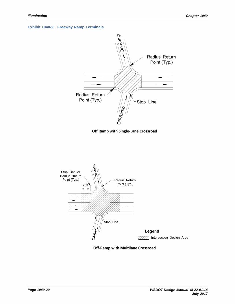
Provide the necessary illumination for the design area (see Exhibit 1040-2).

Illumination Chapter 1040
Page 1040-4 WSDOT Design Manual M 22-01.14 July 2017
1040.04(3) Freeway On-Ramps With Ramp Meter Signals
Provide the necessary number of light standards to illuminate freeway on-ramps with ramp meters, from 150’ before the ramp meter stop bar to 50’ past the ramp meter stop bar. When there is an HOV bypass lane or a two-lane merge beyond the ramp meter, then also provide illumination from the point where the merging lane width is 10’ to 200’ downstream of that point (see Exhibit 1040-3). Illumination for the ramp merge with mainline is to be done per Exhibit 1040-1b.
1040.04(4) HOT (High-Occupancy Toll) Lane Enter/Exit Zones and Access Weave Lanes
Provide the necessary number of luminaires to illuminate the design area of the enter/exit zones and access weave lanes of the HOT lane (see Exhibits 1040-4a and 4b).
1040.04(5) Lane Reduction
Provide the necessary number of light standards to illuminate the design area of all highway lane reduction areas within the urban boundary (see Exhibit 1040-5). This requirement does not apply to: • The end of slow-moving vehicle turnouts. • The end of the area where driving on shoulders is allowed.
1040.04(6) Intersections With Left-Turn Lane Channelization
Illumination of the intersection area is required for intersections with painted or other low-profile pavement markings such as raised pavement markings. When the channelization is delineated with curbs, raised medians, or islands, illuminate the raised channelization on the State Route from 25’ before the raised channelization begins (see Exhibits 1040-6a, 6b, and 6c).
1040.04(7) Intersections With Traffic Signals
Illuminate intersections with traffic signals on state highways (see Exhibit 1040-7). In cities with a population under 25,000, the state may assume responsibility for illumination installed on signal standards.
1040.04(8) Roundabouts
Provide the necessary number of light standards to illuminate the design areas of roundabouts (see Chapter 1320 and Exhibit 1040-9).
1040.04(9) Railroad Crossings with Gates or Signals
Railroad crossings with automated gates or signals on state highways are illuminated if there is nighttime train traffic. Within the corporate limits of a city, and outside limited access control, illumination is the responsibility of the city. Install luminaires beyond the railroad crossing, on the side of the roadway opposite the approaching traffic, to backlight the train (see Exhibit 1040-10).

Chapter 1040 Illumination
WSDOT Design Manual M 22-01.14 Page 1040-5 July 2017
1040.04(10) Midblock Pedestrian Crossings
Illuminate the entire midblock pedestrian crossing, including the crosswalks, the refuge area in the roadway, and the sidewalks or shoulders adjacent to the crosswalk. When a raised median pedestrian refuge design is used, illuminate the raised channelization (see Exhibit 1040-11).
1040.04(11) Transit Flyer Stops
Illuminate the pedestrian-loading areas of transit flyer stops located within the limited access boundaries (see Exhibit 1040-12).
1040.04(12) Major Parking Lots
All parking lots with usage exceeding 50 vehicles during the nighttime peak hour are considered major parking lots. Provide an illumination design that will produce the light levels shown in Exhibit 1040-22. (See Exhibit 1040-13 for the parking design area and bus loading zone design area.) During periods of low usage at night, security lighting is required only in the parking area and bus loading zone. Provide an electrical circuitry design that allows the illumination system to be reduced to approximately 25% of the required light level.
1040.04(13) Minor Parking Lots
Minor parking lots have a nighttime peak hour usage of 50 or fewer vehicles. Provide security-level lighting for those lots owned and maintained by the state. Security lighting for a minor parking lot consists of lighting the entrance and exit to the lot (see Exhibit 1040-14).
1040.04(14) Truck Weigh Sites
Provide illumination of the roadway diverge and merge sections, scale platforms, parking areas, and inspection areas of weigh sites (see Exhibit 1040-15).
1040.04(15) Safety Rest Areas
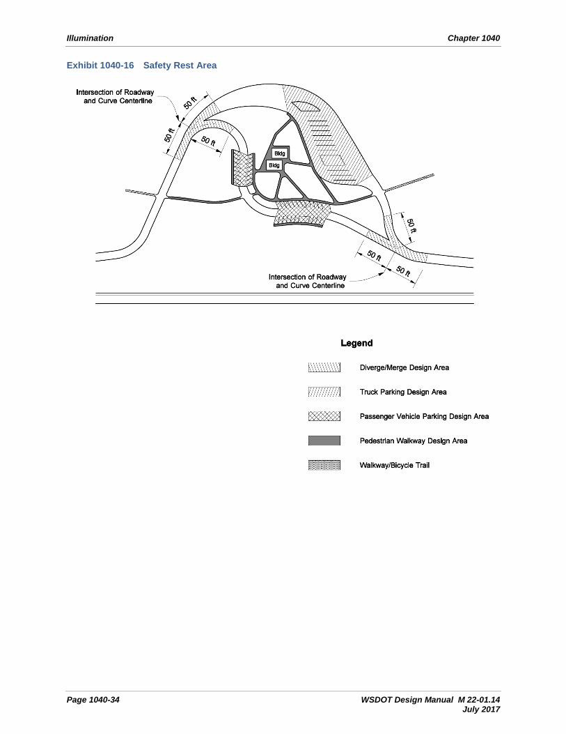
Provide illumination within rest areas at the roadway diverge and merge sections, the walkways between parking areas and rest room buildings, and the parking areas the same as for a major parking lot (see Exhibit 1040-16).
1040.04(16) Chain-Up/Chain-Off Parking Areas
Provide the necessary number of luminaires to illuminate the design area of the chain-up/chain-off parking areas (see Exhibit 1040-17) on State Routes 2, 12, and 90 where a power distribution point is within a half mile and power is readily accessible. Illumination is to be installed in the median and on the right shoulder to provide lighting on both sides of the stopped vehicles. Luminaires should only be energized during periods when traction tires are required and vehicles over 10,000 pounds are required to use chains.
1040.04(17) Tunnels, Lids, and Underpasses
For the purposes of this chapter, a tunnel is a structure over a roadway, which restricts the normal daytime illumination of a roadway section such that the driver’s visibility is substantially diminished. Tunnels cover roadways and produce a shadow that limits the ability of the driver to see objects or obstructions within the tunnel. In most locations, no supplemental daytime

Illumination Chapter 1040
Page 1040-6 WSDOT Design Manual M 22-01.14 July 2017
lighting is required for underpasses or structures less than 80 feet in length. Provide both nighttime and daytime lighting for long tunnels. (See ANSI/IES publication RP-22-11 for tunnel lighting design criteria.) Provide vandal-resistant daytime and nighttime security lighting in pedestrian tunnels. Short tunnels and underpasses where the exit portal is not visible from the entrance portal due to curvature of the roadway are to be considered long tunnels.
1040.04(18) Bridge Inspection Lighting
Provide the necessary number of light fixtures and electrical outlets to illuminate the interior inspection areas of floating bridges, steel box girder bridges and concrete box girder bridges where access is provided (see Exhibit 1040-18). Separate circuits are to be used for lighting and electrical outlets. Each electrical outlet is to be powered by 2 Duplex receptacles on two separate circuits. All electrical outlets are to be labeled with circuit identifications. Coordinate bridge illumination requirements with the HQ Bridge and Structures Office.
1040.04(19) Same Direction Traffic Split Around an Obstruction
Provide the necessary number of light standards to illuminate the design area where traffic is split around an obstruction. This requirement applies to permanent and temporary same-direction split channelization. For temporary work zones, illuminate the obstruction for the duration of the traffic split (see Exhibit 1040-19).
1040.04(20) Diverging Diamond Interchange
Provide the necessary number of light standards to illuminate the design area shown in Exhibit 1040-21. The design area starts 25’ before the raised channelization as you approach the interchange and continues through the interchange until 25’ past the raised channelization as you exit the interchange.
1040.05 Additional Illumination
At certain locations, additional illumination is desirable to provide better definition of nighttime driving conditions or to provide consistency with local agency goals and enhancement projects. For Improvement projects on state highways, additional illumination could be reviewed as a crash countermeasure under certain circumstances, which are listed in this section.
1040.05(1) Conditions for Additional Illumination
Following are some conditions used in making the decision to provide additional illumination:
1040.05(1)(a) Crash Analysis
The following conditions have to be met when making the decision to provide additional illumination:
• During the last full five calendar years, the site has experienced nighttime crashes that are correctable with illumination, AND
• The benefit-cost analysis for the proposed illumination exceeds 1, AND
• Alternative lower-cost countermeasures have been evaluated and did not address the particular nighttime crash history.

Chapter 1040 Illumination
WSDOT Design Manual M 22-01.14 Page 1040-7 July 2017
Nighttime crashes are defined as crashes occurring between half an hour after sunset and half an hour before sunrise. Correctable nighttime crashes are crashes that (a) meet the nighttime definition in this chapter, (b) have contributing factors related to a lack of lighting, and (c) where lighting, if installed, would directly address the contributing factor(s) to the crashes.
Collision reporting forms and the crash data are not adequate means to distinguish between day and nighttime conditions: the crash location, the reported crash times, and seasonal variations should be used to determine which crashes qualify as nighttime crashes. Also:
• For sites where the number of nighttime crashes equals or exceeds the number of daytime crashes, the above-mentioned crash and benefit-cost analysis should be performed.
• For sites where these nighttime crashes involve pedestrians, refer to 1040.05(11).
1040.05(1)(b) Locations With Nighttime Pedestrian Crashes
The mitigation of nighttime pedestrian crashes requires different lighting strategies than vehicular crash locations. Provide light levels to emphasize crosswalks and adjacent sidewalks by using positive lighting of the pedestrians.
Multilane highways with two-way left-turn lanes, in areas transitioning from rural land use to urban land use, or areas experiencing commercial growth or commercial redevelopment, are typically high-speed facilities with numerous road approaches and driveways. These approaches allow numerous vehicle entry and exit points and provide few crossing opportunities for pedestrians; consider additional illumination.
1040.05(2) Highways
Proposals to provide full (continuous) illumination require the approval of the Region and State Traffic Engineers. Regions may choose to develop (regional or corridor-specific) system plans for providing full (continuous) illumination. The State Traffic Engineer’s approval of a system plan will eliminate the need for a project-specific approval from the State Traffic Engineer. Continuous illumination can be provided inside city limits at the city’s request provided the city takes on the maintenance and operational costs and responsibilities of maintaining and operating the system.
The decision whether to provide full (continuous) illumination is to be made during the scoping stage and communicated to the designers as soon as possible.
Continuous illumination should be considered when the crash analysis requirements in 1040.05(1) are met and a benefit/cost analysis between the required and full (continuous) illumination exceeds 1.
On the main line of highways without full limited access control, consider full (continuous) illumination if the segment of highway is in a commercial area and the crash analysis requirements in 1040.05(1) are met, has raised channelization, has medium or high pedestrian activity during night time hours, and an engineering study indicates that nighttime driving conditions will be improved.
1040.05(3) Ramps
Consider additional illumination at ramps where the alignment or grade is complex.

Illumination Chapter 1040
Page 1040-8 WSDOT Design Manual M 22-01.14 July 2017
1040.05(4) Crossroads
Consider additional illumination if the crossroad is in a short tunnel, an underpass, or a lid.
1040.05(5) Intersections Without Turn-Lane Channelization
Refer to Exhibit 1040-8.
1040.05(6) Short Tunnels, Underpasses, or Lids
Consider illumination of the sidewalk, walkway, or shared-use path if it is included as part of the short tunnels, underpasses, or lids.
1040.05(7) Work Zones and Detours
Consider temporary illumination of the highway through work zones and detours when changes to the highway alignment or grade remain in place during nighttime hours. Exhibit 1040-20 illustrates considerations for temporary illumination, such as reduced roadway widths, work zone lane shifts, and median cross overs.
For further information on illumination in work zones, see Chapter 1010.
1040.05(8) Transit Stops
The responsibility for lighting at transit stops is shared with the transit agency. Consider illuminating transit stops with shelters as they usually indicate greater passenger usage. Negotiation with the transit agencies is required for the funding and maintenance of this illumination. Negotiating a memorandum of understanding (MOU) with each transit agency is preferred over spot negotiations. If the transit agency is unable or unwilling to participate in the funding and maintenance of the illumination, consider a single light standard positioned to illuminate both the transit pullout area and the loading area.
1040.05(9) Bridges
Justification for illuminating the roadway/sidewalk portion of bridges is the same as that for highways on either end of the bridge with or without full limited access control, as applicable. Justification for illuminating the architectural features of a bridge structure requires the approval of the State Traffic Engineer. For justification for illuminating pedestrian walkways or bicycle trails under a bridge, see 1040.05(11).
1040.05(10) Railroad Crossing Without Gates or Signals
Consider the illumination of railroad crossings without gates or signals when:
• The crash history indicates that motorists experience difficulty in seeing trains or control devices.
• There are a substantial number of rail operations conducted during nighttime hours.
• The crossing is blocked for long periods due to low train speeds.
• The crossing is blocked for long periods during the nighttime.
For further information, see the MUTCD.

Chapter 1040 Illumination
WSDOT Design Manual M 22-01.14 Page 1040-9 July 2017
1040.05(11) Sidewalks, Walkways, and Shared-Use Paths
Consider illumination of a pedestrian walkway if the walkway is a connection between two highway facilities. This could be between parking areas and rest room buildings at rest areas; between drop-off/pick-up points and bus loading areas at flyer stops; or between parking areas and bus loading areas or ferry loading zones. Consider illuminating existing sidewalks, walkways, and shared-use paths if security problems have been reported or are anticipated. Under these conditions, these facilities are illuminated to the level shown in Exhibit 1040-22.
1040.06 Design Criteria
1040.06(1) Light Levels
Light levels vary with the functional classification of the highway, the development of the adjacent area, and the level of nighttime activity. Light level requirements for highways and other facilities are shown in Exhibit 1040-22. These levels are the minimum average light levels required for a design area at the end of rated lamp life for applications requiring a spacing calculation. Light level requirements are not applicable for single light standards or security lighting installations where:
• The light level is reduced to approximately 25% of the required light level in parking lots and parking lot loading areas during periods of low usage at night.
• Walkway or path illumination is installed only at areas where shadows and horizontal and vertical geometry obstruct a pedestrian’s view.
• Light level requirements are applicable when:
• The complete walkway or path is to be illuminated for public safety.
The access areas used for interior inspection of floating bridges or steel box/concrete box girder bridges are exempt from lighting level and lighting ratio design requirements.
For functional classifications of highways, see: www.wsdot.wa.gov/mapsdata/travel/hpms/functionalclass.htm
1040.06(1)(a) Activity Areas
The types of activity areas (shown below) are related to the number of pedestrian crossings through the design area. These crossings need not occur within a single crosswalk and can be at several locations along the roadway in an area with pedestrian generators. Land use and activity classifications are as follows:
1040.06(1)(a)(1) High Activity
Areas with over 100 pedestrian crossings during nighttime peak hour pedestrian usage. Examples include downtown retail areas; near outdoor stage theaters, concert halls, stadiums, and transit terminals; and parking areas adjacent to these facilities.
1040.06(1)(a)(2) Medium Activity
Areas with pedestrian crossings that number between 11 and 100 during nighttime peak hour pedestrian usage. Examples include downtown office areas; blocks with libraries, movie

Illumination Chapter 1040
Page 1040-10 WSDOT Design Manual M 22-01.14 July 2017
theaters, apartments, neighborhood shopping, industrial buildings, and older city areas; and streets with transit lines.
1040.06(1)(a)(3) Low Activity
Areas with pedestrian crossings that number less than 11 during the nighttime peak hour pedestrian usage. Examples include suburban single-family areas, low-density residential developments, and rural or semirural areas.
1040.06(2) Design Areas
The design area is that portion of the roadway, parking lot, or other facility subject to the minimum light level, minimum average light level, uniformity ratio, and maximum veiling luminance ratio design requirements. This encompasses the area between the edges of the traveled way along the roadway; the outer edges of the stopping points at intersections; and, when present, a bike lane adjacent to the traveled way. When the roadway has adjacent sidewalks and is located in a medium or high pedestrian activity area, the design area includes these features; however, sidewalks adjacent to the traveled way are exempt from maximum veiling luminance ratio requirements.
1040.06(2)(a) Design Area Requirements
Design area requirements for various applications are shown in Exhibits 1040-1a through 1040-21 and are described in the following:
1040.06(2)(a)(1) Single-Lane Off-Ramp
Two main line through lanes and the ramp lane, including gore area, from the gore point (beginning of wide line) to a point 200 feet (minimum) downstream of the gore point. A 100 foot longitudinal tolerance either way from the gore point is allowed.
1040.06(2)(a)(2) Two-Lane Off-Ramp
Two main line through lanes and both ramp lanes, including gore area, from a point 200 feet upstream of the gore point (beginning of wide line) to a point 200 feet downstream of the gore point. A 100-foot longitudinal tolerance either way from the gore point is allowed.
1040.06(2)(a)(3) Single-Lane On-Ramp
Two main line through lanes and the ramp lane, from a point where the ramp lane is 10 feet wide to a point 200 feet downstream. A 100-foot longitudinal tolerance either way is allowed; this includes auxiliary lane on-connections and lane reductions.
1040.06(2)(a)(4) Two-Lane On-Ramp
Two main line through lanes and the ramp lanes from a point where the ramp width is 22 feet wide to a point 200 feet upstream and 200 feet downstream. A 100-foot longitudinal tolerance either way is allowed.
1040.06(2)(a)(5) Intersections Channelized With Pavement Markings
When the leg of an intersection is two lanes wide or less, the design area starts at the stop bar and encompasses the intersection area. When the leg of an intersection is three or more lanes wide, the design area starts 25’ before the stop bar and encompasses the intersection area.

Chapter 1040 Illumination
WSDOT Design Manual M 22-01.14 Page 1040-11 July 2017
1040.06(2)(a)(6) Intersections With Raised Channelization
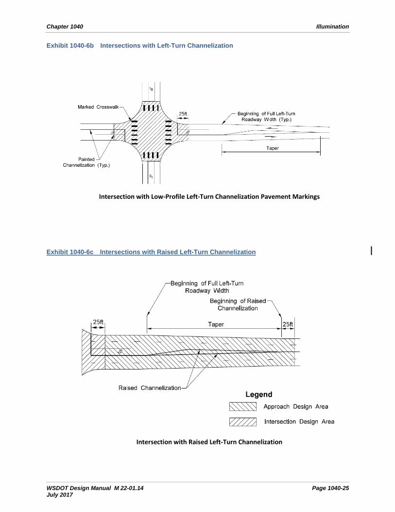
The design area has two components: the intersection area and the approach areas. When the leg of an intersection is two lanes wide or less, the intersection design area starts at the stop bar and encompasses the intersection area. When the leg of an intersection is three or more lanes wide, the intersection design area starts 25 feet before the stop bar and encompasses the intersection area on both the main road and the minor road, including marked or unmarked crosswalks. The approach areas are the areas on the main roadway between the intersection design area and where the left-turn taper begins.
1040.06(2)(a)(7) Unchannelized Intersection
The area between the stopping points on both the main road and the minor road, including marked or unmarked crosswalks.
1040.06(2)(a)(8) Railroad Crossing
The roadway width from a point 50 feet on either side of the track (the approach side only for one-way roadways).
1040.06(2)(a)(9) Transit Loading Area
The lane width and length designated for loading.
1040.06(2)(a)(10) Major Parking Lot
The entire area designated for parking, including internal access lanes.
1040.06(2)(a)(11) Scale Platform at Weigh Site
The approach width from the beginning of the scale platform to the end of the platform.
1040.06(2)(a)(12) Inspection Area at Weigh Site
The area dedicated to inspection as agreed upon with the Washington State Patrol.
1040.06(2)(a)(13) Bridge Inspection Lighting System
Fixtures are to be ceiling mounted. For steel box girders bridges, the spacing shall not be greater than the smaller of 4 times the web depth or 25 ft. For concrete box girder bridges, the spacing shall not be greater than the smaller of 8 times the web depth or 50 ft. Illumination is to consists of a 100 watt incandescent (or fluorescent equivalent) fixture. The bulb should have a minimum of 1600 lumens. Each fixture is to be designed with a 20 amp rated ground fault circuit interrupt (GFCI) receptacle. A light switch is needed at each entrance to any common inspection area. For inspection areas with two or more entrances, three-way or four-way switches are required.
1040.06(3) Daytime Light Levels for Tunnels, Lids, and Underpasses
It is important to provide sufficient illumination inside a tunnel. When driving into and through a tunnel during the day, a driver’s eyes have to adjust from a high light level (daylight) to a lower lighting level inside the tunnel. Motorists require sufficient time for their eyes to adapt to the lower light level of the tunnel itself. When sufficient lighting is not provided in the threshold, transition, or interior zones of a tunnel, a motorist’s eyes may not have enough time to adapt and may experience a “black hole” or “blackout” effect. This “black hole” effect may cause a motorist to slow down, reducing the efficiency of the roadway. When leaving the tunnel, the
Illumination Chapter 1040
Page 1040-12 WSDOT Design Manual M 22-01.14 July 2017
driver’s eyes have to adjust from a low lighting level back to daytime conditions. The full design considerations for tunnel lighting are covered in 1040.08(2) in the Design Guidance section.
• All designs for illuminating tunnels are to be reviewed and approved by the State Traffic Engineer.
• Long tunnels are divided into zones for the determination of daytime light levels. The zones are Threshold Zone, Transition Zone(s), and Interior Zone. Each zone length is calculated using the method described in ANSI/IES RP-22-11.
• The designer of a long tunnel shall perform a Lseq (Equivalent Veiling Luminance) calculation. Lseq values obtained from this calculation shall be used to reduce (or increase) the Suggested Daytime Maintained Average Pavement Luminance Levels where indicated.
• Tunnel wall illumination is required.
• The approach and exit roadways shall have a nighttime luminance level of no less than one third of the tunnel interior level for one safe stopping sight distance (SSSD).
• Provide illumination of fire protection equipment, alarm pull boxes, phones, and emergency exits in long tunnels. (See NFPA 502 for additional information.)
• Short tunnels and underpasses in rural areas or with low pedestrian usage normally do not have daytime illumination. Short tunnels and underpasses in urban areas with high pedestrian usage may require daytime and nighttime illumination. Consultation with the affected local agency is recommended. Short tunnels and underpasses are treated the same as an entrance zone on a long tunnel to establish daytime light levels.
• Nighttime light level requirements for short tunnels on continuously illuminated roadways are the same as the light level required on the roadway outside the tunnel.
1040.06(4) Light Standards
1040.06(4)(a) Light Standards on State Highway Facilities
Light standards are the most common supports used to provide illumination for highway facilities. The 40-foot light standard with a slip bases and Type 1 mast arm is predominantly used on state highways. In areas with continuous illumination, 50-foot light standards may be used. Use Type 1 mast arms on all new systems and when modifying existing systems. Cities and counties may elect to use different mounting heights to address factors unique to their environments. On state highways, alternative colored light standards may be considered if requested by the city or county, provided they agree to pay any additional costs associated with this change.
The typical location for a light standard is on the right shoulder. When considering designs for light standards mounted on concrete barrier in the median, consider the total life cycle cost of the system, including the user costs resulting from lane closures required for relamping and repair operations, and higher maintenance costs since the work will most likely be done during night time hours due to decreased traffic volumes. Region Signal Maintenance approval is required for all median mounted luminaires except chain on/off areas. Light standards located in the vicinity of overhead power lines require a minimum 10 foot circumferential clearance from the power line (including the neutral conductor) to any portion of the light standard or luminaire. Depending on the line voltage, a distance greater than 10 feet may be required (WAC

Chapter 1040 Illumination
WSDOT Design Manual M 22-01.14 Page 1040-13 July 2017
296-24-960). Consult the HQ Bridge and Structures Office when mounting light standards on structures such as retaining walls and bridge railings.
It is preferable to locate a light standard as far from the traveled way as possible to reduce the potential for impacts from errant vehicles. The typical luminaire position is mounted directly over the edge line plus or minus 4 feet. However, some flexibility is acceptable with the luminaire position to allow for placement of the light standard provided light levels, uniformity, and maintenance considerations are also addressed and with the Region Traffic Engineer’s approval. On Type III signal standards, luminaires may be placed more than 4 feet from the edge line.
Standard mast arm lengths are available in 2-foot increments between 6 and 16 feet. The preferred design for a single-arm light standard is a 16-foot mast arm installed on a 40-foot standard. The maximum allowable mast arm length for a single-arm light standard is 16 feet. The preferred design for a double mast arm light standard has mast arms between 6 feet and 12 feet in length, installed on a 40-foot standard. The maximum allowable mast arm length for a double luminaire light standard is 12 feet.
When light standards are located within the Design Clear Zone, breakaway and slip base features are used to reduce the severity of an impact. (See Chapter 1600 for additional guidance on clear zone issues.)
In curb and sidewalk sections, locate the light standard behind the sidewalk. In locations where the light standard cannot be placed behind the sidewalk and still have the luminaire mounted within 4’ of the edge line, the luminaire should be located in the sidewalk. Slip bases on light standards are a safety requirement for roadways where the posted speed is 35 mph or higher. They are not always desirable at other locations. Fixed bases are installed in the following locations: • Roadway with speeds below 35 mph. • Parking lots. • Medians where the light standard is mounted on median barrier. • Behind traffic barrier, beyond the barrier’s deflection design value (see Chapter 1610). • Along pedestrian walkways, bike paths, and shared-use paths outside of the roadway
clear zone.
1040.06(4)(b) Light Standard Heights
Standard pole heights (20-foot, 30-foot, or 40-foot) are readily available from local distributors and manufacturers. Light standards can also be supplied with other lengths. However, WSDOT Maintenance offices cannot stock poles with nonstandard lengths for use as replacements in the event of a knockdown. Nonstandard lengths in 5-foot increments (25-foot, 35-foot, or 45-foot) will require a longer delivery time. Other nonstandard lengths (for example, 27-foot, 33-foot, or 37-foot) will not only require a longer delivery time, they will also be more expensive.
In almost all cases, use a standard pole heights of 40 feet for roadway illumination. Structure-mounted light standards may need to be shorter than the standard 40-foot grade-mounted pole. It is acceptable to use 20-foot or 30-foot light standards on bridges, retaining walls, or other structures to compensate for top-of-structure elevation above the roadway surface. Luminaires with a mounting height over 40 feet should only be used in continuously illuminated areas that are not in residential areas. Use of these standard pole heights will result in variable mounting heights for the luminaires. Luminaire mounting height is defined as the actual

Illumination Chapter 1040
Page 1040-14 WSDOT Design Manual M 22-01.14 July 2017
distance from the roadway surface directly under the luminaire to the luminaire itself. Use the actual mounting height at each location when calculating light standard spacing. Luminaires with a mounting height over 50 feet require lowering devices.
High mast light supports may be considered for complex interchanges where continuous lighting is justified. High mast lighting may be considered for temporary illumination areas during construction. Initial construction costs, long-term maintenance, clear zone mitigation, spillover light onto adjacent properties, and negative visual impacts are important factors when considering high mast illumination.
Shorter light standards of 30 feet or less may be used for minor parking lots, trails, pedestrian walkways, and locations with restricted vertical clearance.
1040.06(4)(c) Standard Luminaire
The standard luminaire in use now for roadway lighting is a cobra head style type III LED fixture. The list of LED fixtures approved for use on WSDOT projects can be found at: http://www.wsdot.wa.gov/Design/Traffic/ledluminaires.htm
For continuously illuminated area a type V distribution pattern can be used for the interior areas with type III distribution on the perimeters.
1040.06(4)(d) Electrical Design
For an example of circuit layout, conductor sizing, conduit sizing, overcurrent protection device sizing, and other electrical design calculations, see the Power Supply Design material located at: http://www.wsdot.wa.gov/design/traffic/electrical/training.htm
An example of illumination design grid layouts and calculations is located in the Illumination Design for Transportation Applications material located in the link above.
The illumination circuitry is to be laid out so that if four or more luminaires are installed, it should have a minimum of two circuits. The intent is to make sure that if a circuit fails, there will still be partial lighting from the other circuits.
The maximum allowable junction box spacing is as follows:
1. 360 feet allowed between in grade junction boxes with a straight pull.
2. 180 feet when conduit run is along a curve or when the conduit makes a 30 degree or greater change in direction.
3. 180 feet between NEMA junction boxes in traffic barrier, retaining wall, or structure.
4. A junction box is required within 5 feet minimum (preferred) & 10 feet maximum of the luminaire base, regardless of the luminaire spacing.
5. 360 feet between NEMA junction boxes when fiber optic cable is run through conduit in traffic barrier, retaining wall, or structure.
6. Pull Box interconnect to Traffic Signal – spacing is 500 feet maximum. Disclaimer: This would only apply to a single fiber optic cable.
7. 1,000 feet between cable vaults or pull boxes – main line fiber optic cable.

Chapter 1040 Illumination
WSDOT Design Manual M 22-01.14 Page 1040-15 July 2017
1040.06(5) Adaptive Lighting
Adaptive Lighting Systems may be used at select locations where changing traffic conditions allow for lowering of light levels or the changing of a required design area. Some examples would be: the Pedestrian/Area Classification changes requiring different levels; traffic volumes drop sharply; or chain up/chain off areas. Region and State Traffic Engineers’ approval is required for adaptive lighting systems.
1040.07 Documentation
Justify and document any additional illumination in the Design Documentation Package (DDP).
The approval from maintenance to install median mounted luminaires can be an email or memo from the area maintenance superintendent and is kept in the design file.
Any areas in this section that says to “consider” a design element should have the logic of the consideration and decision documented in the design file for future reference.
Refer to Chapter 300 for design documentation requirements.
1040.08 References
1040.08(1) Federal/State Laws and Codes
National Electrical Code (NEC), NFPA, Quincy, MA
Revised Code of Washington (RCW) 47.24.020, Jurisdiction, control
Washington Administrative Code (WAC) 296-24-960, Working on or near exposed energized parts
WAC 468-18-040, Design standards for rearranged county roads, frontage roads, access roads, intersections, ramps and crossings
WAC 468-18-050, Policy on the construction, improvement and maintenance of intersections of state highways and city streets
1040.08(2) Design Guidance
American National Standard Practice for Roadway Lighting, IES RP-8-00, New York, NY 2000
Manual on Uniform Traffic Control Devices for Streets and Highways, USDOT, FHWA; as adopted and modified by Chapter 468-95 WAC “Manual on uniform traffic control devices for streets and highways” (MUTCD)
NFPA 502: Standard for Road Tunnels, Bridges, and Other Limited Access Highways, NFPA, Quincy, MA 2011
Recommended Practice for Tunnel Lighting, IESNA RP-22-05, New York, NY 2011
Roadway Lighting Design Guide, AASHTO, October 2005

Illumination Chapter 1040
Page 1040-16 WSDOT Design Manual M 22-01.14 July 2017
Roadway Lighting Handbook, Addendum to Chapter Six: Designing the Lighting System Using Pavement Luminance, Federal Highway Administration, Addendum to Implementation Package 78-15, Washington, DC 1983
Roadway Lighting Handbook, Federal Highway Administration, Implementation Package 78-15, Washington, DC 1978 (Reprinted April 1984)
Standard Plans for Road, Bridge, and Municipal Construction (Standard Plans), M 21-01, WSDOT
1040.08(3) Supporting Information
A Policy on Geometric Design of Highways and Streets (Green Book), AASHTO, Current Edition
An Informational Guide for Roadway Lighting, AASHTO, Washington, DC 1984
City Streets as Part of State Highways Guidelines Reached by the Washington State Department of Transportation and the Association of Washington Cities on Interpretation of Selected Topics of RCW 47.24 and Figures of WAC 468-18-050 for the Construction, Operations and Maintenance Responsibilities of WSDOT and Cities for such Streets, 4-30-1997 amended 4-2-2013
Light Trespass: Research Results and Recommendations, IES TM-11-00, New York, NY 2000

Chapter 1040 Illumination
WSDOT Design Manual M 22-01.14 Page 1040-17 July 2017
Exhibit 1040-1a Freeway Lighting Applications
Required Illumination for a Typical Diamond Interchange Shown for single-lane ramp connection and a two-lane crossroad without channelization.
Single-Lane Off-Connection The design area may be shifted up to 100 ft from the beginning of the wide line; a minimum
of two light standards of standard pole height required for design area.
Two-Lane Off-Connection: One Exit Only Lane; One Optional Lane The design area may be shifted up to 100 ft from the beginning of the wide line; a minimum of
three light standards of standard pole height required for design area.

Illumination Chapter 1040
Page 1040-18 WSDOT Design Manual M 22-01.14 July 2017
Exhibit 1040-1b Freeway Lighting Applications
Single-Lane On-Connection The design area may be shifted up to 100 ft from the 10-ft-wide ramp point; a minimum of
two light standards of standard pole height required for design area.
Auxiliary Lane at On-Connection
The design area may be shifted up to 100 ft from the end of wide line; a minimum of two light standards of standard pole height required for design area.
Two-Lane On-Connection: One Auxiliary Lane; One Merge Lane
The design area may be shifted up to 100 ft from the 22-ft-wide ramp point; a minimum of three light standards of standard pole height required for design area.

Chapter 1040 Illumination
WSDOT Design Manual M 22-01.14 Page 1040-19 July 2017
Exhibit 1040-1c Freeway Lighting Applications
Single Exit-Only Lane
The design area may be shifted up to 100 ft from the end of lane and the beginning of wide line; a minimum of two light standards of standard pole height required for design area.
Two Exit-Only Lanes
The design area may be shifted up to 100 ft from the end of lane and the beginning of wide line; a minimum of three light standards of standard pole height required for design area.
Illumination Chapter 1040
Page 1040-20 WSDOT Design Manual M 22-01.14 July 2017
Exhibit 1040-2 Freeway Ramp Terminals
Off Ramp with Single-Lane Crossroad
Off-Ramp with Multilane Crossroad

Chapter 1040 Illumination
WSDOT Design Manual M 22-01.14 Page 1040-21 July 2017
Exhibit 1040-3 Ramp with Meter
Single-Lane On-Ramp
Multilane On-Ramp with HOV Bypass Lane

Illumination Chapter 1040
Page 1040-22 WSDOT Design Manual M 22-01.14 July 2017
Exhibit 1040-4a HOT (High-Occupancy Toll) Lane Enter/Exit Zone
A minimum of two light standards of standard pole height required for each design area.

Chapter 1040 Illumination
WSDOT Design Manual M 22-01.14 Page 1040-23 July 2017
Exhibit 1040-4b HOT (High-Occupancy Toll) Lane ACCESS WEAVE LANE

Illumination Chapter 1040
Page 1040-24 WSDOT Design Manual M 22-01.14 July 2017
Exhibit 1040-5 Lane Reduction
A minimum of two light standards of standard pole height required for design area;
design area may be shifted 100 ft.
Exhibit 1040-6a Intersection with Left-Turn Channelization: Divided Highway
Chapter 1040 Illumination
WSDOT Design Manual M 22-01.14 Page 1040-25 July 2017
Exhibit 1040-6b Intersections with Left-Turn Channelization
Intersection with Low-Profile Left-Turn Channelization Pavement Markings
Exhibit 1040-6c Intersections with Raised Left-Turn Channelization
Intersection with Raised Left-Turn Channelization

Illumination Chapter 1040
Page 1040-26 WSDOT Design Manual M 22-01.14 July 2017
Exhibit 1040-7 Intersections with Traffic Signals
Four-Way Intersection with Single-Lane Approaches
Four-Way Intersection with Multilane Major Approaches A minimum of two light standards required for design area.
Minor Tee Intersection Major Tee Intersection A minimum of two light standards is
required for design area.

Chapter 1040 Illumination
WSDOT Design Manual M 22-01.14 Page 1040-27 July 2017
Exhibit 1040-8 Intersection without Channelization

Illumination Chapter 1040
Page 1040-28 WSDOT Design Manual M 22-01.14 July 2017
Exhibit 1040-9 Roundabout
Notes
1. Exclude Truck Apron from lighting calculations.
2. Exclude the portion inside the 2ft offset areas of the raised channelization islands from calculation.
3. All channelization 2ft wide or less is included in the Approach Design Area calculation.
4. When a leg of the roundabout is a one-way roadway, the Approach Design Area starts at the beginning of the raised channelization, or 50ft from the outside edge of the circulating roadway, or 50ft beyond a sidewalk, whichever is further.
5. A sidewalk is included in the Intersection Design Area calculation when a planting strip is less than 15ft wide.
6. Install luminaire to provide positive illumination of raised channelization. The preferred luminaire location would be from 20’ to one mounting height’s distance in front of the raised channelization.
7. Do not install luminaire in the area from 20’ in front of the crosswalk to 20’ past the crosswalk.
8. Install luminaire to provide positive illumination of the crosswalk for approaching vehicles. The preferred luminaire location would be one mounting height’s distance in front of the crosswalk.
9. If approach intersection area requires more than one luminaire, the last luminaire on that approach chain can be replaced with a ground-mounted, internally illuminated bollard with sign in place of 2nd luminaire.

Chapter 1040 Illumination
WSDOT Design Manual M 22-01.14 Page 1040-29 July 2017
Exhibit 1040-10 Railroad Crossing with Gates or Signals
Exhibit 1040-11 Midblock Pedestrian Crossing
A minimum of two light standards of standard height is required for the design area.

Illumination Chapter 1040
Page 1040-30 WSDOT Design Manual M 22-01.14 July 2017
Exhibit 1040-12 Transit Flyer Stop

Chapter 1040 Illumination
WSDOT Design Manual M 22-01.14 Page 1040-31 July 2017
Exhibit 1040-13 Major Parking Lot

Illumination Chapter 1040
Page 1040-32 WSDOT Design Manual M 22-01.14 July 2017
Exhibit 1040-14 Minor Parking Lot

Chapter 1040 Illumination
WSDOT Design Manual M 22-01.14 Page 1040-33 July 2017
Exhibit 1040-15 Truck Weigh Site
Illumination Chapter 1040
Page 1040-34 WSDOT Design Manual M 22-01.14 July 2017
Exhibit 1040-16 Safety Rest Area

Chapter 1040 Illumination
WSDOT Design Manual M 22-01.14 Page 1040-35 July 2017
Exhibit 1040-17 Chain-Up/Chain-Off Parking Area
Taper varies -See Ch. 1270
Taper varies -See Ch. 1270
End chain-up/chain-off areaBegin chain-up/ chain-off area
Full-width parking area
Legend
Design Area with 0.9 fc
Design Area with 1.6 fc

Illumination Chapter 1040
Page 1040-36 WSDOT Design Manual M 22-01.14 July 2017
Exhibit 1040-18 Bridge Inspection Lighting System

Chapter 1040 Illumination
WSDOT Design Manual M 22-01.14 Page 1040-37 July 2017
Exhibit 1040-19 Traffic Split Around an Obstruction
Note: For temporary work zone plan applications, a site-specific traffic control plan is required. Refer to Chapters 1610 and 1620 for traffic barrier and attenuator information, Chapter 1010 for work zone information, and Chapter 1020 for signing information.

Illumination Chapter 1040
Page 1040-38 WSDOT Design Manual M 22-01.14 July 2017
Exhibit 1040-20 Construction Work Zone and Detour
Detour Traffic
Lane Closure with Barrier and Signals without Flaggers or Spotters One-direction closure shown/other direction closure typical.
Note: For temporary work zone plan applications, a site-specific traffic control plan is required. Refer to Chapters 1610 and 1620 for traffic barrier and attenuator information, Chapter 1010 for work zone information, and Chapter 1020 for signing information. Refer to the MUTCD Typical Application 12 for additional details.

Chapter 1040 Illumination
WSDOT Design Manual M 22-01.14 Page 1040-39 July 2017
Exhibit 1040-21 Diverging Diamond Interchange

Illumination Chapter 1040
Page 1040-40 WSDOT Design Manual M 22-01.14 July 2017
Exhibit 1040-22 Light Levels and Uniformity Ratios
Light Level and Uniformity Ratio Chart
Highway Design Class
Minimum Average Maintained Horizontal Light Level [2] Maximum
Uniformity Ratio [5]
Maximum Veiling
Luminance Ratio [6]
Pedestrian/Area Classification
High (footcandles)
Medium (footcandles)
Low (footcandles)
Highways With Full Access Control [1][8]
Main Line 0.6 0.6 0.6 4:1 0.3:1
Ramps 0.6 0.6 0.6 4:1 0.3:1
Crossroads 0.6 0.6 0.6 4:1 0.3:1
Ramp Intersections 0.9 0.9 0.9 4:1 0.3:1
Highways Without Full Access Control [3][8]
Main Line 1.2 0.9 0.6 4:1 0.3:1
Intersections 1.2 0.9 0.9 4:1 0.3:1
Other Illuminated Features
Construction Lanes and Detours 1.0 1.0 1.0 4:1 0.3:1
Major Parking Lots/Rest Areas 0.8 0.8 0.8 4:1 0.3:1
Vehicle Inspection Areas 2.0 2.0 2.0 4:1 0.3:1
Sidewalks, Walkways & Shared Use Paths 0.8 0.8 0.8 4:1 0.3:1
Weigh Scales 0.8 0.8 0.8 4:1 0.3:1
Transit Stops [4] 2.0 2.0 2.0 NA [7] 0.3:1
Midblock Ped X-ing 2.0 2.0 2.0 4:1 0.3:1
Notes: [1] The minimum light level is 0.2 footcandle (fc) for any application with a minimum average maintained
horizontal light level of 0.6 fc. The minimum light levels for all other applications are controlled by the uniformity ratio.
[2] Light level and uniformity ratio apply only when installation of more than one light standard is justified. [3] Light levels shown also apply to modified and partial limited access control. [4] For single light standard installations, provide the light level at the location where the bus stops for riders
(see Exhibit 1040-12). [5] Minimum Average Maintained Light Level/Minimum Light Level = Maximum Uniformity Ratio. [6] Maximum Veiling Luminance/Average Luminance = Maximum Veiling Luminance Ratio. [7] The Maximum Uniformity Ratio is 4:1 when more than one light standard is justified. [8] Roundabout illumination shall meet intersection lighting requirements for the associated roadway classification.