chapter 10, solution 1. - egloospds2.egloos.com/pds/200610/29/98/solnchap10-vectorist.pdf ·...
TRANSCRIPT
Chapter 10, Solution 1. ω
1=
°∠→°− 45-10)45tcos(10 °∠→°+ 60-5)30tsin(5
jLjH1 =ω→
j-Cj
1F1 =
ω→
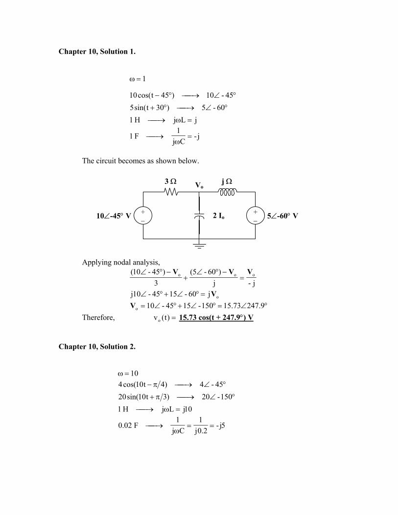
The circuit becomes as shown below.
Vo3 Ω
+ − 10∠-45° V +
− 2 Io
j Ω
5∠-60° V
Applying nodal analysis,
j-j)60-5(
3)45-10( ooo VVV
=−°∠
+−°∠
oj60-1545-10j V=°∠+°∠ °∠=°∠+°∠= 9.24715.73150-1545-10oV
Therefore, =)t(vo 15.73 cos(t + 247.9°) V
Chapter 10, Solution 2.
ω 10=°∠→π− 45-4)4t10cos(4
°∠→π+ 150-20)3t10sin(20 10jLjH1 =ω→
5j-2.0j
1Cj
1F02.0 ==
ω→
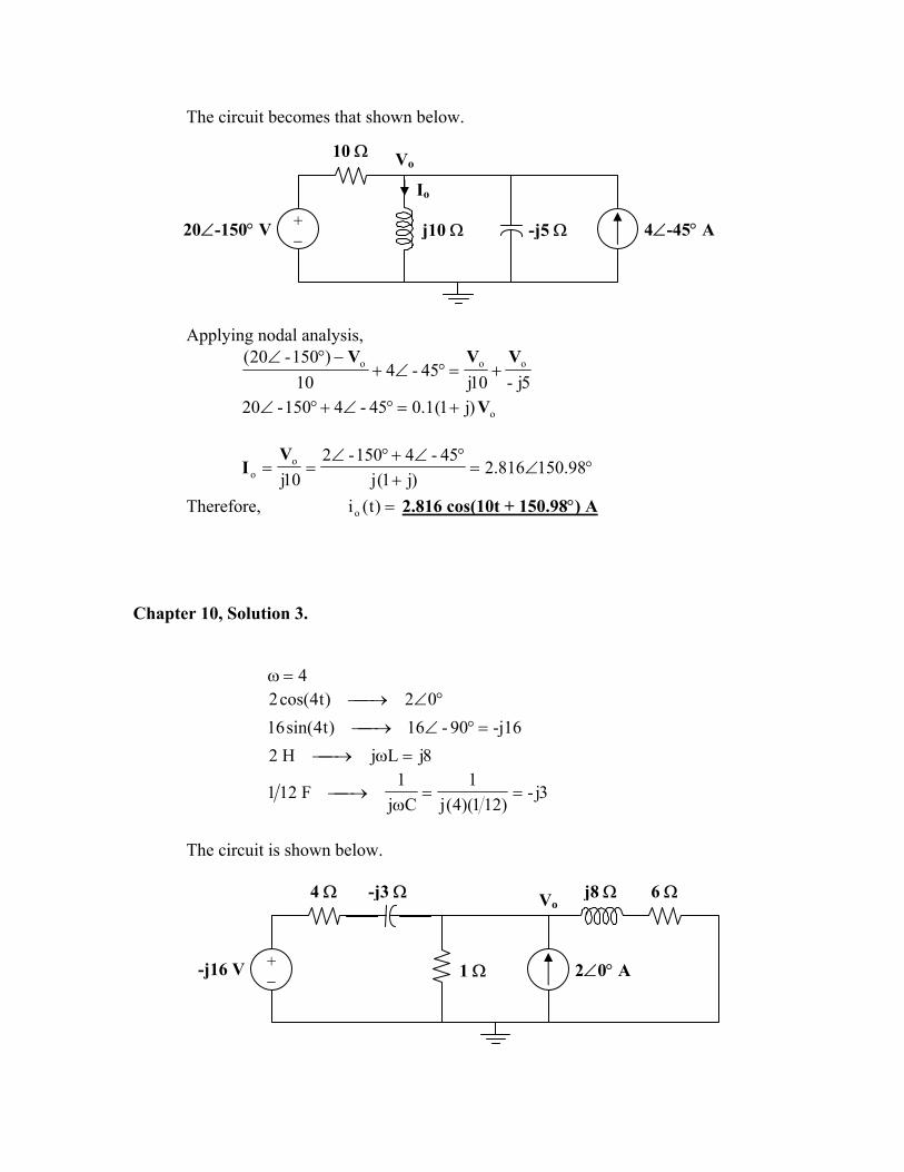
The circuit becomes that shown below.
Io
Vo10 Ω
j10 Ω -j5 Ω20∠-150° V + − 4∠-45° A
Applying nodal analysis,
5j-10j45-4
10)150-20( ooo VVV
+=°∠+−°∠
o)j1(1.045-4150-20 V+=°∠+°∠
°∠=+
°∠+°∠== 98.150816.2
)j1(j45-4150-2
10jo
o
VI
Therefore, =)t(io 2.816 cos(10t + 150.98°) A Chapter 10, Solution 3.
ω 4=°∠→ 02)t4cos(2
-j1690-16)t4sin(16 =°∠→ 8jLjH2 =ω→
3j-)121)(4(j
1Cj
1F121 ==
ω→
The circuit is shown below.
Vo
+ − 2∠0° A-j16 V
4 Ω -j3 Ω 6 Ω
1 Ω
j8 Ω
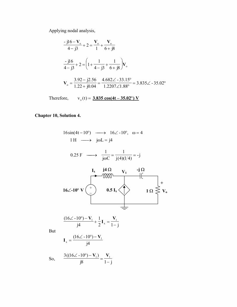
Applying nodal analysis,
8j612
3j416j- ooo
++=+
−− VVV
o8j61
3j41
123j4
16j-V
+
+−
+=+−
°∠=°∠°∠
=+−
= 02.35-835.388.12207.115.33-682.4
04.0j22.156.2j92.3
oV
Therefore, =)t(vo 3.835 cos(4t – 35.02°) V
Chapter 10, Solution 4.
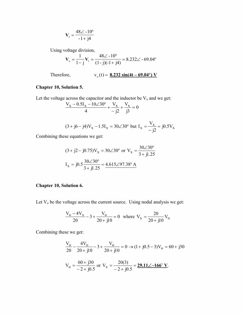
16 4,10-16)10t4sin( =ω°∠→°−
4jLjH1 =ω→
j-)41)(4(j
1Cj
1F25.0 ==
ω→
j4 Ω
1 Ω
Ix -j Ω
16∠-10° V + −
V1
0.5 Ix
+
Vo
−
j121
4j)10-16( 1
x1
−=+
−°∠ VI
V
But
4j)10-16( 1
x
VI
−°∠=
So, j18j
))10-16((3 11
−=
−°∠ VV
4j1-10-48
1 +°∠
=V
Using voltage division,
°∠=+°∠
=−
= 04.69-232.8)4j1j)(--(1
10-48j1
11o VV
Therefore, =)t(vo 8.232 sin(4t – 69.04°) V
Chapter 10, Solution 5. Let the voltage across the capacitor and the inductor be Vx and we get:
03j
V2j
V4
3010I5.0V xxxx =+−
+°∠−−
xx
xxx V5.0j2j
VIbut3030I5.1V)4j6j3( =−
=°∠=−−+
Combining these equations we get:
A38.97615.425.1j3
30305.0jI
25.1j33030Vor3030V)75.0j2j3(
x
xx
°∠=+
°∠=
+°∠
=°∠=−+
Chapter 10, Solution 6. Let Vo be the voltage across the current source. Using nodal analysis we get:
010j20
V3
20V4V oxo =
++−
− where ox V
10j2020V+
=
Combining these we get:
30j60V)35.0j1(010j20
V3
10j20V4
20V
oooo +=−+→=+
+−+
−
=+−
=+−+
=5.0j2
)3(20Vor5.0j2
30j60V xo 29.11∠–166˚ V.

Chapter 10, Solution 7. At the main node,
++
+
=−−+−
→+−
+∠=+
−−∠
501
30j
20j401V
3j196.520j40
058.31j91.11550V
30jV306
20j40V15120 o
o
V 15408.1240233.0j04.0
7805.4j1885.3V o−∠=+−−
=
Chapter 10, Solution 8.
,200=ω
20j1.0x200jLjmH100 ==ω→
100j10x50x200j
1Cj
1F50 6 −==ω
→µ−
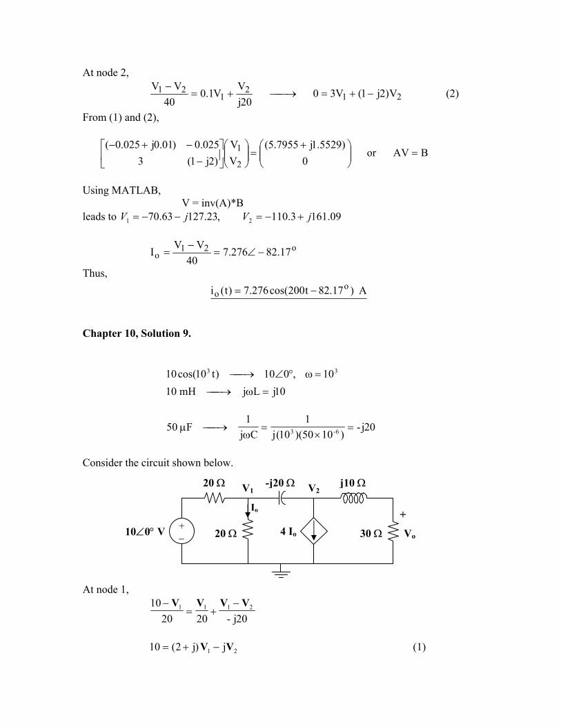
The frequency-domain version of the circuit is shown below.
0.1 Vo 40Ω V1 Io V2 + -j100Ω
6 o15∠ 20Ω Vo j20Ω -
At node 1,
40VV
100jV
20VV1.0156 2111
1o −
+−
+=+∠
or 21 025.0)01.0025.0(5529.17955.5 VVjj −+−=+ (1)
At node 2,
212
121 V)2j1(V30
20jV
V1.040
VV−+=→+=
− (2)
From (1) and (2),
BAVor0
)5529.1j7955.5(VV
)2j1(3025.0)01.0j025.0(
2
1 =
+=
−
−+−
Using MATLAB,
V = inv(A)*B leads to V 09.1613.110,23.12763.70 21 jVj +−=−−=
o21
o 17.82276.740
VVI −∠=
−=
Thus, A )17.82t200cos(276.7)t(i o
o −= Chapter 10, Solution 9.
10 33 10,010)t10cos( =ω°∠→
10jLjmH10 =ω→
20j-)1050)(10(j
1Cj
1F50 6-3 =
×=
ω→µ
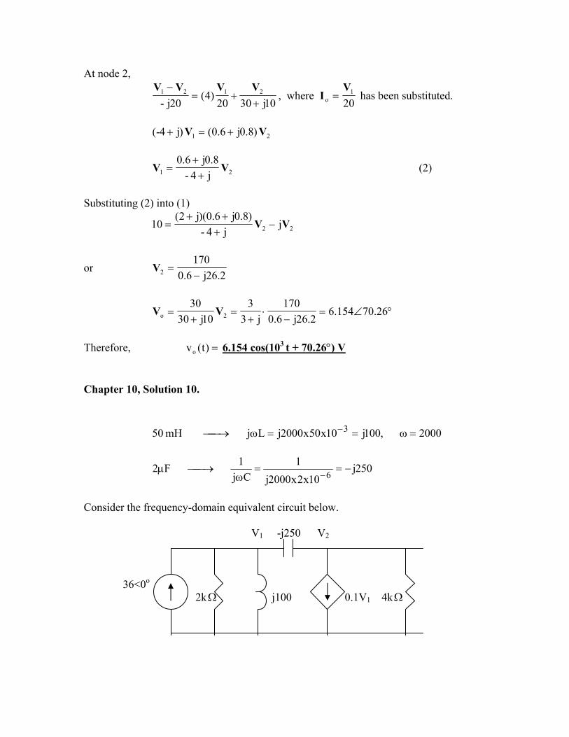
Consider the circuit shown below.
V120 Ω V2
-j20 Ω
20 Ω
Io
30 Ω
+
Vo
−
4 Io+ − 10∠0° V
j10 Ω At node 1,
20j-202010 2111 VVVV −
+=−
21 j)j2(10 VV −+= (1)
At node 2,
10j3020)4(
20j-2121
++=
− VVVV, where
201
o
VI = has been substituted.
21 )8.0j6.0()j4-( VV +=+
21 j4-8.0j6.0
VV++
= (2)
Substituting (2) into (1)
22 jj4-
)8.0j6.0)(j2(10 VV −
+++
=
or 2.26j6.0
1702 −=V
°∠=−
⋅+
=+
= 26.70154.62.26j6.0
170j3
310j30
302o VV
Therefore, =)t(vo 6.154 cos(103 t + 70.26°) V Chapter 10, Solution 10.
2000,100j10x50x2000jLj mH 50 3 =ω==ω→ −
250j10x2x2000j
1Cj
1F2 6 −==ω
→µ−
Consider the frequency-domain equivalent circuit below. V1 -j250 V2 36<0o 2kΩ j100 0.1V1 4kΩ
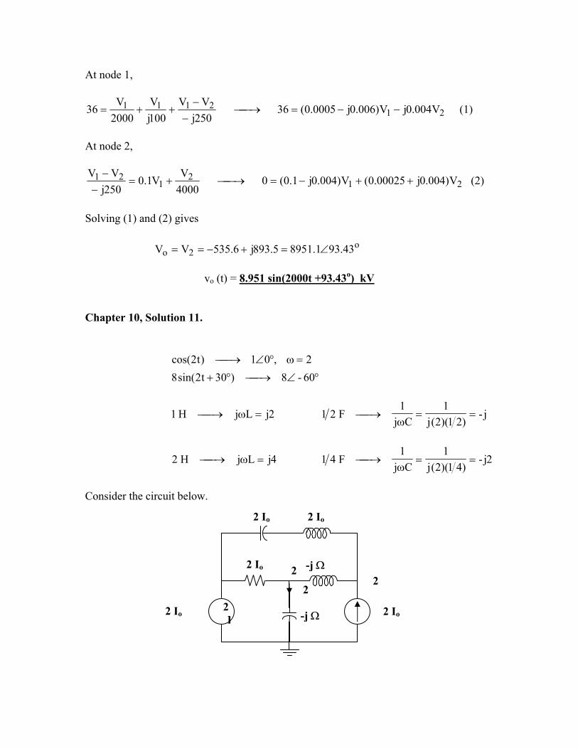
At node 1,
212111 V004.0jV)006.0j0005.0(36
250jVV
100jV
2000V
36 −−=→−−
++= (1)
At node 2,
212
121 V)004.0j00025.0(V)004.0j1.0(0
4000V
V1.0250j
VV++−=→+=
−−
(2)
Solving (1) and (2) gives
o2o 43.931.89515.893j6.535VV ∠=+−==
vo (t) = 8.951 sin(2000t +93.43o) kV
Chapter 10, Solution 11.
cos( 2,01)t2 =ω°∠→
°∠→°+ 60-8)30t2sin(8
2jLjH1 =ω→ j-)21)(2(j
1Cj
1F2 ==
ω→1
4jLjH2 =ω→ 2j-)41)(2(j
1Cj
1F4 ==
ω→1
Consider the circuit below.
-j Ω
-j Ω
2 Io
2 Io
2 Io 2 Io 2 I
2 2
2 Io
2
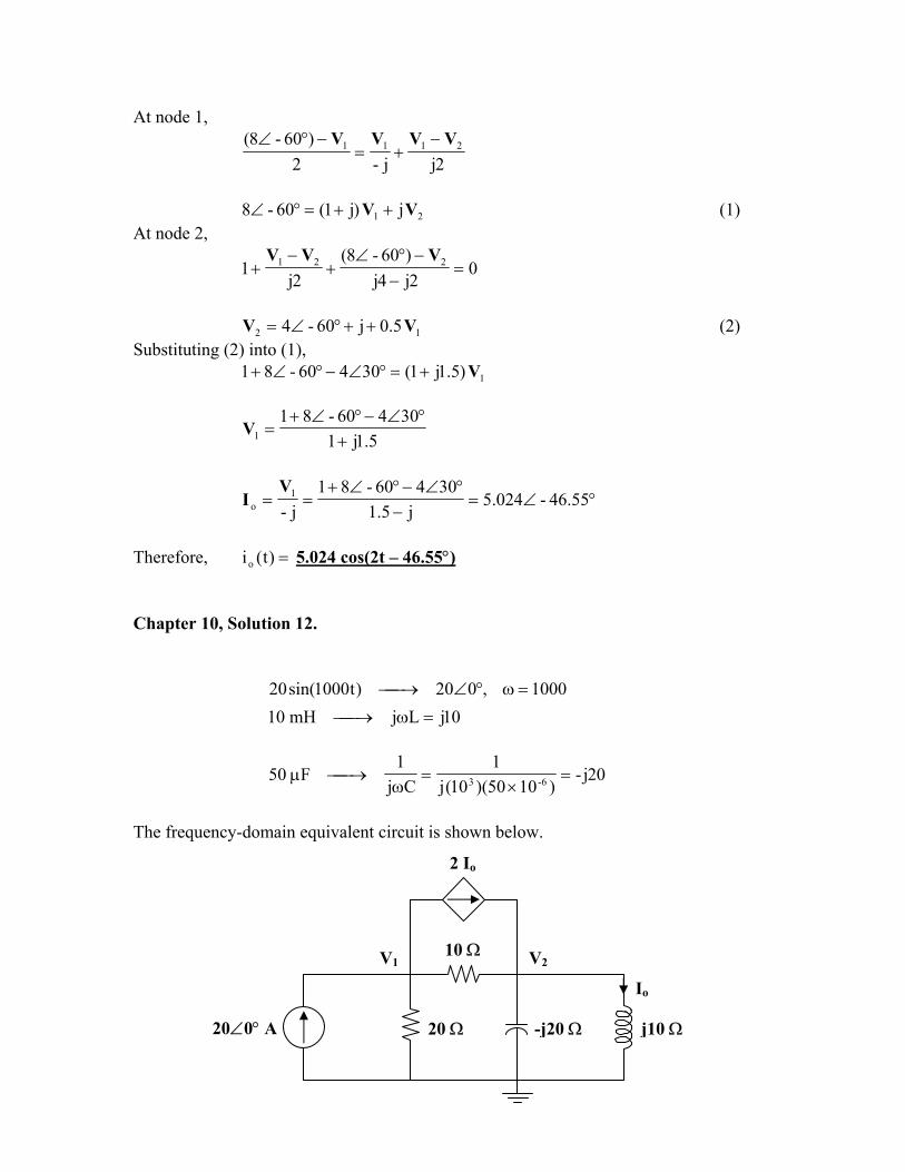
At node 1,
2jj-2)60-8( 2111 VVVV −
+=−°∠
21 j)j1(60-8 VV ++=°∠ (1)
At node 2,
02j4j)60-8(
2j1 221 =
−−°∠
+−
+VVV
12 5.0j60-4 VV ++°∠= (2)
Substituting (2) into (1), 1)5.1j1(30460-81 V+=°∠−°∠+
5.1j130460-81
1 +°∠−°∠+
=V
°∠=−
°∠−°∠+== 46.55-024.5
j5.130460-81
j-1
o
VI
Therefore, =)t(io 5.024 cos(2t – 46.55°) Chapter 10, Solution 12.
20 1000,020)t1000sin( =ω°∠→
10jLjmH10 =ω→
20j-)1050)(10(j
1Cj
1F50 6-3 =
×=
ω→µ
The frequency-domain equivalent circuit is shown below.
2 Io
-j20 Ω20 Ω
V2V1
20∠0° A
10 Ω
Io
j10 Ω
At node 1,
1020220 211
o
VVVI
−++= ,
where
10j2
o
VI =
102010j2
20 2112 VVVV −++=
21 )4j2(3400 VV +−= (1)
At node 2,
10j20j-1010j2 22212 VVVVV
+=−
+
21 )2j3-(2j VV +=
or (2) 21 )5.1j1( VV +=Substituting (2) into (1),
222 )5.0j1()4j2()5.4j3(400 VVV +=+−+=
5.0j1400
2 +=V
°∠=+
== 6.116-74.35)5.0j1(j
4010j
2o
VI
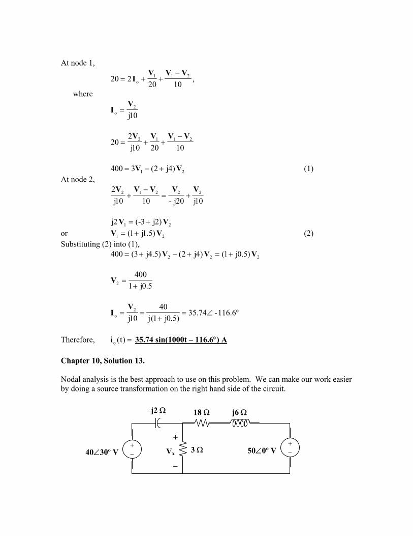
Therefore, =)t(io 35.74 sin(1000t – 116.6°) A Chapter 10, Solution 13. Nodal analysis is the best approach to use on this problem. We can make our work easier by doing a source transformation on the right hand side of the circuit. –j2 Ω 18 Ω j6 Ω
+ − 50∠0º V
+ −
+
Vx
−
3 Ω
40∠30º V
06j1850V
3V
2j3040V xxx =
+−
++−
°∠−
which leads to Vx = 29.36∠62.88˚ A.
Chapter 10, Solution 14.
At node 1,
°∠=−
+−
+−
30204j10
02j-
0 1211 VVVV
100j2.1735.2j)5.2j1(- 21 +=−+ VV (1)
At node 2,
°∠=−
++ 30204j5j-2j
1222 VVVV
100j2.1735.2j5.5j- 12 +=+ VV (2)
Equations (1) and (2) can be cast into matrix form as
°∠°∠
=
+3020030200-
5.5j-5.2j5.2j5.2j1
2
1
VV
°∠=−=+
=∆ 38.15-74.205.5j205.5j-5.2j5.2j5.2j1
°∠=°∠=°∠°∠
=∆ 120600)30200(3j5.5j-302005.2j30200-
1
°∠=+°∠=°∠°∠+
=∆ 7.1081020)5j1)(30200(302005.2j30200-5.2j1
2
°∠=∆∆
= 38.13593.2811V
°∠=∆∆
= 08.12418.4922V
)5.31381.15)(905.0(2j-1 °∠°∠==
VI
=I 7.906∠43.49° A
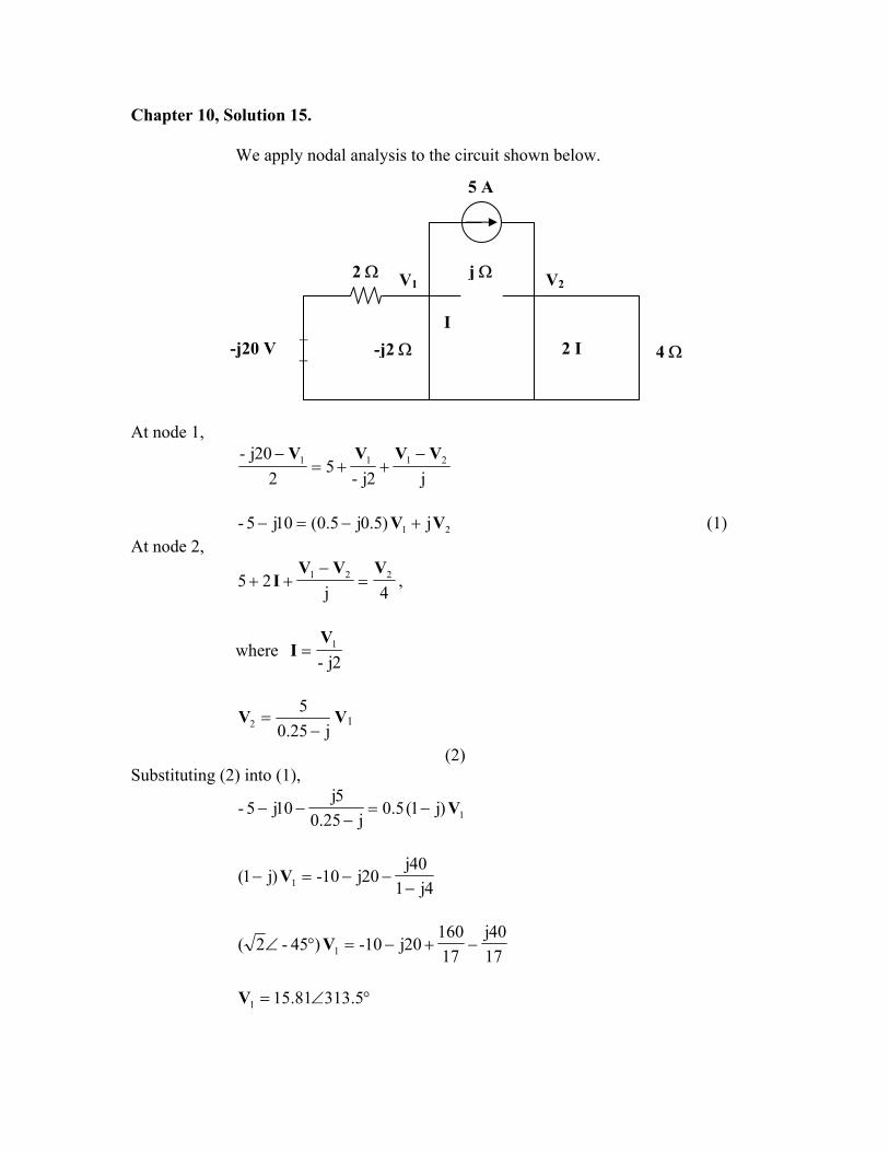
Chapter 10, Solution 16.
At node 1,
5j-10202j 21211 VVVVV −
+−
+=
21 )4j2()4j3(40j VV +−+= At node 2,
10jj1
5j-1022121 VVVVV
=++−
+−
21 )j1()2j1(-)j1(10 VV +++=+ Thus,
++++
=
+ 2
1
j1j2)(1-j2)(12-4j3
)j1(1040j
VV
°∠=−=++++
=∆ 11.31-099.5j5j1j2)(1-j2)(12-4j3
°∠=+−=+++
=∆ 96.12062.116100j60j1j)(110j2)(12-40j
1
°∠=+=++
+=∆ 29.129142.13j110-90
j)(110j2)(1-40j4j3
2
=∆∆
= 11V 22.87∠132.27° V
=∆∆
= 22V 27.87∠140.6° V
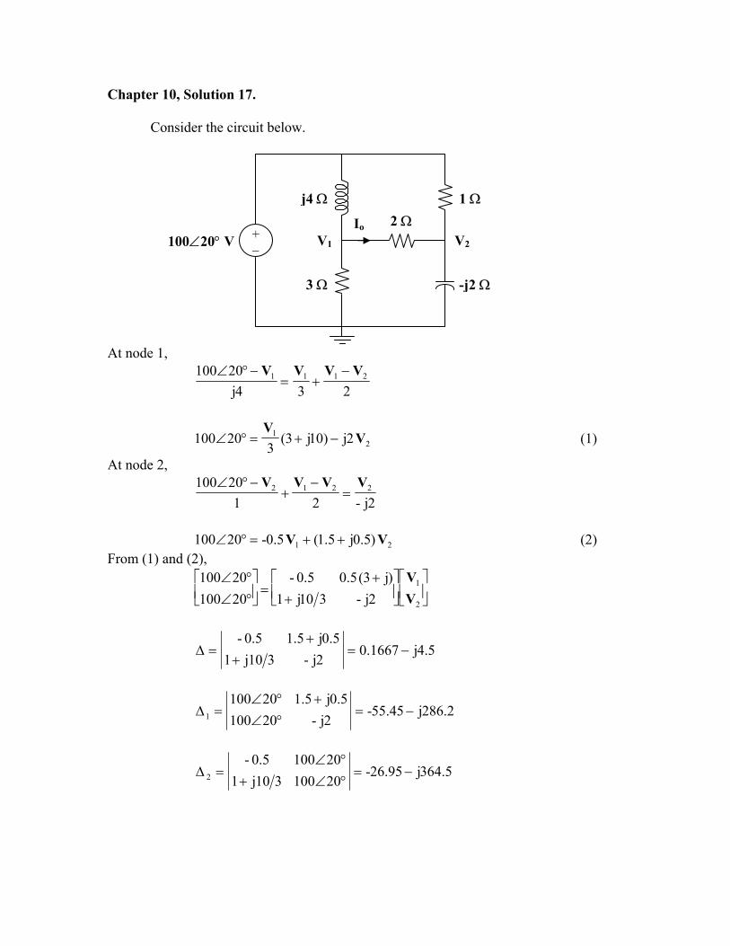
Chapter 10, Solution 17.
Consider the circuit below.
At node 1,
IoV2V1
j4 Ω
+ − 100∠20° V
2 Ω
-j2 Ω
1 Ω
3 Ω
234j20100 2111 VVVV −
+=−°∠
21 2j)10j3(
320100 V
V−+=°∠ (1)
At node 2,
2j-2120100 2212 VVVV
=−
+−°∠
21 )5.0j5.1(5.0-20100 VV ++=°∠ (2)
From (1) and (2),
+
+=
°∠°∠
2
1
2j-310j1)j3(5.05.0-
2010020100
VV
5.4j1667.02j-310j1
5.0j5.15.0-−=
++
=∆
2.286j45.55-2j-20100
5.0j5.1201001 −=
°∠+°∠
=∆
5.364j95.26-20100310j1201005.0-
2 −=°∠+°∠
=∆
°∠=∆∆
= 08.13-74.6411V
°∠=∆∆
= 35.6-17.8122V
9j3333.031.78j5.28-
222121
o −+
=∆∆−∆
=−
=VV
I
=oI 9.25∠-162.12°
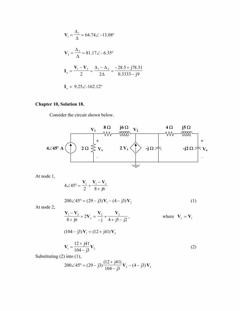
Chapter 10, Solution 18.
Consider the circuit shown below.
j6 Ω
2 Ω +
Vo
−
-j2 Ω
4 Ω j5 Ω
4∠45° A -j Ω+
Vx
−
2 Vx
8 ΩV1 V2
At node 1,
6j82454 211
+−
+=°∠VVV
21 )3j4()3j29(45200 VV −−−=°∠ (1)
At node 2,
2j5j4j-2
6j822
x21
−++=+
+− VV
VVV
, where VV =
1x
21 )41j12()3j104( VV +=−
21 3j10441j12
VV−+
= (2)
Substituting (2) into (1),
22 )3j4(3j104)41j12(
)3j29(45200 VV −−−+
−=°∠
2)17.8921.14(45200 V°∠=°∠
°∠°∠
=17.8921.14
452002V
222o 258j6-
3j42j-
2j5j42j-
VVVV−
=+
=−+
=
°∠°∠
⋅°∠
=17.8921.14
4520025
13.23310oV
=oV 5.63∠189° V
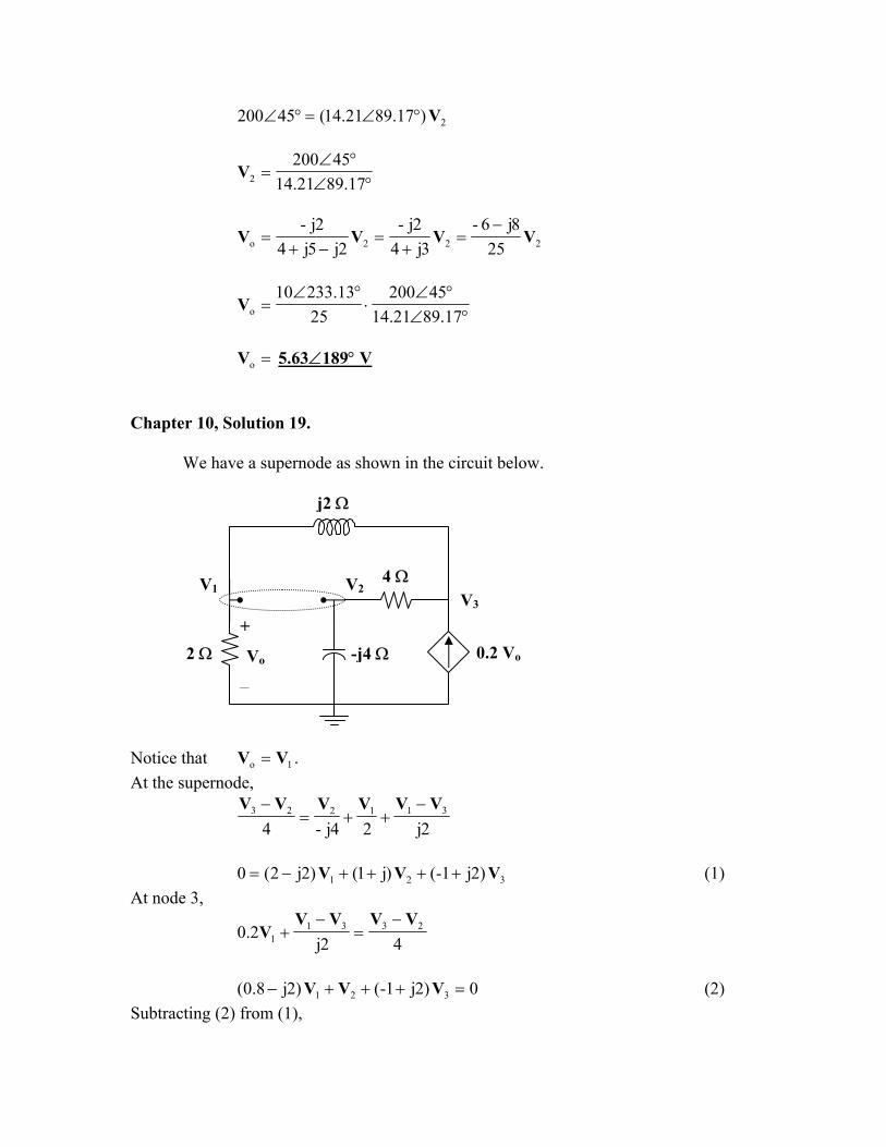
Chapter 10, Solution 19.
We have a supernode as shown in the circuit below.
j2 Ω
-j4 Ω+
Vo
−
V2V3
V1 4 Ω
2 Ω 0.2 Vo
Notice that . 1o VV =At the supernode,
2j24j-4311223 VVVVVV −
++=−
321 )2j1-()j1()2j2(0 VVV ++++−= (1)
At node 3,
42j2.0 2331
1
VVVVV
−=
−+
0)2j1-()2j8.0( 321 =+++− VVV (2)
Subtracting (2) from (1),
21 j2.10 VV += (3) But at the supernode,
21 012 VV +°∠= or (4) 1212 −= VVSubstituting (4) into (3),
)12(j2.10 11 −+= VV
o1 j2.112j
VV =+
=
°∠°∠
=81.39562.1
9012oV
=oV 7.682∠50.19° V
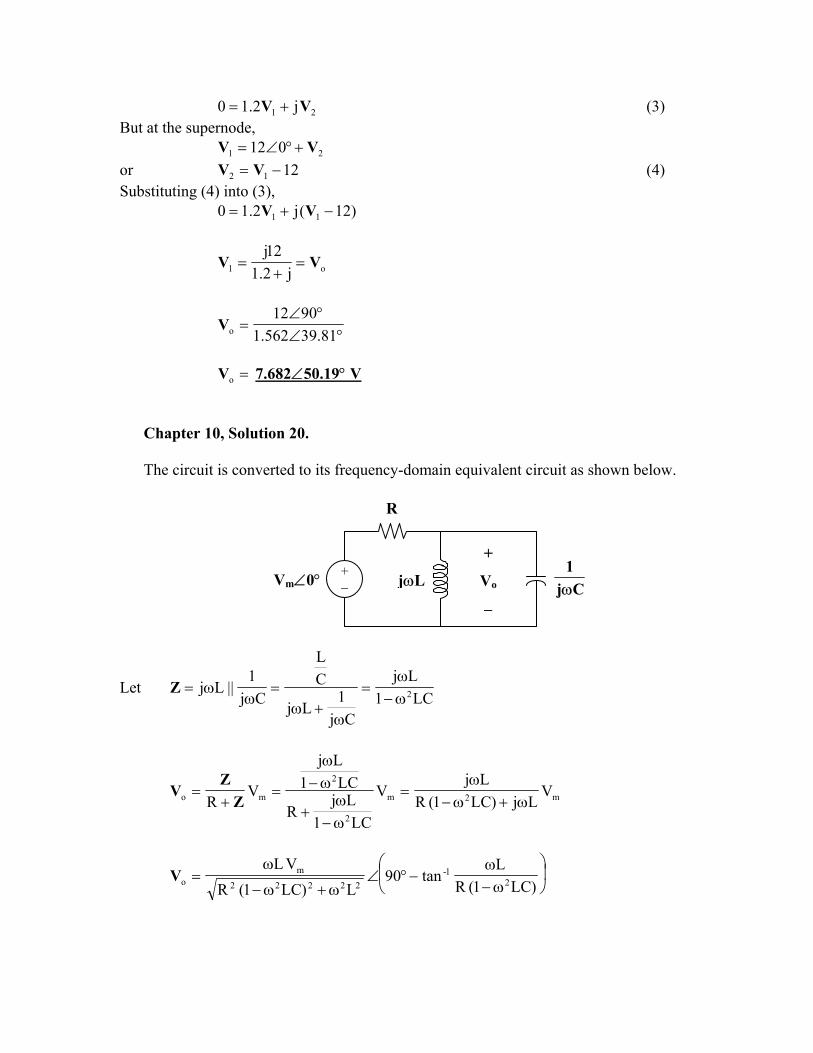
Chapter 10, Solution 20.
The circuit is converted to its frequency-domain equivalent circuit as shown below.
R
Cj1ω
+
Vo
−
jωL+ − Vm∠0°
Let LC1
Lj
Cj1
Lj
CL
Cj1
||Lj 2ω−ω
=
ω+ω
=ω
ω=Z
m2m
2
2
mo VLj)LC1(R
LjV
LC1Lj
R
LC1Lj
VR ω+ω−
ω=
ω−ω
+
ω−ω
=+
=Z
ZV
ω−ω
−°∠ω+ω−
ω=
)LC1(RL
tan90L)LC1(R
VL2
1-22222
moV
If , then
φ∠= AoV
=A22222
m
L)LC1(RVL
ω+ω−
ω
and =φ)LC1(R
Ltan90 2
1-
ω−ω
−°
Chapter 10, Solution 21.
(a) RCjLC1
1
Cj1
LjR
Cj1
2i
o
ω+ω−=
ω+ω+
ω=
VV
At , 0=ω ==11
i
o
VV
1
As ω , ∞→ =i
o
VV
0
At LC1
=ω , =⋅
=
LC1
jRC
1
i
o
VV
CL
Rj-
(b) RCjLC1
LC
Cj1
LjR
Lj2
2
i
o
ω+ω−ω−
=
ω+ω+
ω=
VV
At , 0=ω =i
o
VV
0
As ω , ∞→ ==11
i
o
VV
1
At LC1
=ω , =⋅
−=
LC1
jRC
1
i
o
VV
CL
Rj
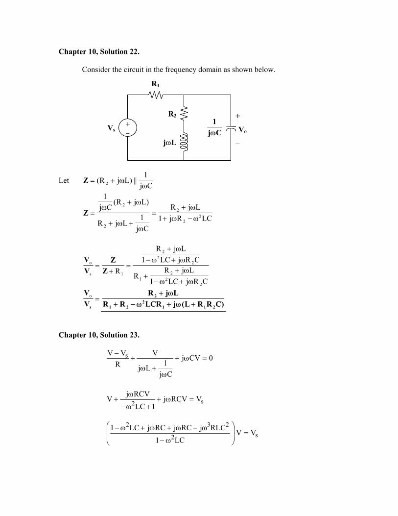
Chapter 10, Solution 22.
Consider the circuit in the frequency domain as shown below.
R1
Cj1ω
R2 +
Vo
−jωL
+ −
Vs
Let Cj
1||)LjR( 2 ω
ω+=Z
LCRj1LjR
Cj1
LjR
)LjR(Cj
1
22
2
2
2
ω−ω+ω+
=
ω+ω+
ω+ω
=Z
CRjLC1LjR
R
CRjLC1LjR
R2
22
1
22
2
1s
o
ω+ω−ω+
+
ω+ω−ω+
=+
=Z
ZVV
=s
o
VV
)CRRL(jLCRRRLjR
2112
21
2
+ω+ω−+ω+
Chapter 10, Solution 23.
0CVj
Cj1Lj
VR
VV s =ω+
ω+ω
+−
s2 VRCVj1LC
RCVjV =ω++ω−
ω+
s2
232VV
LC1RLCjRCjRCjLC1
=
ω−
ω−ω+ω+ω−
)LC2(RCjLC1V)LC1(V 22
s2
ω−ω+ω−
ω−=
Chapter 10, Solution 24.
For mesh 1,
22
121
s Cj1
Cj1
Cj1
IIVω
−
ω+
ω= (1)
For mesh 2,
22
12 Cj
1LjR
Cj1
0 II
ω+ω++
ω−
= (2)
Putting (1) and (2) into matrix form,
ω+ω+
ω−
ω−
ω+
ω=
2
1
22
221s
Cj1LjR
Cj1
Cj1
Cj1
Cj1
0 IIV
212
221 CC1
Cj1
LjRCj1
Cj1
ω+
ω+ω+
ω+
ω=∆
ω+ω+=∆
2s1 Cj
1LjRV and
2
s2 Cjω=∆
V
=∆∆
= 11I
212
221
2s
CC1
Cj1
LjRCj1
Cj1
Cj1
LjRV
ω+
ω+ω+
ω+
ω
ω+ω+
=∆∆
= 22I
212
221
2
s
CC1
Cj1
LjRCj1
Cj1
CjV
ω+
ω+ω+
ω+
ω
ω
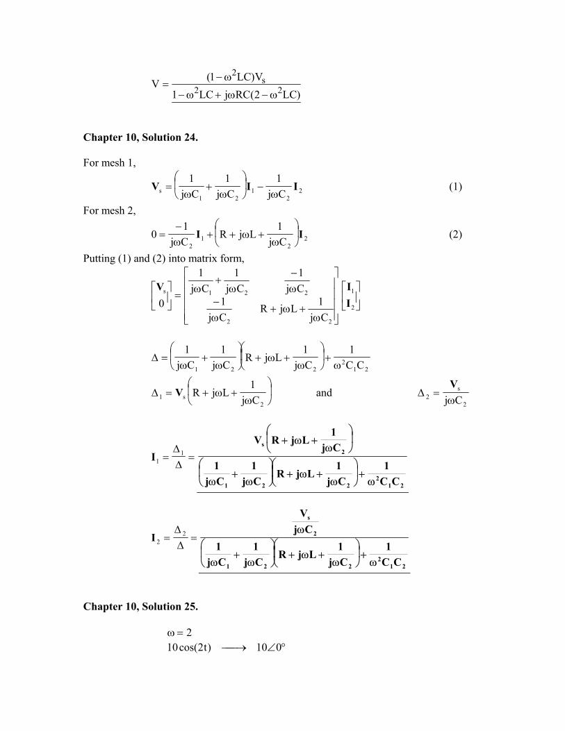
Chapter 10, Solution 25.
2=ω
°∠→ 010)t2cos(10
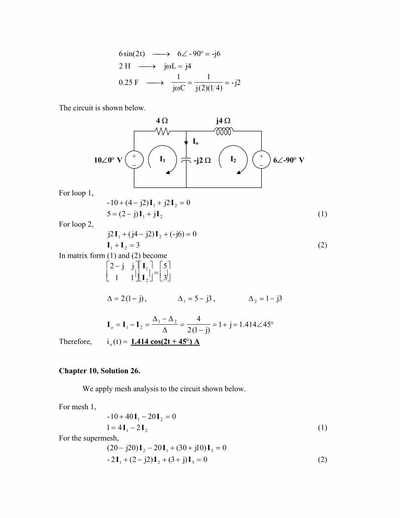
-j690-6)t2sin(6 =°∠→ 4jLjH2 =ω→
2j-)41)(2(j
1Cj
1F25.0 ==
ω→
The circuit is shown below.
4 Ω j4 Ω
For loop 1,
I2+ − 10∠0° V +
− -j2 ΩI1
Io
6∠-90° V
02j)2j4(10- 21 =+−+ II
21 j)j2(5 II +−= (1) For loop 2,
0)6j-()2j4j(2j 21 =+−+ II 321 =+ II (2)
In matrix form (1) and (2) become
=
−35
11jj2
2
1
II
)j1(2 −=∆ , 3j51 −=∆ , 3j12 −=∆
°∠=+=−
=∆∆−∆
=−= 45414.1j1)j1(2
42121o III
Therefore, =)t(io 1.414 cos(2t + 45°) A Chapter 10, Solution 26.
We apply mesh analysis to the circuit shown below. For mesh 1,
0204010- 21 =−+ II
21 241 II −= (1) For the supermesh,
0)10j30(20)20j20( 312 =++−− III 0)j3()2j2(2- 321 =++−+ III (2)
At node A, 21o III −= (3)
At node B, o32 4III += (4)
Substituting (3) into (4) 2132 44 IIII −+=
123 45 III −= (5) Substituting (5) into (2) gives
21 )3j17()4j14(-0 II +++= (6) From (1) and (6),
++
=
2
1
3j17)4j14(-2-4
01
II
4j40 +=∆
3j17j3170
2-11 +=
+=∆ , 4j14
0j4)(14-14
2 +=+
=∆
4j408j245
45 12123 +
+=
∆∆−∆
=−= III
°∠=++
== 25.70154.6j10
)4j1(1530 3o IV
Therefore, =)t(vo 6.154 cos(103 t + 70.25°) V Chapter 10, Solution 27.
For mesh 1,
020j)20j10j(3040- 21 =+−+°∠ II
21 2jj-304 II +=°∠ (1) For mesh 2,
020j)20j40(050 12 =+−+°∠ II
21 )2j4(2j-5 II −−= (2) From (1) and (2),
−
=
°∠
2
1
)2j4(-2j-2jj-
5304
II
°∠=+=∆ 56.116472.4j42-
°∠=−−°∠=∆ 8.21101.2110j)2j4)(304(-1
°∠=°∠+=∆ 27.15444.412085j-2
=∆∆
= 11I 4.698∠95.24° A
=∆∆
= 22I 0.9928∠37.71° A
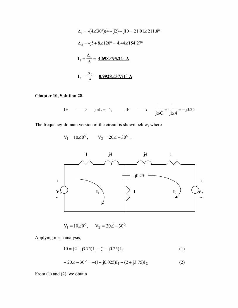
Chapter 10, Solution 28.
25.0j4x1j
1Cj
1F1,4jLjH1 −==ω
→=ω→
The frequency-domain version of the circuit is shown below, where
o2
o1 3020V,010V −∠=∠= .
1 j4 j4 1 -j0.25 + + V1 I1 1 I2 V2 - -
o2
o1 3020V,010V −∠=∠=
Applying mesh analysis,
21 I)25.0j1(I)75.3j2(10 −−+= (1)
(2) 21
o I)75.3j2(I)025.0j1(3020 ++−−=−∠− From (1) and (2), we obtain
++−+−+
=
+− 2
1II
75.3j225.0j125.0j175.3j2
10j32.1710
Solving this leads to
o2
o1 1536505.4111.2j1438.4I,69.356747.19769.0j3602.1I ∠=+−=−∠=−=
Hence,
A )15346cos(651.4i A, )69.35t4cos(675.1i o2
o1 +=−=
Chapter 10, Solution 29.
For mesh 1,
02030)j2()5j5( 21 =°∠−+−+ II
21 )j2()5j5(2030 II +−+=°∠ (1) For mesh 2,
0)j2()6j3j5( 12 =+−−+ II
21 )3j5()j2(-0 II −++= (2) From (1) and (2),
+
++=
°∠
2
1
j3-5j)(2-j)(2-5j5
02030
II
°∠=+=∆ 21.948.376j37
°∠=°∠°∠=∆ 96.10-175)96.30-831.5)(2030(1 °∠=°∠°∠=∆ 56.4608.67)56.26356.2)(2030(2
=∆∆
= 11I 4.67∠-20.17° A
=∆∆
= 22I 1.79∠37.35° A
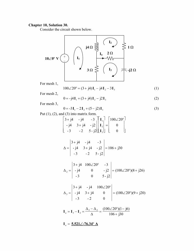
Chapter 10, Solution 30. Consider the circuit shown below.
For mesh 1,
I3
I1
I2
Io
j4 Ω
+ − 10∠0° V
2 Ω
3 Ω
1 Ω
-j2 Ω
321 34j)4j3(20100 III −−+=°∠ (1) For mesh 2,
321 2j)4j3(4j-0 III −++= (2) For mesh 3,
321 )2j5(23-0 III −+−= (3) Put (1), (2), and (3) into matrix form.
°∠=
++
00
20100
j2-52-3-j2-j43j4-3-j4-4j3
3
2
1
III
30j106j2-52-3-
j2-j43j4-3-j4-4j3
+=++
=∆
)26j8)(20100(j2-503-
j2-0j4-3-201004j3
2 +°∠=°∠+
=∆
)20j9)(20100(02-3-0j43j4-
20100j4-4j3
3 +°∠=+°∠+
=∆
30j106)6j1)(20100(23
23o +−°∠
=∆∆−∆
=−= III
=oI 5.521∠-76.34° A
Chapter 10, Solution 31.
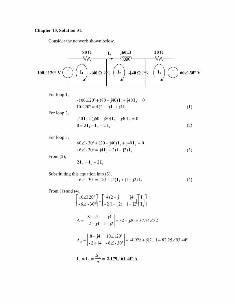
Consider the network shown below.
80 Ω j60 Ω 20 ΩIo
-j40 ΩI1 I3-j40 Ω+ − 100∠120° V +
− I2 60∠-30° V
For loop 1,
040j)40j80(20100- 21 =+−+°∠ II
21 4j)j2(42010 II +−=°∠ (1) For loop 2,
040j)80j60j(40j 321 =+−+ III
321 220 III +−= (2)
For loop 3, 040j)40j20(30-60 23 =+−+°∠ II
32 )2j1(24j30-6- II −+=°∠ (3) From (2),
123 22 III −= Substituting this equation into (3),
21 )2j1()2j1(2-30-6- II ++−=°∠ (4) From (1) and (4),
+−
−=
°∠°∠
2
1
2j1)2j1(2-4j)j2(4
30-6-12010
II
°∠=+=++
−=∆ 3274.3720j32
2j14j2-4j-4j8
°∠=+=°∠+°∠−
=∆ 44.9325.8211.82j928.4-30-6-4j2-
120104j82
=∆∆
== 22o II 2.179∠61.44° A
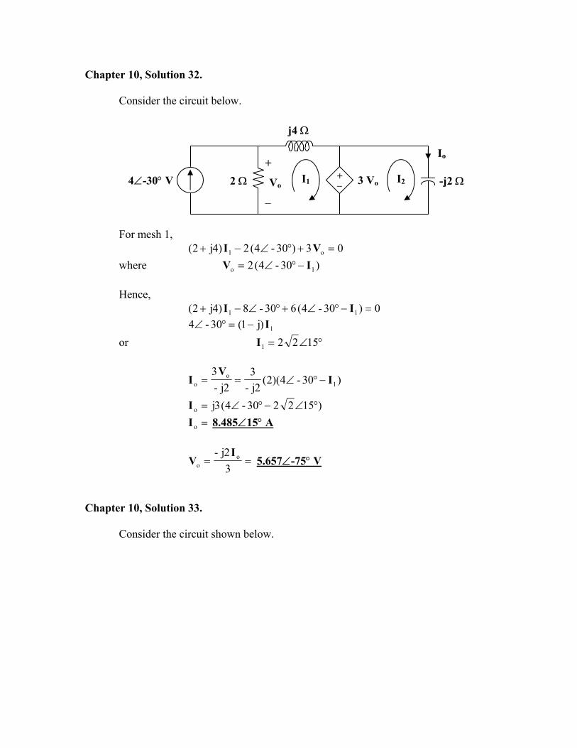
Chapter 10, Solution 32.
Consider the circuit below.
j4 Ω
3 Vo -j2 Ω
Io
I1 I2 + −
+
Vo
−
2 Ω4∠-30° V
For mesh 1,
03)30-4(2)4j2( o1 =+°∠−+ VI where )30-4(2 1o IV −°∠= Hence,
0)30-4(630-8)4j2( 11 =−°∠+°∠−+ II
1)j1(30-4 I−=°∠ or °∠= 15221I
)30-4)(2(2j-
32j-
31
oo I
VI −°∠==
)152230-4(3jo °∠−°∠=I =oI 8.485∠15° A
==32j- o
o
IV 5.657∠-75° V
Chapter 10, Solution 33.
Consider the circuit shown below.
5 A
I1 + −
2 Ω
I
-j2 Ω 2 I I2
I4
I3
j Ω
-j20 V 4 Ω
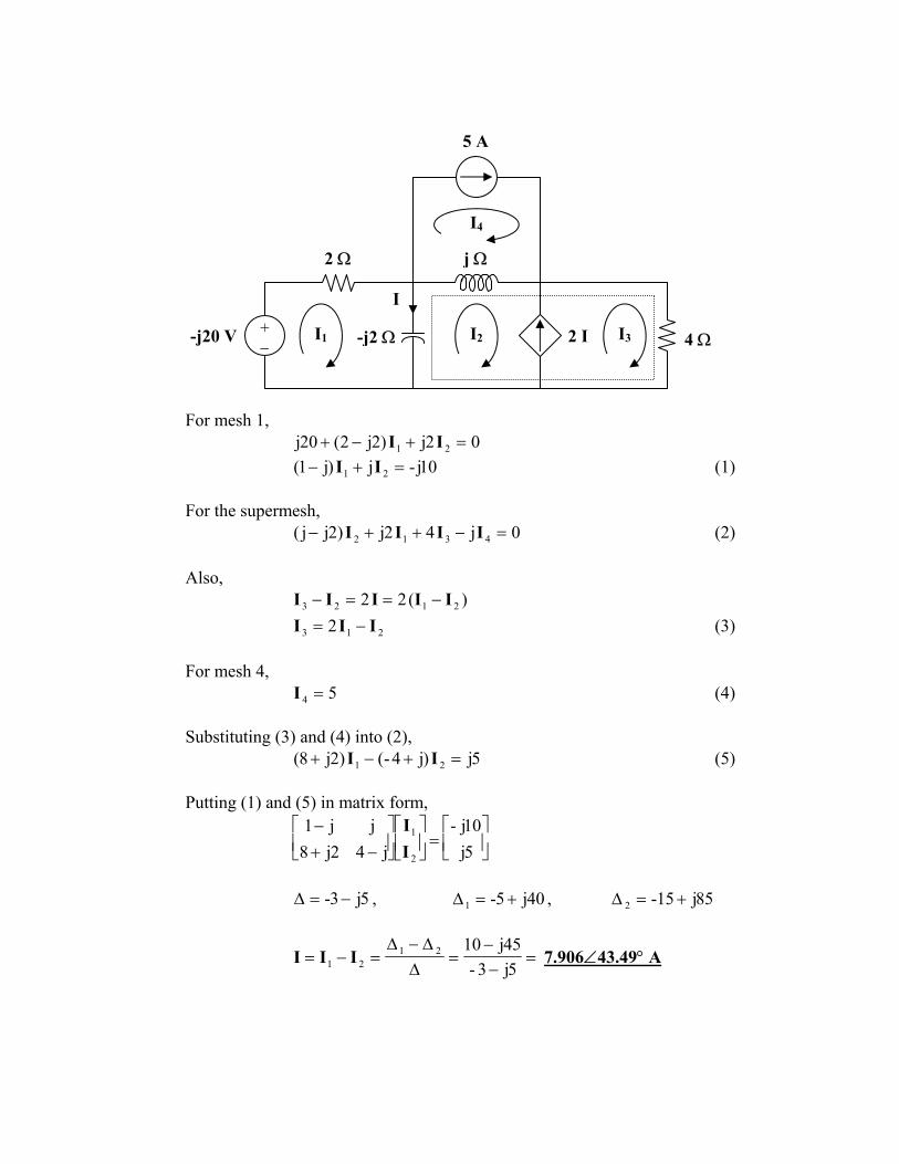
For mesh 1,
02j)2j2(20j 21 =+−+ II 10j-j)j1( 21 =+− II (1)
For the supermesh,
0j42j)2jj( 4312 =−++− IIII (2) Also,
)(22 2123 IIIII −==−
213 2 III −= (3) For mesh 4,
54 =I (4) Substituting (3) and (4) into (2),
5j)j4-()2j8( 21 =+−+ II (5) Putting (1) and (5) in matrix form,
=
−+
−5j10j-
j42j8jj1
2
1
II
5j3- −=∆ , 40j5-1 +=∆ , 85j15-2 +=∆
=−−
=∆∆−∆
=−=5j3-
45j102121 III 7.906∠43.49° A
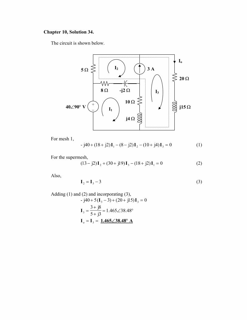
Chapter 10, Solution 34.
The circuit is shown below.
-j2 Ω
j4 Ω
8 Ω
10 Ω
3 A I2
I3
I1+ − 40∠90° V
5 Ω
Io
20 Ω
j15 Ω
For mesh 1,
0)4j10()2j8()2j18(40j- 321 =+−−−++ III (1) For the supermesh,
0)2j18()19j30()2j13( 132 =+−++− III (2) Also,
332 −= II (3) Adding (1) and (2) and incorporating (3),
0)15j20()3(540j- 33 =++−+ II
°∠=++
= 48.38465.13j58j3
3I
== 3o II 1.465∠38.48° A
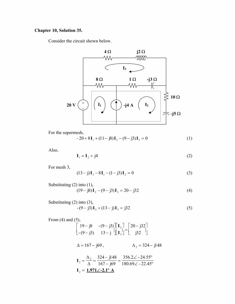
Chapter 10, Solution 35.
Consider the circuit shown below.
4 Ω j2 Ω
1 Ω
I1
I3
I2+ −
-j3 Ω8 Ω
-j4 A
10 Ω
20 V
-j5 Ω
For the supermesh,
0)3j9()8j11(820- 321 =−−−++ III (1) Also,
4j21 += II (2) For mesh 3,
0)3j1(8)j13( 213 =−−−− III (3) Substituting (2) into (1),
32j20)3j9()8j19( 32 −=−−− II (4) Substituting (2) into (3),
32j)j13()3j9(- 32 =−+− II (5) From (4) and (5),
−=
−−−−
32j32j20
j13)3j9(-)3j9(-8j19
3
2
II
69j167 −=∆ , 148j3242 −=∆
°∠°∠
=−−
=∆∆
=45.22-69.18055.24-2.356
69j167148j3242
2I
=2I 1.971∠-2.1° A

Chapter 10, Solution 36.
Consider the circuit below.
j4 Ω -j3 Ω
I1 I2
I3
+
Vo
−
2 Ω2 Ω
+ − 4∠90° A 2 Ω 12∠0° V
2∠0° A
Clearly, 4j9041 =°∠=I and 2-3 =I
For mesh 2, 01222)3j4( 312 =+−−− III
01248j)3j4( 2 =++−− I
64.0j52.3-3j48j16-
2 −=−+
=I
Thus, 28.9j04.7)64.4j52.3)(2()(2 21o +=+=−= IIV
=oV 11.648∠52.82° V Chapter 10, Solution 37. I1 + Ix 120 V Z o90−∠ - I2 Z=80-j35Ω Iz - Iy
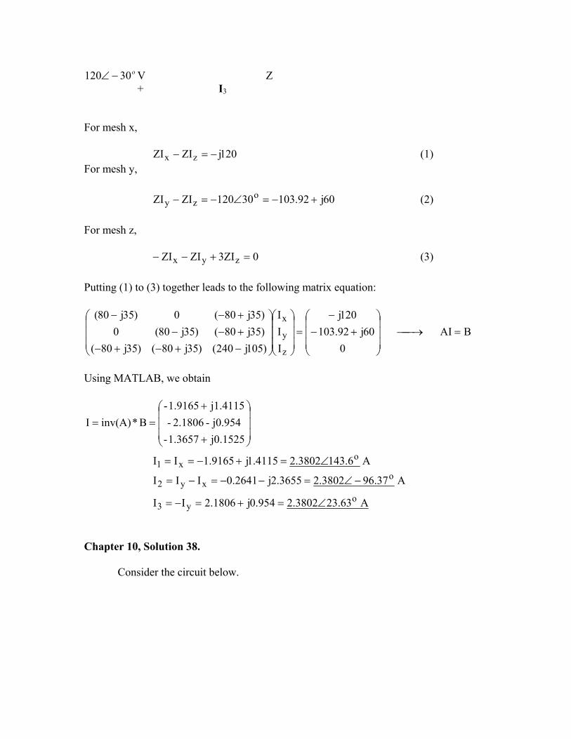
o30120 −∠ V Z + I3 For mesh x,
120jZIZI zx −=− (1) For mesh y,
60j92.10330120ZIZI ozy +−=∠−=− (2)
For mesh z,
0ZI3ZIZI zyx =+−− (3) Putting (1) to (3) together leads to the following matrix equation:
BAI0
60j92.103120j
III
)105j240()35j80()35j80()35j80()35j80(0)35j80(0)35j80(
z
y
x=→
+−
−=
−+−+−+−−+−−
Using MATLAB, we obtain
+
+==
j0.15251.3657-j0.954- 2.1806-j1.4115 1.9165-
B*inv(A)I
A 6.1433802.24115.1j9165.1II ox1 ∠=+−==
A 37.963802.23655.2j2641.0III oxy2 −∠=−−=−=
A 63.233802.2954.0j1806.2II oy3 ∠=+=−=
Chapter 10, Solution 38.
Consider the circuit below.
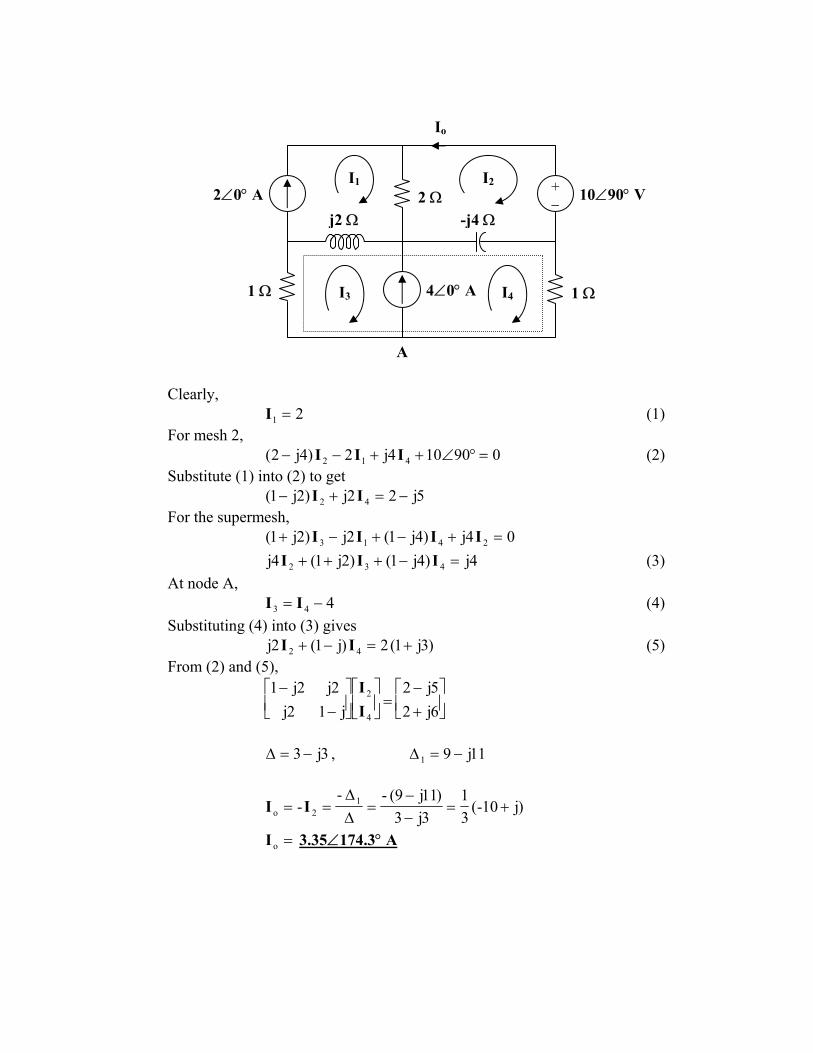
Io
I1
j2 Ω
1 Ω
2 Ω-j4 Ω
10∠90° V
1 Ω
I2
I3 I44∠0° A
+ − 2∠0° A
A
Clearly, 21 =I (1)
For mesh 2, 090104j2)4j2( 412 =°∠++−− III (2)
Substitute (1) into (2) to get 5j22j)2j1( 42 −=+− II
For the supermesh, 04j)4j1(2j)2j1( 2413 =+−+−+ IIII
4j)4j1()2j1(4j 432 =−+++ III (3) At node A,
443 −= II (4) Substituting (4) into (3) gives
)3j1(2)j1(2j 42 +=−+ II (5) From (2) and (5),
+−
=
−
−6j25j2
j12j2j2j1
4
2
II
3j3−=∆ , 11j91 −=∆
)j10-(31
3j3)11j9(--
- 12o +=
−−
=∆∆
== II
=oI 3.35∠174.3° A
Chapter 10, Solution 39.
For mesh 1,
o321 6412I15jI8I)15j28( ∠=+−− (1)
For mesh 2, 0I16jI)9j8(I8 321 =−−+− (2)
For mesh 3, 0I)j10(I16jI15j 321 =++− (3) In matrix form, (1) to (3) can be cast as
BAIor006412
III
)j10(16j15j16j)9j8(8
15j8)15j28( o
3
2
1=
∠=
+−−−−
−−
Using MATLAB, I = inv(A)*B
A 6.1093814.03593.0j128.0I o1 ∠=+−=
A 4.1243443.02841.0j1946.0I o2 ∠=+−=
A 42.601455.01265.0j0718.0I o3 −∠=−=
A 5.481005.00752.0j0666.0III o21x ∠=+=−=
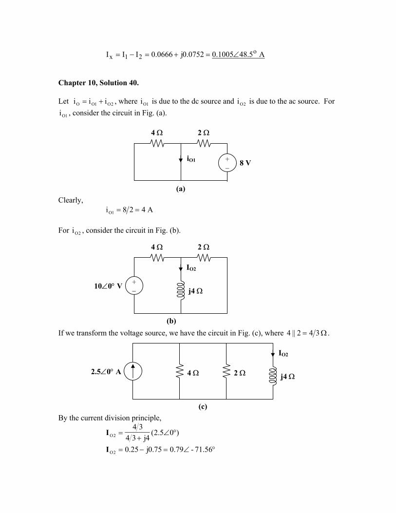
Chapter 10, Solution 40.
Let i , where i is due to the dc source and is due to the ac source. For
, consider the circuit in Fig. (a). 2O1OO ii += 1O 2Oi
1Oi
4 Ω 2 Ω
iO1 + −
8 V
(a)Clearly,
A428i 1O == For , consider the circuit in Fig. (b). 2Oi
4 Ω 2 Ω
10∠0° V j4 Ω
IO2
+ −
(b)If we transform the voltage source, we have the circuit in Fig. (c), where Ω= 342||4 .
2 Ω2.5∠0° A 4 Ω
IO2
j4 Ω
(c) By the current division principle,
)05.2(4j34
342O °∠
+=I
°∠=−= 56.71-79.075.0j25.02OI
Thus, A)56.71t4cos(79.0i 2O °−= Therefore,
=+= 2O1OO iii 4 + 0.79 cos(4t – 71.56°) A
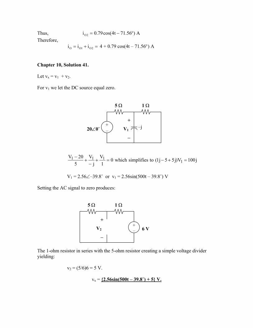
Chapter 10, Solution 41. Let vx = v1 + v2. For v1 we let the DC source equal zero. 5 Ω 1 Ω
j100V)j55j1(tosimplifieswhich01
Vj
V5
20V1
111 =+−=+−
+−
V1 = 2.56∠–39.8˚ or v1 = 2.56sin(500t – 39.8˚) V
Setting the AC signal to zero produces:
+ – 20∠0˚ –j
+
V1
−
1 Ω
+ – 6 V
+
V2
−
5 Ω
The 1-ohm resistor in series with the 5-ohm resistor creating a simple voltage divider yielding: v2 = (5/6)6 = 5 V.
vx = 2.56sin(500t – 39.8˚) + 5 V.
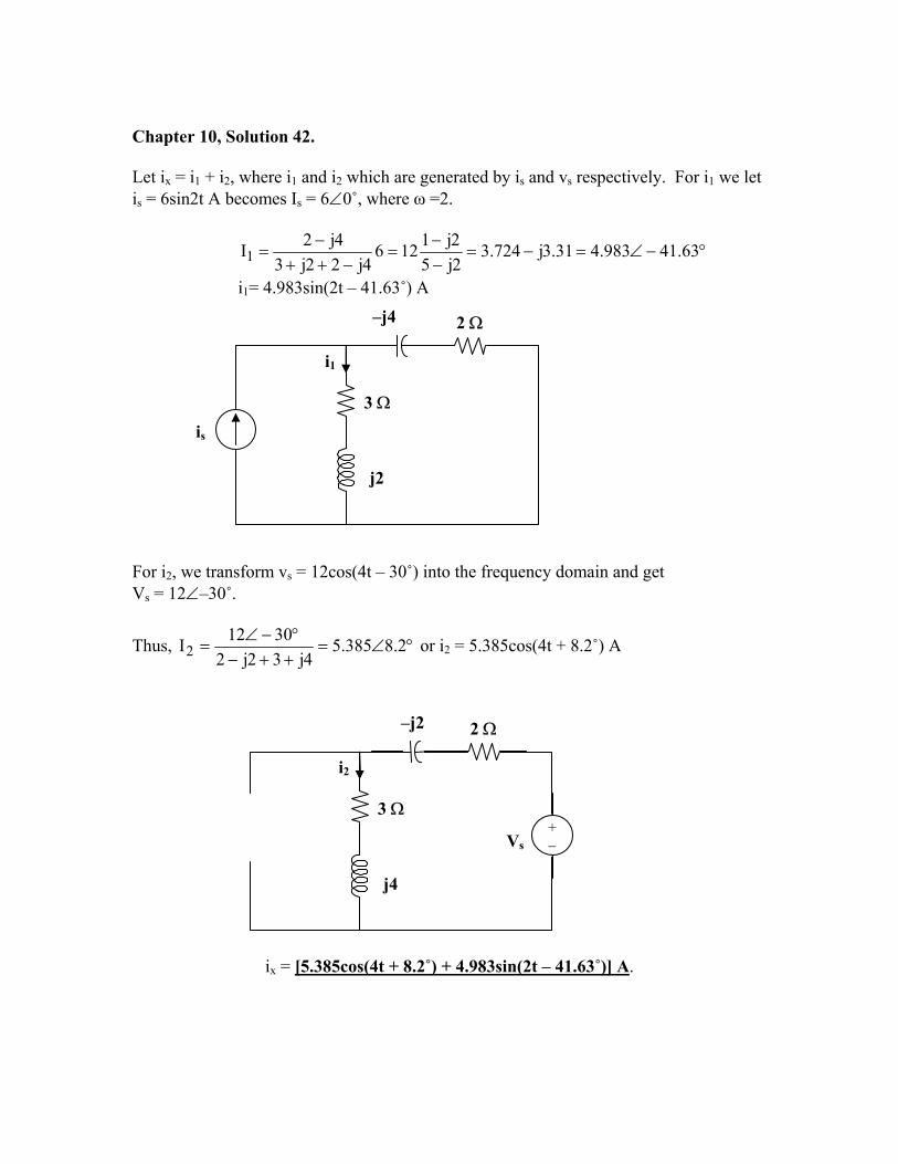
Chapter 10, Solution 42. Let ix = i1 + i2, where i1 and i2 which are generated by is and vs respectively. For i1 we let is = 6sin2t A becomes Is = 6∠0˚, where ω =2.
°−∠=−=−−
=−++
−= 63.41983.431.3j724.3
2j52j1126
4j22j34j2I1
i1= 4.983sin(2t – 41.63˚) A –j4 2 Ω
j2
3 Ω
i1 is For i2, we transform vs = 12cos(4t – 30˚) into the frequency domain and get Vs = 12∠–30˚.
Thus, °∠=++−°−∠
= 2.8385.54j32j2
30122I or i2 = 5.385cos(4t + 8.2˚) A
–j2 2 Ω
+ − Vs
j4
3 Ω
i2
ix = [5.385cos(4t + 8.2˚) + 4.983sin(2t – 41.63˚)] A.
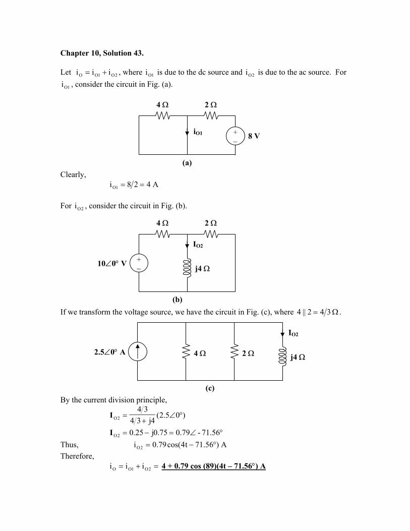
Chapter 10, Solution 43.
Let i , where i is due to the dc source and is due to the ac source. For , consider the circuit in Fig. (a).
2O1OO ii += 1O 2Oi
1Oi
4 Ω 2 Ω
iO1 + −
8 V
(a)Clearly,
A428i 1O == For , consider the circuit in Fig. (b). 2Oi
4 Ω 2 Ω
10∠0° V j4 Ω
IO2
+ −
(b)If we transform the voltage source, we have the circuit in Fig. (c), where Ω= 342||4 .
2 Ω2.5∠0° A 4 Ω
IO2
j4 Ω
(c) By the current division principle,
)05.2(4j34
342O °∠
+=I
°∠=−= 56.71-79.075.0j25.02OI Thus, A)56.71t4cos(79.0i 2O °−= Therefore,
=+= 2O1OO iii 4 + 0.79 cos (89)(4t – 71.56°) A
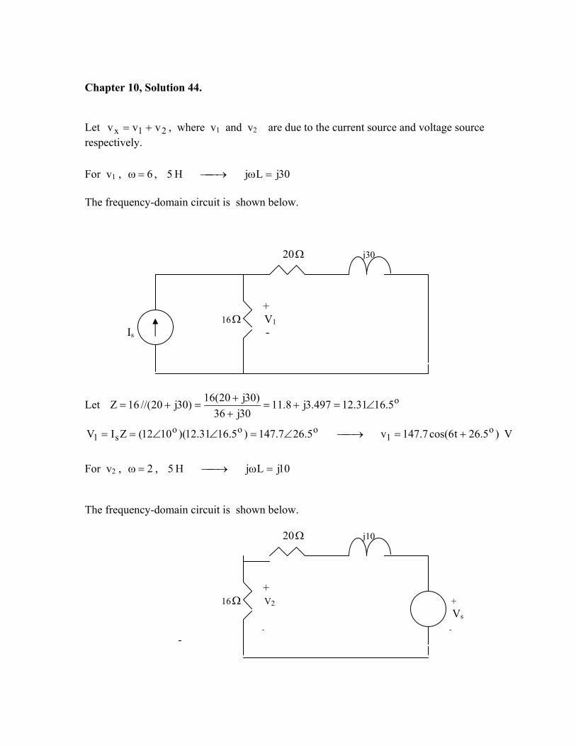
Chapter 10, Solution 44. Let v , where v21x vv += 1 and v2 are due to the current source and voltage source respectively.
For v1 , , 6=ω 30jLjH 5 =ω→ The frequency-domain circuit is shown below. 20Ω j30 + 16Ω V1 Is -
Let o5.1631.12497.3j8.1130j36
)30j20(16)30j20//(16 ∠=+=+
Z +=+=
V )5.26t6cos(7.147v5.267.147)5.1631.12)(1012(ZIV o1
ooos1 +=→∠=∠∠==
For v2 , , 2=ω 10jLjH 5 =ω→ The frequency-domain circuit is shown below. 20Ω j10 + 16Ω V2 + Vs
- - -
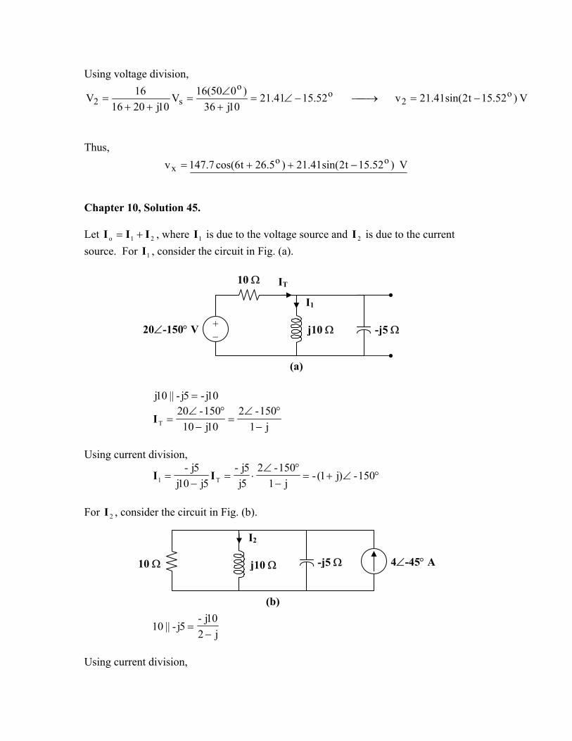
Using voltage division,
V )52.15t2sin(41.21v52.1541.2110j36
)050(16V10j2016
16V o2
oo
s2 −=→−∠=+∠
=++
=
Thus,
V )52.15t2sin(41.21)5.26t6cos(7.147v oox −++=
Chapter 10, Solution 45.
Let I , where I is due to the voltage source and is due to the current source. For I , consider the circuit in Fig. (a).
21o II +=
1
1 2I
10 Ω IT
+ − 20∠-150° V -j5 Ωj10 Ω
I1
(a)
10j-5j-||10j =
j1150-2
10j10150-20
T −°∠
=−
°∠=I
Using current division,
°∠+=−
°∠⋅=
−= 150-)j1(-
j1150-2
5j5j-
5j10j5j-
T1 II
For , consider the circuit in Fig. (b). 2I
-j5 Ωj10 Ω
I2
4∠-45° A 10 Ω
(b)
j210j-
5j-||10−
=
Using current division,
°∠+=°∠+−−
= 45-)j1(2-)45-4(10j)j2(10j-
)j2(10j-2I
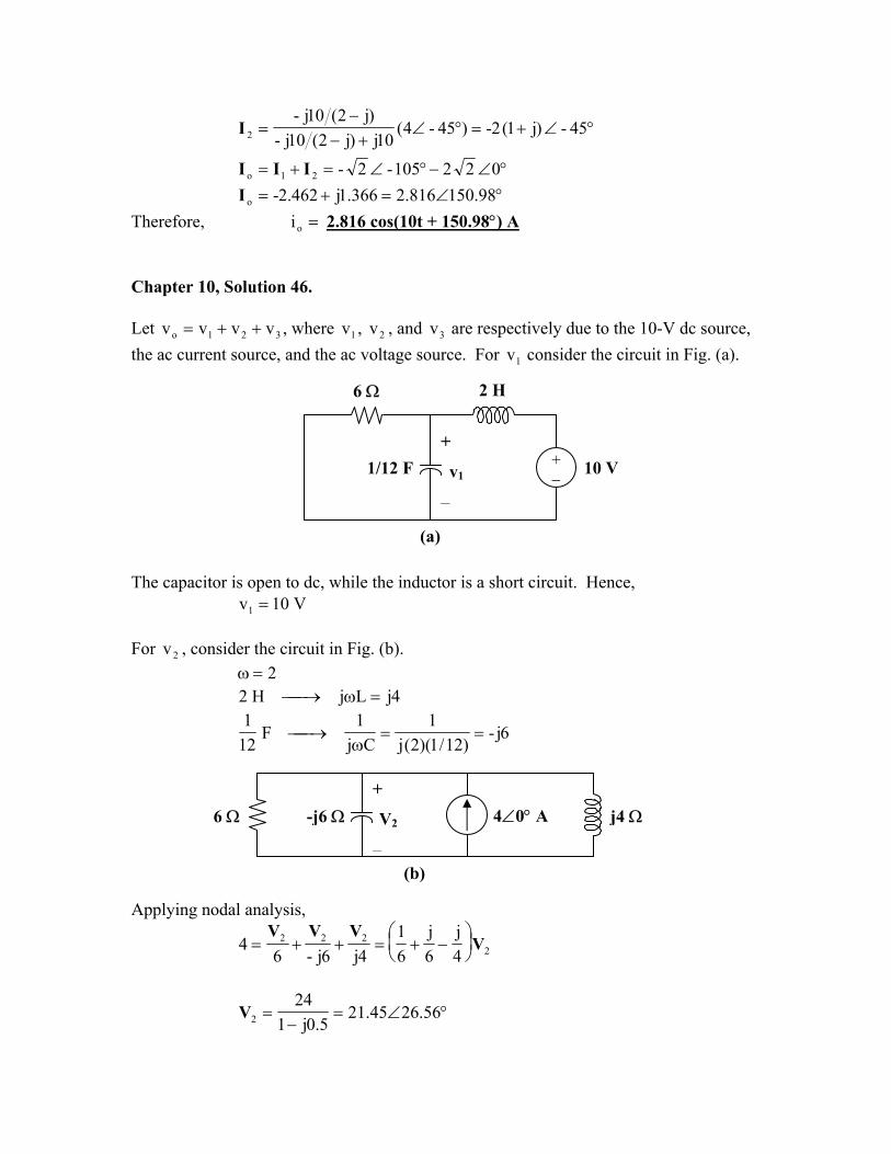
°∠−°∠=+= 022105-2-21o III °∠=+= 98.150816.2366.1j462.2-oI
Therefore, =oi 2.816 cos(10t + 150.98°) A Chapter 10, Solution 46.
Let v , where , , and are respectively due to the 10-V dc source, the ac current source, and the ac voltage source. For consider the circuit in Fig. (a).
321o vvv ++= 1v 2v 3v
1v
2 H 6 Ω
1/12 F + −
+
v1
−
10 V
(a) The capacitor is open to dc, while the inductor is a short circuit. Hence,
V10v1 = For , consider the circuit in Fig. (b). 2v
2=ω 4jLjH2 =ω→
6j-)12/1)(2(j
1Cj
1F
121
==ω
→
4∠0° A+
V2
−
-j6 Ω 6 Ω j4 Ω
(b)
Applying nodal analysis,
2222
4j
6j
61
4j6j-64 V
VVV
−+=++=
°∠=−
= 56.2645.215.0j1
242V
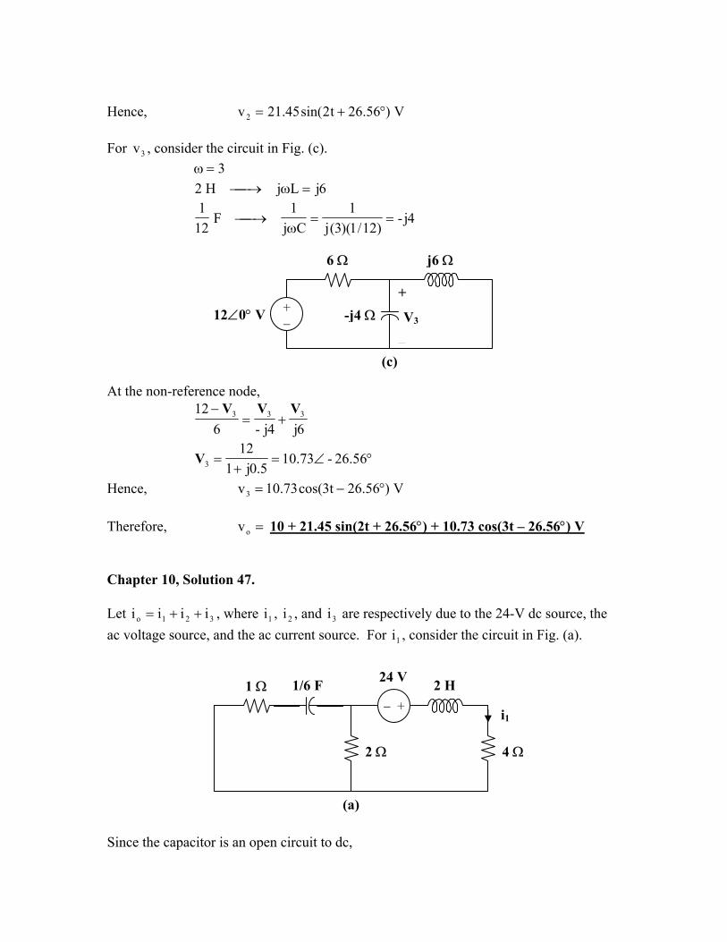
Hence, V)56.26t2sin(45.21v2 °+= For , consider the circuit in Fig. (c). 3v
3=ω 6jLjH2 =ω→
4j-)12/1)(3(j
1Cj
1F
121
==ω
→
6 Ω j6 Ω
+
V3
−
-j4 Ω+ − 12∠0° V
(c)
At the non-reference node,
6j4j-612 333 VVV
+=−
°∠=+
= 56.26-73.105.0j1
123V
Hence, V)56.26t3cos(73.10v3 °−= Therefore, =ov 10 + 21.45 sin(2t + 26.56°) + 10.73 cos(3t – 26.56°) V Chapter 10, Solution 47.
Let i , where i , i , and are respectively due to the 24-V dc source, the ac voltage source, and the ac current source. For , consider the circuit in Fig. (a).
321o iii ++= 1 2 3i
1i
− +
2 Ω
1 Ω 1/6 F 2 H 24 V
i1
4 Ω
(a) Since the capacitor is an open circuit to dc,
A424
24i1 =
+=
For , consider the circuit in Fig. (b). 2i
1=ω 2jLjH2 =ω→
6j-Cj
1F
61
=ω
→
1 Ω j2 Ω-j6 Ω
2 Ω I2I1+ − 10∠-30° V
I2
4 Ω
(b)For mesh 1,
02)6j3(30-10- 21 =−−+°∠ II
21 2)j21(330-10 II −−=°∠ (1)
For mesh 2,
21 )2j6(2-0 II ++=
21 )j3( II += (2)
Substituting (2) into (1)
215j1330-10 I−=°∠ °∠= 1.19504.02I
Hence, A)1.19tsin(504.0i2 °+= For , consider the circuit in Fig. (c). 3i
3=ω 6jLjH2 =ω→
2j-)6/1)(3(j
1Cj
1F
61
==ω
→
1 Ω j6 Ω-j2 Ω
2∠0° A2 Ω
I3
4 Ω
(c)
2j3)2j1(2
)2j1(||2−−
=−
Using current division,
3j13)2j1(2
2j3)2j1(2
6j4
)02(2j3
)2j1(2
3 +−
=
−−
++
°∠⋅−−
=I
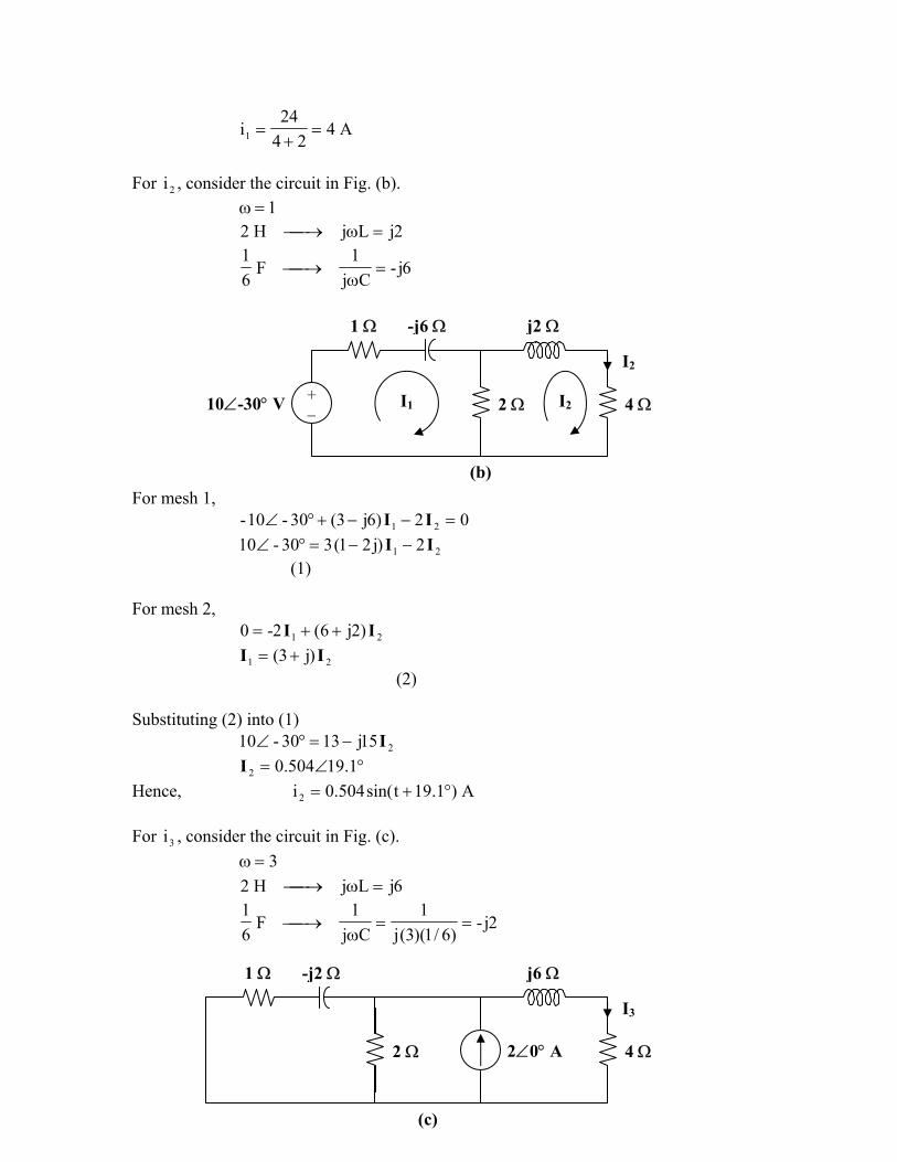
°∠= 43.76-3352.03I Hence A)43.76t3cos(3352.0i3 °−= Therefore, =oi 4 + 0.504 sin(t + 19.1°) + 0.3352 cos(3t – 76.43°) A Chapter 10, Solution 48.
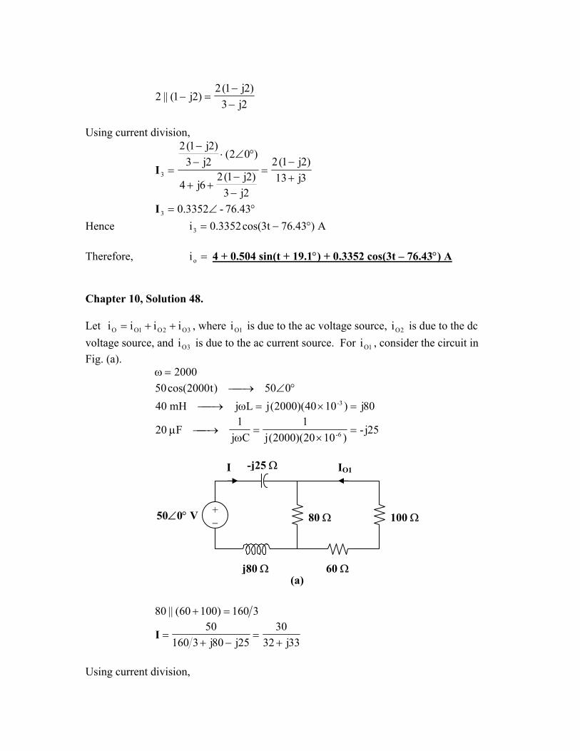
Let i , where i is due to the ac voltage source, is due to the dc voltage source, and is due to the ac current source. For , consider the circuit in Fig. (a).
3O2O1OO iii ++=
3Oi1O 2Oi
1Oi
2000=ω °∠→ 050)t2000cos(50
80j)1040)(2000(jLjmH40 3- =×=ω→
25j-)1020)(2000(j
1Cj
1F20 6- =
×=
ω→µ
I IO1
50∠0° V 80 Ω+ −
-j25 Ω
100 Ω
j80 Ω 60 Ω(a)
3160)10060(||80 =+
33j3230
25j80j316050
+=
−+=I
Using current division,
°∠°∠
==+
=9.4546
1801031-
16080I80-
1O II
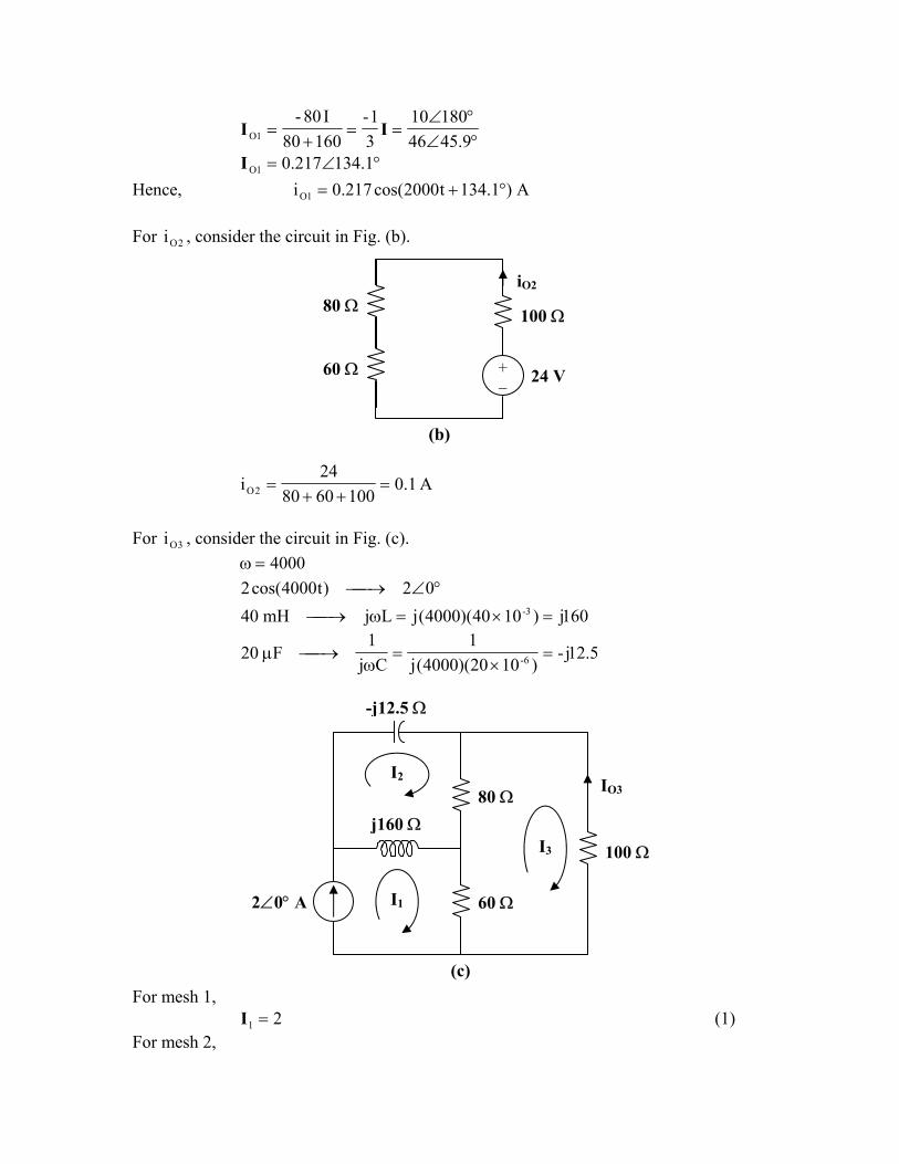
°∠= 1.134217.01OI Hence, A)1.134t2000cos(217.0i 1O °+= For , consider the circuit in Fig. (b). 2Oi
+ −
100 Ω
24 V
iO2
80 Ω
60 Ω
(b)
A1.01006080
24i 2O =
++=
For , consider the circuit in Fig. (c). 3Oi
4000=ω °∠→ 02)t4000cos(2
160j)1040)(4000(jLjmH40 3- =×=ω→
5.12j-)1020)(4000(j
1Cj
1F20 6- =
×=
ω→µ
-j12.5 Ω
80 Ω
60 Ω
I2
I1
I3
2∠0° A
j160 Ω
IO3
100 Ω
(c) For mesh 1,
21 =I (1) For mesh 2,
080160j)5.12j160j80( 312 =−−−+ III Simplifying and substituting (1) into this equation yields
32j8)75.14j8( 32 =−+ II (2) For mesh 3,
08060240 213 =−− III Simplifying and substituting (1) into this equation yields
5.13 32 −= II (3) Substituting (3) into (2) yields
125.54j12)25.44j16( 3 +=+ I
°∠=++
= 38.71782.125.44j16
125.54j123I
°∠== 38.71782.1-- 33O II
Hence, A)38.7t4000sin(1782.1-i 3O °+= Therefore, =Oi 0.1 + 0.217 cos(2000t + 134.1°) – 1.1782 sin(4000t + 7.38°) A Chapter 10, Solution 49.
200,308)30t200sin(8 =ω°∠→°+ j)105)(200(jLjmH5 3- =×=ω→
5j-)101)(200(j
1Cj
1mF1 3- =
×=
ω→
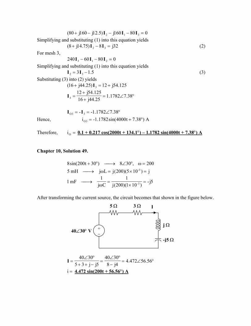
After transforming the current source, the circuit becomes that shown in the figure below.
5 Ω 3 Ω I
+ − 40∠30° V
j Ω
-j5 Ω
°∠=−
°∠=
−++°∠
= 56.56472.44j8
30405jj35
3040I
=i 4.472 sin(200t + 56.56°) A
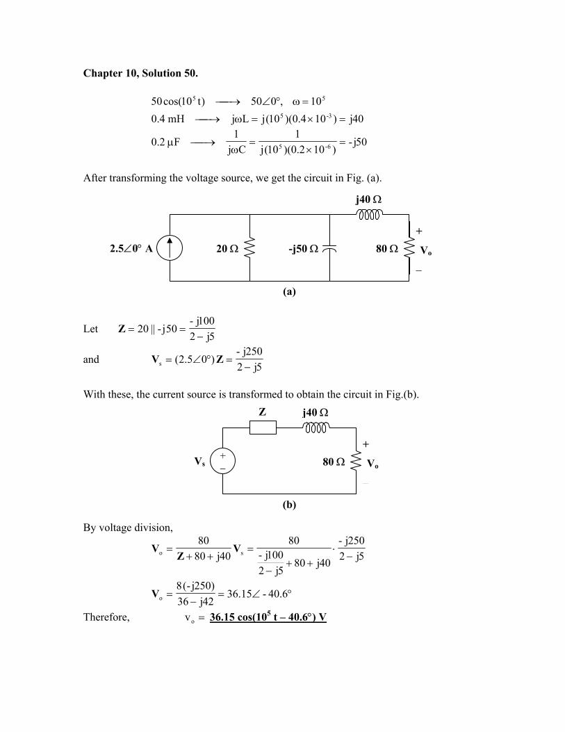
Chapter 10, Solution 50.
55 10,050)t10cos(50 =ω°∠→ 40j)104.0)(10(jLjmH4.0 3-5 =×=ω→
50j-)102.0)(10(j
1Cj
1F2.0 6-5 =
×=
ω→µ
After transforming the voltage source, we get the circuit in Fig. (a).
j40 Ω
20 Ω+
Vo
−
-j50 Ω2.5∠0° A 80 Ω
(a)
Let 5j2
100j-50j-||20
−==Z
and 5j2
250j-)05.2(s −
=°∠= ZV
With these, the current source is transformed to obtain the circuit in Fig.(b).
Z j40 Ω
+
Vo
−
+ − 80 ΩVs
(b)
By voltage division,
5j2250j-
40j805j2
100j-80
40j8080
so −⋅
++−
=++
= VZ
V
°∠=−
= 6.40-15.3642j36
)250j-(8oV
Therefore, =ov 36.15 cos(105 t – 40.6°) V
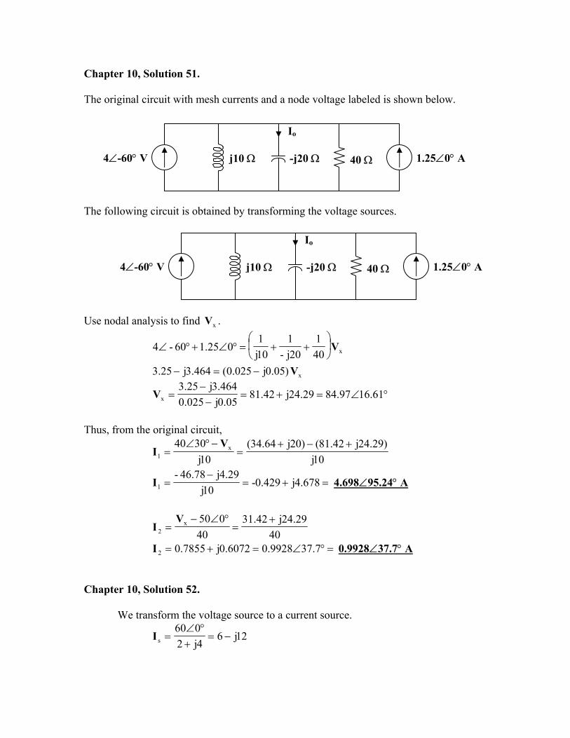
Chapter 10, Solution 51.
The original circuit with mesh currents and a node voltage labeled is shown below.
Io
40 Ωj10 Ω -j20 Ω4∠-60° V 1.25∠0° A
The following circuit is obtained by transforming the voltage sources.
Io
4∠-60° V -j20 Ωj10 Ω 40 Ω 1.25∠0° A
Use nodal analysis to find . xV
x401
20j-1
10j1
025.160-4 V
++=°∠+°∠
x)05.0j025.0(464.3j25.3 V−=−
°∠=+=−−
= 61.1697.8429.24j42.8105.0j025.0
464.3j25.3xV
Thus, from the original circuit,
10j)29.24j42.81()20j64.34(
10j3040 x
1
+−+=
−°∠=
VI
=+=−
= 678.4j429.0-10j
29.4j78.46-1I 4.698∠95.24° A
4029.24j42.31
40050x
2
+=
°∠−=
VI
=°∠=+= 7.379928.06072.0j7855.02I 0.9928∠37.7° A Chapter 10, Solution 52.
We transform the voltage source to a current source.
12j64j2060
s −=+
°∠=I
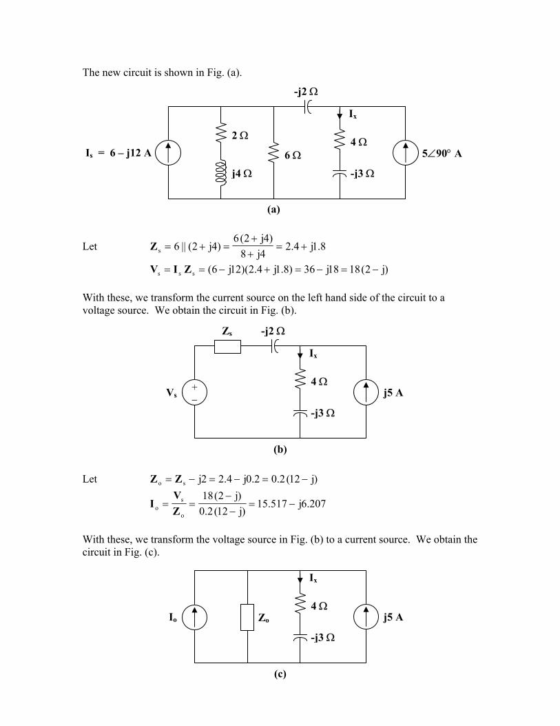
The new circuit is shown in Fig. (a).
-j2 Ω
6 Ω
2 ΩIs = 6 – j12 A
-j3 Ωj4 Ω
4 Ω
Ix
5∠90° A
(a)
Let 8.1j4.24j8
)4j2(6)4j2(||6s +=
++
=+=Z
)j2(1818j36)8.1j4.2)(12j6(sss −=−=+−== ZIV With these, we transform the current source on the left hand side of the circuit to a voltage source. We obtain the circuit in Fig. (b).
Zs -j2 Ω
4 Ω
-j3 Ω
+ −
Vs
Ix
j5 A
(b) Let )j12(2.02.0j4.22jso −=−=−= ZZ
207.6j517.15)j12(2.0
)j2(18
o
so −=
−−
==ZV
I
With these, we transform the voltage source in Fig. (b) to a current source. We obtain the circuit in Fig. (c).
Zo
-j3 Ω
4 Ω
Ix
Io j5 A
(c)
Using current division,
)207.1j517.15(2.3j4.62.0j4.2
)5j(3j4 o
o
ox −
−−
=+−+
= IZ
ZI
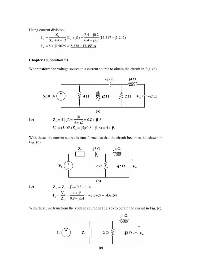
=+= 5625.1j5xI 5.238∠17.35° A Chapter 10, Solution 53.
We transform the voltage source to a current source to obtain the circuit in Fig. (a).
4 Ω j2 Ω+
Vo
−
2 Ω
j4 Ω-j3 Ω
5∠0° A -j2 Ω
(a)
Let 6.1j8.02j4
8j2j||4s +=
+==Z
j4)6.1j8.0)(5()05( ss +=+=°∠= ZV 8 With these, the current source is transformed so that the circuit becomes that shown in Fig. (b).
Zs -j3 Ω j4 Ω
+
Vo
−
+ −
Vs 2 Ω -j2 Ω
(b)Let 4.1j8.03jsx −=−= ZZ
6154.4j0769.34.1j8.0
8j4
s
sx +−=
−+
==ZVI
With these, we transform the voltage source in Fig. (b) to obtain the circuit in Fig. (c).
j4 Ω
+
Vo
−
Zx -j2 Ω2 ΩIx
(c)
Let 5714.0j8571.04.1j8.28.2j6.1
||2 xy −=−−
== ZZ
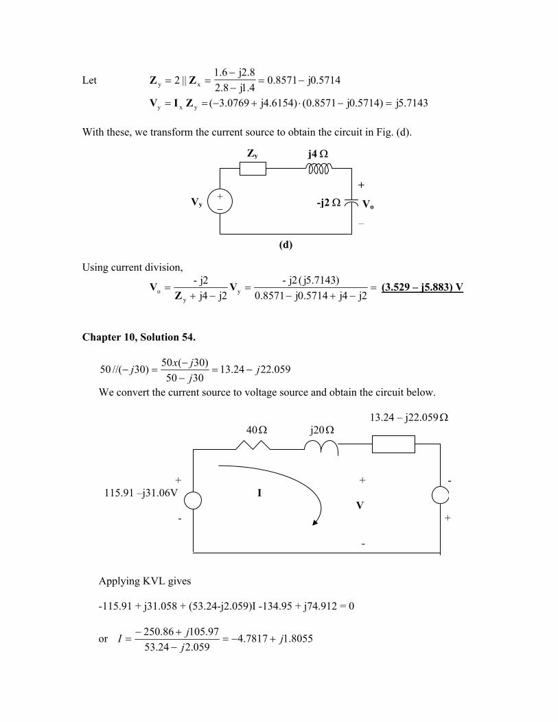
7143.5j)5714.0j8571.0()6154.4j0769.3(yxy =−⋅+−== ZIV With these, we transform the current source to obtain the circuit in Fig. (d).
Zy j4 Ω
+ − -j2 Ω
+
Vo
−
Vy
(d)
Using current division,
=−+−
=−+
=2j4j5714.0j8571.0
)7143.5j(2j-2j4j
2j-y
yo V
ZV (3.529 – j5.883) V
Chapter 10, Solution 54.
059.2224.133050
)30(50)30//(50 jjjxj −=
−−
=−
We convert the current source to voltage source and obtain the circuit below. 13.24 – j22.059Ω
40Ω j20Ω
+ + - 115.91 –j31.06V I V - + -
134.95-j74.912 V
Applying KVL gives -115.91 + j31.058 + (53.24-j2.059)I -134.95 + j74.912 = 0
or 8055.17817.4059.224.53
97.10586.250 jjjI +−=
−+−
=
But I)20j40(VV0VI)20j40(V s +−=→=+++−
V 15406.124)8055.1j7817.4)(20j40(05.31j91.115V o−∠=+−+−−=
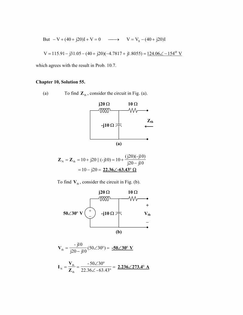
which agrees with the result in Prob. 10.7. Chapter 10, Solution 55.
(a) To find , consider the circuit in Fig. (a). thZ
j20 Ω 10 Ω
Zth-j10 Ω
(a)
10j20j)10j-)(20j(
10)10j-(||20j10thN −+=+== ZZ
=−= 20j10 22.36∠-63.43° Ω To find , consider the circuit in Fig. (b). thV
j20 Ω 10 Ω
+
Vth
−
+ − 50∠30° V -j10 Ω
(b)
=°∠−
= )3050(10j20j
10j-thV -50∠30° V
=°∠
°∠==
43.63-36.223050-
th
thN Z
VI 2.236∠273.4° A
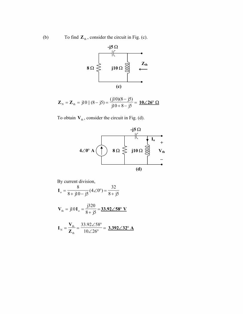
(b) To find , consider the circuit in Fig. (c). thZ
-j5 Ω
j10 ΩZth
8 Ω
(c)
=−+−
=−==5j810j)5j8)(10j(
)5j8(||10jthN ZZ 10∠26° Ω
To obtain , consider the circuit in Fig. (d). thV
-j5 Ω
Io
4∠0° A
+
Vth
−
j10 Ω8 Ω
(d) By current division,
5j832
)04(5j10j8
8o +
=°∠−+
=I
=+
==5j8
320j10j oth IV 33.92∠58° V
=°∠°∠
==2610
5892.33
th
thN Z
VI 3.392∠32° A
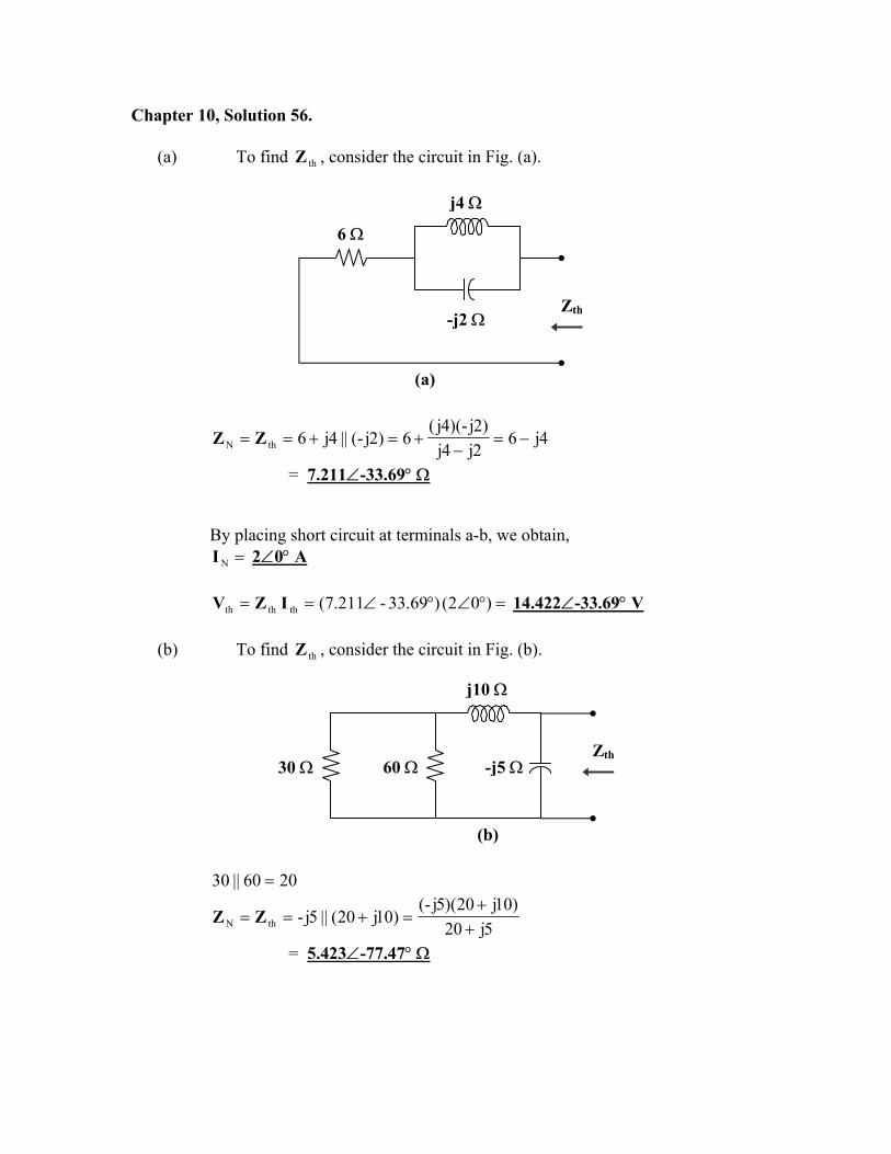
Chapter 10, Solution 56.
(a) To find , consider the circuit in Fig. (a). thZ
j4 Ω
-j2 ΩZth
6 Ω
(a)
4j62j4j
)2j-)(4j(6)2j-(||4j6thN −=
−+=+== ZZ
= 7.211∠-33.69° Ω By placing short circuit at terminals a-b, we obtain,
=NI 2∠0° A
=°∠°∠== )02()69.33-211.7(ththth IZV 14.422∠-33.69° V
(b) To find , consider the circuit in Fig. (b). thZ
j10 Ω
-j5 Ω60 ΩZth
30 Ω
(b)
2060||30 =
5j20)10j20)(5j-(
)10j20(||5j-thN ++
=+== ZZ
= 5.423∠-77.47° Ω
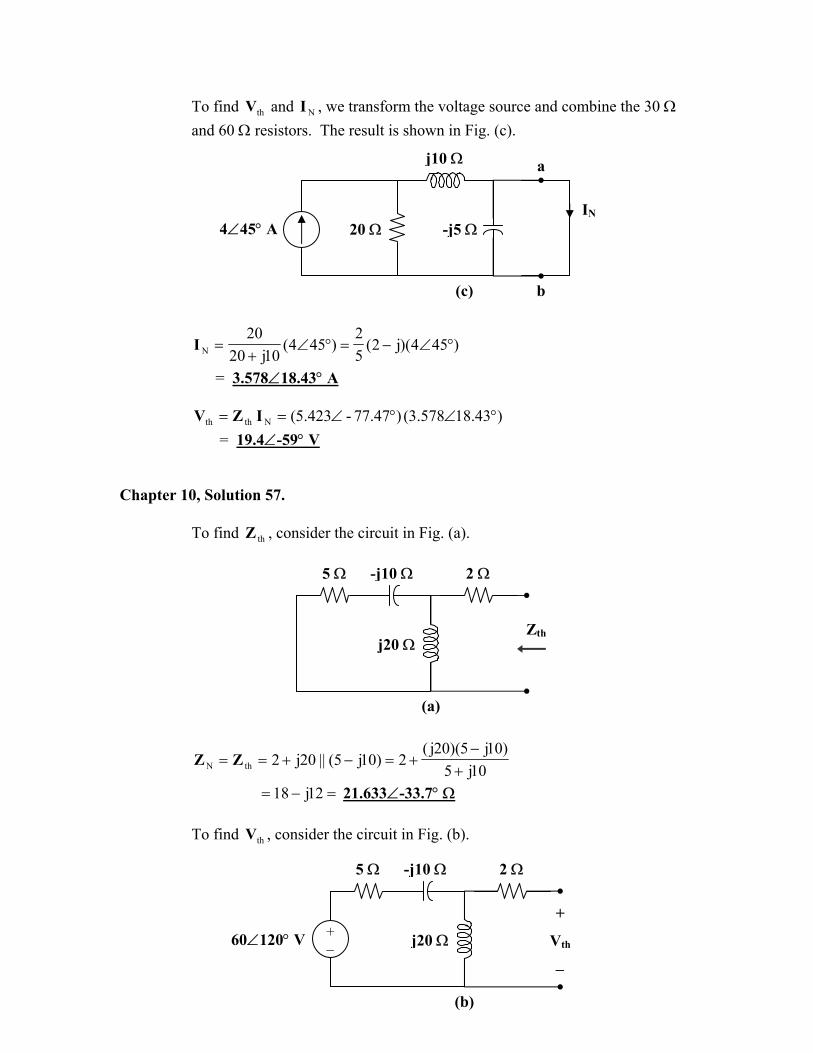
To find and , we transform the voltage source and combine the 30 Ω and 60 Ω resistors. The result is shown in Fig. (c).
thV NI
a
4∠45° A -j5 Ω
j10 Ω
20 ΩIN
b (c)
)454)(j2(52
)454(10j20
20N °∠−=°∠
+=I
= 3.578∠18.43° A
)43.18578.3()47.77-423.5(Nthth °∠°∠== IZV = 19.4∠-59° V
Chapter 10, Solution 57.
To find , consider the circuit in Fig. (a). thZ
5 Ω -j10 Ω 2 Ω
j20 ΩZth
(a)
10j5)10j5)(20j(
2)10j5(||20j2thN +−
+=−+== ZZ
=− 12j18= 21.633∠-33.7° Ω To find , consider the circuit in Fig. (b). thV
5 Ω -j10 Ω 2 Ω
+
Vth
−
+ − j20 Ω60∠120° V
(b)
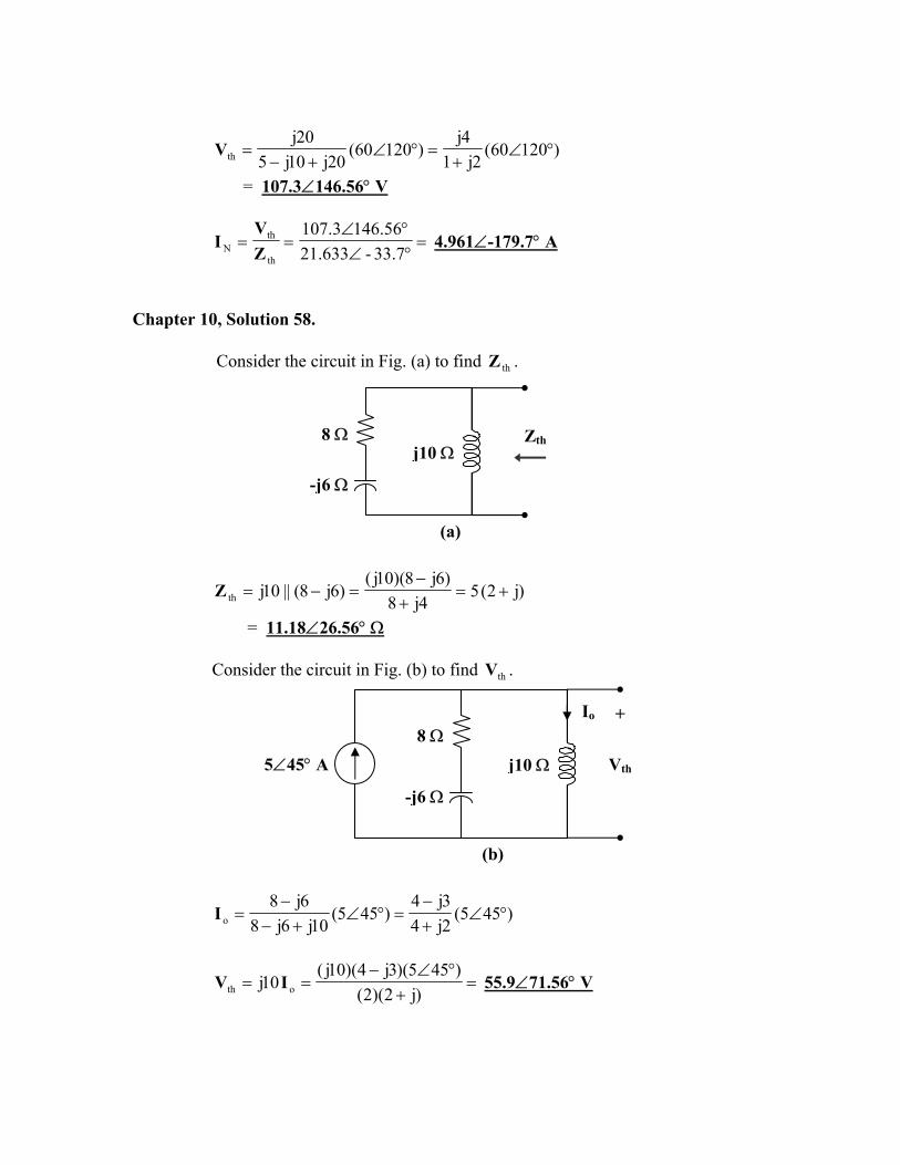
)12060(2j1
4j)12060(
20j10j520j
th °∠+
=°∠+−
=V
= 107.3∠146.56° V
=°∠°∠
==7.33-633.21
56.1463.107
th
thN Z
VI 4.961∠-179.7° A
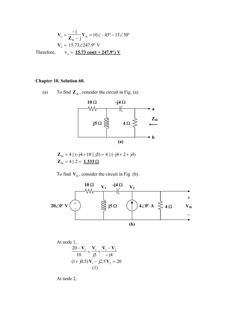
Chapter 10, Solution 58.
Consider the circuit in Fig. (a) to find . thZ
Zth
-j6 Ω
j10 Ω8 Ω
(a)
)j2(54j8
)6j8)(10j()6j8(||10jth +=
+−
=−=Z
= 11.18∠26.56° Ω Consider the circuit in Fig. (b) to find . thV
+
Vth
Io
5∠45° A
-j6 Ω
j10 Ω8 Ω
(b)
)455(2j43j4
)455(10j6j8
6j8o °∠
+−
=°∠+−
−=I
=+
°∠−==
)j2)(2()455)(3j4)(10j(
10j oth IV 55.9∠71.56° V
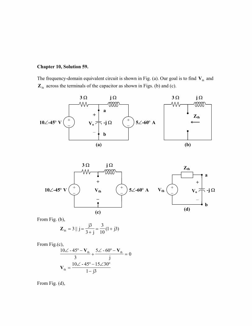
Chapter 10, Solution 59.
The frequency-domain equivalent circuit is shown in Fig. (a). Our goal is to find and
across the terminals of the capacitor as shown in Figs. (b) and (c). thV
thZ
3 Ω j Ω 3 Ω j Ω
Zth
b
a+
Vo
−
-j Ω+ − 5∠-60° A10∠-45° V +
−
(b) (a)
3 Ω j Ω Zth
+
Vth
−
10∠-45° V + −
+ −
+
Vo
−b
a
(d)
+ −
Vth5∠-60° A -j Ω
(c) From Fig. (b),
)3j1(103
j33j
j||3th +=+
==Z
From Fig.(c),
0j
60-53
45-10 thth =−°∠
+−°∠ VV
3j1301545-10
th −°∠−°∠
=V
From Fig. (d),
°∠−°∠=−
= 301545-10j
j-th
tho V
ZV
=oV 15.73∠247.9° V Therefore, =ov 15.73 cos(t + 247.9°) V Chapter 10, Solution 60.
(a) To find , consider the circuit in Fig. (a). thZ
10 Ω -j4 Ω
b
a
j5 Ω 4 Ω
(a)
Zth
)4j24j-(||4)5j||104j-(||4th ++=+=Z
== 2||4thZ 1.333 Ω To find , consider the circuit in Fig. (b). thV
+
Vth
−
j5 Ω 4 Ω
V2V1
+ − 4∠0° A20∠0° V
10 Ω -j4 Ω
(b) At node 1,
4j-5j1020 2111 VVVV −
+=−
205.2j)5.0j1( 21 =−+ VV (1)
At node 2,
44j-4 221 VVV
=−
+
16j)j1( 21 +−= VV (2)
Substituting (2) into (1) leads to
2)3j5.1(16j28 V−=−
333.5j83j5.1
16j282 +=
−−
=V
Therefore,
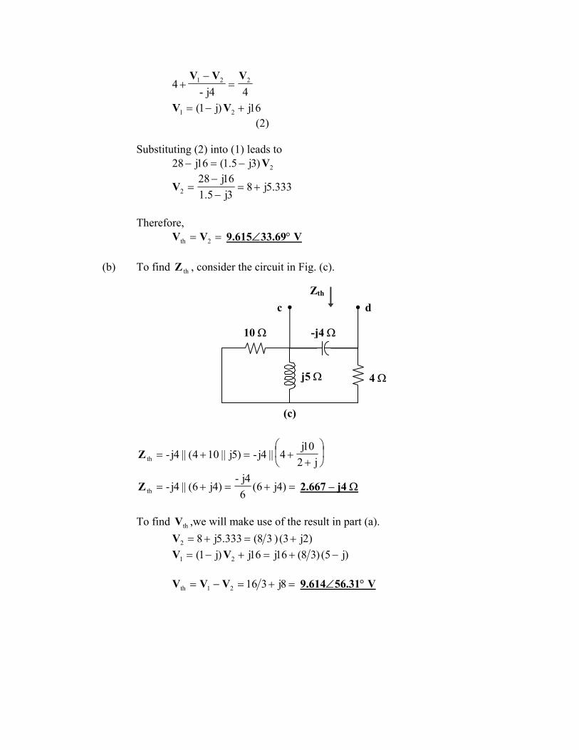
== 2th VV 9.615∠33.69° V
(b) To find , consider the circuit in Fig. (c). thZ
c dZth
j5 Ω 4 Ω
10 Ω -j4 Ω
(c)
+
+=+=j2
10j4||4j-)5j||104(||4j-thZ
=+=+= )4j6(64j-
)4j6(||4j-thZ 2.667 – j4 Ω
To find ,we will make use of the result in part (a). thV
)2j3()38(333.5j82 +=+=V )j5()38(16j16j)j1( 21 −+=+−= VV
=+=−= 8j31621th VVV 9.614∠56.31° V
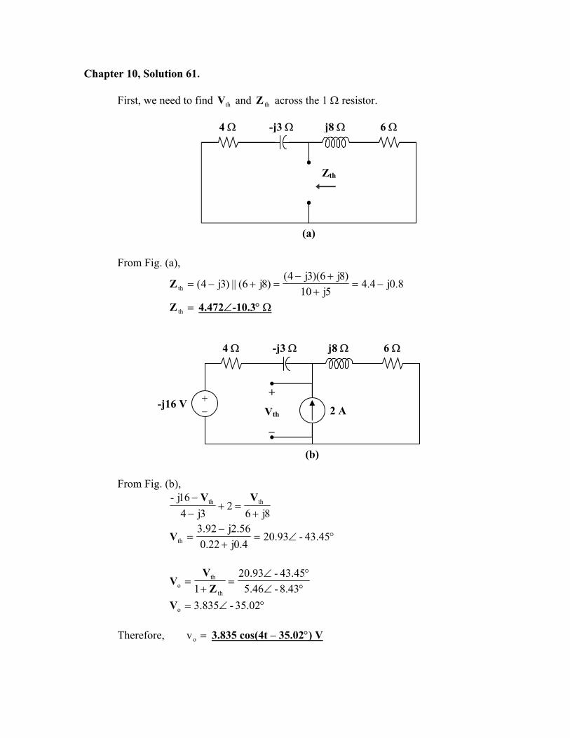
Chapter 10, Solution 61. First, we need to find and across the 1 Ω resistor. thV thZ
4 Ω -j3 Ω j8 Ω 6 Ω
Zth
(a) From Fig. (a),
8.0j4.45j10
)8j6)(3j4()8j6(||)3j4(th −=
++−
=+−=Z
=thZ 4.472∠-10.3° Ω
4 Ω -j3 Ω j8 Ω 6 Ω
+
Vth
−
+ − 2 A -j16 V
(b) From Fig. (b),
8j62
3j416j- thth
+=+
−− VV
°∠=+−
= 45.43-93.204.0j22.056.2j92.3
thV
°∠°∠
=+
=43.8-46.5
45.43-93.201 th
tho Z
VV
°∠= 02.35-835.3oV Therefore, =ov 3.835 cos(4t – 35.02°) V
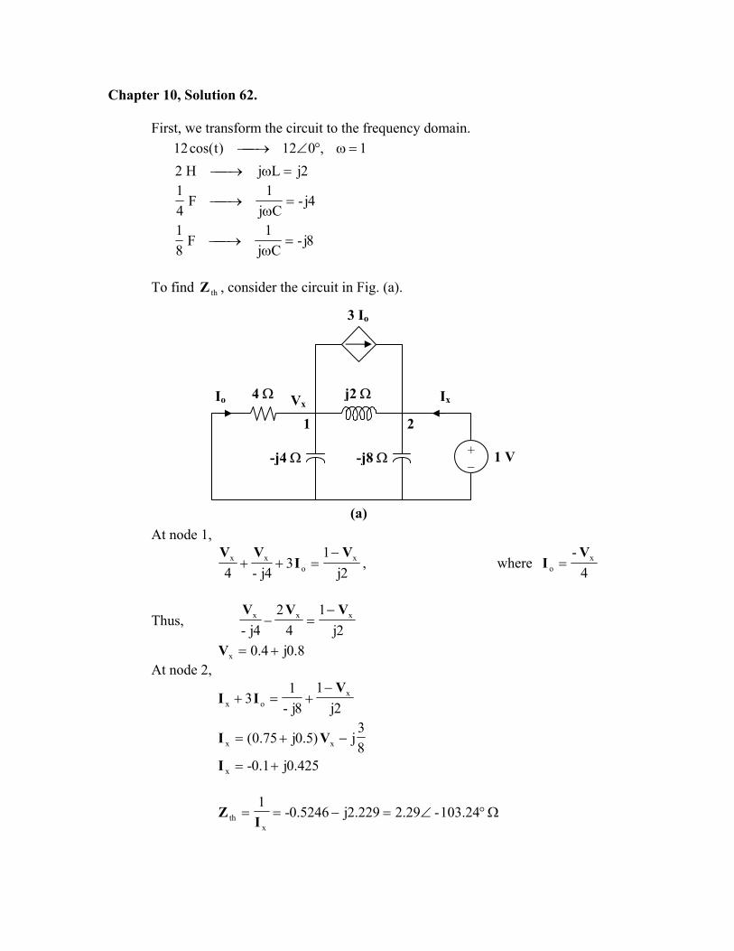
Chapter 10, Solution 62.
First, we transform the circuit to the frequency domain. 1,012)tcos(12 =ω°∠→
2jLjH2 =ω→
4j-Cj
1F
41
=ω
→
8j-Cj
1F
81
=ω
→
To find , consider the circuit in Fig. (a). thZ
3 Io
21
Io 4 Ω
-j8 Ω
Vx
-j4 Ω + −
1 V
j2 Ω Ix
(a)At node 1,
2j1
34j-4
xo
xx VI
VV −=++ , where
4- x
o
VI =
Thus, 2j
14
24j-
xxx VVV −=−
8.0j4.0x +=V At node 2,
2j1
8j-1
3 xox
VII
−+=+
83
j)5.0j75.0( xx −+= VI
425.0j1.0-x +=I
Ω°∠=−== 24.103-29.2229.2j5246.0-1
xth I
Z
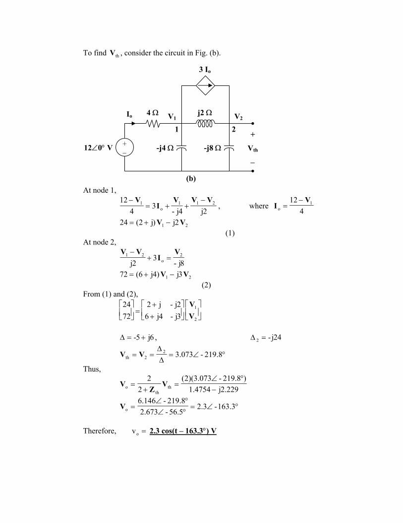
To find , consider the circuit in Fig. (b). thV
3 Io
V2
12∠0° V
Io 4 Ω
-j8 Ω
1 2 +
Vth
−
V1
-j4 Ω+ −
j2 Ω
(b)At node 1,
2j4j-3
412 211
o1 VVV
IV −
++=−
, where 4
12 1o
V−=I
21 2j)j2(24 VV −+= (1)
At node 2,
8j-3
2j2
o21 V
IVV
=+−
21 3j)4j6(72 VV −+= (2)
From (1) and (2),
++
=
2
1
3j-4j62j-j2
7224
VV
6j5- +=∆ , 24j-2 =∆
°∠=∆∆
== 8.219-073.322th VV
Thus,
229.2j4754.1)8.219-073.3)(2(
22
thth
o −°∠
=+
= VZ
V
°∠=°∠°∠
= 3.163-3.25.56-673.28.219-146.6
oV
Therefore, =ov 2.3 cos(t – 163.3°) V
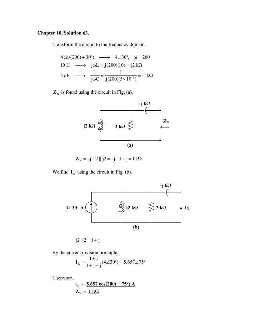
Chapter 10, Solution 63.
Transform the circuit to the frequency domain.
200,304)30t200cos(4 =ω°∠→°+ Ω==ω→ k2j)10)(200(jLjH10
Ω=×
=ω
→µ kj-)105)(200(j
1Cj
1F5 6-
NZ is found using the circuit in Fig. (a).
-j kΩ
2 kΩZN
j2 kΩ
(a)
Ω=++=+= k1j1j-2j||2j-NZ We find using the circuit in Fig. (b). NI
-j kΩ
j2 kΩ 2 kΩ4∠30° A IN
(b)
j12||2j += By the current division principle,
°∠=°∠−+
+= 75657.5)304(
jj1j1
NI
Therefore,
=Ni 5.657 cos(200t + 75°) A =NZ 1 kΩ
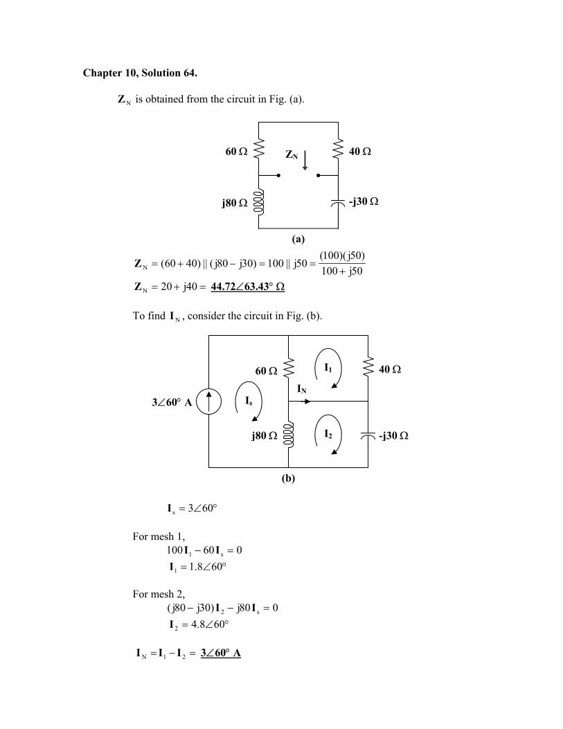
Chapter 10, Solution 64.
is obtained from the circuit in Fig. (a). NZ
ZN60 Ω 40 Ω
-j30 Ωj80 Ω
(a)
50j100)50j)(100(
50j||100)30j80j(||)4060(N +==−+=Z
=+= 40j20NZ 44.72∠63.43° Ω
To find , consider the circuit in Fig. (b). NI
IN
I2
I1
Is3∠60° A
j80 Ω
60 Ω 40 Ω
-j30 Ω
(b)
°∠= 603sI For mesh 1,
060100 s1 =− II °∠= 608.11I
For mesh 2,
080j)30j80j( s2 =−− II °∠= 608.42I
=−= 21N III 3∠60° A
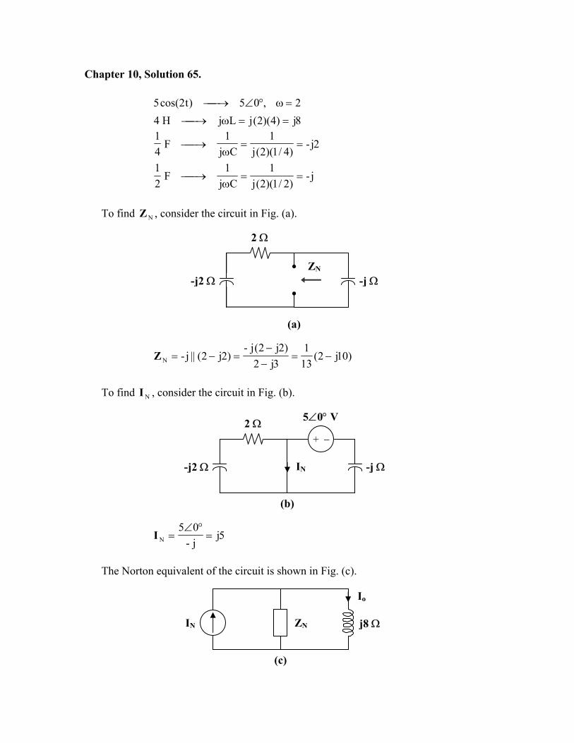
Chapter 10, Solution 65.
2,05)t2cos(5 =ω°∠→ 8j)4)(2(jLjH4 ==ω→
2j-)4/1)(2(j
1Cj
1F
41
==ω
→
j-)2/1)(2(j
1Cj
1F
21
==ω
→
To find , consider the circuit in Fig. (a). NZ
2 Ω
ZN
-j2 Ω -j Ω
(a)
)10j2(131
3j2)2j2(j-
)2j2(||j-N −=−−
=−=Z
To find , consider the circuit in Fig. (b). NI
2 Ω+ −
IN-j2 Ω
5∠0° V
-j Ω
(b)
5jj-05
N =°∠
=I
The Norton equivalent of the circuit is shown in Fig. (c).
Io
ZN IN j8 Ω
(c)
Using current division,
94j210j50
8j)10j2)(131()5j)(10j2)(131(
8j NN
No +
+=
+−−
=+
= IZ
ZI
°∠=−= 47.77-05425294.0j1176.0oI Therefore, =oi 0.542 cos(2t – 77.47°) A
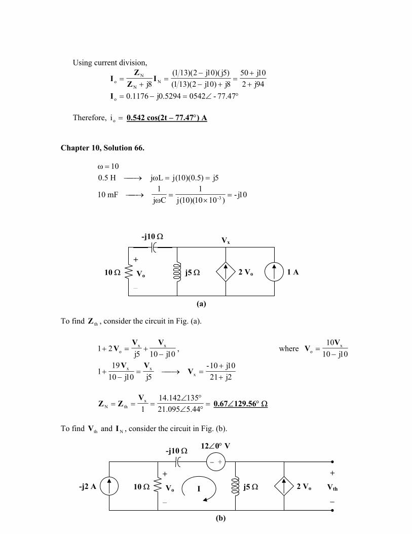
Chapter 10, Solution 66.
ω 10=
5j)5.0)(10(jLjH5.0 ==ω→
10j-)1010)(10(j
1Cj
1mF10 3- =
×=
ω→
Vx
j5 Ω 2 Vo +
Vo
−
-j10 Ω
1 A 10 Ω
(a)
To find , consider the circuit in Fig. (a). thZ
10j105j21 xx
o −+=+
VVV , where
10j10 x
o −V
10=V
2j2110j10-
5j10j1019
1 xxx
++
=→=−
+ VVV
=°∠°∠
===44.5095.21
135142.141
xthN
VZZ 0.67∠129.56° Ω
To find and , consider the circuit in Fig. (b). thV NI
2 Vo I
− ++
Vth
−
+
Vo
−
-j10 Ω
j5 Ω10 Ω
12∠0° V
-j2 A
(b)
012)2(5j)2j-)(10()5j10j10( o =−+−+− VI where )2j-)(10(o IV −= Thus,
20j188-)105j10( −=− I
105j10-20j188
++
=I
200105j)40j21(5j)2(5j oth −=+=+= IIVIV
076.2j802.11-200105j10-
)20j188(105jth +=−
++
=V
=thV 11.97∠170° V
=°∠°∠
==56.12967.0
17097.11
th
thN Z
VI 17.86∠40.44° A
Chapter 10, Solution 67.
Ω+=++
+−−
=++−== 079.1j243.116j20
)6j8(125j23
)5j13(10)6j8//(12)5j13//(10ZZ ThN
Ω+=∠++
=+=∠−
= 37.454j93.25)4560(6j20)6j8(V,44.21j78.13)4560(
5j2310V o
bo
a
A 09.9734.38ZV
I V, 599.11.433VVV o
Th
ThN
obaTh −∠==−∠=−=
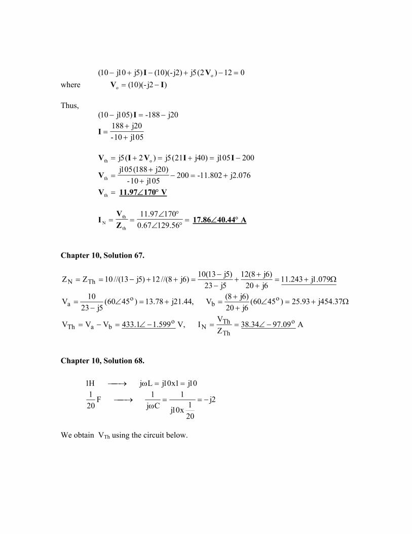
Chapter 10, Solution 68.
10j1x10jLj H1 ==ω→
2j
201x10j
1Cj
1 F201
−==ω
→
We obtain VTh using the circuit below.
Io 4 Ω a + + + -j2 j10 Vo 6<0o Vo/3 - 4Io - - b
5.2j2j10j)2j(10j)2j//(10j −=
−−
=−
ooo I10j)5.2j(xI4V −=−= (1)
0V31I46 oo =++− (2)
Combining (1) and (2) gives
oooTho 19.5052.11
3/10j460jI10jVV,
3/10j46I −∠=
−−
=−==−
=
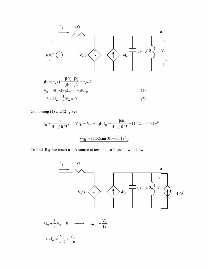
)19.50t10sin(52.11v o
Th −= To find RTh, we insert a 1-A source at terminals a-b, as shown below. Io 4 Ω a + + -j2 j10 Vo Vo/3 - 4Io -
1<0o
12V
I0V31I4 o
ooo −=→=+
10jV
2jV
I41 ooo +
−=+
Combining the two equations leads to
4766.1j2293.14.0j333.0
1Vo −=+
=
Ω−== 477.12293.11
VZ o
Th
Chapter 10, Solution 69.
This is an inverting op amp so that
=ω
==Cj1
R--
i
f
s
o
ZZ
VV
-jωRC
When and ms V=V RC1=ω ,
°∠==⋅⋅⋅= 90-VVj-VRCRC1
j- mmmoV
Therefore,
=°−ω= )90tsin(V)t(v mo - Vm cos(ωt) Chapter 10, Solution 70.
This may also be regarded as an inverting amplifier.
44 104,02)t104cos(2 ×=ω°∠→×
Ω=××
=ω
→ k5.2j-)1010)(104(j
1Cj
1nF10 9-4
i
f
s
o -ZZ
VV
=
where and Ω= k50iZ Ω−
== kj40
100j-)k5.2j-(||k100fZ .
Thus, j40
2j-
s
o
−=
VV
If , °∠= 02sV
°∠=°∠
°∠=
−= 57.88-1.0
43.1-01.4090-4
j404j-
oV
Therefore,
=)t(vo 0.1 cos(4x10⁴ t – 88.57°) V
Chapter 10, Solution 71.
oo 308)30t2cos(8 ∠→+
0. Ω−==ω
→µ−
k1j10x5.0x2j
1Cj
1F5 6
At the inverting terminal,
)j6.0(308)j1.0(Vk2308
k10308V
k1j308V
ooo
oo
o +∠=+→∠
=∠−
+−
∠−
o
o 747.4283.9j1.0
)j6.0)(4j9282.6(V ∠=+
++=
vo(t) = 9.283cos(2t + 4.75o) V
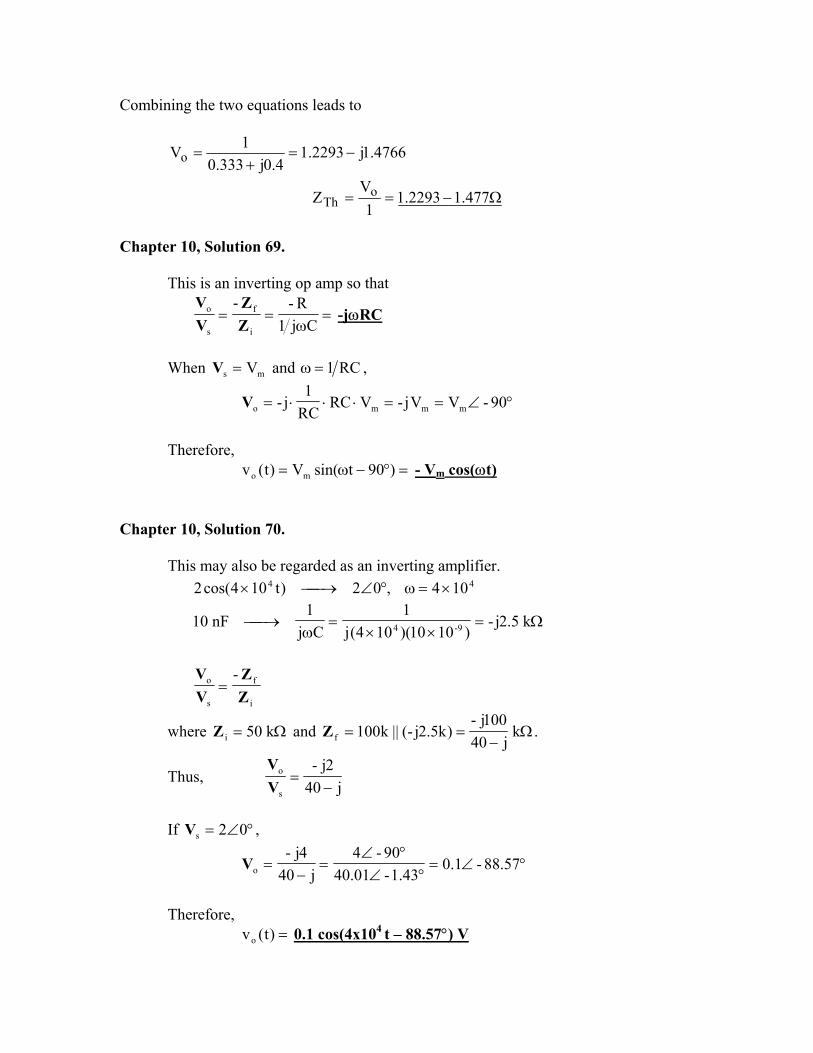
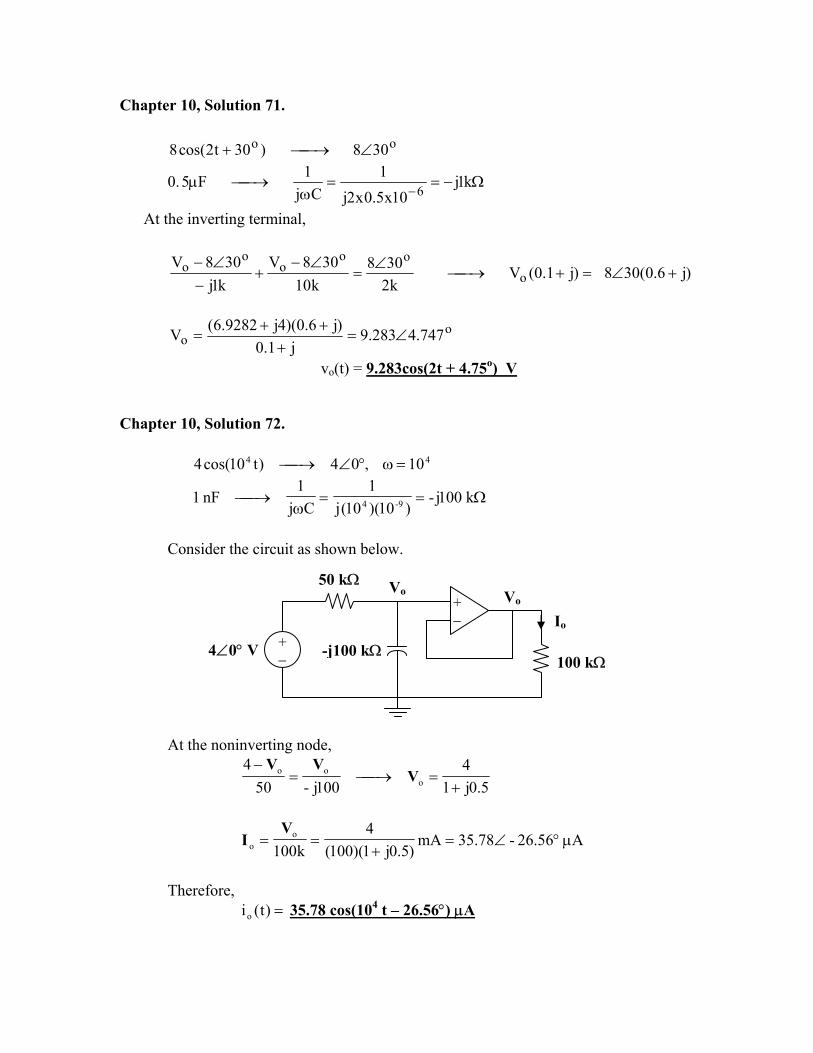
Chapter 10, Solution 72.
44 10,04)t10cos(4 =ω°∠→
Ω==ω
→ k100j-)10)(10(j
1Cj
1nF1 9-4
Consider the circuit as shown below.
4∠0° V
Vo Vo
-j100 kΩ
50 kΩ
+ −
+− Io
100 kΩ
At the noninverting node,
5.0j14
100j-504
ooo
+=→=
−V
VV
A56.26-78.35mA)5.0j1)(100(
4k100
oo µ°∠=
+==
VI
Therefore,
=)t(io 35.78 cos(104 t – 26.56°) µA
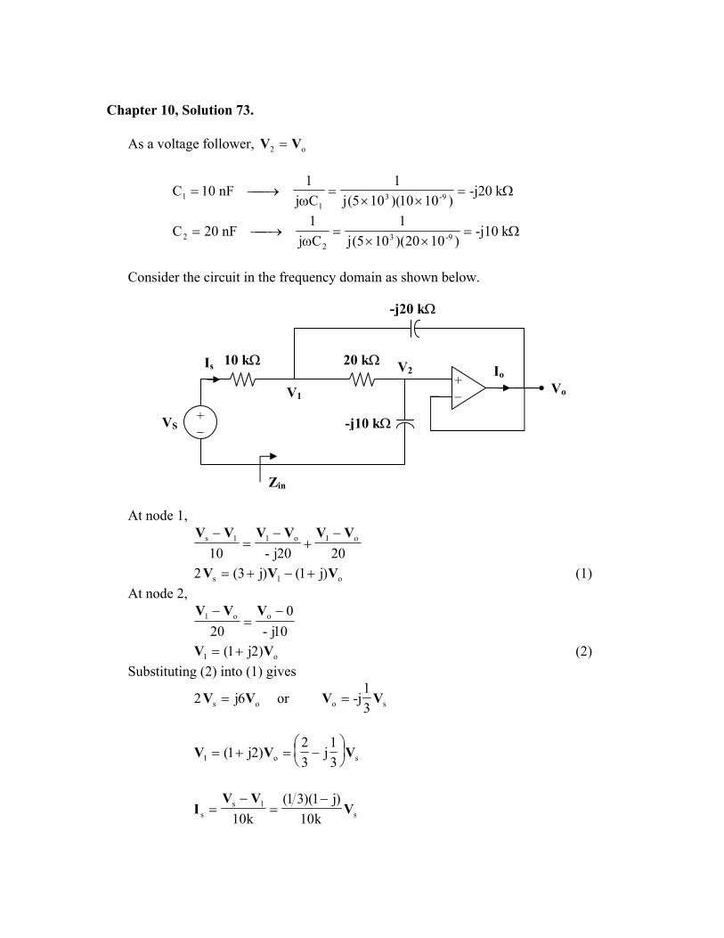
Chapter 10, Solution 73.
As a voltage follower, o2 VV =
Ω=××
=ω
→= k-j20)1010)(105(j
1Cj1
nF10C 9-31
1
Ω=××
=ω
→= k-j10)1020)(105(j
1Cj1
nF20C 9-32
2
Consider the circuit in the frequency domain as shown below.
-j20 kΩ
Zin
Io
V1
V2Is
-j10 kΩ
20 kΩ10 kΩ
+ −
+− Vo
VS
At node 1,
2020j-10o1o11s VVVVVV −
+−
=−
o1s )j1()j3(2 VVV +−+= (1) At node 2,
10j-0
20oo1 −
=− VVV
o1 )2j1( VV += (2) Substituting (2) into (1) gives
os 6j2 VV = or so 31
-j VV =
so1 31
j32
)2j1( VVV
−=+=
s1s
s k10)j1)(31(
k10V
VVI
−=
−=
k30j1
s
s −=
VI
k)j1(15j1
k30
s
sin +=
−==
IV
Z
=inZ 21.21∠45° kΩ Chapter 10, Solution 74.
11i Cj
1R
ω+=Z ,
22f Cj
1R
ω+=Z
=
ω+
ω+
===
11
22
i
f
s
ov
Cj1
R
Cj1
R-ZZ
VV
A
ω+ω+
11
22
2
1
CRj1CRj1
CC
At , 0=ω =vA2
1
CC
As ω , ∞→ =vA1
2
RR
At 11CR
1=ω , =vA
+
+
j1CRCRj1
CC 1122
2
1
At 22CR
1=ω , =vA
++
22112
1
CRCRj1j1
CC
Chapter 10, Solution 75.
3102×=ω
Ω=××
=ω
→== k-j500)101)(102(j
1Cj1
nF1CC 9-31
21
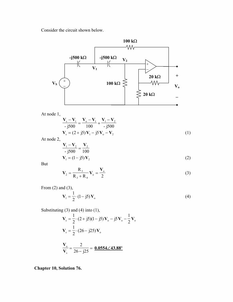
Consider the circuit shown below.
100 kΩ
-j500 kΩ
+
Vo
−
-j500 kΩ
20 kΩ
V1
V2
100 kΩ20 kΩ
+ −
+−
VS
At node 1,
500j-100500j-211o1s VVVVVV −
+−
=−
2o1s 5j)5j2( VVVV −−+= (1) At node 2,
100500j-221 VVV
=−
21 )5j1( VV −= (2) But
2RRR o
o43
32
VVV =
+= (3)
From (2) and (3),
o1 )5j1(21
VV −⋅= (4)
Substituting (3) and (4) into (1),
ooos 21
5j)5j1)(5j2(21
VVVV −−−+⋅=
os )25j26(21
VV −⋅=
=−
=25j26
2
s
o
VV
0.0554∠43.88°
Chapter 10, Solution 76.
Let the voltage between the -jkΩ capacitor and the 10kΩ resistor be V1.
o1o
o1o11o
V6.0jV)6.0j1(302
k20VV
k10VV
k4jV302
+−=∠
→−
+−
=−
−∠ (1)
Also,
o1oo1 V)5j1(Vk2j
Vk10VV
+=→−
=−
(2)
Solving (2) into (1) yields
V 34.813123.03088.0j047.0V oo −∠=−=
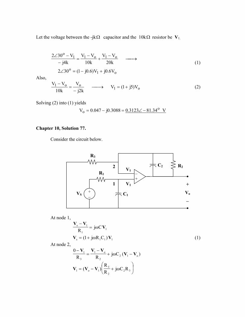
Chapter 10, Solution 77.
Consider the circuit below.
1
2
+ −
VS
+
Vo
−
C1
C2 R2 R1
V1
V1
R3
−+
At node 1,
11
1s CjR
VVV
ω=−
111s )CRj1( VV ω+= (1) At node 2,
)(CjRR
0o12
2
o1
3
1 VVVVV
−ω+−
=−
ω+−= 32
2
31o1 RCj
RR
)( VVV
13223
o RCj)RR(1
1 VV
ω++= (2)
From (1) and (2),
ω++
ω+=
3223
2
11
so RRCjR
R1
CRj1V
V
=s
o
VV
)RRCjR()CRj1(RRCjRR
322311
32232
ω+ω+ω++
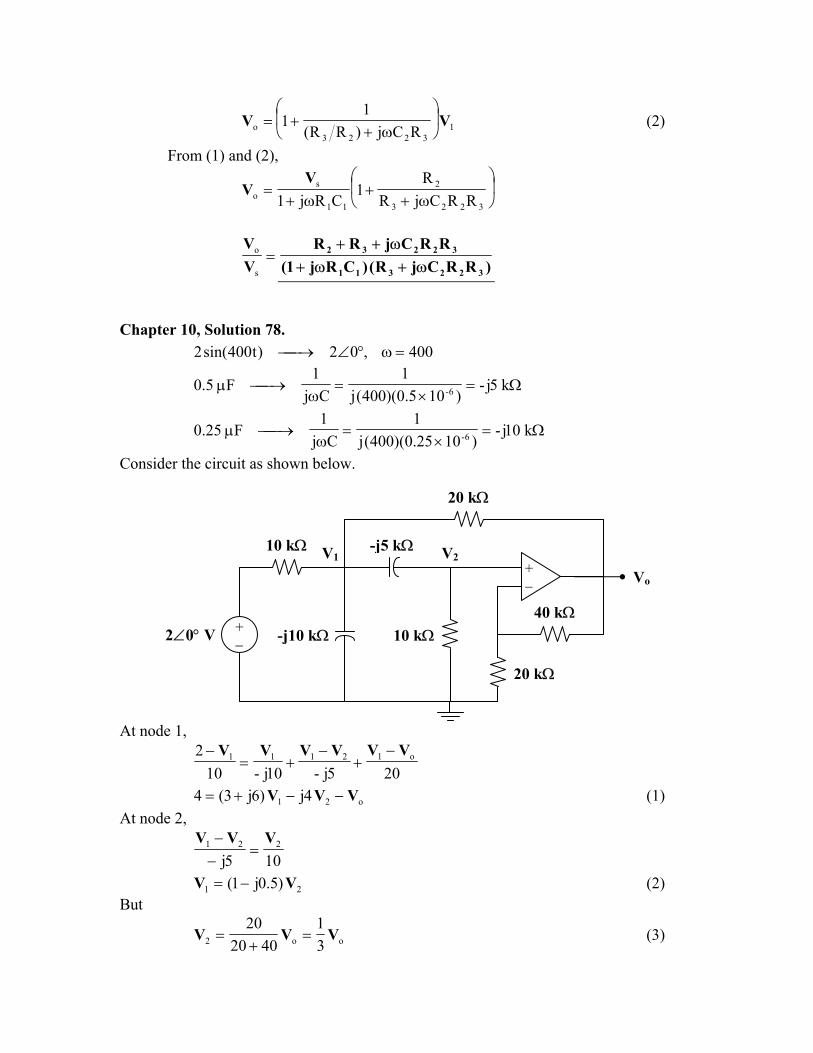
Chapter 10, Solution 78. 400,02)t400sin(2 =ω°∠→
Ω=×
=ω
→µ k5j-)105.0)(400(j
1Cj
1F5.0 6-
Ω=×
=ω
→µ k10j-)1025.0)(400(j
1Cj
1F25.0 6-
Consider the circuit as shown below.
20 kΩ
At node 1,
10 kΩ2∠0° V
10 kΩ -j5 kΩ
20 kΩ
V1 V2
-j10 kΩ40 kΩ
+ −
+− Vo
205j-10j-102 o12111 VVVVVV −
+−
+=−
o21 4j)6j3(4 VVV −−+= (1) At node 2,
105j221 VVV
=−−
21 )5.0j1( VV −= (2) But
oo2 31
402020
VVV =+
= (3)
From (2) and (3),
o1 )5.0j1(31
VV −⋅= (4)
Substituting (3) and (4) into (1) gives
oooo 61
j134
j)5.0j1(31
)6j3(4 VVVV
−=−−−⋅⋅+=
°∠=−
= 46.9945.3j6
24oV
Therefore, =)t(vo 3.945 sin(400t + 9.46°) V
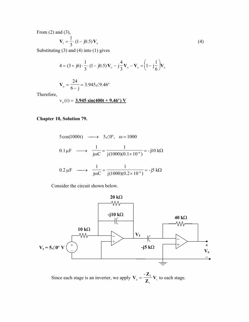
Chapter 10, Solution 79.
1000,05)t1000cos(5 =ω°∠→
Ω=×
=ω
→µ k10j-)101.0)(1000(j
1Cj
1F1.0 6-
Ω=×
=ω
→µ k5j-)102.0)(1000(j
1Cj
1F2.0 6-
Consider the circuit shown below.
20 kΩ
+ − Vs = 5∠0° V
V1
-j5 kΩ
-j10 kΩ 40 kΩ
+Vo−
− +
10 kΩ −+
Since each stage is an inverter, we apply ii
fo
-V
ZZ
V = to each stage.
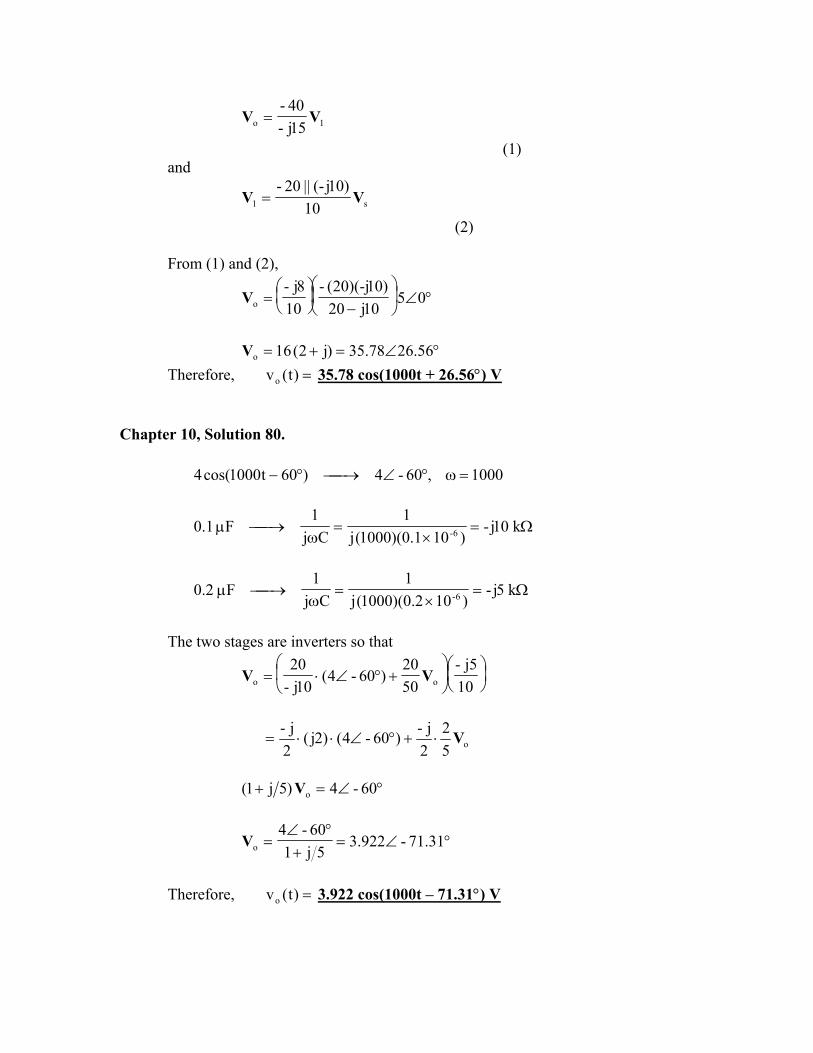
1o 15j-40-
VV =
(1) and
s1 10)10j-(||20-
VV =
(2) From (1) and (2),
°∠
−
= 0510j20
)10-j)(20(-10
8j-oV
°∠=+= 56.2678.35)j2(16oV
Therefore, =)t(vo 35.78 cos(1000t + 26.56°) V Chapter 10, Solution 80. 4
1000,60-4)60t1000cos( =ω°∠→°−
Ω=×
=ω
→µ k10j-)101.0)(1000(j
1Cj
1F1.0 6-
Ω=×
=ω
→µ k5j-)102.0)(1000(j
1Cj
1F2.0 6-
The two stages are inverters so that
+°∠⋅=
10j5-
5020
)60-4(10j-
20oo VV
o52
2j-)60-4()2j(
2j- V⋅+°∠⋅⋅=
°∠=+ 60-4)5j1( oV
°∠=+
°∠= 31.71-922.3
5j160-4
oV
Therefore, =)t(vo 3.922 cos(1000t – 71.31°) V
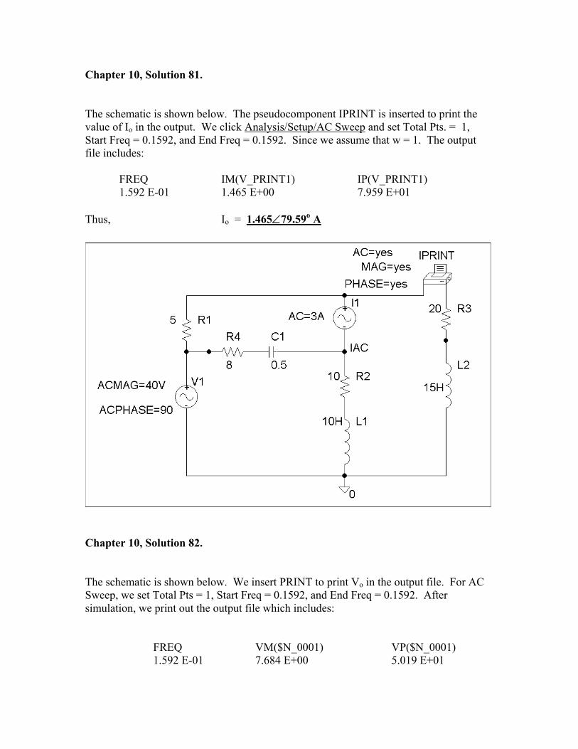
Chapter 10, Solution 81. The schematic is shown below. The pseudocomponent IPRINT is inserted to print the value of Io in the output. We click Analysis/Setup/AC Sweep and set Total Pts. = 1, Start Freq = 0.1592, and End Freq = 0.1592. Since we assume that w = 1. The output file includes: FREQ IM(V_PRINT1) IP(V_PRINT1) 1.592 E-01 1.465 E+00 7.959 E+01 Thus, Io = 1.465∠79.59o A
Chapter 10, Solution 82. The schematic is shown below. We insert PRINT to print Vo in the output file. For AC Sweep, we set Total Pts = 1, Start Freq = 0.1592, and End Freq = 0.1592. After simulation, we print out the output file which includes: FREQ VM($N_0001) VP($N_0001) 1.592 E-01 7.684 E+00 5.019 E+01
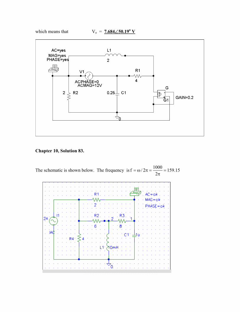
which means that Vo = 7.684∠50.19o V
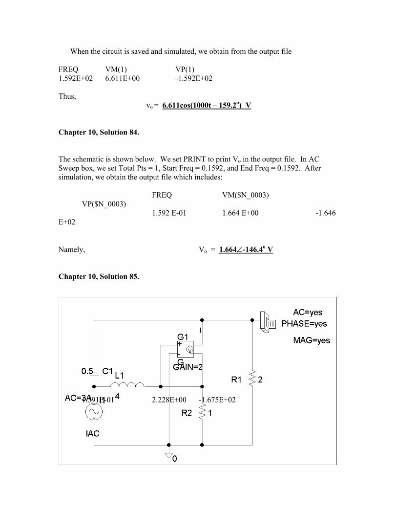
hapter 10, Solution 83.
he schematic is shown below. The frequency is
C
T 15.1592
10002/f =π
=πω=
When the circuit is saved and simulated, we obtain from the output file
REQ VM(1) VP(1)
hus, vo = 6.611cos(1000t – 159.2o) V
F1.592E+02 6.611E+00 -1.592E+02 T
hapter 10, Solution 84.
he schematic is shown below. We set PRINT to print Vo in the output file. In AC
FREQ VM($N_0003)
1.592 E-01 1.664 E+00 -1.646
amely, Vo = 1.664∠-146.4o V
C TSweep box, we set Total Pts = 1, Start Freq = 0.1592, and End Freq = 0.1592. After simulation, we obtain the output file which includes: VP($N_0003) E+02 N
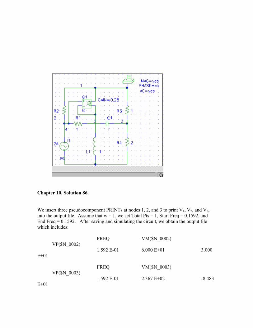
hapter 10, Solution 85.
C
The schematic is shown below. We let =ω rad/s so that L=1H and C=1F.
When the circuit is saved and simulated, we obtain from the output file
FREQ VM(1) VP(1)
From this, we conclude that
5.167228.2Vo −∠= V
1
1.591E-01 2.228E+00 -1.675E+02
Chapter 10, Solution 86.
e insert three pseudocomponent PRINTs at nodes 1, 2, and 3 to print V1, V2, and V3,
FREQ VM($N_0002)
1.592 E-01 6.000 E+01 3.000
FREQ VM($N_0003)
1.592 E-01 2.367 E+02 -8.483
Winto the output file. Assume that w = 1, we set Total Pts = 1, Start Freq = 0.1592, and End Freq = 0.1592. After saving and simulating the circuit, we obtain the output file which includes: VP($N_0002) E+01 VP($N_0003) E+01
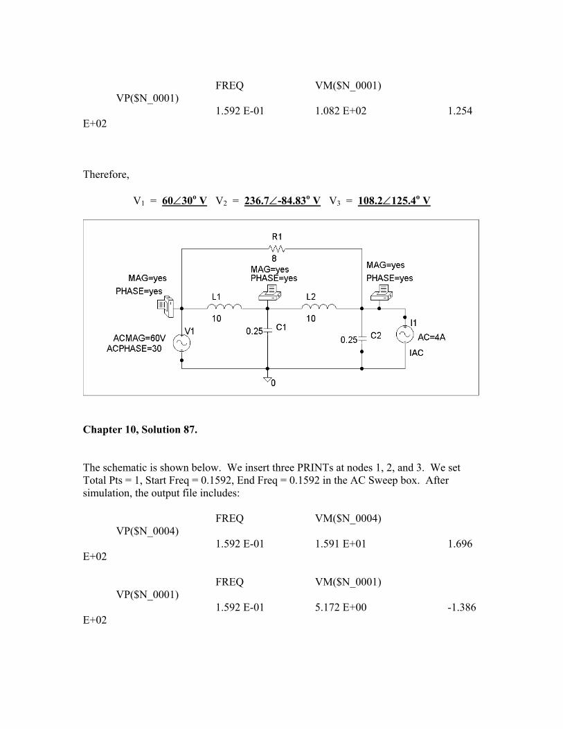
FREQ VM($N_0001)
1.592 E-01 1.082 E+02 1.254
herefore,
V1 = 60∠30o V
VP($N_0001) E+02 T
V2 = 236.7∠-84.83o V V3 = 108.2∠125.4o V
hapter 10, Solution 87.
he schematic is shown below. We insert three PRINTs at nodes 1, 2, and 3. We set otal Pts = 1, Start Freq = 0.1592, End Freq = 0.1592 in the AC Sweep box. After
VM($N_0004) VP($N_0004)
1.696
FREQ VM($N_0001) VP($N_0001)
-1.386
C TTsimulation, the output file includes: FREQ 1.592 E-01 1.591 E+01 E+02 1.592 E-01 5.172 E+00 E+02
FREQ VM($N_0003) VP($N_0003)
-1.524
ore,
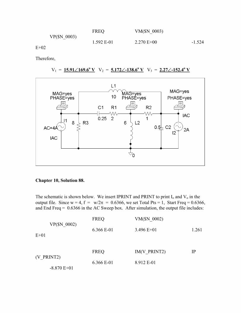
∠ o V
1.592 E-01 2.270 E+00 E+02 Theref
V1 = 15.91 169.6 V2 = 5.172∠-138.6o V V3 = 2.27∠-152.4o V
hapter 10, Solution 88.
ow. We insert IPRINT and PRINT to print Io and Vo in the utput file. Since w = 4, f = w/2π = 0.6366, we set Total Pts = 1, Start Freq = 0.6366, nd End Freq = 0.6366 in the AC Sweep box. After simulation, the output file includes:
6.366 E-01 3.496 E+01 1.261
FREQ IM(V_PRINT2) IP _PRINT2)
6.366 E-01 8.912 E-01
C The schematic is shown beloa FREQ VM($N_0002) VP($N_0002) E+01 (V -8.870 E+01
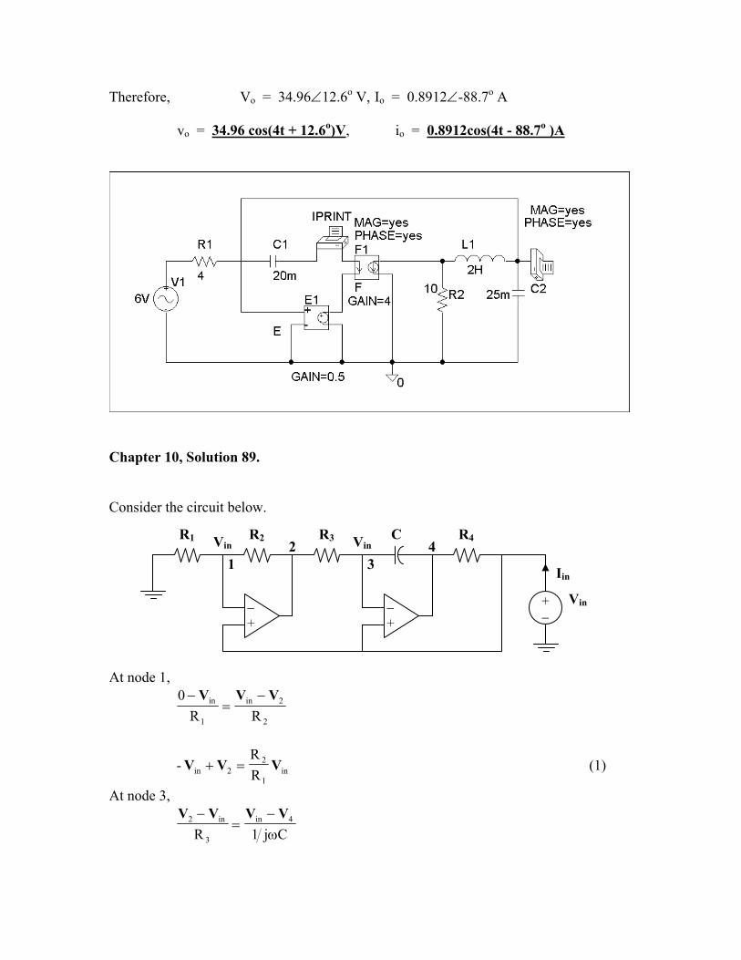
Therefore, Vo = 34.96∠12.6o V, Io = 0.8912∠-88.7o A
vo = 34.96 cos(4t + 12.6o)V, io = 0.8912cos(4t - 88.7o )A
onsider the circuit below.
Chapter 10, Solution 89. C
At node 1,
in
−
2
2
1
in
RVVV
=−0
in
R−
in1
22in R
R- VVV =+ (1)
At node 3,
Cj1R4in
3
in2
ω−
=− VVVV
V
C R1 R2 Vin
+
Iin
in
3
R3 R4
− +
−+
V1
2 4
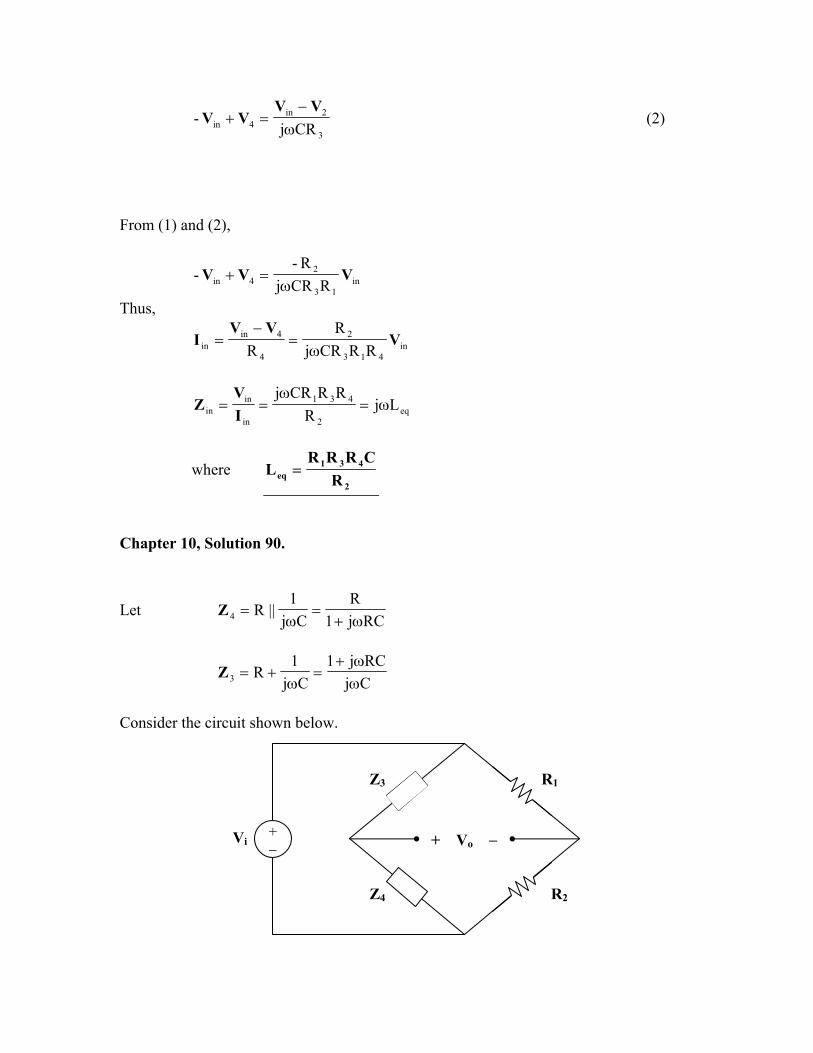
3
2in4in CRj
-ω−
=+VV
VV (2)
rom (1) and (2),
F
in13
24in RCRj
R-- VVV
ω=+
1R
Thus,
in43
2
4
4inin RCRj
RR
VVV
Iω
=−
=
eq2
431
in
inin Lj
RRRCRj
ω=ω
==IV
Z
where 2
431eq R
CRRRL =
Chapter 10, Solution 90.
et
LRCj1
RC
1||R
ω+==Z
C
j4 ω
CjRCj1
Cj1
R3 ωω+
=ω
+=Z
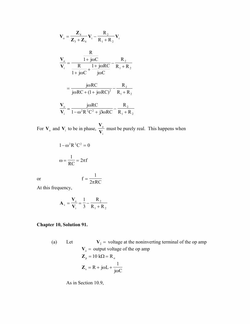
onsider the circuit shown below.
R2Z4
+ Vo −Vi + −
Z3 R1
i21
2i
43
4o RR
RVV
ZZZ
V+
−+
=
21
2
i
o
RRR
CjRCj1
Cj1R
Cj1R
+−
ωω+
+ω+
ω+=
VV
21
22 RR
R)RCj1(RCj
RCj+
−ω++ω
ω=
21
2222
i
o
RRR
RC3jCR1RCj
+−
ω+ω−ω
=V
V
For and to be in phase, oV iVi
o
VV
must be purely real. This happens when
0CR1 222 =ω−
f2RC1
π==ω
or RC21
fπ
=
At this freque cy, n
21
2
i
ov RR
R31
+−==
VV
A
Chapter 10, Solution 91.
(a) Let
=2V voltage at the noninverting terminal of the op amp output=oV voltage of the op amp
Rk10 =Ω op =Z1Cj
LjRs ω+ω+=Z
s in Section 10.9, A
Cj
LjRR
R
o
o
ps
p
o
2
ω−ω++
=+
=ZZ
ZVV
)1LC(j)RR(CCR
2o
o
o
2
−ω++ωω
=VV
For this to be purely real,
LC1
01LC o2o =ω→=−ω
)102)(104.0(21
LC21
f9-3-o
××π=
π=
=of 180 kHz
(b) At oscillation,
o
o
oo
oo
o
2
RRR
)RR(CCR
+=
+ωω
=VV
This must be compensated for by
52080
12
ov =+==
VV
A
==→=+ o
o
o R4R51
RRR
40 kΩ
Chapter 10, Solution 92.
Let voltage at the noninverting terminal of the op amp =2V=oV output voltage of the op amp
os R=Z
)1LC(jRLRL
Lj1
CjR1
1R||
Cj1
||Lj 2p −ω+ωω
=
ω+ω+
=ω
ω=Z
As in Section 10.9,
)1LC(jRLRL
R
)1LC(jRLRL
2o
2
ps
p
o
2
−ω+ωω
+
−ω+ωω
=+
=ZZ
ZVV
)1LC(RjRLRRLRL
2ooo
2
−ω+ω+ωω
=VV
For this to be purely real,
LC21
f1LC o2o π
=→=ω
(a) At , oω=ω
oooo
o
o
2
RRR
LRRLRL
+=
ω+ωω
=VV
This must be compensated for by
11k100k1000
1RR
1o
f
2
ov =+=+==
VV
A
Hence,
==→=+
R10R111
RRR
oo
100 kΩ
(b) )102)(1010(2
1f
9-6-o××π
=
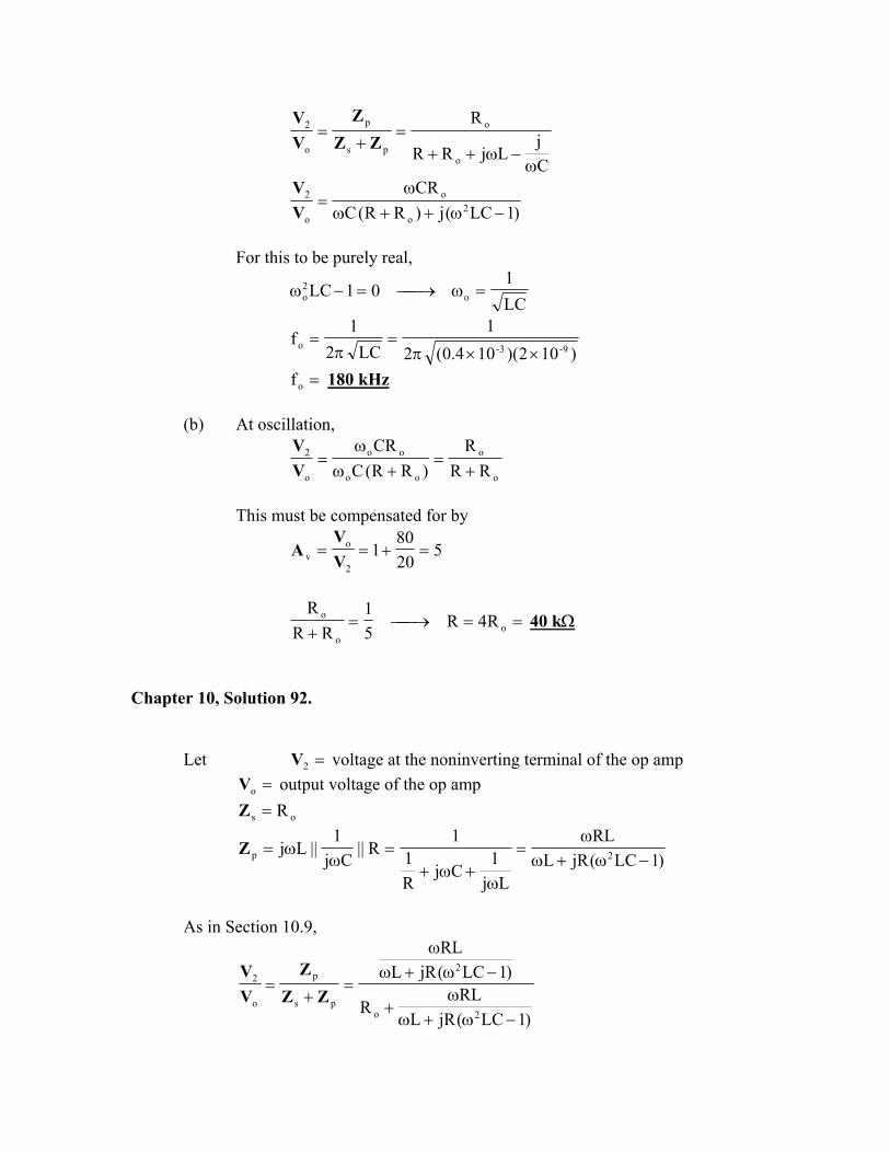
=of 1.125 MHz Chapter 10, Solution 93. As shown below, the impedance of the feedback is
jωL
1Cj1ω2Cj
1ω
ZT
ω+ω
ω=
21T Cj
1Lj||
Cj1
Z
)CLCCC(j
LC1
Cj-
LjCj-
Cj-
LjCj-
212
21
2
21
21T ω−+
ω−ω=
ω+ω+
ω
ω+ω
ω=Z
In order for to be real, the imaginary term must be zero; i.e. TZ
0CLCCC 212o21 =ω−+
T21
212o LC
1CLCCC
=+
=ω
To LC2
1f
π=
Chapter 10, Solution 94. If we select C
nF20C21 ==
nF102
CCC
CCC 1
21
21T ==
+=
Since T
o LC21
fπ
= ,
mH13.10)1010)(102500)(4(
1C)f2(
1L 9-62
T2 =
××π=
π=
=××π
=ω
=)1020)(1050)(2(
1C1
X 9-32
c 159 Ω
We may select and , say Ω= k20R i if RR ≥ Ω= k20R f . Thus,
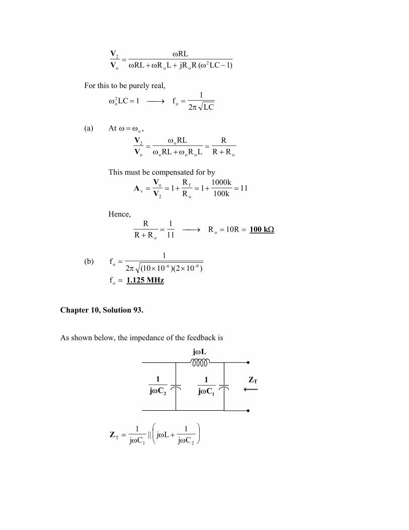
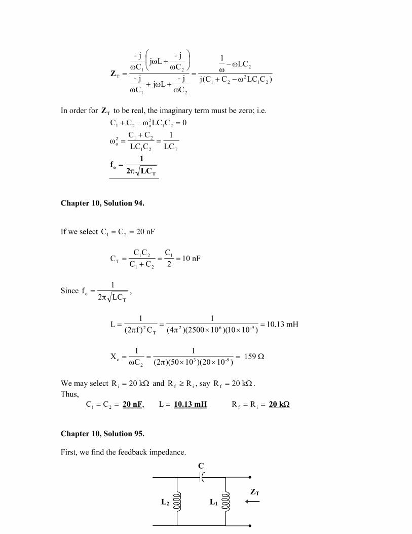
== 21 CC 20 nF, =L 10.13 mH == if RR 20 kΩ Chapter 10, Solution 95. First, we find the feedback impedance.
C
L1L2
ZT
ω
+ωω=Cj
1Lj||Lj 21TZ
)1)LL(C(j)L1(CL
Cj
LjLj
Cj
LjLj
212
212
21
21
T −+ωω−ω
=
ω−ω+ω
ω−ωω
=Z
In order for to be real, the imaginary term must be zero; i.e. TZ
01)LL(C 212o =−+ω
)LL(C1
f221
oo +=π=ω
)LL(C21
f21
o +π=
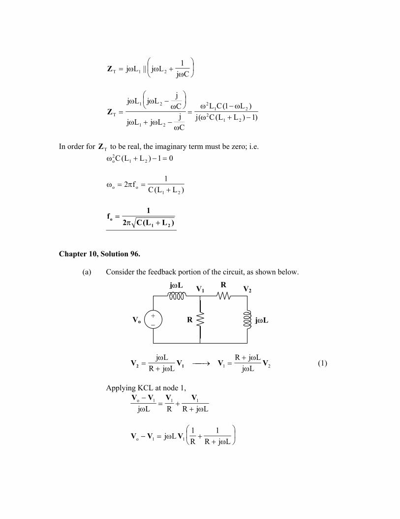
Chapter 10, Solution 96.
(a) Consider the feedback portion of the circuit, as shown below.
V2V1
+ −
R
R
jωL
Vo jωL
21 LjLjR
LjRLj
VVVV 12 ωω+
=→ω+
ω= (1)
Applying KCL at node 1,
LjRRLj111o
ω++=
ω− VVVV
ω+
+ω=−LjR
1R1
Lj 11o VVV
ω+ω−ω
+=)LjR(RLRL2j
122
1o VV
(2) From (1) and (2),
2
22
o )LjR(RLRL2j
1Lj
LjRVV
ω+ω−ω
+
ωω+
=
RLjLRL2jRLjR 222
2
o
ωω−ω+ω+
=VV
RLjLR
3
1222
o
2
ωω−
+=
VV
=o
2
VV
)LRRL(j31
ω−ω+
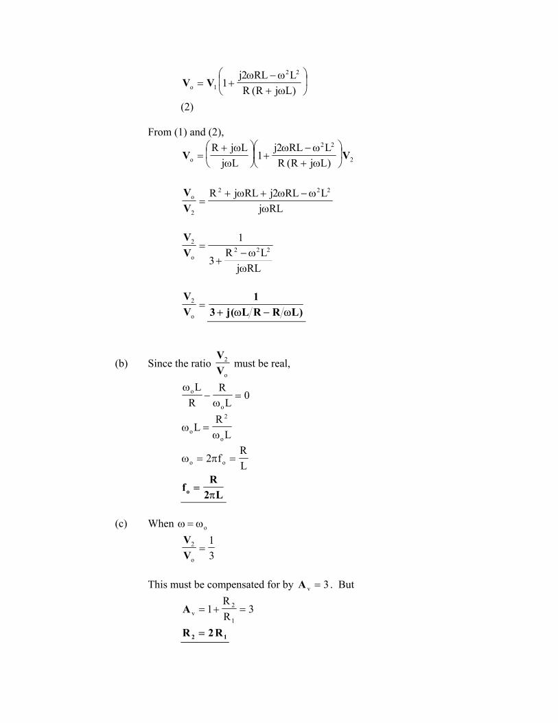
(b) Since the ratio o
2
VV
must be real,
0L
RR
L
o
o =ω
−ω
LR
Lo
2
o ω=ω
LR
f2 oo =π=ω
L2R
fo π=
(c) When oω=ω
31
o
2 =VV
This must be compensated for by 3v =A . But
3RR
11
2v =+=A
12 R2R =