chapter 10 arc welding and cutting process section i. general
TRANSCRIPT
TC 9-237
CHAPTER 10
ARC WELDING AND CUTTING PROCESS
Section I. GENERAL
10-1. DEFINITION OF ARC WELDING
a. Definition. In the arc welding process, the weld is produced by the extremeheat of an electric arc drawn between an electrode and the workpiece, or in somecases, between two electrodes. Welds are made with or without the application ofpressure and with or without filler metals. Arc welding processes may be dividedinto two classes based on the type of electrode used: metal electrodes and carbonelectrodes. Detailed descriptions of the various processes may be found in chapter6, paragraph 6-2.
(1) Metal electrodes. Arc welding processes that fall into this categoryinclude bare metal-arc welding, stud welding, gas shielded stud welding, submergedarc welding, gas tungsten arc welding, gas metal-arc welding, shielded metal-arcwelding, atomic hydrogen welding, arc spot welding, and arc seam welding.
(2) Carbon electrodes. Arc welding processes thatinclude carbon-arc welding, twin carbon-arc welding, gasshielded carbon-arc welding.
b. Weld Metal Deposition.
fall into this categorycarbon-arc welding, and
(1) General. In metal-arc welding, a number of separate forces are responsi-ble for the transfer of molten filler metal and molten slag to the base metal.These forces are described in (2) through (7) helm.
(2) Vaporization and condensation. A small part of the metal passing throughthe arc, especially the metal in the intense heat at the end of the electrode, isvaporized. some of this vaporized metal escapes as spatter, but most of it iscondensed in the weld crater, which is at a much lower temperature. This occurswith all types of electrodes and in all welding positions.
(3) Gravity. Gravity affects the transfer of metal in flat position weld-ing . In other positions, small electrodes must be used to avoid excessive loss ofweld metal, as the surface tension is unable to retain a large amount of moltenmetal in the weld crater.
(4) Pinch effect. The high current passing through the molten metal at thetip of the electrode sets up a radial compressive magnetic force that tends topinch the molten globule and detach it from the electrode.
(5) Surface tension. This force holds filler metal and the slag globules incontact with the molten base or weld metal in the crater. It has little to do withthe transfer of metal across the arc,molten weld metal in place and in the
but is an important factorshaping of weld contours.
in retaining the
10-1

TC 9-237
10-1. DEFINITION OF ARC WELDING (cont)
(6) Gas stream from electrode coatings. Gases are produced by the burningand volatilization of the electrode covering and are expanded by the heat of theboiling electrode tip. The velocity and movement of this gas stream give the smallparticles in the arc a movement away from the electrode tip and into the moltencrater on the work.
(7) Carbon monoxide evolution from electrode. According to this theory ofmetal movement in the welding arc, carbon monoxide is evolved within the moltenmetal at the electrode tip, causing miniature explosions which expel molten metalaway from the electrode and toward the work. This theory is substantiated by thefact that bare wire electrodes made of high purity iron or “killed steel” (i.e.,steel that has been almost completely deoxidized in casting) cannot he used success-fully in the overhead position. The metal transfer from electrode to the work, thespatter, and the crater formation are, in this theory, caused by the decarburizingaction in molten steel.
c . Arc Crater. Arc craters are formal by the pressure of expanding gases fromthe electrode tip (arc blast), forcing the liquid metal towards the edges of thecrater . The higher temperature of the center , as compared with that of the sidesof the crater, causes the edges to cool first. Metal is thus drawn from the centerto the edges, forming a low spot.
10-2. WELDING WITH CONSTANT CURRENT
The power source is the heart of all arc welding process. Two basic types of powersources are expressed by their voltage-ampere output characteristics. The constantcurrent machine is considered in this paragraph. The other power source, the con-stant voltage machine, is discussed in paragraph 10-3. The static output character-istic curve produced by both sources is shown in figure 10-1. The characteristiccurve of a welding machine is obtained by measuring and plotting the output voltageand the output current while statically loading the machine.
a. The conventional machine is known as the constant current (CC) machine, orthe variable voltage type. The CC machine has the characteristic drooping volt-am-pere curve, (fig. 10-1), and has been used for many years for the shielded metalarc welding process. A constant-current arc-welding machine is one which has meansfor adjusting the arc current. It also has a static volt-ampere curve that tendsto produce a relatively constant output current. The arc voltage, at a given weld-ing current, is responsive to the rate at which a consumable electrode is fed intothe arc. When a nonconsumable electrode is used, the arc voltage is responsive tothe electrode-to-work distance. A constant-current arc-welding machine is usuallyused with welding processes which use manually held eletrodes, continuously fedconsumable electrodes, or nonconsumable electrodes. If the arc length varies be-cause of external influences, and slight changes in the arc voltage result, thewelding current remains constant.
b. The conventional or constant current (CC) type power source may have directcurrent or alternating current output. It is used for the shielded metal-arc weld-ing process, carbon arc welding and gouging, gas tungsten arc welding, and plasmaarc welding. It is used for stud welding and can be used for the continuous wireprocesses when relatively large electrode wires are used.
10-2

TC 9-237
c. There are two control systems for constant current welding machines: thesingle-control machine and the dual-control machine.
(1) The single-control machine has one adjustment which changes the currentoutput from minimum to maximum, which is usually greater than the rated output ofthe machine. The characteristic volt-ampere curve is shown by figure 10-2. Theshaded area is the normal arc voltage range. By adjusting the current control, alarge number of output curves can be obtained. The dotted lines show intermediateadjustments of the machine. With tap or plug-in machines, the number of coverswill correspond to the number of taps or plug-in combinations available. Mosttransformer and transformer-rectifier machines are single-control welding machines.
Figure 10-2. Curve for single control welding machine.
10-3

TC 9-237
10-2. WELDING WITH CONSTANT CURRENT (cont)
(2) Dual control machines have both current and voltage controls. They havetwo adjustments , one for coarse-current control and the other for fine-currentcontrol, which also acts as an open-circuit voltage adjustment. Generator weldingmachines usually have dual controls. They offer the welder the most flexibilityfor different welding requirements. These machines inherently have slope control.The slope of the characteristic curve can be changed from a shallow to a steepslope according to welding requirements. Figure 10-3 shows some of the differentcurves that can be obtained. Other tunes are obtained with intermediate open-cir-cuit voltage settings. The slope is changed by changing the open-circuit voltagewith the fine—current control adjustment bob. The coarse adjustment sets thecurrent output of the machine in steps from the minimum to the maximum current.The fine—current control will change the open-circuit voltage from approximately 55volts to 85 volts. However, when welding, this adjustment does not change arcvoltage. Arc voltage is controlled by the welder by changing the length of thewelding arc. The open-circuit voltage affects the ability to stike an arc. Ifthe open-circuit voltage is much below 60 volts, it is difficult to strike an arc.
10-4

TC 9-237
(a) The different slopes possible with a dual-control machine have an impor-tant effect on the welding characteristic of the arc. The arc length can vary,depending on the welding technique. A short arc has lower voltage and the long archas higher voltage. With a short arc (lower voltage), the power source producesmore current, and with a longer arc (higher voltage), the power source providesless welding current. This is illustrated by figure 10-4, which shows three curvesof arcs and two characteristic curves of a dual-control welding machine. The threearc curves are for a long arc, a normal arc, and the lower curve is for a shortarc. The intersection of a curve of an arc and a characteristic curve of a weldingmachine is known as an operating point. The operating point changes continuouslyduring welding. While welding, and without changing the control on the machine,the welder can lengthen or shorten the arc and change the arc voltage from 35 to 25volts. With the same machine setting, the short arc (lower voltage) is a high-cur-rent arc. Conversely, the long arc (high voltage) is a lower current arc. Thisallows the welder to control the size of the molten puddle while welding. When thewelder purposely and briefly lengthens the arc, the current is reduced, the arcspreads out, and the puddle freezes quicker. The amount of molten metal is re-duced, which provides the control needed for out-of-position work. This type ofcontrol is built into conventional constant current type of machine, single- ordual-control, ac or dc.
(b) With the dual-control machine,more or less change of current for a givenfigure 10-4 are obtained on a dud-control
the welder can adjust the machine forchange of arc voltage. Both curves inmachine by adjusting the fine control
knob. The top curve shows an 80-volt open-circuit voltage and the bottom curveshins a 60-volt open-circuit voltage. With either adjustment, the voltage andcurrent relationship will stay on the same curve or line. Consider first the 80-volt open-circuit curve which produces the steeper slope. When the arc is long
10-5

TC 9-237
10-2. WELDING WITH CONSTANT CURRENT (cont)
with 35 volts and is shortened to 25 volts, the current increases. This is donewithout touching the machine control. The welder manipulates the arc. With theflatter, 60-volt open-circuit curve, when the arc is shortened from 35 volts to 25volts, the welding current will increase almost twice as much as it did when follow-ing the 80-volt open-circuit curve. The flatter slope curve provides a digging arcwhere an equal change in arc voltage produces a greater change in arc current. Thesteeper slope curve has less current change for the same change in arc length andprovides a softer arc. There are many characteristic curves between the 80 and 60open circuit voltage curves, and each allows a different current change for thesame arc voltage change. This is the advantage of a dual-control welding machineover a single-control type, since the slope of the curve through the arc voltagerange is adjustable only on a dual-control machine. The dual-control generatorwelding machine is the most flexible of all types of welding power sources, sinceit allows the welder to change to a higher-current arc for deep penetration or to alower-current, less penetrating arc by changing the arc length. This ability tocontrol the current in the arc over a fairly wide range is extremely useful formaking pipe welds.
d. The rectifier welding machine, technically known as the transformer-rectifi-er, produces direct current for welding. These machines are essentially single-con-trol machines and have a static volt ampere output characteristic curve similar tothat shown by figure 10-4, p 10-5. These machines, though not as flexible as thedual-control motor generator, can be used for all types of shielded metal arc weld-ing where direct current is required. The slope of the volt-ampere curve throughthe welding range is generally midway between the maximum and minimum of a dual-con-trol machine.
e. Alternating current for welding is usually produced by a transformer typewelding machine, although engine-driven alternating current generator welding ma-chines are available for portable use. The static volt ampere characteristic curveof an alternating current power source the same as that shown by figure 10-4, p10-5. some transformer welding power sources have fine and coarse adjustmentknobs, but these are not dual control machines unless the open-circuit voltage ischanged appreciably. The difference between alternating and direct current weldingis that the voltage and current pass through zero 100 or 120 times per second,according to line frequency or at each current reversal. Reactance designed intothe machine causes a phase shift between the voltage and current so that they bothdo not go through zero at the same instant. When the current goes through zero,the arc is ex t inguished, but because of the phase difference, there is voltagepresent which helps to re-establish the arc quickly. The degree of ionization inthe arc stream affects the voltage required to re-establish the arc and the overallstability of the arc. Arc stabilizers (ionizers) are included in the coatings ofelectrodes designed for ac welding to provide a stable arc.
f . The constant—current type welding machine can be used for some automaticwelding processes. The wire feeder and control must duplicate the motions of thewelder to start and maintain an arc. This requires a complex system with feedbackfrom the arc voltage to compensate for changes in the arc length. The constant-cur-rent power supplies are rarely used for very small electrode wire welding processes.
g. Arc welding machines have been developed with true constant—current volt-am-pere static characteristics, within the arc voltage range, as shown by figure10-5. A welder using this type of machine has little or no control over welding
10-6

TC 9-237
current by shortening or lengthening the arc, since the welding current remains thesame whether the arc is short or long. This is a great advantage for gas tungstencurrent by shortening or lengthening the arc, since the welding current remains thesame whether the arc is short or long. This is a great advantage for gas tungstenarc welding, since the working arc length of the tungsten arc is limited. Inshield metal-arc welding, to obtain weld puddle control, it is necessary to beable to change the current level while welding. This is done by the machine, whichcan be programmed to change from a high current (HC) to a low current (LC) on arepetitive basis, known as pulsed welding. In pulsed current welding there are twocurrent levels, the high current and low current, sometimes called background cur-By programming a control circuit, the output of the machine continuouslyswitches from the high to the low current as shown by figure 10-6, p 10-8. Thelevel of both high and low current is adjustable. In addition, the length of timefor the high and low current pulses is adjustable. This gives the welder the neces-sary control over the arc and weld puddle. Pulsed current welding is useful forshielded metal-arc welding of pipe when using certain types of electrodes. Pulsedarc is very useful when welding with the gas tungsten arc welding process.
10-7

TC 9-237
10-2. WELDING WITH CONSTANT CURRENT (cont)
10-3. WELDING WITH CONSTANT VOLTAGE
The second type of power source is the constant voltage (CV) machine or the con-stant potential (CP) machine. It has a relatively flat volt-ampere characteristiccurve.
The static output characteristic tune produced by both the CV and CC ma-chine is shown by figure 10-1, p 10-3. The characteristic curve of a welding ma-chine is obtained by measuring and plotting the output voltage and the output cur-rent while statically loading the machine. The constant voltage (CV) characteris-tic curve is essentially flat but with a slight droop. The curve may be adjustedup and down to change the voltage; however, it will never rise to as high an open-circuit voltage as a constant current (CC) machine. This is one reason that theconstant voltage (CV) machine is not used for manual shielded metal arc weldingwith covered electrodes. It is only used for continuous electrode wire welding.The circuit consists of a pure resistance load which is varied from the minimum orno load to the maximum or short circuit. The constant current (CC) curve showsthat the machine produces maximum output voltage with no load, and as the loadincreases, the output voltage decreases. The no-load or open-circuit voltage isusually about 80 volts.
b. The CV electrical system is the basis of operation of the entire commercialelectric power system. The electric power delivered to homes and available atevery receptacle has a constant voltage. The same voltage is maintained continuous-ly at each outlet whether a small light bulb, with a very low wattage rating, or aheavy-duty electric heater with a high wattage rating, is connected. The currentthat flows through each of these circuits will be different based on the resistanceof the particular item or appliance in accordance with Ohm’s law. For example, thesmall light bulb will draw less than 0.01 amperes of current while the electricheater may draw over 10 amperes. The voltage throughout the system remains con–stant, but the current flowing through each appliance depends on its resistance orelectrical load. The same principle is utilized by the CV welding system.
10-8

TC 9-237
c. When a higher current is used when welding, the electrode is melted off morerapidly. With loW current, the electrode melts off slower. This relationship be-tween melt-off rate and welding current applies to all of the arc welding processesthat use a continuously fed electrode. This is a physical relationship that de-pends upon the size of the electrode, the metal composition, the atmosphere thatsurrounds the arc, and welding current. Figure 10-7 shows the melt-off rate curvesfor different sizes of steel electrode wires in a C02 atmosphere. Note that thesecurves are nearly linear, at least in the upper portion of the curve. Similarcurves are available for all sizes of electrode wires of different compositions andin different shielding atmospheres. This relationship is definite and fixed, butsome variations can occur. This relationship is the basis of the simplified con-trol for wire feeding using constant voltage. Instead of regulating the electrodewire feed rate to maintain the constant arc length, as is done when using a con-stant current power source, the electrode wire is fed into the arc at a fixedspeed. The power source is designed to provide the necessary current to melt offthe electrode wire at this same rate. This concept prompted the development of theconstant voltage welding power source.
d. The volt-ampere characteristics of the constant voltage power source shownby figure 10-8, p 10-10, was designed to produce substantially the same voltage atno load and at rated or full load. It has characteristics similar to a standardcommercial electric power generator. If the load in the circuit changes, the powersource automaticaly adjusts its current output to satisfy this requirement, andmaintains essentially the same voltage across the output terminals. This ensures aself-regulating voltage power source.
10-9

TC 9-237
10-3. WELDING WITH CONSTANT VOLTAGE (cont)
e . Resistances or voltage drops occur in the welding arc and in the weldingcables and connecters, in the welding gun, and in the electrode length beyond thecurrent pickup tip. These voltage drops add up to the output voltage of the weld-ing machine, and represent the electrical resistance load on the welding powersource. When the resistance of any component in the external circuit changes, thevoltage balance will be achieved by changing the welding current in the system.The greatest voltage drop occurs across the welding arc. The other voltage dropsin the welding cables and connections are relatively small and constant. The volt-age drop across the welding arc is directly dependent upon the arc length. A smallchange in arc volts results in a relatively large change in welding current. Fig-ure 10-9 shins that if the arc length shortens slightly, the welding current in-creases by approximately 100 amperes. This change in arc length greatly increasesthe melt-off rate and quickly brings the arc length back to normal.
10-10

TC 9-237
f . The constant voltage power source is continually changing its current outputin order to maintain the voltage drop in the external portion of the welding cir-cuit . Changes in wire feed speed which might occur when the welder moves the guntoward or away from the work are compensated for by changing the current and themelt-off rate briefly until equilibrium is re-established. The same correctiveaction occurs if the wire feeder has a temporary reduction in speed. The CV powersource and fixed wire feed speed system is self-regulating. Movemment of the cableassembly often changes the drag or feed rate of the electrode wire. The CV weldingpower source provides the proper current so that the malt-off is equal to the wirefeed rate. The arc length is controlled by setting the voltage on the powersource. The welding current is controlled by adjusting the wire feed speed.
g. The characteristics of the welding power source must be designed to providea stable arc when gas metal arc welding with different electrode sizes and metalsand in different atmospheres. Most constant voltage power sources have taps or ameans of adjusting the slope of the volt-ampere curve. A curve having a slope of1-1/2 to 2 volts per hundred amperes is best for gas metal arc welding withnonferrous electrodes in inert gas, for submerged arc welding, and for flux-coredarc welding with larger-diameter electrode wires. A curve having a medium slope of2 to 3 volts per hundred amperes is preferred for CO2 gas shielded metal arc weld-ing and for small flux-cored electrode wires. A steeper slope of 3 to 4 volts perhundred amperes is reccomended for short circuiting arc transfer. These threeslopes are shown in figure 10-10. The flatter the curve, the more the currentchanges for an equal change in arc voltage.
h. The dynamic characteristics of the power source must be carefully engi-neered. Refer again to figure 10-9. If the voltage changes abruptly with a shortcircuit, the current will tend to increase quickly to a very high value. This isan advantage in starting the arc but will create unwanted spatter if not con-trolled. It is controlled by adding reactance or inductance in the circuit. Thischanges the time factor or response time and provides for a stable arc. In mostmachines, a different amount of inductance is included in the circuit for the dif-ferent slopes.
10-11

TC 9-237
10-3. WELDING WITH CONSTANT VOLTAGE (cont)
i. The constant voltage welding power system has its greatest advantage whenthe current density of the electrode wire is high. The current density (amperes/sqin.) relationship for different electrode wire sizes and different currents isshown by figure 10-11. There is a vast difference between the current densityemployed for gas metal arc welding with a fine electrode wire compared with conven-tional shielded metal arc welding with a covered electrode.
j . Direct current electrode positive (DCEP) is used for gas metal arc welding.When dc electrode negative (DCEN) is used, the arc is erratic and produces an infe-rior weld. Direct current electrode negative (DCEN) can be used for submerged arcwelding and flux-cored arc welding.
k. Constant voltage welding with alternating current is normally not used. Itcan be used for submerged arc welding and for electroslag welding.
l . The constant voltage power system should not be used for shielded metal-arcwelding. It may overload and damage the power source by drawing too much currenttooand
long. It can be used for carbon arc cutting and gouging with small electrodesthe arc welding processes.
10-12

TC 9-237
10-4. DC STRAIGHT AND REVERSE POLARITY WELDING
a. General. The electrical arc welding circuit is the same as any electricalcircuit . In the simplest electrical circuits, there are three factors: current,or the flow of electricity; pressure, or the force required to cause the current toflow; and resistance, or the force required to regulate the flow of current.
(1) Current is a rate of flew and is measured by the amount of electricitythat flows through a wire in one second. The term ampere denotes the amount ofcurrent per second that flows in a circuit. The letter I is used to designatecurrent amperes.
(2) Pressure is the force that causes a current to flow. The measure ofelectrical pressure is the volt. The voltage between two points in an electricalcircuit is called the difference in potential. This force or potential is calledelectromotive force or EMF. The difference of potential or voltage causes currentto flow in an electrical circuit. The letter E is used to designate voltage or EMF.
(3) Resistance is the restriction to current flow in an electrical circuit.Every component in the circuit, including the conductor, has some resistance tocurrent flow. Current flows easier through some conductors than others; that is,the resistance of some conductors is less than others. Resistance depends on thematerial, the cross-sectional area, and the temperature of the conductor. The unitof electrical resistance is the ohm. It is designated by the letter R.
b. Electrical circuits. A simple electrical circuit is shown by figure 10-12.This circuit includes two meters for electrical measurement: a voltmeter, and anammeter. It also shows a symbol for a battery. The longer line of the symbolrepresents the positive terminal. Outside of a device that sets up the EMF, suchas a generator or a battery, the current flows from the negative (-) to the posi-tive (+). The arrow shows the direction of current flow. The ammeter is a lowresistance meter shown by the round circle and arrow adjacent to the letter I. Thepressure or voltage across the battery can be measured by a voltmeter. Thevoltmeter is a high resistance meter shown by the round circle and arrow adjacentto the letter E. The resistance in the circuit is shown by a zigzag symbol. Theresistance of a resistor can be measured by an ohmmeter. An ohmmeter must never beused to measure resistance in a circuit when current is flowing.. .
10-13

TC 9-237
10-4. DC STRAIGHT AND REVERSE POLARITY WELDING (cont)
c . Arc Welding Circuit. A few changes to the circuit shown by figure 10-12, p10-13, can be made to represent an arc welding circuit. Replace the battery with awelding generator, since they are both a source of EMF (or voltage), and replacethe resistor with a welding arc which is also a resistance to current flow. Thearc welding circuit is shown by figure 10-13. The current will flow from the nega-t ive terminal through the resistance of the arc to the positive terminal.
d. Reverse and Straight Polarity. In the early days of arc welding, when weld-ing was done with bare metal electrodes on steel, it was normal to connect thepositive side of the generator to the work and the negative side to the electrode.This provided 65 to 75 percent of the heat to the work side of the circuit to in-crease penetration. When welding with the electrode negative, the polarity of thewelding current was termed straight. When conditions such as welding cast iron ornonferrous metals made it advisable to minimize the heat in the base metal, thework was made negative and the electrode positive , and the welding current polaritywas said to be reverse. In order to change the polarity of the welding current, itwas necessary to remove the cables from the machine terminals and replace them inthe reverse position. The early coated electrodes for welding steel gave bestresults with the electrode positive or reverse polarity; however, bare electrodeswere still used. It was necessary to change polarity frequently when using bothbare and covered electrodes. Welding machines were equipped with switches that
The weldercould quickly change the polarity of the welding current. In marking welding ma-chines and polarity switches, these old terms were used and indicated the polarityas straight when the electrode was negative, and reverse when the electrode waspositive. Thus, electrode negative (DCEN) is the same as straight polarity (dcsp),and electrode positive (DCEP) is the same as reverse polarity (dcrp).
changed the polarity of the terminals and with dual reading meters.
e. The ammeter used in a welding circuit is a millivoltmeter calibrated inamperes connected across a high current shunt in the welding circuit. The shunt isa calibrated, very low resistance conductor. The voltmeter shown in figure 10-12will measure the welding machine output and the voltage across the arc, which areessentially the same. Before the arc is struck or if the arc is broken, thevoltmeter will read the voltage across the machine with no current flowing in thec i rcu i t . This is known as the open circuit voltage, and is higher than the arcvoltage or voltage across the machine when current is flowing.
f. Another unit in an electrical circuit is the unit of power. The rate ofproducing or using energy is called power, and is measured in watts. Power incircuit is the product of the current in amperes multiplied by the pressure involts . Power is measured by a wattmeter, which is a combination of an ammmetera voltmeter.
10-14
a
and

TC 9-237
g. In addition to power, it is necessary to know the amount of work involved.Electrical work or energy is the product of power multiplied by time, and is ex-pressed as watt seconds, joules, or kilowatt hours.
10-5. WELDING ARCS
a. General. The arc is used as a concentrated source of high temperature heatthat can be moved and manipulated to melt the base metal and filler metalduce welds.
b. Types of Welding Arcs. There are two basic types of welding arcs.the nonconsumable electrode and the other uses the consumable electrode.
(1) The nonconsumable electrode does not melt in the arC and filler
to pro-
One uses
metal is not carried across the arc stream. The welding processes that use the noncon-sumable electrode arc are carbon arc welding, gas tungsten arc welding, and plasmaarc welding.
(2) The consumable electrode melts in the arc and is carried across the arcin a stream to become the deposited filler metal. The welding processes that usethe consumable electrode arC are shielded metal arc welding, gas metal arc welding,flux-cored arc welding, and submerged arc welding.
c. Function of the Welding Arc.
(1) The main function of the arc is to procduce heat. At the same time, itproduces a bright light, noise, and, in a special case, bombardment that removessurface films from the base metal.
(2) A welding arc is a sustained electrical discharge through a high conduct-ing plasma. It produces sufficient thermal energy which is useful for joiningmetals by fusion. The welding arc is a steady-state condition maintained at thegap between an electrode and workpiece that can carry current ranging from as loWas 5 amperes to as high as 2000 amperes and a voltage as low as 10 volts to thehighest voltages used on large plasma units. The welding arc is somewhat differentfrom other electrical arcs since it has a point-to-plane geometric configuration,the point being the arcing end of the electrode and the plane being the arcing areaof the workpiece. Whether the electrode is positive or negative, the arc is re-stricted at the electrode and spreads out toward the workpiece.
(3) The length of the arc is proportional to the voltage across the arC . Ifthe arc length is increased beyond a certain point, the arc will suddenly go out.This means that there is a certain current necessary to sustain an arc of differentlengths. If a higher current is uSe d , a longer arc can be maintained.
(4) The arc column is normally round in cross section and is made up of aninner core of plasma and an outer flame. The plasma carries most of the current.The plasma of a high—current arc can reach a temperature of 5000 to 50,0000 Kelvin. The outer flame of the arc is much cooler and tends to keep the plasmain the center. The temperature and the diameter of the central plasma depend onthe amount of current passing through the arc, the shielding atmosphere, and theelectrode size and type.
10-15

TC 9-237
10-5. WELDING ARCS
(5) The curve
(cont )
of an arc, shown by figure 10-14, takes on a nonlinear formwhich in one area has a negative slope. The arc voltage increases slightly as thecurrent increases. This is true except for the very low—current arc which has ahigher arc voltage. This is because the low—current plasma has a fairly smallcross-sectional area, and as the current increases the cross section of the plasmaincreases and the resistance is reduced. The conductivity of the arc increases ata greater rate than simple proportionality to current.
(6) The arc is maintained when electrons are emitted or evaporated from thesurface of the negative pole (cathode) and flow across a region of hot electricallycharged gas to the positive pole (anode), where they are absorbed Cathode and.anode are electrical terms for the negative and positive poles.
(7) Arc action can best be explained by considering the dc tungsten electrodearc in an inert gas atmosphere as shown by figure 10-15. On the left, the tungstenarc is connected for direct current electrode negative (DCEN). When the arc isstarted, the electrode becomes hot and emits electrons. The emitted electrons areattracted to the positive pole, travel through the arc gap, and raise the tempera-ture of the argon shielding gas atoms by colliding with them. The collisions ofelectrons with atoms and molecules produce thermal ionization of some of the atomsof the shielding gas. The positively charged gaseous atoms are attracted to thenegative electrode where their kinetic (motion) energy is converted to heat. Thisheat keeps the tungsten electrode hot enough for electron emission. Emission ofelectrons from the surface of the tungsten cathode is known as thermionic emis-s ion. Positive ions also cross the arc. They travel from the positive pole, orthe work, to the negative pole, or the electrode. Positive ions are much heavierthan the electrons, but help carry the current flow of the relatively low voltagewelding arc. The largest portion of the current flow, approximately 99 percent, isvia electron flew rather than through the flow of positive ions. The continuousfeeding of electrons into the welding circuit from the power source accounts forthe continuing balance between electrons and ions in the arc. The electrons collid-ing with the work create the intense localized heat which provides melting and deeppenetration of the base metals.
10-16

TC 9-237
(8) In the dc tungsten to base metal arc in an inert gas atmosphere, themaximum heat occurs at the positive pole (anode). When the electrode is positive(anode ) and the work is negative (cathode), as shown by figure 10-15, the electronsflow from the work to the electrode where they create intense heat. The electrodetends to overheat. A larger electrode with more heat-absorbing capacity is usedfor DCEP (dcsp) than for DCEN (dcrp) for the same welding current. In addition,since less heat is generated at the work, the penetration is not so great. Oneresult of DCEP welding is the cleaning effect on the base metal adjacent to the arcarea. This appears as an etched surface and is known as catholic etching. Itresults from positive ion bombardment. This positive ion bombardment also occursduring the reverse polarity half-cycle when using alternating current for welding.
(9) Constriction occurs in a plasma arc torch by making the arc pass througha small hole in a water-cooled copper nozzle. It is a characteristic of the arcthat the more it is cooled the hotter it gets; however, it requires a higher volt-age. By flowing additional gas through the small hole, the arc is further con-stricted and a high velocity, high temperature gas jet or plasma emerges. Thisplasma is used for welding, cutting, and metal spraying.
10-17

TC 9-237
10-5. WELDING
(10) The
ARCS (cont)
arc length or gap between the electrode and the work can be dividedinto three regions: a central region, a region adjacent to the electrode, and aregion adjacent to the work. At the end regions, the cooling effect of the elec-trode and the work causes a rapid drop in potential. These two regions are knownas the anode and cathode drop, according to the direction of current flow. Thelength of the central region or arc column represents 99 percent of the arc lengthand is linear with respect to arc voltage. Figure 10-16 shows the distribution ofheat in the arc, which varies in these three regions. In the central region, acircular magnetic field surrounds the arc. This field, produced by the currentflow, tends to constrict the plasma and is known as the magnetic pinch effect. Theconstriction causes high pressures in the arc plasma and extremely high veloci-t i es . This, in turn, produces a plasma jet. The speed of the plasma jet approach-es sonic speed.
(11 ) The cathode drop is the electrical connection between the arc column andthe negative pole (cathode). There is a relatively large temperature and potentialdrop at this point. The electrons are emitted by the cathode and given to the arccolumn at this point. The stability of an arc depends on the smoothness of theflow of electrons at this point. Tungsten and carbon provide thermic emissions,since both are good emitters of electrons. They have high melting temperatures,are practically nonconsumable, and are therefore used for welding electrodes.Since tungsten has the highest melting point of any metal, it is preferred.
(12) The anode drop occurs at the other end of the arc and is the electricalconnection between the positive pole (anode) and the arc column. The temperaturechanges from that of the arc column to that of the anode, which is considerablylower. The reduction in temperature occurs because there are fewer ions in thisregion. The heat liberated at the anode and at the cathode is greater than thatfrom the arc column.
d. Carbon Arc. In the carbon arc, a stable dc arc is obtained when the carbonis negative. In this condition, about 1/3 of the heat occurs at the negative pole(cathode), or the electrode, and about 2/3 of the heat occurs at the positive pole(anode), or the workpiece.
10-18

TC 9-237
e. Consumable Electrode Arc. In the consumable electrode welding arc, theelectrode is melted and molten metal is carried across the arc. A uniform arclength is maintained between the electrode and the base metal by feeding the elec-trode into the arc as fast as it melts. The arc atmosphere has a great effect onthe polarity of maximum heat. In shielded metal arc welding, the arc atmospheredepends on the composition of the coating on the electrode. Usually the maximumheat occurs at the negative ple (cathode). When straight polarity welding with anE6012 electrode, the electrode is the negative pole (DCEN) and the melt-off rate ishigh. Penetration is minimum. When reverse polarity welding with an E6010 elec-trode (DCEP), the maximum heat still occurs at the negative pole (cathode), butthis is now the base metal, which provides deep penetration. This is shown by fig-ure 10-17. With a bare steel electrode on steel, the polarity of maximum heat isthe positive pole (anode). Bare electrodes are operated on straight polarity(DCEN) so that maximum heat is at the basetion. When coated electrodes are operatedduced on each polarity of the arc.
metal (anode) to ensure enough penetra-on ac, the same amount of heat is pro-
f . Consumable Electrode Arc.
(1) The forces that cause metal to transfer across the arc are similar forall the consumable electrode arc welding processes. The type of metal transferdictates the usefulness of the welding process. It affects the welding position-that can be used, the depth of weld penetration, the stability of the welding pool,the surface contour of the weld, and the amount of spatter loss. The metal beingtransferred ranges from small droplets, smaller than the diameter of the electrode,to droplets larger in diameter than the electrode. The type of transfer depends onthe current density, the polarity of the electrode, the arc atmosphere, the elec-trode size, and the electrode composition.
(2) Several forces affect the transfer of liquid metal across an arc. Theseare surface tension, the plasma jet, gravity in flat position welding, and electro-magnetic force.
10-19

TC 9-237
10-5. WELDING ARCS (cont)(a) Surface tension of
tract to the smallest possiblea liquid causes thearea. This tension.
on the end of a melting electrode without regard to welding position. This force
surface of the liquid to con-tends to hold the liquid drops
works against the transfer of metal across the arc and helps keep molten metal inthe weld pool when welding in the overhead position.
(b) The welding arc is constricted at the electrode and spreads or flaresout at the workpiece. The current density and the arc temperature are the highestwhere the arc is most constricted, at the end of the electrode. An arc operatingin a gaseous atmosphere contains a plasma jet which flows along the center of thearc column between the electrode and the base metal. Molten metal drops in theprocess of detachment from the end of the electrode, or in flight, are acceleratedtowards the work piece by the plasma jet.
(c) Earth gravity detaches the liquid drop when the electrode is pointeddownward and is a restraining force when the electrode is pointing upward. Gravityhas a noticeable effect only at low currents. The difference between the mass ofthe molten metal droplet and the mass of the workpiece has a gravitational effectwhich tends to pull the droplet to the workpiece. An arc between two electrodeswill not deposit metal on either.
(d) Electromagnetic force also helps transfer metal across the arc. Whenthe welding current flows through the electrode, a magnetic field is set up aroundi t . The electromagnetic force acts on the liquid metal drop when it is about todetach from the electrode. As the metal melts, the cross-sectional area of theelectrode changes at the molten tip. The electromagnetic force depends upon wheth-er the cross section is increasing or decreasing. There are two ways in which theelectromagnetic force acts to detach a drop at the tip of the electrode. When adrop is larger in diameter than the electrode and the electrode is positive (DCEP),the magnetic force tends to detach the drop. When there is a constriction or neck-ing down which occurs when the drop is about to detach, the magnetic force actsaway from the point of constriction in both directions. The drop that has startedto separate will be given a push which increases the rate of separation. Figure10-18 illustrates these two points. Magnetic force also sets up a pressure withinthe liquid drop. The maximum pressure is radial to the axis of the electrode andat high currents causes the drop to lengthen. It gives the drop stiffness andcauses it to project in line with the electrode regardless of the welding position.
10-20

TC 9-237
10-6. AC WELDING
a. General. Alternating current is an electrical current which flows back andforth at regular intervals in a circuit. When the current rises from zero to amaximum, returns to zero, increases to a maximum in the opposite direction, andfinally returns to zero again, it is said to have completed one cycle.
(1) A cycle is divided into 360 degrees. Figure 10-19 is a graphical repre-sentation of a cycle and is called a sine wave. It is generated by one revolutionof a single loop coil armature in a two-pole alternating current generator. Themaximum value in one direction is reached at the 90° position, and in the otherdirection at the 270° pos i t ion .
(2) The number of times this cycle is repeated in one second is called thefrequency, measured in hertz.
b. Alternating current for arc welding normally has the same frequency as theline current. The voltage and current in the ac welding arc follow the sine waveand return to zero twice each cycle. The frequency is so fast that the arc appearscontinuous and steady. The sine wave is the simplest form of alternating current.
c. Alternating current and voltage are measured with ac meters. An acvoltmeter measures the value of both the positive and negative parts of the sinewave. It reads the effective, or root-mean-square (RMS) voltage. The effectivedirect current value of an alternating current or voltage is the product of 0.707multiplied by the maximum value.
d. An alternating current has no unit of its own, but is measured in terms ofdirect current, the ampere. The ampere is defined as a steady rate of flow, but analternating current is not a steady current. An alternating current is said to beequivalent to a direct current when it produces the same average heating effectunder exactly similar conditions. This is used since the heating effect of a nega-tive current is the same as that of a positive current. Therefore, an ac ammeterwill measure a value, called the effective value, of an alternating current whichis shown in amperes. All ac meters, unless otherwise marked, read effective valuesof current and voltage.
10-21

TC 9-237
10-6. AC WELDING (cont)
e. Electrical power for arc welding is obtained in two different ways. I t iseither generated at the point of use or converted from available power from theuti l i ty l ine. There are two variations of electrical power conversion.
(1) In the first variation, a transformer converts the relatively high voltag-es from the utility line to a liner voltage for ac welding.
(2) The second variation is similar in that it includes the transformer tolower the voltage, but it is followed by a rectifier which changes alternatingcurrent to direct current for dc welding.
f . With an alternating flew of current, the arc is extinguished during eachhalf-cycle as the current reduces to zero , requiring reignition as the voltagerises again. After reignition, it passes, with increasing current, through theusual falling volts-amperes characteristic. As the current decreases again, thearc potential is lower because the temperature and degree of ionization of the arcpath correspond to the heated condition of the plasma, anode, and cathode duringthe time of increasing current.
g. The greater the arc length, the less the arc gas will be heated by the hotelectrode terminals, and a higher reignition potential will be required. Dependingupon the thermal inertia of the hot electrode terminals and plasma, the cathodeemitter may cool enough during the fall of the current to zero to stop the arccompletely. When the electrode and welding work have different thermal inertiaability to emit electrons, the current will flow by different amounts during eachhalf-cycle. This causes rectification to a lesser or greater degree. Completerectification has been experienced in arcs with a hot tungsten electrode and a coldcopper opposing terminal. Partial rectification of one half-cycle is common whenusing the TIG welding process with ac power.
10-7. MULTILAYER WELDING
a. Multiple layer welding is used when maximum ductility of a steel weld isdesired or several layers are required in welding thick metal. Multiple layerwelding is accomplished by depositing filler metal in successive passes along thejoint until it is filled (fig. 10-20). Since the area covered with each pass issmall, the weld puddle is reduced in size. This procedure enables the welder toobtain complete joint penetration without excessive penetration and overheatingwhile the first few passes are being deposited. The smaller puddle is more easilycontrolled, and the welder can avoid oxides, slag inclusions, and incomplete fusionwith the base metal.
10-22

TC 9-237
b. The multilayer method allows the welder to concentrate on getting good pene-tration at the root of the V in the first pass or layer. The final layer is easilycontrolled to obtain a good smooth surface.
This method permits the metal deposited in a given layer to be partly orwholly refined by the succeeding layers, and therefore improved in ductility. Thelower layer of weld metal, after cooling, is reheated by the upper layer and thencooled again. In effect, the weld area is being heat treated. In work where thisadded quality is desired in the top layer of the welded joint, an excess of weld.metal is deposited on the finshed weld and then machined off. The purpose of thislast layer is simply to provide welding heat to refine layer of weld metal.
10-8.
a.tions.
Section II. ARC PROCESSES
SHIELDED METAL-ARC WELDING (SMAW)
General. This is the most widely used method for general welding applica-It is also refereed to as metallic arc, manual metal-arc, or stick-elec-
trode welding. It is an arc welding process in which the joining of metals isproduced by heat from an electric arc that is maintained between the tip of a cov-ered electrode and the base metal surface of the joint being welded.
10-23

TC 9-237
10-8. SHIELDED METAL-ARC WELDING (SMAW) (cont)
b. Advantages. The SMAW process can be used for welding most structural andalloy steels. These include low-carbon or mild steels; low-alloy, heat-treatablesteels; and high-alloy steels such as stainless steels. SMAW is used for joiningcommon nickel alloys and can be used for copper and aluminum alloys. This weldingprocess can be used in all positions --flat, vertical, horizontal, or overhead--and requires only the simplest equipment. Thus, SMAW lends itself very well tofield work (fig. 10-21).
c. Disadvantages. Slag removal, unused electrode stubs, and spatter add to thecost of SMAW. Unused electrode stubs and spatter account for about 44 percent ofthe consumed electrodes. Another cost is the entrapment of slag in the form ofinclusions, which may have to be removed.
d. Processes.
(1) The core of the covered electrode consists of either a solid metal rod ofdrawn or cast material, or one fabricated by encasing metal powders in a metallicsheath. The core rod conducts the electric current to the arc and provides fillermetal for the joint. The electrode covering shields the molten metal from theatmosphere as it is transferred across the arc and improves the smoothness or sta-bility of the arc.
(2) Arc shielding is obtained from gases which form as a result of the decom-position of certain ingredients in the covering. The shielding ingredients varyaccording to the type of electrode. The shielding and other ingredients in thecovering and core wire control the mechanical properties, chemical composition, andmetallurgical structure of the weld metal, as well as arc characteristics of theelectrode.
(3) Shielded metal arc welding employs the heat of the arc to melt the basemetal and the tip of a consumable covered electrode. The electrode and the workare part of an electric circuit known as the welding circuit, as shown in figure10-22. This circuit begins with the electric power source and includes the weldingcables, an electrode holder, a ground clamp, the work, and an arc welding elec-trode. One of the two cables from the power source is attached to the work. Theother is attached to the electrode holder.
10-24

TC 9-237
(4) Welding begins when an electric arc is struck between the tip of theelectrode and the work. The intense heat of the arc melts the tip of the electrodeand the surface of the work beneath the arc. Tiny globules of molten metal rapidlyform on the tip of the electrode, then transfer through the arc stream into themolten weld pool. In this manner, filler metal is deposited as the electrode isprogressively consumed. The arc is moved over the work at an appropriate arclength and travel speed, melting and fusing a portion of the base metal and addingfiller metal as the arc progresses. Since the arc is one of the hottest of thecommercial sources of heat (temperatures above 9000 °F (5000 °C) have been measuredat its center), melting takes place almost instantaneously as the arc contacts themetal. If welds are made in either the flat or the horizontal position, metaltransfer is induced by the force of gravity, gas expansion, electric and electromag-netic forces, and surface tension. For welds in other positions, gravity worksagainst the other forces.
(a) Gravity. Gravity is the principal force which accounts for the trans-fer of filler metal in flat position welding. In other positions, the surfacetension is unable to retain much molten metal and slag in the crater. Therefore,smaller electrodes must be used to avoid excessive loss of weld metal and slag.See figure 10-23.
(b) Gas expansion. Gases are produced by the burning and volatilization ofthe electrode coating, and are expanded by the heat of the boiling electrode tip.The coating extending beyond the metal tip of the electrode controls the directionof the rapid gas expansion and directs the molten metal globule into the weld metalpool fomed in the base metal.
10-25

TC 9-237
10-8. SHIELDED METAL-ARC WELDING (SMAW) (cont)
(c) Electromagnetic forces. The electrode tip is an electrical conductor,as is the moliten metal globule at the tip. Therefore, the globule is affected bymagnetic forces acting at 90 degrees to the direction of the current flow. Theseforces produce a pinching effect on the metal globules and speed up the separationof the molten metal from the end of the electrode. This is particularly helpful intransferring metal in horizontal, vertical, and overhead position welding.
(d) Electrical forces. The force produced by the voltage across the arcpulls the small, pinched-off globule of metal, regardless of the position of weld-ing . This force is especially helpful when using direct-current, straight-polari-ty, mineral-coated electrodes, which do not produce large volumes of gas.
(e) Surface tension. The force which keeps the filler metal and slag glob-ules in contact with molten base or weld metal in the crater is known as surfacetension. It helps to retain the molten metal in horizontal, vertical, and overheadwelding, and to determine the shape of weld countours.
e. Equipment. The equipment needed for shielded metal-arc welding is much lesscomplex than that needed for other arc welding processes. Manual welding equipmenti n c l u d e s a p o w e r s o u r c e ( t r a n s f o r m e r , d c g e n e r a t o r , o r d c r e c t i f i e r ) ,electrode holder, cables, connectors, chipping hammer, wire brush, and electrodes.
f. Welding Parameters.
(1) Welding voltage, current, and travel speed are very important to thequality of the deposited SMAW bead. Figures 10-24 thru 10-30 show the travel speedlimits for the electrodes listed in table 10-1, p 10-30. Table 10-1 shows voltagelimits for some SMAW electrodes.
10-26


TC 9-237
10-8. SHIELDED METAL-ARC WELDING (SMAW) (cont)
(2) The process requires sufficient electric current to melt both the elec-trode and a proper amount of base metal, and an appropriate gap between the tip ofthe electrode and base metal or molten weld pool. These requirements are necessaryfor coalescence. The sizes and types of electrodes for shielded metal arc weldingdefine the arc voltage requirements (within the overall range of 16 to 40 V) andthe amperage requirements (within the overall range of 20 to 550 A). The currentmay be either alternating or direct, but the power source must be able to controlthe current level in order to respond to the complex variables of the welding pro-cess itself.
g. Covered Electrodes. In addition to establishing the arc and supplying fill-er metal for the weld deposit, the electrode introduces other materials into oraround the arc. Depending upon the type of electrode being used, the coveringperforms one or more of the following functions:
(1) Provides a gas to shield the arc and prevent excessive atmospheric contam-ination of the molten filler metal as it travels across
(2) Provides scavengers, deoxidizers, and fluxingand prevent excessive grain growth in the weld metal.
(3) Establishes the electrical characteristics of
the a rc .
agents to cleanse the weld
the electrode.
(4) Provides a slag blanket to protect the hot weld metal from the air andenhance the mechanical properties, bead shape, and surface cleanliness of the weldmetal.
(5) Provides a means of adding alloying elements to change the mechanicalproperties of the weld metal.
Functions 1 and 4 prevent the pick-up of oxygen and nitrogen from the air by themolten filler metal in the arc stream and by the weld metal as it solidifies andcools.
10-30
TC 9-237
The covering on shielded metal arc electrodes is applied by either the extrusion orthe dipping process. Extrusion is much more widely used. The dipping process isused primarily for cast and some fabricated core rods. In either case, the cover-ing contains most of the shielding, scavenging, and deoxidizing materials. MostSMAW electrodes have a solid metal core. Some are made with a fabricated or compos-ite core consisting of metal powders encased in a metallic sheath. In this lattercase, the purpose of some or even all of the metal powders is to produce an alloyweld deposit.
In addition to improving the mechanical properties of the weld metal, the coveringon the electrode can be designed for welding with alternating current. With ac,the welding arc goes out and is reestablished each time the current reverses itsdirection. For good arc stability, it is necessary to have a gas in the arc streamthat will remain ionized during each reversal of the current. This ionized gasmakes possible the reignition of the arc. Gases that readily ionize are availablefrom a variety of compunds, including those that contain potassium. It is theincorporation of these compoundstrode to operate on ac.
To increase the deposition rate,electrodes contain iron powder.able for deposition, in addition
in the electrode covering that enables the elec-
the coverings of some carbon and low alloy steelThe iron powder is another source of metal avail–to that obtained from the core of the electrode.
The presence of iron powder in the covering also makes more efficient use of thearc energy. Metal powders other than iron are frequently used to alter the mechani-cal properties of the weld metal.
The thick coverings on electrodes with relatively large amounts of iron powderincrease the depth of the crucible at the tip of the electrode. This deep cruciblehelps contain the heat of the arc and maintains a constant arc length by using the“drag” technique. When iron or other metal powders are added in relatively largeamounts, the deposition rate and welding speed usually increase. Iron powder elec-trodes with thick coverings reduce the level of skill needed to weld. The tip ofthe electrode can be dragged along the surface of the work while maintaining awelding arc. For this reason, heavy iron powder electrodes frequently are called“drag electrodes.” Deposition rates are high; but because slag solidification isslow, these electrodes are not suitable for out-of-position use.
h. Electrode Classification System. The SMAW electrode classification cedecontains an E and three numbers, followed by a dash and either “15” or “16” (EXXX-15) . The E designates that the material is an electrode and the three digits indi-cate composition. Sometimes there are letters following the three digits; theseletters indicate a modification of the standard composition. The “15” or “16”specifies the type of current with which these electrodes may be used. Both desig–nations indicate that the electrode is usable in all positions: flat, horizontal,vertical and overhead.
(1) The “15” indicates that the covering of this electrode is a lime type,which contains a large proportion of calcium or alkaline earth materials. Theseelectrodes are usable with dc reverse-polarity only.
(2) The designation “16” indicates electrodes that have a lime- or titania-type covering with a large proportion of titanium-bearing minerals. The coveringsof these electrodes also contain readily ionizing elements, such as potassium, tostabilize the arc for ac welding.
1 0 - 3 1

TC 9-237
10-8. SHIELDED METAL-ARC WELDING (SMAW) (cont)
i . Chemical Requirements. The AWS divides SMAW electrodes into two groups:mild steel and low-alloy steel. The E60XX and E70XX electrodes are in the mildsteel specification. The chemical requirements for E70XX electrodes are listed inAWS A5.1 and allow for wide variations of composition of the deposited weld metal.There are no specified chemical requirements for the E60XX electrodes. The low-alloy specification contains electrode classifications E70XX through E120XX. Thesecodes have a suffix indicating the chemical requirements of the class of electrodes(e.g., E7010-Al or E8018-Cl). The composition of low-alloy E70XX electrodes iscontrolled much more closely than that of mild steel E70XX electrodes. Low-alloyelectrodes of the low-hydrogen classification (EXX15, EXX16, EXX18) require specialhandling to keep the coatings from picking up water. Manufacturers’ recommenda-tions abut storage and rebaking must be followed for these electrodes. AWS A5.5provides a specific listing of chemical requirements.
Weld Metal Mechanical Properties. The AWS requires the deposited weld metalto have a minimum tensile strength of 60,000 to 100,000 psi (413,700 to 689,500kPa), with minimum elongations of 20 to 35 percent.
k. Arc Shielding.
(1) The arc shielding action, illustrated in figure 10-31, is essentially thesame for the different types of electrodes, but the specific method of shieldingand the volume of slag produced vary from type to type. The bulk of the coveringmaterials in some electrodes is converted to gas by the heat of the arc, and only asmall amount of slag is produced. This type of electrode depends largely upon agaseous shield to prevent atmospheric contamination. Weld metal from such elec-trodes can be identified by the incomplete or light layer of slag which covers thebead.
of the covering is convert-(2) For electrodes at the other extreme, the bulked to slag by the arc heat, and only a small volume of shielding gas is produced.The tiny globules of metal transferred across the arc are entirely coated with athin film of molten slag. This slag floats to the weld puddle surface because itis lighter than the metal. It solidifies after the weld metal has solidified.Welds made with these electrodes are identified by the heavy slag depositscompletely cover the weld beads. Between these extremes is a wide varietytrode types, each with a different combination of gas and slag shielding.
thatof elec–
10-32

TC 9-237
(3) The variations in the amount of slag and gas shielding also influence thewelding characteristics of the different types of covered electrodes. Electrodesthat have a heavy slag carry high amperage and have high deposition rates. Theseelectrodes are ideal for making large beads in the flat position. Electrodes thatdevelop a gaseous arc shield and have a light layer of slag carry lower amperageand have lower deposition rates. These electrodes produce a smaller weld pool andare better suited for making welds in the vertical and overhead positions. Becauseof the differences in their welding characteristics, one type of covered electrodewill usually be best suited for a given application.
10-9. GAS TUNGSTEN ARC (TIG) WELDING (GTAW)
a. General. Gas tungsten arc welding (TIG welding or GTAW) is a process inwhich the joining of metals is produced by heating therewith an arc between a tung-sten (nonconsumable) electrode and the work. A shielding gas is used, normallyargon. TIG welding is normally done with a pure tungsten or tungsten alloy rod,but multiple electrodes are sometimes used. The heated weld zone, molten metal,and tungsten electrode are shielded from the atmosphere by a covering of inert gasfed through the electrode holder. Filler metal may or may not be added. A weld ismade by applying the arc so that the touching workpiece and filler metal are meltedand joined as the weld metal solidifies. This process is similar to other arcwelding processes in that the heat is generated by an arc between a nonconsumableelectrode and the workpiece, but the equipment and electrode type distinguish TIGfrom other arc welding processes. See figure 10-32.
10-33

TC 9-237
10-9. GAS TUNGSTEN ARC (TIG) WELDING (GTAW) (cont)
b. Equipment. The basic features of the equipment used in TIG welding areshown in figure 10-33. The major components required for TIG welding are:
(1) the welding machine, or power source
(2) the welding electrode holder
(3) the shielding gas supply and
(4) Several optional accessories
and the tungsten electrode
controls
are available, which include a foot rheostat.to control the current while welding, water circulating systems to cool the elec-trode holders, and arc timers.
NOTE There are ac and dc power units with built-in high frequency generatorsdesigned specifically for TIG welding. These automatically control gasand water flow when welding begins and ends. If the electrode holder(torch) is water-cooled, a supply of cooling water is necessary. Elec-trode holders are made so that electrodes and gas nozzles can readily bechanged . Mechanized TIG welding equipment may include devices for check-ing and adjusting the welding torch level, equipment for work handling,provisionsand filler
for initiating the arc and controlling gasmetal feed mechanisms.
and water flow,
c. Advantages. Gas tungsten arc welding is the most popular method for weld-ing aluminum stainless steels, and nickel-base alloys. It produces top qualitywelds in almostprecise control
10-34
all metals and alloys usedof the weld than any other
by industry. The process provides morearc welding process, because the arc

TC 9-237
heat and filler metal are independently controlled. Visibility is excellent be-cause no smoke or fumes are produced during welding, and there is no slag or spat-ter that must be cleaned between passes or on a completed weld. TIG welding alsohas reduced distortion in the weld joint because of the concentrated heat source.The gas tungsten arc welding process is very good for joining thin base metalsbecause of excellent control of heat input. As in oxyacetylene welding, the heatsource and the addition of filler metal can be separately controlled. Because theelectrode is nonconsumable, the process can be used to weld by fusion alone withoutthe addition of filler metal. It can be used on almost all metals, but it is gener–ally not used for the very low melting metals such as solders, or lead, tin, orzinc alloys. It is especially useful for joining aluminum and magnesium whichform refractory oxides, and also for the reactive metals like titanium and zirconi-um, which dissolve oxygen and nitrogen and become embrittled if exposed to airwhile melting. In very critical service applications or for very expensive metalsor parts, the materials should be carefully cleaned of surface dirt, grease, and ox-ides before welding.
d. Disadvantages. TIG welding is expensiveweld metal deposition rates are lower than withtions of the gas tungsten arc process are:
(1) The process is slower than consumable
because the arc travel speed andsome other methods. Some limita–
electrode arc welding processes.
(2) Transfer of molten tungsten from the electrode to the weld causes contami-nation. The resulting tungsten inclusion is hard and brittle.
(3) Exposure of the hot filler rod to air using improper welding techniquescauses weld metal contamination.
(4) Inert gases for shielding and tungsten electrode costs add to the totalcost of welding compared to other processes. Argon and helium used for shieldingthe arc are relatively expensive.
(S) Equipment costs are greater than that for other processes, such as shield-ed metal arc welding, which require less precise controls.
For these reasons, the gas tungsten arc welding process is generally not commercial-ly competitive with other processes for welding the heavier gauges of metal if theycan be readily welded by the shielded metal arc, submerged arc, or gas metal arcwelding processes with adequate quality.
e. Process Principles.
(1) Before welding begins, all oil, grease, paint, rust, dirt, and othercontaminants must be removed from the welded areas. This may be accomplished bymechanical means or by the use of vapor or liquid cleaners. -
(2) Striking the arc maybe done by any of the following
(a) Touchingi t .
(b) Using anto the work.
the electrode to the work momentarily and
apparatus that will cause a spark to jump
methods :
quickly withdrawing
from the electrode
10-35

TC 9-237
10-9. GAS TUNGSTEN ARC (TIG) WELDING (GTAW) (cont)
(c) Using an apparatus that initiates and maintains a small pilot arc,providing an ionized path for the main arc.
(3) High frequency arc stabilizers are required when alternating current isused. They provide the type of arc starting described in (2)(b) above. High fre-quency arc initiation occurs when a high frequency, high voltage signal is superim-posed on the welding circuit. High voltage (low current) ionizes the shielding gasbetween the electrode and the workpiece, which makes the gas conductive and initi-ates the arc. Inert gases are not conductive until ionized. For dc welding, thehigh frequency voltage is cut off after arc initiation. However, with ac welding,it usually remains on during welding, especially when welding aluminum.
(4) When welding manually, once the arc is started, the torch is held at atravel angle of about 15 degrees. For mechanized welding, the electrode holder ispositioned vertically to the surface.
(5) To start manual welding, the arC is moved in a small circle until a poolof molten metal forms. The establishment and maintenance of a suitable weld poolis important and welding must not proceed ahead of the puddle. Once adequate fu-sion is obtained, a weld is made by gradually moving the electrode along the partsto be welded to melt the adjoining surfaces. Solidification of the molten metalfollows progression of the arc along the joint, and completes the welding cycle.
(6) The welding rod and torch must be moved progressively and smoothly so theweld pool, hot welding rod end, and hot solidified weld are not exposed to air thatwill contaminate the weld metal area or heat-affected zone. A large shielding gascover will prevent exposure to air. Shielding gas is normally argon.
(7) The welding rod is held at an angle of about 15 degrees to the work sur-face and slowly fed into the molten pool. During welding, the hot end of the weld-ing rod must not be removed from the inert gas shield. A second method is to pressthe welding rod against the work, in line with the weld, and melt the rod alongwith the joint edges. This method is used often in multiple pass welding of V-groove joints. A third method, used frequently in weld surfacing and in makinglarge welds, is to feed filler metal continuously into the molten weld pool byoscillating the welding rod and arc from side to side. The welding rod moves inone direction while the arc moves in the opposite direction, but the welding rod isat all times near the arc and feeding into the molten pool. When filler metal isrequired in automatic welding, the welding rod (wire) is fed mechanically through aguide into the molten weld pool.
(8) The selection of welding position is determined by the mobility of theweldment, the availability of tooling and fixtures, and the welding cost. Theminimum time, and there fore cost, for producing a weld is usually achieved in theflat position. Maximum joint wet-ration and deposition rate are obtained in thisposition, because a large volume of molten metal can be supported. Also, an accept-ably shaped reinforcement is easily obtained in this position.
(9) Good penetration can be achieved in the vertical-up position, but therate of welding is slower because of the effect of gravity on the molten weld met-a l . Penetration in vertical-dam welding is poor. The molten weld metal droopS,
10-36

TC 9-237
and lack of fusion occurs unless high welding speeds are used to deposit thin lay-ers of weld metal. The welding torch is usually pointed forward at an angle ofabout 75 degrees from the weld surface in the vertical-up and flat positions. Toogreat an angle causes aspiration of air into the shielding gas and consequent oxida-tion of the molten weld metal.
(10) Joints that may be welded by this process include all the standard types,such as square-groove and V-groove joints, T-joints, and lap joints. As a rule, itis not necessary to bevel the edges of base metal that is 1/8 in. (3.2 mm) or lessin thickness. Thicker base metal is usually beveled and filler metal is alwaysadded.
(11) The gas tungsten arc welding process can be used for continuous welds,intermittent welds, or for spot welds. It can be done manually or automatically bymachine.
(12) The
(a)
(b)
(c)
(d)
major operating variables summarized briefly are:
Welding current, voltage, and power source characteristics.
Electrode composition, current carrying capacity, and shape.
Shielding gas--welding grade argon, helium, or mixtures of both.
Filler metals that are generally similar to the metal being joinedand suitable for the intended service.
-
(13) Welding is stopped by shutting off the current with foot-or-hand-con-trolled switches that permit the welder to start, adjust. and stop the weldingcurrent. They also allow the welder to control the welding current to obtain goodfusion and penetration. Welding may also be stopped by withdrawing the electrodefrom the current quickly, but this can disturb the gas shielding and expose thetungsten and weld pool to oxidation.
f . Filler Metals. The base metal thickness and joint design determine whetheror not filler metal needs to be added to the joints. When filler metal is addedduring manual welding, it is applied by manually feeding the welding rod into thepool of molten metal ahead of the arc, but to one side of the center line. Thetechnique for manual TIG welding is shown in figure 10-34.
l0-37

TC 9-237
10-10. PLASMA ARC WELDING (PAW)
a. General. Plasma arc welding (PAW) is a process in which coalescence, or thejoining of metals, is produced by heating with a constricted arc between an elec-trode and the workpiece (transfer arc) or the electrode and the constricting nozzle(nontransfer arc). Shielding is obtained from the hot ionized gas issuing from theorifice, which may be supplemented by an auxiliary source of shielding gas. Shield-ing gas may be an inert gas or a mixture of gases.used, and filler metal may or may not be supplied.figure 10-35.
Pressure may or may not beThe PAW process is shown in
b. Equipment.
(1) Power source. A constant current drooping characteristic power sourcesupplying the dc welding current is recommended; however, ac/dc type power sourcecan be used. It should have an open circuit voltage of 80 volts and have a dutycycle of 60 percent. It is desirable for the power source to have a built-incontactor and provisions for remote control current adjustment. For welding verythin metals, it should have a minimum amperage of 2 amps. A maximum of 300 isadequate for most plasma welding applications.
(2) Welding torch. The welding torch for plasma arc welding is similar inappearance to a gas tungsten arc torch, but more complex.
(a) All plasma torches are water cooled, even the lowest—currtorch.
ent rangeThis is because the arc is contained inside a chamber in the torch where it
generates considerable heat. If water flow is interrupted briefly, the nozzle maymelt. A cross section of a plasma arc torch head is shown by figure 10-36. Dur-ing the nontransferred period, the arc will be struck between the nozzle or tipwith the orifice and the tungsten electrode. Manual plasma arc torches are made invarious sizes starting with 100 amps through 300 amperes. Automatic torches formachine operation are also available.
10-38

TC 9-237
(b) The torch utilizes the 2 percent thoriated tungsten electrode similarto that used for gas tungsten welding. Since the tungsten electrode is locatedinside the torch, it is almost impossible to contaminate it with base metal.
(3) Control console. A control console is required for plasma arc welding.The plasma arc torches are designed to connect to the control console rather thanthe power source. The console includes a power source for the pilot arc, delaytiming systems for transferring from the pilot arc to the transferred arc, andwater and gas valves and separate flow meters for the plasma gas and the shieldinggas. The console is usually connected to the power source and may operate thecontactor. It will also contain a high-frequency arc starting unit, a nontrans-ferred pilot arc power supply, torch protection circuit, and an ammeter. The high-frequency generator is used to initiate the pilot arc. Torch protective devicesinclude water and plasma gas pressure switches which interlock with the contactor.
(4) Wire feeder. A wire feeder may be used for machine or automatic weldingand must be the constant speed type. The wire feeder must have a speed adjustmentcovering the range of from 10 in. per minute (254 mm per minute) to 125 in. perminute (3.18 m per minute) feed speed.
c. Advantages and Major Uses.
(1) Advantages of plasma arc welding when compared togas tungsten arc weld-ing stem from the fact that PAW has a higher energy concentration. Its highertemperature, constricted cross-sectional area, and the velocity of the plasma jetcreate a higher heat content. The other advantage is based on the stiff columnartype of arc or form of the plasma, which doesn’t flare like the gas tungsten arc.These two factors provide the
(a) The torch-to-workfor gas tungsten arc welding.gives the welder more freedom
following advantages:
distance from the plasma arc is less critical thanThis is important for manual operation, since it
to observe and control the weld.

TC 9-237
10-10. PLASMA ARC WELDING (PAW) (cont)
(b) High temperature and high heat concentration of the plasma allow forthe keyhole effect, which provides complete penetration single pass welding of manyjoints. In this operation, the heat affected zone and the form of the weld aremore desirable. The heat-affected zone is smaller than with the gas tungsten arc,and the weld tends to have more parallel sides, which reduces angular distortion.
(c) The higher heat concentration and the plasma jet allow for higher trav-el speeds. The plasma arc is more stable and is not as easily deflected to theclosest point of base metal. Greater variation in joint alignment is possible withplasma arc welding. This is important when making root pass welds on pipe andother one-side weld joints. Plasma welding has deeper penetration capabilities andproduces a narrower weld. This means that thegeous.
(2) Uses.
depth-to-width ratio is more advanta-
(a) Some of the major uses of plasma arc are its application for the manu-facture of tubing. Higher production rates based on faster travel speeds resultfrom plasma over gas tungsten arc welding. Tubing made of stainless steel, titani-um, and other metals is being produced with the plasma process at higher productionrates than previously with gas tungsten arc welding.
(b) Most applications of plasma arc welding are in the low—current range.from 100 amperes or less. The plasma can be operated at extremely low currents toallow the welding of foil thickness material.
(c)ins t rument
for making
but with a
Plasma arc welding is also used for making small welds on weldments formanufacturing and other small components made of thin metal. It is usedbutt joints of wall tubing.
This process is also used to do work similar to electron beam welding,much lower equiment cost.
(3) Plasma arc welding is nornally applied as a manual welding process, butis also used in automatic and machine applications. Manual application is the mostpopular. Semiautomatic methods of application are not useful. The normal methodsof applying plasma arc welding are manual (MA), machine (ME), and automatic (AU).
(4) The plasma arc welding process is an all-position welding process.Table 10-2 shows the welding position capabilities.
10-40

TC 9-237
(5) The plasma arc welding process is able to join practicallv all commercial-ly available metals.cess for welding somethat the gas tungsten
It may not be the best selection or the most economical pro-metals. The plasma arc welding process will join all metalsarc process will weld. This is illustrated in table 10-3.
(6) Regarding thicknessof operation can be used onlythis mode, it can be used for
ranges welded by the plasma process, the keyhole modewhere the plasma jet can penetrate the joint. Inwelding material from 1/16 in. (1.6 mm through 1/4
in. (12.0 mm). Thickness ranges vary with different metals. The melt-in mode isused to weld material as thin as 0.002 in. (0.050 mm) up through 1/8 in. (3.2 mm).Using multipass techniques, unlimited thicknesses of metal can be welded. Notethat filler rod is used for making welds in thicker material. Refer to table 10-4for base metal thickness ranges.
10-41


TC 9-237
d. Limitations of the Process. The major limitations of the process have todo more with the equipment and apparatus. The torch is more delicate and complexthan a gas tungsten arc torch. Even the lowest rated torches must be watercooled. The tip of the tungsten and the alignment of the orifice in the nozzle isextremely important and must be maintained within very close limits. The currentlevel of the torch cannot be exceeded without damaging the tip. The water-coolingpassages in the torch are relatively small and for this reason water filters anddeionized water are recommended for the lower current or smaller torches. Thecontrol console adds another piece of equipment to the system. This extra equip-ment makes the system more expensive and may require a higher
e. Principles of Operation.
(1) The plasma arc welding process is normally comparedarc process. If an electric arc between a tungsten electrodestricted in a cross-sectional area, its temperature increasesthe same amount of current. This constricted arc is called astate of matter.
level of maintenance.
to the gas tungstenand the work is con-because it carriesplasma, or the fourth
(2) Two modes of operation are the non-transferred arc and the transferredarc.
(a) In the non-transferred mode, the current flow is from the electrodeinside the torch to the nozzle containing the orifice and back to the power sup-ply. It is used for plasma spraying or generating heat in nonmetals.
(b) In transferred arc mode, the current is transferred from the tungstenelectrode inside the welding torch through the orifice to the workpiece and back tothe power supply.
(c) The difference between these two modes of operation is shown by figure10-37. The transferred arc mode is used for welding metals. The gas tungsten arcprocess is shown for comparison.
10-43

TC 9-237
10-10. PLASMA ARC WELDING (PAW) (cont)
(3) The plasma is generated by constricting the electric arc passing throughthe orifice of the nozzle. Hot ionized gases are also forced through this open-ing. The plasma has a stiff columnar form and is parallel sided so that it doesnot flare out in the same manner as the gas tungsten arc. This high temperaturearc, when directed toward the work, will melt the base metal surface and the fillermetal that is added to make the weld. In this way, the plasma acts as an extremelyhigh temperature heat source to form a molten weld puddle. This is similar to thegas tungsten arc. The higher-temperature plasma, however, causes this to happenfaster, and is known as the melt-in mode of operation. Figure 10-36, p 10-39,shows a cross-sectional view of the plasma arc torch head.
(4) The high temperature of the plasma or constricted arc and the high veloci-ty plasma jet provide an increased heat transfer rate over gas tungsten arc weldingwhen using the same current. This results in faster welding speeds and deeper weldpenetration. This method of operation is used for welding extremely thin material.and for welding multipass groove and welds and fillet welds.
(5) Another method of welding with plasma is the keyhole method of welding.The plasma jet penetrates through the workpiece and forms a hole, or keyhole.Surface tension forces the molten base metal to flow around the keyhole to form theweld. The keyhole method can be used only for joints where the plasma can passthrough the joint. It is used for base metals 1/16 to 1/2 in. (1.6 to 12.0 mm) inthickness. It is affected by the base metal composition and the welding gases.The keyhole method provides for full penetration single pass welding which may beapplied either manually or automatically in all positions.
(6) Joint design.
(a) Joint design is based on the metal thicknesses and determined by thetwo methods of operation. For the keyhole method, the joint design is restrictedto full-penetration types. The preferred joint design is the square groove, withno minimum root opening. For root pass work, particularly on heavy wall pipe, theU groove design is used. The root face should be 1/8 in. (3.2 mm) to allow forfull keyhole penetration.
(b) For the melt-in method of operation for welding thin gauge, 0.020 in.(0.500 mm) to 0.100 in. (2.500 mm) metals, the square groove weld should be uti-lized. For welding foil thickness, 0.005 in. (0.130 mm) to 0.020 in. (0.0500 mm),the edge flange joint should be used. The flanges are melted to provide fillermetal for making the weld.
(c) When using the melt-in mode of operation for thick materials, the samegeneral joint detail as used for shielded metal arc welding and gas tungsten arcwelding can be employed. It can be used for fillets, flange welds, all types ofgroove welds, etc., and for lap joints using arc spot welds and arc seam welds.Figure 10-38 shows various joint designs that can be welded by the plasma arc pro-cess.
(7) Welding circuit and current. The welding circuit for plasma arc weldingis more complex than for gas tungsten arc welding. An extra component is requiredas the control circuit to aid in starting and stopping the plasma arc. The samepower source is used. There are two gas systems, one to supply the plasma gas andthe second for the shielding gas. The welding circuit for plasma arc welding isshown by figure 10-39. Direct current of a constant current (CC) type is used.Alternating current is used for only a few applications.
10-44


TC 9-237
10-10. PLASMA ARC WELDING (PAW) (cont)
(8) Tips for Using the Process.
(a) The tungsten electrode must be precisely centered and located withrespect to the orifice in the nozzle. The pilot arc current must be kept suffi-ciently low, just high enough to maintain a stable pilot arc. When welding extreme–ly thin materials in the foil range, the pilot arc may be all that is necessary.
(b) When filler metal is used, it is added in the same manner as gas tung-sten arc welding. However, with the torch–to-work distance a little greater thereis more freedom for adding filler metal. Equipment must be properly adjusting sothat the shielding gas and plasma gas are in the right proportions. Proper gasesmust also be used.
(c) Heat input is imprtant. Plasma gas flow also has an important ef-fect. These factors are shown by figure 10-40.
e. Filler Metal and Other Equipment.
(1) Filler metal is normally used except when welding the thinnest metals.Composition of the filler metal should match the base metal. The filler metal rodsize depends on the base metal thickness and welding current. The filler metal isusually added to the puddle manually, but can be added automatically.
(2) Plasma and shielding gas. An inert gas, either argon, helium, or a mix-ture, is used for shielding the arc area from the atmosphere. Argon is more commonbecause it is heavier and provides better shielding at lower flow rates. For flatand vertical welding, a shielding gas flow of 15 to 30 cu ft per hour (7 to 14liters per minute) is sufficient. Overhead position welding requires a slightlyhigher flow rate. Argon is used for plasma gas at the flew rate of 1 cu ft perhour (0.5 liters per minute) up to 5 cu ft per hour (2.4 liters per minute) forwelding, depending on torch size and application. Active gases are not reccommendedfor plasma gas. In addition, cooling water is required.
f . Quality, Deposition Rates, and Variables.
(1) The quality of the plasma arc welds is extremely high and usually higherthan gas tungsten arc welds because there is little or no possibility of tungsteninclusions in the weld. Deposition rates for plasma arc welding are somewhat high-er than for gas tungsten arc welding and are shown by the curve in figure 10-41.Weld schedules for the plasma arc process are shown by the data in table 10-5.
(2) The process variables for plasma arc welding are shown by figure 10-41.Most of the variables shown for plasma arc are similar to the other arc weldingprocesses. There are two exceptions: the plasma gas flow and the orifice diameterin the nozzle. The major variables exert considerable control in the process. Theminor variables are generally fixed at optimum conditions for the given applica-tion. All variables should appear in the welding procedure. Variables such as theangle and setback of the electrode and electrode type are considered fixed for theapplication. The plasma arc process does respond differently to these variablesthan does the gas tungsten arc process. The standoff, or torch-to-work distance,is less sensitive with plasma but the torchthicknesses is more important than with gas
angle when welding parts of unequaltungsten arc.
10-46

TC 9-237
g. Variations of the Process.
(1) The welding current may be pulsed to gain the same advantages pulsingprovides for gas tungsten arc welding. A high current pulse is used for maximumpenetration but is not on full time to allow for metal solidification. This givesa more easily controlled puddle for out-of-position work. Pulsing can be accom-plished by the same apparatus as is used for gas tungsten arc welding.
(2) Programmed welding can also be employed for plasma arc welding in thesame manner as it is used for gas tungsten arc welding. The same power source withprogramming abilities is used and offers advantages for certain types of work. Thecomplexity of the programming depends on the needs of the specific application. Inaddition to programming the welding current, it is often necessary to program theplasma gas flow. This is particularly important when closing a keyhole which isrequired to make the root pass of a weld joining two pieces of pipe.
(3) The method of feeding the filler wire with plasma is essentially the sameas for gas tungsten arc welding. The “hot wire” concept can be used. This meansthat low-voltage current is applied to the filler wire to preheat it prior to goinginto the weld puddle.
10-47

TC 9-237
10-11. CARBON ARC WELDING (CAW)
a. Genera l . Carbon arc welding is a process in which the joining of metalsis produced by heating with an arc between a carbon electrode and the work. Noshielding is used. Pressure and/or filler metal may or may not be used.
b. Equipment.
(1) Electrodes. Carbon electrodes range in size from 1/8 to 7/8 in. (3.2to 22.2 mm) in diameter. Baked carbon electrodes last longer than graphite elec-trodes. Figure 10-42 shows typical air-cooled carbon electrode holders. Water-cooled holders are available for use with the larger size electrodes, or adapterscan be fitted to regular holders to permit accommodation of the larger electrodes.
(2) Machines. Direct current welding machines of either the rotating orrectifier type are power sources for the carbon arc welding process.
(3) Welding circuit and welding current.
(a) The welding circuit for carbon arc welding is the same as for shieldedmetal arc welding. The difference in the apparatus is a special type of electrodeholder used only for holding carbon electrodes. This type of holder is used be-cause the carbon electrodes become extremely hot in use, and the conventional elec-trode holder will not efficiently hold and transmit current to the carbon elec-trode. The power source is the conventional or constant current type with droopingvolt-amp characteristics. Normally, a 60 percent duty cycle power source is uti-lized. The power source should have a voltage rating of 50 volts, since this volt-age is used when welding copper with the carbon arc.
(b) Single electrode carbon arc welding is always used with direct currentelectrode negative (DCEN), or straight polarity. In the carbon steel arc, thepositive pole (anode) is the pole of maximum heat. If the electrode were positive,the carbon electrode would erode very rapidly because of the higher heat, and wouldcause black carbon smoke and excess carbon, which could be absorbed by the weldmetal. Alternating current is not recommended for single-electrcde carbon arcwelding. The electrode should be adjusted often to compensate for the erosion ofcarbon. From 3.0 to 5.0 in. (76.2 to 127.0 mm) of the carbon electrode shouldprotrude through the holder towards the arc.
10-48

TC 9-237
c. Advantages and Major Uses.
(1) The single electrode carbon arc welding process is no longer widelyused . It is used for welding copper, since it can be used at high currents todevelop the high heat usually required. It is also used for making bronze repairson cast iron parts. When welding thinner materials, the process is used for makingautogenous welds, or welds without added filler metal. Carbon arc welding is alsoused for joining galvanized steel. In this case, the bronze filler rod is added byplacing it between the arc and the base metal.
(2) The carbon arc welding process has been used almost entirely by the manu-al method of applying. It is an all-position welding process. Carbon arc weldingis primarily used as a heat source to generate the weld puddle which can be carriedin any position. Table 10-6 shows the normal method of applying carbon-arc weld-ing. Table 10-7 shows the welding position capabilities.
d. Weldable Metals. Since the carbon arc is used primarily as a heat sourceto generate a welding puddle, it can be used on metals that are not affected bycarbon pickup or by the carbon monoxide or carbon dioxide arc atmosphere. It canbe used for welding steels and nonferrous metals, and for surfacing.
10-49

TC 9-237
10-11. CARBON ARC WELDING (CAW) (cont)
(1) S tee l s . The main use of carbon arc welding of steel is making edgewelds without the addition of filler metal. This is done mainly in thin gaugesheet metal work, such as tanks, where the edges of the work are fitted closelytogether and fused using an appropriate flux. Galvanized steel can be braze weldedwith the carbon arc. A bronze welding rod is used. The arc is directed on the rodso that the galvanizing is not burned off the steel sheet. The arc should be start-ed on the welding rod or a starting block Low current, a short arc length, and.rapid travel speed should be used. The welding rod should melt and wet the galva-nized steel.
(2) Cast iron. Iron castings may be welded with the carbon arc and a castiron welding rod. The casting should be preheated to about 1200 °F (649 °C)and slowly cooled if a machinable weld is desired.
(3) Copper. Straight polarity should always be used for carbon arc weldingof copper. Reverse polarity will produce carbon deposits on the work that inhibitfusion. The work should be preheated in the range of 300 to 1200 °F (149 to 649°C) depending upon the thickness of the parts. If this is impractical, the arcshould be used to locally preheat the weld area. The high thermal conductivity ofcopper causes heat to be conducted away from the point of welding so rapidly thatit is difficult to maintain welding heat without preheating. A root opening of 1/8in. (3.2 mm) is recommended. Best results are obtained at high travel speeds withthe arc length directed on the welding rod. A long arc length should be used topermit carbon from the electrode to combine with oxygen to form carbon dioxide,which will provide some shielding of weld metal.
e. Principles of Operation.
(1) Carbon arcwith the arc betweennot popular today.
welding, as shown in figure 10-43, uses a single electrodeit and the base metal. It is the oldest arc process, and is
(2) In carbon arc welding, the arc heat between the carbon electrode and thework melts the base metal and, when required, also melts the filler rod. As themolten metal solidifies, a weld is produced. The nonconsumable graphite electrodeerodes rapidly and, in disintegrating, produces a shielding atmosphere of carbonmonoxide and carbon dioxide gas. These gases partially displace air from the arc
10-50

TC 9-237
atmosphere and prohibit the oxygen and nitrogen from coming in contact with moltenmetal. Filler metal, when used, is of the same composition as the base metal.Bronze filler metal can be used for brazing and braze welding.
(3) The workpieces must be free from grease, oil, scale, paint, and otherforeign matter. The two pieces should be clamped tightly together with no rootopening. They may be tack welded together.
(4) Carbon electrodes 1/8 to 5/16 in. (3.2 to 7.9 mm) in diameter may beused, depending upon the current required for welding. The end of the electrodeshould be prepared with a long taper to a point. The diameter of the point shouldbe about half that of the electrode. For steel, the electrode should protrudeabout 4.0 to 5.0 in. (101.6 to 127.0 mm) from the electrode holder.
(5) A carbon arc may be struck by bringing the tip of the electrode intocontact with the work and immediately withdrawing it to the correct length forwelding. In general, an arc length between 1/4 and 3/8 in. (6.4 and 9.5 mm) isbest. If the arc length is too short, there is likely to be excessive carburi-zation of the molten metal resulting in a brittle weld.
(6) When the arc is broken for any reason, it should not be restarted direct-ly upon the hot weld metal. This could cause a hard spot in the weld at the pointof contact. The arc should be started on cold metal to one side of the joint, andthen quickly returned to the point where welding is to be resumed.
(7) When the joint requires filler metal, the welding rod is fed into themolten weld pool with one hand while the arc is manipulated with the other. Thearc is directed on the surface of the work and gradually moved along the joint,constantly maintaining a molten pool into which the welding rod is added in thesame manner as in gas tungsten arc welding. Progress along the weld joint and theaddition of a welding rod must be tired to provide the size and shape of weld beaddesired. Welding vertically or overhead with the carbon arc is difficult becausecarbon arc welding is essentially a puddling process. The weld joint should bebacked up, especially in the case of thin sheets, to support the molten weld poolsand prevent excessive melt-thru.
(8) For outside corner welds in 14 to 18 gauge steel sheet, the carbon arccan be used to weld the two sheets together without a filler metal. Such welds areusually smother and moreunder similar conditions.
f . Welding schedules.iron using silicon bronzebe used to avoid damaging
economical to make than shielded metal arc welds made
The welding schedule for carbon arc welding galvanizedfiller metal is given in table 10-8. A short arc shouldthe galvanizing. The arc must be directed on the filler
wire which will melt and flow on to the joint. For welding copper, use a high arcvoltage and follow the schedule given in table 10-9. Table 10-10 shows the weldingcurrent to be used for each size of the two types of carbon electrodes.
10-51


TC 9-237
g. Variations of the Process.
(1) There are two important variations of carbon arc welding. One is twincarbon arc welding. The other is carbon arc cutting and gouging.
(2) Twin carbon arc welding is an arc welding process in which the joining ofmetals is produced, using a special electrode holder, by heating with an electricarc maintained between two carbon electrodes. Filler metal may or may not heused. The process can also be used for brazing.
(a) The twin carbon electrode holder is designed so that one electrode ismovable and can be touched against the other to initiate the arc. The carbon elec-trodes are held in the holder by means of set screws and are adjusted so they pro-trude equally from the clamping jaws. When the two carbon electrodes are broughttogether, the arc is struck and established between them. The angle of the elec-trodes provides an arc that forms in front of the apex angle and fans out as a softsource of concentrated heat or arc flame. It is softer than that of the singlecarbon arc. The temperature of this arc flame is between 8000 and 9000 °F (4427and 4982 °C).
(b) Alternating current is used for the twin carbon welding arc. Withalternating current, the electrodes will burn off or disintegrate at equal rates.Direct current power can be used, but when it is, the electrode connected to thepositive terminal should be one size larger than the electrode connected to thenegative terminal to ensure even disintegration of the carbon electrodes. The arcgap or spacing between the two electrodes most be adjusted more or less continuous-ly to provide the fan shape arc.
10-53

TC 9-237
10-11. CARBON ARC WELDING (CAW) (cont)
(c) The twin carbon arc can be used for many applications in addition towelding, brazing, and soldering. It can be used as a heat source to bend or formmetal. The welding current settings or schedules for different size of electrodesis shown in table 10-11.
The twin carbon electrode method is relatively slow and does not have much use asan industrial welding process.
(3) Carbon arc cutting is an arc cutting process in which metals are severedby melting them with the heat of an arc between a carbon electrode and the basemetal. The process depends upon the heat input of the carbon arc to melt the met-a l . Gravity causes the molten metal to fall away to produce the cut. The processis relatively slow, results in a ragged cut, and is used only when other cuttingequipment is not available.
10-12. GAS METAL-ARC WELDING (GMAW OR MIG WELDING)
a. General.
(1) Gas metal arc welding ( GMAW or MIG welding) is an electric arc weldingprocess which joins metals by heating them with an arc established beween a contin-uous filler metal (consumable) electrode and the work. Shielding of the arc andmolten weld pool is obtained entirely from an externally supplied gas or gas mix-ture, as shown in figure 10-44. The process is sometimes referred to as MIG or CO2
welding. Recent developments in the process include operation at low current densi-ties and pulsed direct current, application to a broader range of materials, andthe use of reactive gases, particularly CO2, or gas mixtures. This latter develop-ment has led to the formal acceptance of the term gas metal arc welding (GMAW) forthe process because both inert and reactive gases are used. The term MIG weldingis still more commonly used.
(2) MIG welding is operated in semiautomatic, machine, and automatic modes.It is utilized particularly in high production welding operations. All commercial-ly important metals such as carbon steel, stainless steel, aluminum, and copper canbe welded with this process in all positions by choosing the appropriate shieldinggas, electrode, and welding conditions.
10-54

TC 9-237
b. Equipment.
(1) Gas metal arc welding equipment consists of a welding gun, a power sup-ply, a shielding gas supply, and a wire-drive system which pulls the wire electrodefrom a spool and pushes it through a welding gun. A source of cooling water may berequired for the welding gun. In passing through the gun, the wire becomes ener-gized by contact with a copper contact tube, which transfers current from a powersource to the arc. While simple in principle, a system of accurate controls isemployed to initiate and terminate the shielding gas and cooling water, operate thewelding contactor, and control electrode feed speed as required. The basic fea-tures of MIG welding equipment are shown in figure 10-45. The MIG process is usedfor semiautomatic, machine, and automatic welding. Semiautomatic MIG welding isoften referred to as manual welding.
10-55

TC 9-237
10-12. GAS METAL-ARC WELDING (GMAW OR MIG WELDING) (cont)
(2) Two types of power sources are used for MIG welding: constant currentand constant voltage.
(a) Constant current power supp ly . With this type, the welding current isestablished by the appropriate setting on the power supply. Arc length (voltage)is ax-trolled by the automatic adjustment of the electrode feed rate. This type ofwelding is best suited to large diameter electrodes and machine or automatic weld-ing, where very rapid change of electrode feed rate is not required. Most constantcurrent power sources have a drooping volt-ampere output characteristic. However,true constant current machines are available. Constant current power sources arenot normally selected for MIG welding because of the control needed for electrodefeed speed. The systems are not self-regulating.
(b) Constant voltage power supply. The arc voltage is established by set-ting the output voltage on the power supply. The power source will supply thenecessary amperage to melt the welding electrode at the rate required to maintainthe present voltage or relative arc length. The speed of the electrode drive isused to control the average welding current. This characteristic is generallypreferred for the welding of all metals. The use of this type of power supply inconjunction with a constant wire electrode feed results in a self–correcting arclength system.
(3) Motor generator or dc rectifier power sources of either type may beused. With a pulsed direct current power supply, the power source pulses the dcoutput from a loW background value to a high peak value. Because the average poweris lower, pulsed welding current can be used to weld thinner sections than thosethat are practical with steady dc spray transfer.
(4) Welding guns. Welding guns for MIG welding are available for manualmanipulation (semiautomatic welding) and for machine or automatic welding. Becausethe electrode is fed continuously, a welding gun must have a sliding electricalcontact to transmit the welding current to the electrode. The gun must also have agas passage and a nozzle to direct the shielding gas around the arc and the moltenweld pool. Cooling is required to remove the heat generated within the gun andradiated from the welding arc and the molten weld metal. Shielding gas, internalcirculating water , or both, are used for cooling. An electrical switch is neededto start and stop the welding current, the electrode feed system, and shielding gasf low.
(a) Semiautomatic guns. Semiautomatic, hand-held guns are usually similarto a pistol in shape. Sometimes they are shaped similar to an oxyacetylene torch,with electrode wire fed through the barrel or handle. In some versions of thepistol design, where the most cooling is necessary, water is directed through pas-sages in the gun to cool both the contact tube and the metal shielding gas nozzle.The curved gun uses a curved current-carrying body at the front end, through whichthe shielding gas is brought to the nozzle. This type of gun is designed for smalldiameter wires and is flexible and maneuverable. It is suited for welding intight, hard to reach corners and other confined places. Guns are equipped withmetal nozzles of various internal diameters to ensure adequate gas shielding. Theorifice usually varies fromupon welding requirements.
approximately 3/8 to 7/8 in. (10 toThe nozzles are usually threaded to
22 mm), dependingmake replacement
10-56

TC 9-237
easier. The conventional pistol type holder is also used for arc spot weldingapplications where filler metal is required. The heavy nozzle of the holder isslotted to exhaust the gases away from the spot. The pistol grip handle pen-nitseasy manual loading of the holder against the work. The welding control is de-signed to reguate the flow of cooling water and the supply of shielding gas. Itis also designed to prevent the wire freezing freezing to the weld by timing the weldover a preset interval. A typical semiautomatic gas-cooled gun is shown in figure10-46.
(b) Air cooled guns. Air-cooled guns are available for applications wherewater is not readily obtainable as a cooling medium. These guns are available forservice up to 600 amperes, intermittent duty, with carbon dioxide shielding gas.However, they are usually limited to 200 amperes with argon or heliun shielding.The holder is generally pistol-like and its operation is similar to the water-cooled type. Three general types of air-cooled guns are available.
1. A gun that has the electrode wire fed to it through a flexible con-duit from a remote wire feeding mechanism. The conduit is generally in the 12 ft(3.7 m) length range due to the wire feeding limitations of a push-type system.Steel wires of 7/20 to 15/16 in. (8.9 to 23.8 mm) diameter and aluminum wires of3/64 to 1/8 in. (1.19 to 3.18 mm) diameter can be fed with this arrangement.
2. A gun that has a self-contained wire feed mechanism and electrodewire supply. The wire supply is generally in the form of a 4 in. (102 mm) diam-ter, 1 to 2-1/2 lb (0.45 to 1.1 kg) spool. This type of gun employs a pull-typewire feed system, and it is not limited by a 12 ft (3.7 m) flexible conduit. Wirediameters of 3/10 to 15/32 in. (7.6 to 11.9 mm) are normally used with this type ofgun.
3. A pull-type gun that has the electrode wire fed to it through a flexi-ble conduit from a remote spool. This incorporates a self-contained wire feedingmechanism. It can also be used in a push-pull type feeding system. The systempermits the use of flexible conduits in lengths up to 50 ft (15 m) or more from theremote wire feeder. Aluminum and steel electrodes with diameters of 3/10 to 5/8in. (7.6 to 15.9 mm) can be used with these types of feed mechanisms.
10-57
TC 9-237
10-12. GAS METAL-ARC WELDING (GMAW OR MTG WELDING) (cont)
(c) Water-cooled guns for manual MIG welding similar to gas-cooled typeswith the addition of water cooling ducts. The ducts circulate water around thecontact tube and the gas nozzle. Water cooling permits the gun to operate continu-ously at rated capacity and at lower temperatures. Water-coded guns are used forapplications requiring 200 to 750 amperes. The water in and out lines to the gunadd weight and reduce maneuverability of the gun for welding.
(d) The selection of air- or water-cooled guns is based on the type ofshielding gas, welding current range, materials, weld joint design, and existingshop practice. Air-cooled guns are heavier than water-cooled guns of the samewelding current capacity. However, air-cooled guns are easier to manipulate toweld out-of-position and in confined areas.
c. Advantages.
(1) The major advantage of gas metal-arc welding is thathigh quality weldscan be produced much faster than with SMAW or TIG welding.
(2) Since a flux is not used, there is no chance for the entrapment of slagin the weld metal.
(3) The gas shield protects the arc so that there is very little loss ofalloying elements as the metal transfers across the arc. Only minor weld spatteris produced, and it is easily removed.
(4) This process is versatile and can be used with a wide variety of metalsand alloys, including aluminum, copper, magnesium, nickel, and many of their al-loys, as well as iron and most of its alloys. The process can be operated in sever-al ways, including semi- and fully automatic. MIG welding is widely used by manyindustries for welding a broad variety of materials, parts, and structures.
d. Disadvantages.
(1) The major disadvantage of this process is that it cannot be used in thevertical or overhead welding positions due to the high heat input and the fluidityof the weld puddle.
(2) The equipment is complex compared to equipment used for the shieldedmetal–arc welding process.
e. Process Principles.
(1) Arc power and polarity.
(a) The vast majority of MIG welding applications require the use of di-rect current reverse polarity (electrode positive). This type of electrical connec-tion yields a stable arc, smooth metal transfer, relatively low spatter loss, andgood weld bead characteristics for the entire range of welding currents used.Direct current straight polarity (electrode negative) is seldom used, since the arccan become unstable and erratic even though the electrode melting rate is higher
10-58

TC 9-237
than that achieved with dcrp (electrode positive). When emloyed, dcsp (electrodenegative) is used in conjunction with a “buried” arc or short circuiting metaltransfer. Penetration is lower with straight polarity than with reverse polaritydirect current.
(b) Alternating current has found no commercial acceptance with the MIGwelding process for two reasons: the arc is extinguished during each half cycle asthe current reduces to zero, and it may not reignite if the cathode cools suffi-ciently; and rectification of the reverse polarity cycle promotes the erratic arcoperation.
(2) Metal transfer.
(a) Filler metal can be transferred from the electrode to the work in twoways: when the electrode contacts the molten weld pool, thereby establishing ashort circuit, which is known as short circuiting transfer (short circuiting arcwelding); and when discrete drops are movedof gravity or electromagnetic forces. Dropspray type.
(b) Shape, size, direction of dropsfer are determined by a number of factors.are:
1. Magnitude and type of welding
2 . Current density.
3. Electrode composition.
4 . E lec t rode extension.
5 . Shielding gas.
6 . Power supply characteristics.
across the arc gap under the influencetransfer can be either globular or
(axial or nonaxial), and type of trans-The factors having the most influence
current.
(c) Axially directed transfer refers tothat is a continuation of the longitudinal axisrected transfer refers to movement in any other
the movement of drops along a lineof the electrode. Nonaxially di-direction.
(3) Short circuiting transfer.
(a) Short circuiting arc welding uses the lowest range of welding currentsand electrode diameters associated with MIG welding. This type of transfer produc-es a small, fast-freezing weld pool that is generally suited for the joining ofthin sections, out-of-position welding, and filling of large root openings. Whenweld heat input is extremely loW , plate distortion is small. Metal is transferredfrom the electrode to the work only during a period when the electrode is in con-tact with the weld pool. There is no metal transfer across the arc gap.
10-59

TC 9-237
10-12. GAS METAL-ARC WELDING (GMAW OR MIG WELDING) (cont)
(b) The electrode contacts the molten weld pool at a steady rate in a rangeof 20 to over 200 times each second. As the wire touches the weld metal, the cur-rent increases. It would continue to increase if an arc did not form. The rate ofcurrent increase must be high enough to maintain a molten electrode tip until fill-er metal is transferred. It should not occur so fast that it causes spatter bydisintegration of the transferring drop of filler metal. The rate of current in-crease is controlled by adjustment of the inductance in the power source. Thevalue of inductance required depends on both the electrical resistance of the weld-ing circuit and the temperature range of electrode melting. The open circuit volt-age of the power source must be low enough so that an arc cannot continue under theexisting welding conditions. A portion of the energy for arc maintenance is provid-ed by the inductive storage of energy during the period of short circuiting.
(c) AS metal transfer only occurs during short circuiting, shielding gashas very little effect on this type of transfer. Spatter can occur. It is usuallycaused either by gas evolution or electromagnetic forces on the molten tip of theelectrode.
(4) Globular transfer.
(a) With a positive electrode (dcrp), globular transfer takes place whenthe current density is relatively low, regardless of theHowever, carbon dioxide (CO2) shielding yields this typewelding currents. Globular transfer is characterized bydiameter than that of the electrode.
type of shielding gas.of transfer at all usablea drop size of greater
(b) Globular, axially directed transfer can be achieved in a substantiallyinert gas shield without spatter. The arc length must be long enough to assuredetachment of the drop before it contacts the molten metal. However, the resultingweld is likely to be unacceptable because of lack of fusion, insufficient penetra-tion, and excessive reinforcement.
(c) Carbon dioxide shielding always yields nonaxially directed globulartransfer. This is due to an electromagnetic repulsive force acting upon the bottomof the molten drops. Flow of electric current through the electrode generatesseveral forces that act on the molten tip. The most important of these are pinchforce and anode react ion force. The magnitude of the pinch force is a direct func-tion of welding current and wire diameter, and is usually responsible for dropdetachment. With CO2 shielding, the wire electrode is melted by the arc heat con-ducted through the molten drop. The electrode tip is not enveloped by the arcplasma. The molten drop grows until it detaches by short circuiting or gravity.
(5) Spray transfer.
(a) In a gas shield of at least 80 percent argon or helium, filler metaltransfer changes from globular to spray type as welding current increases for agiven size electrode. For all metals, the change takes place at a current valuecalled the globular-to-spray transition current.
10-60
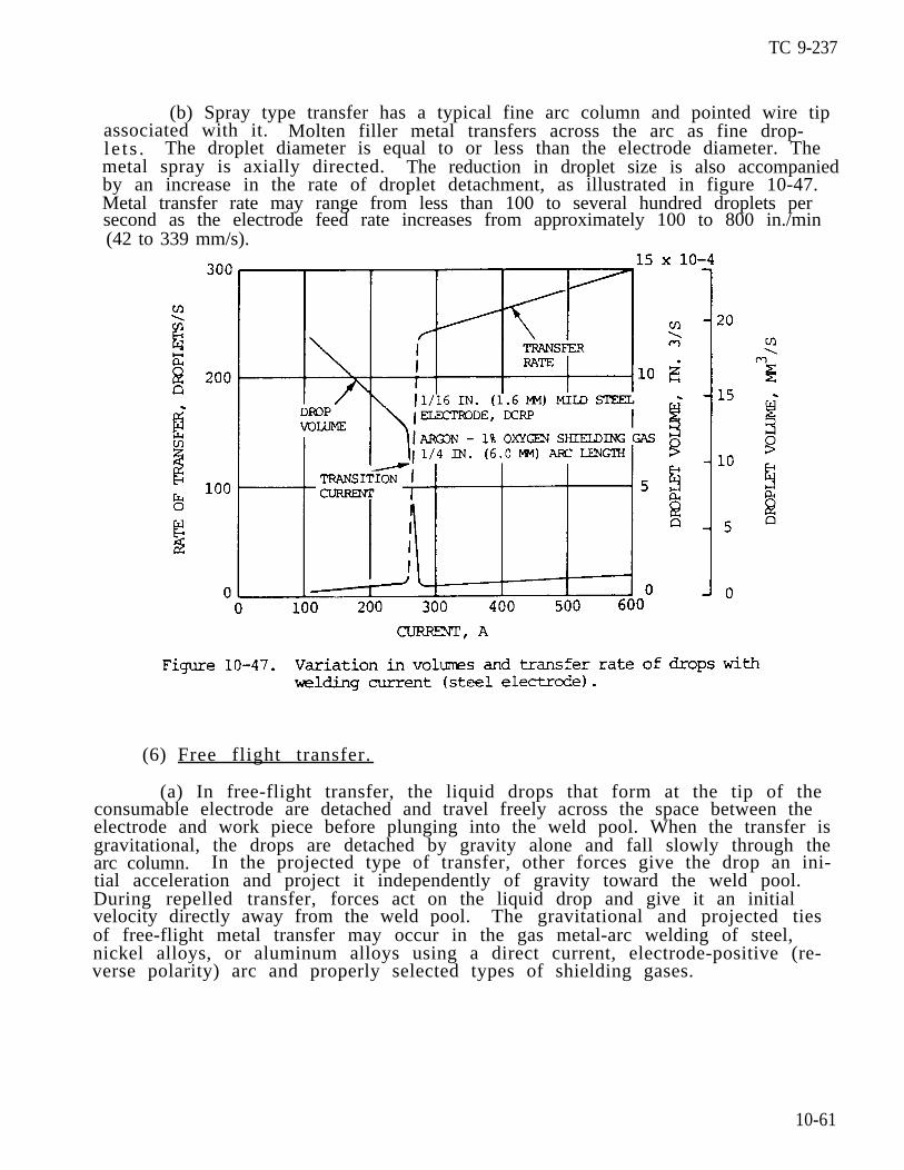
TC 9-237
(b) Spray type transfer has a typical fine arc column and pointed wire tipassociated with it. Molten filler metal transfers across the arc as fine drop-le t s . The droplet diameter is equal to or less than the electrode diameter. Themetal spray is axially directed. The reduction in droplet size is also accompaniedby an increase in the rate of droplet detachment, as illustrated in figure 10-47.Metal transfer rate may range from less than 100 to several hundred droplets persecond as the electrode feed rate increases from approximately 100 to 800 in./min(42 to 339 mm/s).
(6) Free flight transfer.
(a) In free-flight transfer, the liquid drops that form at the tip of theconsumable electrode are detached and travel freely across the space between theelectrode and work piece before plunging into the weld pool. When the transfer isgravitational, the drops are detached by gravity alone and fall slowly through thearc column. In the projected type of transfer, other forces give the drop an ini-tial acceleration and project it independently of gravity toward the weld pool.During repelled transfer, forces act on the liquid drop and give it an initialvelocity directly away from the weld pool. The gravitational and projected tiesof free-flight metal transfer may occur in the gas metal-arc welding of steel,nickel alloys, or aluminum alloys using a direct current, electrode-positive (re-verse polarity) arc and properly selected types of shielding gases.
10-61

TC 9-237
10-12. GAS METAL-ARC WELDING (GMAW OR MIG WELDING) (cont)
(b) At low currents, wires of these alloys melt slowly. A large sphericaldrop forms at the tip and is detached when the force due to gravity exceeds that ofsurface tension. As the current increases, the electromagnetic force becomes sig-nificant and the total. separating force increases. The rate at which drops areformed and detached also increases. At a certain current, a change occurs in thecharacter of the arc and metal transfer. The arc column, previously bell-shaped orspherical and having relatively low brightness, becomes narrower and more conicaland has a bright central core. The droplets that form at the wire tip become elon-gated due to magnetic pressure and are detached at a much higher rate. When carbondioxide is used as the shielding gas, the type of metal transfer is much differ-ent. At low and medium reversed-polarity currents, the drop appears to be repelledfrom the work electrode and is eventually detached while moving away from the work-piece and weld pool. This causes an excessive amount of spatter. At higher cur-rents, the transfer is less irregular because other forces, primarily electrical,overcame the repelling forces. Direct current reversed-polarity is recommended forthe MIG welding process. Straight polarity and alternating current can be used,but require precautions such as a special coating on the electrode wire or specialshield gas mixtures.
(c) The filler wire passes through a copper contact tube in the gun, whereit picks up the welding current. Some manual welding guns contain the wire-drivingmechanism within the gun itself. Other guns require that the wire-feeding mecha-nism be located at the spool of wire, which is some distance from the gun. In thiscase, the wire is driven through a flexible conduit to the welding gun. Anothermanual gun design combines feed mechanisms within the gun and at the wire supplyi t s e l f . Argon is the shielding gas used most often. Small amounts of oxygen (2 to5 percent) frequently are added to the shielding gas when steel is welded. Thisstabilizes the arc and promotes a better wetting action, producing a more uniformweld bead and reducing undercut. Carbon dioxide is also used as a shielding gasbecause it is cheaper than argon and argon-oxygen mixtures. Electrodes designed to be used with carbon dioxide shielding gas require extra deoxidizers in their formu-lation because in the heat of the arc, the carbon dioxide dissociates to carbonmonoxide and oxygen, which can cause oxidation of the weld metal.
(7) Welding parameters. Figures 10-48 through 10-54 show the relationshipbetween the voltage and the current levels , and the type of transfer across thearcs.
10-62


TC 9-237
10-12. GAS METAL-ARC WELDING (GMAW OR MIG WELDING) (cont)
f. Welding Procedures.
(1) The welding procedures for MIG welding are similar to those for other arcwelding processes. Adequate fixturing and clamping of the work are required withadequate accessibility for the welding gun. Fixturing must hold the work rigid tominimize distortion from welding. It should be designed for easy loading and un-loading. Good connection of the work lead (ground) to the workpiece or fixturingis required. Location of the connectio is important, particularly when weldingferromagnetic materials such as steel. The best direction of welding is away fromthe work lead connection. The position of the electrode with respect to the weldjoint is important in order to obtain the desired joint penetration, fusion, andweld bead geometry. Electrode positions for automatic MIG welding are similar tothose used with submerged arc welding.
(2) When complete joint penetration is required, somemethod of weld backingwill help to control it. A backing strip, backing weld, or copper backing bar canbe used. Backing strips and backing welds usually are left in place. Copper back-ing bars are removable.
(3) The assembly of the welding equipnent should be done according to themanufacturer’s directions. All gas and water connections should be tight; thereshould be no leaks. Aspiration of water or air into the shielding gas will resultin erractic arc operation and contamination of the weld. Porosity may also occur.
10-66

TC 9-237
(4) The gun nozzle size and the shielding gas flow rate should be set accord-ing to the recommended welding procedure for the material and joint design to bewelded. Joint designs that require long nozzle-to-work distances will need highergas flow rates than those used with normal nozzle-to-work distances. The gas noz-zle should be of adequate size to provide good gas coverage of the weld area. Whenwelding is done in confined areas or in the root of thick weld joints, small sizenozzles are used.
(5) The gun contact tube and electrode feed drive rolls are selected for theparticular electrode composition and diameter , as specified by the equipment manu-facturer. The contact tube will wear with usage, and must be replaced periodicallyif good electrical contact with electrode is to be maintained and heating of thegun is to be minimized.
(6)tube andwelding,
Electrode extension is set by the distance between the tip of the contactthe gas nozzle opening. The extension used is related to the type of MIGshort circuiting or spray type transfer. It is important to keep the
electrode extension (nozzle-to-work distance) as uniform as-possible during weld-ing . Therefore, depending on the application, the contact tube may be inside,flush with, or extending beyond the gas nozzle.
(7) The electrode feed rate and welding voltage are set to the recommendedvalues for the electrode size and material. With a constant voltage power source,the welding current will be establish by the electrode feed rate. A trial beadweld should be made to establish proper voltage (arc length) and feed rate values.Other variables, such as slope control, inductance, or both, should be adjusted togive good arc starting and smooth arc operation with minimum spatter . The optimumsettings will depend on the equipment design and controls, electrode material andsize, shielding gas, weld joint design, base metal composition and thickness, weld-ing position , and welding speed.
10-67

TC 9-237
10-13. FLUX-CORED
a. General.
ARC WELDING FCAW)
(1) Flux-cored, tubular electrode welding has evolved from the MIG weldingprocess to improve arc action, metal transfer, weld metal properties, and weldappearance. It is an arc welding process in which the heat for welding is providedby an arc between a continuously fed tubular electrode wire and the workpiece.Shielding is obtained by a flux contained within the tubular electrode wire or bythe flux and an externally supplied shielding gas. A diagram of the process isshown in figure 10-55.
(2) Flux-cored arc welding is similar to gas metal arc welding in many ways.The flux-cored wire used for this process gives it different characteristics.Flux-cored arc welding is widely used for welding ferrous metals and is particular-ly good for applications in which high deposition rates are needed. At high weld-ing currents, the arc is smooth and more manageable when compared in using largediameter gas metal arc, welding electrodes with carbon dioxide. The arc and weldpool are clearly visible to the welder. A slag coating is left on the surface ofthe weld bead, which must bearc, some spatter is created
b. Equipment.
(1) The equipment used
removed. Since the filler metal transfers across theand some smoke produced.
for flux-cored arc welding is similar to that used forgas metal arc welding. The basic arc welding equipment consists of a power source,controls, wire feeder, welding gun, and welding cables. A major difference betweenthe gas shielded electrodes and the self -shielded electrodes is that the gas shield-ed wires also require a gas shielding system. This may also have an effect on thetype of welding gun used. Fume extractors are often used with this process. Formachines and automatic welding, several items, such as seam followers and motiondevices, are added to the basic equipment. Figure 10-56 shows a diagram of theequipment used for semiautomatic flux-cored arc welding.
10-68

TC 9-237
(2) The power source, or welding machine, provides the electric power of theproper voltage and amperage to maintain a welding arc. Most power sources operateon 230 or 460 volt input power, but machines that operate on 200 or 575 volt inputare also available. Power sources may operate on either single phase or three-phase input with a frequency of 50 to 60 hertz. Most power sources used for flux-cored arc welding have a duty cycle of 100 percent, which indicates they can beused to weld contiuously. Some machines used for this process have duty cycles of60 percent, which means that they can be used to weld 6 of every 10 minutes. Thepower sources generally recommended for flux-cored arc welding are direct currentconstant voltage type. Both rotating (generator) and static (single or three-phase transformer-rectifiers) are used. The same power sources used with gas metalarc welding are used with flux-cored arc welding. Flux-cored arc welding generallyuses higher welding currents than gas metal arc welding, which sometimes requires alarger power source. It is important to use a power source that is capable ofproducing the maximum current level required for an application.
(3) Flux-cored arc welding uses direct current. Direct current can be eitherreverse or straight polarity. Flux-cored electrode wires are designed to operateon either DCEP or DCEN. The wires designed for use with an external gas shieldingsystem are generally designed for use with DCEP. Some self-shielding flux-coredties are used with DCEP while others are developed for use with DCEN. Electrodepositive current gives better penetration into the weld joint. Electrode negativecurrent gives lighter penetration and is used for welding thinner metal or metalswhere there is poor fit-up. The weld created by DCEN is wider and shallower thanthe weld produced by DCEP.
(4) The generator welding machines used for this process can be powered by anelectric rotor for shop use, or by an internal combustion engine for field applica-t ions. The gasoline or diesel engine-driven welding machines have either liquid-or air-cooled engines. Motor-driven generators produce a very stable arc, but arenoisier, more expensive, consume more power, and require more maintenance thantransformer-rectifier machines.
10-69

TC 9-237
10-13. FLUX-CORED ARC WELDING (FCAW) (cont)
(5) A wire feed motor provides power for driving the electrode through thecable and gun to the work. There are several different wire feeding systems avail-able. System selection depends upon the application. Most of the wire feed sys-tems used for flux-cored arc welding are the constant speed type, which are usedwith constant voltage power sources. With a variable speed wire feeder, a voltagesensing circuit is used to maintain the desired arc length by varying the wire feedspeed. Variations in the arc length increase or decrease the wire feed speed. Awire feeder consists of an electrical rotor connected to a gear box containingdrive rolls. The gear box and wire feed motor shown in figure 10-57 have form feedrolls in the gear box.
.
(6) Both air-cooled and water-cooled guns are used for flux-cored arc weld-ing . Air-cooled guns are cooled primarily by the surrounding air, but a shieldinggas, when used, provides additional cooling effects. A water-cooled gun has ductsto permit water to circulate around the contact tube and nozzle. Water-cooled gunspermit more efficient cooling of the gun. Water-cooled guns are recommended foruse with welding currents greater than 600 amperes , and are preferred for manyapplications using 500 amperes. Welding guns are rated at the maximum currentcapacity for continuous operation. Air-cooled guns are preferred for most applica-tions less than 500 amperes, although water-cooled guns may also be used. Air-cooled guns are lighter and easier to manipulate.
(7) Shielding gas equipment and electrodes.
(a) Shielding gas equipment used for gas shielded flux-cored wires consistsof a gas supply hose, a gas regulator, control valves, and supply hose to the weld-ing gun.
(b) The shielding gases are supplied in liquid form when they are in stor-age tanks with vaporizers, or in a gas form in high pressure cylinders. An excep-tion to this is carbon dioxide. When put in high pressure cylinders, it exists inboth liquid and gas forms.
10-70

TC 9-237
(c) The primary purpose of the shielding gas is to protect the arc and weldpuddle from contaminating effects of the atmosphere. The nitrogen and oxygen ofthe atmosphere, if allowed to come in contact with the molten weld metal, causeporosity and brittleness. In flux-cored arc welding, shielding is accomplished bythe decomposition of the electrode core or by a combination of this and surroundingthe arc with a shielding gas supplied from an external source. A shielding gasdisplaces air in the arc area. Welding is accomplished under a blanket of shield-ing gas. Inert and active gases may both be used for flux-cored arc welding.Active gases such as carbon dioxide, argon-oxygen mixture, and argon-carbon dioxidemixtures are used for almost all applications. Carbon dioxide is the most common.The choice of the proper shielding gas for a specific application is based on thetype of metal to be welded, arc characteristics and metal transfer, availability,cost of the gas, mechanical property requirements, and penetration and weld beadshape. The various shielding gases are summarized below.
1. Carbon dioxide. Carbon dioxide is manufactured from fuel gases whichare given off by the burning of natural gas, fuel oil, or coke. It is also ob-tained as a by-product of calcining operation in lime kilns, from the manufacturingof ammonia and from the fermentation of alcohol, which is almost 100 percentpure. Carbon dioxide is made available to the user in either cylinder or bulkcontainers. The cylinder is more common. With the bulk system, carbon dioxide isusually drawn off as a liquid and heated to the gas state before going to the weld--ing torch. The bulk system is normally only used when supplying a large number ofwelding stations. In the cylinder, the carbon dioxide is in both a liquid and avapor form with the liquid carbon dioxide occupying approximately two thirds of thespace in the cylinder. By weight, this is approximately 90 percent of the contentof the cylinder. Above the liquid, it exists as a vapor gas. As carbon dioxide isdrawn from the cylinder, it is replaced with carbon dioxide that vaporizes from theliquid in the cylinder and therefore the overall pressure will be indicated by thepressure gauge. When the pressure in the cylinder has dropped to 200 psi (1379kPa), the cylinder should be replaced with a new cylinder. A positive pressureshould always be left in the cylinder in order to prevent moisture and other contam-inants from backing up into the cylinder. The normal discharge rate of the CO2
cylinder is about 10 to 50 cu ft per hr (4.7 to 24 liters per min). However, amaximum discharge rate of 25 cu ft per hr (12 liters per min is recommended whenwelding using a single cylinder. As the vapor pressure drops from the cylinderpressure to discharge pressure through the CO2 regulator, it absorbs a great dealof heat. If flow rates are set too high, this absorption of heat can lead to freez-ing of the regulator and flowmeter which interrupts the shielding gas flow. Whenflow rate higher than 25 cu ft per hr (12 liters per rein) is required, normal prac-tice is to manifold two CO2 cylinders in parallel or to place a heater between thecylinder and gas regulator, pressure regulator, and flowmeter. Excessive flowrates can also result in drawing liquid from the cylinder. Carbon dioxide is themost widely used shielding gas for flux-cored arc welding. Most active gases can-not be used for shielding, but carbon dioxide provides several advantages for usein welding steel. These are deep penetration and low cost. Carbon dioxide pro-motes a globular transfer. The carbon dioxide shielding gas breaks down into compo-nents such as carbon monoxide and oxygen. Because carbon dioxide is an oxidizinggas, deoxidizing elements are added to the core of the electrode wire to removeoxygen. The oxides formed by the deoxidizing elements float to the surface of theweld and become part of the slag covering. Some of the carbon dioxide gas willbreak down to carbon and oxygen. If the carbon content of the weld pool is below
10-71
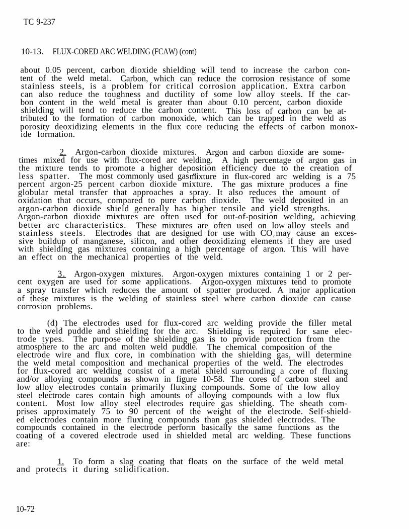
TC 9-237
10-13. FLUX-CORED ARC WELDING (FCAW) (cont)
about 0.05 percent, carbon dioxide shielding will tend to increase the carbon con-tent of the weld metal. Carbon, which can reduce the corrosion resistance of somestainless steels, is a problem for critical corrosion application. Extra carboncan also reduce the toughness and ductility of some low alloy steels. If the car-bon content in the weld metal is greater than about 0.10 percent, carbon dioxideshielding will tend to reduce the carbon content. This loss of carbon can be at-tributed to the formation of carbon monoxide, which can be trapped in the weld asporosity deoxidizing elements in the flux core reducing the effects of carbon monox-ide formation.
2. Argon-carbon dioxide mixtures. Argon and carbon dioxide are some-times mixed for use with flux-cored arc welding. A high percentage of argon gas inthe mixture tends to promote a higher deposition efficiency due to the creation ofless spatter. The most commonly used gas “mixture in flux-cored arc welding is a 75percent argon-25 percent carbon dioxide mixture. The gas mixture produces a fineglobular metal transfer that approaches a spray. It also reduces the amount ofoxidation that occurs, compared to pure carbon dioxide. The weld deposited in anargon-carbon dioxide shield generally has higher tensile and yield strengths.Argon-carbon dioxide mixtures are often used for out-of-position welding, achievingbetter arc characteristics. These mixtures are often used on loW alloy steels andstainless steels. Electrodes that are designed for use with CO2 may cause an exces-sive buildup of manganese, silicon, and other deoxidizing elements if they are usedwith shielding gas mixtures containing a high percentage of argon. This will havean effect on the mechanical properties of the weld.
3. Argon-oxygen mixtures. Argon-oxygen mixtures containing 1 or 2 per-cent oxygen are used for some applications. Argon-oxygen mixtures tend to promotea spray transfer which reduces the amount of spatter produced. A major applicationof these mixtures is the welding of stainless steel where carbon dioxide can causecorrosion problems.
(d) The electrodes used for flux-cored arc welding provide the filler metalto the weld puddle and shielding for the arc. Shielding is required for sane elec-trode types. The purpose of the shielding gas is to provide protection from theatmosphere to the arc and molten weld puddle. The chemical composition of theelectrode wire and flux core, in combination with the shielding gas, will determinethe weld metal composition and mechanical properties of the weld. The electrodesfor flux-cored arc welding consist of a metal shield surrounding a core of fluxingand/or alloying compounds as shown in figure 10-58. The cores of carbon steel andlow alloy electrodes contain primarily fluxing compounds. Some of the low alloysteel electrode cares contain high amounts of alloying compounds with a low fluxcontent. Most low alloy steel electrodes require gas shielding. The sheath com-prises approximately 75 to 90 percent of the weight of the electrode. Self-shield-ed electrodes contain more fluxing compounds than gas shielded electrodes. Thecompounds contained in the electrode perform basically the same functions as thecoating of a covered electrode used in shielded metal arc welding. These functionsare:
1. To form a slag coating that floats on the surface of the weld metaland protects it during solidification.
10-72

TC 9-237
2. To provide deoxidizers and scavengers which help purify and producesolid weld-metal.
3. To provide arc stabilizers which produce a smooth welding arc andkeep spatter to a minimum.
4. To add alloying elements to the weld metal which will increase thestrength and improve other properties in the weld metal.
5. To provide shielding gas. Gas shielded wires require an externalsupply of shielding gas to supplement that produced by the core of the electrode.
(e) The classification system used for tubular wire electrodes was devisedby the American Welding Society. Carbon and low alloy steels are classified on thebasis of the following items:
1 . Mechanical properties of the weld metal.
2 . Welding position.
3. Chemical composition of the weld metal.
4. Type of welding current.
5. Whether or not a CO2 shielding gas is used.
An example of a carbon steel electrode classification is E70T-4 where:
1 . The “E” indicates an electrode.
2. The second digit or “7“ indicates the minimum tensile strength in units of 10,000 psi (69 MPa). Table 10-12, p 10-74, shows the mechanical propertyrequirements for the various carbon steel electrodes.
3. The third digit or “0” indicates the welding positions. A “0” indi-cates flat and horizontal positions and a “1” indicates all positions.
10-73

TC 9-237
10-13. FLUX-CORED ARC WELDING (FCAW) (cont)
4. The “T” stands for a tubular or flux cored wire classification.
5. The suffix “4” gives the performance and usability capabilities asshown in table 10-13. When a “G” classification is used, no specific performanceand usability requirements are indicated. This classification is intended forelectrodes not covered by another classification. The chemical composition require-ments of the deposited weld metal for carbon steel electrodes are shown in table10-14. Single pass electrodes do not have chemical composition requirements be-cause checking the chemistry of undiluted weld metal does not give the true resultsof normal single pass weld chemistry.
10-74

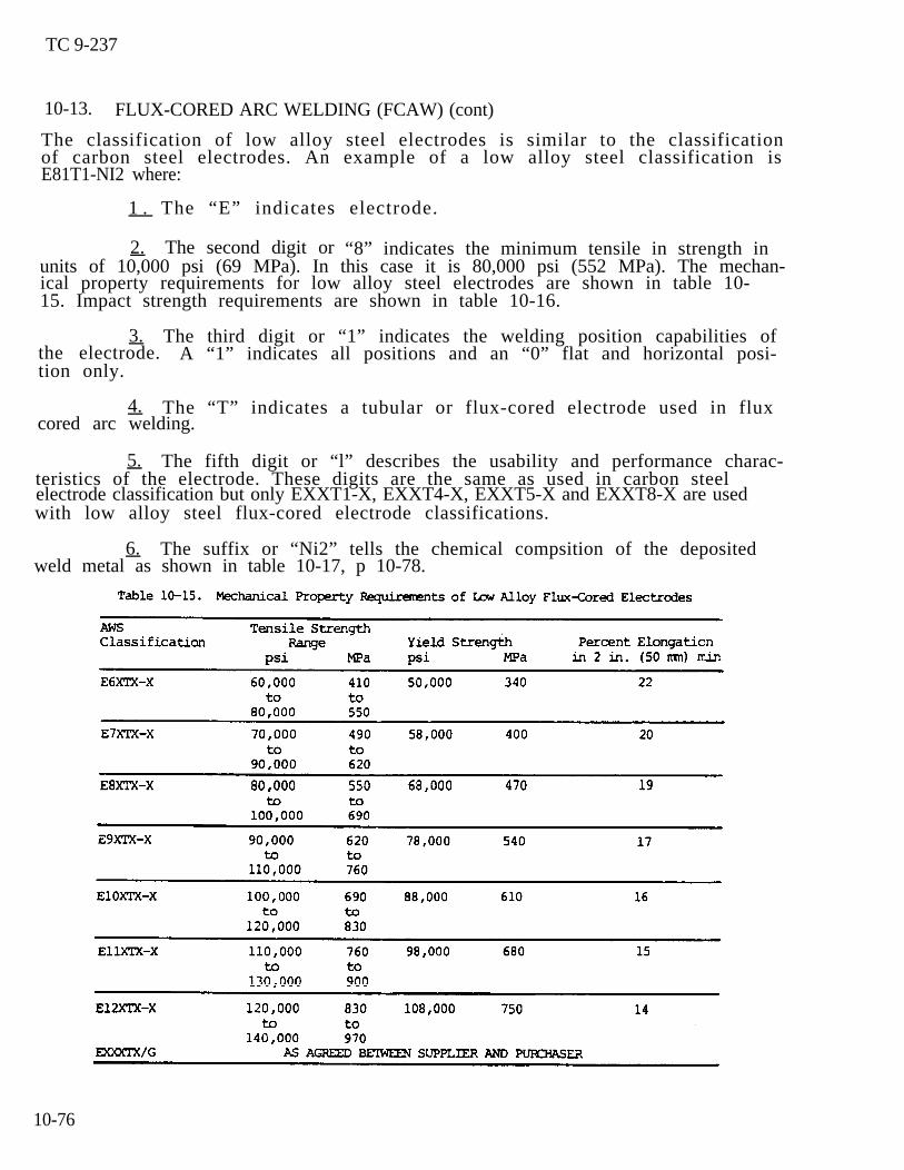
TC 9-237
10-13. FLUX-CORED ARC WELDING (FCAW) (cont)
The classification of low alloy steel electrodes is similar to the classificationof carbon steel electrodes. An example of a low alloy steel classification isE81T1-NI2 where:
1 . The “E” indicates electrode.
2. The second digit or “8” indicates the minimum tensile in strength inunits of 10,000 psi (69 MPa). In this case it is 80,000 psi (552 MPa). The mechan-ical property requirements for low alloy steel electrodes are shown in table 10-15. Impact strength requirements are shown in table 10-16.
3. The third digit or “1” indicates the welding position capabilities ofthe electrode. A “1” indicates all positions and an “0” flat and horizontal posi-tion only.
4. The “T” indicates a tubular or flux-cored electrode used in fluxcored arc welding.
5. The fifth digit or “l” describes the usability and performance charac-teristics of the electrode. These digits are the same as used in carbon steelelectrode classification but only EXXT1-X, EXXT4-X, EXXT5-X and EXXT8-X are usedwith low alloy steel flux-cored electrode classifications.
6. The suffix or “Ni2” tells the chemical compsition of the depositedweld metal as shown in table 10-17, p 10-78.
10-76


TC 9-237
The classification system for stainless steel electrodes is based on the chemicalcomposition of the weld metal and the type of shielding to be employed during weld-ing. An example of a stainless steel electrode classification is E308T–1 where:
1. The “E” indicates the electrode.2. The digits between the “E” and the “T” indicates the chemical composi-
tion of the weld as shown in table 10-18, p 10-80.3. The “T” designates a tubular or flux cored electrode wire.4 . The suffix of “1” indicates the type of shielding to be used as shown
in table 10-19, p 10-81.
10-79

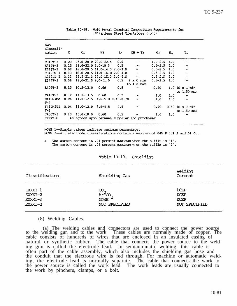
TC 9-237
(8) Welding Cables.
(a) The welding cables and connectors are used to connect the power sourceto the welding gun and to the work. These cables are normally made of copper. Thecable consists of hundreds of wires that are enclosed in an insulated casing ofnatural or synthetic rubber. The cable that connects the power source to the weld-ing gun is called the electrode lead. In semiautomatic welding, this cable isoften part of the cable assembly, which also includes the shielding gas hose andthe conduit that the electrode wire is fed through. For machine or automatic weld-ing, the electrode lead is normally separate. The cable that connects the work tothe power source is called the work lead. The work leads are usually connected tothe work by pinchers, clamps, or a bolt.
10-81

TC 9-237
10-13. FLUX-CORED ARC WELDING (FCAW) (cont)
(b) The size of the welding cablesthe welding machine, the duty cycle of thewelding machine and the work. Cable sizesNo 4/0 with amperage ratings of 75 amperescable sizes for use with different welding
used depends on the output capacity ofmachine, and the distance between therange from the smallest AWG No 8 to AWGon up. Table 10-20 shows recommendedcurrents and cable lengths. A cable
that is too small may become too hot during welding.
c. Advantages. The major advantages of flux-cored welding are reduced cost andhigher deposition rates than either SMAW or solid wire GMAW. The cost is less forflux-cored electrodes because the alloying agents are in the flux, not in the steelfiller wire as they are with solid electrodes. Flux-cored welding is ideal wherebead appearance is important and no machining of the weld is required. Flux-coredwelding without carbon dioxide shielding can be used for most mild steel construc-tion applications. The resulting welds have higher strength but less ductilitythan those for which carbon dioxide shielding is used. There is less porosity andgreater penetration of the weld with carbon dioxide shielding. The flux-coredprocess has increased tolerances for scale and dirt. There is less weld spatterthan with solid-wire MIG welding. It has a high deposition rate, and faster travelspeeds are often used. Using small diameter electrode wires, welding can be donein all positions. Some flux-cored wires do not need an external supply of shield-ing gas, which simplifies the equipment. The electrode wire is fed continuouslyso there is very little time spent on changing electrodes. A higher percentage ofthe filler metal is deposited when compared to shield metal arc welding. Finally,better penetration is obtained than from shielded metal arc welding.
d. Disadvantages. Most low-alloy or mild-steel electrodes of the flux-coredtype are more sensitive to changes in welding conditions than are SMAW electrodes.This sensitivity, called voltage tolerance, can be decreased if a shielding gas isused, or if the slag-forming components of the core material are increased. Aconstant-potential power source and constant-speed electrode feeder are needed tomaintain a constant arc voltage.
10-82

TC 9-237
e. Process Principles. The flux-cored welding wire, or electrode, is a hollowtube filled with a mixture of deoxidizers, fluxing agents, metal powders, andferro-alloys. The closure seam, which appears as a fine line, is the only visibledifference between flux-cored wires and solid cold-drawn wire. Flux-cored elec-trode welding can be done in two ways: carbon dioxide gas can be used with. theflux to provide additional shielding, or the flux core alone can provide all theshielding gas and slagging materials. The carbon dioxide gas shield produces adeeply penetrating arc and usually provides better weld than is possible without anexternal gas shield. Although flux-cored arc welding may be applied semiautomati–tally, by machine, or automatically, the process is usually applied semiautomatical-ly. In semiautomatic welding, the wire feeder feeds the electrode wire and thepower source maintains the arc length. The welder manipulates the welding gun andadjusts the welding parameters. Flux-cored arc welding is also used in machinewelding where, in addition to feeding the wire and maintaining the arc length, themachinery also provides the joint travel. The welding operator continuously moni–tors the welding and makes adjustments in the welding parameters. Automatic weld-ing is used in high production applications.
10-14. SUBMERGED ARC WELDING (SAW)
a. General. Submerged arc welding is a process in which the joining of metalsis produced by heating with an arc or arcs between a bare metal electrode or elec–trodes and the work. The arc is shielded by a blanket of granular fusible materialon the work. Pressure is not used. Filler metal is obtained from the electrode orfrom a supplementary welding rod.
b. Equipment.
(1) The equipment components required for submerged arc welding are shown byfigure 10-59. Equipment consists of a welding machine or power source, the wirefeeder and control system, the welding torch for automatic welding or the weldinggun and cable assembly for semiautomatic welding, the flux hopper and feeding mecha-nism, usually a flux recovery system, and a travel mechanism for automatic welding.
10-83

TC 9-237
10-14. SUBMERGED ARC WELDING (SAW) (cont)
(2) The power source for submerged arc welding must be rated for a 100 per-cent duty cycle, since the submerged arc welding operations are continuous and thelength of time for making a weld may exceed 10 minutes. If a 60 percent duty cyclepower source is used, it must be derated according to the duty cycle curve for 100percent operation.
(3) When constant current is used, either ac or dc, the voltage sensing elec-trode wire feeder system must be used. When constant voltage is used, the simplerfixed speed wire feeder system is used. The CV system is only used with directcurrent.
(4) Both generator and transformer-rectifier power sources are used, but therectifier machines are more popular. Welding machines for submerged arc weldingrange in size from 300 amperes to 1500 amperes. They may be connected in parallelto provide extra power for high—current applications. Direct current power is usedfor semiautomatic applications, but alternating current power is used primarilywith the machine or the automatic method. Multiple electrode systems require spe-cialized types of circuits, especially when ac is employed.
(5) For semiautomatic application, a welding gun and cable assembly are used to carry the electrode and current and to provide the flux at the arc. A smallflux hopper is attached to the end of the cable assembly. The electrode wire isfed through the bottom of this flux hopper through a current pickup tip to the arc. The flux is fed from the hopper to the welding area by mans of gravity. Theamount of flux fed depends on how high the gun is held above the work. The hoppergun may include a start switch to initiate the weld or it may utilize a “hot” elec-trode so that when the electrode is touched to the work, feeding will begin automat-ically.
(6) For automatic welding, the torch is attached toincludes current pickup tips for transmitting the weldingwire. The flux hopper is normally attached to the torch,
.
the wire feed motor andcurrent to the electrodeand may have magnetically
operated valves which can be opened or closed by the control system.
(7) Other pieces of equipment sometimes used may include a travel carriage,which can be a simple tractor or a complex moving specialized fixture. A fluxrecovery unit is normally provided to collect the unused submerged arc flux andreturn it to the supply hopper.
(8) Submerged arc welding system can become quite complex by incorporatingadditional devices such as seam followers, weavers, and work rovers.
c. Advantages and Major Uses.
(1) The major advantages of the submerged arc welding process are:
(a) high quality of the weld metal.(b) extremely high deposition rate and speed.(c) smooth, uniform finished weld with no spatter.(d) little or no smoke.(e) no arc flash, thus minimal need for protective clothing.(f) high utilization of electrode wire.(g) easy automation for high-operator factor.(h) normally, no involvement of manipulative skills.
10-84

TC 9-237
(2) The submerged arc process is widely used in heavy steel plate fabricationwork. This includes the welding of structural shapes, the longitudinal seam oflarger diameter pipe, the manufacture of machine components for all types of heavyindustry, and the manufacture of vessels and tanks for pressure and storage use.It is widely used in the shipbuilding industry for splicing and fabricating subas-semblies, and by many other industries where steels are used in medium to heavythicknesses. It is also used for surfacing and buildup work, maintenance, andrepair.
d. Limitations of the Process.(1) A major limitation of submerged arc welding is
positions. The other limitation is that it is primarilylow-alloy high-strength steels.
(2) The high-heat input, slow-cooling cycle can bequenched and tempered steels. The heat input limitation
its limitation of weldingused only to weld mild and
a problem when weldingof the steel in question
must be strictly-adhered to when using submerged arc welding. This may require themaking of multipass welds where a single pass weld would be acceptable in mildsteel . In some cases, the economic advantages may be reduced to the point whereflux-cored arc welding or some other process should be considered.
(3) In semiautomatic submerged arc welding, the inability to see the arc andpuddle can be a disadvantage in reaching the root of a groove weld and properlyfilling or sizing.
e. Principles of Operation.
(1) The submerged arc welding process is shown by figure 10-60. It utilizesthe heat of an arc between a continuously fed electrode and the work. The heat ofthe arc melts the surface of the base metal and the end of the electrode. Themetal melted off the electrode is transferred through the arc to the workpiece,where it becomes the deposited weld metal. Shielding is obtained from a blanket ofgranular flux , which is laid directly over the weld area. The flux close to thearc melts and intermixes with the molten weld metal, helping to purify and fortifyi t . The flux forms a glass-like slag that is lighter in weight than the depositedweld metal and floats on the surface as a protective cover. The weld is submergedunder this layer of flux and slag, hence the name submerged arc welding. The fluxand slag normally cover the arc so that it is not visible. The unmelted portion ofthe flux can be reused. The electrode is fed into the arc automatically from acoi l . The arc is maintained automatically. Travel can be manual or by machine.The arc is initiated by a fuse type start or by a reversing or retrack system.
10-85

TC 9-237
10-14. SUBMERGED ARC WELDING (SAW) (cont)
(2) Normal method of application and position capabilities. The most popularmethod of application is the machine method, where the operator monitors the weld-ing operation. Second in popularity is the automatic method, where welding is apushbutton operation. The process can be applied semiautomatically; however, thismethod of application is not too popular. The process cannot be applied manuallybecause it is impossible for a welder to control an arc that is not visible. Thesubmerged arc welding process is a limited-position welding process. The weldingpositions are limited because the large pool of molten metal and the slag are veryfluid and will tend to run out of the joint. Welding can be done in the flat posi-tion and in the horizontal fillet position with ease. Under special controlledprocedures, it is possible to weld in the horizontal position, sometimes called 3o' clock welding. This requires special devices to hold the flux up so that themolten slag and weld metal cannot run away. The process cannot be used in thevertical or overhead position.
(3) Metals weldable and thickness range. Submerged arc welding is used toweld low- and medium-carbon steels, low-alloy high-strength steels, quenched andtempered steels, and many stainless steels. Experimentally, it has been used toweld certain copper alloys, nickel alloys, and even uranium. This information issummarized in table 10-21.
Metal thicknesses from 1/16 to 1/2 in. (1.6 to 12.7 mm) can be welded with no edgepreparation. With edge preparation, welds can be made with a single pass on materi-al from 1/4 to 1 in. (6.4 to 25.4 mm). When multipass technique is used, the maxi-mum thickness is practically unlimited. This information is summarized in table10-22. Horizontal fillet welds can be made up to 3/8 in. (9.5 mm) in a single passand in the flat position, fillet welds can be made up to 1 in. (25 mm) size.
10-86

TC 9-237
(4) Joint design. Although the submerged arc welding process can utilize thesame joint design details as the shielded metal arc welding process, differentjoint details are suggested for maximum utilization and efficiency of submerged arcwelding . For groove welds, the square groove design can be used up to 5/8 in. (16mm) thickness. Beyond this thickness, bevels are required. Open roots are usedbut backing bars are necessary since the molten metal will run through the joint.When welding thicker metal, if a sufficiently large root face is used, the backingbar may be eliminate. However, to assure full penetration when welding from oneside, backing bars are recommended. Where both sides are accessible, a backingweld can be made which will fuse into the original weld to provide full penetra-tion. Recommended submerged arc joint designs are shown by figure 10-61, p 10-88.
(5) Welding circuit and current.
(a) The welding circuit employedis shown by figure 10-59, p 10-83. Thissupply.
for single electrode submerged arc weldingrequires a wire feeder system and a power
(b) The submerged arc welding process uses either direct or alternatingcurrent for welding power. Direct current is used for most applications which usea single arc. Both direct current electrode positive (DCEP) and electrode negative(DCEN) are used.
(c) The constant voltage type of direct current power is more popular forsubmerged arc we welding with 1/8 in. (3.2 mm) and smaller diameter electrode negative
(d) The constant current power system is normally used for welding with5/3 2 in. (4 mm) and larger-diameter electrode wires. The control circuit for CCpower is more complex since it attempts to duplicate the actions of the welder toretain a specific arc length. The wire feed system must sense the voltage acrossthe arc and feed the electrode wire into the arc to maintain this voltage. Asconditions change, the wire feed must slow down or speed up to maintain the pre-fixed voltage across the arc. This adds complexity to the control system. Thesystem cannot react instantaneously. Arc starting is mare complicated with theconstant current system since it requires the use of a reversing system to strikethe arc, retract, and then maintain the preset arc voltage.
10-87


TC 9-237
(e) For ac welding, the constant current power is always used. when multi-ple electrode wire systems are used with both ac and dc arcs, the constant currentpower system is utilized. The constant voltage system, however, can be appliedwhen two wires are fed into the arc supplied by a single power source. Weldingcurrent for submerged arc welding can vary from as low as 50 amperes to as high as2000 amperes. Most submerged arc welding is done in the range of 200 to 1200 am-peres.
10-89

TC 9-237
10-14. SUBMERGED ARC WELDING (cont)
(6) Deposition rates and weld quality.
(a) The deposition rates of the submerged arc welding process are higherthan any other arc welding process. Deposition rates for single electrodes areshown by figure 10-62. There are at least four related factors that control thedeposition rate of submerged arc welding: polarity, long stickout, additives inthe flux, and additional electrodes. The deposition rate is the highest for directcurrent electrode negative (DCEN). The deposition rate for alternating current isbetween DCEP and DCEN. The polarity of maximum heat is the negative pole.
(b) The deposition rate with any welding current can be increased by extend-ing the “stickout.” This is the distance from the point where current is intro-duced into the electrode to the arc. When using “long stickout” the amount ofpenetration is reduced. The deposition rates can be increased by metal additivesin the submerged arc flux. Additional electrodes can be used to increase the over-all deposition rate.
(c) The quality of the weld metal deposited by the submerged arc weldingprocess is high. The weld metal strength and ductility exceeds that of the mildsteel or low-alloy base material when the correct combination of electrode wire andsubmerged arc flux is used. When submerged arc welds are made by machine or auto-matically, the human factor inherent to the manual welding processes is eliminated.The weld will be more uniform and free from inconsistencies. In general, the weldbead size per pass is much greater with submerged arc welding than with any of theother arc welding processes. The heat input is higher and cooling rates are slow-er. For this reason, gases are allowed more time to escape. Additionally, sincethe submerged arc slag is lower in density than the weld metal, it will float outto the top of the weld. Uniformity and consistency are advantages of this processwhen applied automatically.
10-90
TC 9-237
(d) Several problems may occur when using the semiautomatic applicationmethod. The electrode wire may be curved when it leaves the nozzle of the weldinggun. This curvature can cause the arc to be struck in a location not expected bythe welder. When welding in fairly deep grooves, the curvature may cause the arcto be against one side of the weld joint rather than at the root. This will causeincomplete root fusion. Flux will be trapped at the root of the weld. Anotherproblem with semiautomatic welding is that of completely filling the weld groove ormaintaining exact size, since the weld is hidden and cannot be observed while it isbeing made. This requires making an extra pass. In some cases, too much weld isdeposited. Variations in root opening affect the travel speed. If travel speed isuniform, the weld may be under- or overfilled in different areas. High operatorskill will overcome this problem.
(e) There is another quality problem associated with extremely largesingle-pass weld deposits. When these large welds solidify, the impurities in themelted base metal and in the weld metal all collect at the last point to freeze,which is the centerline of the weld. If there is sufficient restraint and enoughimpurities are collected at this point, centerline cracking may occur. This canhappen when making large single-pass flat fillet welds if the base metal plates are4 50from flat. A simple solution is to avoid placing the parts at a true 450
angle. It should be varied approximately 10 so that the root of the joint is notin line with the centerline of the fillet weld. Another solution is to make multi-ple passes rather than attempting to make a large weld in a single pass.
(f) Another quality problem has to do with the hardness of the depositedweld metal . Excessively hard weld deposits contribute to cracking of the weldduring fabrication or during service. A maximum hardness level of 225 Brinell isrecommended. The reason for the hard weld in carbon and low-alloy steels is toorapid cooling, inadequate postweld treatment, or excessive alloy pickup in the weldmetal. Excessive alloy pickup is due to selecting an electrode that has too muchalloy, selecting a flux that introduces too much alloy into the weld, or the use ofexcessively high welding voltages.
(g) In automatic and machine welding, defects may occur at the start or atthe end of the weld. The best solution is to use runout tabs so that S tartS a n dstops will be on the tabs rather than on the product.
(7) Weld schedules. The submerged arc welding process applied by machine orfully automatically should be done in accordance with welding procedure schedules.Table 10-23, p 10-93, and figure 10-63, p 10-92, show the recommended welding sched-ules for submerged arc welding using a single electrode on mild and low-alloysteels. The table can be used for welding other ferrous materials, but was devel-oped for mild steel. All of the welds made by this procedure should pass qualifica-tion, tests, assuming that the correct electrode and flux have been selected. Ifthe schedules are varied more than 10 percent, qualification tests should be per-formed to determine the weld quality.
10-91
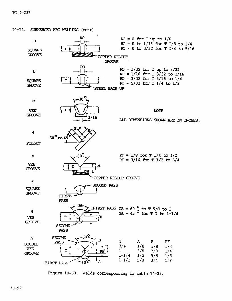


TC 9-237
(8) Welding variables.
(a) The welding variablesother arc welding processes, with
for submerged arc welding are similar to theseveral exceptions.
(b) In submerged arc welding, the electrode type and the flux type areusually based on the mechanical properties required by the weld. The electrode andflux combination selection is based on table 10-24, p 10-103, to match the metalbeing welded. The electrode size is related to the weld joint size and the currentrecommended for the particular joint. This must also be considered in determiningthe number of passes or beads for a particular joint. Welds for the same jointdimension can be made in many or few passes, depending on the weld metal metallurgydesired. Multiple passes usually deposit higher-quality weld metal. Polarity isestablished initially and is based on whether maximum penetration or maximum deposi–tion rate is required.
(c) The major variables that affect the weld involve heat input and includethe welding current, arc voltage, and travel speed. Welding current is the mostimportant. For single-pass welds, the current should be sufficient for the desiredpenetration without burn-through. The higher the current, the deeper the penetra-tion. In multi-pass work, the current should be suitable to produce the size ofthe weld expected in each pass. The welding current should be selected based onthe electrode size. The higher the welding current, the greater the melt-off rate(deposition rate).
(d) The arc voltage is varied within narrower limits than welding current.It has an influence on the bead width and shape. Higher voltages will cause thebead to be wider and flatter. Extremely high arc voltage should be avoided, sinceit can cause cracking. This is because an abnormal amount of flux is melted andexcess deoxidizers may be transferred to the weld deposit, lowering its ductility.Higher arc voltage also increases the amount of flux consumed. The low arc voltageproduces a stiffer arc that improves penetration, particularly in the bottom ofdeep grooves. If the voltage is too low, a very narrow bead will result. It willhave a high crown and the slag will be difficult to remove.
(e) Travel speed influences both bead width and penetration. Faster travelspeeds produce narrower beads that have less penetration. This can be an advantagefor sheet metal welding where small beads and minimum penetration are required. Ifspeeds are too fast, however, there is a tendency for undercut and porosity, sincethe weld freezes quicker. If the travel speed is too slow, the electrode stays inthe weld puddle too long. This creates poor bead shape and may cause excessivespatter and flash through the layer of flux.
10-95

TC 9-237
10-14. SUBMERGED ARC WELDING (cont)
(f) The secondary variables include the angle of the electrode to the work,the angle of the work itself, the thickness of the flux layer, and the distancebetween the current pickup tip and the arc. This latter factor, called electrode“stickout,“ has a considerable effect on the weld. Normally, the distance betweenthe contact tip and the work is 1 to 1-1/2 in. (25 to 38 mm). If the stickout isincreased beyond this amount, it will cause preheating of the electrode wire, whichwill greatly increase the deposition rate. As stickout increases, the penetrationinto the base metal decreases. This factor must be given serious considerationbecause in some situations the penetration is required. The relationship betweenstickout and deposition rate is shown by figure 10-64.
(g) The depth of the flux layer must also be considered. If it is toothin, there will be too much arcing through the flux or arc flash. This also maycause porosity. If the flux depth is too heavy, the weld may be narrow andhumped. Too many small particles in the flux can cause surface pitting since thegases generated in the weld may not be allowed to escape. These are sometimescalled peck marks on the bead surface.
10-96

TC 9-237
(9) Tips for using the process.
(a) One of the major applications for submerged arc welding is on circularwelds where the parts are rotated under a fixed head. These welds can be made onthe inside or outside diameter. Submerged arc welding produces a large molten weld.puddle and molten slag which tends to run. This dictates that on outside diame-ters, the electrode should be positioned ahead of the extreme top, or 12 o'clockposition, so that the weld metal will begin to solidify before it starts thedownside slope. This becomes more of a problem as the diameter of the part beingwelded gets smaller. Improper electrode position will increase the possibility ofslag entrapment or a poor weld surface. The angle of the electrode should also bechanged and pointed in the direction of travel of the rotating part. When thewelding is done on the inside circumference, the electrode should be angled so thatit is ahead of bottom center, or the 6 o'clock position. Figure 10-65 illustratesthese two conditions.
(b) Sometimes the work being welded is sloped downhill or uphill to providedifferent types of weld bead contours. If the work is sloped downhill, the beadwill have less penetration and will be wider. If the weld is sloped uphill, thebead will have deeper penetration and will be narrower. This is based on all otherfactors remaining the same. This information is shown by figure 10-66.
10-97

TC 9-237
10-14. SUBMERGED ARC WELDING (cont)
(c) The weld will be different depending on the angle of the electrode withrespect to the work when the work is level. This is the travel angle, which can bea drag or push angle. It has a definite effect on the bead contour and weld metalpenetration. Figure 10-67 shows the relationship.
(d) One side welding with complete root penetration can be obtained withsubmerged arc welding. When the weld joint is designed with a tight root openingand a fairly large root face, high current and electrode positive should be used.If the joint is designed with a root opening and a minimum root face, it is neces-sary to use a backing bar, since there is nothing to support the molten weld met-a l . The molten flux is very fluid and will run through narrow openings. If thishappens, the weld metal will follow and the weld will burn through the joint.Backing bars are needed whenever there is a root opening and a minimum root face.
(e) Copper backing bars are useful when welding thin steel. Without back-ing bars, the weld would tend to melt through and the weld metal would fall awayfrom the joint. The backing bar holds the weld metal in place until it solidi-f ies . The copper backing bars may be water cooled to avoid the possibility ofmelting and copper pickup in the weld metal. For thicker materials, the backingmay be submerged arc flux or other specialized type flux.
(10) Variations of the process.
(a) There are a large number of variations to the process that give sub-merged arc welding additional capabilities. Some of the more popular variationsare:
1.
2.
3.
4.
5.
6.
7.
Two-wire systems — same power source.
Two-wire systems — separate power source.
Three-wire systems — separate power source.
Strip electrode for surfacing.
Iron powder additions to the flux.
Long stickout welding.
Electrically “cold” filler wire.
10-98

TC 9-237
(b) The multi-wire systems offer advantages since deposition rates and trav-el speeds can be improved by using more electrodes. Figure 10-68 shows the twomethods of utilizing two electrodes, one with a single-power source and one withtwo power sources. When a single-power source is used, the same drive rolls areused for feeding both electrodes into the weld. When two power sources are used,individual wire feeders must be used to provide electrical insulation between thetwo electrodes. With two electrodes and separate power, it is possible to utilizedifferent polarities on the two electrodes or to utilize alternating current on oneand direct current on the other. The electrodes can be placed side by side. Thisis called transverse electrode position. They can also be placed one in front ofthe other in the tandem electrode position.
(c) The two-wire tandem electrode position with individual power sources isused where extreme penetration is required. The leading electrode is positive withthe trailing electrode negative. The first electrode creates a digging action andthe second electrode fills the weld joint. When two dc arcs are in close proximi-ty, there is a tendency for arc interference between them. In some cases, thesecond electrode is connected to alternating current to avoid the interaction ofthe arc.
10-99

TC 9-237
10-14. SUBMERGED ARC WELDING (SAW) (cont)
(d) The three-wire tandem system normally uses ac power on all three elec-trodes connected to three-phase power systems. These systems are used for makinghigh-speed longitudinal seams for large-diameter pipe and for fabricated beams.Extremely high currents can be used with correspondingly high travel speeds anddeposition rates.
(e) The strip welding system is used to overlay mild and alloy steels usual-ly with stainless steel. A wide bead is produced that has a uniform and minimumpenetration. This process variation is shown by figure 10-69. It is used foroverlaying the inside of vessels to provide the corrosion resistance of stainlesssteel while utilizing the strength and economy of the low-alloy steels for the wallthickness. A strip electrode feeder is required and special flux is normallyused . When the width of the strip is over 2 in. (51 mm), a magnetic arc oscillat-ing device is used to provide for even burnoff of the strip and uniform penetration.
(f) Another way of increasing the deposition rate of submerged arc weldingis to add iron base ingredients to the joint under the flux. The iron in thismaterial will melt in the heat of the arc and will become part of the depositedweld metal. This increases deposition rates without decreasing weld metal proper-t ies . Metal additives can also be used for special surfacing applications. Thisvariation can be used with single-wire or multi-wire installations. Figure 10-70shins the increased deposition rates attainable.
10-100

TC 9-237
(g) Another variation is the use of an electrically “cold” filler wire fedinto the arc area. The “cold” filler rod can be solid or flux-cored to add specialalloys to the weld metal. By regulating the addition of the proper material, theproperties of the deposited weld metal can be improved. It is possible to utilizea flux-cored wire for the electrode, or for one of the multiple electrodes to intro-duce special alloys into the weld metal deposit. Each of these variations requiresspecial engineering to ensure that the proper material is added to provide thedesired deposit properties.
(11) Typical applications. The submerged arc welding process is widely usedin the manufacture of most heavy steel products. These include pressure vessels,boilers, tanks, nuclear reactors, chemical vessels, etc.fabrication of trusses and beams. It is used for weldingheavy equipment industry is a major user of submerged arc
Another use is in theflanges to the web. Thewelding.
f . Materials Used.
(1) Two materials are used in submerged arc welding: the welding flux andthe consumable electrode wire.
(2) Submerged arc welding flux shields the arc and the molten weld metal fromthe harmful effects of atmospheric oxygen and nitrogen. The flux containsdeoxidizers and scavengers which help to remove impurities from the molten weldmetal. Flux also provides a means of introducing alloys into the weld metal. Asthis molten flux cools to a glassy slag, it forms a covering which protects thesurface of the weld. The unmelted portion of the flux does not change its form andits properties are not affected, so it can be recovered and reused. The flux thatdoes melt and forms the slag covering must be removed from the weld bead. This iseasily done after the weld has cooled. In many cases, the slag will actually peelwithout requiring special effort for removal. In groove welds, the solidified slagmay have to be removed by a chipping hammer.
10-101

TC 9-237
10-14. SURMERGED ARC WELDING (cont)
(3) Fluxes are designed for specific applications and for specific types ofweld deposits. Submerged arc fluxes come in different particle sizes. Many fluxesare not marked for size of particles because the size is designed and produced forthe intended application.
(4) There is no specification for submerged arc fluxes in use in North Ameri-ca. A method of classifying fluxes, however, is by means of the deposited weldmetal produced by various combinations of electrodes and proprietary submerged arcfluxes. This is covered by the American Welding Society Standard. Bare carbonsteel electrodes and fluxes for submerged arc welding. In this way, fluxes can bedesignated to be used with different electrodes to provide the deposited weld metal analysis that is desired. Table 10-24 shows the flux wire combination and themechanical properties of the deposited weld metal.
Section III. RELATED PROCESSES
10-15. PLASMA ARC CUTTING (PAC)
a. General. The plasma arc cutting process cuts metal by melting a section ofmetal with a constricted arc. A high velocity jet flow of hot ionized gas meltsthe metal and then removes the molten material to form a kerf. The basic arrange-ment for a plasma arc cutting torch, similar to the plasma arc welding torch, isshown in figure 10-71. Three variations of the process exist: low current plasmacutting, high current plasma cutting, and cutting with water added. Low currentarc cutting, which produces high-quality cuts of thin materials, uses a maximum of100 amperes and a much smaller torch than the high current version. Modificationsof processes and equipment have been developed to permit use of oxygen in the ori-fice gas to allow efficient cutting of steel. All plasma torches constrict thearc by passing it through an orifice as it travels away from the electrode towardthe workpiece. As the orifice gas passes through the arc, it is heated rapidly toa high temperature, expands and accelerates as it passes through the constrictingorif ice. The intensity and velocity of the arc plasma gas are determined by suchvariables as the type of orifice gas and its entrance pressure, constricting ori-fice shape and diameter, and the plasma energy density on the work.
10-102


TC 9-237
10-15. PLASMA ARC CUTTING (PAC) (cont)
b. Equipment. Plasma arc cutting requires a torch, a control unit, a powersupply, one or more cutting gases, and a supply of clean cooling water. Equipmentis available for both manual and mechanized PAC.
(1) Cutting torch. A cutting torch consists of an electrode holder whichcenters the electrode tip with respect to the orifice in the constricting nozzle.The electrode and nozzle are water cooled to prolong their lives. Plasma gas isinjected into the torch around the electrode and exits through the nozzle orifice.Nozzles with various orifice diameters are available for each type of torch. Ori-fice diameter depends on the cutting current; larger diameters are required athigher currents. Nozzle design depends on the type of PAC and the metal beingcut. Both single and multiple port nozzles may be used for PAC. Multiple portnozzles have auxiliary gas ports arranged in a circle around the main orifice. Allof the arc plasma passes through the main orifice with a high gas flew rate perunit area. These nozzles produce better quality cuts than single port nozzles atequivalent travel speeds. However, cut quality decreases with increasing travelspeed. Torch designs for introducing shielding gas or water around the plasmaflame are available. PAC torches are similar in appearance to gas tungsten arcwelding electrode holders, both manual and machine types. Mechanized PAC torchesare mounted on shape cutting machines similar to mechanized oxyfuel gas shape cut-ting equipment. Cutting may be controlled by photoelectric tracing, numericalcontrol, or computer.
(2) Controls. Control consoles for PAC may contain solenoid valves to turngases and cooling water on and off. They usually have flowmeters for the varioustypes of cutting gases used and a water flow switch to stop the operation if cool-ing water flow falls below a safe limit. Controls for high-power automatic PAC mayalso contain programning features for upslope and downslope of current and orificegas flow.
(3) Power sources. Power sources for PAC are specially designed units withopen-circuit voltages in the range of 120 to 400 V. A power source is selected onthe basis of the design of PAC torch to be used, the type and thickness of the workmetal, and the cutting speed range. Their volt-ampere output characteristic mustbe the typical drooping type.
(a) Heavy cutting requires high open-circuit voltage (400 V) for capabilityof piercing material as thick as 2 in. (51 mm). Low current, manual cutting equip-ment uses lower open-circuit voltages (120 to 200 V). Some power sources have theconnections necessary to change the open-circuit voltage as required for specificapplications.
(b) The output current requirements range from about 70 to 1000 A dependingon the material, its thickness, and cutting speed. The unit may also contain thepilot arc and high frequency power source circuitry.
(4) Gas selection.
(a) Cutting gas selection depends on the material being cut and the cut
10-104
surface quality requirements. Most nonferrous metals are cut by using nitrogen,nitrogen-hydrogen mixtures, or argon-hydrogen mixtures. Titanium and zirconium are

‘TC 9-237
(b) Carbon steels are cut by using compressed air (80 percent N2, 20 per-cent 02) or nitrogen for plasma gas. Nitrogen is used with the water injectionmethod of PAC. Some systems use nitrogen for the plasma forming gas with oxygeninjected into the plasma downstream of the electrode. This arrangement prolongsthe life of the electrode by not exposing it to oxygen.
(c) For some nonferrous cutting with the dual flow system, nitrogen is usedfor the plasma gas with carbon dioxide (C0 2) for shielding. For better qualitycuts, argon-hydrogen plasma gas and nitrogen shielding are used.
c. Principles of Operation.
(1) The basic plasma arc cutting circuitry is shown in figure 10-72. Theprocess operates on direct current, straight polarity (dcsp), electrode negative,with a constricted transferred arc. In the transferred arc mode, an arc is struckbetween the electrode in the torch and the workpiece. The arc is initiated by apilot arc between the electrode and the constricting nozzle. The nozzle is connect–ed to ground (positive) through a current limiting resistor and a pilot arc relaycontact. The pilot arc is initiated by a high frequency generator connected to theelectrode and nozzle. The welding power supply then maintains this low current arcinside the torch. Ionized orifice gas from the pilot arc is blown through theconstricting nozzle orifice. This forms a low resistance path to ignite the mainarc between the electrode and the workpiece. When the main arc ignites, the pilotarc relay may be opened automatically to avoid unnecessary heating of the constrict-ing nozzle.
10-105

TC 9-237
10-15. PLASMA ARC CUTTING (PAC) (cont)
cut with pure argon because of their susceptibility to embrittlement by reactivegases.
(2) Because the plasma constricting nozzle is exposed to the high plasmaflare temperatures (estimated at 18,032 to 25,232 °F (10,000 to 14,000° C)), thenozzle must be made of water-cooled copper. In addition, the torch should be de-signed to produce a boundary layer of gas between the plasma and the nozzle.
(3) Several process variations are used to improve the PAC quality for partic-ular applications. They are generally applicable to materials in the 1/8 to 1-1/2in. (3 to 38 mm) thickness range. Auxiliary shielding, in the form of gas or wa-ter, is used to improve cutting quality.
(a) Dual flow plasma cutting. Dual flow plasma cutting provides a secon-dary gas blanket around the arc plasma, as shown in figure 10-73. The usual ori-fice gas is nitrogen. The shielding gas is selected for the material to be cut.For mild steel, it may be carbon dioxide (CO2) or air; for stainless steals, CO2;and an argon-hydrogen mixture for aluminum. For mild steel, sutting speeds areslightly faster than with conventional PAC, but the cut quality is not satisfactory for many applications.
(b) Water shield plasma cutting. This technique is similar to dual flowplasma cutting. Water is used in place of the auxiliary shielding gas. Cut appear-ance and nozzle life are improved by the use of water in place of gas for auxiliaryshielding. Cut squareness and cutting speed are not significantly improved overconventional PAC.
10-106

TC 9-237
(c) Water injection plasma cutting. This modification of the PAC processuses a symmetrical impinging water jet near the constricting nozzle orifice tofurther constrict the plasma flame. The arrangement is shown in figure 10-74. Thewater jet also shields the plasma from mixing with the surrounding atmosphere. Theend of the nozzle can be made of ceramic, which helps to prevent double arcing.The water constricted plasma produces a narrow, sharply defined cut at speeds abovethose of conventional PAC. Because most of the water leaves the nozzle as a liquidspray, it cools the kerf edge, producing a sharp corner. The kerf is clean. Whenthe orifice gas and water are injected in tangent, the plasma gas swirls as itemerges from the nozzle and water jet. This can produce a high quality perpendicu-lar face on one side of the kerf. The other side of the kerf is beveled. In shapecutting applications, the direction of travel must be selected to produce a perpen-dicular cut on the part and the bevel cut on the scrap.
(4) For high current cutting, the torch is mounted on a mechanical carriage.Automatic shape cutting can be done with the same equipment used for oxygen cut-ting, if sufficiently high travel speed is attainable. A water spray is used sur-rounding the plasma to reduce smoke and noise. Work tables containing water whichis in contact with the underside of the metal being cut will also reduce noise andsmoke.
(5) The plasma arc cutting torch can be used in all positions. It can alsobe used for piercing holes and for gouging. The cutting torch is of special designfor cutting and is not used for welding.
(6) The metals usually cut with this process are the aluminums and stainlesssteels. The process can also be used for cutting carbon steels, copper alloys, andnickel alloys.
(7) Special controls are required to adjust both plasma and secondary gasflow. Torch-cooling water is required and is monitored by pressure or flow switch-es for torch protection. The cooling system should be self-contained, which in-cludes a circulating pump and a heat exchanger.
10-107

TC 9-237
10-15. PLASMA ARC CUTTING (PAC) (cont)
(8) Plasma cutting torches will fit torch holders in automatic flame cuttingmachines.
(9) The amount of gases and tines generated requires the use of local exhaustfor proper ventilation. Cutting should be done over a water reservoir so that theparticles removed from the cut will fall in the water. This will help reduce theamount of fumes released into the air.
d. Applications. Plasma arc cutting can be used to cut any metal. Most appli-cations are for carbon steel, aluminum, and stainless steel. It can be used forstack cutting, plate beveling, shape cutting, and piercing.
WARNING
Ear protection must be worn when working with high-powered equipment.
(1) The noise level generated by the high-powered equipment is uncomfort-able. The cutter must wear ear protection. The normal protective clothing toprotect the cutter from the arc must also be worn. This involves protective cloth-ing, gloves, and helmet. The helmet should be equipped with a shade no. 9 filterglass lens.
(2) There are many applications for low-current plasma arc cutting, includingthe cutting of stainless and aluminum for production and maintenance. Plasma cut-ting can also be used for stack cutting and it is more efficient than stack cuttingwith the oxyacetylene torch. Low current plasma gouging can also be used for up-grading castings.
10-16. AIR CARBON ARC CUTTING (AAC)
a. General. Air carbon arc cutting is an arc cutting process in which metalsto be cut are melted by the heat of a carbon arc. The molten metal is removed by ablast of air. This is a method for cutting or removing metal by melting it with anelectric arc and then blowing away the molten metal with a high velocity jet ofcompressed air. The air jet is external to the consumable carbon-graphite elec-trode. It strikes the molten metal immediately behind the arc. Air carbon arccutting and metal removal differ from plasma arc cutting in that they employ anopen (unconstricted) arc, which is independent of the gas jet. The air carbon arcprocess is shown in figure 10-75.
10-108

b. Equipment.
(1) The circuit diagram for air carbon arc cutting or gouging is shown byfigure 10-76. Normally, conventional welding machines with constant current areused. Constant voltage can be used with this process. When using a CV powersource, precautions must be taken to operate it within its rated output of currentand duty cycle. Alternating current power sources having conventional droopingcharacteristics can also be used for special applications. AC type carbon elec-trodes must be used.
(2) Equipment required is shown by the block diagram. Special heavy dutyhigh current machines have been made specifically for the air carbon arc process.This is because of extremely high currents used for the large size carbon elec–trodes.
(3) The electrode holder is designed for the air carbon arc process. Theholder includes a small circular grip head which contains the air jets to directcompressed air along the electrode. It also has a groove for gripping the elec-trode. This head can be rotated to allow different angles of electrode with re-spect to the holder. A heavy electrical lead and an air supply hose are connected
10-109

TC 9-237
10-16. AIR CARBON ARC CUTTING (AAC) (cont)
to the holder through a terminal block. A valve is included in th holder forturning the compressed air on and off. Holders are available in several sizesdepending on the duty cycle of the work performed, the welding current, and size ofcarbon electrode used. For extra heavy duty work, water-cooled holders are used.
(4) The air pressure is not critical but should range from 80 to 100 psi (552to 690 kPa). The volume of compressed air required ranges from as low as 5 cu ftper min (2.5 liter per min) up to 50 cu ft per min (24 liter per min) for the larg-est-size carbon electrodes. A one-horsepower compressor will supply sufficient airfor smaller-size electrodes. It will require up to a ten-horsepower compressorwhen using the largest-size electrodes.
(5) The carbon graphite electrodes are made of a mixture of carbon and graph-ite plus a binder which is baked to produce a homogeneous structure. Electrodescome in several types.
(a) The plain uncoated electrode is less expensive, carries less current,and starts easier.
(b) The copper-coated electrode provides better electrical conductivitybetween it and the holder. The copper-coated electrode is better for maintainingthe original diameter during operation. It lasts longer and carries higher cur-rent. Copper-coated electrodes are of two types, the dc type and the ac type. Thecomposition ratio of the carbon and graphite is slightly different for these twotypes. The dc type is more common. The ac type contains special elements to stabi-lize the arc. It is used for direct current electrode negative when cutting castirons. For normal use, the electrode is operated with the electrode positive.Electrodes range in diameter from 5/32 to 1 in. (4.0 to 25.4 mm). Electrodes arenormally 12 in. (300 mm) long; however, 6 in. (150 mm) electrodes are availableC o p p e r - c o a t e d e l e c t r o d e s w i t h t a p e r e d s o c k e t j o i n t s a r e a v a i l a b l e .operation, and allow continuous operation. Table 10-25 shows the electrode typesand the arc current range for different sizes.
10-110

TC 9-237
c. Advantages and Major Uses.
(1) The air carbon arc cutting process is used to cut metal, to gouge outdefective metal, to remove old or inferior welds, for root gouging of full penetra-tion welds, and to prepare grooves for welding. Air carbon arc cutting is usedwhen slightly ragged edges are not objectionable. The area of the cut is smalland, since the metal is melted and removed quickly, the surrounding area does notreach high temperatures. This reduces the tendency towards distortion and cracking.
(2) The air carbon arc cutting and gouging process is normally manually oper-ated. The apparatus can be mounted on a travel carriage. This is considered ma-chine cutting or gouging. Special applications have been made where cylindricalwork has been placed on a lathe-like device and rotated under the air carbon arctorch. This is machine or automatic cutting, depending on operator involvement.
(3) The air carbon arc cutting process can be used in all positions. It canalso be used for gouging in all positions. Use in the overhead position requires ahigh degree of skill.
(4) The air carbon arc process can be used for cutting or gouging most of thecommon metals. Metals include: aluminums, copper, iron, magnesium, and carbon andstainless steels.
(5) The process is not recommended for weld preparation for stainless steel,titanium, zirconium, and other similar metals without subsequent cleaning. Thiscleaning, usually by grinding, must remove all of the surface carbonized materialadjacent to the cut. The process can be used to cut these materials for scrap forremelting.
d. Process Principles.
10-26, p 10-112. (1) The procedure schedule for making grooves in steel is shown in table
(2) To make a cut or a gouging operation, the cutter strikes an arc and al- most immediately starts the air flow. The electrode is pointed in the direction oftravel with a push angle approximately 45° with the axis -of the groove. The speedof travel, the electrode angle, and the electrode size and current determine thegroove depth. Electrode diameter determines the groove width.
(3) The normal safety precautions similar to carbon arc welding and shieldedmetal arc welding apply to air carbon arc cutting and gouging. However, two otherprecautions must be observed. First, the air blast will cause the molten metal totravel a very long distance. Metal deflection plates should be placed in front ofthe gouging operation. All combustible materials should be moved away from thework area. At high-current levels, the mass of molten metal removed is quite largeand will become a fire hazard if not properly contained.
(4) The second factor is the high noise level. At high currents with highair pressure a very loud noise occurs. Ear protection , ear muffs or ear plugsshould be worn by the arc cutter.
10-111

TC 9-237
10-16. AIR CARBON ARC CUTTING (AAC) (cont)
(5) Theing defective
process is widely used for back gouging, preparing joints, and remov-weld metal.
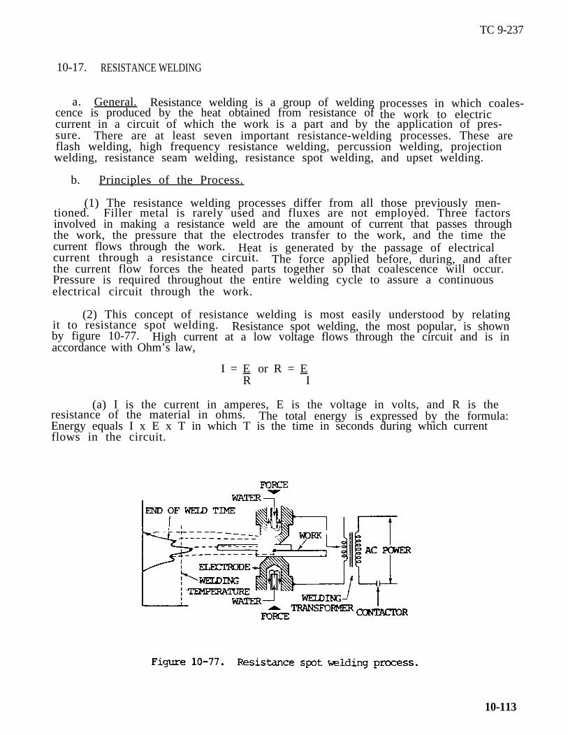
TC 9-237
10-17. RESISTANCE WELDING
a. General. Resistance welding is a group of weldingcence is produced by the heat obtained from resistance of
processes in which coales-the work to electric
current in a circuit of which the work is a part and by the application of pres-sure. There are at least seven important resistance-welding processes. These areflash welding, high frequency resistance welding, percussion welding, projectionwelding, resistance seam welding, resistance spot welding, and upset welding.
b. Principles of the Process.
(1) The resistance welding processes differ from all those previously men-tioned. Filler metal is rarely used and fluxes are not employed. Three factorsinvolved in making a resistance weld are the amount of current that passes throughthe work, the pressure that the electrodes transfer to the work, and the time thecurrent flows through the work. Heat is generated by the passage of electricalcurrent through a resistance circuit. The force applied before, during, and afterthe current flow forces the heated parts together so that coalescence will occur.Pressure is required throughout the entire welding cycle to assure a continuouselectrical circuit through the work.
(2) This concept of resistance welding is most easily understood by relatingit to resistance spot welding. Resistance spot welding, the most popular, is shownby figure 10-77. High current at a low voltage flows through the circuit and is inaccordance with Ohm’s law,
I = E or R = E R I
(a) I is the current in amperes, E is the voltage in volts, and R is theresistance of the material in ohms. The total energy is expressed by the formula:Energy equals I x E x T in which T is the time in seconds during which currentflows in the circuit.
10-113

TC 9-237
10-17. RESISTANCE WELDING (cont)
(b) Combining these two equations gives H (heat energy) = 12 x R x T. Forpractical reasons a factor which relates to heat losses should be included; there-fore, the actual resistance welding formula is
H(heat energy) = I2 x R x T x K
(c) In this formula, I = current squared in amperes, R is the resistance ofthe work in ohms, T is the time of current flow in seconds, and K represents theheat losses through radiation and conduction.
(3) Welding heat is proportional to the square of the welding current. Ifthe current is doubled, the heat generated is quadrupled. Welding heat is propor-tional to the total time of current flow, thus, if current is doubled, the time canbe reduced considerably. The welding heat generated is directly proportional tothe resistance and is related to the material being welded and the pressure ap-plied. The heat losses should be held to a minimum. It is an advantage to shortenwelding tire. Mechanical pressure which forces the parts together helps refine thegrain structure of the weld.
(4) Heat is also generated at the contact between the welding electrodes andthe work. This amount of heat generated is lower since the resistance between highconductivity electrode material and the normally employed mild steel is less thanthat between two pieces of mild steel. In most applications, the electrodes arewater cooled to minimize the heat generated between the electrode and the work.
(5) Resistance welds are made very quickly; however, each process has its owntime cycle.
(6) Resistance welding operations are automatic. The pressure is applied bymechanical, hydraulic, or pneumatic systems. Motion, when it is involved, is ap-plied mechanically. Current control is completely automatic once the welding opera-tor initiates the weld. Resistance welding equipment utilizes programmers forcontrolling current, time cycles, pressure, and movement. Welding programs forresistance welding can become quite complex. In view of this, quality welds do notdepend on welding operator skill but more on the proper set up and adjustment ofthe equipment and adherence to weld schedules.
(7) Resistance welding is used primarily in the mass production industrieswhere long production runs and consistent conditions can be maintained. Welding isperformed with operators who normally load and unload the welding machine and oper-ate the switch for initiating the weld operation. The automotive industry is themajor user of the resistance welding processes, followed by the appliance indus-try. Resistance welding is used by many industries manufacturing a variety ofproducts made of thinner guage metals. Resistance welding is also used in thesteel industry for manufacturing pipe, tubing and smaller structural sections.Resistance welding has the advantage of producing a high volume of work at highspeeds and does not require filler materials. Resistance welds are reproducibleand high-quality welds are normal.
(8) The position of making resistance welds is not a factor, particularly inthe welding of thinner material.
10-114
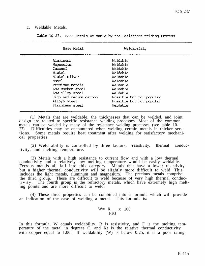
TC 9-237
c. Weldable Metals.
(1) Metals that are weldable, the thicknesses that can be welded, and jointdesign are related to specific resistance welding processes. Most of the commonmetals can be welded by many of the resistance welding processes (see table 10-27) . Difficulties may be encountered when welding certain metals in thicker sec-tions. Some metals require heat treatment after welding for satisfactory mechani-cal properties.
(2) Weld ability is controlled by three factors: resistivity, thermal conduc-tivity, and melting temperature.
(3) Metals with a high resistance to current flow and with a low thermalconductivity and a relatively low melting temperature would be easily weldable.Ferrous metals all fall into this category. Metals that have a lower resistivitybut a higher thermal conductivity will be slightly more difficult to weld. Thisincludes the light metals, aluminum and magnesium. The precious metals comprisethe third group. These are difficult to weld because of very high thermal conduc-t iv i ty . The fourth group is the refractory metals, which have extremely high melt-ing points and are more difficult to weld.
(4) These three properties can be combined into a formula which will providean indication of the ease of welding a metal. This formula is:
W= R x 100FKt
In this formula, W equals weldability, R is resistivity, and F is the melting tem-perature of the metal in degrees C, and Kt is the relative thermal conductivitywith copper equal to 1.00. If weldability (W) is below 0.25, it is a poor rating.
10-115

TC 9-237
10-17. RESISTANCE WELDING (cont)
If W is between 0.25 and 0.75, weldability becomes fair. Between 0.75 and 2.0,weldability is good. Above 2.0 weldability is excellent. In this formula, mildsteel would have a weldability rating of over 10. Aluminum has a weldability fac-tor of from 1 to 2 depending on the alloy and these are considered having a goodweldability rating. Copper and certain brasses have a low weldability factor andare known to be very difficult to weld.
10-18.
a.
FLASH WELDING (FW)
General.
(1) Flash welding is a resistance welding process which produces coalescencesimultaneously over the entire area of abutting surfaces by the heat obtained fromresistance to electric current between the two surfaces, and by the application ofpressure after heating is substantially completed. Flashing and upsetting areaccompanied by expulsion of metal from the joint. This is shown by figure 10-78.During the welding operation, there is an intense flashing arc and heating of themetal on the surfaces abutting each other. After a predetermined time, the twopieces are forced together and joining occurs at the interface. Current flow ispossible because of the light contact between the two parts being flash welded.Heat is generated by the flashing and is localized in the area between the twoparts. The surfaces are brought to the melting point and expelled through theabutting area. As soon as this material is flashed away, another small arc isformed which continues until the entire abutting surfaces are at the melting temper-rature. Pressure is then applied. The arcs are extinguished and upsetting occurs.
10-116

TC 9-237
(2) Flash welding can be used on most metals. No special preparation isrequired except that heavy scale, rust, and grease must be removed. The jointsmust be cut square to provide an even flash across the entire surface. The materi-al to be welded is clamped in the jaws of the flash welding machine with a highclamping pressure. The upset pressure for steel exceeds 10,000 psi (68, 950 kPa).For high-strength materials, these pressures may be doubled. For tubing or hollowmembers, the pressures are reduced. As the weld area is more compact, upset pres-sures are increased. If insufficient upset pressure is used, a porous low strengthweld will result. Excess upset pressure will result in expelling too much weldmetal and upsetting cold metal. The weld may not be uniform across the entirecross section, and fatigue and impact strength will be reduced. The speed of up-set, or the time between the end of flashing period and the end of the upset period,should be extremely short to minimize oxidation of the molten surfaces. In theflash welding operation, a certain amount of material is flashed or burned away.The distance between the jaws after welding compared to the distance before weldingis known as the burnoff. It can be from 1/8 in. (3.2 mm) for thin material up toseveral inches for heavy material. Welding currents are high and are related tothe following: 50 kva per square in. cross section at 8 seconds. It is desirableto use the lowest flashing voltage at a desired flashing speed. The lowest voltageis normally 2 to 5 volts per square in. of cross section of the weld.
(3) The upsetting force is usually accomplished by means of mechanical camaction. The design of the cam is related to the size of the parts being welded.Flash welding is completely automatic and is an excellent process for mass-producedparts . It requires a machine of large capacity designed specifically for the partsto be welded. Flash welds produce a fin around the periphery of the weld which isnormally removed.
10-19. FRICTION WELDING (FRW)
a. General.
(1) Friction welding is a solid state welding process which produces coales-cence of materials by the heat obtained from mechanically-induced sliding motionbetween rubbing surfaces. The work parts are held together under pressure. Thisprocess usually involves the rotating of one part against another to generate fric-tional heat at the junction. When a suitable high temperature has keen reached,rotational notion ceases. Additional pressure is applied and coalescence occurs.
(2) There are two variations of the friction welding process. They are de-scribed below.
(a) In the original process, one part is held stationary and the other partis rotated by a motor which maintains an essentially constant rotational speed.The two parts are brought in contact under pressure for a specified period of timewith a specific pressure. Rotating power is disengaged from the rotating piece andthe pressure is increased. When the rotating piece stops, the weld is completed.This process can be accurately controlled when speed, pressure, and time are close-ly regulated.
10-117

TC 9-237
10-19. FRICTION WELDING (FRW) (cont)
(b) The other variation is inertia welding. A flywheel is revolved by amotor until a preset speed is reached. It, in turn, rotates one of the pieces tobe welded. The motor is disengaged from the flywheel and the other part to bewelded is brought in contact under pressure with the rotating piece. During thepredetermined time during which the rotational speed of the part is reduced, theflywheel is brought to an immediate stop. Additional pressure is provided to com-plete the weld.
(c) Both methods utilize frictional heat and produce welds of similar quali-ty. Slightly better control is claimed with the original process. The two methodsare similar, offer the same welding advantages, and are shown by figure 10-79.
10-118

TC 9-237
b. Advantages.
(1) Friction welding can produce high quality welds in a short cycle time.
(2) No filler metal is required and flux is not used.
(3) The process is capable of welding most of the common metals. It can alsobe used to join many combinations of dissimilar metals. Friction welding requiresrelatively expensive apparatus similar to a machine tool.
c. Process Principles.
(1) There are three important factors involved in making a friction weld:
(a) The rotational speed which is related to the material to be welded andthe diameter of the weld at the interface.
(b) The pressure between the two parts to be welded. Pressure changesduring the weld sequence. At the start, pressure is very low, but is increased tocreate the frictional heat. When the rotation is stopped, pressure is rapidlyincreased so forging takes place immediately before or after rotation is stopped.
(c) The welding time is related to the shape and the type of metal and thesurface area. It is normally a matter of a few seconds. The actual operation ofthe machine is automatic. It is controlled by a sequence controller, which can beset according to the weld schedule established for the parts to be joined.
(2) Nomally for friction welding, one of the parts to be welded is round incross section. This is not an absolute necessity. Visual inspection of weld quali-ty can be based on the flash, which occurs around the outside perimeter of theweld. This flash will usually extend beyond the outside diameter of the parts andwill curl around back toward the part but will have the joint extending beyond theoutside diameter of the part.
(a) If the flash stickscates that the welding time waswas too high. These joints may
(b) If the flash curls toothat the the was too long and the
(c) Between these extremesly remved after welding.
out relatively straight from the joint, it indi-too short, the pressure was too low, or the speedcrack.
far back on the outside diameter, it indicatespressure was too high.
is the correct flash shape. The flash is normal-
10-119

TC 9-237
10-20. ELECTRON BEAM WELDING
a. General.
(1) Electron beam welding (EBW) is a welding process which produces coales-cence of metals with heat from a concentrated beam of high velocity electrons strik-ing the surfaces to be joined. Heat is generated in the workpiece as it is bomard-ed by a dense stream of high-velocity electrons. Virtually all of the kineticenergy, or the energy of motion, of the electrons is transformed into heat uponimpact .
(2) Two basic designs of this process are: the low-voltage electron beamsystem, which uses accelerating voltages in 30,000-volt (30 kv) to 60,000-volt (60kv) range, and the high voltage system with accelerating voltages in the100,000-volt (100 kv) range. The higher voltage system emits more X-rays than thelower voltage system. In an X-ray tube, the beam of electrons is focused on a tar-get of either tungsten or molybdenum which gives off X-rays. The target becomesextremely hot and must be water cooled. In welding, the target is the base metalwhich absorbs the heat to bring it to the molten stage. In electron beam welding,X-rays may be produced if the electrical potential is sufficiently high. In bothsystems, the electron gun and the workpiece are housed in a vacuum chamber. Figure10-80 shows the principles of the electron beam welding process
b. Equipment.
(1) There are three basic components in an electron beam welding machine.These are the electron beam gun, the power supply with controls, and a vacuum workchamber with work-handling equipment.
10-120

TC 9-237
(2) The electron beam gun emits electrons, accelerates the beam of electrons,and focuses it on the workpiece. The electron beam gun is similar to that used ina television picture tube. The electrons are emitted by a heated cathode or fila-ment and accelerated by an anode which is a positively-charged plate with a holethrough which the electron beam passes. Magnetic focusing coils located beyond theanode focus and deflect the electron beam.
(3) In the electron beam welding machine, the electron beam is focused on theworkpiece at the point of welding. The power supply furnishes both the filamentcurrent and the accelerating voltage. Both can be changed to provide differentpower input to the weld.
(4) The vacuum work chamber must be an absolutely airtight container. It isevacuated by means of mechanical pumps and diffusion pumps to reduce the pressureto a high vacuum. Work-handling equipnent is required to move the workpiece underthe electron beam and to manipulate it as required to make the weld. The travelmechanisms must be designed for vacuum installations since normal greases, lubri-cants, and certain insulating varnishes in electric rotors may volatilize in avacuum. Heretically sealed motors and sealed gearboxes must be used. In somecases, the rotor and gearboxes are located outside the vacuum chamber with shaftsoperating through sealed bearings.
c. Advantages. One of the major advantages of electron beam welding is itstremendous penetration. This occurs when the highly accelerated electron hits thebase metal. It will penetrate slightly below the surface and at that point releasethe bulk of its kinetic energy which turns to heat energy. The addition of theheat brings about a substantial temperature increase at the point of impact. Thesuccession of electrons striking the same place causes melting and then evaporationof the base metal. This creates metal vapors but the electron beam travels throughthe vapor much easier than solid metal. This causes the beam to penetrate deeperinto the base metal. The width of the penetration pattern is extremely narrow.The depth-to-width can exceed a ratio of 20 to 1. As the power density is in–creased, penetration is increased. Since the electron beam has tremendous penetrat-ing characteristics, with the lower heat input, the heat affected zone is muchsmaller than that of any arc welding process. In addition, because of the almostparallel sides of the weld nugget, distortion is very greatly minimized. The cool-ing rate is much higher and for many metals this is advantageous; however, for highcarbon steel this is a disadvantage and cracking may occur.
d. Process Principles.
(1) Recent advances in equipment allow the work chamber to operate at a medi-um vacuum or pressure. In this system, the vacuum in the work chamber is not ashigh. It is sometimes called a “soft” vacuum This vacuum range allowed the samecontamination that would be obtained in atmosphere of 99.995 percent argon. Mechan-ical pumps can produce vacuums to the medium pressure level.
(2) Electron beam welding was initially done in a vacuum because the electronbeam is easily deflected by air. The electrons in the beam collide with the mole-cules of the air and lose velocity and direction so that welding can not be per-formed .
10-121

TC 9-237
10-20. ELECTRON BEAM WELDING (cont)
(3) In a high vacuum system, the electron beam can be located as far as 30.0in. (762.0 mm) away from the workpiece. In the medium vacuum, the working distanceis reduced to 12.0 in. (304.8 mm). The thickness that can be welded in a highvacuum is up to 6.0 in. (152.4 mm) thick while in the medium vacuum the thicknessthat can be welded is reduced to 2.0 in. (50.8 mm). This is based on the sameelectron gun and power in both cases. With the medium vacuum, pump down time isreduced. The vacuum can be obtained by using mechanical pumps only. In the mediumvacuum mode, the electron gun is in its own separate chamber separate from thework chamber by a small orifice through which the electron beam travels. A diffu-sion vacuum pump is run continuously, connected to the chamber containing the elec-tron gun, so that it will operate efficiently.
(4) The most recent development is the nonvacuum electron beam welding sys-tem. In this system, the work area is maintained at atmospheric pressure duringwelding. The electron beam gun is housed in a high vacuum chamber. There areseveral intermediate chambers between the gun and the atmospheric work area. Eachof these intermediate stages is reduced in pressure by means of vacuum pumps. Theelectron beam passes from one chamber to another through a small orifice largeenough for the electron beam but too small for a large volume of air. By means ofthese differential pressure chambers, a high vacuum is maintained in the electronbeam gun chamber. The nonvacuum system can thus be used for the largest weldments,however the workpiece must be positional with 1-1/2 in. (38 mm) of the beam exitnozzle. The maximum thickness that can be welded currently is approximately 2 in.(51 mm). The nonvacuum system utilizes the high-voltage power supply.
(5) The heat input of electron beam welding is controlled by four variables:
(a) Number of electrons per second hitting the workpiece or beam current.
(b) Electron speed at the moment of impact, the accelerating potential.
(c) Diameter of the beam at or within the workpiece, the beam spot size.
(d) Speed of travel or the welding speed.
(6) The first two variables in (5), beam current and accelerating potential,are used in establishing welding parameters. The third factor, the beam spot size,is related to the focus of the beam, and the fourth factor is also part of theprocedure. The electron beam current ranges from 250 to 1000 milliamperes, thebeam currents can be as low as 25 milliamperes. The accelerating voltage is withinthe two ranges mentioned previously. Travel speeds can be extremely high and re-late to the thickness of the base metal. The other parameter that must be con-trolled is the gun-to-work distance.
(7) The beam spot size can be varied by the location of the fecal point withrespect to the surface of the part. Penetration can be increased by placing thefecal point below the surface of the base metal. As it is increased in depth belowthe surface, deeper penetration will result. When the beam is focused at the sur-face, there will be more reinforcement on the surface. When the beam is focusedabove the surface, there will be excessive reinforcement and the width of the weldwill be greater.
10-122

TC 9-237
(8) Penetration is also dependent on the beam current. As beam current isincreased, penetration is increased. The other variable, travel speed, also af-fects penetration. As travel speed is increased, penetration is reduced.
(9) The heat input produced by electron beam welds is relatively small com-pared to the arc welding processes. The power in an electron beam weld comparedwith a gas metal arc weld would be in the same relative amount. The gas metal arcweld would require higher power to produce the same depth of penetration. Theenergy in joules per inch for the electron beam weld may be only 1/10 as great asthe gas metal arc weld. The electron beam weld is equivalent to the SMAW weld withless power because of the penetration obtainable by electron beam welding. Thepower density is in the range of 100 to 10,000 kw/in2.
(10) The weld joint details for electron beam welding must be selected withcare. In high vacuum chamber welding, special techniques must be used to properlyalign the electron beam with the joint. Welds are extremely narrow. Preparationfor welding must be extremely accurate. The width of a weld in 1/2 in. (12.7 mm)thick stainless steel would only be 0.04 in. (1.00 mm). Small misalignment wouldcause the electron beam to completely miss the weld joint. Special optical systemsare used which allow the operator to align the work with the electron beam. Theelectron beam is not visible in the vacuum. Welding joint details normally usedwith gas tungsten arc welding can be used with electron beam welding. The depth towidth ratio allows for special lap type joints. Where joint fitup is not precise,ordinary lap joints are used and the weld is an arc seam type of weld. Normally,filler metal is not used in electron beam welding; however, when welding mild steelhighly deoxidized filler metal is sometimes used. This helps deoxidize the moltenmetal and produce dense welds.
(11 ) In the case of the medium vacuum system, much larger work chambers can beused. Newer systems are available where the chamber is sealed around the part tobe welded. In this case, it has to be designed specifically for the job at hand.The latest uses a sliding seal and a movable electron beam gun. In other versionsof the medium vacuum system, parts can be brought into and taken out of the vacuumwork chamber by means of interlocks so that the process can be made more or lesscontinuous. The automotive industry is using this system for welding gear clustersand other small assemblies of completely machined parts. This can be done sincethe distortion is minimal.
(12) The non-vacuum system is finding acceptance for other applications. Oneof the most productive applications is the welding of automotive catalytic convert-ers around the entire periphery of the converter.
(13) The electron beam process is becoming increasingly popular where the costof equipment can be justified over the production of many parts. It is also usedto a very great degree in the automatic energy industry for remote welding and forwelding the refractory metals. Electron beam welding is not a cure-all; there arestill the possibilities of defects of welds in this process as with any other. Themajor problem is the welding of plain carbon steel which tends to become porouswhen welded in a vacuum. The melting of the metal releases gases originally in themetal and results in a porous weld. If deoxidizers cannot be used, the process isnot suitable.
10-123

e. Weldable Metals.
TC 9-237
10-20. ELECTRON BEAM WELDING (cont)
Almost all metals can be welded with the electron beam welding process. The metalsthat are most often welded are the super alloys, the refractory metals, the reac-tive metals, and the stainless steels. Many combinations of dissimilar metals canalso be welded.
10-21. LASER BEAM WELDING (LBW)
a. General.
(1) Laser beam welding (LBW) is a welding process which produces coalescenceof materials with the heat obtained from the application of a concentrate coherentlight beam impinging upon the surfaces to be joined.
(2) The focused laser beam has the highest energy concentration of any knownsource of energy. The laser beam is a source of electromagnetic energy or lightthat can be pro jetted without diverging and can be concentrated to a precise spot.The beam is coherent and of a single frequency.
(3) Gases can emit coherent radiation when contained in an optical resonantcavity. Gas lasers can be operated continuously but originally only at low levelsof power. Later developments allowed the gases in the laser to be cooled so thatit could be operated continuously at higher power outputs. The gas lasers arepumped by high radio frequency generators which raise the gas atoms to sufficientlyhigh energy level to cause lasing. Currently, 2000-watt carbon dioxide laser sys-tems are in use. Higher powered systems are also being used for experimental anddevelopmental work. A 6-kw laser is being used for automotive welding applicationsand a 10-kw laser has been built for research purposes. There are other types oflasers; however, the continuous carbon dioxide laser now available with 100 wattsto 10 kw of power seems the most promising for metalworking applications.
(4) The coherent light emitted by the laser can be focused and reflected inthe same way as a light beam. The focused spot size is controlled by a choice oflenses and the distance from it to the base metal. The spot can be made as smallas 0.003 in. (O. 076 mm) to large areas 10 times as big. A sharply focused spot isused for welding and for cutting. The large spot is used for heat treating.
(S) The laser offers a source of concentrated energy for welding; however,there are only a few lasers in actual production use today. The high-powered laseris extremely expensive. Laser welding technology is still in its infancy so therewill be improvements and the cost of equipment will be reduced. Recent use offiber optic techniques to carry the laser beam to the point of welding may greatlyexpand the use of lasers in metal-working.
b. Welding with Lasers.
(1) The laser can be compared to solar light beam for welding. It can beused in air. The laser beam can be focused and directed by special optical lensesand mirrors. It can operate at considerable distance from the workpiece.
10-124

TC 9-237
(2) When using the laser beam for welding, the electromagnetic radiationimpinges on the surface of the base metal with such a concentration of energy thatthe temperature of the surface is melted vapor and melts the metal below. One ofthe original questions concerning the use of the laser was the possibility of re-flectivity of the metal so that the beam would be reflected rather than heat thebase metal. It was found, however, that once the metal is raised to its meltingtemperature, the surface conditions have little or no effect.
(3) The distance from the optical cavity to the base metal has little effecton the laser. The laser beam is coherent and it diverges very little. It can befocused to the proper spot size at the work with the same amount of energy avail-able, whether it is close or far away.
(4) With laser welding, the molten meta1 takes on a radial configurationsimilar to convectional arc welding. However, when the power density rises above acertain threshold level, keyholing occurs, as with plasma arc welding. Keyholingprovides for extremely deep penetration. This provides for a high depth-to-widthratio. Keyholing also minimizes the problem of beam reflection from the shinymolten metal surface since the keyhole behaves like a black body and absorbs themajority of the energy. In some applications, inert gas is used to shield themolten metal from the atmosphere. The metal vapor that occurs may cause a break–down of the shielding gas and creates a plasma in the region of high-beam intensityjust above the metal surface. The plasma absorbs energy from the laser beam andcan actually block the beam and reduce melting. Use of an inert gas jet directedalong the metal surface eliminates the plasma buildup and shields the surface fromthe atmosphere.
(5) The welding characteristics of the laser and of the electron beam aresimilar. The concentration of energy y both beams is similar with the laser hav-ing a power density in the order of 106 watts per square centimeter. The powerdensity of the electron beam is only slightly greater. This is compared to a cur-rent density of only 104 watts per square centimeter for arc welding.
(6) Laser beam welding has a tremendous temperature differential between themolten metal and the base metal immediately adjacent to the weld. Heating andcooling rates are much higher in laser beam welding than in arc welding, and theheat-affected zones are much smaller. Rapid cooling rates can create problems suchas cracking in high carbon steels.
(7) Experimental work with the laser beam welding process indicates that thenormal factors control the weld. Maximum penetration occurs when the beam is fo-cused slightly below the surface. Penetration is less when the beam is focused onthe surface or deep within the surface. As power is increased the depth of penetra-tion is increased.
c. Weldable Metals. The laser beam has been used to weld carbon steels, highstrength 1ow alloy steels, aluminum, stainless steel, and titanium. Laser weldsmade in these materials are similar in quality to welds made in the same materialsby electron beam process. Experimental work using filler metal is being used toweld metals that tend to show porosity when welded with either EB or LB welding.Materials 1/2 in. (12.7 mm) thick are being welded at a speed of 10.0 in. (254.0mm) per minute.
10-125(10-126 blank)
