chapter 1 – your new orion orion –the next step in ten …
TRANSCRIPT

565 manual September 2003Part #74279Printed in USA
1
TABLE OF CONTENTS
TABLE OF CONTENTS 1
Chapter 1 – YOUR NEW ORIONORION –THE NEXT STEP IN TEN-TEC INNOVATION 4UNPACKING YOUR NEW ORION 4CONNECTING A POWER SUPPLY 4A WORD ABOUT GROUNDING 5HOW IS ORION DIFFERENT FROM OTHER HIGH-PERFORMANCEHF TRANSCEIVERS? 5
Chapter 2 – ORION FRONT AND REAR PANEL CONTROLS AND THEIR FUNCTIONSANALOG METER 7(1) POWER 7(2 – 7) ANTENNA ASSIGNMENTS 7(8 – 13) VFO ASSIGNMENTS 8(14) MIC 9(15) PHONES 10(16) CW 11(17) PWR 12(18) MON 12(19) SP 13(20) SEND FUNCTIONS 13(21) USER 1 AND USER 2 14(22) RECALL 14(23) NB 14(24) NR 15(25) NOTCH 15(26) AN 15(27) MODE 15(28) PREAMP 16(29) RF GAIN 16(30) SPOT 16(31) STEP 16(32) SWEEP 16(33) AGC 16(34) ATTN 17(35) MENUS 17(36) AUDIO 17(37) VOX 19(38) S-TONE 19(39) MIC 19(40) TUNE 19ALC 20(41) PBT/BW ENCODER 21(42) MULTI ENCODER 21(43) HI CUT – LO CUT 21(44) MAIN AF ENCODER 22(45) SUB AF ENCODER 22(46) RIT/XIT ENCODER 22(47) MAIN TUNING KNOB “A” 22(48) RIT 22(49) VFO A>M 22(50) and (51) LCK 23(52) VFO B>M 23

565 manual September 2003Part #74279Printed in USA
2
(53) XIT 23(54) MAIN TUNING KNOB “B” 23(55) MAIN RX 23(56) SUB RX 23(57) FREQUENCY ENTRY AND BAND CHANGE BUTTONS 23(58) VFO A ENTER 24(59) VFO B ENTER 24(60) A>B, B>A, A/B 24(61) ANT 1 25(62) ANT 2 25(63) DC IN 25(64) FUSE 25 A 25(65) GND 25(66) AMP KEY 1 26(67) TX OUT 1 / TX EN 1 26(68) AMP KEY 2 26(69) TX OUT 2 / TX EN 2 26(70) +13.8 VDC 27(71) AUX RX 27(72) XVRT KEY 27(73) XVRT RF 27(74) LINE OUT 27(75) SPARE 27(76) BAND DATA 1 27(77) BAND DATA 2 27(78) EXT SPKR 28(79) KEY 28(80) AUX I/O 28(81) REMOTE 29(82) SERIAL DATA 29
Chapter 3 – MENU SYSTEM
(TX) TX MENU 30(CW) CW MENU 31(VOX) VOX MENU 32(RX) RX MENU 32(OTHER) OTHER MENU 34(SSB) SSB MENU 35(FILTR) FILTER MENU 35
Chapter 4 – OPERATION AND ACCESSORY CONNECTION EXAMPLES
BASIC TRANSCEIVE OPERATION 37OPERATING SPLIT FREQUENCY 37OPERATING THE AUTOMATIC ANTENNA TUNER (IF INSTALLED) 38CONNECTING AN EXTERNAL LINEAR AMPLIFIER 38TUNING UP AN EXTERNAL LINEAR AMPLIFIER 39FACTORS THAT AFFECT THE SOUND OF SSB TRANSMITAND THEIR ADJUSTMENT 39SETTING UP ORION FOR AM TRANSMIT 42FSK OPERATION 42TRANSVERTER HOOKUPS 42DIVERSITY RECEPTION 43WEAK SIGNAL DX RECEPTION AND CONTEST OPERATIONAND THE ORION 44

565 manual September 2003Part #74279Printed in USA
3
EXTERNAL CW OUTPUT PLUS CW KEYER OPERATIONFROM PADDLES 47DRAG ADJUSTMENT FOR MAIN TUNING KNOBS “A” AND “B” 47MASTER RESET 47UPGRADING ORION OVER THE INTERNET 48TROUBLESHOOTING 48
Chapter 5 – SPECIFICATIONS AND TECHNICAL DESCRIPTIONSPECIFICATIONS 50HARDWARE INFORMATION 54SUBASSEMBLY LOCATION 54SIGNAL PATH – MAIN RECEIVER 54SIGNAL PATH – SUBRECEIVER 55SIGNAL PATH – TRANSMITTER 55

565 manual September 2003Part #74279Printed in USA
4
Chapter 1 – YOUR NEW ORION
ORION –THE NEXT STEP IN TEN-TECINNOVATION
The Ten-Tec ORION represents the mostinnovative HF transceiver ever created foramateur radio use.
Our aim in designing and producing thisradio was to meet the demands ofincreasingly intense competition in DX andcontesting, while adding many non-performance related features that the activeham can also appreciate. The features andperformance ORION brings to ham radio willenhance HF radio contacts of all sorts, whileopening new possibilities for amateur radiooperation. ORION offers world-classreception and transmission of CW, SSB,digital modes, FM, and AM on all 10 HFamateur bands, plus excellent generalcoverage reception via the second (sub)receiver from 100 kHz to 30 MHz.
UNPACKING YOUR NEW ORION
Examine ORION for signs of shippingdamage. Should any damage be apparent,notify the delivering carrier immediately,stating the full extent of the damage.
Retain all damaged cartons. Liability forshipping damage rests with the carrier. Werecommend that you keep the carton andfillers in the event that storage, moving, orshipment becomes necessary.
The following hardware and accessoriescome standard with your ORION. Makesure that you have not overlooked anything.
Qty Part # Description
1 #27074 Mini-ATC BladeFuse, 25 Amp.
1 #35003 Phono Plug1 #35057 4-pin Microphone
Connector1 #35163 1/8 in. Stereo Plug1 #35165 2-pin Power
Connector Shell2 #41020 Female Power Pins
6 ft #46159 Wire, Red & Blk,#12
1 #35013 Phone Plug, 3-circuit
1 #35331 Shell, Band DataPlug
15 #41068 Band Data PlugPins
1 #38040 .050 Hex Wrench1 #38088 .062 Hex Wrench1 38313 T10 Torx Wrench
1 #46176 Accessory Cable.5-pin DIN to PhonoF.
1 #74020 Warranty Card1 #74279 User’s Manual1 #86095 DC Power Cord
Figure 1-1 ORION Packing Kit
CONNECTING A POWER SUPPLY
The ORION transceiver requires a source ofwell-filtered and regulated DC voltage. Thesupply voltage can range from +12.8 to+15.0 Vdc but +13.8 Vdc is the optimumvalue. The voltage source must be capableof supplying 22 amperes continuous duty.
We recommend using the included DCpower cable (P/N 86095). We have alsoincluded spare connector pins (P/N 41020)and a spare 2 pin power connector shell(P/N 35165) for building your own cable.The power supply plug will attach in onlyone direction to the polarized two-pin DCconnector on ORION’s rear panel. Use noless than #14 gauge (#12 recommended)stranded wires for three-foot longconnections to accommodate the requiredcurrent demand during transmit. Useheavier gauge wire for longer power supplyleads.

565 manual September 2003Part #74279Printed in USA
5
NOTE: always enable the power source firstand then the transceiver. If a generator oralternator supports the dc source, alwaysturn off the transceiver before starting orshutting off the dc source equipment. Theserecharging devices often generate largevoltage spikes that can damage thetransceiver.
A WORD ABOUT GROUNDING
A good ground system is essential foroptimum operation of any HF transmitter.The best solution is to connect all the stationequipment chassis together using a heavygauge of flat ground braid. Use a shortlength of braid to connect to a ground rod. Ifyou are not using a linear amplifier, a lessideal ground may suffice. A groundconnection to a copper cold water pipe wasoften suitable, but that is now a violation ofthe National Electrical Code. Be aware thatmany modern water connections use plasticpipe, and are not suitable groundconnections.
Antenna type and its proximity to the stationare also factors in choosing groundmethods. With good resonant antennaslocated away from the station, the ACground in your house wiring might beadequate.
HOW IS ORION DIFFERENT FROMOTHER HIGH-PERFORMANCE HFTRANSCEIVERS?
ORION is different from HF transceivers thathave come before it. The use of mode-appropriate selectable crystal roofing filtersat the first I-F stage plus DSP bandwidthfiltering at the third I-F stage has never beenutilized in an amateur HF transceiverpreviously.
The mode-appropriate roofing filters used inORION’s main receiver are the centerpieceof the radio’s performance. It is common forradio designers to be able to produce areceiver that exhibits in excess of 100 dB ofavailable dynamic range. What is notcommon is the ability to protect superiorreceiver design from being compromised byreal-life on-band factors (i.e. loud closebysignals).
Mode-appropriate roofing filters keepcloseby loud signals from having a negativeimpact on receiver performance. A typicalhigh performance HF transceiver isequipped with a 15 to 20 kHz wide roofingfilter at the first I-F stage. Any signal thatappears under the 15 to 20 kHz roofing filter,even if you do not hear it in your receiverpassband, has the potential to compromisereceiver performance. Loss of dynamicrange, third-order intercept or the receiverbreaking into non-linearity (distortion) arepossible results.
When dynamic range and third-orderintercept are compromised, the ability tocopy weak signals is also compromised.The typical 100 dB dynamic range highperformance HF radio, in the presence ofloud signals a few kHz above or a few kHzbelow the targeted receiver frequency, couldlose a significant amount of the available100 dB of range! Why? Because thoseloud signals under the 15 to 20 kHz wideroofing filter have had a negative impact onthe overall performance of the receiver.
If a mode-appropriate roofing filter issubstituted for the 15 or 20 kHz wide roofingfilter at the first I-F, the result is that closebyloud signals do not compromise dynamicrange or third-order intercept point. A 2.4kHz crystal filter will not allow loud signalsthat are 3 or 5 kHz away from the targetfrequency compromise the overallperformance of the receiver. This is whereevery other HF transceiver that has comebefore ORION is deficient. Imagine howmuch worse the receiver performance of acompetitor’s radio can be in the presence ofmany loud signals across the band (like in amajor contest).
ORION is equipped with a total of sevenavailable crystal roofing filter slots. Four ofthe seven crystal roofing filters are standard;three are optional. The standard roofingfilters included are 20 kHz, 6 kHz, 2.4 kHz,and 1 kHz. Optional filters are available at1.8 kHz (model 218), 500 Hz (model 217)and 250 Hz (model 219).
Note that the 20 kHz and 6 kHz roofingfilters are of limited utility for maintaining theoverall receiver performance level of a highend HF transceiver like ORION. They were

565 manual September 2003Part #74279Printed in USA
6
included only because AM and FM operationwould require them, and because someoperators with an interest in “hi-fidelity” SSBaudio will require receiver bandwidths higherthan the typical 2.4 kHz communicationsgrade roofing bandwidth would allow.Certainly the use of either a 20 kHz or 6 kHzwide roofing filter has the potential to allowoverall receiver performance (dynamicrange and third-order intercept point) to beseriously compromised by loud closebysignals. For serious receiver use, like weaksignal DXing and contesting, a much smallerroofing bandwidth than 20 or 6 kHz isnecessary. In ORION for SSB use, it can beas little as 1.8 kHz for roofing. For CW, itcan be as little as 250 Hz, depending on theinstallation of optional filters.
For some recommended real-worldexamples of how roofing filters affect overallreceiver performance, please look at recentARRL Product Reviews from QST magazinewhere dynamic range and third-orderintercept are measured at 20 kHz and 5 kHzsignal spacings. For our competitors’transceivers, the 5 kHz spacing numbers arealways significantly worse than the 20 kHzspacing numbers – this is because of thepresence of test signals under a 15 to 20kHz wide roofing filter vs. outside the filter.

565 manual September 2003Part #74279Printed in USA
7
Chapter 2 – ORION FRONT AND REARPANEL CONTROLS AND THEIRFUNCTIONS
Chapter 2 of the ORION manual covers thevarious controls and connectors on the frontand rear panels, with an explanation of theeach control and how it is used for operationof the radio.
ANALOG METER
An analog meter is provided at the upper lefthand side of the front of the transceiver. Inreceive, the meter shows S-units of signal
strength for the main receiver. In transmit,the meter shows approximate output power(+/- 5%). A separate bar graph S-meter forthe subreceiver is present on the radioscreen.
(1) POWER
This button turns the transceiver on and off.
(2 – 7) ANTENNA ASSIGNMENTS
The two columns of antenna selection keys(numbered 2 through 7 in the figure above)allow the assignment of up to three

565 manual September 2003Part #74279Printed in USA
8
connected antennas to each of the tworeceivers.
The most common arrangement would be tohave a single antenna connected to ANT 1used by either the main receiver only, or bythe main receiver and the subreceiver both.
Buttons 2, 4 and 6, as shown above, allowANT 1, ANT 2 or RX ANT to be connectedto the main receiver.
To connect an antenna attached to thetransceiver via the ANT 1 rear panel jack tothe main receiver, press button 2 shownabove. The amber LED embedded in thebutton will light, indicating the main receiveris now connected to ANT 1.
Pressing button 4 as shown above willconnect the main receiver to ANT 2.
When either of the ANT 1 or ANT 2 buttonsin the MAIN RX/TX column is lit, a receiveonly antenna can be substituted for thereceive side of ANT 1 or ANT 2 by pushingbutton 6 as shown in Figure 2-1.
Example: With button 2 or button 4 lit, pressbutton 6. The operator will note that thereare now two lighted buttons in this column,either of 2 or 4, plus 6. The radio willautomatically use either ANT 1 or ANT 2 fortransmit and RX ANT for receive in thisconfiguration.
Buttons 3, 5, and 7 control the assignmentof the subreceiver to each of the antennasconnected to the radio. The subreceiver caneither share the same antenna in use for themain receiver, or it can be split off to usedwith a separate antenna.
An antenna attached to ANT 1, ANT 2, orRX ANT can be used simultaneously withboth receivers or they can be split off toseparate receivers. One receiver cannot beused with two antennas at the same time.One antenna + one receiver, two antennas +two receivers, One antenna + two receiversare the available selections.
Additionally, button 2 is used for performinga master reset of the transceiver. See theMASTER RESET description in Chapter 4.
(8 – 13) VFO ASSIGNMENTS
While dual receive transceivers are commontoday, ORION allows an unprecedentedlevel of flexibility to the operator for mainand subreceiver control with the VFOassignment buttons. Receivers can beassigned to separate VFO’s (the mostcommon arrangement) or both receivers canbe assigned to a single VFO.
Important note: VFO’s are not receivers!The operator is permitted to assign eachVFO to either receiver and the transmitter.VFO’s can be adjusted even if NO receiveris selected for them.
The two large tuning knobs are for eachVFO. The large knob on the left closest tothe display screen is always VFO A, thelarge knob to the right is always VFO B.
Buttons 8 and 9 determine which VFO thetransmitter is assigned to. The TXfrequency also determines the output of theBAND DATA connectors on the ORION rearpanel (see description of 76 BAND DATA 1and 77 BAND DATA 2 elsewhere in thismanual).
Buttons 10 and 11 determine which VFO themain receiver is assigned to.
Buttons 12 and 13 determine which VFO thesub receiver is assigned to.
The assignments of the VFO’s are not onlyshown by the amber LED’s inside thebuttons, and are announced on the displayscreen. Shown in Figure 2-2 below is thedefault screen when powering up ORIONafter a master reset.

565 manual September 2003Part #74279Printed in USA
9
Figure 2-2 ORION Screen Display
Refer to Figure 2-2. Next to the 14.250.000frequency display for VFO A are the lettersTR. ‘T’ is for transmitter, ‘R’ is for mainreceiver, and ‘S’ is for sub receiver. As theoperator assigns the transmitter andreceivers using buttons 8 through 13, the TR and S indicators will move back and forthon the screen. If a transmitter or receiverhas no assignment, the annunciator will notbe shown.
The main receiver and the transmitter areamateur bands-only coverage. An attemptto assign them to a frequency outside theham bands will result in one of threemessages appearing on the screen:VFO-A OUTSIDE RX RANGE, VFO-BOUTSIDE RX RANGE or FREQUENCYNOT SUPPORTED depending on how theuser was attempting to put the main receiveron a non-amateur frequency.
Buttons 8 and 9 can be used to turn thetransmitter off by deselecting both buttons.Push 8 and 9 so neither light is lit. The Tindicator will not be present on the screen.
Buttons 12 and 13 can be used in a similarfashion to deselect the subreceiver, butthere will still be audio present through thesubreceiver audio chain on the last usedsubreceiver frequency when doing so – itwill not mute the subreceiver. Subreceiveraudio can be muted by turning the SUB AFencoder all the way counterclockwise or by
pressing it to mute. After no VFO isassigned to the subreceiver, the lastsubreceiver frequency will still be audible.
The main receiver cannot be disabled; it willalways be assigned to either VFO A or VFOB via buttons 10 and 11.
Receivers can be assigned to one VFO orthe other simultaneously. There areadvantages to doing so – see section thesection of Chapter 4 called DIVERSITYRECEPTION for information on diversityreceive capabilities using the two receivers,the VFO’s and multiple antennas.
(14) MIC
For connection of microphone. Any Ten-Tecmicrophone equipped with our 4 pinconnector may be used without modification.Most dynamic, ceramic, crystal, or electretmicrophones also work. When adaptinganother microphone, please refer to theconnector-wiring diagram. We include aspare 4-pin microphone connector (P/N35057) with the packing kit to allow rewiringof your current mic for use with ORION.The pinout for the 4 pin mic connector onthe front of the ORION is shown in Figure2-3. Wiring of the mic is shown below inFigure 2-4.
Front View of 565
PTT (3)
+9VDC (4) MIC (1)
GND (2)
Figure 2-3 Front view, mic connector

565 manual September 2003Part #74279Printed in USA
10
Figure 2-4 Microphone wiring for ORION
It is also important that the microphone bodyhave a common ground with the ORION.We recommend wiring microphone cablesas shown in Figure 2-5. Please note thatmic cables for the Ten-Tec 705 and 706microphones and the R9625 cable providedfor the Heil/Ten-Tec Studio One are alreadywired in this configuration. Many connectioncables, like those used for other Heilmicrophones, are not and have the potentialto introduce stray RF or distortion into SSBaudio.
Figure 2-5 Proper mic cable wiring.
(15) PHONES
DO NOT PLUG A MONO PHONE PLUG,(two-circuit) INTO ORION’s FRONTPANEL PHONES JACK UNLESSPROPERLY WIRED AS DESCRIBED !
The jack is optimally for stereo headphones.ORION uses left and right stereo outputsfrom two audio amps. A mono plug willshort-circuit one of the two audio channels,causing damage to the radio. Use a stereo(3-circuit) plug such as one that comespacked with your radio. Using stereoheadphones lets you take full advantage ofORION’s advanced features.
Audio from the front panel phones jack to astereo connector is left = tip, right = ring,ground = sleeve.
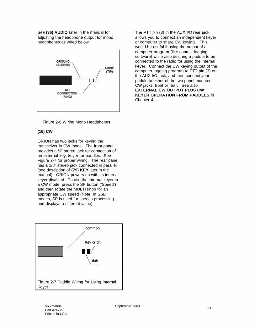
Mono headphones can be used withORION, provided they are wired correctlywith a stereo plug and the headphone audiosettings in the AUDIO menu are set to theappropriate values. You can use left sideaudio output to mono headphones by wiringthe headphones as shown in Figure 2-6.
565 manual September 2003Part #74279Printed in USA
11
See (36) AUDIO later in the manual foradjusting the headphone output for monoheadphones as wired below.
Figure 2-6 Wiring Mono Headphones
(16) CW
ORION has two jacks for keying thetransceiver in CW mode. The front panelprovides a ¼” stereo jack for connection ofan external key, keyer, or paddles. SeeFigure 2-7 for proper wiring. The rear panelhas a 1/8” stereo jack connected in parallel(see desciption of (79) KEY later in themanual). ORION powers up with its internalkeyer disabled. To use the internal keyer ina CW mode, press the SP button (‘Speed’)and then rotate the MULTI knob for anappropriate CW speed (Note: In SSBmodes, SP is used for speech processingand displays a different value).
common
Key or dit
dah
Figure 2-7 Paddle Wiring for Using InternalKeyer
The PTT pin (3) in the AUX I/O rear jackallows you to connect an independent keyeror computer to share CW keying. Thiswould be useful if using the output of acomputer program (like contest loggingsoftware) while also desiring a paddle to beconnected to the radio for using the internalkeyer. Connect the CW keying output of thecomputer logging program to PTT pin (3) onthe AUX I/O jack, and then connect yourpaddle to either of the two panel mountedCW jacks, front or rear. See alsoEXTERNAL CW OUTPUT PLUS CWKEYER OPERATION FROM PADDLES inChapter 4.

565 manual September 2003Part #74279Printed in USA
12
(17) PWR
This button is used for setting RF poweroutput on ORION. Press the PWR buttonthen turn the MULTI knob to adjust valuefrom 1 to 100. The value set from 1 to 100will roughly correspond to power output inwatts but this will vary a few wattsdepending on band and load impedance.
The PWR button also interacts with theTUNE button (40) for key down poweroutput for tuning an antenna tuner or linearamplifier. See the description of TUNE(button 40) later in this section.
If the low level drive transverter output hasbeen activated in the menu system, a lowlevel output RF output level of approximately+15 dBm will be sent through the XVRT RFjack. This output power value is adjustablefrom +5 to +15 dBm by using the PWR and
MULTI control when the transverter output isactivated in the menus.
(18) MON
ORION is equipped with a transmit audiomonitor to allow the operator to hear actualtransmitted audio. TX EQ, speechprocessing, TX bandwidth, LF rolloff all havean effect on the sound of the transmittedSSB signal, and to properly adjust thesecontrols for no distortion and desired sound,use the monitor.
Press the MON button. The volume ofmonitor level is expressed as a value from 1to 100% of available. Monitor is availablethrough either headphones or via thespeaker.
The MON function is also usable in FSKmode for monitoring of transmitted tones.

565 manual September 2003Part #74279Printed in USA
13
(19) SP
SP has two different functions depending onwhich mode the operator has selected. InSSB modes, the SP control is used forspeech processing. In LSB or USB mode,press the SP button to turn the speechprocessor on and off. When on, use theMULTI knob to adjust from a value of 1 to 9.Higher values represent more processing.Please note on the highest settings of 8 and9 that it is relatively easy to send the radiointo SSB transmit distortion depending onwhere the mic gain and other TX controlsare set! Use the monitor function to listen toyour transmitted audio.
The SP button is used for keyer speedcontrol in CW modes. Press the SP buttonwhen in LCW or UCW mode to activate theCW keyer. Speed control is 10 to 60 WPM.
(20) SEND FUNCTIONS
ORION is equipped with three CWmemories and three voice memories.ORION will retain three on each mode, for atotal of six. An asterisk (*) appears on theORION screen just to the right of eachbutton when a SEND memory has beenrecorded.
To record a message in a voice mode inSEND 1 or SEND 2: Press and hold theappropriate button for two seconds. Asubmenu titled DIGITAL VOICERECORDER CONTROL will appear at thebottom of the screen.
There are five options: EXIT, RECORD,PLAY, DELETE and SAVE. The fivebuttons below these options (numbers 22through 26) are used for these functions.To RECORD a message, press RECORD(button 23) and begin speaking into themicrophone. There are 4.54 seconds ofavailable recording time for each of theSEND 1 and SEND 2 voice memories.
When finished, you can check the recordingoff the air by pressing PLAY (button 24).To delete the recording, press DELETE(button 25).
To retain the memory after the transceiver ispowered off, press SAVE (button 26). A
message titled SAVING RECORDING willappear on the ORION screen for severalseconds during the save process.To exit the voice recorder control menu,press EXIT (button 22).
To play your message while on the air,momentarily push the appropriate SENDbutton and your recording will betransmitted.
To record a message in a voice mode inSEND 3: Follow the same instructions asfor SEND 1 or SEND 2. SEND 3’s messagecan be up to 28.1 seconds in length butcannot be retained in memory by using theSAVE button after recording. This memorywill erase after the transceiver is poweredoff.
To record a message in CW mode in SEND1, SEND 2, or SEND 3: Press and hold theappropriate button for two seconds. Asubmenu titled CW MEMORY KEYERCONTROL will appear at the bottom of thescreen.
There are four options: EXIT, RECORD,PLAY, and DELETE. The four buttonsbelow these options (numbers 22 through25) are used for these functions. Unlikevoice memories, all 3 CW memories areautomatically saved to memory whenrecorded and will retain after powering offthe transceiver.
To record a message in CW mode, pressRECORD (button 23) and begin sendingCW. The words EXIT, RECORD, PLAY,and DELETE will momentarily disappearand the word STOP will appear abovebutton 23. When you have completed yourrecording press button 23 to end (STOP).
To check your CW memory off the airwithout transmitting, press PLAY (button24). To delete the CW memory, pressDELETE (button 25). To exit the CWmemory keyer control menu, press EXIT(button 22).

565 manual September 2003Part #74279Printed in USA
14
(21) USER 1 AND USER 2
ORION is equipped with a total of five userprofiles. User profiles are like a “supermemory” – everything on the radio, allsettings, all menu selections, everything willbe saved to a user profile memory. Unliketraditional memories that save frequency,mode, bandwidth and maybe one or twoother parameters.
The USER 1 and USER 2 buttons allowsaving and recalling of user profile #1 anduser profile #2. User profiles #3, #4 anddefault (#5) are accessible by pressing theRECALL button (22).
To save a user profile in either USER 1 orUSER 2: Press and hold the desired buttonfor two seconds. Two messages will appearon the screen: STORING PARAMETERSET and then STORE COMPLETE.
To recall user profile #1 or #2, momentarilypress and release the USER 1 or USER 2buttons. A series of messages will appearon the screen while ORION recalls storedinformation: RECALLING PARAMETERSET, RESTORING USER MENU SET,RESTORING RADIO STATE, and RECALLCOMPLETE.
(22) RECALL
The RECALL button has two differentfunctions. One is to allow recall of savedmemories that have been entered using the200 available “traditional” memories. Theother function is to allow the operator toquickly recall the factory defaults for ORIONor to select one of the four programmableuser profiles.
To use RECALL to bring up either thefactory default settings or a stored userprofile, press and hold the RECALL buttonfor two seconds. A submenu will appear,titled FACTORY DEFAULTS and twooptions EXIT (using button 22) and RECALL(using button 24) will appear at the bottom ofthe screen. The operator can scroll amongthe factory defaults and the four user profilesby turning the MULTI knob located to theupper right of the screen. When turned, thesubmenu display will change to readPARAMETER BACKUP #1, #2…..etc. The
options of EXIT, STORE, and RECALL aregiven.
Factory defaults will return the radio to thestate as after doing a master reset.
Note that PARAMETER BACKUP #1 andPARAMETER BACKUP #2 are duplicates ofthe user profiles that can be saved andrecalled by using the USER 1 and USER 2buttons. #3 and #4 and factory defaults areonly accessible via this RECALL submenu.
RECALL is also used for recalling thetraditional memories saved using the VFOA>M and VFO B>M buttons. To access therecall of memories, momentarily press andrelease the RECALL button. A submenutitled MEMORY RECALL will appear.
Stored memories can be examined usingthe MULTI knob. Turn the MULTI knob tosee all stored memories with frequency andmode information.
Four options are shown under the memorylocations: EXIT, M>VFO A, M>VFO B, andDELETE. Each of these functions usesbuttons 22 through 25, directly under theoptions shown on the screen.
To recall a stored memory to VFO A, pressM>VFO A (button 23). To recall a storedmemory to VFO B, press M>VFO B (button24). To delete a stored memory, pressDELETE (button 25). To exit the memoryrecall submenu, press EXIT (button 22).
(23) NB
The ORION is equipped with a DSP noiseblanker that is independently adjustable foreach receiver.
To adjust the DSP noise blanker, press NB(button 23). A value of 1 through 9 willappear on the screen just above the NBbutton. Use the MULTI knob to adjust thenoise blanker value from 1 to 9. A highervalue indicates more aggressive noiseblanker action – please note that high noiseblanker settings on loud SSB signals canlead to intermodulation distortion of receivedsignals.

565 manual September 2003Part #74279Printed in USA
15
The DSP noise blanker is adjustableindependently for each receiver, dependingon which is selected for control by the MAINRX and SUB RX buttons located betweenthe two large main tuning knobs. Seedescription later in this chapter of (55) SUBRX and (56) MAIN RX for information onthese buttons and their functions.
Separate from the DSP NB, the mainreceiver only has a hardware noise blankeravailable. See the description of thehardware noise blanker in chapter 3 under(RX) RX MENU. This main receiverhardware noise blanker can be usedtogether with or separate from the DSP NB.
The hardware NB can be turned on and offfrom the front panel by pressing and holdingthe NB button for two seconds. It also canbe turned on or off through the menusystem. When the hardware noise blankeris activated on the main receiver, anannunicator marked :H will appear next tothe software noise blanker value on thescreen.
(24) NR
ORION is equipped with DSP noisereduction that is independently adjustablefor each receiver.
There are nine different settings, and eachof the nine are used to determine howaggressively (quickly) the NR adapts andidentifies what is signal and what is noise.
Once the noise reduction value has been setfor a given signal, no further adjustment ofthe noise reduction control is needed.Turning the NR to a higher value adjustsonly how fast it adapts to a given signal vs.noise situation.
The DSP noise reduction is adjustableindependently for each receiver, dependingon which is selected for control by the MAINRX and SUB RX buttons located betweenthe two large main tuning knobs. See (55)MAIN RX and (56) SUB RX for informationon these buttons and their function.
Refer to the section of chapter 4 titled“Optimal Uses of ORION Receiver forWeak-Signal DXing and Contesting”.for
more information on using DSP NR in weaksignal environments.
(25) NOTCH
ORION is equipped with a manual notchfilter at the IF level. Press the NOTCHbutton to activate.
Both the center frequency of the notch andthe width of the notch filter are user-adjustable.
When pressing the notch button, the centerfrequency value with the C: annunciator willappear. Example C: 500Hz would be a 500Hz center frequency. The center frequencyis variable from 20 to 4080 Hz in 10, 50, or100 Hz steps (adjustable in the menu usingthe PBT/BW step size control).
While the C: value is shown, press theNOTCH button again to change the displayto notch filter width. An annunciator markedW: with the notch width value will be shown.Example: W: 250Hz is a notch filter width of250 Hz. Turn the MULTI knob to adjust thewidth value.
Pressing the NOTCH button when the W:value is shown will turn off the notch filter.
(26) AN
ORION is equipped with an automatic notchfilter for notching out carriers in voicemodes. Multiple carriers will be notched bythe automatic filter.
To activate, press the AN button. Highervalues indicate more aggressive action bythe autonotch for suppressing undesiredcarriers.
(27) MODE
Pushing the MODE button allows selectionof the various operating modes for thetransceiver. Press the MODE button tobring up the mode selection menu.
Along the right side of the screen indescending order will be the available modeselections. Each mode selection willcorrespond to one of the buttons numbered

565 manual September 2003Part #74279Printed in USA
16
28 through 34 in Figure 2-1 at the beginningof Chapter 2. Example: to select USB,press MODE then press button 34 (labeledATTN) to select USB.
Available modes are USB, LSB, UCW,LCW, AM, FM, and FSK. UCW and LCWare conventional CW modes, except theoperator chooses whether the BFO is aboveor below the target frequency to minimizeQRM (UCW is CW on the upper sideband,LCW is CW on the lower sideband).
(28) PREAMP
The ORION main receiver is equipped witha 12 dB gain preamp. Push the PREAMPbutton to activate. This button has no effecton the subreceiver; a built in always-onpreamp is used for it.
(29) RF GAIN
The RF gain control is selectableindependently for each receiver. PressRFGAIN and adjust the MULTI knob for avalue between 0 and 100%. RF gain isused to limit receiver sensitivity to minimizeextraneous noise under large-signalconditions.
(30) SPOT
ORION is equipped with adjustable CWsidetone and autotracking CW offset. Thisvalue can be adjusted in the menu systemor via the front panel.
Pressing and holding the SPOT button willproduce a tone at the value set by theoperator (default is 700 Hz). This tone canbe matched to the received tone of an on-airCW signal to achieve zero beat. Press andhold the SPOT button while tuning in a CWsignal. When the tones match, you are onthe proper frequency.
The SPOT value can be adjusted bypressing and holding the SPOT button whileturning the MULTI knob. It is adjustablefrom 300 to 1200 Hz. This value is alsoadjustable via the menu system. See thedescription for (CW) CW MENU inChapter 3.
(31) STEP
The tuning step size for each receiver isadjustable in seven different steps, 1, 10,100 Hz and 1, 5, 10, and 100 kHz.
Press STEP. A submenu with the sevenvalues will appear, use buttons 28 through34 to select a particular value. STEP size isadjusted per receiver depending on which ofthe MAIN RX or SUB RX buttons locatedbetween the two main tuning knob is lit.There is also a quick step size jump featureaccessible by pressing a lit MAIN RX orSUB RX button (see (55) MAIN RX and (56)SUB RX).
(32) SWEEP
The main receiver on the ORION isequipped with a real-time band sweepdisplay. A separate adjustment in themenus allows for the sweep range to beadjusted in five different increments; thedefault is 72 kHz. See the description inChapter 3 under RX MENU.
Press the SWEEP button. A display ofactivity will appear at the bottom of thescreen, updating several times per second.The center of the sweep scope has “0”above it to indicate kHz offset from centerwhere a signal appears. The other numbersappearing at the top of the sweep scope tothe left and right of the “0” are the distancein kHz from the dial frequency.
To tune to a signal seen on the spectrumscope, turn the main tuning knob on themain receiver towards the signal seen onthe scope. If the signal is to the left on thescreen, turn the knob counterclockwise(downward in frequency). If the signal isshown to the right, turn the knob clockwise(upward in frequency).
(33) AGC
ORION has five selectable AGC settingsthat can be selected independently for eachreceiver. The available options are OFF,SLOW, MED, FAST, and PROG.

565 manual September 2003Part #74279Printed in USA
17
To select AGC setting, press the AGCbutton to cycle through the availablechoices.
AGC settings of SLOW, MEDIUM, FAST,and PROGRAMMABLE have a number ofparameters that are user adjustable to placeAGC action exactly where the operatordesires. See the description in chapter 3under RX MENU for detail.
(34) ATTN
ORION is equipped with a receiveattenuator that can be selectedindependently for each receiver. There arefour selectable steps of (off) or 6 dB, 12 dBand 18 dB of attenuation. To activate, pressthe ATTN button. Pressing the ATTN buttonwill cycle through the four available settings(OFF, 6 dB, 12 dB, 18 dB) and anannunicator on the screen next to the ATTNbutton will indicate the value selected.
(35) MENUS
ORION has a number of user adjustablesettings that allow the operator to customizepreferences for your particular style ofoperating. Several menus are present inORION to facilitate this. To access them,press and release the MENUS button.
Figure 2-9 Menu Screen
Figure 2-6 shows the menu screen. Thereare seven selectable menus. To the rightside of the screen, there are seven choices.They are: TX, CW, VOX, RX, Other, SSB,Filtr. Each of these menus can be accessedby pressing the corresponding button (28
through 34) next to the right edge of thescreen. In Figure 2-9, button 34 waspressed to access the TX menu. The TXannunciator on the screen is highlighted andthe menu options for TX are shown on thescreen. All seven of the menus areexplained in detail in Chapter 3 of thismanual.
To exit the menus and go back to normaltransceiver operation, press the MENUSbutton again.
The MENUS button can also be used todisplay the currently installed firmwareversion in the transceiver. Push and holdthe MENUS button for two seconds. Thewords TEN-TEC ORION, the Ten-Tec logo,and the firmware version number willmomentarily appear on the screen.
(36) AUDIO
ORION has two audio sources (mainreceiver and sub receiver) and each hasfour potential destinations (SPEAKER, LEFTPHONE, RIGHT PHONE, or BOTH phones)that the operator selects. The separatevolume controls (knobs MAIN AF and SUBAF) let the operator adjust the audio mix.
To access the audio menu, press theAUDIO button.
Figure 2-10 AUDIO Routing Submenu.
See Figure 2-10. Each selectable item usesbuttons 28 through 34 for selection.

565 manual September 2003Part #74279Printed in USA
18
“Left:” – is for routing audio to the left side ofstereo headphones. The available choicesare Main (main receiver audio), Sub (subreceiver audio), and Both (main and subreceiver audio). Press button 28 to select asdesired. “Right:” is for the right side ofstereo headphone audio. “Spkr:“ is forinternal and external speaker audio.
If using mono headphones wired with astereo connector as described in thedescription for the phones jack (see button15 description earlier in the manual) – usethe “Left:” headphone setting to determinewhat audio is heard in your headphones.We recommend stereo headphones forusing ORION to its fullest effect.
“BinRX:” is the unique binaural PanoramicStereo™ receive feature incorporated inORION. High-pass and low-pass filtering,combined with time delays, produce a three-dimensional spatial sound from a monauralaudio source.
Panoramic Stereo™ can be used for the CWoperator to automatically zero beat receivedCW signals by listening in stereo. If thesignal is too high or too low for the CWoffset that the operator has selected, thesignal will be heard to the left or to the rightwith stereo headphones. Tuning in thesignal for equal audio in both ears tells theoperator that the signal is zero beat and onthe correct frequency.
The CW offset you have selected using theSPOT function (see explanation for button30 above) controls at what frequency thereceived CW signal is centered in yourstereo headphones.
Additionally, on CW, spatial dispersionmakes it easier to pick out one signal amongmany. During a CW pileup, the operator canmore easily and quickly pick out singlecallsigns from a number of callers than withmono receive audio.
Panoramic Stereo receive also is usable inSSB modes with the same effect. Signalsbelow or above in frequency will be heard inone side or the other of stereo headphonesand when centered assure the operator theyare on frequency.
When selecting “BinRX:” on the menu, youwill notice that the headphone settings for“Left:” and “Right:” will also change towhichever receiver you have selectedPanoramic Stereo receive for. When“BinRX:” is set to off, “Left:” and “Right:”will revert to earlier values set by theoperator.
ORION provides audio equalization for bothreceivers and for the transmitter. Theyenable tailoring audio frequency responsefor greater effectiveness and toaccommodate your preferences.
The TX EQ (transmit equalizer) establishesa specific audio profile for your transmittedaudio from either the MIC or AUX audioinput sources. The TX EQ is selectable in 1-dB steps from high pitched at –20 toessentially flat response at to 0 dB to verybassy at +20 dB. Press button 30 and turnthe MULTI knob to adjust values upward ordownward. TX EQ can also be adjustedupwards in 1 dB increments by pushingbutton 30. The MULTI knob can adjust thevalues up or down.
RX EQ (main receiver equalization) worksthe same way. More treble or bassresponse from main receiver audio can behad by adjusting this selection with button29 and the MULTI knob.
SUBEQ (subreceiver equalization) isidentical in operation to RX EQ, except it isused for sub receiver audio. Press button28 and use the MULTI knob to adjust.
The graphs in Figures 2-11, 2-12 and 2-13show the response curves in the center andat the extremes of the equalization controls.Lower numbers of decibels indicate agentler slope.
The same curves apply to both receiverequalizers and to the transmitter equalizer.The displayed setting of the equalizersrefers to the amplitude in dB (at about 100Hz) relative to the highest frequency in thepassband. For example, the –20 dB settingproduces –20 dB at 100 Hz relative to 0 dBat 6 kHz.

565 manual September 2003Part #74279Printed in USA
19
Figure 2-11 Minus 20 dB Equalization
Audio Frequency
Figure 2-12 Flat Equalization (0 dB)
Audio Frequency
Figure 2-13 Plus 20 dB Equalization
Please note that there are several factorsthat interact for ORION SSB transmit audio.Type of microphone, sound of the operatorsvoice, distance from the microphone, the TXEQ settings and the TX filter BW and LF
rolloff settings as selected in the SSB menu.See the section of Chapter 4 titledFACTORS THAT AFFECT THE SOUNDOF SSB TRANSMIT AUDIO AND THEIRADJUSTMENT for a description in moredetail how to most optimally adjust ORIONSSB transmit audio. This section of Chapter4 also includes a chart with some suggestedsettings to get you started.
(37) VOX
Used for turning VOX operation on and offfor transmit on voice modes. VOX trip, anti-VOX, and VOX hang settings are adjustedthrough the menu system. When the VOXbutton is pressed, the annunciator “on” willappear on the screen just below the button.If no “on” annunciator is shown, VOXoperation is disabled.
(38) S-TONE
Sidetone volume for CW operation. Pressthe S-TONE button. Directly under thescreen a value of 0 (off) to 100 will appear.Use the MULTI knob to change the value.Both the transmitted CW sidetone volumeand the volume from using the SPOTfunction are affected by this setting.
(39) MIC
The MIC control is used for settingmicrophone gain in SSB modes. Press theMIC button, and then use the MULTI knob toset the desired value. Some microphones,like the Ten-Tec Studio One, will requiremore gain as they have a lower than Ten-Tec’s standard model 706 communicationsdesk microphone.
To set the proper level, adjust mic gainupward until the red ALC LED (located justto the left of the S-meter) is flashing. Youmay also employ the use of the monitorfunction (see (18) MON) to properly adjustthe sound of transmitted audio.
(40) TUNE
The TUNE button, when pressed, willtransmit a CW carrier at approximately 20watts output power to allow either theinternal automatic antenna tuner to tune (ifinstalled) or for user adjustment of anexternal antenna tuner or linear amplifier.
It may be desirable to have keydown CWcarrier output at the power output level setby using the PWR control (button 17). To do

565 manual September 2003Part #74279Printed in USA
20
so, press the PWR button immediately afterpushing the TUNE button. Power output willmove from the low power setting towhatever level the PWR control has beenset at with the MULTI knob. Repeatoperation will require pushing TUNE thenPWR again for the higher output value.
ALC
The ALC light just to the left of the S-meteris used to indicate when automatic levelcontrol action for the set output of the radiohas been reached. It will flash on and offwith all CW characters transmitted. OnSSB, the ALC light should light on voicepeaks to indicate proper adjustment ofmicrophone gain.
At very low power outputs, the ALC light willbe lit continuously when transmitting in SSBmodes. This is normal.

565 manual September 2003Part #74279Printed in USA
21
Please read the section describing thefunctions of buttons 55 (SUB RX) and 56(MAIN RX) before proceeding with theinstructions for other controls.
(41) PBT/BW ENCODER
Receiver bandwidth (BW) and passbandtuning (PBT) are adjustable using thisencoder.
DSP bandwidth and passband tuning areselectable independently on each receiverdepending on the status of buttons 55 and56.
To adjust BW or PBT value: A green LEDindicator is next to the BW and PBT legendson the front of the radio above the encoder.Press the encoder to switch between BWand PBT. The BW and PBT values areshown per receiver on the screen. BW isadjustable from 100 to 6000 Hz. PBT isadjustable + or – 2.5 kHz from center. PBT
can easily be cleared to zero. When thePBT LED is lit next to the encoder, press theencoder in and hold for two seconds. ThePBT value will revert to zero.
BW and PBT step size is adjustable in themenu system in 10, 50, and 100 Hz steps(10 Hz is the default setting). BW and PBTcan also be set to track each otherautomatically on each receiver in the menusystem. See the description of RX MENU inChapter 3.
(42) MULTI ENCODER
The MULTI knob is used for control of avariety of transceiver values as assigned bybuttons pressed by the operator.
(43) HI CUT – LO CUT
ORION has a dual-function HI CUT / LOCUT control that modifies the BW function.HI CUT and LO CUT (referred to audiofrequency) functions allow the operator to

565 manual September 2003Part #74279Printed in USA
22
move one edge of the filter at a time towardsor away from the center of the passband.This can be especially useful for rejectingadjacent frequency interference. The HI / LOCUT control changes its function between HICUT and LO CUT when the operator brieflypushes the knob toward the panel. LEDindicators show which function the knob isperforming at any time. The independent HICUT and LO CUT settings each receiverappear on the screen – you will see the BWand PBT values scroll as the knob is turned.Pushing and holding in the HI CUT / LOCUT knob for two seconds will zero out theCUT setting.
See Figure 2-15 for examples of HI CUTand LO CUT operation.
LO-CUT HI-CUT
RECEIVERPASSBAND
Figure 2-15 HI CUT and LO CUT effects onthe passband.
(44) MAIN AF ENCODER
The MAIN AF encoder is used to controlmain receiver volume output through thespeaker and headphones. Turn to adjust.There is a bargraph display on the screenthat shows setting of MAIN AF, just abovethe BW, PBT, RIT, XIT values that areshown stacked on the left side of the screen.
The MAIN AF receiver gain can be muted bypushing the encoder. When muted, the tophalf of the bargraph display on the screenwill disappear to tell the operator it is inmute. Turning the encoder knob un-mutesand restores MAIN AF at the last value usedbefore it was muted.
(45) SUB AF ENCODER
The SUB AF encoder is used to control subreceiver volume output through the speakerand headphones. Turn to adjust. There is abargraph display on the screen that showssetting of MAIN AF, just above the BW,PBT, RIT, XIT values that are shownstacked on the left side of the screen.
The SUB AF receiver gain can be muted bypushing the encoder. When muted, the tophalf of the bargraph display on the screenwill disappear to tell the operator it is inmute. Turning the encoder knob un-mutesand restores SUB AF at the last value usedbefore it was muted.
(46) RIT/XIT ENCODER
RIT (receive incremental tuning) is availableto be set independently on each receiverdepending on which of buttons 55 and 56are selected. Press the RIT button (48) toactivate. Turn the RIT knob to adjust in therange of +/- 10 kHz.
XIT (transmit incremental tuning) is availableon the transmitter, in the range of +/- 10kHz. Press the XIT button (53) to activateand de-activate. An annunciator on the leftside of the screen will indicate XIT value.
To quickly clear RIT and/or XIT, press theRIT/XIT encoder knob. Values willautomatically be reset to zero.
(47) MAIN TUNING KNOB “A”
and (54) MAIN TUNING KNOB “B”
The large tuning knob closest to the screenis for operation of VFO A. The large tuningknob to the far right of the transceiver is foroperation of VFO B.
(48) RIT and (53) XIT
The RIT and XIT buttons are for turning theRIT and XIT controls on and off. See thedescription of RIT and XIT operation listedunder (46) above.
(49) and (52) VFO A>M and VFO B>M
The VFO A>M and VFO B>M buttons areused for storing frequencies on either VFOinto the memory system.
To store a frequency from VFO A tomemory, press VFO A>M. A submenu titledMEMORY STORE will appear at the bottomof the screen. Turn the MULTI knob to scrollthrough the available memory locations.There are 200 available memories.
At the bottom of the screen there are fourchoices available: EXIT, VFO A>M, VFOB>M, DELETE. Press one of the fourbuttons below the four choices to select.
VFO A>M stores the frequency and modefrom VFO A to a selected memory channel.

565 manual September 2003Part #74279Printed in USA
23
VFO B>M stores the frequency and modefrom VFO B to a selected memory channel.
DELETE is to delete a stored memory withno other action taken. EXIT is to exit theMEMORY STORE submenu.
Note that pressing either VFO A>M or VFOB>M button allows the operator to actuallystore either VFO’s information as a memory.This was done so if the operator accidentallypressed the VFO A>M button, when theintention was VFO B>M (and vice versa),the memory could still be stored as desired.
(50) and (51) LCK
The LCK buttons are to lock the main tuningknobs for VFO A and/or VFO B. Press theleft hand LCK button (50) and the VFO Atuning knob to the left is locked. An amberLED will light inside the button indicating it islocked. Press the right hand LCK button(51) and the VFO B tuning knob to the left islocked. An amber LED will light inside thebutton indicating it is locked.
(52) VFO B>M
See description for button 49.
(53) XIT
See description for button 48.
(54) MAIN TUNING KNOB “B”
See description for knob 47.
(55) MAIN RX and (56) SUB RX
Buttons 55 (MAIN RX) and 56 (SUB RX)control which receiver is acceptingcommands from the buttons surrounding thescreen, and from the encoders above themain tuning knob. It also utilizes a hiddenstep size jump function (“xm”) that will beexplained further below.
Many receiver functions can be setindependently for each receiver. The defaultcondition is to have the MAIN RX (55) buttonlit. Try adjusting some of the receivercontrols like RIT, RFGAIN, BW, AGC,ATTN. Now, press the SUB RX button (56).Note that many of the settings for the itemsyou have adjusted may change on thescreen. That is because you are nowseeing the settings for the sub receiver onthe screen, and you are now ready tochange values for subreceiver functions. To
return to main receiver functions, press theMAIN RX button.
There is also a step size jump functionaccessible by pressing an already lit MAINRX or SUB RX button.
When tuning up and down the band, it maybe useful to be able to quickly jump up onestep size without having to push the STEPbutton (see description for button 31), gointo the submenu, come out, tune, go backinto the STEP submenu, and so forth.
To use the jump feature on the mainreceiver: If the MAIN RX button is already lit,press it again. The annunciator on thescreen next to the STEP button will nowmove up to the next highest step size andthe letters “xm” will appear above the shownstep size. To de-select the “xm” feature,press the MAIN RX button again.
This feature is also available on thesubreceiver by pressing an already lit SUBRX button.
(57) FREQUENCY ENTRY AND BANDCHANGE BUTTONS
ORION is equipped with a band-changekeypad that also is used for direct frequencyentry and to access the four bandstackingregisters.
To change bands, press the button thatcorresponds to the desired ham band. Note:the 60 meter HF band was made availablefor use in the United States after ORIONbegan production. Press the “0” button for60 meters.
ORION is equipped with four band stackingregisters per band that will retain frequency,mode, and receiver bandwidth. Example:Press the 20 button to put the radio on the20 meter band. Repeated pressing of the20 button will cycle through the four bandstacking registers for 20 meters.
ORION uses a default VFO for the bandchange keypad. Next to the frequencydisplays on the screen are “A” and “B” to theextreme left of the screen. One of the twowill be highlighted in reverse text (default isVFO A). This indicates to the operatorwhich VFO will accept band changes fromthe keypad. See description of the A/Bbutton function (60).

565 manual September 2003Part #74279Printed in USA
24
(58) VFO A ENTER
ORION allows for direct frequency entryfrom the keypad for either VFO. To enter afrequency into VFO A, press VFO A ENTERand then use the keypad to enter afrequency. Use the decimal point button.Example: To enter 7.160000 MHz, pressVFO A ENTER, “7”, “.”, “1”, “6”, VFO AENTER. When VFO A ENTER is pressedthe second time during a direct frequencyentry, the remaining digits will be filled withzeros. Note: If VFO A is assigned to themain receiver, and you try to enter a non-ham frequency, FREQUENCY NOTSUPPORTED will appear on the screen andyou will be returned to the last frequencyused before attempting the invalid directentry.
(59) VFO B ENTER
Refer to instructions for (58) VFO A ENTER.VFO B ENTER works exactly the same,except the entered frequency will be forVFO B.
(60) A>B, B>A, A/B
Frequencies can quickly be copied or“flipped” between VFOs by pressing theA>B, B>A, or A/B buttons. A>B copiesfrequency information from VFO A to VFOB. B>A copies frequency information fromVFO B to VFO A. A/B “flips” the two VFO’sfrequency information; what was shown forA copies to B, what was shown for B copiesto A.
Note that if trying to copy or flip a non-hamfrequency to the main receiver that the radiowill show an error message on the screenand revert to the last used frequenciesbefore the invalid action was attempted.
It is possible to have the A>B and B>Abuttons also copy the DSP bandwidth filterwhen copying from one to the other. In theRX MENU, if BW Track is set to “on”,pressing A>B or B>A will copy the frequencyinformation and the DSP bandwidth filter.The default for BW Track is “off”.
Additionally, the A/B button is used tochange the default VFO for band changingwith the keypad. Next to the two frequencydisplays at the extreme left of the screen arethe “A” and “B” annunciators. One of thetwo will be highlighted in reverse text toindicate it is the entry VFO for the band
change keypad. To change, press and holdthe A/B button for two seconds.

565 manual September 2003Part #74279Printed in USA
25
(61) ANT 1
ORION is equipped with three antennaconnectors; two for transceive, one forreceive only. ANT 1 is for connection of atransceive antenna. Nominal impedance is50 ohms. The optional automatic antennatuner (if installed) uses the ANT 1 connector.
Connect a suitable antenna to this jack, fedwith 50-ohm coaxial cable. This antenna isselected for use by the operator by pressingbuttons on the front panel (see description ofbuttons 2 through 7 earlier in the manual).
Also see the descriptions for (62) ANT 2 and(71) AUX RX.
(62) ANT 2
Like ANT 1, ANT 2 is a transceive antennajack, with nominal impedance of 50 ohms.
The optional automatic antenna tuner (ifinstalled ) is not operable for an antennaconnected to ANT 2.
Connect a suitable antenna to this jack, fedwith 50 ohm coaxial cable. This antenna isselected for use by the operator by pressingbuttons on the front panel (see description ofbuttons 2 through 7 earlier in the manual).
Also see the descriptions for (61) ANT 1 and(71) AUX RX.
(63) DC IN
This is the dc input connector. ORIONrequires 23 amps at +13.8 Vdc nominal for100 watts output power. The supply voltagecan range from +12.8 to +15.0 Vdc but+13.8 Vdc is the optimum value.
We recommend using the included dc powercable (P/N 86095). We have also includedspare connector pins (P/N 41020) and aspare two-pin power connector shell (P/N35165) for building your own cable. Thepower supply plug will attach in only onedirection to the polarized two-pin dcconnector on ORION’s rear panel. Use noless than #14 gauge (#12 recommended)stranded wires for three-foot longconnections to accommodate the highcurrent demand during transmit. Useheavier gauge wire for longer power supplyleads.
(64) FUSE 25 A
ORION is equipped with a 25-ampere blade-type automotive fuse. A replacement hasalso been provided in the transceiverpacking kit.
(65) GND
The GND wingnut is for connection ofstation ground or counterpoise. See AWORD ABOUT GROUNDING in Chapter 1.

565 manual September 2003Part #74279Printed in USA
26
(66) AMP KEY 1
ORION is equipped with two sets ofamplifier keying outputs to allow two linearamplifiers to be simultaneously connected tothe transceiver. AMP KEY 1 (and TX OUT 1/ TX EN 1, described next) utilize the ANT 1antenna connector for interfacing to an amp.
AMP KEY 1 is typically used as a non-QSKkeying connection for a linear amplifier.However, it is acceptable to connect QSKlinear amplifiers that do not employ a fullbreak-in keying loop to this jack as well.AMP KEY 1 (and AMP KEY 2) are opencollector outputs. RF appearsapproximately 15 mS after AMP KEYcontacts close.
An adjustable delay (called EXT T/R Delay1) gives the operator the ability to keep theamplifier keyed longer, preventing drop outsbetween words of SSB or CW operation.EXT T/R Delay 1 is found in the TXsubmenu under MENUS.
The external amplifier key line should notapply more than +100V (output inactive) norshould it draw more than 250 mA (outputactive). Many older linear amplifiers likethose manufactured by Collins, Drake, andHeathkit have a higher voltage on thekeyline. Such amplifiers require a relay ortransistor switch between the ORION AMPKEY 1 jack and the amplifier keyline. If youare unsure if your amplifier is suitable,please consult the operator’s manual foryour amplifier or contact the Ten-Tec servicedepartment. See chapter 4 for a completedescription on interfacing a linear to theORION.
(67) TX OUT 1 / TX EN 1
Many QSK linear amplifiers are equippedwith a full break-in keying loop to assureproper sequencing of amplifier keying whenoperating full break-in CW. TX OUT 1 andTX EN 1 are used for a full break-in linearamp using ANT 1.
TX OUT and TX EN should be connected tothe corresponding QSK loop IN and OUTjacks on your amp. On a Ten-Tec QSKamp, TX OUT is connected to KEY IN andTX EN is connected to KEY OUT viashielded cables (consult the operator’smanual of your non-Ten-Tec QSK amp forthe proper loop information).
To use the full break-in keying loop, it mustbe enabled from the MENUS. The keyingloop is turned on and off via the TXsubmenu in the MENUS (see the TX MENUdescription in Chapter 3). Note: If the loop isturned on, and no connections are made itwill prevent the ORION from transmitting.
See chapter 4 for a complete description oninterfacing a linear to the ORION.
TX EN can also act as a transmit inhibitinput if it is desirable to prevent ORION fromtransmitting until other station accessorieshave been switched. Example: The lastitem keyed from a sequencer used for VHFtransverter operation. To use the loop inthis manner, turn the keying loop on in theMENUS. Connect inhibit line to the TX ENjack. The ORION will not transmit until aclosure to ground appears at the TX ENjack.
(68) AMP KEY 2
AMP KEY 2 is for connection of a secondlinear amplifier to be used with the ANT 2antenna connector.
AMP KEY 2 is typically used as a non-QSKkeying connection for a linear amplifier.However, it is acceptable to connect QSKlinear amplifiers that do not employ a fullbreak-in keying loop to this jack as well.AMP KEY 2 (and AMP KEY 1) are opencollector outputs.
An adjustable delay (called EXT T/R Delay2) gives the operator the ability to keep theamplifier keyed longer, preventing drop outsbetween words of SSB or CW operation.EXT T/R Delay 2 is found in the TXsubmenu under MENUS.
The external amplifier keyline voltagewarning as described for AMP KEY 1 alsoapplies to AMP KEY 2. See (66).
See Chapter 4 for a complete description oninterfacing a linear to the ORION.
(69) TX OUT 2 / TX EN 2
TX OUT 2 and TX EN 2 are used for a fullbreak-in linear amp using ANT 2.
TX OUT and TX EN should be connected tothe corresponding QSK loop IN and OUTjacks on your amp. On a Ten-Tec QSKamp, TX OUT is connected to KEY IN andTX EN is connected to KEY OUT via

565 manual September 2003Part #74279Printed in USA
27
shielded cables (consult the operator’smanual of your non-Ten-Tec QSK amp forthe proper loop information).
To use the full break-in keying loop, it mustbe enabled from the MENUS. The keyingloop is turned on and off via the TXsubmenu in the MENUS. Note: If the loop isturned on, and no connections are made itwill prevent the ORION from transmitting.
See Chapter 4 for a complete description oninterfacing a linear to the ORION.
TX EN can also act as a transmit inhibitinput if it is desirable to prevent ORION fromtransmitting until other station accessorieshave been switched. Example: The lastitem keyed from a sequencer used for VHFtransverter operation. To use the loop inthis manner, turn the keying loop on in theMENUS. Connect the inhibit line to the TXEN jack. The ORION will not transmit untila closure to ground appears at the TX ENjack.
(70) +13.8 VDC
This jack provides +13.8 Vdc for connectionof accessory equipment. A maximum of 2amps current draw is possible. The jack isequipped with a thermal shut-off, autoreset 2ampere fuse. The jack has voltage presentonly when transceiver power is turned on.
(71) AUX RX
This RCA-style phono connector is forconnection of a receive only antenna. Thisantenna can be used to transceive witheither ANT 1 or ANT 2 being used as thetransmit antenna, merely by selecting theappropriate button on the front panel (seedescription of buttons 2 through 7 on thefront of the radio).
(72) XVRT KEY and (73) XVTR RF
XVRT KEY is transmit keyline for externaltransverter. Connect this jack to the keylineof your transverter unit. The capabilities andprecautions for this circuit are the same asfor the AMP 1 KEY circuit described above.
XVTR RF provides a low-level TX RF outputfor external transverter. The RF output levelis ALC-controlled at approximately +15 dBm- this is adjustable from +5 to +15 dBm byusing the PWR and MULTI control when thetransverter output has been activated in the
MENUS. Both transverter supportconnections are activated via the TX menu.
See chapter 4 for complete information anddiagrams on connecting a VHF or UHFtransverter to ORION.
(74) LINE OUT
This is a fixed audio level output atapproximately 1 volt at 600 ohmsimpedance. It can be used for either themain receiver or the sub receiver underthese circumstances: For the main receiver,when the sub receiver volume is turned allthe way down (using the SUB AF encoder).For the sub receiver, when the main receivervolume is turned all the way down (using theSUB AF encoder). If both volume controlsfor the two receivers are in use – it is acombination of both, but is no longer a fixedvalue of 1 volt. The line output will varyaccording to where the two AF controls areset. Please note there are also line leveloutputs for left and right side receiver audio,as determined by the AUDIO menu,available on the AUX I/O connector on therear panel.
(75) SPARE
This is an open jack provided for future useor for custom modifications made by theuser.
(76) BAND DATA 1 and(77) BAND DATA 2
These are 15-pin receptacles used forswitching accessory devices. BAND DATA1 corresponds to ANT 1 and AMP KEY 1 orTX OUT / TX EN 1. BAND DATA 2corresponds to ANT 2 and AMP KEY 2 orTX OUT / TX EN 2. They contain open-collector active-low lines for 5 to 13-voltcontrol of amplifiers and other devices to beswitched by amateur band selection. Theexternal load should not apply more than+13.8V (output inactive) nor should it drawmore than 250 mA (output active).
BAND DATA 1 and BAND DATA 2 outputsare controlled by the ORION transmitfrequency.
565 manual September 2003Part #74279Printed in USA
28
Figure 2-17 Band Data Connector Pin-Outs
80M 160M GND
30M 40M 60M
15M 17M 20M
DIGRTN 10M 12M
NC AUX +13.8V
TOP
Figure 2-18 below is a sample example ofcontrolling a relay from the individual pins.
Pin 5 - 40 M
Pin 13 - +13.8V
12V RELAY
N/O C N/C
TO SWITCHED DEVICE ON 40M
BAND DATA 1or BAND DATA 2CONNECTOR
Similar connectionsfor other bands.
Figure 2-18 Connecting a Band-OperatedRelay
(78) EXT SPKR
This jack is for connection of an externalspeaker. When connected using a standard1/4” phone plug, the internal speaker inORION is disabled. Tip of the 1/4” phoneplug is audio, sleeve is ground.Requirements for an external speakerconnected to ORION is minimum 4 wattspower handling, 4 ohms minimumimpedance load.
(79) KEY
The rear panel key jack is wired in parallelwith the front panel CW key jack (seedescription of (16) CW earlier in the manualfor operation, wiring instructions andoperation).
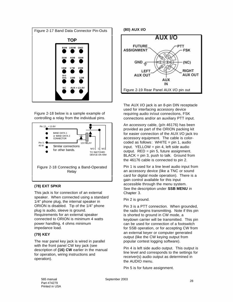
(80) AUX I/O
Figure 2-19 Rear Panel AUX I/O pin out
The AUX I/O jack is an 8-pin DIN receptacleused for interfacing accessory devicerequiring audio in/out connections, FSKconnections and/or an auxiliary PTT input.
An accessory cable, (p/n 46176) has beenprovided as part of the ORION packing kitfor easier connection of the AUX I/O jack troaccessory equipment. The cable is color-coded as follows: WHITE = pin 1, audioinput. YELLOW = pin 4, left side audiooutput. RED = pin 5, future assignment.BLACK = pin 3, push to talk. Ground fromthe 46176 cable is connected to pin 2.
Pin 1 is used for a line level audio input froman accessory device (like a TNC or soundcard for digital mode operation). There is again control available for this inputaccessible through the menu system.See the description under SSB MENU inChapter 3.
Pin 2 is ground.
Pin 3 is a PTT connection. When grounded,the radio begins transmitting. Note if this pinis shorted to ground in CW mode, akeydown carrier will be transmitted. This pincan be used for connection of a footswitchfor SSB operation, or for accepting CW froman external keyer or computer generatedoutput (like the CW keying output frompopular contest logging software).
Pin 4 is left side audio output. This output isline level and corresponds to the settings forreceiver(s) audio output as determined inthe AUDIO menu.
Pin 5 is for future assignment.

565 manual September 2003Part #74279Printed in USA
29
Pin 6 is right side audio output. This outputis line level and corresponds to the settingsfor receiver(s) audio output as determined inthe AUDIO menu.
Pin 7 is the FSK mark/space input. 5 volts =1 = mark, 0 volts = 0 = space. See FSKOPERATION section in Chapter 4.
Pin 8 has no connection.
(81) REMOTE
The REMOTE jack is used for connection ofthe model 302R accessory remoteencoder/keypad, allowing armchair tuningand control of transceiver functions.
(82) SERIAL DATA
The serial data connector is used for bothloading Flash-ROM updates into thetransceiver and for computer control ofradio. One of the great features aboutORION is that the latest version of the radiois always available from our firmware updatewebsite.
Complete computer control of the ORION ispossible via the SERIAL DATA connector.
A programmers reference guide and thelatest version of the radio firmware arelocated on Ten-Tec’s firmware update site atwww.rfsquared.com
Brief instructions on upgrading yourtransceiver are provided in Chapter 4.

565 manual September 2003Part #74279Printed in USA
30
Chapter 3 – MENU SYSTEM
ORION is equipped with a series of menus,each clearly labeled, for various transceiversettings. Most often used functions areavailable on the transceiver front panel viabuttons and knobs. Menus are used foritems for which only an occasional or one-time adjustment is needed.
To access the MENU system, press theMENUS button located to the upper righthand corner of the radio screen.
Figure 3-1 Menu Screen
A menu screen, as shown above in Figure3-1 will appear.
There are seven selectable menusaccessible after pressing the MENUSbutton. To the right side of the screen, thereare seven choices: TX, CW, VOX, RX,Other, SSB, Filtr. Each of these menus canbe accessed by pressing the correspondingbutton next to the right edge of the screen.In Figure 3-1, a button was pressed toaccess the TX menu. The TX annunciatoron the screen is highlighted and the menuoptions for TX are shown in text on thescreen.
In each menu, to scroll through the availablechoices on the screen, turn the large maintuning knob (“VFO A”) closest to the radioscreen. For each line item, to change thevalues, turn the MULTI knob. To exit themenu system and return to radio operation,press the MENUS button again.
(TX) TX MENU
The TX menu is used for controls related tothe ORION transmitter. They are describedline-by-line below.
Internal Tuner refers to the optional internalautomatic antenna tuner in ORION. Ifinstalled, the tuner can be enabled ordisabled with this line item. The internaltuner is operable on the ANT 1 connectiononly.
The internal tuner, when enabled, isactuated by RF. When changing bands, thetuner has no memory feature and will haveto be re-tuned using the TUNE button. Seedescription of (40) TUNE in Chapter 2.
Transmitter allows the ORION transmitterto be disabled. Use MULTI to set to on oroff.
Keying Loop 1 is used to enable the TXOUT 1 / TX EN 1 QSK keying loop asdescribed in chapter 2 under (67) TX OUT 1/ TX EN 1. Note: If the loop is turned on andno connections are made it will prevent theORION from transmitting.
Keying Loop 2 is used to enable the TXOUT 2 / TX EN 2 QSK keying loop asdescribed in chapter 2 under (69) TX OUT /TX EN 2. Note: If the loop is turned on andno connections are made it will prevent theORION from transmitting.
EXT T/R Delay 1 provides “hang time” for anon-QSK linear amplifier that has beenconnected to the AMP KEY 1 jack on therear of the ORION. This will prevent theamp from dropping out between words of aCW or SSB transmission. Also see thedescription of (66) AMP KEY 1 in chapter 2.
EXT T/R Delay 2 provides “hang time” for anon-QSK linear amplifier that has beenconnected to the AMP KEY 2 jack on therear of the ORION. This will prevent theamp from dropping out between words of aCW or SSB transmission. Also see thedescription of (68) AMP KEY 2 in chapter 2.
Transverter enables low level RF outputfrom the XVRT RF jack on the rear of thetransceiver. When turned on, no RF atregular power output will be transmitted

565 manual September 2003Part #74279Printed in USA
31
through the ANT 1 or ANT 2 connectors.The XVRT KEY jack for keying of thetransverter is also activated when this menuselection is turned to ‘on’.
Also see the transverter connection andoperation description in chapter 4.
The next 10 line items correspond toautomatic antenna selection per band.ORION provides the ability for the radio toautomatically select an antenna combinationwhen the band change keypad is used tochange amateur bands.
The available options are Ant1, Ant2,Ant1/RX, Ant2/RX and ---. The --- dashedline represents “no change” and whenchanging to a band marked as such, theradio will retain the previous antennaselection before the band change wasmade.
Ant1 and Ant2 automatically selects theantenna connected to ANT 1 or ANT 2 onthe rear panel for transceive operation.Ant1/RX will select both the antennaconnected to ANT 1 for transmit and thereceive-only antenna connected to AUX RXfor receive. Ant2/RX will select both theantenna connected to ANT 2 for transmitand the receive-only antenna connected toAUX RX for receive.
(CW) CW MENU
Figure 3-2 CW Menu
To select the CW menu, press the buttonimmediately adjacent to the screen next tothe CW selection (labeled AGC).
CW QSK Delay allows the operator to slowthe QSK action of the transceiver in CW
transmit. A higher value represents moretransmit/receive delay between individualtransmitted CW characters.
Internal Keyer can be turned on and off viathe menu system if desired. Please notethat when the radio is in a CW mode that thekeyer can also be turned on and off from thefront panel by pressing SP. See thedescription of (19) SP in Chapter 2.
CW Weighting refers to the 3:1 dit:dah ratioemployed by the CW keyer for transmittingMorse code. The length of each dah sent isthree times that of a dit, relative to thespacing between the elements. The defaultvalue is 100%, with an adjustable range of50% to 150%. As weighting increases inpercentage, dits and dahs become longer inlength, maintaining the 3:1 ratio. Asweighting percentage decreases, dits anddahs become shorter, maintaining the 3:1ratio.
Sidetone Pitch is the CW offset from carrierthat is used for listening to CW on the Orion.Turn the MULTI knob to adjust. This valueis also adjustable from the front panel whilepressing and holding the SPOT button andturning the MULTI knob simultaneously.Also see the description of (30) SPOT inChapter 2.
CW Rise/Fall allows the operator to adjustthe rise and fall time of the transmitting CWenvelope for more or less rise time. Theadjustable values are 3 ms to 10 ms,depending on whether the internal keyer orexternal keying is used, and the speed atwhich the internal keyer is set. The defaultvalue is 5 ms. Lower values like 3 ms willresult in a “harder” keying sound with aquicker slope from keying initiation to fullenvelope and back. Higher values result inmore gentler slopes for the CW transmitenvelope on the “make” and “break” andresult in a softer transmitted CW note.
For the internal keyer, 3 to 10 ms isavailable at speeds up to 30 WPM. Past 30WPM, the available values are 3 to 5 ms.Keying at “softer” rise and fall times above30 WPM can result in “mushy”, non-definitive sounding CW transmit.
For external keying, the rise and fall timesavailable are 3 ms to 5 ms regardless of thekeyer speed.

565 manual September 2003Part #74279Printed in USA
32
Key PTT in SSB determines whether or notthe ORION can be put into SSB transmitmode by a closure to the front or rear panelkey jacks. If set to “on”, pressing a CW key(or some other closure to ground connectedeither of the key jacks) will put the radio intotransmit in SSB modes. If set to “off”, theradio will not be put into SSB transmit inSSB modes when a closure to ground ispresent at one of the two jacks.
(VOX) VOX MENU
Figure 3-3 VOX Menu
The VOX menu is accessible by pressingthe button on the front panel immediately tothe right of the screen next to the “VOX”annunciator.
VOX Gain is the gain level required to putthe radio into transmit. This controldetermines how sensitive the VOX circuitryis to input from the microphone.
Anti-Vox is set to prevent tripping of theVOX circuitry. Set as needed to preventreceiver audio through the speaker fromputting the radio into transmit.
Vox Hang is used to define how long theVOX remains engaged after the end of atransmission. This is set to prevent theradio from cycling back and forth betweentransmit and receive during the course of anormal conversation.
(RX) RX MENU
Figure 3-4 RX Menu
The RX menu is accessible by pressing thebutton on the front panel immediately to theright of the screen next to the “RX”annunciator.
Sweep Range is used for setting the rangeof the real-time spectrum scope that isavailable on the main receiver. There are 5selectable widths of: 4.5, 9, 18, 36, and 72kHz.
AGC is Automatic Gain Control and is usedto provide a reasonably uniform output ataudio from incoming signal strengths ofvarying intensity.
One of the most useful, revolutionary newfeatures of ORION is fully programmableAGC. AGC action can be programmed totaste on each receiver for FAST, MED andSLOW settings, and a fourth setting, PROG,allows the user to adjust any and all of theAGC characteristics.
Refer to Figure 3-4 above. To adjust agiven parameter for each receiver, firstselect the desired AGC on the receiversbefore entering the menu system by usingthe AGC button (see (33) AGC in Chapter2).
For FAST, MED, and SLOW: The hang andthreshold parameters are fully adjustable.AGC hang is the amount of time that theAGC remains actuated before decay begins.Threshold is the point at which a signal of agiven strength (expressed in microvolts) willactuate the AGC system. The thresholdvalue in the AGC system acts like an IF gaincontrol for the receiver chain – turn the value

565 manual September 2003Part #74279Printed in USA
33
low and the receiver gain comes up, as dothe signal levels. Decay is used todetermine how fast the IF gain increases inthe absence of a signal above the thresholdvalue.
The hang value for FAST, MED, and SLOWis adjustable from 0 to 10.92 seconds. Thethreshold value for FAST, MED, and SLOWis adjustable from 0.37 uV to 191.48 uV.The decay values available are FAST, 80-200 dB/second, MED, 20-80 dB/second,SLOW 5-20 dB/second.
The factory default values for FAST, MED,and SLOW are FAST: hang 0.00, decay 80dB/s, threshold 3.03 uV, MED: hang 0.00,decay 40 dB/s, threshold 3.03 uV, SLOW:hang 0.00, decay 10 dB/s, threshold 3.03uV. These default settings apply to both themain and sub receivers. Any default valuefor a given AGC setting (FAST, MED, andSLOW) can be instantly restored to factorydefault value merely by pressing the MULTIknob encoder toward the front panel whilethe parameter is highlighted in the menu.
The PROG (programmable AGC) settingprovides full adjustment of all parameters inthe AGC system. In addition to the hangand threshold values being fully adjustableas they are with FAST, MED, and SLOW,the programmable AGC setting allows thedecay rate to be adjusted over its full rangefrom 5 to 2000 dB/second.
AGC is an important characteristic of overallreceiver performance for contesting andweak signal DXing. Please also read thesection in Chapter 4 of this manual titled“Optimal Uses of ORION Receiver forWeak-Signal DXing and Contesting”.
PBT Track and BW Track are used tosimultaneously set the PBT and BW valuesfor each receiver with one turn of the MULTIknob. The default value is “off”, allowing thePBT and BW values to be adjustedseparately by receiver. If it is desirable toadjust both PBT and BW on both receiversat the same time, this control can be set to“on”. Additionally, BW setting can becopied between VFO A and VFO B whenusing the A>B, B>A, or A/B buttons on thefront panel if this value is set to “on” (defaultis that BW information is not copied betweenVFOs when frequency information isexchanged).
Hardware NB allows the hardware noiseblanker available for the main receiver to beturned on and off. This additional noiseblanking system for the main receiver onlycan either be used together with orindependently of the software noise blanker.When activated, the area just above the NBbutton on the botton of the radio screen willshow the annunciator :H next to any valueset for the software noise blanker. Thehardware noise blanker can also beactivated without going into the menusystem by pressing and holding the NBbutton for two seconds. Also see thedescription of the software noise blanker inChapter 2 under (23) NB.
Main RX Sql is the squelch threshold for themain receiver. It represents a signalthreshold measured in -dBm. The higherthe value, the more receive signal will beneeded to break the squelch. Adjust byturning the MULTI knob.
Sub RX Sql is the squelch threshold for thesub receiver. It represents a signalthreshold measured in -dBm. The higherthe value, the more receive signal will beneeded to break the squelch. Adjust byturning the MULTI knob.
PBT/BW Step allows the operator to choosein what step size the PBT/BW encoderselects filter bandwidths and PBT values.The available choices are 10, 50 and 100Hz.

565 manual September 2003Part #74279Printed in USA
34
(OTHER) OTHER MENU
Figure 3-6 Other Menu
The Other menu is used for ORIONfunctions that do not fit into one of the othermenu categories.
Remote Pod F1, Remote Pod F2, andRemote Pod F3 refer to the control of radiofunctions available via the F1, F2, and F3buttons on the accessory model 302Rremote encoder/keypad available forORION. If you do not have the 302Rconnected, they will have no function.
To scroll through the available choices foreach of Remote Pod F1, Remote Pod F2,and Remote Pod F3, turn the MULTI knob.
VFO A/B duplicates the function of the A/Bbutton on the front panel (see (60) A>B,B>A, A/B in Chapter 2). This flips the twofrequencies shown, copying A to B and B toA.
Step duplicates the function of the STEPbutton on the front panel (see (31) STEP inChapter 2). Unlike the front panel STEPbutton, the step sizes available are selectedvia repeat pushing of the F1, F2, or F3button depending on which is being used.The radio will cycle through the sevenavailable step sizes.
Mode duplicates the function of the MODEbutton on the front panel (see (27) MODE inchapter 2). Unlike the front panel MODEbutton, the step sizes available are selectedvia repeat pushing of the F1, F2, or F3button depending on which is being used.The radio will cycle through the sevenavailable modes.
Sweep on/off duplicates the function of theSWEEP button on the front panel (see (32)
SWEEP in Chapter 2). The real-timespectrum sweep on the main receiver canbe turned on and off.
USER 1 and USER 2 are duplicates of thefront panel USER 1 and USER 2 buttons(see (21) USER 1 and USER 2 in Chapter2). These allow retrieval of the profilememories that are stored in USER 1 andUSER 2.
Send 1, Send 2, and Send 3 are duplicatesof the SEND 1, SEND 2 and SEND 3buttons found on the front of the ORION(see (20) SEND 1, SEND 2, SEND 3 inchapter 2). They are used for sendingmemory information stored in either the CWkeyer or voice memories.
VFO A Ent and VFO B Ent allow directfrequency entry off the keypad for eitherVFO A or VFO B.
The Rem Pod Enter setting determineswhere a band change from the keypad issent (VFO A or VFO B). The ten buttonkeypad on the 302R accessory duplicatesthe band change keypad on the ORIONunless a function button has first beenpushed for direct frequency entry. Push “9”to change to 40m, “7” to change to 160m,etc. Note that the 302R buttons are notarranged in the same numerical order as thekeypad on the ORION; it is the location ofthe button in the matrix rather than thenumber on the button on the 302R thatdetermines to what band the radio ischanged.
Menu Delay is used to set the encodertuning rates and button responses whileusing the menus.
Contrast is used to determine the screencontrast for either white/black or black/whitedepending on which way the screen istoggled. Default is 50%, maximumreadability is generally in the 50 to 60%range.
VFO-A Enc Rate and VFO-B Enc Ratehave settings of “fast” and “slow”. Unliketuning STEP as set via the STEP button, theRate controls are used to determine howmany steps per revolution of the two maintuning knobs are made. The “fast” rate is 4xthe “slow” tuning rate
Like the main tuning knob rates, CW RITRate and SSB RIT Rate are used to vary

565 manual September 2003Part #74279Printed in USA
35
the rate, but not the step size, of the RITencoder. The “fast” rate is 4x the “slow”tuning rate.
If the optional model 302R encoder/keypadis in use, POD Enc Rate can be used tocontrol the tuning knob rate. The “fast” rateis 4x the “slow” tuning rate
LCD Display is used to toggle the radioscreen between a white background withblack alphanumeric information and a blackbackground with white alphanumericinformation. Turn the MULTI knob to toggle.
FSK Tx Data is used to to determinewhether the MARK tone in FSK operation ison the high tone (2295 Hz) or low tone(2125 Hz). The standard is for FSK to usethe low tone for MARK. See the descriptionfor FSK OPERATION in Chapter 4.
(SSB) SSB MENU
Figure 3-7 SSB Menu
The SSB menu is used for adjustment ofSSB transmit options.
Aux Input Gain is used for adjusting audiogain from an accessory device using the linelevel aux input available on pin 1 of the rearpanel AUX I/O connector.
TX Filter BW controls the SSB transmit filterbandwidth. The maximum bandwidth usableby ORION is 3.9 kHz. Wider bandwidths(above 3 kHz) have a more full-range soundto transmitted SSB audio; narrowerbandwidths are “communications grade”SSB audio. Typical communications audiofor TX Filter BW would be 2.7 kHz.
L.F. Rolloff refers to the point where lowend audio response starts for transmittedSSB audio. For example, if TX Filter BW is
set to 3000 Hz and L.F. Rolloff is set to 200Hz, the frequency response of thetransmitted signal is 200 Hz on the low endto 3200 Hz at the high end. Moving L.F.Rolloff to 100 Hz would move the transmitpassband to 100 Hz to 3100 Hz for a 3000Hz bandwidth. The available values are aminimum of 50 Hz to a maximum of 300 Hz.
TX Audio Source allows the radio to haveaudio input through either the front panelmic jack or via the AUX input on pin 1 of therear panel AUX I/O connector. Theavailable choices are MIC, AUX or BOTH.
Please also see the description for settingup SSB transmit audio in Chapter 4.
(FILTR) FILTER MENU
Figure 3-8 Filter Menu
Please refer to the discussion of filtering inChapter 1. ORION provides for up to sevenavailable mode-appropriate I-F roofingfilters, not to be confused with traditionalbandwidth filtering as provided for in DSP.Optional roofing filters of 1.8 kHz, 500 Hz,and 250 Hz in the ORION need to beactivated to be used by the operator.Please note: If you activate an optional filterposition and no filter is installed, the radiowill mute on receive!
Activating the optional filters is simple. Foreach of the 1.8 kHz, 500 Hz, and/or 250 Hzoptional filters that you have installed, usethe MULTI knob to change the setting from“no” to “yes”.
Roofing filters can automatically be selectedby the radio or the operator has the option ofoverride to select one specific filter to be

565 manual September 2003Part #74279Printed in USA
36
used at all times. The available choices are20 kHz, 6 kHz, 2.4 kHz, 1.8 kHz (if installed),1 kHz, 500 Hz (if installed), 250 Hz (ifinstalled).
For automatic selection of appropriateroofing filters, put the Xtal Filter setting onAUTO. When using the DSP BW filtering inthe ORION (see description of (41) PBTB/W ENCODER in Chapter 2), as athreshold for each filter is crossed, theroofing filters will automatically be selected.Example: After selecting AUTO, pressMENUS to exit out of the menu system andreturn to normal radio operation. As theDSP bandwidth is narrowed, the filters willbe selected or de-selected at a valuesomewhat below that of the roofing filter.For example: the threshold where the 6 kHzfilter switches out to the 2.4 kHz filter inAUTO mode is 2000 Hz. At 1990 Hz DSPBW, the 2.4 kHz filter is active. At 2000 Hz,the 6 kHz roofing filter is active. On thescreen, the roofing filter is represented by ahorizontal line on top of the DSP BW filtershape. The line will widen or narrow as theroofing filters switch in and out.
It is possible to override the AUTO settingand use one specific filter at all times. To doso, turn the MULTI knob while Xtal Filter isis highlighted in the menu and pick a roofingfilter. Regardless of DSP BW setting, thisselected filter will be in use as the roofingfilter. Remember: optional roofing filters,must be installed and enabled. Selecting anon-installed filter will mute the receiver. Ifselecting an installed optional filter that isnot enabled, the next highest value will bethe actual filter in use.
Each of the 250 Hz and 500 Hz optionalroofing filters used in ORION must becentered. While DSP very accurately repeatfrom unit to unit, crystal filters do notbecause of individual unit manufacturingtolerances. Set your CW offset to desiredvalue via the CW MENU. Tune in a carrierof reasonable strength (S7 is good), at yourCW offset. Use the Xtal Filter control in themenu to select the filter you want to center.Then move down to either 500 Hz C.F. Adjor 250 Hz C.F. Adj depending on your filterselection. Adjust the MULTI knob for areceived signal peak. You will not have to
re-adjust these unless you do a subsequentmaster reset of the radio.

565 manual September 2003Part #74279Printed in USA
37
Chapter 4 – OPERATION ANDACCESSORY CONNECTION EXAMPLES
BASIC TRANSCEIVE OPERATION
Refer back to the operating instructions inChapter 2 for (8 – 13) VFO ASSIGNMENTS.The most important point to consider is thatVFO’s are not receivers. Both receivers canbe assigned to one VFO if desired.
Typical transceive operation would be tohave the main receiver and the transmitteron VFO A, and the subreceiver on VFO B.
To do so, press buttons as shown below inFigure 4-1. Under VFO A, the buttons nextto TX and RX are lit, under VFO B the SUBRX button is lit.
Figure 4-1. VFO selection for transceive withmain RX/TX on VFO A, subreceiver VFO B.
VFO A is always the main tuning knobclosest to the screen – VFO B is always themain tuning knob at the far right of theORION.
Turn the MAIN AF knob to increase mainreceiver volume. Turn the SUB AF knob toincrease sub receiver volume. Either ofthese can be muted by pressing the encodertowards the radio face. To unmute, press orturn the knob.
The AUDIO menu determines the mix ofmain receiver and sub receiver audio heardthrough the speaker or the headphones.See the Chapter 2 description for (36)AUDIO.
Antenna selection is determined by thematrix of six buttons at the far left of the
radio. A complete description is provided inChapter 2 under (2 –7) ANTENNAASSIGNMENTS.
OPERATING SPLIT FREQUENCY
Often DX stations will be listening on onefrequency while transmitting on another.The two receivers and two VFO’s in ORIONpermit the operator to listen to both the DXstations frequency and the frequency wherethe DX station is listening for callssimultaneously. There is no SPLIT button,but setting up split frequency operation onlyrequires pressing the A>B button as shownbelow.
An example using the typical transceivesetup of main RX/TX on VFO A andsubreceiver on VFO B: A DX station istransmitting on 14.195 MHz and listening forcalls on 14.210 MHz. Tune in the DX stationon 14.195 on VFO A. Press A>B toequalize the frequencies on the two VFO’s.Tune VFO A to 14.210. You are nowlistening to the DX station on thesubreceiver on VFO B on 14.195 and areready to transmit (and listen) on 14.210using the main receiver.
For weak DX stations operating splitfrequency, it is probably advantageous touse the main receiver for listening to the DXstation and using the subreceiver frequencyfor monitoring the pileup and your transmitfrequency. Starting from the same exampleof main RX/TX on VFO A and subreceiveron VFO B, DX station on 14.195 listening on14.210: Tune in the DX station on 14.195on VFO A. Press A>B to equalize thefrequencies on the two VFO’s. Tune VFO Bto 14.210. Press the button next to TX,under VFO B. You are now listening to theDX station on the main receiver on 14.195on VFO A, and are listening and ready totransmit on 14.210 with the subreceiver andtransmitter on VFO B. See Figure 4-2 forassignment of VFO buttons.

565 manual September 2003Part #74279Printed in USA
38
Figure 4-2. Split frequency operation withDX station being received on main receivervia VFO A, subreceiver monitoring of pileupand transmit frequency on VFO B.
OPERATING THE INTERNAL ANTENNATUNER (if installed)
Your ORION may be equipped with aninternal automatic antenna tuner. Ifinstalled, the tuner is active on the ANT 1jack only, and has a load impedance rangeof 6 to 800 ohms (up to 10:1 SWR).
The tuner can be enabled or disabled fromthe menu system. The default condition isto have the tuner enabled. To enable ordisable, press MENUS then select the TXmenu. The first line item in the TX menu isInternal Tuner. Use the MULTI knob to turnthe tuner on or off.
The tuner is activated by pressing the TUNEbutton on the front panel. The rig willtransmit a keydown CW carrier atapproximately 20 watts output. The tunerwill activate and tune. When finished, theCW carrier will stop and TUNED will appearon the screen just under the TUNE button.
The tuner will usually stop at a value of 1.5:1SWR or lower. Occasionally it may presenta slightly higher SWR after tuning. This isnormal, and the transceiver will still transmitat full output power with no foldback.
The tuner does not automatically reactivatewhen presented with a higher SWR afterchanging frequency. If the tuner was tunedon 14.025 MHz and you later moved to14.200 MHz, the tuner may require re-tuningand can be activated again with the TUNEfeature.
There is no memory feature; the tuner willnot retain the last setting for a particularband or frequency.
CONNECTING AN EXTERNAL LINEARAMPLIFIER
Whether you have an amplifier that is fullbreak-in, and how the full break-in isaccomplished, will determine the method forconnecting the linear to ORION.
Two sets of keying outputs are provided forthe two available antenna jacks on the radio.AMP KEY 1 and TX OUT / TX EN 1 areused for a linear connected via the ANT 1jack. AMP KEY 2 and TX OUT / TX EN 2are used for a linear amplifier connected viathe ANT 2 jack. RF appears approximatel15 mS after closure of either AMP KEY 1 orAMP KEY 2.
Non-QSK linear amplifiers or QSK linearsthat do not employ the use of a keying loopare keyed from the AMP KEY 1 and AMPKEY 2 jacks (see (66) AMP KEY 1 and (68)AMP KEY 2 in chapter 2). Connect the PTTkeying line of your linear amplifier to theAMP KEY 1 or AMP KEY 2 jack as desiredusing a shielded cable with RCA-style malephono connectors at each end.
The external amplifier key line should notapply more than +100V (output inactive) norshould it draw more than 250 mA (outputactive). Many older linear amplifiers likethose manufactured by Collins, Drake, andHeathkit have a higher voltage on thekeyline. Such amplifiers require a relay ortransistor switch between either ORIONAMP KEY jack and the amplifier PTTkeyline. If you are unsure if your amplifier issuitable, please consult the operator’smanual for your amplifier or contact the Ten-Tec service department.
An adjustable delay is available for each ofthe AMP KEY jacks. These are titled EXTT/R Delay 1 and EXT T/R Delay 2. Thesegive the operator the ability to have theamplifier keyed longer by the radio,preventing drop outs between words of SSBor CW operation. EXT T/R Delay 1 andEXT T/R Delay 2 are found in the TXsubmenu under MENUS.
Some QSK linear amplifiers incorporate theuse of a full break-in keying loop. Ten-Teclinear amplifiers use a full break-in keying

565 manual September 2003Part #74279Printed in USA
39
loop to assure proper sequencing of thekeying between the radio and the amplifier.
To use the ORION with a full break-in linearamplifier incorporating a keying loop, usethe TX OUT 1 / TX EN 1 or TX OUT 2 / TXEN 2 jacks as appropriate for an ampconnected to the ANT 1 or ANT 2 jacks.
Connect TX OUT 1 to the keying loop inputon your amp. On Ten-Tec amplifiers, thecorresponding jack is marked KEY IN.Connect TX EN 1 to the keying loop outputon your amp. On Ten-Tec amplifiers, thecorresponding jack is marked KEY OUT.Place the amp in QSK mode. The amplifierwill be used in all modes in the QSKposition.
Please note: To use a full break-in keyingloop, it must be enabled from the MENUS.The keying loops are turned on and off viathe TX submenu in the MENUS (see the TXMENU description in Chapter 3). If the loopis turned on, and no connections are made itwill prevent the ORION from transmitting.
TUNING UP AN EXTERNAL LINEARAMPLIFIER
The TUNE button on the front panel can beused for initial linear amplifier tune-up. If anautomatic antenna tuner is installed in yourORION, go into the TX MENU and disable it.Pressing the TUNE button will provideapproximately 20 watts of keydown CWcarrier output to be used for an initial tune-up of your linear.
It may be desirable to increase the keydownpower output when tuning your amplifier. Todo so, press the PWR button after pushingthe TUNE button. Power output will movefrom the low power setting to whatever levelthe PWR control has been set at with theMULTI knob. Repeat operation will requirepushing TUNE then PWR again for thehigher output value.
FACTORS THAT AFFECT THE SOUNDOF SSB TRANSMIT AUDIO AND THEIRADJUSTMENT
One of the features of ORION is a lot offlexibility afforded the operator for thedesired sound of SSB transmit audio. Manypossible settings are available so thatoperators with different styles (orphilosophies) can adjust the radio the waythey want it to sound. Obviously, the
operator who favors rich, full-soundingtransmit audio is not going to have the sameneeds as the DXer who wants maximum“oomph” to try and break an SSB pileup.
There are several controls that interact onORION for SSB transmit audio. Everyoperator is different; we use differentmicrophones, the timbre of voices aredifferent, distance from the microphone willvary. What we intend below is to describewhat is used to tailor transmit SSB audio,and then encourage the operator toexperiment with the settings to find thesound they want.
A monitor function (button marked MON) onthe front panel has been provided for theoperator to listen to the sound of actualtransmitted SSB audio. We recommendusing headphones while using the MONcircuit to prevent microphone/speakerfeedback. See the description of (18) MONin Chapter 2.
There are five radio controls used for SSBtransmit audio. 1) Transmit bandwidth,which is adjusted using the TX Filter BWcontrol in the SSB menu. 2) Low frequencyrolloff, adjusted with the L.F. Rolloff controlin the SSB menu. 3) Transmit equalization,labeled TX EQ, which is adjusted in theAUDIO submenu found by pushing theAUDIO button on the front panel. 4) Micgain, adjusted via the front panel MICbutton. 5) Speech processing, adjusted viathe front panel SP button.
Transmit bandwidth is both the frequencyresponse of the transmitted signal and theamount of spectrum occupied by that signal.Typical communications-grade audio forSSB is in the 2.4 to 2.7 kHz range. Some“hi-fi” SSB enthusiasts have beenexperimenting with larger transmitbandwidths in an effort to improve thequality of audio transmitted, and ORION hasbeen provided with the ability to transmit onSSB with a maximum bandwidth of 3.9 kHz.Please see the note toward the end of thissection about wide SSB transmit bandwidthsand their potential ramifications.
Set the TX Filter BW in the SSB menu to anappropriate value based on your operatingpreferences. For communications- gradeaudio, we recommend starting the ORIONtransmit bandwidth at 2.55 kHz (2550 Hz).
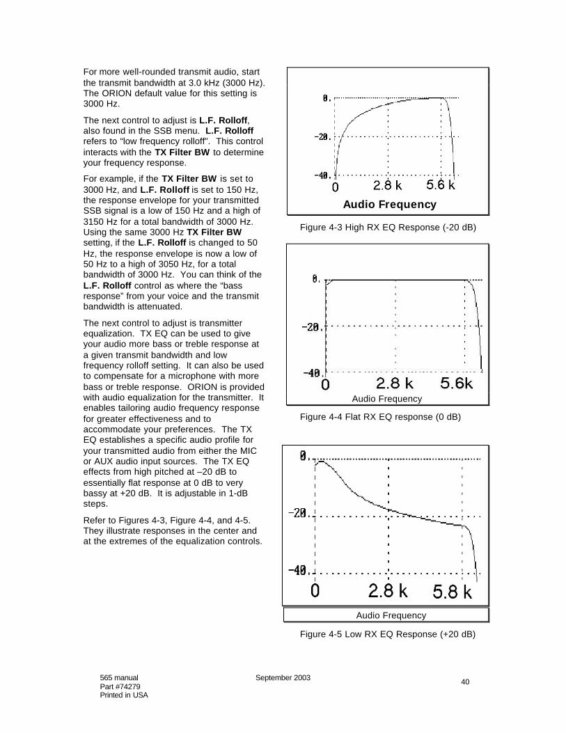
565 manual September 2003Part #74279Printed in USA
40
For more well-rounded transmit audio, startthe transmit bandwidth at 3.0 kHz (3000 Hz).The ORION default value for this setting is3000 Hz.
The next control to adjust is L.F. Rolloff,also found in the SSB menu. L.F. Rolloffrefers to “low frequency rolloff”. This controlinteracts with the TX Filter BW to determineyour frequency response.
For example, if the TX Filter BW is set to3000 Hz, and L.F. Rolloff is set to 150 Hz,the response envelope for your transmittedSSB signal is a low of 150 Hz and a high of3150 Hz for a total bandwidth of 3000 Hz.Using the same 3000 Hz TX Filter BWsetting, if the L.F. Rolloff is changed to 50Hz, the response envelope is now a low of50 Hz to a high of 3050 Hz, for a totalbandwidth of 3000 Hz. You can think of theL.F. Rolloff control as where the “bassresponse” from your voice and the transmitbandwidth is attenuated.
The next control to adjust is transmitterequalization. TX EQ can be used to giveyour audio more bass or treble response ata given transmit bandwidth and lowfrequency rolloff setting. It can also be usedto compensate for a microphone with morebass or treble response. ORION is providedwith audio equalization for the transmitter. Itenables tailoring audio frequency responsefor greater effectiveness and toaccommodate your preferences. The TXEQ establishes a specific audio profile foryour transmitted audio from either the MICor AUX audio input sources. The TX EQeffects from high pitched at –20 dB toessentially flat response at 0 dB to verybassy at +20 dB. It is adjustable in 1-dBsteps.
Refer to Figures 4-3, Figure 4-4, and 4-5.They illustrate responses in the center andat the extremes of the equalization controls.
Audio Frequency
Figure 4-3 High RX EQ Response (-20 dB)
Audio Frequency
Figure 4-4 Flat RX EQ response (0 dB)
Audio Frequency
Figure 4-5 Low RX EQ Response (+20 dB)

565 manual September 2003Part #74279Printed in USA
41
The displayed setting of the equalizersrefers to the amplitude in dB (at about 100Hz) relative to the highest frequency in thepassband. For example, the –20 dB settingproduces –20 dB at 100 Hz relative to 0 dB.
Generally, the TX Filter BW , L.F. Rolloff,and TX EQ controls are set once and notadjusted again unless you changemicrophones or want to experiment withdifferent SSB sound.
The two most-used SSB transmit controlswill be mic gain (accessible from the MICbutton on the front panel) and the speechprocessor (accessible from the SP button onthe front panel).
Mic gain is set by pressing the MIC buttonand talking into the microphone. When youhave reached proper ALC, the red ALC LEDlocated next to the S-meter on the front ofthe radio will flash on voice peaks. Adjustthe mic gain upward until the ALC light isflashing on and off while you aretransmitting. Different microphones willrequire more or less gain. The Ten-Tecmodel 706 communications deskmicrophone will require a small amount ofgain. Microphones like those manufacturedby Heil Sound (the Heil/Ten-Tec Studio One,for example) will require more gain. This isnormal.
Speech processing (SP) is provided to givethe operator more “punch” to the transmittedsignal. Speech processing increases theaverage amplitude relative to the peaks foran increase in average power transmitted.Press the SP button (if desired) and use theMULTI knob to adjust the speech processinglevel. Speech processing is generally notused for higher-fidelity SSB audio; its use isprimarily for added intelligibility forcommunications-grade SSB audio. It is alsopossible with high levels of speechprocessing and combinations of microphoneand other settings available to send thetransmitter into distorted SSB output. Usethe MON function to listen to what you aretransmitting and avoid this.
The speech processor used in the ORION isa true RF compressor, DSP generated.Human voices have peak-to-average ratiosas high as 15 dB. At 100 watts PEP output,
the average output power might be as littleas 3 watts! RF compression raises theaverage output power and tends to improveintelligibility by bringing out subtle parts ofspeech. With a digitally generated RFspeech processor, we have the advantageof calculating the RF envelope before themodulation is performed. Microphone audiois sampled and converted to an analyticsignal, and an equation is used to computethe envelope.
Note on wide SSB transmit bandwidths:Audio fidelity generally improves with theuse of wider SSB transmit filtering. Using a3.0 kHz or higher bandwidth will have amore “well-rounded” audio response than anarrower bandwidth. As transmit bandwidthwidens, so does the potential forinterference with stations using adjacentfrequencies.
Part 97 of the FCC regulations governingamateur radio operation does not specify amaximum transmit bandwidth usable byamateurs for SSB communication.However, FCC regulation 97.307(a) requiresamateur stations not to occupy morebandwidth than is necessary for theemission type being transmitted inaccordance with good amateur practice.Regulation 97.307(b) requires thatemissions outside the necessary bandwidthmust not cause splatter interference tooperations on adjacent frequencies.
While these are broad regulations subject tointerpretation, the responsibility forcomplying with the regulations rests with theoperator. Using an SSB transmit bandwidthwider than necessary for communicationsand causing interference to adjacentstations while doing so is specifically whatthese regulations are addressing. Insummary, what may be an acceptablebandwidth on a given band at a given timemay not be on another band at another time.
See Figure 4-6 for some initial settings forvarious microphones. Remember yourresults will vary, and these are justsuggested starting points.

565 manual September 2003Part #74279Printed in USA
42
InputSource
InputDevice MODE
MICGain
AUXGain
TXEQ
StudioOneMic.
MIC SSB 60 zero -14 dB
Ten-Tec706 Desk
Mic.MIC SSB 40 zero 0 dB
SoundCard
InterfaceAUX PSK31 zero 75 -14 dB
SoundCard
InterfaceAUX MFSK zero 55 0 dB
Figure 4-6 Initial Suggested Microphone Settings
SETTING UP ORION FOR AM TRANSMIT
The same factors that affect SSB transmitalso come into play for AM transmitoperation as well. Speech processor, lowend rolloff, TX bandwidth, mic gain, and TXEQ are all used for AM operation as well.
Transmit bandwidth in AM operation isdoubled from that shown in the SSB menu.AM transmit bandwidth is still set from theSSB menu, but the value selected isdoubled for AM operation. To select a 6 kHzAM transmit bandwidth, select 3000 Hz inthe SSB menu as the transmit bandwidth.
Carrier amplitude for AM operation is setautomatically by ORION. The PWR controlon the front is used for PEP output powersetting in AM operation. A value of 100would correspond to 100 watts PEP AMoutput, or 25 watts carrier power maximum.
FSK OPERATION
Selection of the FSK mode will allow theOrion to operate true FSK RTTY. The FSKcircuitry is controlled through the rear AUXI/O jack on the rear apron of the Orion.
Pin 7 on the I/O jack is the MARK/SPACEinput. This input is typically connected tothe FSK output on a modem or terminalunit. The Orion receives FSK using lowersideband. The center of the filter passbandis preset so any bandwidth filter used will becentered on the standard FSKMARK/SPACE 2125/2295 Hz tones.
The Orion display indicates the transmitMARK frequency. There is also auser-control called FSK Tx Data in theOther menu for selecting whether the MARKis the low tone or high tone (the standard islow tone). This allows the Orion to be usedwith either TTL or open-collector keyingschemes.
The monitor function is available in FSKmode and may be used to monitor thetransmitted tones. (See (18) MON inChapter 2).
Note: Early ORION transceivers supportedTTL data keying only and will require a veryminor modification to operate with open-collector data keying. Check withthe Ten-Tec service department for details.
TRANSVERTER HOOKUPS
ORION provides the ability for a VHFtransverter to be connected to the rear panelvia the XVRT KEY, XVRT RF, and AUX RXjacks on the ORION rear panel.
Both the XVRT KEY and XVRT RFtransverter support connections areactivated via the TX menu. Enter the TXMENU (see description under TX MENU inChapter 3), and use the MULTI knob to turnthe transverter output on. This will activateboth the XVRT KEY jack and send RFoutput through the XVRT RF jack.

565 manual September 2003Part #74279Printed in USA
43
VHF/UHFTRANSVERTER 565 TRANSCEIVER
V/UHF RX
V/UHF TX
XVRTR KEY XVRT KEY
XVRT RF
RX ANT
COAX
SHIELDED WIRE
(Split antenna mode)
Figure 4-7 Connecting a Transverter
Basic connection for a transverter is shownin Figure 4-7. The receive side of thetransverter is connected to the AUX RX jack.On ORION, select VFO A for transceiveoperation by pressing the TX and RXbuttons on the front panel in the VFO Acolumn under the S-meter. Select RX ANTfor MAIN RX/TX on the front panel.
The transmit side of the transverter isconnected to the XVRT RF jack. XVTR RFprovides a low level output RF output ofapproximately +15 dBm - this output is ALCcontrolled and is adjustable from +5 to +15dBm by using the PWR and MULTI controlwhen the transverter output has beenactivated in the menus.
XVRT KEY is for the PTT connection of yourtransverter.
It may be desirable to employ the use of asequencer for proper key sequencing oftransverter, radio, linear amplifier, etc.ORION can easily be used with asequencer. The last relay output to close onthe sequencer should be connected to theTX EN 1 jack on the rear of the ORION. Gointo the menus and turn on Keying Loop 1.This keying loop will prevent the radio fromtransmitting until a closure to groundappears at the TX EN 1 jack. By connectingthe last relay to close on the sequencer tothe TX EN 1 jack, the operator will haveensured that all required keying connectionshave been closed prior to RF appearing atthe output of the XVRT RF jack.
DIVERSITY RECEPTION
Because the ORION has the ability to haveboth receivers tuned by a single VFOsimultaneously, and because both receiverscan be split out to different antennas, aworld of possibilities for diversity receptionare opened.
First, a definition of “diversity reception”:Radio reception in which a signal is obtainedby combining or selecting signals, from twoor more independent sources, but whichmay vary in their fading characteristics atany given instant. Good examples would bethe use of one horizontal and one verticalantenna or two horizontal antennasseparated by one wavelength or more.
It has been shown from studies that weakand/or fading signals are more copyablewhen they are heard from two sourcessimultaneously rather than only one. Assignals fade, if another source is available tosimultaneously monitor the signal, the fadingeffect can be somewhat compensated for.This is useful not only for the weakestsignals when chasing DX, but for normalcommunication where signal levels are fairlyreadable but still subject to some QSB.
Because ORION allows you to tune tworeceivers with one VFO, diversity receptionis possible using the two receivers on twoseparate antennas.
First, put both receivers on the desiredamateur frequency on VFO A. To do this,merely press all three of the buttons in theVFO A column directly under the S-meter.Now both receivers and the transmitter aretuned by the VFO A tuning knob. PressANT 1 for MAIN RX/TX and ANT 2 for SUBRX. See Figure 4-8.
Figure 4-8. Diversity reception with bothreceivers on VFO A. Main receiver andtransmitter are utilizing ANT 1. Subreceiveron VFO B is utilizing ANT 2.
In the AUDIO menu, either combine theaudio outputs of the two receivers in bothheadphones by selecting “Both” for Sub andMain RX audio, or put one receiver in eachear by selecting Main: Left and Sub: Right

565 manual September 2003Part #74279Printed in USA
44
The ORION is now set up for diversityreception with the main receiver andtransmitter on ANT 1 and the subreceiver onANT 2.
For low band DXing, it may be desirable tocombine the outputs of the two receiversfrom two different receive antennas whilehaving the transmitter use a third antenna.This is accomplished by connecting receive-only antennas to both ANT 2 and the RXANT jacks on the rear panel, and using ANT1 for transmitting.
Put the subreceiver on ANT 2, the mainreceiver on RX ANT and the transmitter onANT 1 by pushing buttons on the front panelso they light up as shown in Figure 4-9.Again put both receivers and the transmitteron VFO A.
Figure 4-9. Diversity reception. Mainreceiver on VFO A is using RX ANT jack.Transmitter on VFO A is using ANT 1.Sub receiver on VFO B uses a secondreceive antenna connected to ANT 2.
Using this configuration, both receivers canuse independent receive antennas while thetransmitter uses a separate TX antenna, allon the same frequency. Both receivers aretuned simultaneously by turning the VFO Amain tuning knob.
WEAK SIGNAL DX RECEPTION,CONTEST OPERATION AND THE ORION
With recent transceivers, an operatortypically would set CW for a low orcomfortable offset, select a narrowbandwidth filter (like 250 Hz), turn AGC toeither “fast” or “off”, use some setting forDSP noise reduction and start listening forweak signals. Which is fine – except that“typical” settings like this used for other
radios simply won’t use Orion to itsmaximum capabilities.
An important point to ponder: There is noone setting for RX combination (definedas roofing filter, DSP bandwidth filter,DSP NR, and AGC together) that is thecorrect one for Orion. There are goodplaces to start – and by understanding howthe operation of the high dynamic rangereceiver in Orion is different from othertransceivers will set you on the correct pathtoward optimum use.
Think this through logically. Band conditionsalways vary, noise always varies, signalsalways vary. If you set a transceiver for oneoptimal setting to use it for variableconditions, would it seem logical that theoperator would be using the transceiver toits optimum capability each and every time?
Refer back to the above definition of the useof a crystal roofing filter. The roofing filter isused for keeping strong closeby signals fromcompromising receiver performance.Listening to a weak signal on a quiet banddoes not meet the definition of need for atight roofing filter. On a band where fewsignals are present other than a desiredtarget weak signal, only a wide roofing filterwould be necessary. Putting in the 250 Hzroofing filter when listening to a single weaksignal on the low bands gains nothingadditional. In fact, it could hurt your ability tohear a noise floor level weak signal. Why?Among other reasons, all narrow bandwidthfilters suffer from insertion loss – and in theOrion, like other transceivers have for manyyears, we use an amplifier to compensatefor crystal filter loss. A 250-Hz filter is goingto have slightly more loss than a 500-Hzfilter. Both of these narrow filters havemore loss than the 1 kHz roofing filter. Theloss, after preamp compensation, is about 2dB. No loud signals nearby = no need fora tight roofing filter. Regardless of DSPbandpass filter setting, we’d recommendusing a wider roofing filter as acceptable forweak signal DXing. The DSP bandpassfiltering does not vary in gain down to theminimum setting of 100 Hz. Therefore, ifthere is no offending signal within 1 kHz,setting the roofing filter at 1 kHz andnarrowing the DSP bandwidth to any desiredvalue is by far the best setup for Orion forsingle signal DXing.

565 manual September 2003Part #74279Printed in USA
45
Of course, if you have a pileup 1 kHz away,perhaps a tighter roofing filter is warrantedto keep those loud callers fromcompromising close-in performance.
That’s fine – but make sure that the crystalroofing filters are centered.
DSP noise reduction in the Orion interactssomewhat with the digital AGC system.Here is why: when turning on the noisereduction, without changing digital AGC, thereceiver will get very quiet, very quickly.This is not the desired effect of noisereduction! The desired effect is to identifywhat is signal and what is noise and improvethe ratio between the two, rather thanmaking the whole receiver quieter, signalsand noise. When DSP NR is selected,digital AGC artificially reduces the thresholdsetting of the digital AGC – and you willnotice that the overall noise level canincrease – but signal-to-noise ratioimproves and that is the ultimate goal of theNR system.
In practical terms, how does it work? Thereare 9 different settings, and each of the 9 isused to determine only how aggressively(quickly) the NR adapts and identifieswhat is signal and what is noise. Here isthe rub (and it’s logical): with weak signals, itis harder for any DSP NR system todetermine what is noise and what is signal.When turning DSP NR on with a setting of“1” with a signal that is very weak, it’s goingto take a very long time for the algorithm tofigure out what is signal and what is noise.For a somewhat louder signal (20 dB ormore above the ambient noise level, stillfairly weak) – a setting of “1” will adapt veryfast! What is needed for weak signals ismore aggression. By starting the NR at “3”or “4”, the NR will more quickly adapt towhat is signal and what is noise for a weaksignal. Once the NR has adapted, for thesame signal, no change in NR will bemade when adjusting the value! If youturn the DSP NR on, and just cycle throughthe values looking for “best” – nothing willhappen. Because the DSP NR builds abandpass filter to automatically reducenoise, it produces the same effect asmanually selecting a very narrow DSPpassband filter.
Perhaps nothing is more important thanAGC setting, and for single signal weak
signal DXing purposes theprogrammable AGC value is probably theonly setting that the operator shouldconsider using. Put the AGC hang at 0.00– turn it off. Why? Because with AGChang, AGC will grab onto the most recentnoise peak and will adjust gain to it for thehang period. After that, decay will begin –this is not good if you’re trying to listen to asignal at the noise floor and band noise isvarying on top of the signal! The thresholdvalue in the AGC system acts like an IF gaincontrol for the receiver chain – turn the valuelow (like to .37 uV) and the receiver gaincomes up, as do the signal levels. Thecrucial part is adjusting decay andthreshold. Decay is used to determine howfast the IF gain increases in the absence ofa signal above the threshold value. For aconventional setting like “fast”, either onOrion or any other transceiver, the AGCcan actually clip both a weak signal and thenoise! Want an example? Tune to a pointon the band where there is no signal, onlyband noise. Set AGC hang at 0.00,threshold at .37 uV, and then start decayrate at 5 dB/s. Turn it up to 2000 dB/s(fastest setting). Hear the background noisechange? That’s AGC clipping the noise atthe fast decay setting.
If there’s a weak signal in there at that level– you guessed it, the signal gets clipped too.
How to use the programmable AGC foroptimum performance for weak signalDXing: There are two possibilities. Foreach, set hang value at 0.00. The firstexample we’ll call “quick decay, variablegain” Set the decay to 60 dB/s (which is stillfairly fast) and the threshold at .37 uV whilelistening to a weak signal. As you increasethe threshold to higher values, it is possiblethat the weak signal will come out of thenoise as the system gain decreases and theAGC no longer clips the weak signal and thenoise! The other method is “low threshold,varied decay” to set threshold at a low orthe lowest value for maximum IF gain, andthen use the decay control to adjust, startingfrom the slowest setting of 5 dB/s andworking upward. As decay goes faster, itintroduces clipping. When listening to aweak signal with threshold low, advancethe decay until the point clipping starts(audible change in the noise componentand/or loss of copy of chopping of the weak
565 manual September 2003Part #74279Printed in USA
46
signal) – ideally, you want to adjust this tojust before the clipping point for maximumcopy of the weak signal.
So, all that being said, how about a “set-it-once-and-leave-it” value for programmableAGC for weak signal DXing?
Set AGC hang at 0.00, decay at 40-60 dB/s,and the threshold at .5 uV. This ought toprovide a good enough combination ofsettings to allow just about anything that canbe audible to be detected by the radio (andlikely copied as well) and allow for plenty ofgain. If you need just a little more, you cango in and change the AGC parameters for agiven situation as described above.
While you can have an optimal starting pointfor programmable AGC – every signal andevery noise situation is unique! This isprecisely what makes this system soadvantageous over traditional settings of“fast” and “off”.
Consider the settings we have suggested forsingle signal DXing: wider roofing filter, NR(if desired) at a start value of “3” or higher,use of programmable AGC, DSP bandpassfilter set at any value desired. Nowconsider what we started with above:conventional settings on a past transceiverof 250 Hz crystal filter, AGC fast or off, DSPNR on. Let’s say on Orion, you’ve put inthe 250 Hz roofing filter, put the DSP BW at100 Hz, turned the AGC to fast or off, putthe DSP NR on “1”, and then went to copy asingle weak CW signal on the low bands.Knowing what you now know, what is thelikely result? No chance that desired signalis going to be as copyable (or copyable atall!) as it would be with setting thetransceiver to take it to its full capabilities.
To summarize for weak signal, single-signal DXing: Use the programmableAGC settings in the table above, adjusting ifneeded for each situation to enhance weaksignal copy. Use the narrow roofing filtersonly if a loud signal is close enough towarrant it. Gain does not vary for DSPbandpass filters – use any value down to100 Hz you feel comfortable with. For weakCW signals, either leave NR off or start NRat a setting of “3” or “4” for quickeradaptation. Make sure the narrow roofingfilters, if you choose to use them, arecentered using the C.F. controls in the
menu. Make sure the signal you arelistening to is zero beat at the CW offsetyou have selected.
Contest operation is a little different.Generally, contesters are not going to wantto be fiddling with controls during the courseof the contest like DSP NR, AGC, etc.unless it’s to quickly adjust some parameterfor a given situation. The needs of thecontester are somewhat different from thesingle signal DXer. The contester needs theradio to be set for a somewhat optimum setof values to meet these criterion: 1) theability to copy both weak signals and loudsignals with AGC good enough to minimizethe output variability between the two. 2)The minimization of loud nearby signalshaving an effect on overall receiverperformance and 3) having an reasonablyoptimum “start” setting that will keep theoperator from having to constantly adjustcontrols on the radio.
Now, these goals are not common to singlesignal DXing. At first thought, it wouldseem that what would be good for singlesignal weak signal DXing would also holdtrue for contesting – and perhaps forprevious transceivers there was an elementof truth to that. Actually, though, whatwould be good for copying a varying ratio ofsignal strengths under crowded bandconditions is not at all the same as copyingone weak signal with a Beverage receiveantenna under quiet (non-contest)conditions.
Recommended start settings for CWcontesting: In the filter menu, set Xtal Filterto AUTO. This will bring in the desiredmode-appropriate roofing filter automaticallyas you adjust the DSP BW filter settingsacross the value of the roofing filter. Likelyloud signals are going to be present nearby,and minimizing them as a factor in overallreceiver performance is paramount. This iswhere every other radio fails under contestconditions. That S9+30 dB CQer 3 kHz upthe band from you? It’s killing the receiverperformance of other radios, even thoughthe operator doesn’t hear the signal throughthe bandwidth filter. With the narrowroofing filter, the Orion has no negativereaction to the same signal – preservingreceiver performance down to the smallest

565 manual September 2003Part #74279Printed in USA
47
bandwidths needed for optimal contestoperation.
Programmable AGC can also be oftremendous value as it gives the operatorthe ability to determine in their head whatlarge signal strengths can beaccommodated. It also will prevent fastAGC action from chopping up weak signalspresent in the passband, which can happenwith conventional AGC settings.
Setting programmable AGC value is a littlemore tricky for contest operation. Obviously,you want a good amount of gain through thesystem, but limit the ability of strong signalsto “blast the operator” in between listening tothe weak ones. Setting the AGC hang valueagain to 0.00, a good starting point forthreshold value would be approximately 1uV with decay at a somewhat slow value toprevent signal clipping of the weak ones asnoted in the weak signal DXing adjustmentsfor programmable AGC. This will allowgood copy of the weaker signals but allowthe AGC system to compress loud signalsand give uniform signal output for both theweak and loud signals. Of course, thereare times when digging out the weak ones ispart of contesting as well, and the prog AGCsettings for weak signal DXing may be ofuse, but setting the most optimal AGCsetting for any one signal is not always themost practical during a contest. Settingprogrammable AGC at 0.00 hang, 20 dB/sdecay and 1 uV threshold is a goodstarting point but individual operators willwant to vary them according to taste and toaccount for what band you’re operating atthe moment.
Where do I set the DSP NR? Obviously,with signals coming in and out, if you chooseto use NR it should be at a higher settinglike “3” or “4” to allow very quick adaptationof each appearing signal. Setting it veryhigh to start could result in signal distortion(particularly on SSB), but setting the valuetoo low may not allow it to act quicklyenough on the weaker signals. There isanother choice, of course, and that is tosimply leave it off – and with the Orion’s RXcapabilities individual operators may find thisto be the best choice of all. Remember, likeall adaptive DSP noise reduction,sometimes it helps, sometimes doesnothing, sometimes hinders. It all depends
on signal and noise at that particularmoment. Each operator will use or not useit to taste.
EXTERNAL CW OUTPUT PLUS CWKEYER OPERATION FROM PADDLES
Some contest logging programs usecomputer generated CW for transmission ofcontest data (CQ’s, reports, etc.) but do notemploy the ability to send CW through anydevice other than input from the computerkeyboard.
It is useful in this situation to be able to haveboth an external keyer (in this case, thecomputer) and the internal keyer in theORION both simultaneously available.The “external keyer” is used for contestCQ’s and information, while a paddleconnected to the internal keyer can be usedby the operator for quickly repeatingnecessary information.
Pin 3 on the AUX I/O connector on theORION rear panel is a PTT connection.In CW modes, this will allow the radio to bekeyed by an external device in CW mode.Connect the output of the external keyer topin 3 on the AUX I/O connector. Connectyour paddle either to the front panel or rearpanel key connector and use the SP buttonto enable the internal keyer. ORION willnow transmit CW either through the pin 3input or using the paddles and internalkeyer.
DRAG ADJUSTMENT FOR MAIN TUNINGKNOBS “A” AND “B”
The two main tuning knobs have individualdrag controls. To adjust the drag on eithertuning knob, hold the silver skirt still whilerotating the knob about a quarter turn.There will be a gentle “click” feel as eachknob is loosened or tightened. Counter-clockwise twisting will loosen them andclockwise twisting will increase the drag.Loosen them up or increase the drag to yourpreference.
MASTER RESET
On rare occasions, it may be possible toconfuse the microprocessors in thetransceiver to the point where a master resetmay be necessary to restore operating state.A master reset also usually needs to bedone after an upgrade for the transceiver issent via the serial port interface (see the
565 manual September 2003Part #74279Printed in USA
48
section titled UPGRADING YOUR RADIOOVER THE INTERNET elsewhere in thischapter).
To perform a master reset, turn transceiverpower off. Press and hold the MAIN RX/TXbutton in the ANT 1 column on the far leftside of the radio (this button is described asnumber 2 in Chapter 2 of this manual). Turntransceiver power on, and continue to holdthe MAIN RX/TX button in the ANT 1 columnuntil the message “Master Reset Complete”appears on the bottom of the radio screen.This should take about 5 seconds afterturning radio power on.
A prompt will appear at the bottom of thescreen reading “Clear User Settings?” TheUser Settings are the 200 VFO memories(see description of (49) and (52) VFO A>Mand VFO B>M in Chapter 2) and the profilememories stored in the USER 1-4 locations(see (21) USER 1 and USER 2 in Chapter2). Pressing YES by utilizing the AN buttonwill clear out any previous user-entereddata. Pressing NO by utilizing the RECALLbutton will restore ORION to default settingswithout disturbing the user memories.
If you answer the “Clear User Settings?”prompt with YES, ORION will then bring upa prompt reading “Clear Filter Settings?” tothe screen. These settings pertain to thecentering of the optional 500 and 250 Hzcrystal filters (See (FILTR) FILTER MENU inChapter 3). If you have these filters installedand centered, you will probably want toanswer NO to avoid repeating the process.
UPGRADING ORION OVER THEINTERNET
One of the revolutionary features of theORION is the ability to upgrade any existingORION transceiver to the latest version ofthe radio.
Ten-Tec’s firmware update site is located onthe Internet at URL www.rfsquared.com
To upgrade your transceiver, visit thewww.rfsquared.com web site and click on“Get The Latest For Your ORION”. A file willbe available with the latest firmware version.To check what version of the firmware youpresently have installed in ORION, eitherread the screen when first powering on thetransceiver, or with the power on press andhold the MENUS button for two seconds.
Connect the DB-9 serial port connector onthe back of ORION to an open serial port onyour computer with a standard serial portcable. Download the file, follow theinstructions provided, and send the newversion of the firmware over to yourtransceiver.
Suggestions for new features for ORION arealways welcome – feel free to contact us.
TROUBLESHOOTING
While we cannot cover every possibleproblem, here are some hints for dealingwith some potential difficulties.
Check the obvious. Is your dc power sourceokay? Check power supply, cable andconnector(s). Is the 25 ampere fuse loose ormissing? Antenna problems? Try a dummyload. Is a proper antenna connected?Is any external antenna switch connectedand properly set? Have you checkedORION‘s control settings? Have youdouble-checked ORION’s many controlsettings, including those on all MENUSscreens, for your intended mode ofoperation?
Problem: No audio from receiver
If you are using the SUB Rx, does it have aVFO and an ANT assigned?
If frequency controls act normally --
Which receiver are you controlling at themoment?
What routing is set in the AUDIO menu?
If S-meter seems to be reacting to signals --
Is receiver squelched? Check squelchthreshold in the RX menu. Check setting ofRF gain controls for main or sub receivers.
Try a set of headphones in case the speakerhas failed.
Is either receiver muted from pushing theSUB AF or MAIN AF encoders? Is thevolume on either turned all the way off?
Check inside the cabinet for cableconnectors that may have loosened inshipment or rough handling.

565 manual September 2003Part #74279Printed in USA
49
Problem: Distorted SSB transmit
Be certain the mic gain is set properly. TheALC LED should flash on voice peaks, butnot remain continuously lit.
Check the setting of the speech processor.An excessively high setting can reduceaudio quality.
A frequent cause of a distorted SSB signal isinadequate RF grounding resulting in RFfeedback. Common RF grounding problemsare no ground connection, or too long a leadto a good ground. Many problems relate tothe lack of an RF station ground, ascontrasted with a safety ground connection.We recommend bonding all equipmentchassis together with short heavy metalbraid or strap. Make these connections fromchassis ground lug to chassis ground lugand connect the last piece in the chainfeeding the antenna to a good earth ground.This lead needs to be as short as possible.Lengths near ¼ wavelength on any bandused can be particularly troublesome whenthe far end is connected to earth.
Another potential cause of distorted SSBarises when the station is in the near field ofthe antenna. This is a problem manyapartment dwellers face.
Problem: No transmit, but receiver(s) OK
Is one of the TX LED’s on the buttons to thefar left of the transceiver lit? See thediscussion of buttons 8 and 9 as describedin Chapter 2. If neither of these two buttonsis lit, the radio will not transmit.
The transmitter can be disabled in the TXmenu (see Chapter 3). Make sure it has notbeen disabled.
Is the gain setting correct for the microphoneinput or AUX I/O as appropriate?
Is the KEYING LOOP set properly for yourmode of operation? With no amplifier orwith a non-QSK amplifier the menu shouldindicate keying loops are turned off. Ifeither of the two keying loops are enabledand no connection is made to them, theradio will not transmit.
Is the PWR control turned up to anappropriate value?
Problem: No receiver(s), transmit OK
Check the PBT setting or turn it off. It maybe set outside the passband.
Disconnect any external equipment thatmight be pulling the PTT line MIC or PBTconnector to ground.
Is the internal KEYER enabled with a monoplug in the KEY jack? That would cause aconstant stream of dits when you applypower.
Check settings of the squelch in the RXmenu and the AF and RF gain controls.
Problem: No operation in VOX
Check ORION’s screen to see if the menuitems for VOX are active and set properly.If any of the three settings is at zero, VOXwill not operate.
The Ten-Tec model 701 hand microphonewill not operate in VOX mode.
The mic element in other (non-Ten-Tec)microphones must be active (open) whenused in VOX mode with ORION. Thisgenerally means locking the PTT on themicrophone after putting the radio into VOXmode – but every mic is different. Consultthe operation manual of your microphone.
When All Else Fails…
If the measures above do not fix theproblem, please consult with our servicedepartment. Telephone (865) 428-0364.Email [email protected]

565 manual September 2003Part #74279Printed in USA
50
Chapter 5 – SPECIFICATIONS AND TECHNICAL DESCRIPTION
565 ORION HF TRANSCEIVER – SPECIFICATIONS
GENERAL:
Frequency range:
SUB RX 100 kHz-30 MHz, Specifications apply > 1.8 MHz;
TX & MAIN RX 1.8-2.0, 3.5-4.0, 5.25-5.40, 7.0-7.3, 10.1-10.15, 14.0-14.35,18.068-18.168, 21.0-21.45, 24.89-24.99, 28.0-29.7.
Tuning Step Sizes: 1, 10, 100, 1k, 5k, 10k and 100 kHz
Frequency Stability: ± 3 PPM over operating temperature. TCXO is standard.
Rated RF Load: 50 ohms nominal @ 2.0:1 maximum SWR.
Antenna jacks: 2x SO-239 transceive, 1x RCA female receive only.
Modes: USB, LSB, AM, FM, CWUSB, CWLSB, FSK,Panoramic StereoTM (Binaural w/spatial perception).
I-Fs: Main RX & TX - 9 MHz, 450 kHz, 14.0 kHz;Sub RX - 45 MHz, 450 kHz, 14.0 kHz.
Display: 320 x 240 transflective, graphic LCD, white LED backlight, adjustablecontrast, reversible to black background with white lettering.
Freq. Control: Receivers operate on any two bands simultaneously; transmitter can beassigned to either receiver.
Supply Voltage: 13.8 Vdc nominal. Reverse-polarity & over-voltage protection standard.
Operating Temperature Range: 0-50° C
Dimensions (H x W x D): 5.25" x 17.0" x 18.75" (13.3 x 43.2 x 47.6 cm)
Weight: 20 lb. (9.2 kg)
Construction: Al chassis, steel cabinet, glass-epoxy printed-circuit boards.
PC control port: EIA-232 standard, DE-9F.
The following features & specifications apply to both receivers:
Digital AGC systems: Programmable AGC threshold, hold, & decay times, fast attack.Independent controls for each receiver.
Passband Tuning: Independent controls for each receiver.
RX Audio Equalizers: Bass/treble boost/cut up to 6 dB/octave.
RX Audio OutputPower: 2 W into 4 ohms, < 3% THD.

565 manual September 2003Part #74279Printed in USA
51
Line-level Output: 0 dBm into 600 ohms.
RX Notch Filters: IF DSP, > 50 dB depth, adjustable width. Notch affects S-meter.
Auto-Notches: IF DSP, Multi-tone, adjustable on each receiver.
RX Noise Reduction: IF DSP, adjustable on each receiver.
MAIN RECEIVER:
SSB Sensitivity: <0.18 µV typical for 10 dB SINAD at 2.4 kHz BW, pre-amp on.<0.5 µV typical for 10 dB SINAD at 2.4 kHz BW,pre-amp off.
AM Sensitivity: <1.50 µV for 10 dB SINAD at 6.0 kHz BW, 30% modulation, 1 kHz, pre-amp off.
FM Sensitivity: <2.50 µV for 12 dB SINAD at 20 kHz BW, 3-kHz deviation, 1 kHz, pre-amp off.
Selectivity–1ST I-F: Standard 9-MHz-IF crystal filter BWs -20 kHz, 6 kHz, 2.4 kHz, 1.0 kHzOptional crystal filter BWs - 1.8 kHz, 500 Hz &250 Hz. Automatically selected via DSP BW or underindependent control.
Selectivity –DSP IF: 590 built-in DSP filters from 100-6000 Hz
Selectivity – FM: 20 kHz.
IP3 (Third Order +25 dBm typical - 20-kHz spacing at 2.4 kHzIntercept Point): BW, pre-amp off;
+24 dBm typical - 5-kHz spacing, BW 500 Hz, pre-amp off.
IMD3 Dynamic Range: 101 dB typical, pre-amp off, 20-kHz and 5-kHz spacing.
IP2 (Second Order Intercept Point): +75 dBm typical.
LO Phase Noise: -136 dBc/Hz typical from 0.5-20 kHz offset.
Image Rejection: >70 dB.
IF Rejection: >70 dB.
Other Spurious Response Rejection: >90 dB, F>1 MHz.
Internal birdies: None stronger than specified sensitivity.
Current drain: 2 A typical, audio reduced.
RIT range: ± 10 kHz.
S-meter Reference: S9 = 50 µV.
TX > RX Recovery time: < 20 ms
Noise Blankers: Two independent noise blankers:9 MHz - Hardware - on/off.IF3 - DSP, adjustable.

565 manual September 2003Part #74279Printed in USA
52
SUB RECEIVER:
SSB Sensitivity: 0.35 µV typical for 10 dB SINAD at 2.4 kHz BW.
SSB & CW Selectivity: 590 IF DSP filters - 100-6000 Hz BW.
AM Selectivity: IF DSP filters – 4 & 6 kHz.
FM Selectivity: Ceramic filter - 15 kHz.
IP3: +5 dBm typical, 20-kHz spacing.
IP2: +71 dBm typical.
Image Rejection: > 70 dB.
IF Rejection: > 70 dB.
S-meter Reference: S9 = 50 µV
Recovery Time: < 20 ms.
Noise Blanker: Software, adjustable 0-9.
TRANSMITTER:
Power Output: ALC Adjustable 5-100 W, ± 1 dB.
Telegraphy (CW) & SSBDuty Cycle: continuous service @ 100W
AM, FM, AFSK, PSKDuty Cycle:+(constant-carrier modes): continuous with cooling fan accessory.
Microphone Input Impedance: >10 k-ohms at 1 kHz.
Microphone Sensitivity: 5 mV for full power output; Internal gain-range adjustment;dc power for electret elements.
Line-level Input: 6 dBm into 600 ohms for full output.
Speech Processor: RF compression - 0-9 adjustment.
TX Bandwidth: 900-3900 Hz in 10-Hz steps.
TX Frequency Response: 50-3900 Hz maximum @ 6 dB points, adjustable.
TX Equalizer: Up to 6-dB/octave; bass/treble boost/cut.
TX Speech Monitor: Modulated IF after filtering, processing.
SSB Carrier Suppression: > 50 dB.
Unwanted SidebandSuppression: > 60 dB at 1 kHz.
Harmonic & SpuriousOutputs: > 50 dB below 100 W; > 40 dB below 5 W.
T/R Switching: PTT or VOX on SSB, AM, FM, FSK; Adjustable QSK on CW
CW Keyer Speed Range: 10 -60 wpm, adjustable weighting.
CW Rise & Fall Times: Adjustable 3-10 mSec;

565 manual September 2003Part #74279Printed in USA
53
CW Offset: Programmable 300-1200 Hz in 10 Hz steps. Sidetone pitch automatically matches selected CW offset.
XIT Range: ± 10 kHz
FM Deviation: ± 5 kHz peak nominal.
Current Drain: 25 A max.

565 manual September 2003 54Part # 74279Printed in USA
HARDWARE INFORMATION
The transceiver comprises 13 printed circuitboard subassemblies plus one optionalsubassembly, as Figure 5-1 shows:
Figure 5-1 ORION Subassemblies
Part # Name Designator
81908 Input/Output Board(I/O)
A0
81909 Low Pass Filter(LPF)
A1
81897 Power Amplifier(PA)
A2
81906 RF Converter(RFCNV)
A3
81910 9 MHz IF (IF) A4
81911 I.F. Converter(IFCNV)
A5
81907 Subreceiver (SUB) A6
81917 Logic and DSP(DSP)
A7
81913 Keypad (KEY) A8
81936 Power DistributionBoard (PWR)
A9
81912 Synthesizer(SYNTH)
A10
81916 Motherboard (MBD) A11
81915 Rear ConnectorBoard
A12
81957 Sweep Amplifier A13
81956 optional Autotuner A14
See Figure 5-2 for a block diagram showingthe relationship of these subassemblies in thetransceiver. A11, the motherboard, formsORION’s central electrical spineinterconnecting all but two of the printedcircuit boards (PCBs). For clarity, the blockdiagram does not explicitly show A11’smyriad interconnections. Miniature coaxialcable and connectors carry essentially allsignals between boards. Shield partitionssuppress possible inter-board crosstalk.
Subassembly Location
The centrally located motherboard (A11)connects the logic board (A7), keypad board(A8), and other front panel parts with the I/O(A0) and rear connector (A12) boards whichpopulate the rear panel. Along the way, A11picks up DC and control line connectionsfrom A1, A4, A5, and A6 in 4 compartmentsabove the chassis deck. Below the chassisdeck, A3, A9, and A10 also connect to theMotherboard. The optional internal automaticantenna tuner (A14) connects via wires andplug-in cables to A0. Each signal-processingmodule has its own compartment.
Figure 5-3 maps the physical locations ofthese subassemblies in ORION‘s chassis.
A0 and A2 share the rear panel space, witheach taking up most of the height and abouthalf the width of the panel. The rearconnector board (A12) shares the panel halfdominated by the PA. It carries 5 connectorswhose design suits them to mounting on aboard perpendicular to the panel. Togetherwith 19 connectors on A0, they comprisealmost all of ORION’s input/outputconnectors for DC, audio, control, and RF.The MIC, CW, and PH (headphone) jacksare in front.
Signal Path – Main Receiver
Figure 5-4 diagrams the path a main receiverRF signal takes from antenna to audio.A signal from one of ORION’s 3 antennasenters one of the antenna jacks on the rearpanel, where I/O (A0) selects the path to theRFCNV (A3) via cable 2. Amateur bandpreselection, pre-amplification, and highdynamic range conversion to the first IF takeplace in the RF converter.
From A3, cable 11 brings the IF signal to the9-MHz IF (A4), where the hardware noiseblanker operates in a wideband environment.Cables 14A and 14B route the wideband IFsignal through the sweep amplifier (A13) toA7 for use in ORION’s band scope feature.Four standard and three optional crystalfilters (selected automatically by the BWcontrol or manually in the menu system)define the tuned signal bandwidth ahead ofDSP filtering. This stage provides enoughamplification to maintain the receiver

565 manual September 2003 55Part # 74279Printed in USA
sensitivity despite unavoidable filter losses.The amplified and band-limited signal feedsthe IF converter board (A5) via cable 16.
A5 provides conversion to the 2nd IF,amplification, filtering, and conversion to the3rd IF for processing in the A7 logic board.Cable 18 carries the 14 kHz third IF to theDSP in A7.
After digital signal processing in A7, therecovered audio travels through themotherboard to the headphone jack on A8and to the EXT SPKR and AUX I/O jacks onA12. From A12 wire cable 36 runs to theinternal speaker.
The synthesizer board (A10) supplies 1st
local oscillator signal to A3 via cable 12, and2nd LO to A5 via cable 19.
Signal Path – Subreceiver
For the subreceiver, the signal path starts atan antenna jack selected by the I/O board(A0) and proceeds to A6, the subreceiverboard. This board comprises the entireanalog circuitry of the subreceiver,accomplishing conversion of HF signalssuccessively to 45 MHz, 450 kHz, and 14kHz intermediate frequencies. 3rd IF signaltravels to the DSP via cable 20. Audio fromA7 goes through the motherboard (A11) tothe headphone jack on A8. The audio signalalso reaches the EXT SPKR and AUX I/Ojacks via A11 and A12. From A12 it runsthrough wire cable 36 to the internal speaker.
The synthesizer board (A10) supplies a 2nd
local oscillator signal and a frequencyreference for the subreceiver’s 1st localoscillator to A6. Cables 23 and 21 carrythese signals.
Signal Path – Transmitter
The TX signal path has the MIC and CW(key/keyer) jacks on A8 as sources. Othersources are the KEY and AUX I/O jacks onA12. The audio signals from MIC and AUXI/O travel via cables 25 and 24 respectively.Keying lines get to A7 via A11.
From the DSP, cable 17 carries keyed ormodulated 3rd IF to A5. The 9 MHz outputfrom the IFCNV feeds A3 via cable 13. Theresulting HF signal can go to the XVRTR RF
jack on the I/O board through cable 3, or tothe PA (A2) via cable 8.
From A2 the path to the LPF board is viacable 7. Cable 27 brings the high levelamateur band HF to AO, the I/O board. Onthe I/O board, the signal is routed to theselected ANT1 or ANT2 RF outputconnector.
If it is installed, the optional internalautomatic antenna tuner (A14) is connectedin the ANT1 path only. Cable 26 providesthe A14 input path, and cable 27 is theoutput path. If the transceiver has no A14,cable 28 replaces the autotuner.

565 manual September 2003 56Part # 74279Printed in USA
Figure 5-2 Subassembly Cabling
A8KEYPADPWRDST
A9
A2PA
A1
LPF8
7
9
A0 I/O
ANTENNAS(3), KEYING LOOPS(2), DC IN,FUSE, AMP KEYS(2), XVRT(2), BAND DATA(2)
REAR PANEL CONNECTORS:
A7
LOGIC
A6
SUBRX
A10
SYNTH
24
20
CONNA12
SERIAL DATA
SPKR, KEY,AUX I/O,REMOTE,
24 4
27
26 A13 SWEEPAMP 14B
A3
RFCNV
A49MHZ IF
A5
IFCNV
11
13
16
15
14A
A14
AUTOTUNER
(Optional)
WIRE CABLES
COAXIAL CABLES
1
2
3
17
6
10
12
1819
21
234 2525
ENCODER 1
ENCODER 2
33 34
+12v
29
26 28
p/o A11 MBRD
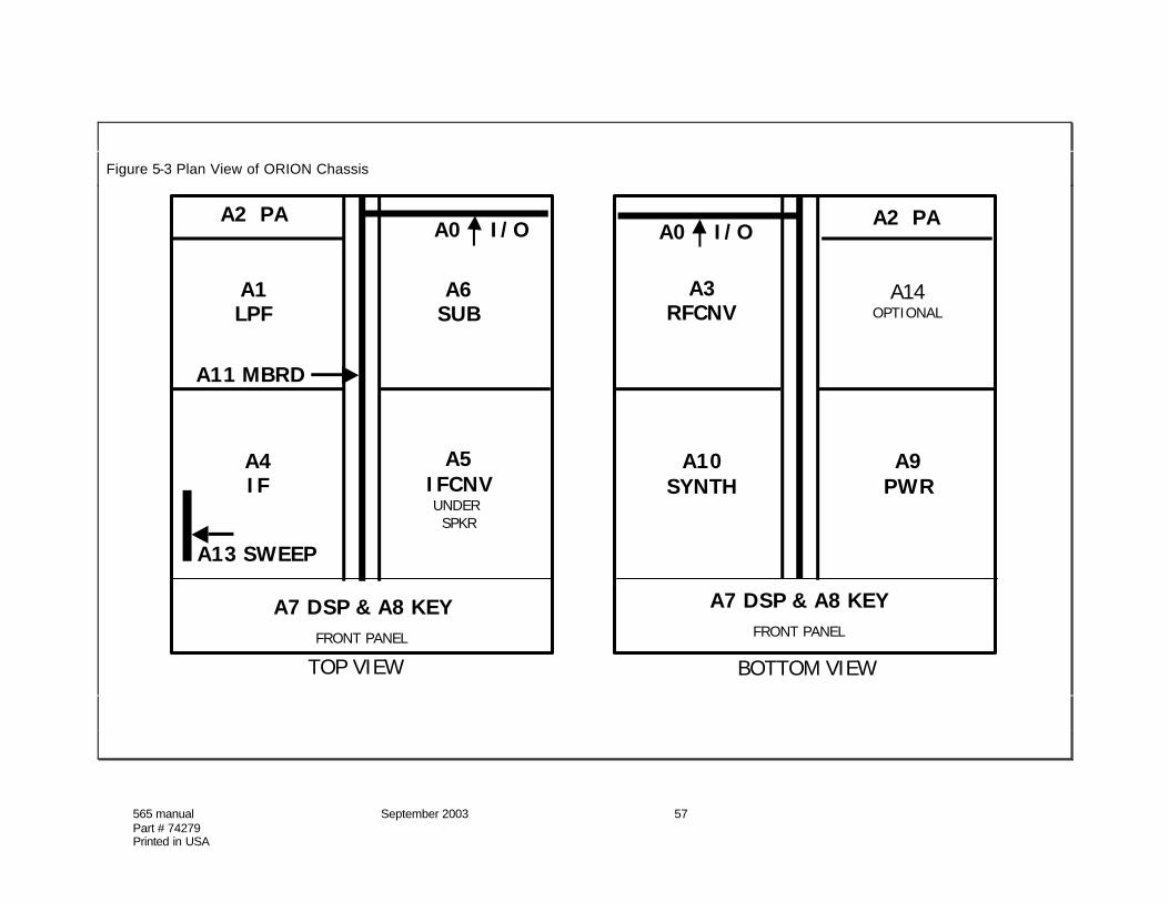
565 manual September 2003 57Part # 74279Printed in USA
Figure 5-3 Plan View of ORION Chassis
A1LPF
A4IF
A5IFCNVUNDER SPKR
A6SUB
A2 PA
A7 DSP & A8 KEYFRONT PANEL
A7 DSP & A8 KEYFRONT PANEL
A0 A0A2 PA
A10SYNTH
A9PWR
A3RFCNV
A14OPTIONAL
TOP VIEW BOTTOM VIEW
I/O I/O
A11 MBRD
A13 SWEEP

565 manual September 2003 58Part # 74279Printed in USA
Figure 5-4 Main Receiver Signal Path
A8KEYPADPWRDST
A9
A2PA
A1
LPF
A0 I/O
ANTENNAS(3), KEYING LOOPS(2), DC IN,FUSE, AMP KEYS(2), XVRT(2), BAND DATA(2)
REAR PANEL CONNECTORS:
A7
LOGIC
A6
SUBRX
A10
SYNTH
CONNA12
SERIAL DATA
SPKR, KEY,AUX I/O,REMOTE,
A14
AUTOTUNER
(Optional)A13 SWEEP
AMP 14B
A3RFCNV
A49MHZ IF
A5
IFCNV
11 1614A
WIRE CABLES
COAXIAL CABLES
2
12
1819
ENCODER 1
ENCODER 2
33 34
+12v
29
p/o A11
p/oA11
24 425 24 4 25

565 manual September 2003 59Part # 74279Printed in USA
Figure 5-5 Subreceiver Signal Path
A8KEYPADPWRDST
A9
A2PA
A1
LPF
A0 I/O
ANTENNAS(3), KEYING LOOPS(2), DC IN,FUSE, AMP KEYS(2), XVRT(2), BAND DATA(2)
REAR PANEL CONNECTORS:
A7
LOGIC
A6SUBRX
A10
SYNTH
24
20
CONNA12
SERIAL DATA
SPKR, KEY,AUX I/O,REMOTE,
244
A14
AUTOTUNER
(Optional)A13 SWEEP
AMP
A3RFCNV
A49MHZ IF
A5
IFCNV
WIRE CABLES
COAXIAL CABLES
1
21
234 25
25
ENCODER 1
ENCODER 2
33 34
p/o A11

565 manual September 2003 60Part # 74279Printed in USA
Figure 5-6 Transmit Signal Path
A8KEYPADPWRDST
A9
A2PA
A1
LPF8
7
9
A0 I/O
ANTENNAS(3), KEYING LOOPS(2), DC IN,FUSE, AMP KEYS(2), XVRT(2), BAND DATA(2)
REAR PANEL CONNECTORS:
LOGIC
A6SUBRX
A10
SYNTH
24
CONNA12
SERIAL DATA
SPKR, KEY,AUX I/O,REMOTE,
24
27
26 A13 SWEEPAMP
A3RFCNV
A49MHZ IF
A5
IFCNV
1315
A14
AUTOTUNER
(Optional)
WIRE CABLES
COAXIAL CABLES
3
17
6
10
1219
4 2525
ENCODER 1
ENCODER 2
33 3426 28
p/o A11 MBRD
A8KEYPADPWRDST
A9
A2PA
A1
LPF8
7
9
A0 I/O
ANTENNAS(3), KEYING LOOPS(2), DC IN,FUSE, AMP KEYS(2), XVRT(2), BAND DATA(2)
REAR PANEL CONNECTORS:
A7
LOGIC
A6SUBRX
A10
SYNTH
24
CONNA12
SERIAL DATA
SPKR, KEY,AUX I/O,REMOTE,
244
27
26 A13 SWEEPAMP
A3RFCNV
A49MHZ IF
A5
IFCNV
1315
A14
AUTOTUNER
(Optional)
WIRE CABLES
COAXIAL CABLES
1
3
17
6
10
1219
4 2525
ENCODER 1
ENCODER 2
33 3426 28
p/o A11 MBRD

Figure 5-7 Major ORION Cables
Ass'y From Function & ToName Direction Type Name Assy ID #
A0 I/O Sub Rx Ant In RG174 Sub Rx A6 1Main Rx Ant In RG174 Main Rx A3 2
XVERT Out RG174 Main Rx A3 3Main Rx Audio Out RG174 DSP/CPU A7 4
Tx RFOut RG174 Lowpass A2 5A2 PA PA Temp Out 2-3 Term I/O A0 6
PA RF Out RG188 Lowpass A2 7PA RF In RG174 Main RX A3 8
T-voltage Out 2-Term Lowpass A2 913.8 V In #16 Red I/O A0 10
A3 Main Rx 1st Rx IF Out RG174 9 MHx IF A4 111st LO In RG174 Synth A10 12
1st Tx IF In RG174 9 MHx IF A4 13A4 9 MHz IF IF to Sweep Amp RG174 Sweep Amp A13 14
Main Sweep In RG174 Sweep Amp A13 14A1st IF Out RG174 IF Converter A5 15
A5 IF Conv 3rd Tx IF In RG174 DSP/CPU A7 173rd Rx IF Out RG174 DSP/CPU A7 18
Main RX LO Ref RG174 Synth A10 19A6 Sub Rx Sub Rx 3rd IF Out RG174 DSP/CPU A7 20
Sub 1st LO Ref RG174 Synth A10 21Sub 2nd LO Ref RG174 Synth A10 23
A7 DSP/CPU Aux Audio In RG174 Conn A12 24Mic Audio RG174 Key Pad A8 25
Power Switch 2-Term Pwr Sw 30S-Meter 4-Term S-Meter 31
CCFL Backlight 2-Term CCFL 1-Wht-A 322-Blk-K
A8 Keypad Encoder 1 Out 5-Term Enc1 33Encoder 2 Out 5-Term Enc2 34
A9 Pwr Dist 5V DC 2-3-Term Dsp/CPU A7 35A11 Motherboard: PWB
Power & Control PWBA12 Conn Speaker 2-Term SpeakerA14 Tuner Tuner RF In RG188 I/O A0 26
Tuner RF Out RG188 I/O A0 27No-Tuner Jumper RG188 I/O A0 28
Schematic Diagrams
ORION’s schematic diagrams are available as Adobe™ .pdf files on the company firmwareupdate site located at www.rfsquared.com