chapter 1 sense: a sensor network simulator · sense: a sensor network simulator 3 1. design...
TRANSCRIPT

Chapter 1
SENSE: A SENSOR NETWORK SIMULATOR
Gilbert Chen, Joel Branch, Michael J. Pflug, Lijuan Zhu, and BoleslawK. SzymanskiDepartment of Computer Science,Rensselaer Polytechnic Institute
Abstract
A new network simulator, called SENSE, has been developed for
simulating wireless sensor networks. The primary design goal is to ad-
dress such factors as extensibility, reusability, and scalability, and to
take into account the needs of different users. The recent progresses
in component-based simulation, namely the component-port model and
the simulation component classification, provided a sound theoretical
foundation for the simulator. Practical issues, such as efficient mem-
ory usage, sensor network specific models, were also considered. Con-
sequently, SENSE becomes an ease-of-use and efficient simulator for
sensor network research.
Keywords: Wireless Sensor Networks, Network Simulation, Component-Based Sim-
ulation
Introduction
The emergence of wireless sensor networks created many open issuesin network design [Akyildiz et al., 2002]. The three main traditionaltechniques for analyzing the performance of wired and wireless networkswere analytical methods, computer simulation, and physical measure-ment. However, many constraints imposed on sensor networks, such asenergy limitation, decentralized collaboration, and fault tolerance ne-cessitate the use of complex algorithms for sensor networks that usuallydefy analytical methods. Furthermore, few sensor networks have comeinto existence, for there are still many unresolved research, design andimplementation problems, so measurements are virtually impossible. It

2
appears that simulation is currently the primary feasible approach tothe quantitative analysis of sensor networks.
ns2 (http://www.isi.edu/nsnam/ns/), perhaps the most widely usednetwork simulator for research, has been extended to include some basicfacilities to simulate sensor networks. However, one of the problems ofns2 is its object-oriented design that introduces much unnecessary inter-dependence between modules. Such interdependence sometimes makesthe addition of new protocol models extremely difficult, which can onlybe mastered by those who have intimate familiarity with the simulator.The difficulties in extension are not a major problem for simulators tar-geted at traditional networks, for there the set of popular protocols isrelatively small. For example, Ethernet is widely used for wired LAN,IEEE 802.11 for wireless LAN, TCP for reliable transmission over unre-liable channels, etc. For sensor networks, however, the situation is quitedifferent. There are no such dominant protocols or algorithms and therewill unlikely be any soon. A sensor network is often tailored to a par-ticular application with specific features, so it is unlikely that a singlealgorithm can always be the optimal one under various circumstances.
Many other publicly available network simulators, such as J-Sim [Houet al., ], SSFNet (http://www.ssfnet.org), Glomosim [Xiang Zeng, 1998]and its commercial descendant Qualnet, attempted to address problemsthat were left unsolved by ns2. Among them, J-Sim developers realizedthe drawback of object-oriented design and tried to attack this problemby inventing a component-oriented architecture. However, they choseJava as the simulation language, inevitably sacrificing the efficiency ofsimulation. SSFNet and Glomosim focus on parallel simulation, withthe latter tailored specifically to wireless networks. They do not appearsuperior to ns2 in the respects of design and extensibility.
SENSE (SEnsor Network Simulator and Emulator) aims to be an effi-cient and powerful sensor network simulator that is also easy to use. Weidentify three most critical factors in its design as extensibility, reusabil-ity, and scalability. We distinguish also three types of users as high-levelusers, network builders, and component designers. In the next section,we explain what each factor implies and how SENSE meets the differ-ent needs of all users. In the sections that follow, we present in detailsthe design decisions and implementation that are centered around thesedesign factors and that take full consideration of needs of all three typesof users. Finally, we will compare the performance of SENSE with thatof NS using the flooding simulation as a benchmark.

SENSE: A Sensor Network Simulator 3
1. Design Philosophy
1.1 Extensibility, Reusability and Scalability
The enabling force behind the fully extensible network simulation ar-chitecture in SENSE is the recent progress in component-based simula-tion [Szymanski and Chen, 2002]. A component-port model frees simu-lation models from interdependence usually found in an object-orientedarchitecture, and a simulation component classification naturally solvesthe problem of handling simulated time. The component-port modelmakes simulation models extensible: a new component can replace an oldone if they have compatible interfaces, and inheritance is not required.The simulation component classification makes simulation engines ex-tensible: advanced users have an option of developing new simulationengines that meet their special needs.
The removal of interdependence between models also promotes reusabil-ity. A component developed for one simulation can be used in anotherif it satisfies the latter’s requirements on the interface and semantics. InSENSE, another form of reusability is made possible by the extensiveuse of C++ template. A SENSE component is usually declared as atemplate class so that it can handle different types of data, dependingon the type parameters used to instantiate the component.
Unlike many other parallel network simulators, especially SSFNet(http://www.ssfnet.org) and Glomosim [Xiang Zeng, 1998], paralleliza-tion will be provided as an option to the users of SENSE. This decisionwas based on our belief that completely automated parallelization ofsequential discrete event models, however tempting it may seem, is im-possible. Even if it were possible, it would be doomed to be inefficient ascompared to hand-tuned parallel code. Therefore, parallelizable modelsmust require much more effort and time than sequential models, whilemany users are not interested in parallel simulation at all. In SENSE, aparallel simulation engine will be capable of executing an assemblage ofcompatible components. If a user is content with the default sequentialsimulation engine, then every component in the model repository can bereused.
1.2 High-Level Users, Network Builders andComponents Designers
High-level users solely rely on the model repository and network tem-plate library from where they can retrieve various network models andconfigurations to construct a sensor network simulation. For them, theprocess of building a simulation merely consists of selecting appropri-

4
ate models and templates and perhaps changing some parameters. Suchusers may not need any programming skills. Extensibility and reusabil-ity are not their concerns, but they may want the simulations to bescalable.
The network builders are not satisfied with the available network tem-plates, but they still rely on the model repository to obtain networkmodels. They may need to create new network topologies and trafficpatterns. These users may not have immediate or knowledge of popularprogramming languages, such as c/c++, Java. Extensibility is not anissue for them, since they are not interested in modifying the existingmodels. However, models must be reusable so that they can be pluggedinto many simulations.
The component designer often intend to modify available models oreven build new ones from scratch. For example, they can develop aproprietary MAC layer protocol which replaces the standard one. Theirmain concern is the extensibility; how easily existing models can beextended or replaced determines the willingness of these users to usethe simulator. Reusability may or may not be an issue, depending onwhether the new model is intended to be used in other simulations. Thebiggest challenge of the design for these users is to make the modelingprocess smoother, faster, and more reliable. The simulator should pro-vide facilities to speed up checking, debugging, and verification of themodels; there must be visualization tools to help identify any problemsquickly; there must be standards that these users can follow in order forthe models to be more accessible by others.
2. Component-Based Design
SENSE is built on top of COST [Chen and Szymanski, 2002], a generalpurpose discrete event simulator. The design of COST was largely influ-enced by the new understandings of both component-based software ar-chitecture and component-based simulation. Specifically, a component-port model was proposed to allow complex software systems to be builtas a composition of components. Later, it was extended to the sim-ulation domain where components are categorized into different types,based on how simulated time is dealt with.
2.1 Component-Port Model
In the component-port model, a component communicates with othersonly via inports and outports. An inport implements a certain function-ality, so it is similar to a function. In contrast, an outport serves as

SENSE: A Sensor Network Simulator 5
an abstraction of a function pointer: it defines what a functionality itexpects of others.
The fundamental difference between an object and a component inthe component-port model is that the interactions of a component withothers can be fully captured by the interface, while this is not the case foran object. For instance, an object is allowed to call member functions ofany other object if it keeps a pointer or a reference to that object. Suchcommunication, however, is not reflected in the interface or declarationof the object, and becomes manifest only when the implementation codeis being examined. The resulting problem is that any function call toexternal objects will introduce implicit interdependence between objects,preventing the object from being reusable.
The existence of outports distinguishes components from objects. Out-ports impose constraints on the dynamic runtime interaction betweencomponents. The important consequence of their existence is that thedevelopment of a component can now be completely separated from theapplication context in which the component will be used, leading totruly reusable components. Besides, components become more extensi-ble, because there are fewer constraints on a component that providesthe desired functionality. For instance, in an object-oriented environ-ment, if an object A is to be replaced by another object B, object B hasto be derived from A. In the component-port model, this constraint is nolonger necessary. Any component providing the satisfied functionalitycan be used, regardless of its component type.
2.1.1 Implementing Components. The subsequent task forus is to implement the component-port model with C++, a programminglanguage that is usually regarded as object-oriented. Fortunately, wefound template-based techniques can be utilized to archive this goal,although there are certain limitations due to the object-oriented featuresof the language.
First, we declare an mfunctor class that represents function objects formember functions of class TypeII. TypeII is the main component class,and we will explain why it is so called later in this section. The mfunctorclass overrides the operator() function, so it can be called the same wayas a normal function. Since it keeps a pointer to the component, it canbe used to call the member function of any object derived from TypeII,if initialized correctly.
template <class T>
class mfunctor
{
public:

6
typedef void (TypeII::*funct_t)(T&);
mfunctor(TypeII* _obj, funct_t _f)
:obj(_obj),f(_f) {}
void operator() (T& t) { (obj->*f)(t); }
private:
TypeII* obj;
funct_t f;
};
The inport class is just a wrapper class that extends mfunctor so thatthe latter can be more conveniently initialized and invoked. To initializean inport, a pointer to the component and a member function must beprovided.
template <class T>
class inport
{
public:
void Setup(TypeII * c, mfunctor<T>::funct_t f)
{
functor = new mfunctor<T>(c,f);
}
void Write(T& t) { (*functor)(t); }
private:
mfunctor<T> * functor;
};
The outport class maintains a pointer to the inport to which it is con-nected. The Connect() function can be called to initialize this pointer.When the Write() function of outport is called, the Write() function ofinport will be called, which in turn will invoke the member function ofthe component that was used to initialize the inport.
template <class T>
class outport
{
public:
void Connect(inport<T>&_in) { in=&_in;}
void Write(T& t) { in->Write(t); }
private:
inport<T>* in;
};
One drawback of implementing components as stated above is that theinter-component communication may become quite costly, as the C++

SENSE: A Sensor Network Simulator 7
compiler cannot completely optimize away the overhead of these func-tion calls. However, it is possible to develop an optimization techniquewhich can eliminate such communication overhead by merging compo-nents together so that the function to be called can be directly embeddedinto the code that makes the call, much the same as how inline functionswork.
Another problem with the above implementation is that member func-tions are limited to take only one argument, as in standard C++ tem-plate classes with different numbers of template parameters cannot begiven the same name. This problem can be solved by the use of wrap-per classes around several arguments to make them appear as a singleargument.
2.1.2 Components for Sensor Network Simulation. Thecomponent-port model gives the users a great deal of freedom in con-figuring sensor nodes. Figure 1.1 shows the internals of a typical sensornode. The sensor node is a composite component. It consists of anumber of smaller primitive components, each implementing a certainfunctionality. Normally a sensor node has some layered network proto-col components, a power component and a battery component both ofwhich are related to power management, and others such as mobilityand sensor. The inports and outports of the sensor node component aredirectly connected to the corresponding inports and outports of internalcomponents.
This structure, however, is by no means the only one that users muststrictly follow when they are building their own nodes. The user canfreely remove or add a component, as demanded by the particular goalof the simulation. For instance, the network protocol stack can be eithersimplified by removing the net component, or tuned up by adding anew transport layer without affecting any other components. A queuecomponent can be easily added between the network layer and the maclayer to prevent packets from being dropped when the mac layer is busytransmitting other packets.
In theory many programming languages can be used to configure sen-sor nodes into a network. Configuration is as simple as setting the pa-rameters of all components and then interconnecting their inports andoutports. In this phase, components do not communicate with eachother, so any object-oriented language is sufficient to perform the task.Currently, C++ is chosen to be the only configuration language, since itis also the implementation language for components. The simplicity ofthe configuration does allow such languages as TCL or XML to be used.

8
net
app
mac
mobility
to_channel from_channel pos_out
sensorSensor Node
data_in
battery
power phy
Figure 1.1. The internal structure of a typical sensor node
In addition, it is quite natural to develop a simple scripting languagespecifically for the network configuration phase.
2.2 Simulation Component Classification
The component-port model clarifies the role of components in the de-velopment of general software systems. It still remains unknown, how-ever, how the component-port model can be applied to simulation. Theanswer lies in a simulation component classification that naturally ex-tends the component-port model to the simulation domain [Szymanskiand Chen, 2002].
According to this classification, based on the way how simulated timeis handled, simulation components are grouped into time-independent,time-aware and autonomous classes, also named Type I, Type II andType III classes, respectively.
A Type I component does not have the notion of simulated time. Itis passive, as it never generates events without first having received anevent. A Type I component, when processing an event received fromother components, may generate new events that are required to havethe same timestamp as the incoming event that triggered it. Yet, thecomponent itself is unaware of the time semantics. Neither does it knowwhether it is running as a part of a simulation program or a part of a non-simulation program. For this reason, a time-independent component issaid to be time-unaware.
In contrast, Type II components are time-aware components. Theycannot advance the simulated time themselves, but they can make a timeadvance request via a special object called a timer. Timers provide amechanism for Type II components to generate events whose timestampis greater than the current simulated time. To schedule such a future
SENSE: A Sensor Network Simulator 9
event, a timer is set with a time increment representing the differencebetween the current simulated time and the timestamp of the futureevent. As soon as the specified simulated time increment elapses, thecomponent where the timer resides will be notified and then forced toprocess the activated event.
Type III components are named autonomous components becausethey maintain their own simulation clock themselves. A clock indicatesthe simulated time throughout the simulation. A sequential simulation isa Type III component by itself, which does not communicate with otherType III components. In parallel simulation, there are usually severalType III components, each mapping to a process or thread. These TypeIII components have to be synchronized by certain algorithms so thatthey can interact with each other correctly by exchanging events.
The simulation component classification leads to a hierarchical mod-eling process in SENSE. Because of the composability of components, anumber of components can be combined into a single component. How-ever, this kind of composition does not change the component type. Ifevery individual component is of Type I, so will the composite compo-nent. If at least one of them is of Type II, then the composite compo-nent will also be of Type II. A simulation engine changes the type of thecomponent. A simulation has to be a Type III component, so usuallybuilding a simulation involves deployment of one or several simulationengines.
This hierarchical modeling process distinguishes SENSE from manyother parallel network simulators. There, the simulation engines are of-ten built-in, and therefore users are forced to use the simulation enginesprovided by the simulator designers. Advanced SENSE users are giventhe option of building their own simulation engines, as the particularapplication they are investigating may call for a specific simulation algo-rithm (as of the time of this writing the parallelization of the simulatoris still in progress).
3. Packet Management
A network simulation is composed of two types of entities: one arethe static components that simulate various network devices and theother the dynamic packets that are created, transmitted, and receivedby components. The previous sections all dealt with only the simula-tion models, and we still need a good packet management scheme toeffectively manipulate the packets. It turns out that this is not a trivialproblem.
10
Our main consideration for the packet management is that it must bememory-efficient. Memory has become the most serious bottleneck thatprevents large simulation programs from running on computers equippedwith limited memory. Because of the extremely slow disk access speed,programs that rely on virtual memory are often an order of magnitudeslower than those that can fit into the physical memory. For this reason,we decided to design a packet management scheme that consumes aslittle memory as possible.
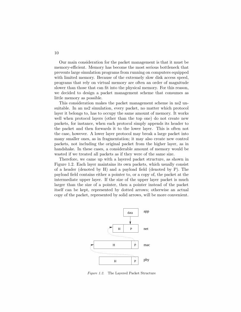
This consideration makes the packet management scheme in ns2 un-suitable. In an ns2 simulation, every packet, no matter which protocollayer it belongs to, has to occupy the same amount of memory. It workswell when protocol layers (other than the top one) do not create newpackets, for instance, when each protocol simply appends its header tothe packet and then forwards it to the lower layer. This is often notthe case, however. A lower layer protocol may break a large packet intomany smaller ones, as in fragmentation; it may also create new controlpackets, not including the original packet from the higher layer, as inhandshake. In these cases, a considerable amount of memory would bewasted if we treated all packets as if they were of the same size.
Therefore, we came up with a layered packet structure, as shown inFigure 1.2. Each layer maintains its own packets, which usually consistof a header (denoted by H) and a payload field (denoted by P). Thepayload field contains either a pointer to, or a copy of, the packet at theintermediate upper layer. If the size of the upper layer packet is muchlarger than the size of a pointer, then a pointer instead of the packetitself can be kept, represented by dotted arrows; otherwise an actualcopy of the packet, represented by solid arrows, will be more convenient.
app
net
mac
phy
H
data
P
P
P
H
H
Figure 1.2. The Layered Packet Structure

SENSE: A Sensor Network Simulator 11
Another decision we made regarding the packet management is thata packet sent by one node will be shared by all receiving nodes. Thisis possible because it is usually meaningless to ‘modify’ the receivingpacket. Wireless nodes always share the communication medium withneighbors, so it is expected that one packet will often be received bymany nodes. Consequently, the amount of memory saved by this ap-proach will be considerable.
A standard programming technique, reference counting, is adopted tokeep track of packets. When a node receives a packet, it must incrementthe reference count of the packet to indicate that it now partly ownsthe packet. When a packet is to be released, its reference count will bedecremented. Only when the reference count goes to zero can the packetbe actually deleted.
However, such a packet structure results in an inevitable problem.Assume a scenario in which a certain layer asks the physical layer totransmit a packet by pointer. The physical layer may successfully trans-mit the packet out, in which case the pointer will be forwarded to othernode. However, the problem arises when the transmission fails, for in-stance, if there are no other nodes within the transmission range. Thepacket has to be destroyed by the physical layer.
This implies that the lower layer may need to be responsible for releas-ing the pointer to the packet sent from any higher layer, and this problemis not limited to the physical layer, since other layers may attempt todrop packets under special circumstances. In general, no reliable trans-mission can be guaranteed.
On the other hand, if the payload field contains not the pointer to, buta copy of the packet from the upper layer, then no operation is neededwhen the packet is to be dropped. For any intermediate layer, packetsfrom the higher layer could be in the form of either pointers or plainstructures. It seems that we would have to implement two componentsfor each layer, one accepting pointers and the other copies.
Fortunately, this problem can be elegantly solved by a C++ templatetechnique referred to as trait. According to Bjarne Stroustrup, a traitis “a small policy object typically used to describe aspects of a type”(http://www.research.att.com/ bs/glossary.html). In SENSE, a specialpacket trait class is declared which can tell if a certain template param-eter is a packet structure or a packet pointer.
The declaration of this packet trait class is shown below. Basically itmeans that for general packets, nothing needs to be done with regard topacket deallocation.
template <class T>
class packet_trait

12
{
public:
static void free(const T&) {};
};
The smart packet t class is the main SENSE packet class defined forlayers other than the top one. It consists of a header and a payload field,as well as a reference count.
template <class H, class P>
class smart_packet_t
{
public:
...
inline void free();
H hdr;
P pld;
private:
int refcount;
};
In the free() function of the smart packet t class, it first calls the free()function of the payload via the packet trait class. It then decrements thereference count, and if the reference count is zero, both the header anditself will be freed.
template <class H, class P>
void smart_packet_t<H,P>::free()
{
packet_trait<P>::free(pld);
refcount--;
if(refcount==0)
{
packet_trait<H>::free(hdr);
delete this;
}
}
Below is the partial specialization of packet trait for pointers to smart packet t.As a result, in the free() function given above, if the payload contains apointer to a smart packet, the smart packet will be freed; for all othercases nothing happens. If users are to define their own packet types andkeep track of them by pointers, they should specialize the packet traitclass in a similar way.

SENSE: A Sensor Network Simulator 13
template <class H, class P>
class packet_trait< smart_packet_t<H,P>* >
{
public:
typedef smart_packet_t<H,P> nonpointer_t;
static void free(nonpointer_t* const &p)
{
if(p!=NULL) p->free();
}
};
4. Component Repository
As the core design of SENSE has been finalized, we built an exten-sive set of components ranging from application layer to physical layer,as well as energy and mobility models that are specifically targeted atsensor networks.
4.1 IEEE 802.11
The IEEE 802.11 component in SENSE implemented the distributedcoordination function (DCF) described in the IEEE 802.11 standard. Totransmit a data packet, this MAC component first checks the size of thedata packet. If the size is smaller than a predefined threshold given bya parameter named RTSThreshold, or if the data packet is to be broad-cast, the data packet will be transmitted directly, with a proper headeradded. If the size is greater than RTSThreshold, an RTS/CTS exchangemechanism will be invoked prior to the actual data transmission, in or-der to reserve the medium for a period of time that is just sufficient forthe entire transmission. A unicast data packet must be accompanied byan acknowledgment, but not a broadcast data packet. A transmission isdeemed successful only if the acknowledgment packet has been correctlyreceived. Each failed transmission will double the content window untilit reaches the preset maximum value.
The IEEE 802.11 implementation in SENSE has the same detail levelas that of ns2 (http://www.isi.edu/nsnam/ns/). However, the sourcecode in SENSE is twice as short as that in ns2, which can be attributedto the simplicity and effectiveness of the SENSE API. For example,timers are implemented as a template class that takes the type of eventas a parameter. Defining a timer in SENSE is as simple as writing astatement to instantiate the timer. On the contrary, in ns2 each timerinstance needs a unique implementation of a class derived from the basetimer class, which greatly degrades the efficiency and readability.

14
4.2 AODV
Ad-hoc on demand distance vector routing (AODV) has been well-received as a routing protocol for wireless networks. AODV’s routediscovery consists of setting up a forward and reverse data transmis-sion path between two mobile nodes. After route discovery is complete,each node belonging to the established path maintains a routing tablevia sequenced requests and response messages. A table entry primarilyconsists of two IDs: one denoting the destination node and the otherdenoting the next-hop node along the path to the destination. The se-quence numbers included in the request/response packets ensure thatthese routes are loop-free. Other table entry information is used tomaintain route freshness, so that outdated route entries may be prop-erly replaced. AODV’s route maintenance also provides facilities forreplacing damaged routes (e.g., those with broken links). Each nodemaintains only partial (local) route information, so full path informa-tion is never transmitted between nodes. A seminal document [Perkins,1997] provides more details about AODV.
The AODV implementation in SENSE is based on the most currentAODV internet draft [Perkins et al., 2003]. We have implemented theoperative components essential to AODV’s basic operation. This set in-cludes all steps required to actually build routes. However, selected routemaintenance functions have not been included in the current simulation.For example, provisions noted in section 6.8 of [Perkins et al., 2003] forhandling of unidirectional links have not been implemented. This isprimarily because we only assume bi-directional links in our simulation.We have not yet included full facilities for maintaining local connectivity,processing route error packets, or implementing local repair functions.All these are expected to be completed in the near future.
4.3 DSR
Dynamic Source Routing (DSR) [Johnson et al., 2001] is anotherwidely used on-demand routing protocol for wireless networks. Simi-lar to AODV, DSR provides a mechanism of route discovery if the routefrom the source to the destination is unknown. But unlike AODV, afterthe route has been discovered, the entire route is included in the packetheader, and intermediate nodes will determine the next hop by lookingat the routing information contained in the packet.
An initial version of the DSR Component for SENSE has been com-pleted which makes certain restrictive assumptions within DSR specifi-cations. Specifically, all nodes are assumed to be bi-directional, withoutsupport for promiscuous communications, and running in a homoge-

SENSE: A Sensor Network Simulator 15
neous link layer environment. Moreover, we assume that all communi-cation links, once established, are not subject to damages, and henceerror handling and route recovery are not necessary. Our testing en-vironment currently consists of DSR running on top of the 802.11 linklevel component, for which all of these assumptions are valid.
As DSR matures, and new upper-level and lower-level networkingcomponents are created, a number of the current limitations will beremoved. An Immediate plan is to include route error packets so thatthe network can recover from faulty nodes or communication obstacles.Other plans include support for the promiscuous mode operation, theoptional DSR flow state extension, uni-directional links, and a data linklayer which does not provide acknowledgment information for unicastpackets.
4.4 Battery Models
Two battery components have been implemented in SENSE. In theSimpleBattery component, the discharge rate is always proportional tothe power drawn from the battery, and is not dependent on the current.Its capacity is a constant defined by the simulation parameter. Let E′
be the previous remaining energy and P the power consumed in thetime unit, the energy remaining after a consumption period of t can beexpressed as:
E = E′− Pt (1.1)
In the more complex RealBattery component, the discharge rate be-comes dependent on the current: larger current usually renders the bat-tery discharge quicker, thus resulting in less actual capacity at the endof the usage period than the smaller current would do [Park et al., 2001].A discharge rate dependence parameter, k, determines how the value ofthe current affects the discharge rate. More specifically, Equation 1.1becomes:
E =E′
1 + kI− Pt (1.2)
The RealBattery component also models relaxation [Park et al., 2001],which refers to the phenomenon that a battery may gradually recoversome of its lost capacity if the discharge current undergoes a suddendrop to become very small. For simplicity, we assume that relaxationonly occurs if the current first sustains for a fast discharge period of atleast TR with a current larger than IR, and then suddenly drops from

16
above IR to 0. Let λ be the recovery rate, g the growth ratio that canbe eventually reached, then during the relaxation period the capacity isgoverned by the following equation:
E = gE′(1 − e−λt) (1.3)
A restriction is imposed to ensure that the capacity after the relax-ation period would not exceed the capacity right before the fast dischargeperiod.
In this component, another parameter is provided to turn the relax-ation off. If there is not relaxation, and if k, the discharge rate depen-dence parameter, is zero, the component regresses to the SimpleBatterycomponent.
4.5 Power Model
In SENSE, the power component is responsible for power manage-ment. Currently, a SimplePower component has been implemented,which can operate on any of 5 modes: TRANSMIT, RECEIVE, IDLE,SLEEP, and OFF. 4 parameters specify the energy consumption rateunder each of the first 4 modes, while in the OFF mode there is noenergy consumption.
The power component accepts control from networking components.In response to the control signal, it can switch from one mode to another.Depending on its operating mode it also draws corresponding currentfrom the battery.
5. Performance Comparison
To test the performance of SENSE in terms of execution speed andmemory efficiency, we carried out a set of experiments that comparedSENSE with ns2.
All simulations were conducted using a Dell Latitude D600 with anIntel 1.6 Ghz Pentium-M processor and 512MB 266MHz DDR SDRAM.The flooding simulation was used as the benchmark for comparison.The flooding implementation in the ns2 distribution was modified tominimize the memory usage. In the original implementation, each nodemaintained a hash table that stored every packet that has been received.After the modification was applied, each node would only store the lat-est sequence number for each source. Any packet that comes from asource with a sequence number smaller than the latest sequence numberknown for this source is deemed as having been received before. Thismodification greatly reduced memory consumption, and is in accordancewith the flooding implementation in SENSE.

SENSE: A Sensor Network Simulator 17
0
200000
400000
600000
800000
1e+06
1.2e+06
1.4e+06
0 5000 10000 15000 20000 25000 30000 35000
Eve
nt P
roce
ssin
g R
ate
(eve
nts/
sec)
Simulation Time (seconds)
NSSENSE
Figure 1.3. Event Processing Rate of NS and SENSE
For the comparison, TCL and C++ scripts were written to randomlygenerate traffic and topology files, and both simulators were modified toread from the same input files. All nodes are running the IEEE 802.11protocol, but using only the broadcast functionality due to the natureof flooding. Simulations were conducted to compare the two simulatorsexecution times and memory usage under various conditions.
All NS-2 simulations were conducted using NS-2 version 2.26. A fewchanges were made to the flooding TCL script that comes with the ns2distribution to disable the simulator from producing the trace file. Theheap scheduler was used in both, because it is less sensitive to differenttime increment distributions. Unnecessary headers were also removedto minimize the size of each packet.
We compared the execution speeds of both simulators. We createda wireless sensor network containing 60 nodes, with the same randomplacement and a 1000m by 1000m terrain. 12 sources were randomlychosen to send packets with a length of 1000 bytes, at fixed intervals of10 seconds. Figure 1.3 shows that SENSE is consistently twice as fastas ns2. In both simulators the number of events were roughly the same.
The dramatic performance difference between ns2 and SENSE can belargely attributed to the ways they allocate and release packets. In ns2,when a packet is being broadcast, every neighboring node will receivea copy, so the number of packet allocations is equal to the number ofreceived packets. In SENSE, a packet is always shared by all receivers, sothe number of packet allocations is equal to the number of sent packets.In a dense wireless network, a node can usually communicate with dozensof neighbors. Consequently the number of received packets is far greaterthan the number of sent packets. Figure 1.4 confirms this explanation.

18
10000
100000
1e+06
1e+07
1e+08
1e+09
0 5000 10000 15000 20000 25000 30000 35000
Num
ber
of P
acke
t Allo
catio
ns in
the
MA
C la
yer
Simulation Time (seconds)
NSSENSE
Figure 1.4. Frequency of Packet Allocation in ns2 and SENSE
6. Related Work
As stated in the introduction section, the development of SENSEwas largely motivated by the realization of the fundamental drawbackin the object-oriented designed of ns2 (http://www.isi.edu/nsnam/ns/).Compared with ns2, SENSE is not only more efficient, as shown by lastsection, but also more advanced in the architecture design since SENSEgreatly promotes the reusability and composability of network models.
J-Sim [Hou et al., ] is also claimed to be a wireless network sim-ulation with a component- oriented architecture. However, the inter-communication efficiency was not taken as a principal design factor, andas a result the overhead is larger than in the current version of SENSE.More specifically, in every J-Sim component, a process() function handlesincoming events for all ports, which involves dynamic dispatch of eventsbased on the ports that they come from. However, this mechanism in-curs unnecessary run-time overhead, since communication between com-ponents can be largely deduced statically from their connections.
Several other simulators devoted to wireless sensor networks have beenin progress. Among them, TOSSIM [Levis et al., 2003] and Emstar [Girod et al., 2004] are similar to each other in that both are a combina-tion of a simulator and an emulator that can facilitate the developmentand deployment of sensor nodes. SensorSim [S. Park and Srivastava,2000] is basically a sensor network extension of ns2, while SensorSimII [Ulmer, ] has been rewritten in Java but still inherited the object-orienteddesign. SENS [Sundresh et al., 2004], being developed at UIUC, is an-other object-oriented sensor network simulator.
SENSE: A Sensor Network Simulator 19
7. Conclusion and Future Work
The most significant feature of SENSE is its balanced consideration ofmodeling methodology and simulation efficiency. In designing SENSE,we attempt to convey a belief that it is possible to build a very user-friendly simulator that is also very fast. Unlike object-oriented networksimulators, SENSE is based on a novel component-oriented simulationmethodology that promotes extensibility and reusability to the maxi-mum degree. At the same time, the simulation efficiency and the issueof scalability are not overlooked. We observed that memory is the majorfactor that limits the size of simulation that can be actually performed,and that many other simulators contain too much overhead with respectto memory usage. The simulator is therefore memory-efficient, fast, ex-tensible, and reusable.
SENSE is still in its active development phase. Although the coreof the simulator has been gradually stabilized, it still lacks a compre-hensive set of models and a wide variety of configuration templates forwireless sensor networks. Besides, a visualization tool is desirable whichcan quickly track down what goes wrong during the simulation. Withoutsuch a tool, the output of the simulation is hard to interpret. Visualiza-tion can also facilitate the configuration phase by allowing networks tobe constructed graphically.
The problem of inefficient inter-component communication can becompletely solved very soon. We have designed a component exten-sion to the C++ language. The new language extension introduces onlyfour keywords and four syntactic rules, with simple semantics that areeasy to understand. It will not only improve the simulation speed, butalso free SENSE users from the constraint that limits the number andgranularity of components that can be used when efficiency is the mainconcern, since the inter-component communication overhead will be en-tirely eliminated with this new language extension.


References
Akyildiz, I. F., Su, W., Sankarasubramaniam, Y., and Cyirci, E. (2002).Wireless sensor networks: A survey. Computer Networks, 38(4):393–422.
Chen, Gilbert and Szymanski, Boleslaw K. (2002). COST: Component-oriented simulation toolkit. In Proceedings of the 2002 Winter Simu-lation Conference.
Girod, L., Elson, J., Cerpa, A., Stathopoulos, T., Ramanathan, N., andEstrin, D. (2004). Emstar: a software environment for developing anddeploying wireless sensor networks. In the Proceedings of USENIXGeneral Track 2004.
Hou, Jennifer, ying Tyan, Hung, et al. J-sim. http://www.j-sim.org/.Johnson, D., Maltz, D., and Broch, J. (2001). Ad Hoc Networking, chap-
ter DSR The Dynamic Source Routing Protocol for Multihop WirelessAd Hoc Networks, pages 139–172. Addison-Wesley.
Levis, Philip, Lee, Nelson, Welsh, Matt, and Culler, David (2003). Tossim:Accurate and scalable simulation of entire tinyos applications. In Pro-ceedings of the First ACM Conference on Embedded Networked SensorSystems.
Park, Sung, Savvides, Andreas, and Srivastava, Mani (2001). Batterycapacity measurement and analysis using lithium coin cell battery.In Proceedings of the 2001 international symposium on Low powerelectronics and design, pages 382–387. ACM Press.
Perkins, C. (1997). Ad hoc on demand distance vector (AODV) routing.Perkins, C., Belding-Royer, E., and Das, S. (2003). Rfc 3561 - ad hoc
on-demand distance vector (AODV) routing.S. Park, A. Savvides and Srivastava, M. B. (2000). Sensorsim : A simu-
lation framework for sensor networks. In the Proceedings of MSWiM2000.
Sundresh, Sameer, Kim, WooYoung, and Agha, Gul (2004). Sens: Asensor, environment and network simulator. In The 37th Annual Sim-ulation Symposium (ANSS37).
22
Szymanski, Boleslaw K. and Chen, Gilbert (2002). Lecture Notes inComputer Science, Parallel Processing and Applied Mathematics: 4thInternational Conference, chapter A Component Model for DiscreteEvent Simulation, pages 580–594. Springer-Verlag.
Ulmer, Craig. Wireless sensor probe networks - SensorSimII.http://www.craigulmer.com/research/sensorsimii/.
Xiang Zeng, Rajive Bagrodia, Mario Gerla (1998). Glomosim: a libraryfor parallel simulation of large-scale wireless networks. In Proceedingsof the 12th Workshop on Parallel and Distributed Simulations.