chapter 1 introduction: thesis aims and contents · 2) evaluate the ... outline potential...
TRANSCRIPT
Chapter 1 - Introduction 1
CHAPTER 1Introduction: Thesis aims and contents
1.1 Introduction
The Ladolam gold deposit, on Lihir Island, Papua New Guinea (Figs. 1.1, 1.2 and 1.3)
has been classifi ed by previous workers as a giant, low-sulfi dation epithermal gold deposit
(Carman, 1994). Mineralisation is associated with diverse breccia facies that include the
products of hydrothermal, volcanic and sedimentary processes. The central aim of this thesis
is to unravel the complexity of the breccias at Ladolam. This chapter introduces the fi eld
site, presents the thesis aims and their signifi cance, and provides a background discussion on
breccia terminology and approach used in this study.
This research project has focused on the character and origin of the host succession
to the Ladolam gold deposit, based on exposures and drill core from the Minifi e and Lienetz
ore zones. The lithofacies identifi ed in this study record the evolution of a host volcano-
sedimentary stratigraphy overprinted by hydrothermal facies. Hydrothermal facies record the
progression from porphyry to epithermal environments, as previously reported by Carman
(1994), and contain gold deposited in at least three distinct stages (Carman, 1994, 2003).
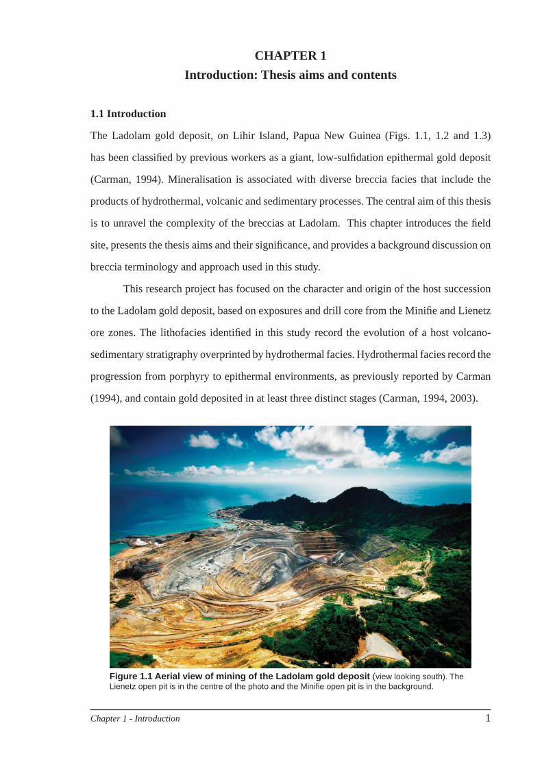
Figure 1.1 Aerial view of mining of the Ladolam gold deposit (view looking south). The Lienetz open pit is in the centre of the photo and the Minifi e open pit is in the background.
2 Chapter 1 - Introduction
1.2 Thesis aims and signifi cance
The principal aims of this thesis are to:
characterise the breccia facies at Ladolam, specifi cally, their textures, components, 1)
geometries, contact relationships and spatial context, and to interpret their
origins;
evaluate the spatial and temporal relationships between breccia facies and gold 2)
mineralisation;
defi ne the architecture of the host succession to the Ladolam gold deposit in the 3)
Minifi e and Lienetz ore zones;
reconstruct the geologic history of the host succession and the ore forming events 4)
of the Ladolam gold deposit based on the Minifi e and Lienetz ore zones, and
outline potential exploration implications.
In terms of contained gold, the Ladolam gold deposit is the world’s largest low-
sulfi dation epithermal deposit (Carman, 2003), but the controls on mineralisation remain
poorly understood. This research contributes to that understanding by characterising the
geologic setting and resolving relationships amongst various facies that host the gold deposit.
The host succession of the Ladolam gold deposit is geologically young and therefore provides
an analogue for older, less well preserved alkalic mineralised successions. As well, the
current tectonic confi guration of Lihir Island as part of the New Ireland Basin can be linked
to ore formation, and this information could be useful for alkalic epithermal ore deposit
exploration strategies.
Another signifi cant goal of this research has been to develop a systematic approach
to breccia description and classifi cation in volcanic-hydrothermal environments. Such
breccias have been widely documented by previous workers (e.g. Sillitoe, 1985; Taylor
and Pollard, 1993; Corbett and Leach, 1998; Browne and Lawless, 2001), but a standard
approach to description and interpretation has not been universally established. Careful
systematic description is a pre-requisite for further understanding of the processes of
fragmentation, transportation and deposition in volcanic-hydrothermal environments, as
well as understanding the relationships between breccias and mineralisation events.
Chapter 1 - Introduction 3
10 So
0 o
150 Eo
150 Eo
N
500 km
IND
ON
ES
IA
AUSTRALIA
SOLOMONISLANDS
PAPUA NEW GUINEA
Port Moresby
Manus Island
New Britain
Bougainville
NewIreland
Rabaul
Tabar
TangaFeni
Lihir
PacificOcean
BismarckSea
Coral Sea
Gulf ofPapua
Solomon Sea
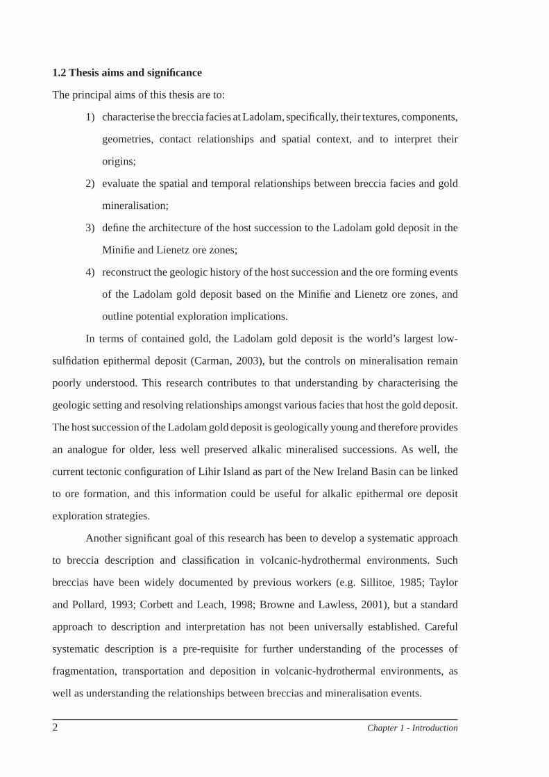
Figure 1.2 Map of Papua New Guinea and surrounding countries, showing the location of the Lihir Island group.
This research was conducted as part of a broader research project entitled “Shallow-
and deep-level alkalic mineral deposits: an integrated exploration model”. The ‘alkalic’ project
was a joint study between the Mineral Deposit Research Unit (MDRU) at the University
of British Columbia and CODES. This PhD study has helped to develop a holistic alkalic
mineral deposit model by unravelling both the deposit-scale and regional-scale geologic
setting of the Ladolam gold deposit.
1.3 Field site
The Lihir Island group is located ~900 km north-east of Port Moresby, (3°08”S, 152°38”E)
in the New Ireland Province of Papua New Guinea (Figs. 1.2 and 1.3). Niolam Island is
commonly referred to as Lihir and is the largest of fi ve islands that make up the Lihir Island
group (Mali, Mahur, Masehet, Sanambiet and Niolam). Lihir Island rises to 660 m above sea
level from more than 2000 m water depth. The temperature ranges from 19 to 35°C and the
4 Chapter 1 - Introduction
100
200
300
400
500600
Kunaiya
LGL Town site
Londolovit
Kapit
Putput No. 1
Putput No. 2
Libuko
School
Matakues
Kinami
Lataul
Lisel
TombavilLinmel
Komat
Palle Mission
Pango
Talis
WurtolSianus
Samo No. 2
Lagagot BayLakakot Passage
Lake Kenham Bay
Luise Harbour
Lamboa
Huniho
Banem
SaliLienbil
Suen
Gosmaium
153 o 00’
153 o 00’
152 o 00’
152 o 00’
151 o 00’
151 o 00’
3 o 00’ 3 o 00’
4o 00’
5 o 00’ 5 o 00’
New Britain
New Ireland
TabarIslands
LihirIslands
TangaIslands
FeniIslands
9,655,000 N9,660,000 N
9,665,000 N9,650,000 N
9,645,000 N
9,65
5,00
0 N
9,66
0,00
0 N
9,66
5,00
0 N
9,65
0,00
0 N
460,000 E
460,000 E 450,000 E
5 km2.50N
Ladolam Gold Deposit> 1 g/t Au
Roads
Villages
100 m togographic contours
Rivers
Wurtol
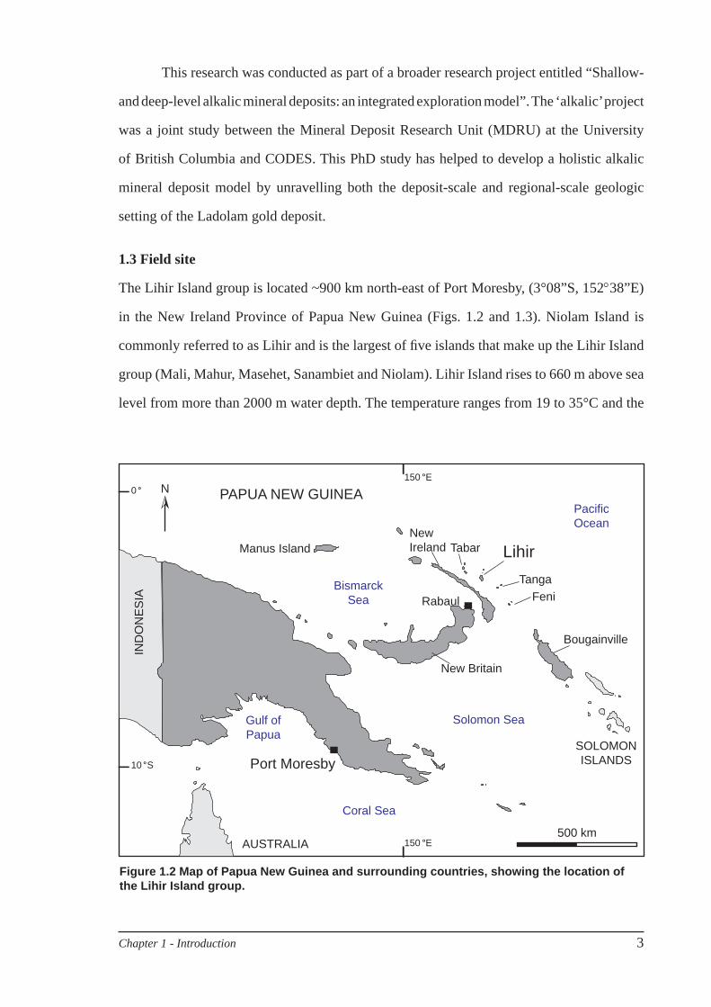
Figure 1.3 Location of the Ladolam gold deposit on Lihir Island, in the New Ireland Province of Papua New Guinea. Map Projection: Austalian UTM map grid, zone 56S. Contours, streams, roads and ore shells (> 1.5 g/t Au) from LGL database. Villages and geographic locations from the Lihir Sheet 9491, Papua New Guinea - Australian National Mapping Bureau, 1983.
Chapter 1 - Introduction 5
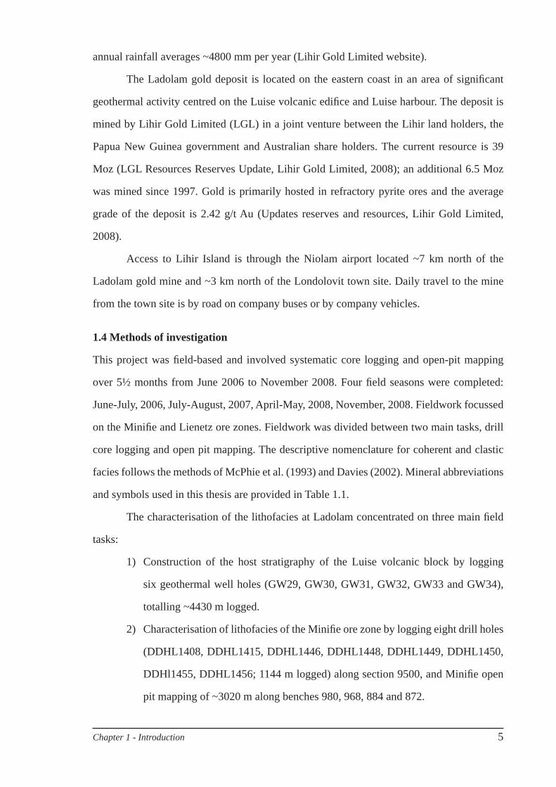
annual rainfall averages ~4800 mm per year (Lihir Gold Limited website).
The Ladolam gold deposit is located on the eastern coast in an area of signifi cant
geothermal activity centred on the Luise volcanic edifi ce and Luise harbour. The deposit is
mined by Lihir Gold Limited (LGL) in a joint venture between the Lihir land holders, the
Papua New Guinea government and Australian share holders. The current resource is 39
Moz (LGL Resources Reserves Update, Lihir Gold Limited, 2008); an additional 6.5 Moz
was mined since 1997. Gold is primarily hosted in refractory pyrite ores and the average
grade of the deposit is 2.42 g/t Au (Updates reserves and resources, Lihir Gold Limited,
2008).
Access to Lihir Island is through the Niolam airport located ~7 km north of the
Ladolam gold mine and ~3 km north of the Londolovit town site. Daily travel to the mine
from the town site is by road on company buses or by company vehicles.
1.4 Methods of investigation
This project was fi eld-based and involved systematic core logging and open-pit mapping
over 5½ months from June 2006 to November 2008. Four fi eld seasons were completed:
June-July, 2006, July-August, 2007, April-May, 2008, November, 2008. Fieldwork focussed
on the Minifi e and Lienetz ore zones. Fieldwork was divided between two main tasks, drill
core logging and open pit mapping. The descriptive nomenclature for coherent and clastic
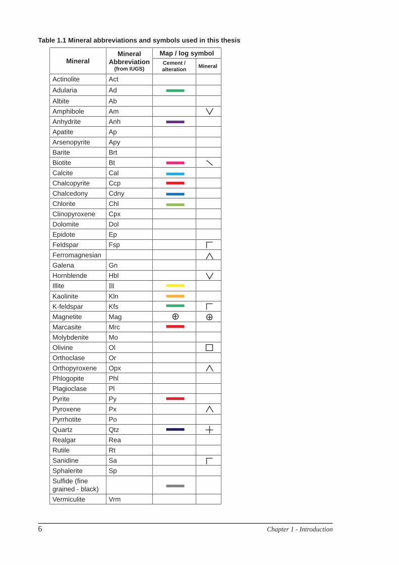
facies follows the methods of McPhie et al. (1993) and Davies (2002). Mineral abbreviations
and symbols used in this thesis are provided in Table 1.1.
The characterisation of the lithofacies at Ladolam concentrated on three main fi eld
tasks:
Construction of the host stratigraphy of the Luise volcanic block by logging 1)
six geothermal well holes (GW29, GW30, GW31, GW32, GW33 and GW34),
totalling ~4430 m logged.
Characterisation of lithofacies of the Minifi e ore zone by logging eight drill holes 2)
(DDHL1408, DDHL1415, DDHL1446, DDHL1448, DDHL1449, DDHL1450,
DDHl1455, DDHL1456; 1144 m logged) along section 9500, and Minifi e open
pit mapping of ~3020 m along benches 980, 968, 884 and 872.
6 Chapter 1 - Introduction
Mineral Mineral
Abbreviation(from IUGS)
Map / log symbolCement / alteration Mineral
Actinolite ActAdularia AdAlbite AbAmphibole AmAnhydrite AnhApatite ApArsenopyrite ApyBarite BrtBiotite BtCalcite CalChalcopyrite CcpChalcedony CdnyChlorite ChlClinopyroxene CpxDolomite DolEpidote EpFeldspar FspFerromagnesianGalena GnHornblende HblIllite IllKaolinite KlnK-feldspar KfsMagnetite MagMarcasite MrcMolybdenite MoOlivine OlOrthoclase OrOrthopyroxene OpxPhlogopite PhlPlagioclase PlPyrite PyPyroxene PxPyrrhotite PoQuartz QtzRealgar ReaRutile RtSanidine SaSphalerite SpSulfi de (fi ne grained - black)Vermiculite Vrm
Table 1.1 Mineral abbreviations and symbols used in this thesis
Chapter 1 - Introduction 7
Characterisation of lithofacies of the Lienetz ore zone by logging eight drill holes 3)
(DDHL712, DDHL757, DDHL791, DDHL1160, DDHL1476, DDHL1703,
DDHL1704 and DDHL1709; 1585 m logged), and Lienetz open pit mapping of
~3750 m from bench 992 down to bench 824.
1.4.1 Drill core logging methods
Over 2070 drill holes have been drilled into and surrounding the Ladolam ore body. Because
much of the archived core has been discarded or is too degraded to recognise lithology,
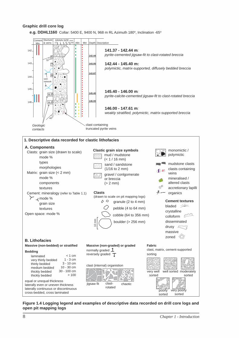
recently drilled core was selected for this study. Core was logged in detail at a 1:10 to 1:20
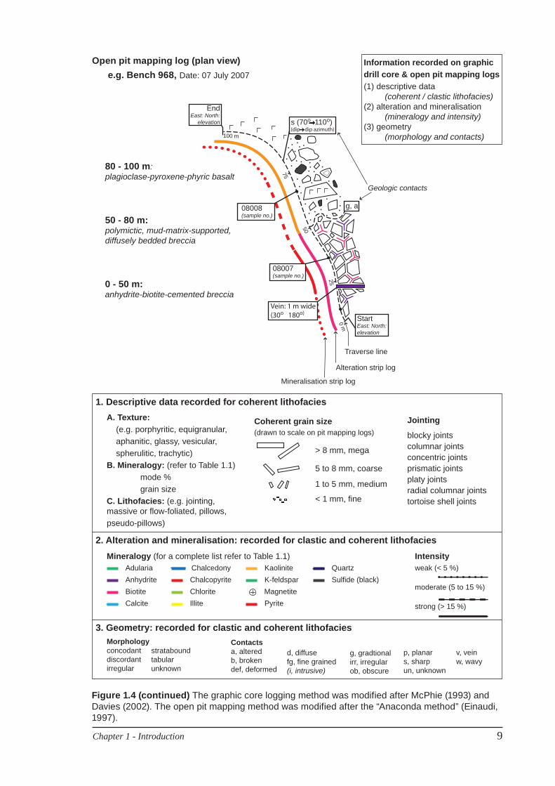
scale. The graphic logging method (Fig. 1.4; described in detail in McPhie et al., 1993;
Gifkins et al., 2005) was used for drill core, supplemented with an additional column for
cement mineralogy and texture. Drill holes logged as part of this study are provided digitally
in Appendix A.
1.4.2 Open pit mapping methods
The Lihir open pits have a unique set of obstacles presented by the active geothermal system.
Benches are mined at 12 m heights to allow the rocks to cool enough for safe mining practices.
Many areas, especially within the Lienetz pit, are classifi ed as “Potential Geothermal Outburst
Areas; PGOA’s” and entry is not permitted. Within these geothermal areas, the rocks are
hot (> 50°C) and there are geysers, fumaroles, unstable ground and pools of boiling water.
The areas of active mining provide the best exposure for pit mapping as the newly exposed
rock reacts quickly with rainfall and air to form a coating of jarosite that obscures primary
textures. Despite these complications, the pits offer excellent three dimensional exposures
of lithofacies that has aided tremendously in geologic interpretation. The pits were mapped
at 1:1000 scale using the “Anaconda” method (Einaudi, 1997) to produce a plan map. The
Anaconda method was adapted to record descriptive data (Fig. 1.4).
At the time of this study, the Minifi e ore zone had been mined to 872 m RL and since
2007, the area has been reclaimed as a low grade stockpile. Systematic mapping of Minifi e
benches throughout the 2006 fi eld season was permitted. Active mining of the Lienetz pit has
been ongoing throughout this PhD study. Opportunistic mapping (dictated by safety issues)
8 Chapter 1 - Introduction
Figure 1.4 Logging legend and examples of descriptive data recorded on drill core logs and open pit mapping logs
B. Lithofacies
A. Components
laminatedvery thinly beddedthinly beddedmedium beddedthickly beddedthickly bedded
Bedding< 1 cm
1 - 3 cm 3 - 10 cm
10 - 30 cm 30 - 100 cm
> 100
Massive (non-bedded) or stratified Massive (non-graded) or graded Fabric
equal or unequal thicknesslaterally even or uneven thicknesslaterally continuous or discontinuouscross-bedded, cross laminated
clast, matrix, cement-supportedsorting
clast (internal) organistion
normally gradedreversely graded
very well sorted
well sorted moderately sorted
poorly sorted
very poorly sorted
jigsaw fit clast-rotated
chaotic
mudstone clastsclasts containing veinsmineralised / altered clastsaccretionary lapilliorganics
Clastic grain size symbols
sand / sandstone(1/16 to 2 mm)gravel / conlgomerateor breccia(> 2 mm)
mud / mudstone(< 1 / 16 mm)
monomictic /polymictic
Cement texturesbladedcrystallinecolloformdisseminateddrusymassive zoned
10 m
m
granule (2 to 4 mm)
pebble (4 to 64 mm)
cobble (64 to 356 mm)
boulder (> 256 mm)
Clasts (drawn to scale on pit mapping logs)
1. Descriptive data recorded for clastic lithofacies
Clasts: grain size (drawn to scale) mode % types morphologies Matrix: grain size (< 2 mm) mode % components textures Cement: mineralogy (refer to Table 1.1) mode % grain size texturesOpen space: mode %
142
143
144
145
146
e.g. DDHL1160 Graphic drill core log
s
a
a,d
a,d
?
142.44
143.05
143.87
145.40
146.00
CementMin. MinAltn Depth Description
GRAIN SIZE (mm)Stucture& veins 1/16 2 8 32 64256
Collar: 5400 E, 9400 N, 968 m RL Azimuth 180o, Inclination -65o
141.37 - 142.44 m: pyrite-cemented jigsaw-fit to clast-rotated breccia
145.40 - 146.00 m: pyrite-calcite-cemented jigsaw-fit to clast-rotated breccia
146.00 - 147.61 m: weakly stratified, polymictic, matrix-supported breccia
142.44 - 145.40 m: polymictic, matrix-supported, diffusely bedded breccia
Geologic contacts
veinnetwork
clast containing truncated pyrite veins
75o
40o
Chapter 1 - Introduction 9
Figure 1.4 (continued) The graphic core logging method was modified after McPhie (1993) and Davies (2002). The open pit mapping method was modified after the “Anaconda method” (Einaudi, 1997).
3. Geometry: recorded for clastic and coherent lithofacies
2. Alteration and mineralisation: recorded for clastic and coherent lithofacies
1. Descriptive data recorded for coherent lithofacies
Morphologyconcodantdiscordantirregular
strataboundtabularunknown
AdulariaAnhydriteBiotiteCalcite
QuartzSulfide (black)K-feldspar
Kaolinite
PyriteMagnetite
Jointing
blocky jointscolumnar jointsconcentric jointsprismatic jointsplaty jointsradial columnar jointstortoise shell joints
Coherent grain size (drawn to scale on pit mapping logs)
> 8 mm, mega
5 to 8 mm, coarse
< 1 mm, fine
1 to 5 mm, medium
ChalcopyriteChloriteIllite
ChalcedonyIntensityMineralogy (for a complete list refer to Table 1.1)weak (< 5 %)
moderate (5 to 15 %)
strong (> 15 %)
A. Texture: (e.g. porphyritic, equigranular, aphanitic, glassy, vesicular, spherulitic, trachytic)B. Mineralogy: (refer to Table 1.1) mode % grain sizeC. Lithofacies: (e.g. jointing, massive or flow-foliated, pillows,pseudo-pillows)
Contactsa, alteredb, brokendef, deformed
d, diffusefg, fine grained(i, intrusive)
g, gradtionalirr, irregularob, obscure
p, planars, sharpun, unknown
v, veinw, wavy
Information recorded on graphic drill core & open pit mapping logs(1) descriptive data (coherent / clastic lithofacies)(2) alteration and mineralisation (mineralogy and intensity)(3) geometry (morphology and contacts)
Date: 07 July 2007
25
50
75
100 m
e.g. Bench 968,
Traverse line
Alteration strip log
Mineralisation strip log
StartEast: North:elevation
80 - 100 m: plagioclase-pyroxene-phyric basalt
50 - 80 m: polymictic, mud-matrix-supported, diffusely bedded breccia
0 - 50 m: anhydrite-biotite-cemented breccia
Open pit mapping log (plan view)
Vein: 1 m wide(30o 180o)
08007(sample no.)
08008(sample no.)
EndEast: North:
elevation
g, a
s (70o 110o)(dip dip azimuth)
Geologic contacts
0 m
10 Chapter 1 - Introduction
of the Lienetz pit occurred throughout the 2007 and 2008 fi eld seasons. Pit mapping data are
provided digitally in Appendix B.
1.4.3 XRF analyses
Major and trace element compositions of seven lavas and intrusions (Appendix C; Table
C.1) from the Luise volcano were analysed by X-ray fl uorescence (XRF) at the University
of Tasmania. The aim of this study was to assign geochemical nomenclature to supplement
each of the coherent facies descriptions in Chapter 4 and 5, and a detailed lithogeochemical
study was not attempted. Analyses have been interpreted with caution due to the absence of
fresh samples, the proximity to the Ladolam ore deposit and the presence of hydrothermal
alteration minerals.
Rocks were fi rst crushed in a hydraulic crusher. Fragments were hand-picked to
exclude chips with oxidised or weathered rinds, veins or amygdales, and were powdered
in a tungsten carbide disc mill. Major element and trace element concentrations were
determined on a Phillips automated XRF spectrometer at the University of Tasmania using
standard analyses and have been recalculated to 100% anhydrous to remove variations
caused by differing loss on ignition values. An expanded discussion on element mobility and
compositions is provided in Appendix C.
1.4.4 Ar-Ar geochronology
40Ar / 39Ar geochronology was used to constrain the age and/or cooling history of coherent
volcanic units in the Minifi e and Lienetz ore zones. Only one unit in the study area contained
the appropriate mineralogy for the study – a plagioclase-phyric andesite (L7) in the Lienetz
ore zone. Amphibole selected for 40Ar / 39Ar analysis contains glassy melt inclusions and the
sample does not contain secondary biotite, chalcopyrite or other alteration minerals that may
reset the isochrons. Analyses were done at the Noble Gas Laboratory of the Pacifi c Centre
for Isotopic and Geochemical Research (PCIGR) in the Department of Earth and Ocean
Sciences at the University of British Columbia. An expanded discussion on the methods and
results is provided in Appendix D.
Chapter 1 - Introduction 11
1.5 Thesis organisation
In total, this thesis comprises six chapters. Chapters 3 to 6 address one or more of the principal
aims of the project.
Chapter 1 introduces the fi eld area, outlines the main aims of the research project
and their signifi cance. Relevant background information on breccias is provided, including
terminology used in this thesis. The motivation behind the approach and methods is discussed,
followed by a summary of the thesis layout.
Chapter 2 introduces the Ladolam gold deposit and reviews the tectonic setting,
geology and alkalic affi nity of the region and Lihir Island. The geothermal system, and
alteration and mineralisation assemblages of the Ladolam gold deposit are also discussed.
Chapter 3 introduces three important aspects of the setting of the Ladolam gold
deposit: the facies architecture of the Luise volcanic edifi ce, geomorphology of the Luise
volcanic edifi ce and relationships to the fringing limestone unit. These data set the regional
geological scene, and are followed by more detailed lithofacies analyses in Chapters 4 and
5.
Chapters 4 and 5 present detailed descriptions and interpretations of the lithofacies of
the Minifi e and Lienetz ore zones respectively. The lithofacies architecture forms the basis
of the geological history. These chapters address the fi rst and second aims of the thesis by
characterising the various volcanic and hydrothermal breccias and evaluating the spatial and
temporal relationships among different host lithofacies and gold ore.
Chapter 6 synthesises data from preceding chapters and reconstructs the geologic
history of the host volcanic succession including the main hydrothermal and mineralising
events, and comments on future research avenues and potential exploration implications.
1.6 Breccia terminology
The focus of this thesis is the surface and shallow subsurface epithermal environment, which
is generally considered to be the upper 1 km of the Earth’s crust (White and Hedenquist,
1990; Cooke and Simmons, 2000). In this environment a variety of volcanic, sedimentary,
hydrothermal and hybrid processes produce breccias.
A discussion of terminology and criteria used for identifying various genetic classes
12 Chapter 1 - Introduction
are provided in this section. Lithofacies described in this thesis are not restricted to breccias.
The multidisciplinary scope (e.g. volcanology and economic geology) and an inconsistent
use of nomenclature across these fi elds, requires a discussion of how “breccia” and other
potentially ambiguous terms have been used in this thesis.
1.6.1 Breccias in mineralised environments
Breccias in mineralised environments provide signifi cant challenges for interpretation
and classifi cation. Particularly where the host rocks are volcanic (as they often are in the
epithermal environment), there are many options for interpretation. Several generations of
fragmentation, transportation and deposition can produce complex overprinting relationships
(e.g. Wau, Papua New Guinea, Sillitoe et al., 1984; Cripple Creek, U.S.A., Thompson et
al., 1985; El Teniente, Chile, Cannell et al., 2005; Rosia Montana, Romania, Wallier et al.,
2006). Hydrothermal alteration further complicates overprinting relationships and may
modify genuine clastic textures, as well as producing pseudo-breccias with apparent matrix
(cf. McPhie et al., 1993).
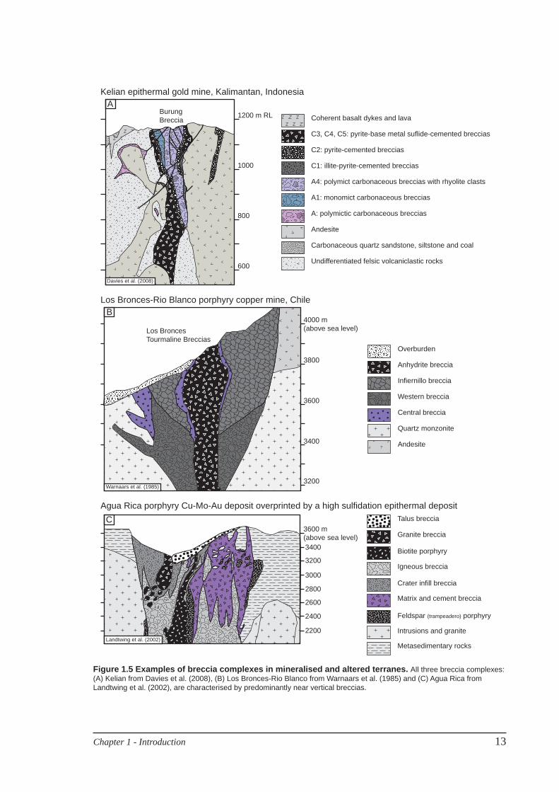
Breccia-dominated areas in altered and mineralised terranes are often termed ‘breccia
complexes’ (e.g. Kelian, Indonesia, Davies et al., 2008; Agua Rica Argentina, Landtwing
et al., 2002; Rio Blanco, Chile, Warnaars et al., 1985; Fig. 1.5). The breccia-dominated
host rocks of the Ladolam gold deposit have been termed a breccia complex by previous
workers (e.g. Davies and Ballantyne, 1987; Moyle et al., 1990; Carman, 1994). Single
breccia facies within a breccia complex may host or disrupt ore (e.g. the Braden breccia pipe
disrupts ore at El Teniente, Chile, Cannell et al., 2005; tourmaline breccias host ore at Rio
Blanco-Los Bronces, Chile, Warnaars et al., 1985; Vargas et al., 1999). It can be diffi cult to
identify new mineralised zones due to the complex interplay of facies relationships, grade
distributions and structural disruptions. Some breccia facies may behave as barriers to fl uid
fl ow (e.g., carbonaceous mud-matrix breccia at Kelian, Davies, 2002), whereas others may
focus mineralising hydrothermal fl uids (e.g. adularia-quartz-pyrite-cemented breccias at
Kelian, Davies, 2002). The breccia composition (clast, matrix and cement) and any syn- or
post-brecciation hydrothermal alteration may affect the physical properties of the breccia.
Routine logging of breccias in drill core can also prove challenging, particularly with regard
Chapter 1 - Introduction 13
Agua Rica porphyry Cu-Mo-Au deposit overprinted by a high sulfidation epithermal depositTalus breccia
Granite breccia
Biotite porphyry
Igneous breccia
Crater infill breccia
Matrix and cement breccia
Feldspar (trampeadero) porphyry
Intrusions and granite
Metasedimentary rocks
3600 m (above sea level)3400
3200
3000
2800
2600
2400
2200Landtwing et al. (2002)
C
Los Bronces-Rio Blanco porphyry copper mine, Chile
Overburden
Anhydrite breccia
Central breccia
Infiernillo breccia
Western breccia
Andesite
Quartz monzonite
4000 m (above sea level)
3800
3600
3400
3200
Los Bronces Tourmaline Breccias
Warnaars et al. (1985)
B
1200 m RL
1000
800
600
BurungBreccia
Davies et al. (2008)
ACoherent basalt dykes and lava
C3, C4, C5: pyrite-base metal suflide-cemented breccias
C2: pyrite-cemented breccias
C1: illite-pyrite-cemented breccias
A4: polymict carbonaceous breccias with rhyolite clasts
A1: monomict carbonaceous breccias
A: polymictic carbonaceous breccias
Carbonaceous quartz sandstone, siltstone and coal
Undifferentiated felsic volcaniclastic rocks
Andesite
Kelian epithermal gold mine, Kalimantan, Indonesia
Figure 1.5 Examples of breccia complexes in mineralised and altered terranes. All three breccia complexes: (A) Kelian from Davies et al. (2008), (B) Los Bronces-Rio Blanco from Warnaars et al. (1985) and (C) Agua Rica from Landtwing et al. (2002), are characterised by predominantly near vertical breccias.
14 Chapter 1 - Introduction
to recording suffi cient data to enable an understanding of their controls on the distribution of
mineralisation.
This study uses a descriptive logging scheme, adapted from McPhie et al., (1993),
which focuses on the compositional and textural variations at a variety of scales in order
to identify discrete breccia facies within a complex. Facies associations are then used to
unravel the relationships between the host lithofacies, grade distribution and hydrothermal
alteration.
1.6.2 Descriptive terminology
Breccia: A coarse-grained (>2 mm) clastic aggregate of angular rock fragments
(after Wentworth, 1935; Krynine, 1948). Conglomerate is the equivalent of breccia,
except that it is composed of round rock fragments. The components of breccia (and
conglomerate) may include clasts, matrix, cement and open space.
Clast: A single grain or particle in a clastic aggregate (Krynine, 1948). In this study,
clasts are defi ned as >2 mm diameter particles in a breccia or conglomerate.
Matrix: The grains or particles of a clastic aggregate that are smaller than, are in the
presence of, and fi ll the interstices between the clasts (Krynine, 1948). In this study,
matrix is defi ned as particles that are <2 mm diameter in a breccia or conglomerate.
Cement: Crystalline precipitate that infi ltrates around clasts and/or matrix (after Krynine,
1948). Cement may precipitate from an aqueous fl uid and may include ore and gangue
minerals (Davies et al., 2008a). Cement precipitated from aqueous fl uids is a diagnostic
component of most hydrothermal breccias (Davies et al., 2008a).
1.6.3 Volcanic, sedimentary and hydrothermal breccias: genetic terminology and distinguishing criteria
The literature on classifi cation of volcanic and sedimentary breccias is well established and
voluminous (e.g. Cas and Wright, 1987; McPhie et al., 1993). The literature on hydrothermal
breccias is not extensive or well established, in contrast to volcanic breccias. To simplify
Chapter 1 - Introduction 15
this review, only breccia facies that are relevant to the geological setting of Lihir Island are
considered. The approach of this study has been to attempt to identify end-member facies
whilst considering that overlaps in volcanic, sedimentary and hydrothermal processes may
occur.
Volcanic breccias: Volcanic breccias, distinguished primarily by their clast components,
internal organisation, and facies associations, are generated by both effusive and explosive
eruptions and are deposited at or near the Earth’s surface. Many pyroclastic facies are breccias
and most autoclastic facies (autobreccia and hyaloclastite) are breccias. Autoclastic deposits
are characteristically monomictic (McPhie et al., 1993). Monomictic clasts may be dense
or vesicular, porphyritic or aphanitic and have slabby, ragged or blocky shapes (McPhie et
al., 1993). Autoclastic breccias are often distinguished by their jigsaw-fi t or clast-rotated
internal organisation and association with coherent facies. Pyroclastic deposits are composed
of crystals, pumice or scoria, less vesicular juvenile clasts and lithic fragments (McPhie et
al., 1993). Pyroclasts are transported away from the vent or eruption column as a fl ow, fall
or surge (Cas and Wright, 1987). Flow deposits are massive, poorly sorted and have valley-
fi ll geometries (Branney and Kokelaar, 2002). Fall deposits are well sorted and bedded, and
mantle topography (Carey, 1991). Surge deposits are poorly sorted with lenticular thin beds
or laminations (Carey, 1991). Pyroclastic breccias are distinguished by not only components,
but by their conformable bed morphologies and chaotic internal organisation. In this thesis,
breccias that have volcanic components but whose facies association or geometries are
ambiguous, are modifi ed by the prefi x “volcanogenic”.
Sedimentary breccias: Sedimentary breccias form by processes such as weathering, erosion
and mass wasting and are composed of particles of pre-existing rocks, crystals, and/or
organics. Detrital sedimentary deposits are characterised by sedimentary structures that
refl ect the mechanisms that physically transport particles from the source area to the place
of deposition. In volcanic terranes, important transport processes include grain fl ow, slide
or slump, debris fl ows, debris avalanche, rock fall, and particulate traction, suspension and
fl otation transport in water or air (Cas and Wright, 1987; McPhie et al., 1993). Grain fl ow
16 Chapter 1 - Introduction
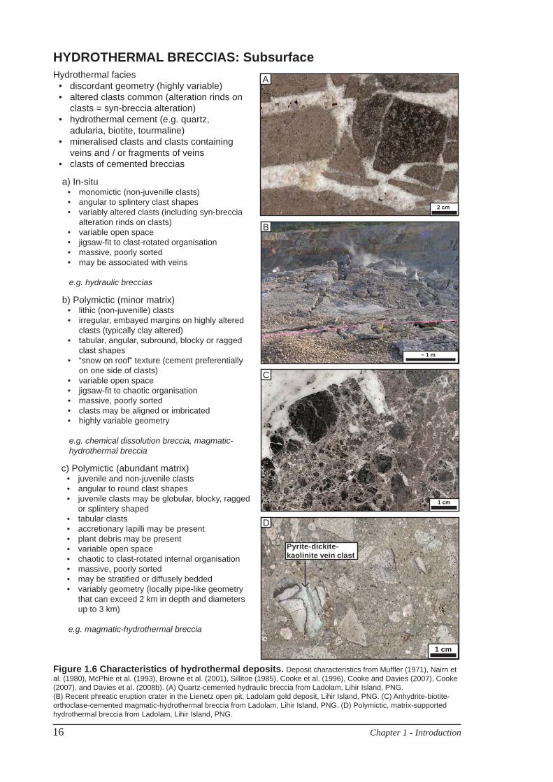
HYDROTHERMAL BRECCIAS: Subsurface
Figure 1.6 Characteristics of hydrothermal deposits. Deposit characteristics from Muffl er (1971), Nairn et al. (1980), McPhie et al. (1993), Browne et al. (2001), Sillitoe (1985), Cooke et al. (1996), Cooke and Davies (2007), Cooke (2007), and Davies et al. (2008b). (A) Quartz-cemented hydraulic breccia from Ladolam, Lihir Island, PNG. (B) Recent phreatic eruption crater in the Lienetz open pit, Ladolam gold deposit, Lihir Island, PNG. (C) Anhydrite-biotite-orthoclase-cemented magmatic-hydrothermal breccia from Ladolam, Lihir Island, PNG. (D) Polymictic, matrix-supported hydrothermal breccia from Ladolam, Lihir Island, PNG.
a) In-situmonomictic (non-juvenille clasts)• angular to splintery clast shapes• variably altered clasts (including syn-breccia • alteration rinds on clasts)variable open space• jigsaw-fi t to clast-rotated organisation• massive, poorly sorted• may be associated with veins•
e.g. hydraulic breccias
2 cm
A
c) Polymictic (abundant matrix)juvenile and non-juvenile clasts• angular to round clast shapes• juvenile clasts may be globular, blocky, ragged • or splintery shapedtabular clasts• accretionary lapilli may be present• plant debris may be present• variable open space• chaotic to clast-rotated internal organisation• massive, poorly sorted• may be stratifi ed or diffusely bedded• variably geometry (locally pipe-like geometry • that can exceed 2 km in depth and diameters up to 3 km)
e.g. magmatic-hydrothermal breccia
Hydrothermal faciesdiscordant geometry (highly variable)• altered clasts common (alteration rinds on • clasts = syn-breccia alteration)hydrothermal cement (e.g. quartz, • adularia, biotite, tourmaline)mineralised clasts and clasts containing • veins and / or fragments of veinsclasts of cemented breccias•
b) Polymictic (minor matrix)lithic (non-juvenille) clasts• irregular, embayed margins on highly altered • clasts (typically clay altered)tabular, angular, subround, blocky or ragged • clast shapes“snow on roof” texture (cement preferentially • on one side of clasts)variable open space• jigsaw-fi t to chaotic organisation• massive, poorly sorted• clasts may be aligned or imbricated• highly variable geometry•
e.g. chemical dissolution breccia, magmatic- hydrothermal breccia
B
C
D
1 cm
Pyrite-dickite-kaolinite vein clast
1 cm
~ 1 m
Chapter 1 - Introduction 17
deposits are distinguished by reversely graded beds with steep primary dips. Slide or slump
and debris avalanche deposits are characterised by a large blocks of intact stratigraphy
within a massive, very poorly sorted breccia (Glicken, 1991). The presence of large blocks
produces distinctive hummocky topography. Debris fl ow deposits are very poorly sorted
and though typically non-graded, reverse graded beds do occur (Lowe, 1982). Turbidites
are characterised by normally graded beds and commonly occur as thick sequences where
normally graded beds are of uniform thickness (Lowe, 1982). Turbidity currents suspend
sediment in water and thus deposits are indicative of a subaqueous environment, below wave
base.
Hydrothermal breccias: Hydrothermal breccias are generated by the interaction of
hydrothermal fl uid with wall rock and/or magma, irrespective of the source of the hydrothermal
fl uid or nature of the wall rock (Burnham and Ohmoto, 1980). Diagnostic properties of
hydrothermal deposits (although not always present) are discordant geometries, hydrothermal
cement (e.g. quartz, adularia, and tourmaline) and wall rock clasts that have evidence of pre-
existing hydrothermal conditions (altered or mineralised clast or clasts containing veins and
fragments of veins; Sillitoe, 1985). The components and characteristics of in-situ jigsaw fi t
and polymictic hydrothermal deposits are summarised in Figure 1.6.
Hydrothermal processes that can fragment rock include hydraulic or fl uid over-
pressurisation (e.g. Jebrak, 1997), chemical dissolution (e.g. Wenrich, 1985), magmatic
volatile exsolution during second boiling in the magmatic-hydrothermal environment
(Burnham and Ohmoto, 1980; Burnham, 1985), steam expansion (e.g. Muffl er et al., 1971;
Nelson and Giles, 1985) and quench fragmentation resulting from the interaction of external
hydrothermal fl uid with magma (e.g. Lorenz and Kurszlaukis, 2007). Transportation
processes include gravitational collapse and fl uidisation or fl ow (McCallum, 1985; Sillitoe,
1985). Often, the main difference between in-situ and polymictic hydrothermal deposits is
whether or not processes are repeated; i.e. multiple fragmentation and transportation events;
a hydraulic breccia may end up polymictic and bedded and matrix-rich if the processes go
on long enough.
Although surfi cial deposits do occur (e.g. phreatic eruption deposits), hydrothermal
18 Chapter 1 - Introduction
facies are best preserved in the subsurface where they have discordant pipe, dyke or vein
geometries and cut basement rock lithologies. Distinctions between deeper and shallower
subsurface depositional environments may be determined by the associated cement mineral
assemblage (e.g. biotite versus halloysite) or from temperature and pressure conditions
determined by fl uid inclusion studies.
Complications that can arise in an active hydrothermal system in a geologically young
volcanic centre include the overlap of volcanic and hydrothermal fragmentation processes
and products. Careful documentation of breccia geometries and contact relationships are
therefore critical for correct genetic interpretations (e.g. Sillitoe et al., 1984; Landtwing et
al., 2002; Cannell et al., 2005). In the case of the Ladolam deposit, the shallow-level breccia-
rich volcanic environment has complicated the recognition of hydrothermal facies that lack
obvious cement and / or diagnostic clast components. The geometry of breccia facies is
resolved in the following chapters by careful description of the components and textures.