chapter 1 introduction - courses
TRANSCRIPT

Chapter 1Introduction
A note on the use of these PowerPoint slides:We’re making these slides freely available to all (faculty, students, readers). They’re in PowerPoint form so you see the animations; and can add, modify, and delete slides (including this one) and slide content to suit your needs. They obviously represent a lot of work on our part. In return for use, we only ask the following:
▪ If you use these slides (e.g., in a class) that you mention their source (after all, we’d like people to use our book!)
▪ If you post any slides on a www site, that you note that they are adapted from (or perhaps identical to) our slides, and note our copyright of this material.
For a revision history, see the slide note for this page.
Thanks and enjoy! JFK/KWR
All material copyright 1996-2020J.F Kurose and K.W. Ross, All Rights Reserved
Computer Networking: A Top-Down Approach 8th edition Jim Kurose, Keith RossPearson, 2020

Part I: The Internet(with a capital I)

Internet
The Internet: a “nuts and bolts” view
mobile network
home network
enterprisenetwork
national or global ISP
local or regional ISP
datacenter network
content provider network
Packet switches: forward packets (chunks of data)▪ routers, switches
Communication links▪ fiber, copper, radio, satellite
▪ transmission rate: bandwidth
Billions of connected computing devices: ▪ hosts = end systems
▪ running network apps at Internet’s “edge”
Networks▪ collection of devices, routers,
links: managed by an organization

“Fun” Internet-connected devices
IP picture frame Web-enabled toaster +
weather forecaster
Internet phones
Internet
refrigerator
Slingbox: remote
control cable TV
Tweet-a-watt:
monitor energy use
sensorized,
bed
mattress
Security Camera
Amazon Echo
Pacemaker & Monitor
Others?Fitbit
AR devices

▪ Internet: “network of networks”• Interconnected ISPs
The Internet: a “nuts and bolts” viewmobile network
home network
enterprisenetwork
national or global ISP
local or regional ISP
datacenter network
content provider network
▪ protocols are everywhere• control sending, receiving of
messages• e.g., HTTP (Web), streaming video,
Skype, TCP, IP, WiFi, 4G, Ethernet
▪ Internet standards• RFC: Request for Comments
• IETF: Internet Engineering Task Force
Ethernet
HTTP
SkypeIP
WiFi
4G
TCP
Streamingvideo

▪ Infrastructure that provides services to applications:• Web, streaming video, multimedia
teleconferencing, email, games, e-commerce, social media, inter-connected appliances, …
The Internet: a “service” viewmobile network
home network
enterprisenetwork
national or global ISP
local or regional ISP
datacenter network
content provider networkHTTP
Skype
Streamingvideo
▪ provides programming interface to distributed applications:• “hooks” allowing sending/receiving
apps to “connect” to, use Internet transport service
• provides service options, analogous to postal service

What’s a protocol?
Human protocols:▪ “what’s the time?”
▪ “I have a question”
▪ introductions
… specific messages sent
… specific actions taken when message received, or other events
Network protocols:▪ computers (devices) rather than humans
▪ all communication activity in Internet governed by protocols
Protocols define the format, order of messages sent and received among network entities, and actions taken
on msg transmission, receipt

What’s a protocol?A human protocol and a computer network protocol:
Hi
Hi
Got thetime?
2:00
time
TCP connectionresponse
<file>
TCP connectionrequest
GET http://gaia.cs.umass.edu/kurose_ross

A closer look at Internet structuremobile network
home network
enterprisenetwork
national or global ISP
local or regional ISP
datacenter network
content provider network
Network edge:
▪ hosts: clients and servers
▪ servers often in data centers

Client vs Server
▪When used in connection-oriented protocols:• Client: party that creates
connection• Server: party that awaits
connections
▪When used in application-level protocols:• Client: party that requests
something• Server: party that provides
something
▪When used to categorize end hosts:• Client: computer that mostly runs
programs that act as application-level clients
• Server: computer that mostly runs programs that act as application-level servers

A closer look at Internet structuremobile network
home network
enterprisenetwork
national or global ISP
local or regional ISP
datacenter network
content provider network
Network edge:
▪ hosts: clients and servers
▪ servers often in data centers
Access networks, physical media:
▪wired, wireless communication links

A closer look at Internet structure
Network edge:
▪ hosts: clients and servers
▪ servers often in data centers
Access networks, physical media:
▪wired, wireless communication links
Network core: ▪ interconnected routers▪network of networks
mobile network
home network
enterprisenetwork
national or global ISP
local or regional ISP
datacenter network
content provider network
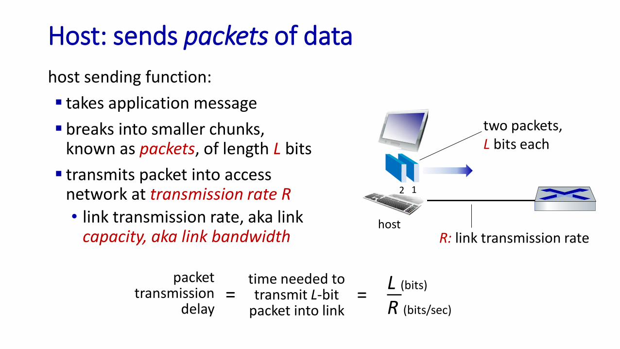
Host: sends packets of data
host sending function:
▪ takes application message
▪ breaks into smaller chunks, known as packets, of length L bits
▪ transmits packet into access network at transmission rate R
• link transmission rate, aka link capacity, aka link bandwidth R: link transmission rate
host
12
two packets, L bits each
packettransmission
delay
time needed totransmit L-bit
packet into link
L (bits)
R (bits/sec)= =

Links: physical media
▪ bit: propagates betweentransmitter/receiver pairs
▪ physical link: what lies between transmitter & receiver
▪ guided media: • signals propagate in solid
media: copper, fiber, coax
▪ unguided media:• signals propagate freely,
e.g., radio
Twisted pair (TP)▪ two insulated copper wires
• Category 5: 100 Mbps, 1 Gbps Ethernet
• Category 6: 10Gbps Ethernet
▪ Other examples:Coax, FiberWireless links; Satellite;

Access networks and physical media
mobile network
home network
enterprisenetwork
national or global ISP
local or regional ISP
datacenter network
content provider network
Q: How to connect end systems to edge router?
▪ residential access nets
▪ institutional access networks (school, company)
▪ mobile access networks (WiFi, 4G/5G)
What to look for: ▪ transmission rate (bits per second) of access
network?
▪ shared or dedicated access among users?

Access networks: cable-based access
cablemodem
splitter
…
cable headend
Channels
V
I
D
E
O
V
I
D
E
O
V
I
D
E
O
V
I
D
E
O
V
I
D
E
O
V
I
D
E
O
D
A
T
A
D
A
T
A
C
O
N
T
R
O
L
1 2 3 4 5 6 7 8 9
frequency division multiplexing (FDM): different channels transmitted in different frequency bands

Access networks: cable-based access
cablemodem
splitter
…
cable headend
data, TV transmitted at different frequencies over shared cable
distribution network
▪ HFC: hybrid fiber coax• asymmetric: up to 40 Mbps – 1.2 Gbs downstream transmission rate, 30-100 Mbps
upstream transmission rate
▪ network of cable, fiber attaches homes to ISP router• homes share access network to cable headend
cable modemtermination systemCMTS
ISP

Example:Dr. Back’s Cable ModemSignal Status page.4 downstream channels (bonded) 34-37 and4 upstream channels (25-28)
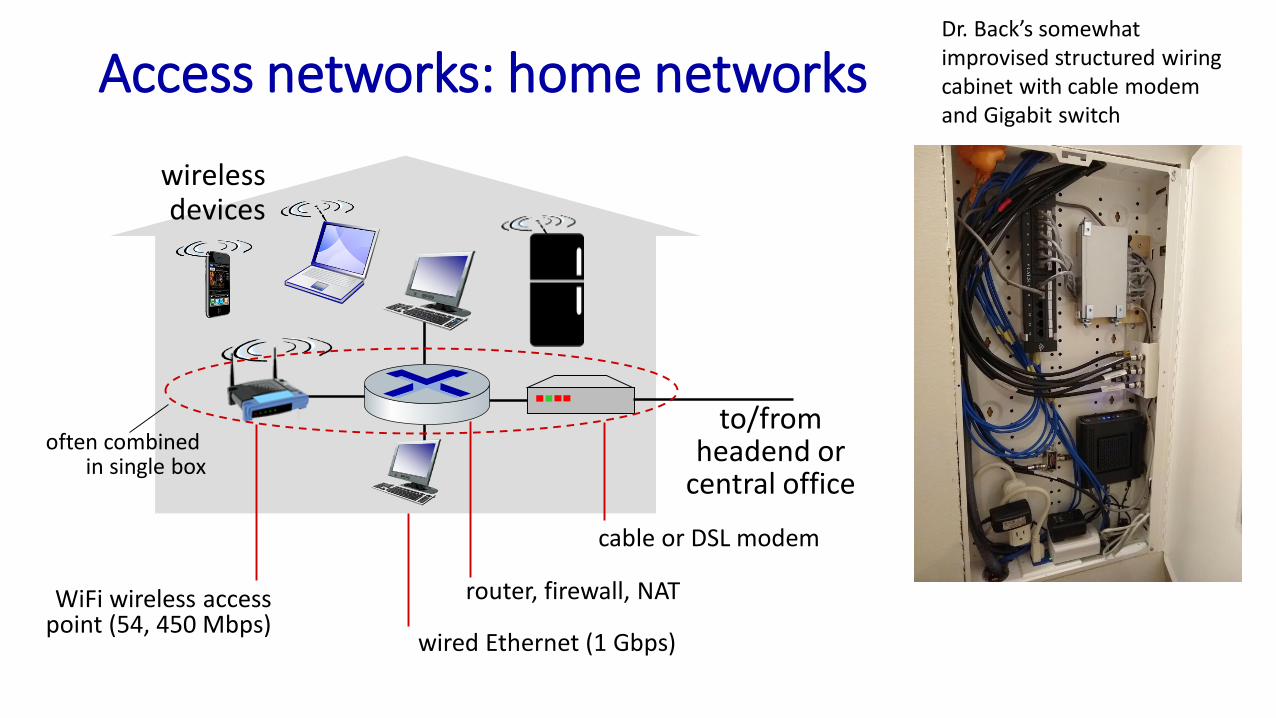
Access networks: home networks
to/from headend or
central office
cable or DSL modem
router, firewall, NAT
wired Ethernet (1 Gbps)
WiFi wireless access point (54, 450 Mbps)
wirelessdevices
often combined in single box
Dr. Back’s somewhatimprovised structured wiringcabinet with cable modemand Gigabit switch

Wireless access networksShared wireless access network connects end system to router
▪ via base station aka “access point”
Wireless local area networks (WLANs)
▪ typically within or around building (~100 ft)
▪ 802.11b/g/n (WiFi): 11, 54, 450 Mbps transmission rate
to Internetto Internet
Wide-area cellular access networks▪ provided by mobile, cellular network
operator (10’s km)
▪ 10’s Mbps
▪ 4G cellular networks (5G coming)

Access networks: enterprise networks
▪ companies, universities, etc.
▪ mix of wired, wireless link technologies, connecting a mix of switches and routers (we’ll cover differences shortly)
▪ Ethernet: wired access at 100Mbps, 1Gbps, 10Gbps
▪ WiFi: wireless access points at 11, 54, 450 Mbps
Ethernet switch
institutional mail,web servers
institutional router
Enterprise link to ISP (Internet)

The network core
▪mesh of interconnected routers
▪packet-switching: hosts break application-layer messages into packets• forward packets from one router
to the next, across links on path from source to destination
• each packet transmitted at full link capacity
mobile network
home network
enterprisenetwork
national or global ISP
local or regional ISP
datacenter network
content provider network

Two key network-core functions
Forwarding:
▪ local action: move arriving packets from router’s input link to appropriate router output link
1
23
destination address in arrivingpacket’s header
routing algorithm
header value output link
0100
0101
0111
1001
3
2
2
1
Routing:
▪ global action: determine source-destination paths taken by packets
▪ routing algorithms
local forwarding tablelocal forwarding table
routing algorithm

Internet structure: a “network of networks”
▪ Hosts connect to Internet via access Internet Service Providers (ISPs)• residential, enterprise (company, university, commercial) ISPs
▪ Access ISPs in turn must be interconnected• so that any two hosts can send packets to each other
▪ Resulting network of networks is very complex• evolution was driven by economics and national policies
▪ Let’s take a stepwise approach to describe current Internet structure
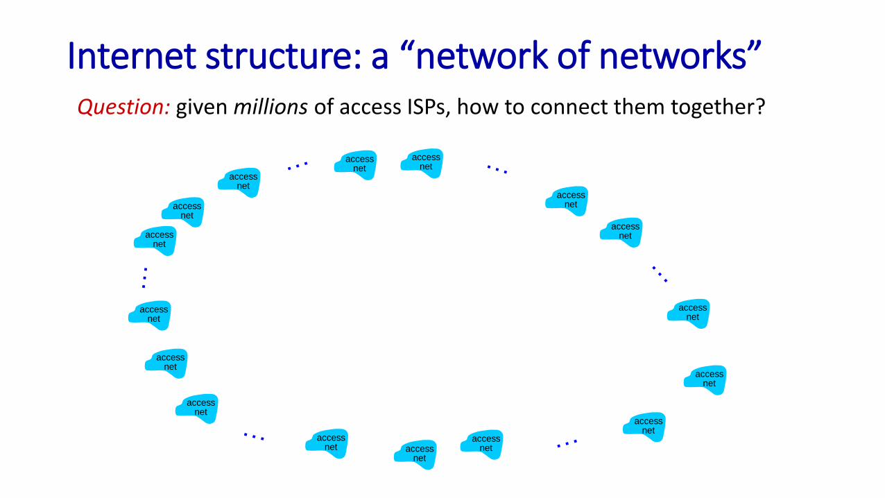
Internet structure: a “network of networks”Question: given millions of access ISPs, how to connect them together?
accessnet
accessnet
accessnet
accessnet
accessnet
accessnet
accessnet
accessnet
accessnet
accessnet
accessnet
accessnet
accessnet
accessnetaccess
net
accessnet

Internet structure: a “network of networks”Question: given millions of access ISPs, how to connect them together?
accessnet
accessnet
accessnet
accessnet
accessnet
accessnet
accessnet
accessnet
accessnet
accessnet
accessnet
accessnet
accessnet
accessnetaccess
net
accessnet
connecting each access ISP to each other directly doesn’t scale:
O(N2) connections.

Internet structure: a “network of networks”Option: connect each access ISP to one global transit ISP?
Customer and provider ISPs have economic agreement.
globalISP
accessnet
accessnet
accessnet
accessnet
accessnet
accessnet
accessnet
accessnet
accessnet
accessnet
accessnet
accessnet
accessnet
accessnetaccess
net
accessnet

ISP A
ISP C
ISP B
Internet structure: a “network of networks”
accessnet
accessnet
accessnet
accessnet
accessnet
accessnet
accessnet
accessnet
accessnet
accessnet
accessnet
accessnet
accessnet
accessnetaccess
net
accessnet
But if one global ISP is viable business, there will be competitors ….

ISP A
ISP C
ISP B
Internet structure: a “network of networks”
accessnet
accessnet
accessnet
accessnet
accessnet
accessnet
accessnet
accessnet
accessnet
accessnet
accessnet
accessnet
accessnet
accessnetaccess
net
accessnet
But if one global ISP is viable business, there will be competitors …. who will want to be connected
IXP
peering link
Internet exchange point
IXP

ISP A
ISP C
ISP B
Internet structure: a “network of networks”
accessnet
accessnet
accessnet
accessnet
accessnet
accessnet
accessnet
accessnet
accessnet
accessnet
accessnet
… and regional networks may arise to connect access nets to ISPs
IXP
IXP
accessnet
accessnet
regional ISPaccess
net accessnet
accessnet

ISP A
ISP C
ISP B
Internet structure: a “network of networks”
accessnet
accessnet
accessnet
accessnet
accessnet
accessnet
accessnet
accessnet
accessnet
accessnet
accessnet
… and content provider networks (e.g., Google, Microsoft, Akamai) may run their own network, to bring services, content close to end users
IXP
IXP
accessnet
accessnet
accessnet access
net
accessnet
Content provider network
regional ISP

Internet structure: a “network of networks”
Tier 1 ISP Tier 1 ISP
Regional ISP Regional ISP
accessISP
accessISP
accessISP
accessISP
accessISP
accessISP
accessISP
accessISP
IXP IXP IXP
At “center”: small # of well-connected large networks
▪ “tier-1” commercial ISPs (e.g., Level 3, Sprint, AT&T, NTT), national & international coverage
▪ content provider networks (e.g., Google, Facebook): private network that connects its data centers to Internet, often bypassing tier-1, regional ISPs

Tier-1 ISP Network map: Sprint (2019)
links to/from Sprint customer networks
links to peering networks
to/from other Sprint PoPS
…
… … …
…
POP: point-of-presence

https://www.internet2.edu/media/medialibrary/2020/02/19/ConnectorsMap_202002_XaFyViw.pdf

Part II: On Delay & Throughput
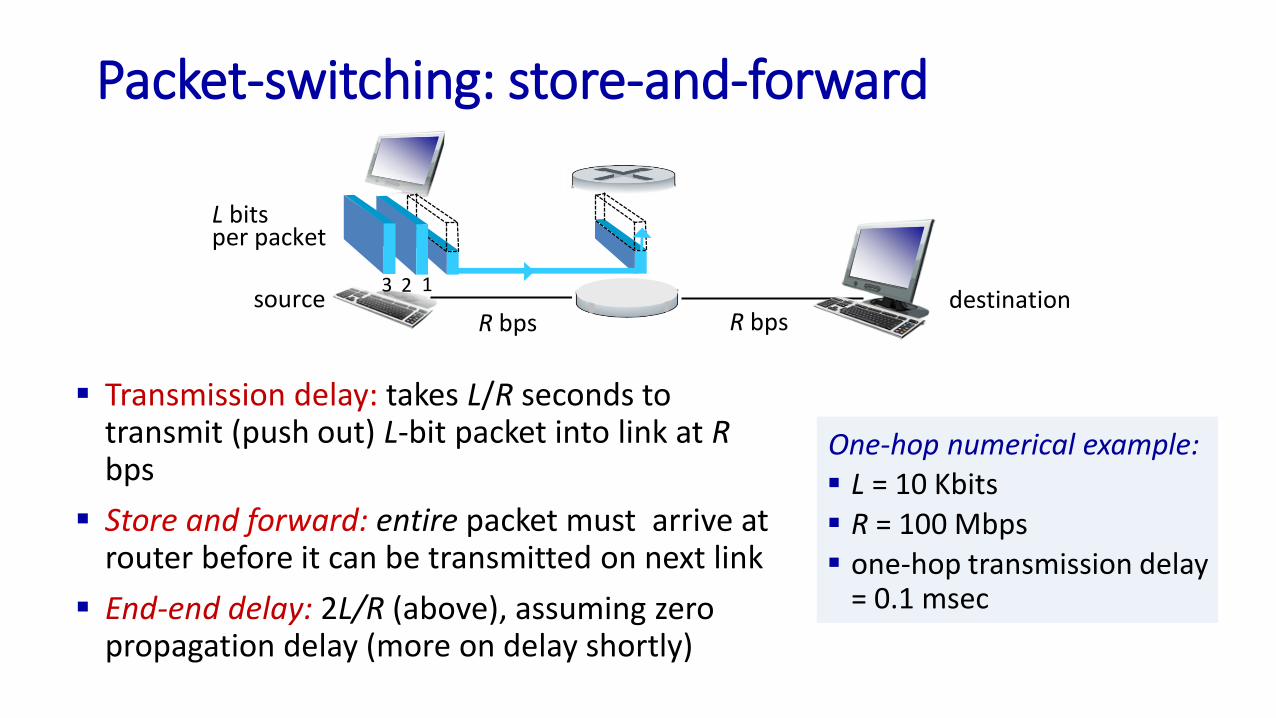
Packet-switching: store-and-forward
▪ Transmission delay: takes L/R seconds to transmit (push out) L-bit packet into link at Rbps
▪ Store and forward: entire packet must arrive at router before it can be transmitted on next link
▪ End-end delay: 2L/R (above), assuming zero propagation delay (more on delay shortly)
sourceR bps
destination123
L bitsper packet
R bps
One-hop numerical example:▪ L = 10 Kbits
▪ R = 100 Mbps▪ one-hop transmission delay
= 0.1 msec

Packet-switching: queueing delay, loss
Packet queuing and loss: if arrival rate (in bps) to link exceeds transmission rate (bps) of link for a period of time:
▪ packets will queue, waiting to be transmitted on output link
▪ packets can be dropped (lost) if memory (buffer) in router fills up
A
B
CR = 100 Mb/s
R = 1.5 Mb/sD
Equeue of packets
waiting for output link
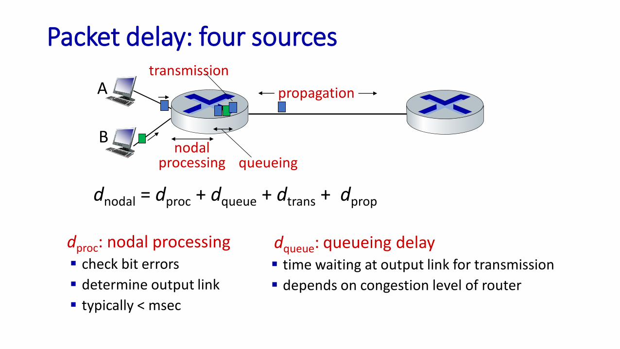
Packet delay: four sources
dproc: nodal processing▪ check bit errors
▪ determine output link
▪ typically < msec
dqueue: queueing delay▪ time waiting at output link for transmission
▪ depends on congestion level of router
propagation
nodalprocessing queueing
dnodal = dproc + dqueue + dtrans + dprop
A
B
transmission

Packet delay: four sources
propagation
nodalprocessing queueing
dnodal = dproc + dqueue + dtrans + dprop
A
B
transmission
dtrans: transmission delay:▪ L: packet length (bits)
▪ R: link transmission rate (bps)
▪ dtrans = L/R
dprop: propagation delay:▪ d: length of physical link
▪ s: propagation speed (~2x10⁸ m/sec)
▪ dprop = d/sdtrans and dprop
very different* Check out the online interactive exercises: http://gaia.cs.umass.edu/kurose_ross
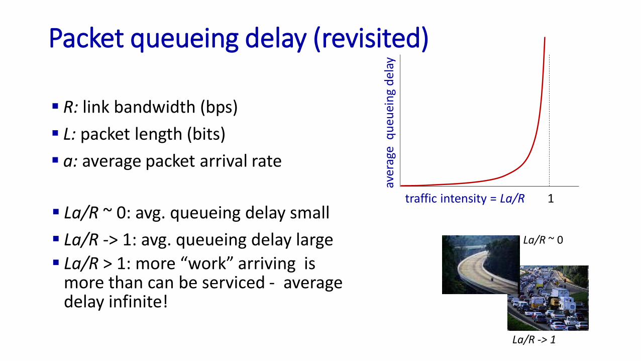
Packet queueing delay (revisited)
▪ R: link bandwidth (bps)
▪ L: packet length (bits)
▪ a: average packet arrival rate
▪ La/R ~ 0: avg. queueing delay small
▪ La/R -> 1: avg. queueing delay large
▪ La/R > 1: more “work” arriving is more than can be serviced - average delay infinite!
La/R ~ 0
La/R -> 1
traffic intensity = La/R
aver
age
qu
euei
ng
del
ay
1

Throughput
▪ throughput: rate (bits/time unit) at which bits are being sent from sender to receiver
• instantaneous: rate at given point in time
• average: rate over longer period of time
server, withfile of F bits
to send to client
link capacityRs bits/sec
link capacityRc bits/sec
server sends bits (fluid) into pipe
pipe that can carryfluid at rate(Rs bits/sec)
pipe that can carryfluid at rate(Rc bits/sec)

Throughput
Rs < Rc What is average end-end throughput?
Rs bits/sec Rc bits/sec
Rs > Rc What is average end-end throughput?
link on end-end path that constrains end-end throughput
bottleneck link
Rs bits/sec Rc bits/sec

Throughput: network scenario
10 connections (fairly) share backbone bottleneck link R bits/sec
Rs
Rs
Rs
Rc
Rc
Rc
R
▪ per-connection end-end throughput: min(Rc,Rs,R/10)
▪ in practice: Rc or Rs is often bottleneck
* Check out the online interactive exercises for more
examples: http://gaia.cs.umass.edu/kurose_ross/

Part III: On Layering

Protocol “layers” and reference models
Networks are complex,with many “pieces”:▪ hosts
▪ routers▪ links of various media
▪ applications
▪ protocols
▪ hardware, software
Question:
is there any hope of organizing structure of
network?
…. or at least our discussion of networks?

Why layering?
dealing with complex systems:
▪ explicit structure allows identification, relationship of complex system’s pieces• layered reference model for discussion
▪ modularization eases maintenance, updating of system• change in layer's service implementation: transparent to rest of
system
▪ layering considered harmful?
▪ layering in other complex systems?

Internet protocol stack
▪ application: supporting network applications• IMAP, SMTP, HTTP
▪ transport: process-process data transfer• TCP, UDP
▪ network: routing of datagrams from source to destination• IP, routing protocols
▪ link: data transfer between neighboring network elements• Ethernet, 802.11 (WiFi), PPP
▪ physical: bits “on the wire”
application
transport
network
link
physical
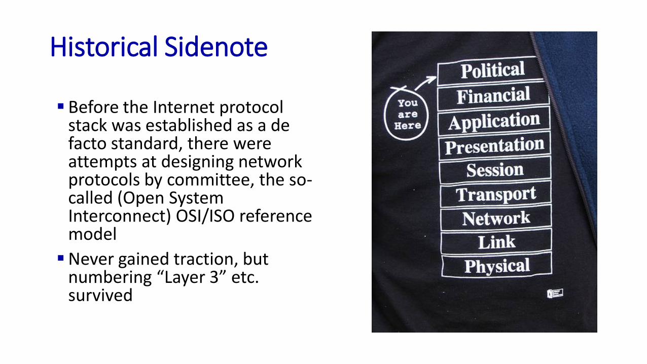
Historical Sidenote
▪ Before the Internet protocol stack was established as a de facto standard, there were attempts at designing network protocols by committee, the so-called (Open System Interconnect) OSI/ISO reference model
▪Never gained traction, but numbering “Layer 3” etc. survived

Services vs Protocols
(horizontal component)
▪ Layer k may interact with peer layer k only via protocolsSource: Tanenbaum
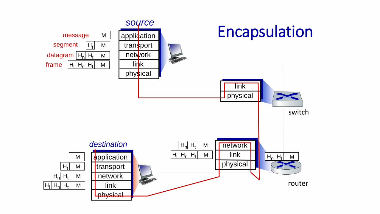
Encapsulationsource
application
transport
network
link
physical
HtHn M
segment Ht
datagram
destination
application
transport
network
link
physical
HtHnHl M
HtHn M
Ht M
M
network
link
physical
link
physical
HtHnHl M
HtHn M
HtHn M
HtHnHl M
router
switch
message M
Ht M
Hn
frame

TCP/IP Hourglass View
UDP
Ethernet
IP
WirelessATM
TCP
NFSDNS FTPHTTP
Host-To-Network
Internet
Application
Transport

Typical Implementation
may cross
multiple
boundaries!
User App
Socket
Network Device
IP Layer
TCP Layer
user
Kernel:“top-half”
Kernel:“sw interrupt”
Kernel:“hw interrupt”