chapter 03 - superstructure section 01 bridge deck (sup …sup-bd(sg)-103 2.0 07/03/2017. approval...
TRANSCRIPT

OFFICE OF STRUCTURES STRUCTURAL DETAIL MANUAL
Chapter 03 - Superstructure
SECTION 01
BRIDGE DECK (SUP-BD)

OFFICE OF STRUCTURES STRUCTURAL DETAIL MANUAL
Chapter 03 - Superstructure
Section 01 – Bridge Deck
SUB-SECTION 01
BRIDGE DECK DETAILS
(SUP-BD(DT))

1
Scale: None
1
Note:
For detail of construction joint see
LAYOUT OF TRANSVERSEJOINT FOR SKEWED BRIDGE DECK
PLAN
c
c
c
c
of Exterior Stringer
of Exterior Stringer
of Stringer
of Stringer
Placement Placement
Transverse Construction Joint *
*
DATE:
STATE HIGHWAY ADMINISTRATION
DEPARTMENT OF TRANSPORTATION
STATE OF MARYLAND
SHEET OF
APPROVAL
OFFICE OF STRUCTURES
DIRECTOR
OFFICE OF STRUCTURES
SUP-BD(DT)-101
SU
PE
R-B
RID
GE
DE
CK
Outside face
of superstructure.
Outside face
of superstructure.
Transverse construction joints to be
placed parallel to center line bearing
for piers and abutments. If substructure
units are not parallel then transverse
construction joints shall be parallel to
the closest substructure unit center line
of bearing.
Transverse construction joints to be
perpendicular to the outside face of
superstructure for the portion of the
deck outside of the exterior stringer.
09/13/1994
VERSION
DETAIL NO.
1.0
Detail No. SUP-BD(DT)-102.

Deck S
lab
Stage of construction
poured first.
Top of slab
1.
2.
1 1
Notes:
Reinforcing steel to be continuous
DATE:
STATE HIGHWAY ADMINISTRATION
DEPARTMENT OF TRANSPORTATION
STATE OF MARYLAND
SHEET OF
APPROVAL
Main slab
steel
1 1/2 ’’
3 3/
4 ’’
2’’
1 3/4
’’
Scale: 1 1/2 ’’ = 1’-0’’
thru joint.
SECTION
BRIDGE DECK SLAB DETAIL ATTRANSVERSE CONSTRUCTION JOINT
OFFICE OF STRUCTURES
DIRECTOR
OFFICE OF STRUCTURES
SUP-BD(DT)-102
SU
PE
R - B
RID
GE
DE
CK
VERSION
DETAIL NO.
2.0
Bottom longitudinal steel lap = 3’-6’’
Top longitudinal steel lap = 2’-5’’ (#5 bars)
3’-7’’ (#6 bars)
Entire face of construction joint
shall be coated with an approved
epoxy bonding compound.
See note 2
3. See Detail No. SUP-BD(DT)-201 for bridge
deck slab reinforcing splices.
04/30/2018

1 2
DATE:
STATE HIGHWAY ADMINISTRATION
DEPARTMENT OF TRANSPORTATION
STATE OF MARYLAND
SHEET OF
APPROVAL
SECTION
**
OPTIONAL TRANSVERSE TRUSS BAR SPLICE
Scale: None
SECTION
Scale: None
OPTIONAL TRANSVERSE STRAIGHT BAR SPLICE
OFFICE OF STRUCTURES
DIRECTOR
OFFICE OF STRUCTURES
SUP-BD(DT)-201
SU
PE
R - B
RID
GE
DE
CK
Optional splices shown may not be used for decks
45’-0’’ or less in width.
Bay (typ.)
Stringer (typ.)
Stringer (typ.)
Bay (typ.)
DETAIL NO.
VERSION
2.0
Note:
See sheet 2 of 2 for longitudinal
steel splice details.
Bottom splice
2’-8’’
Top splice
1’-10’’
**
BRIDGE DECK SLAB REINFORCINGSPLICE LOCATIONS
This splice location can only be used if truss bottom
leg dimension is greater than or equal to lap length.
No more than one splice may occur over every 3rd
stringer (top splice) or within 3rd bay (bottom splice).
All bars must splice in the same plane (all in top of slab
or all in bottom of slab).
Top splice 1’-10’’
centered over stringer
Bottom
splice
2’-8’’
centered in bay
04/30/2018

2 2
DATE:
STATE HIGHWAY ADMINISTRATION
DEPARTMENT OF TRANSPORTATION
STATE OF MARYLAND
SHEET OF
APPROVAL
Scale: None
bars (typ.)
splice
splice splice splice
L Bearingc
Scale: None
PLAN
OFFICE OF STRUCTURES
DIRECTOR
OFFICE OF STRUCTURES
SUP-BD(DT)-201
SU
PE
R - B
RID
GE
DE
CKDETAIL NO.
VERSION
2.0
Bottom longitudinal
Additional
longitudinal bars
over pier (typ.)
Normal top
longitudinal
bars (typ.)
LONGITUDINAL SPLICES
splice splice splice
Additional longitudinal
#6 bars (3’-7’’ splice)
Top normal longitudinal
bars (2’-5’’ splice)
Bottom longitudinal
bars (3’-6’’ splice)
BRIDGE DECK SLAB REINFORCINGSPLICE LOCATIONS
BRIDGE DECK SECTION
Note:
This section shows the
typical location of the
longitudinal reinforcing
bars for reference.
04/30/2018
OFFICE OF STRUCTURES STRUCTURAL DETAIL MANUAL
Chapter 03 - Superstructure
Section 01 – Bridge Deck
SUB-SECTION 02
BRIDGE DECK STEEL GIRDERS
(SUP-BD(SG))
APPROVAL
DIRECTOR
OFFICE OF STRUCTURES
DATE:
VERSION
STATE HIGHWAY ADMINISTRATION
DEPARTMENT OF TRANSPORTATION
STATE OF MARYLAND
OFFICE OF STRUCTURES
DETAIL NO. SHEET OF1 2
GENERAL NOTES AND BAR SPACINGBRIDGE DECK SLAB FOR STEEL GIRDERS
SUP-BD(SG)-101
SUP
ER - B
RID
GE
DE
CK
1.0
Design: 1.
2. c
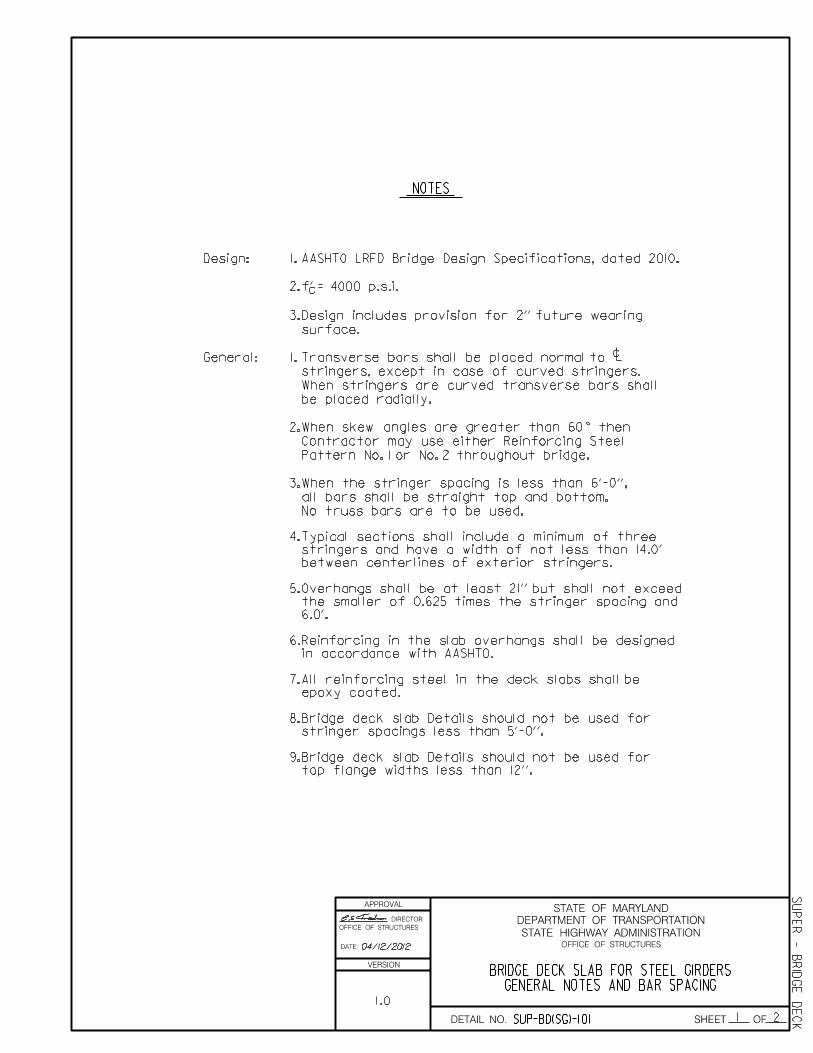
3.Design includes provision for 2'' future wearing
surface.
General: 1.Transverse bars shall be placed normal to
stringers, except in case of curved stringers.
When stringers are curved transverse bars shall
be placed radially.
2.When skew angles are greater than 60 then
Contractor may use either Reinforcing Steel
Pattern No. 1 or No. 2 throughout bridge.
c
3.
NOTES
No truss bars are to be used.
Typical sections shall include a minimum of three
stringers and have a width of not less than 14.0'
between centerlines of exterior stringers.
Overhangs shall be at least 21'' but shall not exceed
the smaller of 0.625 times the stringer spacing and
4.
5.
f' = 4000 p.s.i.
When the stringer spacing is less than 6'-0'',
AASHTO LRFD Bridge Design Specifications, dated 2010.
all bars shall be straight top and bottom.
9.
8.
7.
6.
04/12/2012
top flange widths less than 12''.
Bridge deck slab Details should not be used for
stringer spacings less than 5'-0''.
Bridge deck slab Details should not be used for
epoxy coated.
All reinforcing steel in the deck slabs shall be
in accordance with AASHTO.
Reinforcing in the slab overhangs shall be designed
6.0'.
APPROVAL
DIRECTOR
OFFICE OF STRUCTURES
DATE:
VERSION
STATE HIGHWAY ADMINISTRATION
DEPARTMENT OF TRANSPORTATION
STATE OF MARYLAND
OFFICE OF STRUCTURES
DETAIL NO. SHEET OF2 2
GENERAL NOTES AND BAR SPACINGBRIDGE DECK SLAB FOR STEEL GIRDERS
SUP
ER - B
RID
GE
DE
CKSUP-BD(SG)-101
1.0
c c c c
c
*
**
c
Spacing of steel
- -
Straight Bars
Spacing of steel
- -
Straight Bars
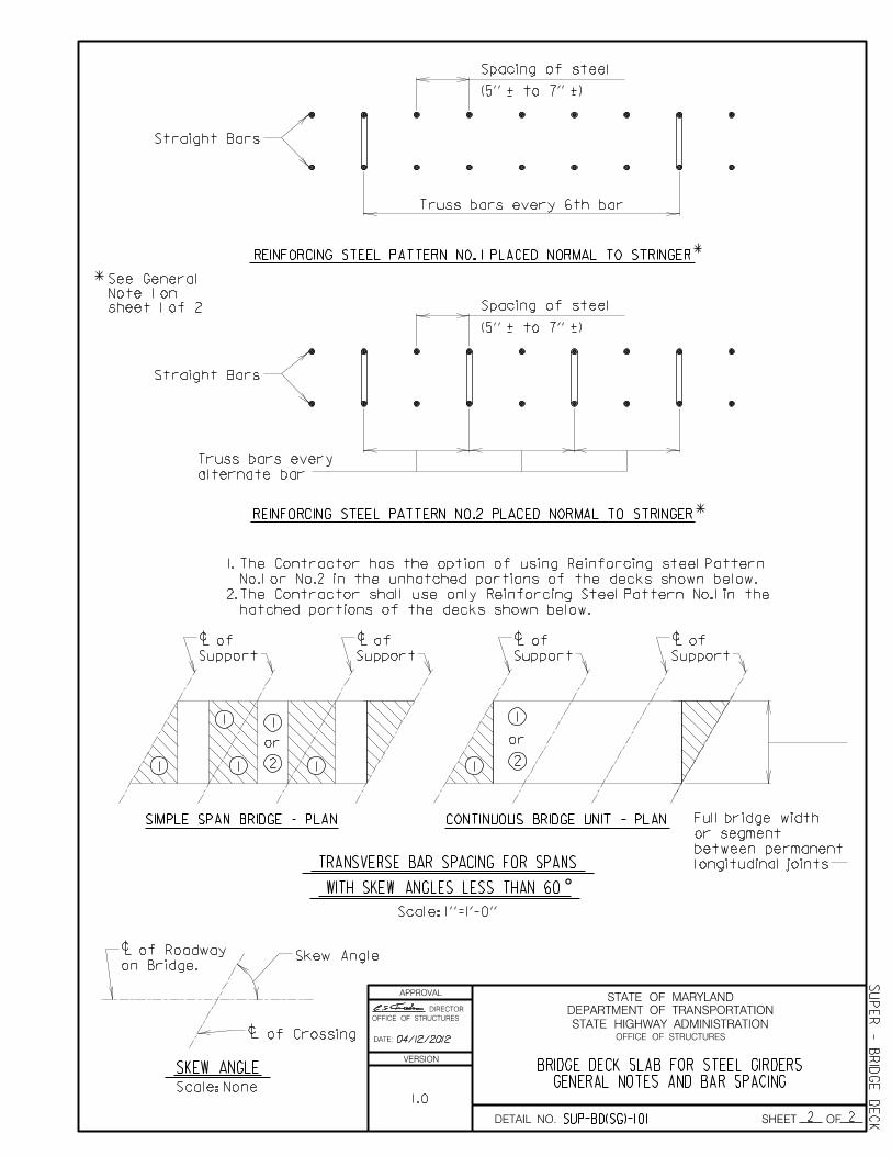
The Contractor has the option of using Reinforcing steel Pattern
No.1 or No.2 in the unhatched portions of the decks shown below.
1.
2.The Contractor shall use only Reinforcing Steel Pattern No.1 in the
hatched portions of the decks shown below.
1
1 11
22
or or
1 1 1
TRANSVERSE BAR SPACING FOR SPANS
WITH SKEW ANGLES LESS THAN 60
or segment
between permanent
of
Support
of
Support
of
Support
of
Support
Skew Angle
Scale: 1''=1'-0''
SIMPLE SPAN BRIDGE - PLAN CONTINUOUS BRIDGE UNIT - PLAN Full bridge width
longitudinal joints
REINFORCING STEEL PATTERN NO.2 PLACED NORMAL TO STRINGER
REINFORCING STEEL PATTERN NO. 1 PLACED NORMAL TO STRINGER
(5'' + to 7'' +)
Truss bars every 6th bar
(5'' + to 7'' +)
of Roadway
on Bridge.
sheet 1 of 2
Note 1 on
See General
alternate bar
Truss bars every
SKEW ANGLE
Scale: None
of Crossing04/12/2012
APPROVAL
DIRECTOR
OFFICE OF STRUCTURES
DATE:
VERSION
STATE HIGHWAY ADMINISTRATION
DEPARTMENT OF TRANSPORTATION
STATE OF MARYLAND
OFFICE OF STRUCTURES
DETAIL NO. SHEET OF1 1
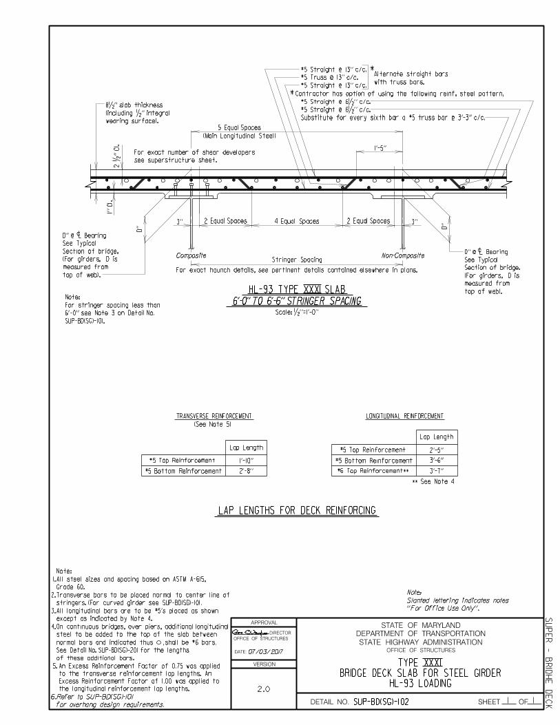
5 Equal Spaces
(Main Longitudinal Steel)
c
4 Equal Spaces
Composite Non-CompositeStringer Spacing
c
*
*
For exact number of shear developers
top of web).
Alternate straight bars
with truss bars.
measured from
see superstructure sheet.
For exact haunch details, see pertinent details contained elsewhere in plans.
Contractor has option of using the following reinf. steel pattern,
See Typical
Section of bridge.
(For girders, D is
2 •'' Cl.
1''
Cl.
D''
D'' @ Bearing
#5 Straight @ 13'' c/c.
#5 Truss @ 13'' c/c.
#5 Straight @ 13'' c/c.
#5 Straight @ 6•'' c/c.
#5 Straight @ 6•'' c/c.
Substitute for every sixth bar a #5 truss bar @ 3'-3'' c/c.
Scale: •''=1'-0''
D''
HL-93 TYPE XXXI SLAB
6'-0'' TO 6'-6'' STRINGER SPACING
1'-5''
2 Equal Spaces 2 Equal Spaces3'' 3''
wearing surface).
(including •'' integral
8•'' slab thickness
top of web).
measured from
(For girders, D is
Section of bridge.
See Typical
D'' @ Bearing
''For Office Use Only''.
Slanted lettering indicates notes
Note:
TRANSVERSE REINFORCEMENT LONGITUDINAL REINFORCEMENT
#5 Top Reinforcement
** See Note 4
(See Note 5)
Lap Length
#5 Bottom Reinforcement
#6 Top Reinforcement**
#5 Top Reinforcement
Lap Length
#5 Bottom Reinforcement
LAP LENGTHS FOR DECK REINFORCING
Grade 60.
All steel sizes and spacing based on ASTM A-615,
Note:
stringers. (For curved girder see SUP-BD(SG)-101.
Transverse bars to be placed normal to center line of
1'-10''
2'-8''
2'-5''
3'-6''
3'-7''
except as indicated by Note 4.
All longitudinal bars are to be #5's placed as shown3.
4. On continuous bridges, over piers, additional longitudinal
steel to be added to the top of the slab between
normal bars and indicated thus ,shall be #6 bars.
See Detail No. SUP-BD(SG)-201 for the lengths
of these additional bars.
the longitudinal reinforcement lap lengths.
Excess Reinforcement Factor of 1.00 was applied to
to the transverse reinforcement lap lengths. An
An Excess Reinforcement Factor of 0.75 was applied 5.
6.Refer to SUP-BD(SG)-101
for overhang design requirements.
2.
1.
HL-93 LOADINGBRIDGE DECK SLAB FOR STEEL GIRDER
TYPE XXXI
2.0
SUP-BD(SG)-102
SUP
ER - B
RID
HE
DE
CK
07/03/2017
SUP-BD(SG)-101.
6'-0'' see Note 3 on Detail No.
For stringer spacing less than
Note:

APPROVAL
DIRECTOR
OFFICE OF STRUCTURES
DATE:
VERSION
STATE HIGHWAY ADMINISTRATION
DEPARTMENT OF TRANSPORTATION
STATE OF MARYLAND
OFFICE OF STRUCTURES
DETAIL NO. SHEET OF1 1
c
Composite
top of web).
measured from
For exact number of shear developers
(Main Longitudinal Steel)
Stringer SpacingNon-Composite
c
measured from
top of web).
*
*
Alternate straight bars
with truss bars.
see superstructure sheet.
For exact haunch details, see pertinent details contained elsewhere in plans.
5 Equal Spaces
Contractor has option of using the following reinf. steel pattern,
See Typical
See Typical
Section of bridge.
Section of bridge.
(For girders, D is
(For girders, D is
#5 Straight @ 12'' c/c.
#5 Truss @ 12'' c/c.
#5 Straight @ 12'' c/c.
#5 Straight @ 6'' c/c.
#5 Straight @ 6'' c/c.
Substitute for every sixth bar a #5 truss bar @ 3'-0'' c/c.2 •'' Cl.
1''
Cl.
D''
D'' @ Bearing
D''
D'' @ Bearing
Scale: •''=1'-0''
HL-93 TYPE XXXII SLAB
GREATER THAN 6'-6'' TO 7'-0'' STRINGER SPACING
3 Equal Spaces
1'-7''
5 Equal Spaces 3 Equal Spaces3'' 3''
wearing surface).
(including •'' integral
8•'' slab thickness
''For Office Use Only''.
Slanted lettering indicates notes
Note:Grade 60.
All steel sizes and spacing based on ASTM A-615,
Note:
stringers. (For curved girder see SUP-BD(SG)-101.
Transverse bars to be placed normal to center line of
except as indicated by Note 4.
All longitudinal bars are to be #5's placed as shown
TRANSVERSE REINFORCEMENT LONGITUDINAL REINFORCEMENT
#5 Top Reinforcement
** See Note 4
(See Note 5)
Lap Length
#5 Bottom Reinforcement
#6 Top Reinforcement**
#5 Top Reinforcement
Lap Length
#5 Bottom Reinforcement
LAP LENGTHS FOR DECK REINFORCING
1'-10''
2'-8''
2'-5''
3'-6''
3'-7''
On continuous bridges, over piers, additional longitudinal
steel to be added to the top of the slab between
normal bars and indicated thus ,shall be #6 bars.
See Detail No. SUP-BD(SG)-201 for the lengths
of these additional bars.
the longitudinal reinforcement lap lengths.
Excess Reinforcement Factor of 1.00 was applied to
to the transverse reinforcement lap lengths. An
An Excess Reinforcement Factor of 0.75 was applied 5.
Refer to SUP-BD(SG)-101
for overhang design requirements.
6.
4.
3.
2.
1.
HL-93 LOADINGBRIDGE DECK SLAB FOR GIRDERS
TYPE XXXII
SUP
ER - B
RID
GE
DE
CKSUP-BD(SG)-103
2.0
07/03/2017

APPROVAL
DIRECTOR
OFFICE OF STRUCTURES
DATE:
VERSION
STATE HIGHWAY ADMINISTRATION
DEPARTMENT OF TRANSPORTATION
STATE OF MARYLAND
OFFICE OF STRUCTURES
DETAIL NO. SHEET OF1 1
Grade 60.
All steel sizes and spacing based on ASTM A-615,
Note:
except as indicated by Note 4.
All longitudinal bars are to be #5's placed as shown
TRANSVERSE REINFORCEMENT LONGITUDINAL REINFORCEMENT
#5 Top Reinforcement
** See Note 4
(See Note 5)
Lap Length
#5 Bottom Reinforcement
#6 Top Reinforcement**
#5 Top Reinforcement
Lap Length
#5 Bottom Reinforcement
LAP LENGTHS FOR DECK REINFORCING
1'-10''
2'-8''
2'-5''
3'-6''
3'-7''
4. On continuous bridges, over piers, additional longitudinal
steel to be added to the top of the slab between
normal bars and indicated thus ,shall be #6 bars.
See Detail No. SUP-BD(SG)-201 for the lengths
of these additional bars.
the longitudinal reinforcement lap lengths.
Excess Reinforcement Factor of 1.00 was applied to
to the transverse reinforcement lap lengths. An
An Excess Reinforcement Factor of 0.75 was applied 5.
6.Refer to SUP-BD(SG)-101
for overhang design requirements.
3.
2.
1.
HL-93 LOADINGBRIDGE DECK SLAB FOR STEEL GIRDERS
TYPE XXXIII
SUP
ER - B
RID
GE
DE
CKSUP-BD(SG)-104
2.0
Stringer SpacingComposite
For exact number of shear developers
wearing surface).
*
*
Alternate straight bars
with truss bars.
(Main Longitudinal Steel)
6 Equal Spaces
5 Equal Spaces
Non-Composite
c
measured from
top of web).
see superstructure sheet.
For exact haunch details, see pertinent details contained elsewhere in plans.
c
measured from
top of web).
Contractor has option of using the following reinf. steel pattern,
See Typical
See Typical
Section of bridge.
Section of bridge.
(For girders, D is
(For girders, D is
(including •'' integral
9'' slab thickness2 •'' Cl.
1''
Cl.
D'' @ Bearing
D''
Scale: •''=1'-0''
#5 Straight @ 12'' c/c.
#5 Truss @ 12'' c/c.
#5 Straight @ 12'' c/c.
#5 Straight @ 6'' c/c.
#5 Straight @ 6'' c/c.
Substitute for every sixth bar a #5 truss bar @ 3'-0'' c/c.
D''
D'' @ Bearing
''For Office Use Only''.
Slanted lettering indicates notes
Note:
HL-93 TYPE XXXIII SLAB
GREATER THAN 7'-0'' TO 7'-6'' STRINGER SPACING
3 Equal Spaces 3 Equal Spaces3'' 3''
1'-9''
07/03/2017
stringers. (For curved girder see SUP-BD(SG)-101).
Transverse bars to be placed normal to center line of

APPROVAL
DIRECTOR
OFFICE OF STRUCTURES
DATE:
VERSION
STATE HIGHWAY ADMINISTRATION
DEPARTMENT OF TRANSPORTATION
STATE OF MARYLAND
OFFICE OF STRUCTURES
DETAIL NO. SHEET OF1 1
Grade 60.
All steel sizes and spacing based on ASTM A-615,
Note:
1.
2.
except as indicated by Note 4.
All longitudinal bars are to be #5's placed as shown3.
TRANSVERSE REINFORCEMENT LONGITUDINAL REINFORCEMENT
#5 Top Reinforcement
** See Note 4
(See Note 5)
Lap Length
#5 Bottom Reinforcement
#6 Top Reinforcement**
#5 Top Reinforcement
Lap Length
#5 Bottom Reinforcement
LAP LENGTHS FOR DECK REINFORCING
1'-10''
2'-8''
2'-5''
3'-6''
3'-7''
4. On continuous bridges, over piers, additional longitudinal
steel to be added to the top of the slab between
normal bars and indicated thus ,shall be #6 bars.
See Detail No. SUP-BD(SG)-201 for the lengths
of these additional bars.
the longitudinal reinforcement lap lengths.
Excess Reinforcement Factor of 1.00 was applied to
to the transverse reinforcement lap lengths. An
An Excess Reinforcement Factor of 0.75 was applied 5.
Refer to SUP-BD(SG)-1016.
for overhang design requirements.
HL-93 LOADINGBRIDGE DECK SLAB FOR STEEL GIRDERS
TYPE XXXIV
SUP
ER - B
RID
GE
DE
CKSUP-BD(SG)-105
2.0
5 Equal Spaces
top of web).
measured from
measured from
top of web).
7 Equal Spaces
see superstructure sheet.
For exact haunch details, see pertinent details contained elsewhere in plans.
Non-Composite
(Main Longitudinal Steel)
*
*
Alternate straight bars
with truss bars.
wearing surface).
For exact number of shear developers
CompositeStringer Spacing
c
c
Contractor has option of using the following reinf. steel pattern,
See Typical
See Typical
Section of bridge.
Section of bridge.
(For girders, D is
(For girders, D is
9'' slab thickness
(including •'' integral2 •'' Cl.
1''
Cl.
D''
D'' @ Bearing
Scale: •''=1'-0''
#5 Straight @ 11'' c/c.
#5 Truss @ 11'' c/c.
#5 Straight @ 11'' c/c.
#5 Straight @ 5•'' c/c.
#5 Straight @ 5•'' c/c.
Substitute for every sixth bar a #5 truss bar @ 2'-9'' c/c.
D''
D'' @ Bearing
''For Office Use Only''.
Slanted lettering indicates notes
Note:
HL-93 TYPE XXXIV SLAB
GREATER THAN 7'-6'' TO 8'-0'' STRINGER SPACING
1'-11''
4 Equal Spaces 4 Equal Spaces3'' 3''
07/03/2017
stringers. (For curved girder see SUP-BD(SG)-101).
Transverse bars to be placed normal to center line of

APPROVAL
DIRECTOR
OFFICE OF STRUCTURES
DATE:
VERSION
STATE HIGHWAY ADMINISTRATION
DEPARTMENT OF TRANSPORTATION
STATE OF MARYLAND
OFFICE OF STRUCTURES
DETAIL NO. SHEET OF1 1
HL-93 LOADINGBRDIGE DECK SLAB FOR STEEL GIRDERS
TYPE XXXV
SUP
ER - B
RID
GE
DE
CKSUP-BD(SG)-106
2.0
wearing surface).
For exact number of shear developers
(Main Longitudinal Steel)
7 Equal Spaces
Composite
c
measured from
top of web).
Stringer Spacing
5 Equal Spaces
*
*
Alternate straight bars
with truss bars.
Non-Composite
c
measured from
top of web).
see superstructure sheet.
For exact haunch details, see pertinent details contained elsewhere in plans.
Contractor has option of using the following reinf. steel pattern,
See Typical
See Typical
Section of bridge.
Section of bridge.
(For girders, D is
(For girders, D is
(including •'' integral
1''
Cl.
2 •'' Cl.
D'' @ Bearing
D''
Scale: •''=1'-0''
D''
D'' @ Bearing
Substitute for every sixth bar a #5 truss bar @ 3'-0'' c/c.
#5 Straight @ 6'' c/c.
#5 Straight @ 12'' c/c.
#5 Truss @ 12'' c/c.
#5 Straight @ 12'' c/c.
9•'' slab thickness#5 Straight @ 6'' c/c.
''For Office Use Only''.
Slanted lettering indicates notes
Note:
HL-93 TYPE XXXV SLAB
GREATER THAN 8'-0'' TO 8'-6'' STRINGER SPACING
2'-0''
3 Equal Spaces 3 Equal Spaces3'' 3''
Grade 60.
All steel sizes and spacing based on ASTM A-615,
Note:
TRANSVERSE REINFORCEMENT LONGITUDINAL REINFORCEMENT
#5 Top Reinforcement
** See Note 4
(See Note 5)
Lap Length
#5 Bottom Reinforcement
#6 Top Reinforcement**
#5 Top Reinforcement
Lap Length
#5 Bottom Reinforcement
LAP LENGTHS FOR DECK REINFORCING
1'-10''
2'-8''
2'-5''
3'-6''
3'-7''
4. On continuous bridges, over piers, additional longitudinal
steel to be added to the top of the slab between
normal bars and indicated thus ,shall be #6 bars.
See Detail No. SUP-BD(SG)-201 for the lengths
of these additional bars.
the longitudinal reinforcement lap lengths.
Excess Reinforcement Factor of 1.00 was applied to
to the transverse reinforcement lap lengths. An
An Excess Reinforcement Factor of 0.75 was applied 5.
Refer to SUP-BD(SG)-1016.
for overhang design requirements.
3.
2.
1.
07/03/2017
except as indicated by Note 4.
All longitudinal bars are to be #5's placed as shown
stringers. (For curved girder see SUP-BD(SG)-101).
Transverse bars to be placed normal to center line of

APPROVAL
DIRECTOR
OFFICE OF STRUCTURES
DATE:
VERSION
STATE HIGHWAY ADMINISTRATION
DEPARTMENT OF TRANSPORTATION
STATE OF MARYLAND
OFFICE OF STRUCTURES
DETAIL NO. SHEET OF1 1
HL-93 LOADINGBRIDGE DECK SLABS FOR STEEL GIRDERS
TYPE XXXVI
S
UP
ER - B
RID
GE
DE
CKSUP-BD(SG)-107
2.0
wearing surface).
Composite
For exact number of shear developers
(Main Longitudinal Steel)
7 Equal Spaces
Stringer Spacing
c
top of web).
measured from
*
*
Alternate straight bars
with truss bars.
Non-Composite
c
measured from
top of web).
see superstructure sheet.
For exact haunch details, see pertinent details contained elsewhere in plans.
Contractor has option of using the following reinf. steel pattern,
See Typical
See Typical
Section of bridge.
Section of bridge.
(For girders, D is
(For girders, D is
9•'' slab thickness
(including •'' integral2 •'' Cl.
1''
Cl.
D''
D'' @ Bearing
Scale: •''=1'-0''
D'' @ Bearing
D''
#5 Straight @ 11'' c/c.
#5 Truss @ 11'' c/c.
#5 Straight @ 5•'' c/c.
#5 Straight @ 5•'' c/c.
Substitute for every sixth bar a #5 truss bar @ 2'-9'' c/c.
2'-1''
''For Office Use Only''.
Slanted lettering indicates notes
Note:
#5 Straight @ 11'' c/c.
HL-93 TYPE XXXVI SLAB
GREATER THAN 8'-6'' TO 9'-0'' STRINGER SPACING
4 Equal Spaces 4 Equal Spaces6 Equal Spaces3'' 3''
Grade 60.
All steel sizes and spacing based on ASTM A-615,
Note:
except as indicated by Note 4.
All longitudinal bars are to be #5's placed as shown
TRANSVERSE REINFORCEMENT LONGITUDINAL REINFORCEMENT
#5 Top Reinforcement
** See Note 4
(See Note 5)
Lap Length
#5 Bottom Reinforcement
#6 Top Reinforcement**
#5 Top Reinforcement
Lap Length
#5 Bottom Reinforcement
LAP LENGTHS FOR DECK REINFORCING
1'-10''
2'-8''
2'-5''
3'-6''
3'-7''
4. On continuous bridges, over piers, additional longitudinal
steel to be added to the top of the slab between
normal bars and indicated thus ,shall be #6 bars.
See Detail No. SUP-BD(SG)-201 for the lengths
of these additional bars.
the longitudinal reinforcement lap lengths.
Excess Reinforcement Factor of 1.00 was applied to
to the transverse reinforcement lap lengths. An
An Excess Reinforcement Factor of 0.75 was applied 5.
Refer to SUP-BD(SG)-1016.
for overhang design requirements.
3.
2.
1.
07/03/2017
stringers. (For curved girder see SUP-BD(SG)-101).
Transverse bars to be placed normal to center line of
APPROVAL
DIRECTOR
OFFICE OF STRUCTURES
DATE:
VERSION
STATE HIGHWAY ADMINISTRATION
DEPARTMENT OF TRANSPORTATION
STATE OF MARYLAND
OFFICE OF STRUCTURES
DETAIL NO. SHEET OF1 1
wearing surface).
Composite
For exact number of shear developers
Stringer Spacing
c
measured from
top of web).
(Main Longitudinal Steel)
7 Equal Spaces
Non-Composite
*
*
Alternate straight bars
with truss bars.
c
measured from
top of web).
see superstructure sheet.
For exact haunch details, see pertinent details contained elsewhere in plans.
Contractor has option of using the following reinf. steel pattern,
See Typical
See Typical
Section of bridge.
Section of bridge.
(For girders, D is
(For girders, D is
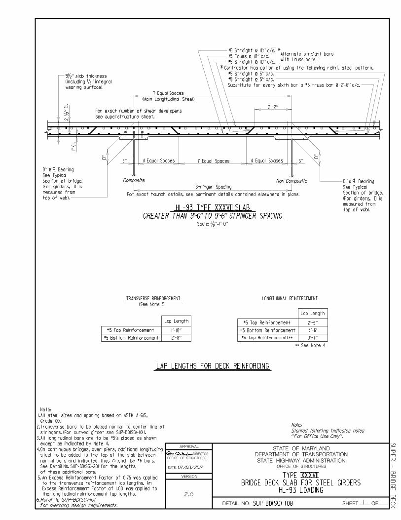
#5 Straight @ 10'' c/c.
#5 Truss @ 10'' c/c.
#5 Straight @ 10'' c/c.
#5 Straight @ 5'' c/c.
#5 Straight @ 5'' c/c.
Substitute for every sixth bar a #5 truss bar @ 2'-6'' c/c.
2 •'' Cl.
9•'' slab thickness
(including •'' integral
1''
Cl.
D'' @ Bearing
D''
Scale: …''=1'-0''
D''
D'' @ Bearing
HL-93 TYPE XXXVII SLAB
2'-2''
7 Equal Spaces4 Equal Spaces 4 Equal Spaces3'' 3''
GREATER THAN 9'-0'' TO 9'-6'' STRINGER SPACING
''For Office Use Only''.
Slanted lettering indicates notes
Note:Grade 60.
All steel sizes and spacing based on ASTM A-615,
Note:
TRANSVERSE REINFORCEMENT LONGITUDINAL REINFORCEMENT
#5 Top Reinforcement
** See Note 4
(See Note 5)
Lap Length
#5 Bottom Reinforcement
#6 Top Reinforcement**
#5 Top Reinforcement
Lap Length
#5 Bottom Reinforcement
LAP LENGTHS FOR DECK REINFORCING
1'-10''
2'-8''
2'-5''
3'-6'
3'-7''
except as indicated by Note 4.
All longitudinal bars are to be #5's placed as shown3.
4. On continuous bridges, over piers, additional longitudinal
steel to be added to the top of the slab between
normal bars and indicated thus ,shall be #6 bars.
See Detail No. SUP-BD(SG)-201 for the lengths
of these additional bars.
the longitudinal reinforcement lap lengths.
Excess Reinforcement Factor of 1.00 was applied to
to the transverse reinforcement lap lengths. An
An Excess Reinforcement Factor of 0.75 was applied 5.
Refer to SUP-BD(SG)-1016.
for overhang design requirements.
2.
1.
HL-93 LOADINGBRIDGE DECK SLAB FOR STEEL GIRDERS
TYPE XXXVII
SUP
ER - B
RID
GE
DE
CKSUP-BD(SG)-108
2.0
07/03/2017
stringers. (For curved girder see SUP-BD(SG)-101).
Transverse bars to be placed normal to center line of

APPROVAL
DIRECTOR
OFFICE OF STRUCTURES
DATE:
VERSION
STATE HIGHWAY ADMINISTRATION
DEPARTMENT OF TRANSPORTATION
STATE OF MARYLAND
OFFICE OF STRUCTURES
DETAIL NO. SHEET OF1 1
''For Office Use Only''.
Slanted lettering indicates notes
Note:
wearing surface).
c
top of web).
measured from
Composite
For exact number of shear developers
7 Equal Spaces
Stringer Spacing
(Main Longitudinal Steel)
8 Equal Spaces
Non-Composite
c
measured from
top of web).
*
*
Alternate straight bars
with truss bars.
see superstructure sheet.
For exact haunch details, see pertinent details contained elsewhere in plans.
Contractor has option of using the following reinf. steel pattern,
See Typical
See Typical
(For girders, D is
(For girders, D is
Section of bridge.
Section of bridge.
#5 Straight @ 10'' c/c.
#5 Truss @ 10'' c/c.
#5 Straight @ 10'' c/c.
#5 Straight @ 5'' c/c.
#5 Straight @ 5'' c/c.
Substitute for every sixth bar a #5 truss bar @ 2'-6'' c/c.2 •'' Cl.
10'' slab thickness
(including •'' integral
1''
Cl.
D''
D'' @ Bearing
D''
D'' @ Bearing
Scale: …''=1'-0''
HL-93 TYPE XXXVIII SLAB
5 Equal Spaces 5 Equal Spaces
2'-4''
3'' 3''
GREATER THAN 9'-6'' TO 10'-0'' STRINGER SPACING
Grade 60.
All steel sizes and spacing based on ASTM A-615,
Note:
except as indicated by Note 4.
All longitudinal bars are to be #5's placed as shown
TRANSVERSE REINFORCEMENT LONGITUDINAL REINFORCEMENT
#5 Top Reinforcement
** See Note 4
(See Note 5)
Lap Length
#5 Bottom Reinforcement
#6 Top Reinforcement**
#5 Top Reinforcement
Lap Length
#5 Bottom Reinforcement
LAP LENGTHS FOR DECK REINFORCING
1'-10''
2'-8''
2'-5''
3'-6''
3'-7''
4. On continuous bridges, over piers, additional longitudinal
steel to be added to the top of the slab between
normal bars and indicated thus ,shall be #6 bars.
See Detail No. SUP-BD(SG)-201 for the lengths
of these additional bars.
the longitudinal reinforcement lap lengths.
Excess Reinforcement Factor of 1.00 was applied to
to the transverse reinforcement lap lengths. An
An Excess Reinforcement Factor of 0.75 was applied 5.
Refer to SUP-BD(SG)-1016.
for overhang design requirements.
3.
2.
1.
HL-93 LOADINGBRIDGE DECK SLAB FOR STEEL GIRDERS
TYPE XXXVIII
SUP
ER - B
RID
GE
DE
CKSUP-BD(SG)-109
2.0
07/03/2017
stringers. (For curved girder see SUP-BD(SG)-101).
Transverse bars to be placed normal to center line of
APPROVAL
DIRECTOR
OFFICE OF STRUCTURES
DATE:
VERSION
STATE HIGHWAY ADMINISTRATION
DEPARTMENT OF TRANSPORTATION
STATE OF MARYLAND
OFFICE OF STRUCTURES
DETAIL NO. SHEET OF1 1
wearing surface).
For exact number of shear developers
Composite
Stringer Spacing
8 Equal Spaces
(Main Longitudinal Steel)
Non-Composite
*
*
Alternate straight bars
with truss bars.
c
measured from
top of web).
c
measured from
top of web).
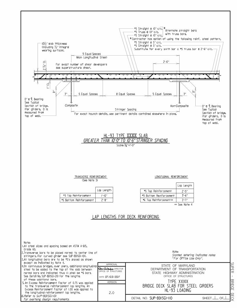
9 Equal Spaces
see superstructure sheet.
For exact haunch details, see pertinent details contained elsewhere in plans.
See Typical
See Typical
Section of bridge.
Section of bridge.
Contractor has option of using the following reinf. steel pattern,
(For girders, D is
(For girders, D is
10•'' slab thickness
(including •'' integral
#5 Straight @ 10'' c/c.
#5 Truss @ 10'' c/c.
#5 Straight @ 10'' c/c.
#5 Straight @ 5'' c/c.
#5 Straight @ 5'' c/c.
Substitute for every sixth bar a #5 truss bar @ 2'-6'' c/c.
2 •'' Cl.
1''
Cl.
D'' @ Bearing
D''
Scale: …''=1'-0''
D''
D'' @ Bearing
HL-93 TYPE XXXIX SLAB
GREATER THAN 10'-0'' TO 10'-6'' STRINGER SPACING
2'-6''
5 Equal Spaces 5 Equal Spaces3'' 3''
''For Office Use Only''.
Slanted lettering indicates notes
Note:Grade 60.
All steel sizes and spacing based on ASTM A-615,
Note:
1.
2.
3.
TRANSVERSE REINFORCEMENT LONGITUDINAL REINFORCEMENT
#5 Top Reinforcement
** See Note 4
(See Note 5)
Lap Length
#5 Bottom Reinforcement
#6 Top Reinforcement**
#5 Top Reinforcement
Lap Length
#5 Bottom Reinforcement
LAP LENGTHS FOR DECK REINFORCING
1'-10''
2'-8''
2'-5''
3'-6''
3'-7''
4. On continuous bridges, over piers, additional longitudinal
steel to be added to the top of the slab between
normal bars and indicated thus ,shall be #6 bars.
See Detail No. SUP-BD(SG)-201 for the lengths
of these additional bars.
the longitudinal reinforcement lap lengths.
Excess Reinforcement Factor of 1.00 was applied to
to the transverse reinforcement lap lengths. An
An Excess Reinforcement Factor of 0.75 was applied 5.
6.Refer to SUP-BD(SG)-101
for overhang design requirements.
HL-93 LOADINGBRIDGE DECK SLAB FOR STEEL GIRDERS
TYPE XXXIX
SUP
ER - B
RID
GE
DE
CKSUP-BD(SG)-110
2.0
07/03/2017
except as indicated by Note 4.
All longitudinal bars are to be #5's placed as shown
stringers. (For curved girder see SUP-BD(SG)-101).
Transverse bars to be placed normal to center line of
APPROVAL
DIRECTOR
OFFICE OF STRUCTURES
DATE:
VERSION
STATE HIGHWAY ADMINISTRATION
DEPARTMENT OF TRANSPORTATION
STATE OF MARYLAND
OFFICE OF STRUCTURES
DETAIL NO. SHEET OF1 1
DECK SLABS OVER PIERS FOR STEEL GIRDERSREINFORCING IN TOP OF CONTINUOUS
ADDITIONAL LONGITUDINAL
SUP
ER - B
RID
GE
DE
CKSUP-BD(SG)-201
1.0
c
c
c
c c
c
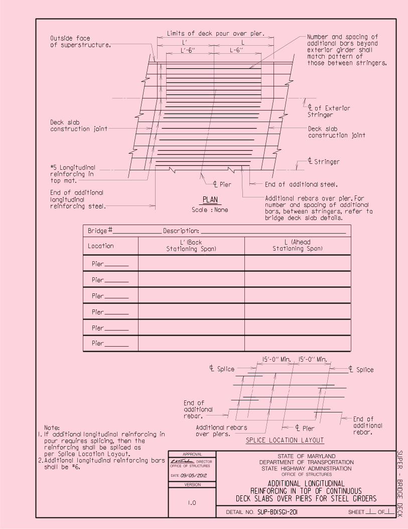
PLAN
L'
L'-6''
Stringer
Pier
Scale : None
Limits of deck pour over pier.
End of additional
Note:
Deck slab
construction joint
#5 Longitudinal
reinforcing in
top mat.
longitudinal
reinforcing steel.
Additional rebars over pier. For
number and spacing of additional
bars, between stringers, refer to
construction joint
Location
Splice Splice
Pier
SPLICE LOCATION LAYOUTIf additional longitudinal reinforcing in
pour requires splicing, then the
15'-0'' Min. 15'-0'' Min.
Bridge Description:#
Pier
Pier
Pier
Pier
Pier
Pier
End of
additional
rebar.
Additional rebars
over piers.
End of
additional
rebar.
End of additional steel.
Deck slab
L-6''
L
Stationing Span)
L' (BackStationing Span)
L (Ahead
Stringer
of Exterior
of superstructure.
Outside face
those between stringers.
match pattern of
exterior girder shall
additional bars beyond
Number and spacing of
2.
1.
shall be #6.
Additional longitudinal reinforcing bars
per Splice Location Layout.
reinforcing shall be spliced as
09/05/2012
bridge deck slab details.

APPROVAL
DIRECTOR
OFFICE OF STRUCTURES
DATE:
VERSION
STATE HIGHWAY ADMINISTRATION
DEPARTMENT OF TRANSPORTATION
STATE OF MARYLAND
OFFICE OF STRUCTURES
DETAIL NO. SHEET OF1 1
FOR 42'' F-SHAPECONCRETE BRIDGE DECK OVERHANG
ADDITIONAL REINFORCING FOR
SUP
ER - B
RID
GE
DE
CKSUP-BD(SG)-202
PLAN
Scale: …'' = 1'-0''
deckedge ofOutside
Stringer spacing Overhang
bars (typ.)
reinforcing
Additional ''L1''
''L2''
L 1st interior girder
L exterior girder
c
c
reinforcing (typ.)
Normal deck slab
Bar Size
Additional''L1'' ''L2''
Overhang
Maximum
XXXI
XXXII
XXXIII
XXXIV
XXXV
XXXVI
XXXVII
XXXVIII
XXXIX
#6
#6
#6
#6
#5
#5
#5
#5
4'-7''
4'-7''
6'-10'' 4'-0''
4'-4•''
4'-8‚''
5'-0''
5'-3ƒ''
5'-7•''
5'-11‚''
6'-0''
6'-0''
4'-8•'' 7'-0''
4'-9'' 7'-0''
#5 4'-7''
5'-1‚'' 7'-4‚''
4'-10…'' 4'-10…''
4'-8‚'' 4'-8‚''
4'-6'' 4'-6''
4'-3„'' 4'-3„''
1.
2.
Notes:
Additional reinforcing to be placed
in top mat of deck.
Deck overhangs greater than shown
will need to be designed.
3.
deck reinforcing.
Bundle additional bar with normal
Deck Type
1.00
08/16/2019
DRAFT
APPROVAL
DIRECTOR
OFFICE OF STRUCTURES
DATE:
VERSION
STATE HIGHWAY ADMINISTRATION
DEPARTMENT OF TRANSPORTATION
STATE OF MARYLAND
OFFICE OF STRUCTURES
DETAIL NO. SHEET OF1 1
DRAFTFOR THREE STRAND STRUCTURAL TUBE RAIL
CONCRETE BRIDGE DECK OVERHANGADDITIONAL REINFORCING FOR
SUP
ER - B
RID
GE
DE
CKSUP-BD(SG)-203
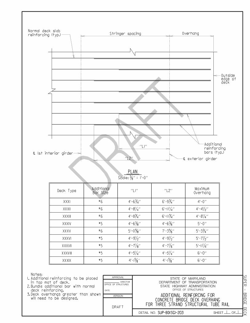
PLAN
Scale: …'' = 1'-0''
deckedge ofOutside
Stringer spacing Overhang
bars (typ.)
reinforcing
Additional ''L1''
''L2''
L 1st interior girder
L exterior girder
c
c
reinforcing (typ.)
Normal deck slab
Bar Size
Additional''L1'' ''L2''
Overhang
Maximum
XXXI
XXXII
XXXIII
XXXIV
XXXV
XXXVI
XXXVII
XXXVIII
XXXIX
#6
#6
#6
#6
#5
#5
#5
#5
4'-0''
4'-4•''
4'-8‚''
5'-0''
5'-3ƒ''
5'-7•''
5'-11‚''
6'-0''
6'-0''
#5
4'-6ƒ'' 6'-9ƒ''
4'-8‚'' 6'-11‚''
4'-8ƒ'' 6'-11ƒ''
4'-6…'' 4'-6…''
7'-3†''5'-0†''
4'-9•'' 4'-9•''
4'-7„'' 4'-7„''
4'-5‚'' 4'-5‚''
4'-1†'' 4'-1†''
1.
2.
Notes:
Additional reinforcing to be placed
in top mat of deck.
Deck overhangs greater than shown
will need to be designed.
3.
deck reinforcing.
Bundle additional bar with normal
Deck Type

DRAFT
APPROVAL
DIRECTOR
OFFICE OF STRUCTURES
DATE:
VERSION
STATE HIGHWAY ADMINISTRATION
DEPARTMENT OF TRANSPORTATION
STATE OF MARYLAND
OFFICE OF STRUCTURES
DETAIL NO. SHEET OF1 1
DRAFTFOR PARAPER WITH SIDEWALK
CONCRETE BRIDGE DECK OVERHANGADDITIONAL REINFORCING FOR
SUP
ER - B
RID
GE
DE
CKSUP-BD(SG)-204
PLAN
Scale: …'' = 1'-0''
deckedge ofOutside
Stringer spacing Overhang
bars (typ.)
reinforcing
Additional
L 1st interior girder
L exterior girder
c
c
reinforcing (typ.)
Normal deck slab
Bar Size
Additional
Overhang
Maximum
XXXI
XXXII
XXXIII
XXXIV
XXXV
XXXVI
XXXVII
XXXVIII
XXXIX
#5
#5
#5
#5
4'-0''
4'-4•''
4'-8‚''
5'-0''
5'-3ƒ''
5'-7•''
5'-11‚''
6'-0''
6'-0''
#5
''L''
''L''
each bar
every other
every other
every other
every other
every third
every fourth
every fifth
every sixth
Reinforcing
Main Deck
Bundle with
#5
#5
#5
#5
3'-0''
3'-0''
2'-10ƒ''
2'-8‚''
3'-1„''
2'-10''
2'-5†''
1'-10•''
2'-0…''
1.
2.
3.
Notes:
Additional reinforcing to be placed
in top mat of deck.
Deck overhangs greater than shown
will need to be designed.
deck reinforcing.
Bundle additional bar with normal
Deck Type

APPROVAL
DIRECTOR
OFFICE OF STRUCTURES
DATE:
VERSION
STATE HIGHWAY ADMINISTRATION
DEPARTMENT OF TRANSPORTATION
STATE OF MARYLAND
OFFICE OF STRUCTURES
DETAIL NO. SHEET OF1 4
SUP
ER - B
RID
GE
DE
CKSUP-BD(SG)-301
(Ty
pic
al)
Stiffe
ner
Width
A
*6'' x 4'' x ƒ''
Seat
Angle/
Plate
3ƒ'' cl.
2'' cl.
L Strin
ger
c
L Strin
ger
c
2'-0''
2'' cl.
c
Scale:
…'' = 1'-0''
''Ty
pic
al
Cross
Sectio
n'' of
brid
ge
overhang and parapet see
For e
xact co
nfig
uratio
n of
L of
bearin
g
perpe
ndic
ular to
#5
@ 9'' - pla
ce
L
A
over back
wall)
and 3 co
ntin
uo
us
bet
wee
n bea
ms
bars (3 bars
6-#5 straig
ht
EL
EV
ATIO
N
AT
BRID
GE S
EA
T
AR
EA
OV
ER
BE
AM
S
chee
kwall
To
p of
at abut
me
nt
Brid
ge seat
c bearin
g
perpe
ndic
ular to
#5
@ 9'' m
ax. - pla
ce
brid
ge road
way
To
p of
clear
1'' min.
B
B
not shown for clarity.
Normal deck reinforcing
Note:Notes:
* Longest leg of angle shall be
increased as necessary so that
angle exceeds stiffener width by at
least •''. In lieu of the seat angle
a ƒ'' plate may be used. The plate
shall be a minimum of 6'' wide and
shall exceed stiffener width by at
least •''.
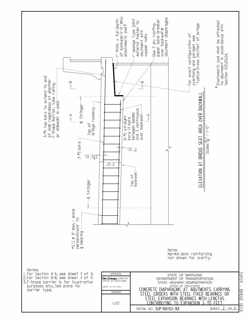
For Section B-B, see sheet 4 of 4.
For Section A-A, see sheet 3 of 4.
2.
1.
3.
4.
barrier type.
purposes only. See plans for
F-Shape barrier is for illustrative
CONTRIBUTING TO EXPANSION 70 FEETSTEEL EXPANSION BEARINGS WITH LENGTHS
STEEL GIRDERS WITH STEEL FIXED BEARINGS ORCONCRETE DIAPHRAGMS AT ABUTMENTS CARRYING
<1.02
07/25/2019
APPROVAL
DIRECTOR
OFFICE OF STRUCTURES
DATE:
VERSION
STATE HIGHWAY ADMINISTRATION
DEPARTMENT OF TRANSPORTATION
STATE OF MARYLAND
OFFICE OF STRUCTURES
DETAIL NO. SHEET OF2 4
SUP
ER - B
RID
GE
DE
CKSUP-BD(SG)-301
A
3ƒ'' cl.
L Strin
ger
c
L Strin
ger
c
2'-0''
2'' cl.
Scale:
…'' = 1'-0''
or sid
ewalk is use
d
F-Shape
Barrier, tube railin
g,
of sla
b re
gardle
ss of
whether
3-#5 to
p bars to e
xte
nd to e
nd
back
wall
To
p of
L
A
over back
wall)
and 3 co
ntin
uo
us
bet
wee
n bea
ms
bars (3 bars
6-#5 straig
ht
3-#5 bars
c bearin
g
perpe
ndic
ular to
#5
@ 9'' m
ax. - pla
ce
EL
EV
ATIO
N
AT
BRID
GE S
EA
T
AR
EA
OV
ER
BA
CK
WA
LL
abut
me
nt dia
phrag
ms
over back
wall @
paper bo
nd breaker
Use
2 ply ro
ofin
g
co
pper nails
abut
me
nt
wit
h
material f
aste
n to
1'' spo
nge ty
pe joint
ela
sto
meric pad
of
back
wall (1'-0'' min.)
1'' thic
k
x f
ull d
epth
brid
ge road
way
To
p of
*
Sectio
n 432.0
3.0
4.
to abut
me
nt in accordance
wit
h
Ela
sto
meric pad shall
be attache
d
''Ty
pic
al
Cross
Sectio
n'' of
brid
ge
overhang and parapet see
For e
xact co
nfig
uratio
n of
*
B
B
not shown for clarity.
Normal deck reinforcing
Note:
For Section B-B, see sheet 4 of 4.
For Section A-A, see sheet 3 of 4.
Notes:
2.
1.
3.
barrier type.
purposes only. See plans for
F-Shape barrier is for illustrative
CONTRIBUTING TO EXPANSION 70 FEETSTEEL EXPANSION BEARINGS WITH LENGTHS
STEEL GIRDERS WITH STEEL FIXED BEARINGS ORCONCRETE DIAPHRAGMS AT ABUTMENTS CARRYING
< 1.02
07/25/2019

APPROVAL
DIRECTOR
OFFICE OF STRUCTURES
DATE:
VERSION
STATE HIGHWAY ADMINISTRATION
DEPARTMENT OF TRANSPORTATION
STATE OF MARYLAND
OFFICE OF STRUCTURES
DETAIL NO. SHEET OF3 4
CONTRIBUTING TO EXPANSION < 70 FEETSTEEL EXPANSION BEARINGS WITH LENGTHS
STEEL GIRDERS WITH STEEL FIXED BEARINGS ORCONCRETE DIAPHRAGMS AT ABUTMENTS CARRYING
SUP
ER - B
RID
GE
DE
CKSUP-BD(SG)-301
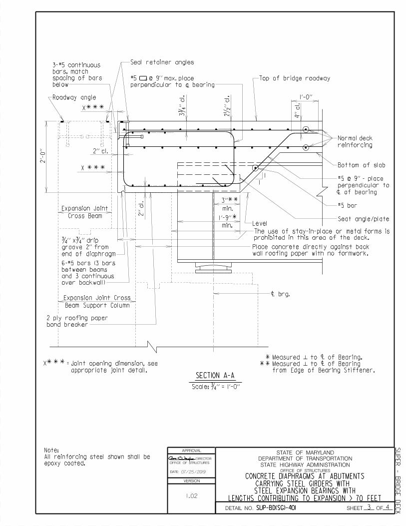
SECTION A-A
1'-0''
4'' cl.
2•'' cl.
1
1
Level
c
c
c
c brg.
2'' cl.
2'' cl.
Scale: ƒ'' = 1'-0''
2'-
0''
3ƒ'' cl.
ƒ'' x ƒ'' drip
groove 2'' from end
of diaphragm, see
detail this sheet
Scale: 3'' = 1'-0''
DRIP GROOVE DETAIL
over backwall)
and 3 continuous
between beams
6-#5 bars (3 bars
paper bond breaker
2 ply roofing
prohibited in this area of the deck
The use of stay-in-place or metal forms is
Seat angle/plate
#5 bar
L of bearing
perpendicular to
#5 @ 9'' - place
Bottom of slab
reinforcing
Normal deck
wall roofing paper with no formwork.
Place concrete directly against back
All reinforcing steel shown shall be
epoxy coated.
Note:
**min.
3''
1'-9''
min.*
***
Roadway angle L
Top of bridge roadway
6''
2'' ƒ'' (typ.)
ƒ''
bearing
perpendicular to c
#5 @ 9'' max. place
of bars below
bars, match spacing
3-#5 continuous
from edge of bearing stiffener.
Measured to of bearing
Measured to of bearing.
1.02
07/25/2019

APPROVAL
DIRECTOR
OFFICE OF STRUCTURES
DATE:
VERSION
STATE HIGHWAY ADMINISTRATION
DEPARTMENT OF TRANSPORTATION
STATE OF MARYLAND
OFFICE OF STRUCTURES
DETAIL NO. SHEET OF4 4
LENGTHS CONTRIBUTING TO EXPANSION < 70 FEETBEARINGS OR STEEL EXPANSION BEARINGS WITH
CARRYING STEEL GIRDERS WITH STEEL FIXEDCONCRETE DIAPHRAGMS AT ABUTMENTS
SUP
ER - B
RID
GE
DE
CKSUP-BD(SG)-301
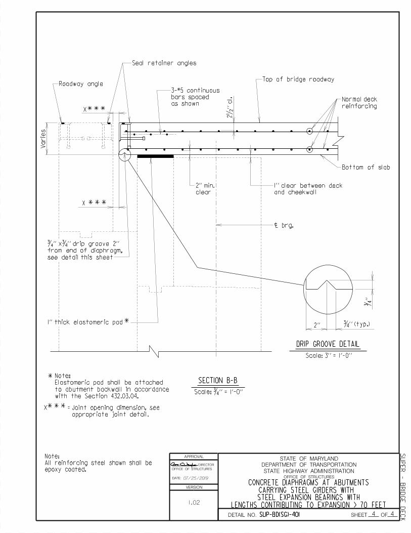
SECTION B-B
2•'' cl.
c brg.
Scale: ƒ'' = 1'-0''
Normal deck
reinforcing
Bottom of slab
ƒ'' xƒ'' drip groove 2''
from end of diaphragm,
see detail this sheet
Scale: 3'' = 1'-0''
DRIP GROOVE DETAIL
1'' thick elastomeric pad
and cheekwall
1'' clear between deck
clear
2'' min.
6''
Note:
epoxy coated.
All reinforcing steel shown shall be
*
Top of bridge roadway
2'' ƒ'' (typ.)
ƒ''
3-#5 continuous
bars spaced
as shown
Note:
Elastomeric pad shall be attached
to abutment backwall in accordance
with the Section 432.03.04.
Roadway angle
1.02
07/25/2019

(Ty
pic
al)
Stiffe
ner
Width
A
*6'' x 4'' x ƒ''
Seat
Angle/
Plate
A
3ƒ'' cl.
2'' cl.
DATE:
STATE HIGHWAY ADMINISTRATION
DEPARTMENT OF TRANSPORTATION
STATE OF MARYLAND
SHEET OF
APPROVAL
*
1 4
OFFICE OF STRUCTURES
DIRECTOR
OFFICE OF STRUCTURES
L Strin
ger
c
L Strin
ger
c
2'-0''
2'' cl.
c
Scale:
…'' = 1'-0''
L
To
p of
chee
k
wall
Brid
ge seat
at abut
me
nt
EL
EV
ATIO
N
AT
BRID
GE S
EA
T
AR
EA
OV
ER
BE
AM
S
CONCRETE DIAPHRAGMS AT ABUTMENTSCARRYING STEEL GIRDERS WITH STEEL EXPANSION BEARINGS WITH
LENGTHS CONTRIBUTING TO EXPANSION > 70 FEET
B
B
Notes:
For Section A-A see Sheet 3 of 4.
For Section B-B see Sheet 4 of 4.
Longest leg of angle shall be
increased as necessary so that
angle exceeds stiffener width by at
least •''. In lieu of the seat angle
a ƒ'' plate may be used. The plate
shall be a minimum of 6'' wide and
shall exceed stiffener width by at
least •''.
1'' min.
clear
SUP-BD(SG)-401
SUP
ER - B
RID
GE
DE
CK
''Ty
pic
al
Cross
Sectio
n'' of
brid
ge
overhang and parapet see
For e
xact co
nfig
uratio
n of
not shown for clarity.
Normal deck reinforcing
Note:
L of
bearin
g
perpe
ndic
ular to
#5
@ 9'' - pla
ce
over back
wall)
and 3 co
ntin
uo
us
bet
wee
n bea
ms
bars (3 bars
6-#5 straig
ht
c bearin
g
perpe
ndic
ular to
#5
@ 9'' m
ax. - pla
ce
3.
2.
1.
road
way
To
p of
brid
ge
1.02
VERSION
DETAIL NO.
4.
barrier type.
purposes only. See plans for
F-Shape barrier is for illustrative
07/25/2019

A
3ƒ'' cl.
DATE:
STATE HIGHWAY ADMINISTRATION
DEPARTMENT OF TRANSPORTATION
STATE OF MARYLAND
SHEET OF
APPROVAL
2 4
OFFICE OF STRUCTURES
DIRECTOR
OFFICE OF STRUCTURES
L Strin
ger
c
L Strin
ger
c
2'-0''
2'' cl.
Scale:
…'' = 1'-0''
L
3-#5 bars
A
*
*
CONCRETE DIAPHRAGMS AT ABUTMENTSCARRYING STEEL GIRDERS WITH STEEL EXPANSION BEARINGS WITH
LENGTHS CONTRIBUTING TO EXPANSION > 70 FEET
EL
EV
ATIO
N
AT
BRID
GE S
EA
T
AR
EA
OV
ER
BA
CK
WA
LL
B
B
Notes:
For Section A-A see Sheet 3 of 4.
For Section B-B see Sheet 4 of 4.1.
2.
SUP-BD(SG)-401
SUP
ER - B
RD
GE
DE
CK
or sid
ewalk is use
d
F-Shape
Barrier, tube railin
g,
of sla
b re
gardle
ss of
whether
3-#5 to
p bars to e
xte
nd to e
nd
not shown for clarity.
Normal deck reinforcing
Note:
''Ty
pic
al
Cross
Sectio
n'' of
brid
ge
overhang and parapet see
For e
xact co
nfig
uratio
n of
over back
wall)
and 3 co
ntin
uo
us
bet
wee
n bea
ms
bars (3 bars
6-#5 straig
ht
c bearin
g
perpe
ndic
ular to
#5
@ 9'' m
ax. - pla
ce
abut
me
nt dia
phrag
ms
over back
wall @
paper bo
nd breaker
Use
2 ply ro
ofin
g
co
pper nails
abut
me
nt
wit
h
material f
aste
n to
1'' spo
nge ty
pe joint
min.) ela
sto
meric pad
of
back
wall (1'-0''
1'' thic
k
x f
ull d
epth
road
way
To
p of
brid
ge
accordance
wit
h the
Sectio
n 432.0
3.0
4.
to abut
me
nt back
wall in
Ela
sto
meric pad shall
be attache
d
Note:
back
wall
To
p of
1.02
VERSION
DETAIL NO.
3.
barrier type.
purposes only. See plans for
F-Shapes barrier is for illustrative
07/25/2019
A
3ƒ'' cl.
DATE:
STATE HIGHWAY ADMINISTRATION
DEPARTMENT OF TRANSPORTATION
STATE OF MARYLAND
SHEET OF
APPROVAL
2 4
OFFICE OF STRUCTURES
DIRECTOR
OFFICE OF STRUCTURES
L Strin
ger
c
L Strin
ger
c
2'-0''
2'' cl.
Scale:
…'' = 1'-0''
L
3-#5 bars
A
*
*
CONCRETE DIAPHRAGMS AT ABUTMENTSCARRYING STEEL GIRDERS WITH STEEL EXPANSION BEARINGS WITH
LENGTHS CONTRIBUTING TO EXPANSION > 70 FEET
EL
EV
ATIO
N
AT
BRID
GE S
EA
T
AR
EA
OV
ER
BA
CK
WA
LL
B
B
Notes:
For Section A-A see Sheet 3 of 4.
For Section B-B see Sheet 4 of 4.1.
2.
SUP-BD(SG)-401
SUP
ER - B
RD
GE
DE
CK
or sid
ewalk is use
d
F-Shape
Barrier, tube railin
g,
of sla
b re
gardle
ss of
whether
3-#5 to
p bars to e
xte
nd to e
nd
not shown for clarity.
Normal deck reinforcing
Note:
''Ty
pic
al
Cross
Sectio
n'' of
brid
ge
overhang and parapet see
For e
xact co
nfig
uratio
n of
over back
wall)
and 3 co
ntin
uo
us
bet
wee
n bea
ms
bars (3 bars
6-#5 straig
ht
c bearin
g
perpe
ndic
ular to
#5
@ 9'' m
ax. - pla
ce
abut
me
nt dia
phrag
ms
over back
wall @
paper bo
nd breaker
Use
2 ply ro
ofin
g
co
pper nails
abut
me
nt
wit
h
material f
aste
n to
1'' spo
nge ty
pe joint
min.) ela
sto
meric pad
of
back
wall (1'-0''
1'' thic
k
x f
ull d
epth
road
way
To
p of
brid
ge
accordance
wit
h the
Sectio
n 432.0
3.0
4.
to abut
me
nt back
wall in
Ela
sto
meric pad shall
be attache
d
Note:
back
wall
To
p of
1.02
VERSION
DETAIL NO.
3.
barrier type.
purposes only. See plans for
F-Shapes barrier is for illustrative
07/25/2019
Note:
SECTION A-A
3
DATE:
STATE HIGHWAY ADMINISTRATION
DEPARTMENT OF TRANSPORTATION
STATE OF MARYLAND
SHEET OF
APPROVAL
OFFICE OF STRUCTURES
DIRECTOR
OFFICE OF STRUCTURES
1'-0''
4'' cl.
2•'' cl.
1
1
Level
**min.
3''
1'-9''
min.
*
c
c***
c
c brg.
2'' cl.
2'' cl.
Scale: ƒ'' = 1'-0''
2'-
0''
X
***X =
***
X***
L
3ƒ'' cl.
epoxy coated.
All reinforcing steel shown shall be
CONCRETE DIAPHRAGMS AT ABUTMENTSCARRYING STEEL GIRDERS WITH STEEL EXPANSION BEARINGS WITH
LENGTHS CONTRIBUTING TO EXPANSION > 70 FEET
4
Top of bridge roadway
ƒ'' xƒ'' drip
groove 2'' from
end of diaphragm
Expansion Joint
Cross Beam
Expansion Joint Cross
Beam Support Column
Joint opening dimension, see
SUP-BD(SG)-401
SUP
ER - B
RID
GE
DE
CK
appropriate joint detail.
over backwall)
and 3 continuous
between beams
6-#5 bars (3 bars
perpendicular to c bearing
#5 @ 9'' max. place
bond breaker
2 ply roofing paper
Roadway angle
below
spacing of bars
bars, match
3-#5 continuous
from Edge of Bearing Stiffener.
Measured to of Bearing
Measured to of Bearing.
Seal retainer angles
wall roofing paper with no formwork.
Place concrete directly against back
Seat angle/plate
#5 bar
L of bearing
perpendicular to
#5 @ 9'' - place
Bottom of slab
reinforcing
Normal deck
prohibited in this area of the deck.
The use of stay-in-place or metal forms is
1.02
VERSION
DETAIL NO.
07/25/2019
Note:
SECTION B-B
4
DATE:
STATE HIGHWAY ADMINISTRATION
DEPARTMENT OF TRANSPORTATION
STATE OF MARYLAND
SHEET OF
APPROVAL
OFFICE OF STRUCTURES
DIRECTOR
OFFICE OF STRUCTURES
2•'' cl.
c brg.
Scale: ƒ'' = 1'-0''
Varie
s
X
***X =
***
X***Normal deck
reinforcing
Bottom of slab
epoxy coated.
All reinforcing steel shown shall be
CONCRETE DIAPHRAGMS AT ABUTMENTSCARRYING STEEL GIRDERS WITH STEEL EXPANSION BEARINGS WITH
LENGTHS CONTRIBUTING TO EXPANSION > 70 FEET
4
*
Roadway angleTop of bridge roadway
ƒ'' xƒ'' drip groove 2''
from end of diaphragm,
see detail this sheet
2'' ƒ'' (typ.)
ƒ''
Scale: 3'' = 1'-0''
DRIP GROOVE DETAIL
3-#5 continuous
bars spaced
as shown
Note:
Elastomeric pad shall be attached
to abutment backwall in accordance
with the Section 432.03.04.
Joint opening dimension, see
SUP-BD(SG)-401
SUP
ER - B
RID
GE
DE
CK
appropriate joint detail.
1'' thick elastomeric pad
and cheekwall
1'' clear between deck
clear
2'' min.
Seal retainer angles
1.02
VERSION
DETAIL NO.
07/25/2019

APPROVAL
DIRECTOR
OFFICE OF STRUCTURES
DATE:
VERSION
STATE HIGHWAY ADMINISTRATION
DEPARTMENT OF TRANSPORTATION
STATE OF MARYLAND
OFFICE OF STRUCTURES
DETAIL NO. SHEET OF1 2
RE-BARS ALIGNED WITH TROUGHFOR CONCRETE SLABS ON STEEL STRINGERS
STEEL FORMS WHICH REMAIN IN PLACE
SUP
ER - B
RID
GE
DE
CKSUP-BD(SG)-501
1.0
Top of Slab
4'-0'' Max. Spacing
Upper (Height > 3'')
Co
ncrete
Deck
Sla
b
De
pth
Height
1''
Continuous High Chair
(Height < 3'')
Slab Bolster Upper
a a
Main Reinforcing Steel Bars.
1''cl.
min.
1'' cl. min.
…''
Support Angle
Intermittent Angle
Haunch Angle
1'' Minimum
Bearing
Caulking
1'' Minimum
Bearing
1•''
min.
1•'' min.
WHERE FORM IS BELOW
BOTTOM OF FLANGE
AND THERE ARE NO
SHEAR CONNECTORS
Alternate attachments will be
considered, that provide the 1•''
Note:
BOTTOM OF FLANGE
AND THERE ARE NO
SHEAR CONNECTORS
WHERE FORM IS ABOVE
concrete encasement of top flange.
Steel
Reinforcing
Distribution
remain in place.
Steel forms which
4'-0'' Max. Spacing
#3 Bar @
Notes:
Permanent steel deck forms and supports shall
distance between beam and/or girder flanges
less two (2) inches.
No welding of these forms to parts carrying
tension will be permitted. These forms shall be
as required.
Any permanently exposed form metal where the
galvanized coating has been damaged shall be
thoroughly cleaned, wire brushed and painted
with two coats of zinc-oxide dust primer, Federal
Specification TT-P-641d, Type II, no color added,
to the satisfaction of the engineer. Minor heat
discoloration in areas of welds need not be
touched up.
Contractor has option of using this detail or
that shown on 2 of 2, except for bridge decks
with curved stringers or bridge with a flared
1.
2.
3.
4.
SECTION
Scale: None
vertically adjusted to attain line and grade
conform to 909.11. Design Span shall be the clear
Supports for rebar shall be provided
by Contractor.
Where shear connectors are utilized,
normal manufacturers detailing may be
utilized at stringer flange.
rebar pattern. For bridge with curved
stringers or bridge with a flared
rebar pattern only the detail shown
on sheet 2 of 2 can be used.
5.
6.
10/18/2011

APPROVAL
DIRECTOR
OFFICE OF STRUCTURES
DATE:
VERSION
STATE HIGHWAY ADMINISTRATION
DEPARTMENT OF TRANSPORTATION
STATE OF MARYLAND
OFFICE OF STRUCTURES
DETAIL NO. SHEET OF2 2
RE-BARS INDEPENDENT WITH TROUGHFOR CONCRETE SLABS ON STEEL STRINGERS
STEEL FORMS WHICH REMAIN IN PLACE
SUP
ER - B
RID
GE
DE
CKSUP-BD(SG)-501
1.0
Top of Slab
4'-0'' Max. Spacing
Upper (Height > 3'')
Co
ncrete
Deck
Sla
b
De
pth
Height
Continuous High Chair
(Height < 3'')
Slab Bolster Upper
Main Reinforcing Steel Bars.1'' cl.
Steel
Reinforcing
Distribution
remain in place.
Steel forms which
@ 4'-0'' Max. Spacing
1'' Slab Bolster Upper
SECTION
Scale: None
Notes:
For notes see sheet 1 of 2.
This detail is acceptable only on
3.
structures where the General Notes
under ''Loading'' states ''and 15 pounds
Supports for rebar shall be provided
by Contractor.
per square foot for use of steel
place.''
bridge deck forms which remain in
2.
1.
11/18/2004

DRAFT
APPROVAL
DIRECTOR
OFFICE OF STRUCTURES
DATE:
VERSION
STATE HIGHWAY ADMINISTRATION
DEPARTMENT OF TRANSPORTATION
STATE OF MARYLAND
OFFICE OF STRUCTURES
DETAIL NO. SHEET OF1 2
DRAFT
Notes:
Permanent steel deck forms and supports shall
distance between beam and/or girder flanges
less two (2) inches.
No welding of these forms to parts carrying
tension will be permitted. These forms shall be
as required.
Any permanently exposed form metal where the
galvanized coating has been damaged shall be
thoroughly cleaned, wire brushed and painted
with two coats of zinc-oxide dust primer, Federal
Specification TT-P-641d, Type II, no color added,
to the satisfaction of the engineer. Minor heat
discoloration in areas of welds need not be
touched up.
Where shear connectors are utilized,
Contractor has option of using this detail or
that shown on 2 of 2, except for bridge decks
with curved stringers or bridge with a flared
1.
2.
3.
4.
5.
Top of slab
4'-0'' Max. Spacing
upper (height > 3'')
Height
Continuous high chair
(height < 3'')
Slab bolster upper
steel
reinforcing
Distribution
remain in place.
Steel forms whicha a
Main reinforcing steel bars.
1''cl.
min.
4'-0'' max. spacing
#3 bar @
SECTION
Scale: None
Support angle
Intermittent angle
Haunch angle
1'' Minimum
Bearing
Caulking
1'' Minimum
Bearing
1•''
min.
1•'' min.
WHERE FORM IS BELOW
BOTTOM OF FLANGE
AND THERE ARE NO
SHEAR CONNECTORS
Alternate attachments will be
considered, that provide the 1•''
Note:
BOTTOM OF FLANGE
AND THERE ARE NO
SHEAR CONNECTORS
WHERE FORM IS ABOVE
concrete encasement of top flange.
vertically adjusted to attain line and grade
conform to 909.10. Design Span shall be the clear
forms as shown.
Styrofoam shall conform to shape of
during concrete placement operation.
with an adhesive to prevent movement
deck forms. Styrofoam to be placed
Rigid styrofoam placed in trough of
rebar pattern. For bridge with curved stringers
or bridge with a flared rebar pattern only the
detail shown on sheet 2 of 2 can be used.
Supports for rebar shall be provided
normal manufacturers detailing may be
utilized at stringer flange.
6.
7.
are to be used.
if stay in place forms
is the only detail that is acceptable
forms which remain in place, then this
for 3#/ft for use of steel deck
indicates a design load with provisions
When the General Notes under "Loading"
by Contractor.
2
RE-BARS ALIGNED WITH TROUGHFOR CONCRETE SLABS ON STEEL STRINGERS
LIGHTWEIGHT STEEL FORMS WHICH REMAIN IN PLACE
SUP
ER - B
RID
GE
DE
CKSUP-BD(SG)-502
Co
ncrete
deck
sla
b de
pth
1''
1'' cl. min.
…''

DRAFT
APPROVAL
DIRECTOR
OFFICE OF STRUCTURES
DATE:
VERSION
STATE HIGHWAY ADMINISTRATION
DEPARTMENT OF TRANSPORTATION
STATE OF MARYLAND
OFFICE OF STRUCTURES
DETAIL NO. SHEET OF2 2
DRAFTRE-BARS INDEPENDENT WITH TROUGH
FOR CONCRETE SLABS ON STEEL STRINGERSLIGHTWEIGHT STEEL FORMS WHICH REMAIN IN PLACE
SUP
ER - B
RID
GE
DE
CKSUP-BD(SG)-502
Top of slab
4'-0'' Max. Spacing
upper (height > 3'')
Co
ncrete
deck
sla
b de
pth
Height
Continuous high chair
(height < 3'')
Slab bolster upper
1'' cl.
Main reinforcing steel bars
steel
reinforcing
Distribution
remain in place
Steel forms which
SECTION
Scale: None
@ 4'-0'' max. spacing
1'' slab bolster upper
shape of forms as shown.
Styrofoam shall conform to
concrete placement operation.
prevent movement during
placed with an adhesive to
of deck forms. Styrofoam to be
Rigid styrofoam placed in trough
1.
2.
3.
Notes:
For notes see sheet 1 of 2.
Supports for rebar shall be provided
by Contractor.
When the General Notes under "Loading"
indicates a design load with provisions
for 3#/ft for use of steel deck
forms which remain in place, then this
is the only detail that is acceptable
2
if stay in place forms are to be used.

APPROVAL
DIRECTOR
OFFICE OF STRUCTURES
DATE:
VERSION
STATE HIGHWAY ADMINISTRATION
DEPARTMENT OF TRANSPORTATION
STATE OF MARYLAND
OFFICE OF STRUCTURES
DETAIL NO. SHEET OF1 1
* FOR OFFICE USE ONLY *
DECKS FORMED WITH TIMBERCONCRETE HAUNCH DETAIL
SUP
ER - B
RID
GE
DE
CKSUP-BD(SG)-601
1.0
cc
c
2.
Notes:
* Omit concrete haunch by dropping bottom of concrete
slab to bottom of top flange on spans of 30'-0'' or less
c/c of bearings.
Dimension 'S' at either edge of stringer, for its full length,
as shown above, must not be less than dimension 'T',
therefore, check this dimension along both edges of
stringers at each elevation point shown on ''Bridge Deck
In determining the depth of haunch for continuous
bridges the span length shall be considered to be
the distance from the abutment support to the dead
load contraflexure for end spans and between the
contraflexure points for intermediate spans. Where
cover plates and/or varying thicknesses of top
flanges are utilized, this increase in
SECTION
Scale: None
S
At
Bearin
g
Stringer
T+
ƒ'' x ƒ'' Chamferƒ'' x ƒ'' Chamfer
Plane of bottom of slab.
4''
*4''
*
Elevation'' sheet prior to placing any form work.
1•'' For spans over 100'.
1'' For spans from 60' to 100'.
•'' For spans up to 60'.
sheet.
superstructure
pertinent
in inches see
T= slab thickness
1.
depth shall be taken into account in
determining the slab plus haunch
thickness at of bearing.
* GUIDE SHEET FOR PLAN DEVELOPMENT ONLY - DO NOT INCLUDE THIS SHEET IN CONTRACT PLANS *
05/14/1976

OFFICE OF STRUCTURES STRUCTURAL DETAIL MANUAL
Chapter 03 - Superstructure
Section 01 – Bridge Deck
SUB-SECTION 03
BRIDGE DECK CONCRETE GIRDERS
(SUP-BD(CG))

APPROVAL
DIRECTOR
OFFICE OF STRUCTURES
DATE:
VERSION
STATE HIGHWAY ADMINISTRATION
DEPARTMENT OF TRANSPORTATION
STATE OF MARYLAND
OFFICE OF STRUCTURES
DETAIL NO. SHEET OF1 2
GENERAL NOTES AND BAR SPACINGPRESTRESSED CONCRETE GIRDERS
BRIDGE DECK SLAB FOR PCEF BULB TEE
SUP
ER - B
RD
GE
DE
CKSUP-BD(CG)-101
NOTES
Design:
General:
1.
2.
3.
1.
2.
3.
4.
5.
6.
7.
8.
9.
a top flange width of 4'-0'' only.
The bridge deck slab details are for PCEF Bulb Tees with
coated.
All reinforcing steel in the deck slabs shall be epoxy
clearance between longitudinal bars shall be maintained.
steel over piers should be checked. A minimum of 3''
6'-0'' to 7'-0'', clear spacing between additional longitudinal
spacings less than 6'-0''. For girder spacings between
Bridge deck slab Details should not be used for girder
accordance with AASHTO.
Reinforcing in the slab overhangs shall be designed in
smaller of 0.625 times the stringer spacing and 6.0'.
Overhangs shall be at least 21'' but shall not exceed the
of exterior stringers.
and have a width of not less than 14.0' between centerlines
Typical sections shall include a minimum of three stringers
straight top and bottom. No truss bars are to be used.
When the girder spacing is less than 7'-0'', all bars shall be
bridge.
use either reinforcing steel pattern no. 1 or no. 2 throughout
When skew angles are greater than 60° then Contractor may
Transverse bars shall be placed normal to centerline girders.
Design includes provision for 2'' future wearing surface.
f'c = 4000 p.s.i.
Latest AASHTO LRFD Bridge Design Specifications.
1.0
12/18/2019

APPROVAL
DIRECTOR
OFFICE OF STRUCTURES
DATE:
VERSION
STATE HIGHWAY ADMINISTRATION
DEPARTMENT OF TRANSPORTATION
STATE OF MARYLAND
OFFICE OF STRUCTURES
DETAIL NO. SHEET OF2 2
GENERAL NOTES AND BAR SPACINGBRIDGE DECK SLAB FOR CONCRETE GIRDERS
SUP
ER - B
RID
GE
DE
CKSUP-BD(CG)-101
c c c c
*
c
c
Spacing of steel
- -
Spacing of steel
- -
1.
2.
hatched portions of the decks shown below.
1
1 11
22
or or
1 1 1
TRANSVERSE BAR SPACING FOR SPANS
WITH SKEW ANGLES LESS THAN 60
or segment
between permanent
of
Support
of
Support
of
Support
of
Support
Scale: 1''=1'-0''
Full bridge width
longitudinal joints
sheet 1 of 2
Note 1 on
See General
alternate bar
Truss bars every
(5'' + to 7'' +)
Truss bars every 6th bar
(5'' + to 7'' +)
of Roadway
on Bridge.Skew Angle
The Contractor has the option of using reinforcing steel pattern
no.1 or no.2 in the unhatched portions of the decks shown below.
The Contractor shall use only reinforcing steel pattern no.1 in the
Straight bars
Straight bars
REINFORCING STEEL PATTERN NO.2
REINFORCING STEEL PATTERN NO.1
SIMPLE SPAN BRIDGE - PLAN CONTINUOUS BRIDGE UNIT - PLAN
SKEW ANGLE
Scale: None
of Crossing 12/18/2019
1.0

APPROVAL
DIRECTOR
OFFICE OF STRUCTURES
DATE:
VERSION
STATE HIGHWAY ADMINISTRATION
DEPARTMENT OF TRANSPORTATION
STATE OF MARYLAND
OFFICE OF STRUCTURES
DETAIL NO. SHEET
1.
2.
Grade 60.
All steel sizes and spacing based on ASTM A-615,
Note:
girderss.
Transverse bars to be placed normal to center line of
3.
4. On continuous bridges, over piers, additional longitudinal
steel to be added to the top of the slab between
of these additional bars.
normal bars and indicated thus . See Detail
No. SUP-BD(CG)-201 for the size and lengths
except as indicated by Note 4.
All longitudinal bars are to be #5's placed as shown
An Excess Reinforcement Factor of 0.75 was applied
to the transverse reinforcement lap lengths. An
Excess Reinforcement Factor of 1.00 was applied to
the longitudinal reinforcement lap lengths.
5.
(Main
Lo
ngit
udin
al Steel)
c
*
*
Alt
ernate straig
ht bars
wit
h truss bars.
For e
xact haunch details, see
pertin
ent details co
ntain
ed els
ew
here in pla
ns.
Co
ntractor has o
ptio
n of
usin
g the f
oll
owin
g reinf. steel p
attern,
See
Ty
pic
al
2 •'' Cl.
1'' Cl.
D''
D'' @
Bearin
g
Scale: •''
=1'-0''
For e
xact stirrup co
nfig
uratio
n
Gir
der
Spacin
g
GR
EA
TE
R
TH
AN 7'-0'' T
O 8'-0'' GIR
DE
R
SP
ACIN
G
4
Equal S
paces
1'-2''
1'-2''
HL-93
TY
PE
XLI S
LA
B
see superstructure sheet
Sectio
n of
brid
ge
#5
Truss
@ 13'' c/c
#5 Straig
ht
@ 13'' c/c
#5 Straig
ht
@ 13'' c/c
#5 Straig
ht
@ 6•'' c/c
#5 Straig
ht
@ 6•'' c/c
Substit
ute f
or e
very sixth bar a #5 truss bar
@ 3'-
3'' c/c
Spaces
2
Equal
Spaces
2
Equal
6
Equal
Spaces
wearin
g surface)
(inclu
din
g •'' inte
gral
8•'' sla
b thic
kness
TR
AN
SV
ER
SE
REIN
FO
RC
EM
EN
TL
ON
GIT
UDIN
AL
REIN
FO
RC
EM
EN
T
#5
To
p
Reinf
orce
me
nt
** See
Note
4
(See
Note
5)
Lap
Le
ngth
#5
Botto
m
Reinf
orce
me
nt
#6
To
p
Reinf
orce
me
nt**
#5
To
p
Reinf
orce
me
nt
Lap
Le
ngth
#5
Botto
m
Reinf
orce
me
nt L
AP
LE
NG
THS
FO
R
DE
CK
REIN
FO
RCIN
G
1'-10''
2'-
8''
2'-
5''
3'-
6''
3'-
7''
2'-
0'' (ty
p.)
SU
P-
BD(C
G)-
101.
7'-
0'' s
ee
Note
3 o
n
Detail N
o.
For gir
der spacin
g le
ss than
Note:
06/01/2018
1.0
1 OF 1
HL-93 LOADINGPCEF BULB TEE PRESTRESSED CONCRETE GIRDERS
TYPE XLI BRIDGE DECK SLABS FOR
SUP
ER - B
RID
GE
DE
CKSUP-BD(CG)-102

APPROVAL
DIRECTOR
OFFICE OF STRUCTURES
DATE:
VERSION
STATE HIGHWAY ADMINISTRATION
DEPARTMENT OF TRANSPORTATION
STATE OF MARYLAND
OFFICE OF STRUCTURES
DETAIL NO. SHEET OF
Grade 60.
All steel sizes and spacing based on ASTM A-615,
Note:
girderss.
Transverse bars to be placed normal to center line of
3.
4. On continuous bridges, over piers, additional longitudinal
steel to be added to the top of the slab between
of these additional bars.
normal bars and indicated thus . See Detail
No. SUP-BD(CG)-201 for the size and lengths
except as indicated by Note 4.
All longitudinal bars are to be #5's placed as shown
An Excess Reinforcement Factor of 0.75 was applied
to the transverse reinforcement lap lengths. An
Excess Reinforcement Factor of 1.00 was applied to
the longitudinal reinforcement lap lengths.
5.
2.
1.
(Main
Lo
ngit
udin
al Steel)
c
*
*
Alt
ernate straig
ht bars
wit
h truss bars.
For e
xact haunch details, see
pertin
ent details co
ntain
ed els
ew
here in pla
ns.
Co
ntractor has o
ptio
n of
usin
g the f
oll
owin
g reinf. steel p
attern,
See
Ty
pic
al
2 •'' Cl.1'' Cl.
D''
D'' @
Bearin
g
Scale: •''
=1'-0''
5
Equal S
paces
For e
xact stirrup co
nfig
uratio
n
Gir
der
Spacin
g
GR
EA
TE
R
TH
AN 8'-0'' T
O 8'-6'' GIR
DE
R
SP
ACIN
G
1'-2''
1'-2''
Spaces
2
Equal
Spaces
2
Equal
6
Equal
Spaces H
L-93
TY
PE
XLII S
LA
B
wearin
g surface)
(inclu
din
g •'' inte
gral
8•'' sla
b thic
kness
Sectio
n of
brid
ge
see superstructure sheet
#5 Straig
ht
@ 12'' c/c
#5
Truss
@ 12'' c/c
#5 Straig
ht
@ 12'' c/c
#5 Straig
ht
@ 6'' c/c
#5 Straig
ht
@ 6'' c/c
Substit
ute f
or e
very sixth bar a #5 truss bar
@ 3'-
0'' c/c
TR
AN
SV
ER
SE
REIN
FO
RC
EM
EN
TL
ON
GIT
UDIN
AL
REIN
FO
RC
EM
EN
T
#5
To
p
Reinf
orce
me
nt
** See
Note
4
(See
Note
5)
Lap
Le
ngth
#5
Botto
m
Reinf
orce
me
nt
#6
To
p
Reinf
orce
me
nt**
#5
To
p
Reinf
orce
me
nt
Lap
Le
ngth
#5
Botto
m
Reinf
orce
me
nt L
AP
LE
NG
THS
FO
R
DE
CK
REIN
FO
RCIN
G
1'-10''
2'-
8''
2'-
5''
3'-
6''
3'-
7''
2'-
2'' (ty
p.)
06/01/2018
1.0
SUP-BD(CG)-103
HL-93 LOADINGPCEF BULF TEE PRESTRESSED CONCRETE GIRDERS
TYPE XLII BRIDGE DECK SLABS FOR
SUP
ER - B
RID
GE
DE
CK1 1
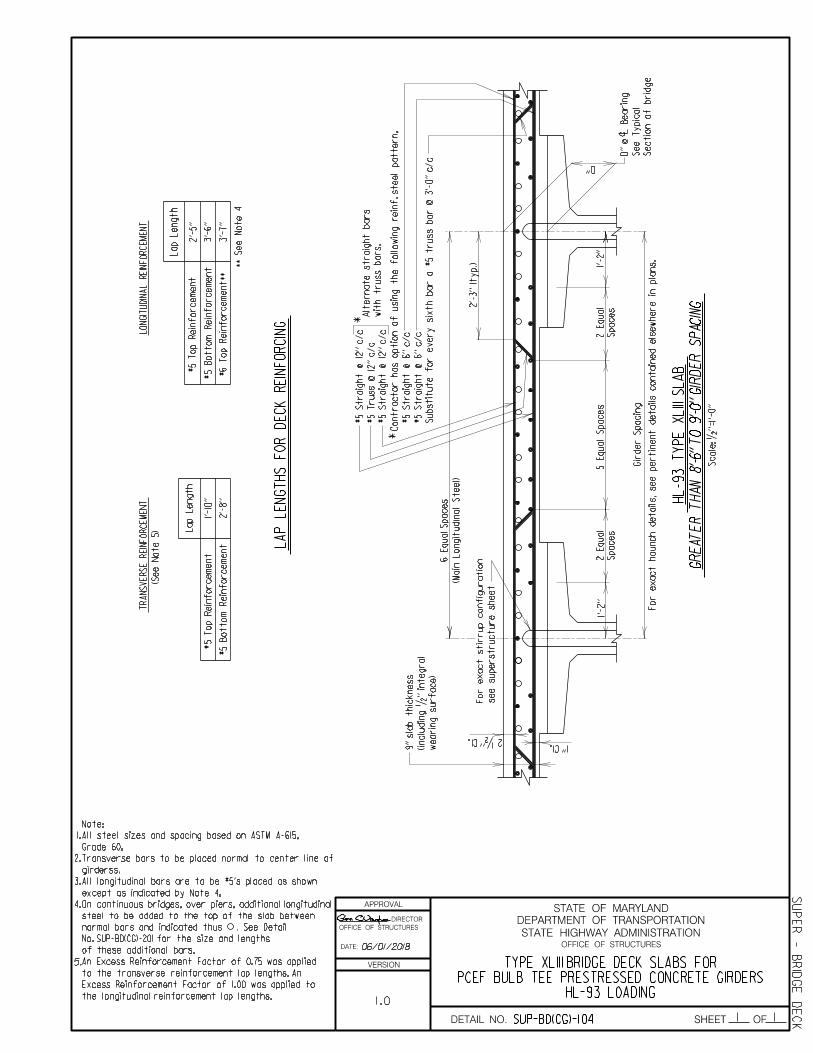
APPROVAL
DIRECTOR
OFFICE OF STRUCTURES
DATE:
VERSION
STATE HIGHWAY ADMINISTRATION
DEPARTMENT OF TRANSPORTATION
STATE OF MARYLAND
OFFICE OF STRUCTURES
DETAIL NO. SHEET
1.
2.
3.
Grade 60.
All steel sizes and spacing based on ASTM A-615,
Note:
except as indicated by Note 4.
All longitudinal bars are to be #5's placed as shown
girderss.
Transverse bars to be placed normal to center line of
4. On continuous bridges, over piers, additional longitudinal
steel to be added to the top of the slab between
of these additional bars.
normal bars and indicated thus . See Detail
No. SUP-BD(CG)-201 for the size and lengths
An Excess Reinforcement Factor of 0.75 was applied
to the transverse reinforcement lap lengths. An
Excess Reinforcement Factor of 1.00 was applied to
the longitudinal reinforcement lap lengths.
5.
(Main
Lo
ngit
udin
al Steel)
c
*
*
Alt
ernate straig
ht bars
wit
h truss bars.
For e
xact haunch details, see
pertin
ent details co
ntain
ed els
ew
here in pla
ns.
Co
ntractor has o
ptio
n of
usin
g the f
oll
owin
g reinf. steel p
attern,
See
Ty
pic
al
2 •'' Cl.1'' Cl.
D''
D'' @
Bearin
g
Scale: •''
=1'-0''
5
Equal S
paces
For e
xact stirrup co
nfig
uratio
n
Gir
der
Spacin
g
1'-2''
1'-2''
GR
EA
TE
R
TH
AN 8'-6'' T
O 9'-0'' GIR
DE
R
SP
ACIN
G
HL-93
TY
PE
XLIII S
LA
B
see superstructure sheet
Sectio
n of
brid
ge
#5 Straig
ht
@ 12'' c/c
#5
Truss
@ 12'' c/c
#5 Straig
ht
@ 12'' c/c
#5 Straig
ht
@ 6'' c/c
#5 Straig
ht
@ 6'' c/c
Substit
ute f
or e
very sixth bar a #5 truss bar
@ 3'-
0'' c/c
Spaces
2
Equal
Spaces
2
Equal
6
Equal
Spaces
wearin
g surface)
(inclu
din
g •'' inte
gral
9'' sla
b thic
kness
TR
AN
SV
ER
SE
REIN
FO
RC
EM
EN
TL
ON
GIT
UDIN
AL
REIN
FO
RC
EM
EN
T
#5
To
p
Reinf
orce
me
nt
** See
Note
4
(See
Note
5)
Lap
Le
ngth
#5
Botto
m
Reinf
orce
me
nt
#6
To
p
Reinf
orce
me
nt**
#5
To
p
Reinf
orce
me
nt
Lap
Le
ngth
#5
Botto
m
Reinf
orce
me
nt L
AP
LE
NG
THS
FO
R
DE
CK
REIN
FO
RCIN
G
1'-10''
2'-
8''
2'-
5''
3'-
6''
3'-
7''
2'-
3'' (ty
p.)
06/01/2018
1.0
SUP-BD(CG)-104
HL-93 LOADINGPCEF BULB TEE PRESTRESSED CONCRETE GIRDERS
TYPE XLIII BRIDGE DECK SLABS FOR
SUP
ER - B
RID
GE
DE
CK1 OF 1

APPROVAL
DIRECTOR
OFFICE OF STRUCTURES
DATE:
VERSION
STATE HIGHWAY ADMINISTRATION
DEPARTMENT OF TRANSPORTATION
STATE OF MARYLAND
OFFICE OF STRUCTURES
DETAIL NO. SHEET OF
Grade 60.
All steel sizes and spacing based on ASTM A-615,
Note:
girderss.
Transverse bars to be placed normal to center line of
3.
4. On continuous bridges, over piers, additional longitudinal
steel to be added to the top of the slab between
of these additional bars.
normal bars and indicated thus . See Detail
No. SUP-BD(CG)-201 for the size and lengths
except as indicated by Note 4.
All longitudinal bars are to be #5's placed as shown
An Excess Reinforcement Factor of 0.75 was applied
to the transverse reinforcement lap lengths. An
Excess Reinforcement Factor of 1.00 was applied to
the longitudinal reinforcement lap lengths.
5.
2.
1.
Scale: •''
=1'-0''
HL-93
TY
PE
XLIV
SL
AB
GR
EA
TE
R
TH
AN 9'-0'' T
O 9'-6'' GIR
DE
R
SP
ACIN
G
(Main
Lo
ngit
udin
al Steel)
c
*
*
Alt
ernate straig
ht bars
wit
h truss bars.
For e
xact haunch details, see
pertin
ent details co
ntain
ed els
ew
here in pla
ns.
Co
ntractor has o
ptio
n of
usin
g the f
oll
owin
g reinf. steel p
attern,
See
Ty
pic
al
2 •'' Cl.
1'' Cl.
D''
D'' @
Bearin
g
For e
xact stirrup co
nfig
uratio
n
Gir
der
Spacin
g
1'-2''
1'-2''
6
Equal S
paces
Sectio
n of
brid
ge
see superstructure sheet
#5 Straig
ht
@ 5•'' c/c
#5
Truss
@ 11'' c/c
Substit
ute f
or e
very sixth bar a #5 truss bar
@ 2'-
9'' c/c
#5 Straig
ht
@ 5•'' c/c
#5 Straig
ht
@ 11'' c/c
#5 Straig
ht
@ 11'' c/c
7
Equal
Spaces
Spaces
3
Equal
Spaces
3
Equal
wearin
g surface)
(inclu
din
g •'' inte
gral
9'' sla
b thic
kness
TR
AN
SV
ER
SE
REIN
FO
RC
EM
EN
TL
ON
GIT
UDIN
AL
REIN
FO
RC
EM
EN
T
#5
To
p
Reinf
orce
me
nt
** See
Note
4
(See
Note
5)
Lap
Le
ngth
#5
Botto
m
Reinf
orce
me
nt
#6
To
p
Reinf
orce
me
nt**
#5
To
p
Reinf
orce
me
nt
Lap
Le
ngth
#5
Botto
m
Reinf
orce
me
nt L
AP
LE
NG
THS
FO
R
DE
CK
REIN
FO
RCIN
G
1'-10''
2'-
8''
2'-
5''
3'-
6''
3'-
7''
2'-
4'' (ty
p.)
06/01/2018
1.0
SUP-BD(CG)-105
HL-93 LOADINGPCEF BULB TEE PRESTRESSED CONCRETE GIRDERS
TYPE XLIV BRIDGE DECK SLABS FOR
SUP
ER - B
RID
GE
DE
CK1 1

APPROVAL
DIRECTOR
OFFICE OF STRUCTURES
DATE:
VERSION
STATE HIGHWAY ADMINISTRATION
DEPARTMENT OF TRANSPORTATION
STATE OF MARYLAND
OFFICE OF STRUCTURES
DETAIL NO. SHEET OF
Scale: •''
=1'-0''
(Main
Lo
ngit
udin
al Steel)
c
*
*
Alt
ernate straig
ht bars
wit
h truss bars.
For e
xact haunch details, see
pertin
ent details co
ntain
ed els
ew
here in pla
ns.
Co
ntractor has o
ptio
n of
usin
g the f
oll
owin
g reinf. steel p
attern, S
ee
Ty
pic
al
2 •'' Cl.
1'' Cl.
D''
D'' @
Bearin
g
For e
xact stirrup co
nfig
uratio
n
Gir
der
Spacin
g
1'-2''
1'-2''
6
Equal S
paces
HL-93
TY
PE
XL
V
SL
AB
GR
EA
TE
R
TH
AN 9'-6'' T
O 10'-0'' GIR
DE
R
SP
ACIN
G
Sectio
n of
brid
ge
see superstructure sheet
#5 Straig
ht
@ 12'' c/c
#5
Truss
@ 12'' c/c
#5 Straig
ht
@ 12'' c/c
#5 Straig
ht
@ 6'' c/c
#5 Straig
ht
@ 6'' c/c
Substit
ute f
or e
very sixth bar a #5 truss bar
@ 3'-
0'' c/c
7
Equal
Spaces
Spaces
3
Equal
Spaces
3
Equal
wearin
g surface)
(inclu
din
g •'' inte
gral
9'' sla
b thic
kness
Grade 60.
All steel sizes and spacing based on ASTM A-615,
Note:
except as indicated by Note 4.
All longitudinal bars are to be #5's placed as shown
girderss.
Transverse bars to be placed normal to center line of
TR
AN
SV
ER
SE
REIN
FO
RC
EM
EN
TL
ON
GIT
UDIN
AL
REIN
FO
RC
EM
EN
T
#5
To
p
Reinf
orce
me
nt
** See
Note
4
(See
Note
5)
Lap
Le
ngth
#5
Botto
m
Reinf
orce
me
nt
#6
To
p
Reinf
orce
me
nt**
#5
To
p
Reinf
orce
me
nt
Lap
Le
ngth
#5
Botto
m
Reinf
orce
me
nt L
AP
LE
NG
THS
FO
R
DE
CK
REIN
FO
RCIN
G
1'-10''
2'-
8''
2'-
5''
3'-
6''
3'-
7''
2'-
6'' (ty
p.)
4. On continuous bridges, over piers, additional longitudinal
steel to be added to the top of the slab between
of these additional bars.
normal bars and indicated thus . See Detail
No. SUP-BD(CG)-201 for the size and lengths
An Excess Reinforcement Factor of 0.75 was applied
to the transverse reinforcement lap lengths. An
Excess Reinforcement Factor of 1.00 was applied to
the longitudinal reinforcement lap lengths.
5.
1.
2.
3.
06/01/2018
1.0
SUP-BD(CG)-106
HL-93 LOADINGPCEF BULB TEE PRESTRESSED CONCRETE GIRDERS
TYPE XLV BRIDGE DECK SLABS FOR
1 1
SUP
ER - B
RID
GE
DE
CK

APPROVAL
DIRECTOR
OFFICE OF STRUCTURES
DATE:
VERSION
STATE HIGHWAY ADMINISTRATION
DEPARTMENT OF TRANSPORTATION
STATE OF MARYLAND
OFFICE OF STRUCTURES
DETAIL NO. SHEET OF
Grade 60.
All steel sizes and spacing based on ASTM A-615,
Note:
except as indicated by Note 4.
All longitudinal bars are to be #5's placed as shown
girderss.
Transverse bars to be placed normal to center line of
4. On continuous bridges, over piers, additional longitudinal
steel to be added to the top of the slab between
of these additional bars.
normal bars and indicated thus . See Detail
No. SUP-BD(CG)-201 for the size and lengths
An Excess Reinforcement Factor of 0.75 was applied
to the transverse reinforcement lap lengths. An
Excess Reinforcement Factor of 1.00 was applied to
the longitudinal reinforcement lap lengths.
5.
3.
2.
1.
Scale: •''
=1'-0''
(Main
Lo
ngit
udin
al Steel)
c
*
*
Alt
ernate straig
ht bars
wit
h truss bars.
For e
xact haunch details, see
pertin
ent details co
ntain
ed els
ew
here in pla
ns.
Co
ntractor has o
ptio
n of
usin
g the f
oll
owin
g reinf. steel p
attern,
See
Ty
pic
al
2 •'' Cl.
1'' Cl.
D''
D'' @
Bearin
g
For e
xact stirrup co
nfig
uratio
n
Gir
der
Spacin
g
1'-2''
1'-2''
7
Equal S
paces
GR
EA
TE
R
TH
AN 10'-0'' T
O 10'-6'' GIR
DE
R
SP
ACIN
G
HL-93
TY
PE
XL
VI S
LA
B
see superstructure sheet
Sectio
n of
brid
ge
#5
Truss
@ 11'' c/c
#5 Straig
ht
@ 5•'' c/c
Substit
ute f
or e
very sixth bar a #5 truss bar
@ 2'-
9'' c/c
#5 Straig
ht
@ 11'' c/c
#5 Straig
ht
@ 11'' c/c
#5 Straig
ht
@ 5•'' c/c
7
Equal
Spaces
Spaces
3
Equal
Spaces
3
Equal
wearin
g surface)
(inclu
din
g •'' inte
gral
9'' sla
b thic
kness
TR
AN
SV
ER
SE
REIN
FO
RC
EM
EN
TL
ON
GIT
UDIN
AL
REIN
FO
RC
EM
EN
T
#5
To
p
Reinf
orce
me
nt
** See
Note
4
(See
Note
5)
Lap
Le
ngth
#5
Botto
m
Reinf
orce
me
nt
#6
To
p
Reinf
orce
me
nt**
#5
To
p
Reinf
orce
me
nt
Lap
Le
ngth
#5
Botto
m
Reinf
orce
me
nt L
AP
LE
NG
THS
FO
R
DE
CK
REIN
FO
RCIN
G
1'-10''
2'-
8''
2'-
5''
3'-
6''
3'-
7''
2'-
8'' (ty
p.)
06/01/2018
1.0
SUP-BD(CG)-107
HL-93 LOADINGPCEF BULB TEE PRESTRESSED CONCRETE GIRDERS
TYPE XLVI BRIDGE DECK SLABS FOR
SUP
ER - B
RID
GE
DE
CK11
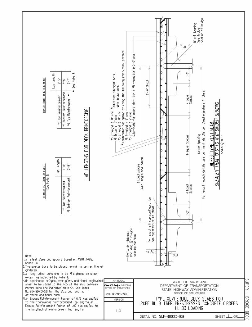
APPROVAL
DIRECTOR
OFFICE OF STRUCTURES
DATE:
VERSION
STATE HIGHWAY ADMINISTRATION
DEPARTMENT OF TRANSPORTATION
STATE OF MARYLAND
OFFICE OF STRUCTURES
DETAIL NO. SHEET OF
except as indicated by Note 4.
All longitudinal bars are to be #5's placed as shown
girderss.
Transverse bars to be placed normal to center line of
4. On continuous bridges, over piers, additional longitudinal
steel to be added to the top of the slab between
of these additional bars.
normal bars and indicated thus . See Detail
No. SUP-BD(CG)-201 for the size and lengths
An Excess Reinforcement Factor of 0.75 was applied
to the transverse reinforcement lap lengths. An
Excess Reinforcement Factor of 1.00 was applied to
the longitudinal reinforcement lap lengths.
5.
3.
2.
1.
Scale: •''
=1'-0''
(Main
Lo
ngit
udin
al Steel)
c
*
*
Alt
ernate straig
ht bars
wit
h truss bars.
For e
xact haunch details, see
pertin
ent details co
ntain
ed els
ew
here in pla
ns.
Co
ntractor has o
ptio
n of
usin
g the f
oll
owin
g reinf. steel p
attern,
See
Ty
pic
al
2 •'' Cl.
1'' Cl.
D''
D'' @
Bearin
g
For e
xact stirrup co
nfig
uratio
n
Gir
der
Spacin
g
1'-2''
1'-2''
8
Equal S
paces
GR
EA
TE
R
TH
AN 10'-6'' T
O 11'-0'' GIR
DE
R
SP
ACIN
G
HL-93
TY
PE
XL
VII S
LA
B
see superstructure sheet
Sectio
n of
brid
ge
#5 Straig
ht
@ 10'' c/c
#5
Truss
@ 10'' c/c
#5 Straig
ht
@ 10'' c/c
#5 Straig
ht
@ 5'' c/c
#5 Straig
ht
@ 5'' c/c
Substit
ute f
or e
very sixth bar a #5 truss bar
@ 2'-
6'' c/c
Spaces
4
Equal
Spaces
4
Equal
8
Equal
Spaces
wearin
g surface)
(inclu
din
g •'' inte
gral
9•'' sla
b thic
kness
TR
AN
SV
ER
SE
REIN
FO
RC
EM
EN
TL
ON
GIT
UDIN
AL
REIN
FO
RC
EM
EN
T
#5
To
p
Reinf
orce
me
nt
** See
Note
4
(See
Note
5)
Lap
Le
ngth
#5
Botto
m
Reinf
orce
me
nt
#6
To
p
Reinf
orce
me
nt**
#5
To
p
Reinf
orce
me
nt
Lap
Le
ngth
#5
Botto
m
Reinf
orce
me
nt L
AP
LE
NG
THS
FO
R
DE
CK
REIN
FO
RCIN
G
1'-10''
2'-
8''
2'-
5''
3'-
6''
3'-
7''
2'-
10'' (ty
p.)
Grade 60.
All steel sizes and spacing based on ASTM A-615,
Note:
06/01/2018
1.0
SUP-BD(CG)-108
SUP
ER - B
RID
GE
DE
CK1 1
HL-93 LOADINGPCEF BULB TREE PRESTRESSED CONCRETE GIRDERS
TYPE XLVII BRIDGE DECK SLABS FOR

APPROVAL
DIRECTOR
OFFICE OF STRUCTURES
DATE:
VERSION
STATE HIGHWAY ADMINISTRATION
DEPARTMENT OF TRANSPORTATION
STATE OF MARYLAND
OFFICE OF STRUCTURES
DETAIL NO. SHEET OF
Scale: •''
=1'-0''
GR
EA
TE
R
TH
AN 11'-0'' T
O 11'-6'' GIR
DE
R
SP
ACIN
G
HL-93
TY
PE
XL
VIII S
LA
B
(Main
Lo
ngit
udin
al Steel)
c
*
*
Alt
ernate straig
ht bars
wit
h truss bars.
For e
xact haunch details, see
pertin
ent details co
ntain
ed els
ew
here in pla
ns.
Co
ntractor has o
ptio
n of
usin
g the f
oll
owin
g reinf. steel p
attern,
See
Ty
pic
al
2 •'' Cl.
1'' Cl.
D''
D'' @
Bearin
g
For e
xact stirrup co
nfig
uratio
n
Gir
der
Spacin
g
1'-2''
1'-2''
8
Equal S
paces
Sectio
n of
brid
ge
see superstructure sheet
#5 Straig
ht
@ 10'' c/c
#5
Truss
@ 10'' c/c
#5 Straig
ht
@ 10'' c/c
#5 Straig
ht
@ 5'' c/c
#5 Straig
ht
@ 5'' c/c
Substit
ute f
or e
very sixth bar a #5 truss bar
@ 2'-
6'' c/c
Spaces
4
Equal
Spaces
4
Equal
8
Equal
Spaces
wearin
g surface)
(inclu
din
g •'' inte
gral
10'' sla
b thic
kness
TR
AN
SV
ER
SE
REIN
FO
RC
EM
EN
TL
ON
GIT
UDIN
AL
REIN
FO
RC
EM
EN
T
#5
To
p
Reinf
orce
me
nt
** See
Note
4
(See
Note
5)
Lap
Le
ngth
#5
Botto
m
Reinf
orce
me
nt
#6
To
p
Reinf
orce
me
nt**
#5
To
p
Reinf
orce
me
nt
Lap
Le
ngth
#5
Botto
m
Reinf
orce
me
nt L
AP
LE
NG
THS
FO
R
DE
CK
REIN
FO
RCIN
G
1'-10''
2'-
8''
2'-
5''
3'-
6''
3'-
7''
1.
2.
3.
Grade 60.
All steel sizes and spacing based on ASTM A-615,
Note:
except as indicated by Note 4.
All longitudinal bars are to be #5's placed as shown
girderss.
Transverse bars to be placed normal to center line of
2'-
11'' (ty
p.)
4. On continuous bridges, over piers, additional longitudinal
steel to be added to the top of the slab between
of these additional bars.
normal bars and indicated thus . See Detail
No. SUP-BD(CG)-201 for the size and lengths
An Excess Reinforcement Factor of 0.75 was applied
to the transverse reinforcement lap lengths. An
Excess Reinforcement Factor of 1.00 was applied to
the longitudinal reinforcement lap lengths.
5.
06/01/2018
1.0HL-93 LOADING
PCEF BULB TEE PRESTRESSED CONCRETE GIRDERSTYPE XLVIII BRIDGE DECK SLABS FOR
SUP-BD(CG)-109
SUP
ER - B
RID
GE
DE
CK1 1
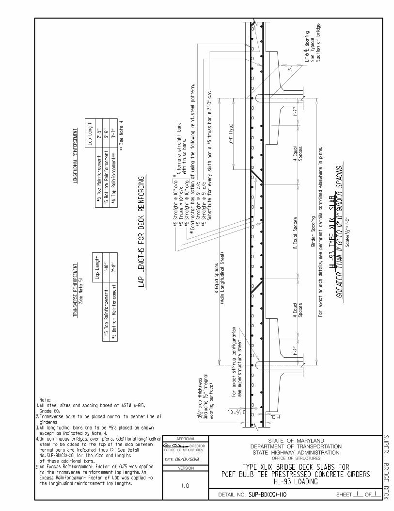
APPROVAL
DIRECTOR
OFFICE OF STRUCTURES
DATE:
VERSION
STATE HIGHWAY ADMINISTRATION
DEPARTMENT OF TRANSPORTATION
STATE OF MARYLAND
OFFICE OF STRUCTURES
DETAIL NO. SHEET OF
Scale: •''
=1'-0''
GR
EA
TE
R
TH
AN 11'-6'' T
O 12'-0'' GIR
DE
R
SP
ACIN
G
(Main
Lo
ngit
udin
al Steel)
c
*
*
Alt
ernate straig
ht bars
wit
h truss bars.
For e
xact haunch details, see
pertin
ent details co
ntain
ed els
ew
here in pla
ns.
Co
ntractor has o
ptio
n of
usin
g the f
oll
owin
g reinf. steel p
attern,
See
Ty
pic
al
2 •'' Cl.
1'' Cl.
D''
D'' @
Bearin
g
For e
xact stirrup co
nfig
uratio
n
Gir
der
Spacin
g
1'-2''
1'-2''
8
Equal S
paces
HL-93
TY
PE
XLIX
SL
AB
Sectio
n of
brid
ge
see superstructure sheet
#5 Straig
ht
@ 10'' c/c
#5
Truss
@ 10'' c/c
#5 Straig
ht
@ 10'' c/c
#5 Straig
ht
@ 5'' c/c
#5 Straig
ht
@ 5'' c/c
Substit
ute f
or e
very sixth bar a #5 truss bar
@ 3'-
0'' c/c
Spaces
4
Equal
Spaces
4
Equal
8
Equal
Spaces
wearin
g surface)
(inclu
din
g •'' inte
gral
10•'' sla
b thic
kness
TR
AN
SV
ER
SE
REIN
FO
RC
EM
EN
TL
ON
GIT
UDIN
AL
REIN
FO
RC
EM
EN
T
#5
To
p
Reinf
orce
me
nt
** See
Note
4
(See
Note
5)
Lap
Le
ngth
#5
Botto
m
Reinf
orce
me
nt
#6
To
p
Reinf
orce
me
nt**
#5
To
p
Reinf
orce
me
nt
Lap
Le
ngth
#5
Botto
m
Reinf
orce
me
nt L
AP
LE
NG
THS
FO
R
DE
CK
REIN
FO
RCIN
G
1'-10''
2'-
8''
2'-
5''
3'-
6''
3'-
7''
1.
2.
3.
Grade 60.
All steel sizes and spacing based on ASTM A-615,
Note:
except as indicated by Note 4.
All longitudinal bars are to be #5's placed as shown
girderss.
Transverse bars to be placed normal to center line of
3'-
1'' (t
yp.)
4. On continuous bridges, over piers, additional longitudinal
steel to be added to the top of the slab between
of these additional bars.
normal bars and indicated thus . See Detail
No. SUP-BD(CG)-201 for the size and lengths
An Excess Reinforcement Factor of 0.75 was applied
to the transverse reinforcement lap lengths. An
Excess Reinforcement Factor of 1.00 was applied to
the longitudinal reinforcement lap lengths.
5.
06/01/2018
1.0
SUP-BD(CG)-110
HL-93 LOADINGPCEF BULB TEE PRESTRESSED CONCRETE GIRDERS
TYPE XLIX BRIDGE DECK SLABS FOR
SUP
ER - B
RID
GE
DE
CK1 1

APPROVAL
DIRECTOR
OFFICE OF STRUCTURES
DATE:
VERSION
STATE HIGHWAY ADMINISTRATION
DEPARTMENT OF TRANSPORTATION
STATE OF MARYLAND
OFFICE OF STRUCTURES
DETAIL NO. SHEET OF
PLAN
L'
c
c
c Pier
Note:
Additional rebars over pier. For
number and spacing of additional
Location
*c c
c
SPLICE LOCATION LAYOUT
If additional longitudinal reinforcing in
pour requires splicing, then the
reinforcing shall be spliced as
per Splice Location Layout.
15'-0'' Min. 15'-0'' Min.
Stationing Span)
L' (BackStationing Span)
L (Ahead
Bridge Description:
Bar Size *
#
Pier
Pier
Pier
Pier
Pier
Pier
additional
Additional rebars
End of
additional
All bars to be #5 unless
otherwise noted in this
column.
L
Girder
bars, between girders, refer to
D D
T
end of additional
Stagger every other
reinforcing in
top mat
longitudinal reinforcing steel
#5 longitudinal
construction joint
Deck slab
Limits of deck
pour over pier
girder
of exterior
End of
rebar
over piers rebar
splice splice
pier
end of additional steel
Stagger every other
Number and spacing of
additional bars beyond
exterior girder shall
match pattern of
those between stringers
Length of Bar)
D (Development
Bar (T=L'+L+D)
T=Total Length of
Scale: None
Outside face
of superstructure
10'-0'' 10'-0''
20'-0''
construction joint
Deck slab
SLABS OVER PIERS FOR CONCRETE GIRDERSREINFORCING IN CONTINUOUS DECK
ADDITIONAL LONGITUDINAL
SUP
ER - B
RID
GE
DE
CKSUP-BD(CG)-201 1 1
bridge deck slab details.
1.0
12/18/2019

APPROVAL
DIRECTOR
OFFICE OF STRUCTURES
DATE:
VERSION
STATE HIGHWAY ADMINISTRATION
DEPARTMENT OF TRANSPORTATION
STATE OF MARYLAND
OFFICE OF STRUCTURES
DETAIL NO. SHEET OF
SUP
ER
BRID
GE
DE
CK
LENGTHS CONTRIBUTING TO EXPANSION > 70 FEETWITH ELASTOMERIC BEARINGS WITHPRESTRESSED CONCRETE GIRDERS
CONCRETE DIAPHRAGMS AT ABUTMENTS CARRYING
SUP-BD(CG)-301 1 4
1.01
A
A
3ƒ'' cl.
2'' cl.
c
c
2'-0''
2'' cl.cL
Gir
der
L
Gir
der
not shown for clarity.
Normal deck reinforcing
Note:
L of
bearin
g
perpe
ndic
ular to
#5
@ 9'' - pla
ce
''Ty
pic
al
Cross
Sectio
n'' of
brid
ge
overhang and parapet see
For e
xact co
nfig
uratio
n of
bea
ms
bars bet
wee
n
3-#5 straig
ht
L
at abut
me
nt
Brid
ge seat
Scale:
…'' = 1'-0''
EL
EV
ATIO
N
AT
BRID
GE S
EA
T
AR
EA
OV
ER
BE
AM
S
c bearin
g
perpe
ndic
ular to
#5
@ 9'' m
ax. - pla
ce
clear
1'' min.
brid
ge road
way
To
p of
(ty
p.)
aro
und fla
nge
bars pla
ce
d
2-#5
For Section B-B see Sheet 4 of 4.
For Section A-A see Sheet 3 of 4.
Notes:
1.
2.
chee
kwall
To
p of
3.
barrier type.
purposes only. See plans for
F-Shape barrier is for illustrative 07/25/2019

APPROVAL
DIRECTOR
OFFICE OF STRUCTURES
DATE:
VERSION
STATE HIGHWAY ADMINISTRATION
DEPARTMENT OF TRANSPORTATION
STATE OF MARYLAND
OFFICE OF STRUCTURES
DETAIL NO. SHEET OF
SUP
ER
BRID
GE
DE
CK
2 4
LENGTHS CONTRIBUTING TO EXPANSION > 70 FEETWITH ELASTOMERIC EXPANSION BEARINGS
PRESTRESSED CONCRETE GIRDERSCONCRETE DIAPHRAGMS AT ABUTMENTS CARRYING
SUP-BD(CG)-301
1.01
Span
= S
Measure
d alo
ng
L bearin
g
A
For
Sectio
n
A-
A see
3ƒ'' cl.
c
cc
2'-0''
2'' cl.
L gir
der
L gir
der
A
For e
xact co
nfig
uratio
n of
overhang and parapet see
''Ty
pic
al
Cross
Sectio
n'' of
brid
ge
or sid
ewalk is use
d
F-Shape
Barrier, tube railin
g,
of sla
b re
gardle
ss of
whether
Re
bars ''
A'' t
o e
xte
nd to e
nd
Re
bars ''
A''
L
Scale:
…'' = 1'-0''
EL
EV
ATIO
N
AT
BRID
GE S
EA
T
AR
EA
S
OV
ER
BA
CK
WA
LL
c bearin
g
perpe
ndic
ular to
#5
@ 9'' m
ax. - pla
ce
B
B
Sheet 4 of
4.
For
Sectio
n
B-
B see
Sheet 3 of
4.
back
wall
To
p of
brid
ge road
way
To
p of
''A''
Re
bars
(ty
p.)
aro
und fla
nge
bars pla
ce
d
2-#5
For Section B-B see Sheet 4 of 4.
For Section A-A see Sheet 3 of 4.
Notes:
1'' spo
nge ty
pe joint
material f
aste
n to
abut
me
nt
wit
h
co
pper nails
not shown for clarity.Normal deck reinforcingNote:
*
min.) ela
sto
meric pad
of
back
wall (1'-
0''
1'' thic
k
x f
ull d
epth
to abut
me
nt
wit
h co
pper nails.
7‚'' x •'' d
ee
p ke
y. Attach
Sectio
n 911.10, seate
d in
for f
ull le
ngth, co
nf
or
min
g to
ela
sto
mer 1•'' t
hic
k
x 7'' wid
e
Clo
se
d cell
ne
opre
ne spo
nge
accordance
wit
h the
Sectio
n 432.0
3.0
4.
to abut
me
nt back
wall in
Ela
sto
meric pad shall
be attache
d
Note:
1.
2.
3.
barrier type.
purposes only. See plans for
F-Shape barrier is for illustrative 07/25/2019
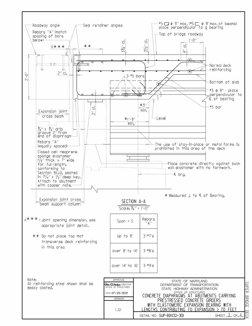
APPROVAL
DIRECTOR
OFFICE OF STRUCTURES
DATE:
VERSION
STATE HIGHWAY ADMINISTRATION
DEPARTMENT OF TRANSPORTATION
STATE OF MARYLAND
OFFICE OF STRUCTURES
DETAIL NO. SHEET OF
07/25/2019
1.01 LENGTHS CONTRIBUTING TO EXPANSION > 70 FEETWITH ELASTOMERIC EXPANSION BEARING WITH
PRESTRESSED CONCRETE GIRDERSCONCRETE DIAPHRAGMS AT ABUTMENTS CARRYING
SUP
ER
BRID
GE
DE
CKSUP-BD(CG)-301 3 4
Span = S
Up to 8' 3-#7's
over 8' to 14' 3-#8's
3-#9'sover 14' to 16'
SECTION A-A
1'-0''
4'' cl.
2•'' cl.
1
Level
c*
c
c brg.
2'' cl.
Scale: ƒ'' = 1'-0''
2'-
0''
Roadway angle
X***
Rebars ''A''
(equally spaced)
1 *
min.
3''
1'-9''
min.*
#5 bar
L of bearing
perpendicular to
#5 @ 9'' - place
Bottom of slab
reinforcing
Normal deck
2'' cl.
''A''
Rebars
3-#5 bars
L
below)
spacing of bars
Rebars ''A'' (match
3ƒ'' cl.
Seal retainer angles
Measured to of Bearing.
with copper nails.
Attach to abutment
in 7‚'' x •'' deep key.
Section 911.10, seated
conforming to
for full length,
1•'' thick x 7'' wide
sponge elastomer
Closed cell neoprene
Top of bridge roadway
Expansion joint
cross beam
X =***
Expansion joint cross
beam support column
prohibited in this area of the deck
The use of stay-in-place or metal forms is
wall elastomer with no formwork.
Place concrete directly against back
**
**
place perpendicular to c bearing#5 @ 9'' max. (#5 @ 9" max. at beams)
appropriate joint detail.
Joint opening dimension, see
in this area
transverse deck reinforcing
Do not place top mat
end of diaphragmgroove 2'' from ƒ'' x ƒ'' drip
epoxy coated.
All reinforcing steel shown shall be
Note:

APPROVAL
DIRECTOR
OFFICE OF STRUCTURES
DATE:
VERSION
STATE HIGHWAY ADMINISTRATION
DEPARTMENT OF TRANSPORTATION
STATE OF MARYLAND
OFFICE OF STRUCTURES
DETAIL NO. SHEET OF
SUP
ER
BRID
GE
DE
CK
LENGTHS CONTRIBUTING TO EXPANSION > 70 FEETWITH ELASTOMERIC EXPANSION BEARING WITH
PRESTRESSED CONCRETE GIRDERSCONCRETE DIAPHRAGMS AT ABUTMENTS CARRYING
SUP-BD(CG)-301
1.01
4 4
07/25/2019
Span = S
Up to 8' 3-#7's
over 8' to 14' 3-#8's
3-#9'sover 14' to 16'
SECTION B-B
2•'' cl.
c brg.
Scale: ƒ'' = 1'-0''
Varie
s
X =
X***
''A''
Rebars
elastomeric pad
1'' thick
*
***
Normal deck
reinforcing
Bottom of slab
and cheekwall
1'' clear between deck
spaced as shown
Rebars ''A''
Roadway angle Seal retainer angles
cl.
2'' min.
Top of bridge roadway
Expansion joint
cross beam
2'' ƒ'' (typ.)
ƒ''
Scale: 3'' = 1'-0''
DRIP GROOVE DETAIL
detail this sheet
of diaphragm, see
groove 2'' from end
ƒ'' xƒ'' drip
with the Section 432.03.04.
to abutment backwall in accordance
Elastomeric pad shall be attached
Note:
Expansion joint cross
beam support column
appropriate joint detail.
Joint opening dimension, see
**in this area
transverse deck reinforcing
Do not place top mat
**
epoxy coated.
All reinforcing steel shown shall be
Note:

APPROVAL
DIRECTOR
OFFICE OF STRUCTURES
DATE:
VERSION
STATE HIGHWAY ADMINISTRATION
DEPARTMENT OF TRANSPORTATION
STATE OF MARYLAND
OFFICE OF STRUCTURES
DETAIL NO. SHEET OF
SUP
ER
BRID
GE
DE
CK
1.02 WITH LENGTHS CONTRIBUTING TO EXPANSION 70 FEETFIXED BEARINGS OR ELASTOMERIC EXPANSION BEARINGS
PRESTRESSED CONCRETE GIRDERS WITH ELASTOMERICCONCRETE DIAPHRAGMS AT ABUTMENTS CARRYING
1 4SUP-BD(CG)-401
A
A
3ƒ'' cl.
2'' cl.
c
c
2'-0''
2'' cl.c
Scale:
…'' = 1'-0''
L
Gir
der
L
Gir
der
not shown for clarity.
Normal deck reinforcing
Note:
L of
bearin
g
perpe
ndic
ular to
#5
@ 9'' - pla
ce
''Ty
pic
al
Cross
Sectio
n'' of
brid
ge
overhang and parapet see
For e
xact co
nfig
uratio
n of
L
bea
ms
bars bet
wee
n
3-#5 straig
ht
c bearin
g
perpe
ndic
ular to
#5
@ 9'' m
ax. - pla
ce
EL
EV
ATIO
N
AT
BRID
GE S
EA
T
AR
EA
OV
ER
BE
AM
S
chee
kwall
To
p of
at abut
me
nt
Brid
ge seat
clear
1'' min.
brid
ge road
way
To
p of
For Section B-B see sheet 4 of 4.
For Section A-A see sheet 3 of 4.
Notes:
2.
1.
3.
barrier type.
purposes only. See plans for
F-Shape barrier is for illustrative
<
12/18/2019

APPROVAL
DIRECTOR
OFFICE OF STRUCTURES
DATE:
VERSION
STATE HIGHWAY ADMINISTRATION
DEPARTMENT OF TRANSPORTATION
STATE OF MARYLAND
OFFICE OF STRUCTURES
DETAIL NO. SHEET OF
SUP
ER
BRID
GE
DE
CK
*
For Section B-B see sheet 4 of 4.
For Section A-A see sheet 3 of 4.
Notes:
2.
1.
Span
= S
Measure
d alo
ng
L bearin
g
A
3ƒ'' cl.
c
c
c
2'-0''
2'' cl.
Scale:
…'' = 1'-0''
1'' spo
nge ty
pe joint
material f
aste
n to
abut
me
nt
wit
h
co
pper nails
L gir
der
L gir
der
A
not shown for clarity.Normal deck reinforcingNote:
For e
xact co
nfig
uratio
n of
overhang and parapet see
''Ty
pic
al
Cross
Sectio
n'' of
brid
ge
or sid
ewalk is use
d
F-Shape
Barrier, tube railin
g,
of sla
b re
gardle
ss of
whether
Re
bars ''
A'' t
o e
xte
nd to e
nd
Re
bars ''
A''
L
7‚'' x •'' d
ee
p ke
y
Sectio
n 911.10, seate
d in
for f
ull le
ngth, co
nf
or
min
g to
ela
storer 1•'' t
hic
k
x 7'' wid
e
Clo
se
d cell
ne
opre
ne spo
nge
c bearin
g
perpe
ndic
ular to
#5
@ 9'' m
ax. - pla
ce
EL
EV
ATIO
N
AT
BRID
GE S
EA
T
AR
EA
S
OV
ER
BA
CK
WA
LL
min.) ela
sto
meric pad
of
back
wall (1'-
0''
1'' thic
k
x f
ull d
epth
*''
A''
Re
bars
brid
ge road
way
To
p of
back
wall
To
p of
accordance
wit
h the
Sectio
n 432.0
3.0
4.
to abut
me
nt dia
phrag
m seat in
Ela
sto
meric pad shall
be attache
d
Note: B
B
(ty
p.)
aro
und fla
nge
bars pla
ce
d
2-#5
1.02 WITH LENGTHS CONTRIBUTING TO EXPANSION 70 FEETFIXED BEARINGS OR ELASTOMERIC EXPANSION BEARINGS
PRESTRESSED CONCRETE GIRDERS WITH ELASTOMERICCONCRETE DIAPHRAGMS AT ABUTMENTS CARRYING
2 4SUP-BD(CG)-401
3.
barrier type.
purposes only. See plans for
F-Shape barrier is for illustrative
<
12/18/2019

APPROVAL
DIRECTOR
OFFICE OF STRUCTURES
DATE:
VERSION
STATE HIGHWAY ADMINISTRATION
DEPARTMENT OF TRANSPORTATION
STATE OF MARYLAND
OFFICE OF STRUCTURES
DETAIL NO. SHEET OF
SUP
ER
BRID
GE
DE
CK
12/18/2019
WITH LENGTHS CONTRIBUTING TO EXPANSION < 70 FEETFIXED BEARINGS OR ELASTOMERIC EXPANSION BEARINGS
PRESTRESSED CONCRETE GIRDERS WITH ELASTOMERICCONCRETE DIAPHRAGMS AT ABUTMENTS CARRYING
SUP-BD(CG)-401 3 4
1.02
SECTION A-A
Span = S
Up to 8' 3-#7's
over 8' to 14' 3-#8's
3-#9'sover 14' to 16'
1'-0''
4'' cl.
2•'' cl.
1
Level
c*
c
2'' cl.
2'' cl.
Scale: ƒ'' = 1'-0''
2'-
0''
(equally spaced)
Rebars ''A''
3 - #5 bars Normal deck
reinforcing
Bottom of slab
#5 @ 9'' - place
perpendicular to
L of bearing
#5 bar
1
min.
3''
1'-9''
min.*
*
''A''
Rebars
Roadway angle
below)
spacing of bars
Rebars ''A'' (match
L
c brg.
in 7‚'' x •'' deep key
Section 911.10, seated
conforming to
for full length,
1•'' thick x 7'' wide
sponge elastorer
Closed cell neoprene
3ƒ'' cl.
perpendicular to c bearing
#5 @ 9'' max. place
Top of bridge roadway
Measured to of Bearing.
6''
prohibited in this area of the deck
The use of stay-in-place or metal forms is
with no formwork.
against back wall elastomer
Place concrete directly
**
**in this area.
transverse deck reinforcing
Do not place top mat
epoxy coated.
All reinforcing steel shown shall be
Note:
detail on sheet 4
of diaphragm, see
groove 2'' from end
ƒ'' xƒ'' drip

APPROVAL
DIRECTOR
OFFICE OF STRUCTURES
DATE:
VERSION
STATE HIGHWAY ADMINISTRATION
DEPARTMENT OF TRANSPORTATION
STATE OF MARYLAND
OFFICE OF STRUCTURES
DETAIL NO. SHEET OF
SUP
ER
BRID
GE
DE
CK
12/18/2019
epoxy coated.
All reinforcing steel shown shall be
Note:
Span = S
Up to 8' 3-#7's
over 8' to 14' 3-#8's
3-#9'sover 14' to 16'
SECTION B-B
2•'' cl.
c brg.
Scale: ƒ'' = 1'-0''
''A''
Rebars
elastomeric pad
1'' thick
*
Normal deck
reinforcing
Bottom of slab
and cheekwall
1'' clear between deck
spaced as shown
Rebars ''A''
Roadway angle
cl.
2'' min.
Top of bridge roadway
2'' ƒ'' (typ.)
ƒ''
Scale: 3'' = 1'-0''
DRIP GROOVE DETAIL
detail this sheet
of diaphragm, see
groove 2'' from end
ƒ'' xƒ'' drip
with the Section 432.03.04.
to abutment backwall in accordance
Elastomeric pad shall be attached
Note:
6''
**
in this area.
transverse deck reinforcing
Do not place top mat
WITH LENGTHS CONTRIBUTING TO EXPANSION < 70 FEETFIXED BEARINGS OR ELASTOMERIC EXPANSION BEARINGS
PERSTRESSED CONCRETE GIRDERS WITH ELASTOMERICCONCRETE DIAPHRAGMS AT ABUTMENTS CARRYING
4 4SUP-BD(CG)-401
1.02

APPROVAL
DIRECTOR
OFFICE OF STRUCTURES
DATE:
VERSION
STATE HIGHWAY ADMINISTRATION
DEPARTMENT OF TRANSPORTATION
STATE OF MARYLAND
OFFICE OF STRUCTURES
DETAIL NO. SHEET OF
RE-BARS ALIGNED WITH TROUGHFOR CONCRETE SLABS ON CONCRETE GIRDERS
STEEL FORMS WHICH REMAIN IN PLACE
SUP
ER - B
RID
GE
DE
CKSUP-BD(CG)-501 1 2
Notes:
Permanent steel deck forms and supports shall
Any permanently exposed form metal where the
galvanized coating has been damaged shall be
thoroughly cleaned, wire brushed and painted
with two coats of zinc-oxide dust primer, Federal
Specification TT-P-641d, Type II, no color added,
to the satisfaction of the Engineer. Minor heat
discoloration in areas of welds need not be
touched up.
Top of Slab
4'-0'' Max. Spacing
Upper (Height > 3'')
Co
ncrete
Deck
Sla
b
De
pth
Height
1''
Continuous High Chair
(Height < 3'')
Slab Bolster Upper
a a
Main Reinforcing Steel Bars.
1''cl.
min.
1'' cl. min.
…''
SECTION
Scale: None
conform to 909.11. Design Span shall be the clear
FORM ANCHOR DETAIL
These forms shall be vertically adjusted to
attain line and grade as required.
distance between girder flanges less two (2) inches.
1'' max. (typ.)
1'' minimum
bearing
Scale: 1'' = 1'-0''
Steel
Reinforcing
Distribution
remain in place.
Steel forms which
4'-0'' Max. Spacing
#3 Bar @
shall not be continuous.
form angle. These anchors
as required along the deck
Provide anchor at each weld
Anchor insert (galvanized):
girder
Prestressed concrete
form manufacturer
as required by
Support system
3.
2.
1.
Supports for rebar shall be provided
by Contractor.
4.
5.
Contractor has option of using this
detail or that shown on 2 of 2, except
on sheet 2 of 2 can be used.
for bridge decks with a flared rebar
pattern. For bridges with a flared
rebar pattern only the detail shown
1.0
12/18/2019
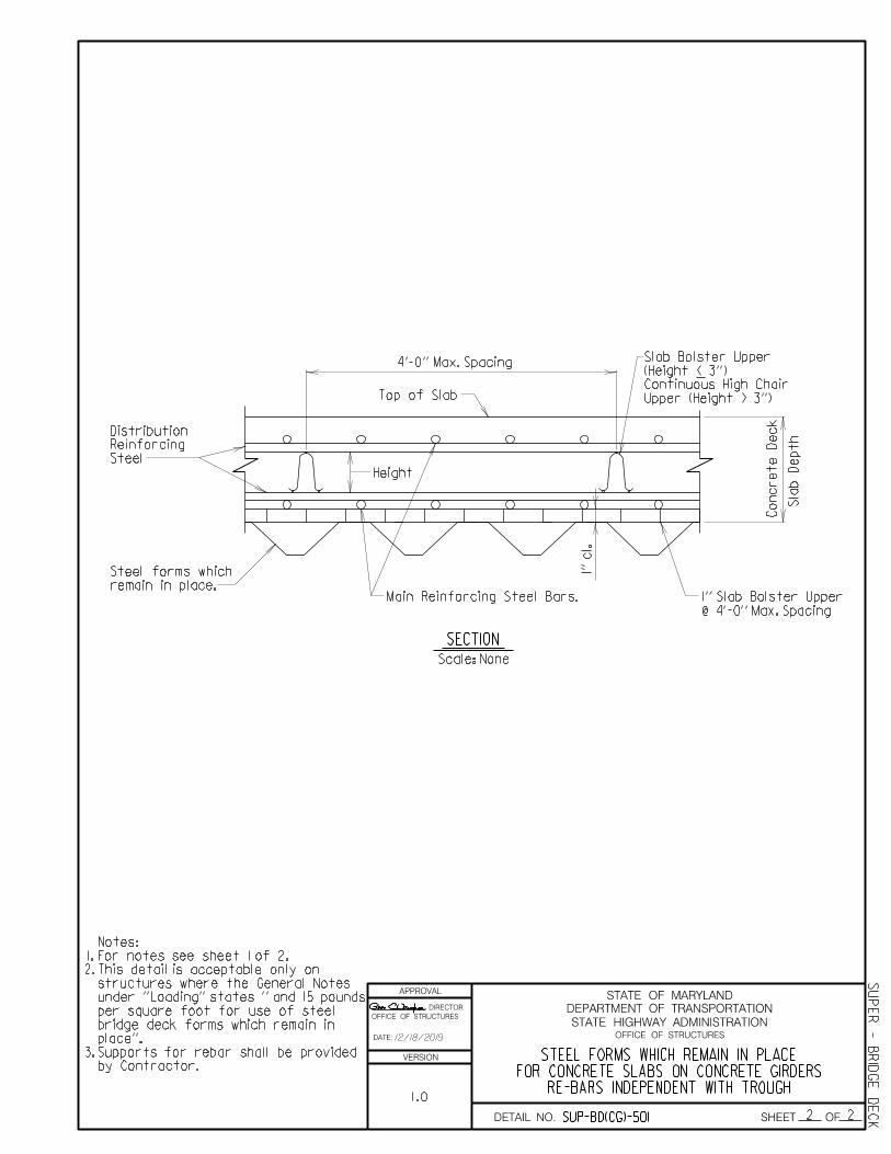
APPROVAL
DIRECTOR
OFFICE OF STRUCTURES
DATE:
VERSION
STATE HIGHWAY ADMINISTRATION
DEPARTMENT OF TRANSPORTATION
STATE OF MARYLAND
OFFICE OF STRUCTURES
DETAIL NO. SHEET OF
RE-BARS INDEPENDENT WITH TROUGHFOR CONCRETE SLABS ON CONCRETE GIRDERS
STEEL FORMS WHICH REMAIN IN PLACE
SUP
ER - B
RID
GE
DE
CKSUP-BD(CG)-501 2 2
Top of Slab
4'-0'' Max. Spacing
Upper (Height > 3'')
Co
ncrete
Deck
Sla
b
De
pth
Height
Continuous High Chair
(Height < 3'')
Slab Bolster Upper
Main Reinforcing Steel Bars.
SECTION
Scale: None
1'' cl.
Steel
Reinforcing
Distribution
remain in place.
Steel forms which
@ 4'-0'' Max. Spacing
1'' Slab Bolster Upper
Notes:
For notes see sheet 1 of 2.
This detail is acceptable only on
structures where the General Notes
3.
under ''Loading'' states '' and 15 pounds
per square foot for use of steel
by Contractor.
Supports for rebar shall be provided
place''.
bridge deck forms which remain in
2.
1.
1.0
12/18/2019

OFFICE OF STRUCTURES STRUCTURAL DETAIL MANUAL
Chapter 03 - Superstructure
Section 01 – Bridge Deck
SUB-SECTION 04
STAGED CONSTRUCTION
(SUP-BD(SC))

APPROVAL
DIRECTOR
OFFICE OF STRUCTURES
DATE:
VERSION
STATE HIGHWAY ADMINISTRATION
DEPARTMENT OF TRANSPORTATION
STATE OF MARYLAND
OFFICE OF STRUCTURES
DETAIL NO. SHEET OF
LAP SPLICE ALTERNATIVESTRUSS BARS DURING STAGE CONSTRUCTION
SPLICING OF BRIDGE DECK SLAB
SUP
ER - B
RID
GE
DE
CKSUP-BD(SC)-101 1 1
2.0
04/30/2018
Top of Slab
Prior Stage Slab Construction
Stringer
slab, to lap with truss bar.
lap with truss bar.
Prior Stage Slab Construction.
Constr. Gap
Normal Truss Bar.
SECTION
TYPE 1 SPLICE
SECTION
TYPE 11 SPLICE
Scale: •'' = 1'-0''
Scale: •'' = 1'-0''
Top of Slab
Prior Stage Slab Construction
Constr. Gap
SECTION
Scale: •'' = 1'-0''
TYPE 111 SPLICE
bottom of slab
Additional bar, top of slab, to
Additional bar, bottom of
Additional bar
Normal truss bar
Constr. Gap
See Note 3
Second Stage Slab Construction.
Stage 1 additional bar.
Additional bar. Splice with
use in gap)
sloped leg (do not
Normal location of truss
1'-10''
2'-8''
1'-10''
2'-8'' 2'-8''
2'-8''
2'-8''
1'-10''
See Note 3
See Note 3
Second Stage Slab Construction
lap with truss
Second Stage Slab Construction
placed over stringers.
Construction joints shall not be
Constr. Gap dim. = 2'-9'' min.
over Pier lap length details.
Longitudinal and Additional Top Bar
See Det. No. SUP-BD(DT)-201 for
construction gap location.
See Contract Drawing for
Notes:
lap with truss
4.
3.
2.
1.

APPROVAL
DIRECTOR
OFFICE OF STRUCTURES
DATE:
VERSION
STATE HIGHWAY ADMINISTRATION
DEPARTMENT OF TRANSPORTATION
STATE OF MARYLAND
OFFICE OF STRUCTURES
DETAIL NO. SHEET OF
GENERAL NOTES
Longitudinal deck reinforcing steel not shown.
Existing slab shown dashed.
Splicer bars and normal transverse reinforcing steel
to be placed in same horizontal plane.
These splice bars will not be measured for payment,
but all costs thereof shall be included in the Contract
Root diameter of threaded portion of splicer bar must be
diameter to next size is permissable to maintain this
FOR OFFICE USE ONLY
This detail is intended for use on stage construction
where the gap between stages of construction does not
accomodate the minimum bar lap lengths.
The steel manufacturer shall furnish certification with
actual test results for each heat of steel, showing that
Certification:
1.
2.
3.
4.
6.
requirement.
In no case shall the splicer rebar coupler flange encroach
into the slab top or bottom concrete cover. Either no
flange or clipping the top and bottom edges of the
5a.
5b.
Top of slab
See details below
A
A
SECTION A-A
Scale: •'' = 1'-0''Flange Clip flange
Clip flange
Flange Clip flange
Clip flange
FRONT VIEW ROUND FLANGE FRONT VIEW SQUARE FLANGE
Scale: None Scale: None
equal to nominal diameter of designed bar. Increasing bar
flange prior to application of the epoxy coating in the
shop is permissable. (See details below)
the material conforms to these Specifications.
lump sum price for the pertinent Epoxy Coated Reinforcing
Steel items.
(NO AREA AVAILABLE FOR LAPPING)STEEL DURING STAGE CONSTRUCTION
SPLICING OF BRIDGE DECK SLAB REINFORCING
SUP
ER - B
RID
GE
DE
CKSUP-BD(SC)-102 1 4
04/30/2018
2.0

2 4
DATE:
STATE HIGHWAY ADMINISTRATION
DEPARTMENT OF TRANSPORTATION
STATE OF MARYLAND
SHEET OF
APPROVAL
OFFICE OF STRUCTURES
DIRECTOR
OFFICE OF STRUCTURES
SUP-BD(SC)-102
SUPER - BRID
GE
DEC
K
COUPLER BAR SPLICE ALTERNATIVESTRUSS BARS DURING STAGE CONSTRUCTION
SPLICING OF BRIDGE DECK SLAB
2.
1.
VERSION
DETAIL NO.
2.0
SE
CTIO
N
Scale: •'' = 1'-0''
OP
TIO
N 11
Prior
Stage
Sla
b
Co
nstructio
nSeco
nd
Stage
Sla
b
Co
nstructio
n
*
*
''A'' Dim.
> 0
measure
d
botto
m
bar syste
m sho
wn abo
ve.
external threads
may re
pla
ce
Full le
ngth additio
nal
bar
wit
h
2'-
1''
2'-
1''
2'-
11''
2'-
8''
2'-
8''
Co
nstructio
n
Gap dim.
< 2'-
9''
To
p le
g dim. as calc
ulate
dCo
nstructio
n gap
SE
CTIO
N
Scale: •'' = 1'-0''
Prior
Stage
Sla
b
Co
nstructio
nSeco
nd
Stage
Sla
b
Co
nstructio
n
*
fro
m
be
nd point (t
yp.)
''A'' Dim.
> 0
measure
d
2'-
1''
2'-
1''
2'-
11''
2'-
8''
2'-
8''
To
p le
g dim. as calc
ulate
dCo
nstructio
n gap
botto
m
bar syste
m sho
wn abo
ve.
wit
h internal threads
may re
pla
ce
Full le
ngth threade
d additio
nal b
ar
2'-
11''
fro
m
be
nd point (t
yp.)
> 0
measure
d
OP
TIO
N 1
sla
b, to la
p
wit
h truss bar
Additio
nal
bar, botto
m
of
sla
b, to la
p
wit
h truss bar
Additio
nal
bar, botto
m
of
**
**
**
*
**
**
Cannot
mo
ve
be
nd point to acco
mo
date la
p splice.
Dim
ensio
n
= la
p le
ngth
+ 3''
***
of truss bar
in botto
m le
g area
not per
mitte
d
Three
bar bundling
**
*
**
**
*
*
04/30/2018
Work with sheets 3 and 4 of 4.
For General Notes see Sht. No. 1 of 4.
Notes:
SUP-BD(DT)-201
Other Related Details
fro
m sla
b detail
fro
m
be
nd point (t
yp.)
fro
m sla
b detail

APPROVAL
DIRECTOR
OFFICE OF STRUCTURES
DATE:
VERSION
STATE HIGHWAY ADMINISTRATION
DEPARTMENT OF TRANSPORTATION
STATE OF MARYLAND
OFFICE OF STRUCTURES
DETAIL NO. SHEET OFFor General Notes see Sht. No. 1 of 4.
Work with sheets 2 and 4 of 4.
Notes:
2.
1.
SE
CTIO
N
Scale: •'' = 1'-0''
OP
TIO
N 1V
Prior
Stage
Sla
b
Co
nstructio
nSeco
nd
Stage
Sla
b
Co
nstructio
n
sla
b, to to
p of truss bar
Additio
nal b
ar, botto
m
of
2'-
1''
2'-
1''
1'-10''
1'-10''
2'-
11''
2'-
11''
gap
Co
nstr.
be
nd point (t
yp.)
measure
d fro
m
"A"
Dim.
> 0
-
SE
CTIO
N
Scale: •'' = 1'-0''
OP
TIO
N 11
1
Prior
Stage
Sla
b
Co
nstructio
nSeco
nd
Stage
Sla
b
Co
nstructio
n
sla
b, to to
p of truss bar
Additio
nal b
ar, botto
m
of
2'-
1''
2'-
1''
2'-
11''
2'-
11''
2'-
8''
2'-
8''
gap
Co
nstr.
be
nd point (t
yp.)
measure
d fro
m
"A"
Dim.
> 0 -
Co
nstructio
n
Gap dim.
< 2'-
9''
Dim
ensio
n
= la
p le
ngth
+ 3''
***
*
**
**
**
** **
**
* **
**
COUPLER BAR SPLICE ALTERNATIVESTRUSS BARS DURING STAGE CONSTRUCTION
SPLICING OF BRIDGE DECK SLAB
SUP
ER - B
RID
GE
DE
CKSUP-BD(SC)-102
2.0
04/30/2018
3 4

APPROVAL
DIRECTOR
OFFICE OF STRUCTURES
DATE:
VERSION
STATE HIGHWAY ADMINISTRATION
DEPARTMENT OF TRANSPORTATION
STATE OF MARYLAND
OFFICE OF STRUCTURES
DETAIL NO. SHEET OF
04/30/2018
2.0COUPLER BAR SPLICE ALTERNATIVES
TRUSS BARS DURING STAGE CONSTRUCTIONSPLICING OF BRIDGE DECK SLAB
SUP
ER - B
RID
GE
DE
CKSUP-BD(SC)-102 4 4
SE
CTIO
N
Scale: •'' = 1'-0''
OP
TIO
N
V1
*
*
Co
nstr.
Gap
Prior
Stage
Sla
b
Co
nstructio
nSeco
nd
Stage
Sla
b
Co
nstructio
n
botto
m
bar syste
m sho
wn abo
ve.
wit
h internal threads
may re
pla
ce
Full le
ngth threade
d additio
nal b
ar
2'-
8''
2'-
8''
2'-
11''
1'-10''
Co
nstr.
Gap dim.
< 2'-
9''
Co
nstr.
Gap dim.
> 1'-11''
SE
CTIO
N
Scale: •'' = 1'-0''
*Co
nstr.
Gap
Prior
Stage
Sla
b
Co
nstructio
nSeco
nd
Stage
Sla
b
Co
nstructio
n
2'-
8''
2'-
8''
2'-
11''1'-10''
2'-
11''
> 0'' m
easure
d fro
m
be
nd point (t
yp.)
of truss bar
in botto
m le
g area
not per
mitte
d
Three
bar bundling
splice
bar
Threade
d co
uple
r
sla
b, to la
p
wit
h truss bar
Additio
nal b
ar, botto
m
of
sla
b, to la
p
wit
h truss bar
Additio
nal b
ar, botto
m
of
OP
TIO
N
V
be
nd point (t
yp.)
measure
d fro
m
"A"
Dim.
> 0
-
be
nd point (t
yp.)
measure
d fro
m
"A"
Dim.
> 0
-
Dim
ensio
n
= la
p le
ngth
+ 3''
**
**
**
**
2.
1.
For General Notes see Sht. No. 1 of 4.
Work with sheets 2 and 3 of 4.
Notes:
SUP-BD(DT)-201
Other Related Details

APPROVAL
DIRECTOR
OFFICE OF STRUCTURES
DATE:
VERSION
STATE HIGHWAY ADMINISTRATION
DEPARTMENT OF TRANSPORTATION
STATE OF MARYLAND
OFFICE OF STRUCTURES
DETAIL NO. SHEET OFX X
1st pour
1st pour 2nd pour
Existing deck
Support angles
Continuous
support
12'' lap
min.
12'' lap
min.
SECTION VIEW FOR 1st POUR
SECTION VIEW FOR 2nd POUR
Scale: •'' = 1'-0''
Scale: •'' = 1'-0''
A
A
3'' max. pans to provide a smooth vertical joint
Bulkhead must block troughs in form
as required
Supports spaced
remain in place
Steel forms which
traffic is allowed on it.
after 1st pour has properly cured and
Continuous support may be removed
shown for clarity.
Reinforcing steel not
Note:
reinforcing from its proper position.
Hanger straps shall not deflect
is located.
longitudinal deck construction joint
wood forms in spans where a
This detail can be used in lieu of
Notes:
in the sloped side of pan)
installed in each trough
Hanger strap (to be
2.
1.
STEEL FORMS WHICH REMAIN IN PLACESPLIT PAN CONSTRUCTION FOR
SUP
ER - B
RID
GE
DE
CK
07/20/2006
1.0
SUP-BD(SC)-103

APPROVAL
DIRECTOR
OFFICE OF STRUCTURES
DATE:
VERSION
STATE HIGHWAY ADMINISTRATION
DEPARTMENT OF TRANSPORTATION
STATE OF MARYLAND
OFFICE OF STRUCTURES
DETAIL NO. SHEET OF
1st pour 2nd pour
6''3''
PLAN VIEW FOR SPLIT PLAN LAP
Scale: •'' = 1'-0''
Scale: ƒ'' = 1'-0''
SECTION A-A AT HANGER STRAPS
in troughs, staggered
Self tapping screws
remain in place
Steel forms which
2 per strap (typ.)
Self tapping screws,
ƒ'' x 20 gauge min.
Zinc coated hanger straps
steel
reinforcing
Longitudinal
shown for clarity.
Reinforcing steel not
Note:
07/20/2006
STEEL FORMS WHICH REMAIN IN PLACESPLIT PAN CONSTRUCTION FOR
SUP
ER - B
RID
GE
DE
CKSUP-BD(SC)-103 2 2
1.0