chapter 03 - national interagency fire web viewthis chapter presents basic airspace information as...
TRANSCRIPT

CHAPTER 3
Airspace BasicsI. The National Airspace System (NAS)
The NAS consists of all airspace over the United States above the ground and up to 60,000 feet MSL. Despite the apparent vastness of this resource it has become crowded (in some places) and competition for its use is increasing. By law, the FAA is the controlling authority for all airspace in the United States and, in order to provide for the orderly and safe use of the airspace, has published numerous regulations which are found in Chapter 14, Code of Federal Regulations.
This chapter presents basic airspace information as it might pertain to land management agencies. Consult the FAA for current policies and procedures when flight planning or navigating.
II. Conceptualizing Airspace
When defining a section of airspace, four criteria are considered.
A. Volume
Volume is a key concept to understanding the amount of airspace actually being used. The length and width of airspace are visible on a two-dimensional map, but the floor and ceiling must also be included to see the complete picture, as airspace is always defined using three dimensions. Airspace used for flying operations could begin as low as the surface and extend upward over 50,000’. This unique characteristic of airspace enables numerous users to safely operate at the same geographical location, but at different altitudes.
B. Proximity
Airspace is often associated with a geographic area, airport or an airfield or a military installation. The proximity affects the utility of a piece of airspace and its use.

C. Time
Airspace is allotted for use for specific amounts of time. A designated block of airspace can be used to separate unusual flight maneuvers from other aircraft, and only minutes later that same block can be used to route aircraft to their final destinations.
D. Attributes
Airspace attributes describe the physical characteristics of the underlying land that make certain pieces of airspace unique. Those attributes might be a range or a certain type of terrain needed to meet testing and training requirements, including open water, desert or mountains.
III. Understanding VFR/IFR Flight Terms
The terms IFR (Instrument Flight Rules) and VFR (Visual Flight Rules) are used throughout this Airspace Guide. General aviation aircraft flying between local airports, sight-seeing, etc., comprise the majority of flying completed under VFR. VFR generally allows pilots to fly off published routes using visual references such as highways, power lines, railroads, etc. In order to fly under VFR, the weather must meet or exceed the minimum requirements, which generally means there must be at least three miles of visibility and the pilot must be able to remain clear of clouds by at least 500’.
The minimum requirements change depending on the exact airspace classification. VFR flight is restricted to altitudes below 18,000’ MSL and does not require flight clearances from ATC. VFR pilots exercise “See and Avoid” clearance precautions, which means that they must be vigilant of their surroundings, and alter their course or altitude, as necessary, to remain clear of other traffic, terrain, populated areas, clouds, etc.
IFR requires pilots to be trained and certified in navigational methodologies and to adhere to ATC clearances containing specific flight route and altitude directions. ATC clearances and use of radar and navigational aid systems keep IFR aircraft separated from each other.

IV. Airspace Categories
The national airspace is divided into two broad categories, controlled and uncontrolled airspace. Within these two categories, there are a variety of classifications which determine flight rules, pilot qualifications, and aircraft capabilities required in order to operate within any section of the airspace. The specific classification of any area is determined by the FAA and is broadly based upon these:
Complexity or density of aircraft movements Nature of operations conducted within the airspace Level of safety required National and public interest
It is important that pilots, dispatchers and managers be familiar with the operational requirements of each of the various types of airspace in order to assess their impact on the ground activity underlying them and potential conflicts for agency aircraft operating above agency lands. It is also incumbent on both the pilot and the dispatcher to be familiar with all the points of contact regarding controlled and Special Use Airspace. Unfortunately there is no “one call solves all” point of contact in airspace coordination. Each type of airspace has its own designated unit that is responsible for controlling, scheduling and/or coordinating the use of the designated portion of the NAS.

V. Overview of Airspace Designations of the United States
To describe how airspace is structured and managed, the explanation is grouped into major categories with sub-categories as follows.
Controlled Airspace- Class A Airspace- Class B Airspace- Class C Airspace- Class D Airspace- Class E Airspace- Class F Airspace (International-not in United States)
Uncontrolled Airspace- Class G Airspace
Enroute Routing System- Victor Routes (Victor Airways)- VFR Flyways- Jet Routes
Special Use Airspace (SUA)- Prohibited Area (PA)- Restricted Area (RA)- Military Operations Area (MOA)- Alert Area (AA)- Warning Area (WA)- Controlled Fire Area (CFA)
Military Training Route (MTR)- Basic Information About Military Training Routes (IR and VR)- Maneuver Areas/LOWAT (Low Altitude Tactical)- Corridor Width and Height
Other Kinds of Airspace- Slow Routes- Low Altitude Tactical Navigation Areas (LATN)- Local Flying Areas- Air Refueling Routes- Temporary Special Use Airspace (TSUA)- Cruise Missile Routes- National Security Areas (NSA)- ATCAAs

VI. Airspace Classifications
The primary designation utilized within the NAS is “class.” There are seven classes, “A” through “G” (see Figure 3-1). In addition to classes there are a variety of terms utilized to identify operational structures, hazards, and unique areas within the airspace.
“Controlled” and “uncontrolled” airspace are generic terms that broadly cover all airspace. These refer to the level of air traffic control required to operate within the airspace. Most controlled airspace has specific, predetermined dimensions whereas uncontrolled airspace can be of almost any size. Class G is the only class of uncontrolled airspace. Except as noted in the following descriptions, the FAA normally is the controlling agency for each area of the NAS.
Class B Class C Class D Class E
A. Class A Airspace Areas
Class A Airspace Areas include airspace from 18,000 feet MSL up to 60,000 feet MSL, including the airspace overlying the waters within 12 nautical miles (NM) of the coast of the 48 contiguous states and Alaska. All operations within Class A airspace must be under Instrument Flight Rules (IFR) and are under direct control of air traffic controllers. Class A airspace always starts at 18,000 MSL and it is not specifically charted or designated on commonly used maps .
It is unlikely that the agencies will have to consider flight activity within this airspace except for occasional point-to-point transportation of passengers. All flights in Class A airspace are under positive control.

B. Class B Airspace Areas
This airspace surrounds the nation’s busiest commercial airports. This is the most congested airspace and has the most complex mix of aircraft operations with everything from single engine trainers to high speed jet transports. At its core, it extends from the surface airspace areas to 10,000 feet MSL.
The overall shape of Class B can be likened to an upside down wedding cake of several layers. Each layer is divided into sectors with the exact dimensions and shape individually tailored to meet local traffic and safety needs. The outer limit of Class B can extend to 30 NM from the primary airport. Air traffic control clearance is required to operate in Class B airspace areas. To increase safety, the airspace is designed to minimize the number of
turns aircraft are required to perform as they descend to an airport, while still enabling other aircraft to safely transition the area.
Class B airspace is charted on sectional charts, IFR Class B Class C Class D enroute (low altitude) charts, and terminal area charts.
Agency flight operations within Class B airspace are generally very complex and require considerable planning and coordination. TFR coordination in Class B airspace must be carefully coordinated with the FAA due to a significant impact on the airport. A TFR will generally not be issued in Class B airspace areas because the area is already controlled airspace. Operations must be with air traffic clearance.
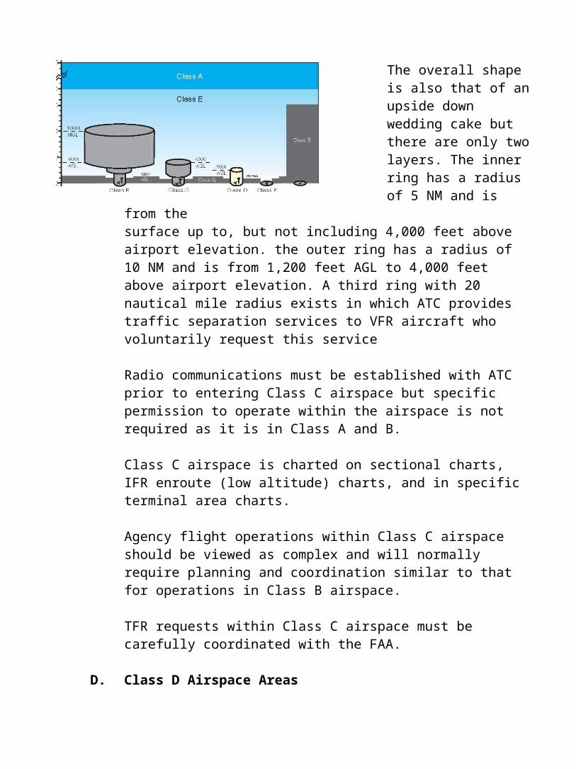
C. Class C Airspace Areas
This airspace surrounds the busy airports of mid-sized cities with a large number of commercial flight operations as well as some military airports. An operating control tower at the primary airport and radar services are key components of Class C airspace.
The overall shape is also that of an upside down wedding cake but there are only two layers. The inner ring has a radius of 5 NM and is from the

surface up to, but not including 4,000 feet above airport elevation. the outer ring has a radius of 10 NM and is from 1,200 feet AGL to 4,000 feet above airport elevation. A third ring with 20 nautical mile radius exists in which ATC
provides traffic separation services to VFR aircraft who voluntarily request this service
Radio communications must be established with ATC prior to entering Class C airspace but specific permission to operate within the airspace is not required as it is in Class A and B.
Class C airspace is charted on sectional charts, IFR enroute (low altitude) charts, and in specific terminal area charts.
Agency flight operations within Class C airspace should be viewed as complex and will normally require planning and coordination similar to that for operations in Class B airspace.
TFR requests within Class C airspace must be carefully coordinated with the FAA.
D. Class D Airspace Areas
This airspace is applied to airports with operating control towers but where the traffic volume does not meet Class C or Class B standards. Traffic usually lacks the heavy jet transport activity but often includes a complex mix of general aviation, turbo prop and business jet traffic. Radar service is often available.

The above airport elevation shape is a five nautical mile radius surrounding an operational control tower from the surface up to, but not including, 2,500 feet AGL. Class D airspace may have one or more extensions to accommodate IFR traffic. Where radar service is available ATC will provide separation service to IFR traffic and to participating VFR traffic. All traffic must maintain radio communication with the tower or have prior arrange-ments for operating within the Class D airspace. Class D airspace is charted on sectional charts, IFR enroute (low altitude) charts.
Agency flight operations commonly involve Class D airspace and must be coordinated by the control tower. Managers should remember that a large number of civilian and military flight training occurs in and around Class D airspace. It is also important to consider that radar service may not be available.
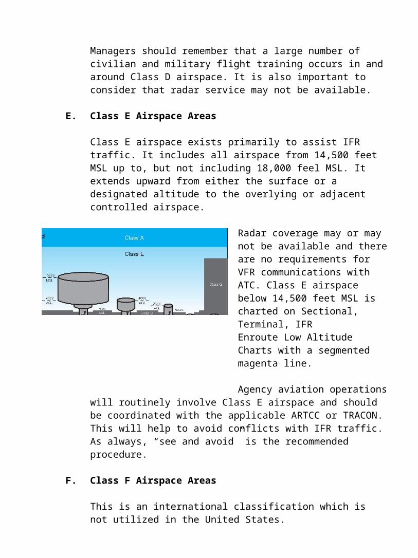
E. Class E Airspace Areas
Class E airspace exists primarily to assist IFR traffic. It includes all air-space from 14,500 feet MSL up to, but not including 18,000 feel MSL. It extends upward from either the surface
or a designated altitude to the overlying or adjacent controlled airspace.
Radar coverage may or maynot be available and there are no requirements for VFR communications with ATC. Class E airspace below 14,500 feet MSL is charted on Sectional, Terminal, IFR Enroute Low Altitude Charts with a segmented magenta line.
Agency aviation operations will routinely involve Class E airspace and should be coordinated with the applicable ARTCC or TRACON. This will help to avoid conflicts with IFR traffic. As always, “see and avoid” is the recommended procedure.

F. Class F Airspace Areas
This is an international classification which is not utilized in the United States.
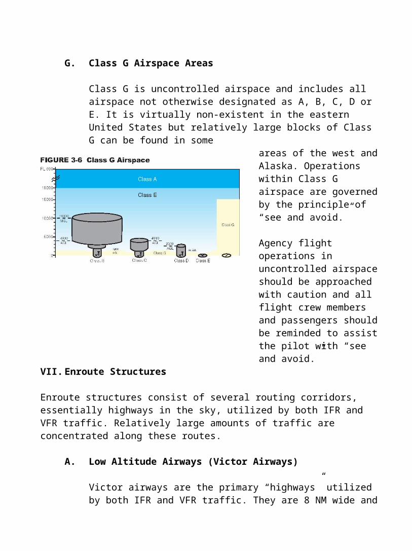
G. Class G Airspace Areas
Class G is uncontrolled airspace and includes all airspace not otherwise designated as A, B, C, D or E. It is virtually non-existent in the eastern United States but relatively large blocks of Class G can be found in some
areas of the west and Alaska. Operations within Class G airspace are governed by the principle of “see and avoid.”
Agency flight operations in uncontrolled airspace should be approached with caution and all flight crew members and passengers should be reminded to assist the pilot with “see and avoid.”
VII. Enroute Structures
Enroute structures consist of several routing corridors, essentially highways in the sky, utilized by both IFR and VFR traffic. Relatively large amounts of traffic are concentrated along these routes.
A. Low Altitude Airways (Victor Airways)
Victor airways are the primary “highways” utilized by both IFR and VFR traffic. They are 8 NM wide and generally range from 1,200 feet AGL up to but not including 18,000 MSL. The airway floor varies to ensure that aircraft operating on the airway remain clear of ground obstructions and have the ability to receive the radio signals from the navigational facilities.
They are depicted on sectionals as blue shaded lines with a “V” (hence the term “victor”) followed by a number (i.e. V-500, see Figure 3-7).
B. Jet Routes
Jet routes serve the same function as the above low altitude airways except that they are found between 18,000 MSL and to 45,000 MSL. Traffic on a jet route is always IFR designated and is managed by air traffic control. Jet routes are shown on the high altitude charts as a gray line and are represented by the letter “J” followed by a number. Jet routes are normally not of much concern to land management agencies except in a few western areas with very high terrain.
C. VFR Flyway
These are general routes for VFR traffic wishing to fly through, or near Class B airspace. The intent is to provide VFR aircraft with a way to transition the airspace. An air traffic control clearance is not required to utilize a flyway. Flyways may be charted on the back of terminal area charts but may also be used locally based on word of mouth. The best way to determine if a flyway exists locally is to ask the ATC facility controlling the Class B airspace area.
D. VFR Transition Routes
These are similar to VFR flyways and are used to accommodate VFR traffic transitioning certain Class B airspace. The difference from a VFR flyways is that a clearance is required from air traffic control and radar separation service is always provided. VFR transition routes are identified by a notation on terminal area charts.
E. Air Traffic Control Assigned Airspace (ATCAA)
ATCAAs were established to permit the continuation of MOA activities above 18,000’ MSL. From the standpoint of the MOA “user,” MOA and ATCAA are combined into one piece of airspace, with 18,000’ MSL acting as an administrative boundary.

Usually, the ATCAA is activated concurrently with the MOA. VFR aircraft are permitted to enter a MOA, but are not permitted to enter most ATCAAs because they are not permitted to fly VFR above 18,000’ MSL. MOAs are depicted on aeronautical charts, but ATCAAs are not depicted.
F. VFR Waypoints Chart Program FIGURE 3-8 Example of a VFR Waypoint
The VFR Waypoint Chart program was VPXYZ established to provide VFR pilots with a supplemental tool to assist with position awareness. The program is designed to enhance safety, reduce pilot deviations and provide navigation aids for pilots unfamiliar with an area in or around Class B, Class C and Special Use Airspace. The name of a VFR waypoint (for computer entry and flight plans) consists of five letters beginning with “VP.” VFR waypoints will be portrayed on sectionals as a four point star symbol. VFR Waypoints co-located with Visual Check Points on the sectional will be identified by small magenta flag symbols. Each VFR Waypoint name will appear in parentheses adjacent to the geographic location on the chart.
G. Maximum Elevation Figure (MEF)
Within each grid on a sectional is a large blue number followed by a smaller number, for example 61. This represents the highest elevation (including terrain and other vertical obstacles such as towers,etc.) within each square. The designation of 61 translates to 6,100’ MSL. Agency personnel need to take MEF into account when planning a TFR.
VIII. Special Use Airspace (SUA)
This special designation is designed to alert users about areas of military activity, unusual flight hazards, or national security needs, and to segregate that activity from other airspace users to enhance safety. While most SUAs involve military activity, others involve civilian users such as the Department of Energy.
Special Use Airspace is established by the FAA. Detailed information regarding the process for establishing SUA and other types of airspace is contained in FAA
Handbook 7400.2, Procedures for Handling Airspace Matters. The DoD flight information publication AP/1A contains detailed information about current SUA.
There are six different kind of SUAs as shown in Figure 3-10.
FIGURE 3-10 Categories of Special Use Airspace
PROHIBITED AREAS
RESTRICTED AREAS
WARNING AREAS
MILITARY OPERATIONS AREAS
ALERT AREAS
CONTROLLED FIRING AREAS

FIGURE 3-11 Prohibited Areas
A. Prohibited Areas (PA)
Prohibited areas are established over sensitive ground facilities such as the White House, Camp David, presidential homes, etc. (see Figure 3-9). The dimensions of the prohibited area vary. All aircraft are prohibited from flight operations within a prohibited area unless specific prior approval is obtained from the FAA or the controlling agency. Prohibited areas are charted on sectionals, IFR enroute charts, and terminal area charts.They are identified by FIGURE 3-12 Example of a Prohibited the letter “P” followed Area on a Sectionalby a number
Many agency personnel are familiar with the Boundary Waters Canoe Area in Minnesota which is a Prohibited Area by Executive Order. President Truman issued Executive Order 10092 on December 17, 1949, establishing

an airspace reservation of certain areas of the Superior National Forest. The order prohibited, with few exceptions, flight below 4,000 MSL over designated areas.
Agency personnel can not plan any operations into a PA unless special authorization has been granted by the FAA or controlling agency.
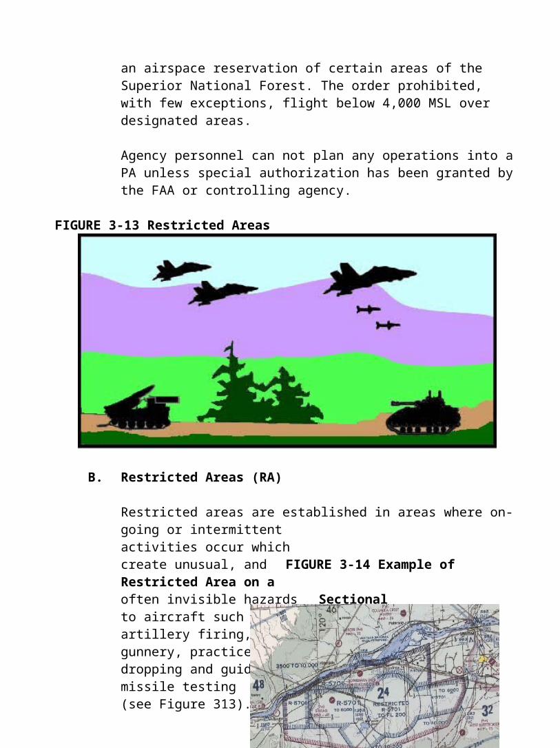
FIGURE 3-13 Restricted Areas
B. Restricted Areas (RA)
Restricted areas are established in areas where on-going or intermittent activities occur which create unusual, and FIGURE 3-14 Example of Restricted Area on aoften invisible hazards Sectional to aircraft such as artillery firing, aerial gunnery, practice bombdropping and guided missile testing (see Figure 313). Dimensions of the restricted area vary depending upon the needs of the activity and the risks to aircraft.

Restricted areas differ from prohibited areas in that most RAs have specific hours of operation and entry during these hours requires specific permission from the FAA or the controlling agency. In addition, there may be a separate scheduling agency who must also grant permission. Agency personnel must understand that hazardous flight activity is occurring in the RA when it is active.
Restricted areas are charted on sectionals, IFR FIGURE 3-16 Example of IAMs/CAHISenroute charts, and Restricted and Warning Areaterminal area charts. They are identified by the letter “R” followed by a number (see Figure 3-14). The floor and ceiling, operating hours, and controlling agency for each restricted area can be found in the chart legend.
Figure 3-17 displays an example from the Special Use Airspace Table on a

sectional. In this example, each Restricted Area is described with its identi-fication number, location, altitude, time of use and the controlling agency.
This is one reason why it is critical that each office that has coordination responsibilities or airspace have current copies of all sectionals for their area of responsibility.
FIGURE 3-17 Example of Special Use Airspace Table (Restricted Areas) from a Sectional Legend SPECIAL USE AIRSPACE ON SEATTLE SECTIONAL CHART Unless otherwise noted, altitudes are The word “TO” an altitude means “To and including.” MSL and in feet and Time is local. “MON-FRI” indicates “Monday thru Friday” Contact nearest FSS for information. FL - Flight level **Other time by NOTAM, contact FSS. NO A/G - No air to ground communications U.S. P-PROHIBITED, R-RESTRICTED, A-ALERT, W-WARNING, MOA-MILITARY
OPERATIONS AREA
*Altitudes indicate floor of MOA. All MOAs extend to but do not include FL 180 unless otherwise indicated in tabulation or on chart. ** Other time by notam--CONTACT fss ***ZSE - Seattle (This chart is for illustration only. Consult current sectional for navigational information.)
CONTROLLING NUMBER
LOCATION ALTITUDE* TIME OF USE ** AGENCY***
R-5701
BOARDMAN, OR SEE FACE OF CHART 0730-2359 MON-FRI ZSE CNTR
**6 HRS IN ADVANCE
R-5704
HERMISTON, OR TO NOT 0900-1700 MON-THU NO A/G
INCLUDING 4000
R-5706
BOARDMAN, OR 3500 TO 10,000 0730-2359 MON-FRI ZSE CNTR
**6 HRS IN ADVANCE
R-6701
ADMIRALTY INLET, WA TO 5000 INTERMITTENT BY
NOTAM NAS WHIDBEY
**2 HRS IN ADVANCE
ISLAND APP CON
R-670 FORT LEWIS, WA TO 14,000 0700-2300 MON-FRI SEATTLE

FIGURE 3-18 Military Operations Area
C. Military Operations Areas (MOA)
A MOA is an area of airspace designated for military training activities (see Figure 3-18). MOAs were established to contain certain military activities such as air combat maneuvers, intercepts, acrobatics, etc. Civilian VFR flights are allowed within a MOA even when the area is in use by the military. Air traffic control will separate IFR traffic from military activity. A clearance is not required for VFR operations.
* Altitudes indicate floor of MOA. All MOAs extend to but do not include FL 180 unless otherwise indicated in tabulation or on chart. ** Other time by NOTAM - contact FSS *** ZSE - Seattle (This chart is for illustration only. Consult current sectional for navigational information.)
FIGURE 3-19 Example of a MOA Chart Table from a Sectional
MOA Name
Altitude of Use*
Time of Use ** Controlling
Agency*** BOARDMAN 4,000 0730-2359 MON-FRI ZSE CNTR
** 6 HRS IN ADVANCE CHINOOK A,B 300 TO 5,000 SUNRISE-SUNSET NAS WHIDBEY
ISLAND APP CON
OKANOGAN 9,000 CONTINUOUS DAYLIGHT ZSE CNTR OKANOGAN B,C
300 AGL TO BUT NOT
INTERMITTENT BY NOTAM ZSE CNTR
INCLUDING 9,000 OLYMPIC A,B 6,000 BY NOTAM ZSE CNTR RAINIER 1,2,3 2,000 TO 9,000 INTERMITTENT BY
NOTAM SEATTLE-TACOMA APP CON
ROOSEVELT A 9,000 INTERMITTENT BY
NOTAM ZSE CNTR ROOSEVELT 300 AGL TO BUT INTERMITTENT BY ZSE CNTR

Users may encounter high-speed military aircraft involved in flight training, acrobatic or abrupt flight maneuvers and formation flying often at speeds greater than 250 Knots Indicated Air Speed (KIAS). Military pilots conducting training within an active MOA are exempt from the provisions of the Federal Aviation Regulations prohibiting acrobatic flight within federal airways and control zones. They are also exempt with respect to the Federal Aviation Regulations for flights at speeds in excess of 250 knots below 10,000 feet MSL.
MOAs have a defined floor and ceiling which can range up to the floor of Class A airspace (18,000 feet). MOAs are identified by a specific name, the letters “MOA”, and are charted in magenta on sectionals, IFR enroute charts, and terminal area charts. MOA dimensions, hours of use, and controlling agency can be found in the chart legend (see Figure 3-19).
FIGURE 3-21 Illustration of stacked MOAs

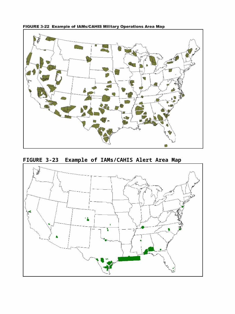
FIGURE 3-23 Example of IAMs/CAHIS Alert Area Map
Agency personnel should note that MOAs can be “stacked” on top of each other (see Figure 3-21). The status of a MOA can change rapidly and should be checked frequently when agency flight operations are occurring.
MOA’s will have a scheduling agency responsible for scheduling all military flights intending to use the airspace. If the scheduling agency does not have a continuous point of contact, then an alternate scheduling agency will be designated. Consult the AP1/A for scheduling MOA information.
It is strongly recommended that communications be established with the controlling agency of any MOA in proximity to agency flight operations, even if the MOA is not active. At a minimum, pilots should contact air traffic control prior to entering an MOA to get the most current status information.
D. Alert Areas (AA)
Alert areas may contain a high volume of pilot training or an unusual type of aerial activity (see Figure 3-25). There are no special requirements for
FIGURE 3-25 Alert Areas

FIGURE 3-26 Example of an Alert Area on a operations within alert areas, otherSectional than heightened vigilance. All
operations must be in compliance with the Federal Aviation Regulations. The types of flying involved could be military, aircraft manufacturers or a high concentration of flights (i.e. helicopter activity near oil rigs).
Alert Areas are depicted by defined areas marked with the letter “A” followed by a number (see Figure 3-26). Alert area dimensions differ for each area and are depicted on sectional charts, IFR enroute charts, or terminal area charts.
E. Warning Areas (WA)
Warning areas contain the same kind of hazardous flight activity as re-stricted areas but have a different title since they are located offshore over domestic and international waters (see Figure 3-27). Examples of likely hazards include artillery firing, aerial gunnery, guided missile exercises and fighter interceptions.
Warning areas generally begin three miles offshore. Executive Order 10854 extends the application of the Federal Aviation Act of 1958, as
FIGURE 3-27 Warning Areas

FIGURE 3-28 Warning Area from Sectional amended, to the overlying airspace of those areas of land or water outside the United States beyond the 12mile offshore limit. It includes areas that the United States has appropriate jurisdiction or control under international treaty agreement.
Warning areas overlying the territorial waters of the United States are under FAA jurisdiction. However, any airspace action, rulemaking or nonrulemaking that concerns airspace beyond the 12-mile offshore limit requires coordination with the Departments of Defense and the adjacent State. Although VFR operations are permitted in warning areas, the FAA does not guarantee traffic separation and agency personnel should carefully weigh the risks of such operations.

Warning areas are represented on sectionals, IFR enroute charts and some terminal area charts. They are depicted by a “W” with a number following it (see Figure 3-28). Dimensions for each warning area can be determined by consulting the appropriate chart legend.
F. Controlled Firing Areas (CFA)
Controlled firing areas contain civilian and military activities which, if not contained, could be hazardous to “non participating” aircraft (see Figure 3-30). These include rocket testing, ordinance disposal, small arms fire, chemical disposal, blasting, etc. CFAs are differentiated from MOAs and restricted areas in that radar or a ground lookout is utilized to indicate when an aircraft might be approaching the area. All activities are then suspended. The FAA does not chart CFAs because a CFA does not require a nonpar-ticipating aircraft to change it’s flight path. Agency personnel may find information about CFAs from the nearest regional FAA headquarters.
FIGURE 3-30 Controlled Firing Areas
IX. Military Training Routes (MTR)
Military training routes are designed for low level, high-speed terrain following training missions. These routes are provided for military training at speeds of more than 250 knots and at altitudes that range from ground level (surface) to 18,000 feet, though most operations are conducted well below 10,000 feet MSL.

There are more than 500 routes, roughly divided in half for VFR and IFR operations. They pose flight hazards to any uncoordinated aviation mission within their perimeters.
FIGURE 3-32 MTR Number Assignments Chart
Region
MTR Numbers with One or More Segments Above 1,500 Feet
AGL MTR Numbers For All Routes At
Or Below 1,500 Feet AGL
Southern 001 thru 099 1001 thru 1099
Southwest 100 thru 199 1100 thru 1199
Western-Pacific 200 thru 299 1200 thru 1299
980 thru 999 1980 thru 1999
Northwest Mountain 300 thru 499 1300 thru 1499
Central 500 thru 599 1500 thru 1599
Great Lakes 600 thru 699 1600 thru 1699
Eastern 700 thru 799 1700 thru 1799
New England 800 thru 899 1800 thru 1899 Alaska 900 thru 979 1900 thru 1979


The AP/1B provides a complete description of the MTR’s to include the originating/scheduling activity, the hours of operation, the geographical points of each segment, the altitude limitations for each segment, the route width, special operating procedures, and the Flight Service Stations within 100 NM that have current information.

FIGURE 3-35 Side view of MTR flight corridor
Consult the legend (Figure 3-33) inthe AP/1B Chart for an explanation of other symbols. Additional symbols will indicate entry/exit points for military aircraft, turning points, departure routes, etc. In addition to charted route altitudes, additional restrictions or changes in width may be imposed to avoid sensitive areas or other conditions of use. These restrictions are published in the AP/1B under the standard operating procedures (SOPs) for each route.
A. Basic Information About Military Training Routes
MTR’s are depicted on sectionals as a solid gray line and a letter/ number identifier.
Course widths may vary between three NM to 20 NM either side of the gray reference line as depicted on the sectional.
IR indicates the route is flown under IFR, regardless of weather conditions.
VR indicates the route is flown under VFR requiring minimum visual meteorological conditions.
IR or VR routes that include one or more segments above 1,500’ AGL are identified by three numbers (i.e. VR 206)
IR or VR routes with no segment above 1,500’ are identified by four numbers (i.e. VR1305)
Routes are flown one way, however the same route flown in the opposite direction will have a separate distinct number.
B. Corridor Height (Route Floor and Ceiling)
Each route segment of an MTR is allocated a floor and ceiling altitude (see Figure 3-35). The floor may be at the earth’s surface or at any altitude above the surface. Route segment altitudes are published in the AP/1B
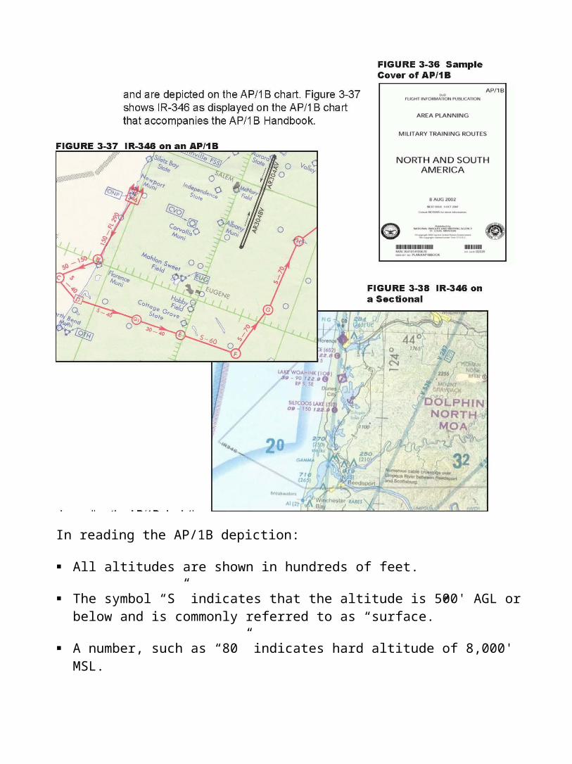
In reading the AP/1B depiction:
All altitudes are shown in hundreds of feet.
The symbol “S” indicates that the altitude is 500' AGL or below and is commonly referred to as “surface.”
A number, such as “80” indicates hard altitude of 8,000' MSL.
“S-40” indicates a lower and upper surface separated by a hyphen. For example S40 indicates a floor of 500' AGL or below (e.g. surface) and a ceiling of 4,000' MSL.
The numbers “30-40” indicates a floor of 3,000' AGL and a ceiling of 4,000' MSL.
For MTR descriptions, the floor is generally described in AGL and the ceiling in MSL.
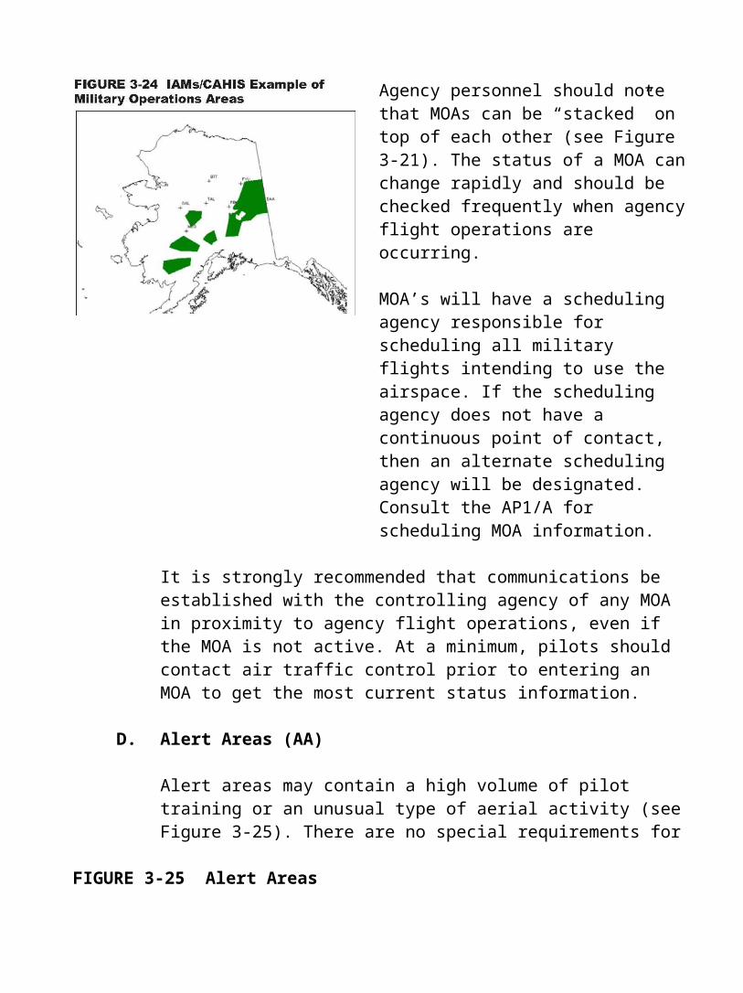
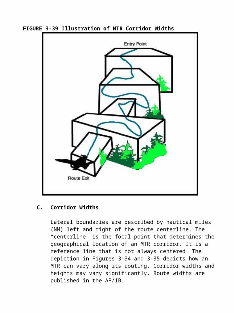
FIGURE 3-39 Illustration of MTR Corridor Widths
C. Corridor Widths
Lateral boundaries are described by nautical miles (NM) left and right of the route centerline. The “centerline” is the focal point that determines the geographical location of an MTR corridor. It is a reference line that is not always centered. The depiction in Figures 3-34 and 3-35 depicts how an MTR can vary along its routing. Corridor widths and heights may vary significantly. Route widths are published in the AP/1B.
Figure 3-40 displays the AB/1B text description of the route width for VR176. This particular MTR can be at times 47 miles wide. Note the variation in route width as described.


D. Maneuver Areas/LOWAT
An MTR may have a designated segment where DoD aircraft may perform various maneuvers dictated by operational requirements. Aircraft may freely maneuver within the lateral and vertical confines of the MTR segment before resuming flight on the remainder of the route.
There are also designated areas within an MTR that indicate alternate exits and entrances. This accommodates a training mission that might require use of an MOA or an airport.
Low Altitude Air to Air Training (LOWAT) refers to maneuvers within MTR’s for the purpose of simulating an aerial attack and defense response. These areas are designated in AP/1B.
E. MTR Coordination
Flight planning should take into account the existence of these routes and the in-flight risks they pose.
If a mission is in the vicinity of an MTR, look at the DoD AP/1B to decide if the route segment altitude will affect the flight plan. Dispatch organizations should have copies of AP/1B’s and accompanying charts.
Pilots may contact the nearest FSS with position, route of flight and desti-nation. The FSS specialist should have information available to include times of scheduled activity, altitudes in use on each route segment and route width.
Often the FAA will only have the schedule as received from the military the night before. The FAA can provide a schedule but these schedules have been known to change. Military pilots check in prior to entry on IR-MTR’s. However, they are not required to check in with ATC prior to entry of VR-MTR’s.

All MTRs must be scheduled through the assigned scheduling activity prior to use. There have been cases of MTR being flown without being scheduled. This is a violation of Federal Aviation Regulations (assuming excessive speed is used). All pilots are reminded that “see and avoid” still applies when flying inside an MTR.
FIGURE 3-41 Various Depictions of an MTR (not for navigational purposes)
MTR on an AP1/B Actual MTR Boundaries
MTR on a Sectional
MTR on IAMS


X. Other Military Airspace Structures
Due to the unique nature of military training operations, training and testing requirements, other airspace for special military use has been developed outside the Special Use Airspace (SUA) program. These are:
Slow Routes Low Altitude Tactical Navigation Areas (LATN) Local Flying Areas Air Refueling Routes Temporary Special Use Airspace (TSUA) National Security Areas (NSA) Cruise Missile Routes
A. Slow Routes (SR)
Slow speed low altitude training routes are used formilitary air operations flown from the surface up to 1500' AGL at air speeds of 250 KIA or less. SR-359 is shown in Figure 3-43. Route widths are published in individual route descriptionsin the AP/1B and may vary. Slow routes technically are not considered MTRs. High speed aircraft are notallowed to use slow routes. Generally, the routes are utilized by the Air Force. Many of the routes are flown by cargo aircraft, such as C-141s, that use drop zones for military training purposes. There are about 200 Slow Routes in the United States. They are represented on the AP/ 1B charts and are depicted by a black line. They are not charted on sectionals.

FIGURE 3-45 Slow Route

B. Low Altitude Tactical Navigation Areas (LATN)
LATNs are large, clearly defined geographical areas wherein the Air Force practices random tactical navigation that typically ranges from surface to 1,500 feet AGL. These areas are not charted. Current information con-cerning LATNs is available from local Air Force facilities. These areas are flown at or below 250 KIAS, when multiple aircraft are not flying the same ground track. MOA acrobatic type activity is not appropriate for a LATN area.
C. Local Flying Areas
Most military facilities develop local flying areas within which they can conduct routine, non-hazardous training activity. These areas are normally developed in conjunction with local FAA controllers and airspace managers and are developed so they will not conflict with other airspace usage.

They are locally published and although dissemination of these areas is generally limited to assigned units, the airbase airspace managers will make them available to interested parties. These areas are not depicted on standard published charts or publications.
FIGURE 3-49 Two Types of Aerial Refueling Routes: High Level and VFR Helicopter Refueling Routes

D. Aerial Refueling Routes
There are over 100 Aerial Refueling Routes utilized by the military over the United States. The majority of them are located at high altitudes that pose no hazard to agency operations. However, there are VFR helicopter refueling tracks at low altitudes that do affect operations at lower altitudes (see Figure 3-49). The information about the VFR refueling tracks is located in Chapter 4 of the AP/1B and are represented on the AP/1B chart by double black lines.
There are four types of Aerial Refueling Tracks:
Track 2- 400 miles long Anchor 20-50 miles long, holding pattern associated
with a MOA or RA Special Anytime, anywhere (e.g. emergency, military
exercises) LAAR Low Altitude Air Refueling Route (below 3000’
AGL)
Some VFR refueling routes are designed to be flown at or below 1,500 feet AGL. They are designed to permit aircraft flying the route to avoid
FIGURE 3-51 Helicopter Refueling Route from AP/1B

(This chart is for illustration only. Consult current sectional for navigational information.)FIGURE 3-52 Example of a Temporary MOA Notice (Dinger 1-5 Jan 8-Feb 21, 2003)
charted, uncontrolled airports by three NM or 1,500 feet. The track is nor-mally 50-100 NM long and normally four NM in width either side of a centerline unless otherwise specified.

Aerial refueling may be conducted within SUA assigned altitude. This includes both low altitude (Helicopter and fixed wing) refueling as well as higher altitude tracks. Figures 3-50 and 3-51 depict AP/1B chart references to aerial refueling routes.
E. Temporary Special Use Airspace
The military and the FAA have the ability to create Temporary Military Operations Areas or Temporary Restricted Areas to accommodate the specific needs of a particular military exercise (see Figure 3-52). This information is available via either the NOTAM system or by direct contact with the FAA Regional Headquarters.
Temporary military operating areas are published in the “NOTICES TO AIRMEN” publication. This publication may be purchased on a subscription basis from the Government Printing Office (GPO) in Washington, D.C. (or found at http://www.faa.gov/ntap).
F. Cruise Missile Routes FIGURE 3-53 Cruise Missile Routes
Cruise missile operations are conducted on selected IR Military Training Routes. They may be flown in excess of 250 knots and below 10,000 MSL. Cruise missiles may be accompanied by two chase aircraft escort. The chase aircraft must always maintain the ability to maneuver the missile out of the flight path of conflicting traffic. A high altitude communications aircraft may be used in conjunction with the cruise missile and maintains communication and radar contact with the appropriate ATC facility.
Cruise missile operations are conducted in daylight hours under VFR conditions, with flight visibility of at least five miles, 2,000 feet horizontal and 1,000 feet vertical separation from clouds. Special charting on a sectional designates unmanned aerospace vehicle routes (UAVRS). Two well-known routes are in southern California and Florida. Figure 3-53 depicts a cruise missile corridor.
G. National Security Areas (NSA)
National Security Areas are areas where there is a requirement for in-creased security (see Figure 3-54). Pilots are requested to voluntarily avoid flying through the depicted NSA. When it is necessary to provide a greater level of security and safety, flights in NSAs may be temporarily prohibited under the provisions of the Federal Aviation Regulation Part 99.7.
NSAs are depicted on aeronautical charts with a broken magenta line. Aircraft are requested to remain clear of these areas. Check NOTAMs for regulatory restrictions.

Since the tragedies of FIGURE 3-54 National Security Area September 11, 2001, special security measures have been implemented within the United States. Pilots are advised to avoid the airspace above, or in proximity to, sites such as nuclearpower plants, power plants, dams, refineries, industrial complexes, military facilities and other similar facilities. Pilots should not circle as to loiter in thevicinity of such facilities. As always, pilots should check with the FAA for current NOTAMs.
H. Air Defense Identification Zone (ADIZ)
All aircraft entering FIGURE 3-55 Example of Washington DC ADIZ domestic U.S. airspace frompoints outside must provide identification prior to entry. To facilitate early aricraft identification of all aircraft in the vicinity of the U.S. and international airspace boundaries, Air Defense Identification Zones (ADIZ) have been established. Generally for all flights entering an ADIZ the following will occur:
A flight plan will be filed An operating two-way radio is required Aircraft will be equipped with an operable radar beacon transponder
that has altitude reporting capability
ADIZ are normally located “off shore” or along the U.S. boundaries, however in response to threat levels, ADIZ have been created over Washington DC and New York City.
XI. Special Conservation Areas
A. Environmentally Sensitive Areas
There are areas of airspace in the United States that are considered environmentally sensitive. The physical presence or noise associated with aircraft overflight may conflict with the purpose of environmentally sensi-tive areas. Examples of these areas include wilderness areas, national parks, areas with threatened and/or endangered species, religious areas, wildlife refuges, Native American areas or primitive areas.
Pilots are voluntarily requested to maintain a minimum altitude of 2,000 feet above the surface of the following: National Parks, Monuments, sea-shores, lake shores, recreation areas and scenic river ways administered by the NPS, National Wildlife Refuges, Big Game Refuges, Game Ranges and Wildlife Ranges administered by the FWS; wilderness and primitive areas administered by the USFS. References may be found in the Airmens Information Manual (AIM) in 7-4-6. There is also a reference printed on the inside of each Sectional.
The 2,000-feet advisory is based on “Visual Flight Rules (VFR) Flight Near Noise-Sensitive Areas” (Advisory Circular 91-36c), which defines the surface as the highest terrain within 2,000 feet laterally of the route of flight or the upper most rim of a canyon or valley.
The landing of aircraft is prohibited on lands or waters administered by the National Park Service, U.S. Fish and Wildlife Service, or U.S. Forest Service without authorization from the respective agency. The following, taken from NOAA sectional, are exceptions:
When forced to land due to an emergency beyond the control of the operator,
At officially designated landing sites, or On approved official business of the Federal Government.

FIGURE 3-57 Sectional Reference Regarding 2000’ Advisory
B. Air Drops
Federal regulations also prohibit airdrops (by parachute or other means) of persons, cargo, or objects from aircraft on lands administered by the three agencies without authorization from the respective agency. Exceptions include:
Emergencies involving the safety of human life, or Threat of serious property loss.

C. Special Federal Aviation Regulation (SFARs)
Federal statutes prohibit certain types of flight activity and/or provide alti-tude restrictions over designated National Wildlife Refuges, National Parks, and National Forests. Examples of these designated area are: Boundary Waters Canoe Wilderness Areas, Minnesota; Haleakala National Park, Hawaii; Yosemite National Park, California; and Grand Canyon National Park, Arizona. These areas are represented on sectional charts.
D. Noise Abatement Procedures
Civilian and Department of Defense airfields may have published noise abatement procedures in their Class C-E airspace or transition routes. They may only be published by the local airport manager or noise abatement officer. Concentrated VFR traffic along these routes may result in increased mid-air potential. When operating out of an unfamiliar airport, it is recommended that pilots check with the manager to become familiar with procedures and restrictions.
SUA and MTRs also may impose noise abatement procedures on their users. Check AP/1A, AP/1B or contact the using/scheduling agency for specific information.
XII. Federal Aviation Regulations of the Code of Federal Regulations (14 CFR)
Although most people in the aviation industry understand the informal use of the acronym “FAR” as pertaining to the requirements of Title 14 of the Code of Fed-eral Regulations (14 CFR), it is not correct. The acronym FAR is an abreviation for Federal Acquisition Regulations. The FAA uses CFR when referring to the Code of Regulations. For Title 14, it appears as 14 CFR.
To successfully operate within the NAS it is necessary to have a basic under-standing of the regulations and their structure. A complete listing of the regulations would require more room than this guide allows and would include a great deal that is not applicable to needs of the land management agencies. Listed below are sections of the 14 CFR that may be applicable to land management agencies. Complete text may be accessed through a link to the FAA in Appendix B.

A. Part 11 General Rulemaking Procedures
Part 11 prescribes the procedures to be followed in the initiation, adminis-trative processing, issuance and publication of rules, regulations, and FAA orders.
B. Part 71 Airspace, Designation of Class A, Class B, Class C, Class D and ClassE Airspace Areas; Airways; Routes; and Reporting Points
Part 71designates the airspace structure including airspace classes, airways; routes; and reporting points.
C. Part 73 Special Use Airspace
Part 73 designates special use airspace and prescribes the requirements of the use of that airspace.
D. Part 77 Objects Affecting Navigable Airspace
Part 77 established standards for determining obstructions in the navigable airspace and sets forth requirements for notice to the FAA Administrator of certain proposed construction or alteration. It provides for aeronautical studies and public hearings to determine the effects of such proposals on the navigable airspace.
E. Part 91 Air Traffic and General Operating Rules
Part 91 prescribes general operating and flight rules governing the opera-tion of aircraft within the United States and governing operation of U.S. registered aircraft outside of the United States. Sub-sections of part 91 that may be of particular importance to land management agencies are:
1. 14 CFR Careless Or Reckless Operation 2. 14 CFR Operating Near Other Aircraft 3. 14 CFR Right Of Way Rules (Except Water Operations) 4. 91.119 Minimum Safe Altitudes
F. Part 93 Special Air Traffic Rules and Airport Traffic Patterns
Part 93 prescribes special air traffic rules and airport traffic patterns.

G. Part 95 IFR Altitudes
Part 95 prescribes altitudes governing the operation of aircraft under IFR on federal airways, jet routes, area navigation low or high routes. It also designates mountainous areas and changeover points.
H. Part 135 Operating Requirements: Commuter and On-demand Operations and Rules Governing Persons on Board Such Aircraft
Part 135 establishes additional operating standards and flight rules for commercial aircraft such as charter services and air tour operators.
I. Part 137 Agriculture Aircraft Operations
Part 137 prescribes rules governing agricultural operations within the United States.
J. Part 157 Notice of Construction, Alteration, Activation and Deactivation of Airports
Part 157 pertains to the Notice requirements for proposals involving con-struction, alteration, activation and deactivation of civil and joint use (civil-military) airports. It also provides for aeronautical studies to determine the effects of such proposals on the safe and efficient use of airspace.