channels 4/3/2 - bill's web space type atc spade -2@40a speaker short, short to +12v, and short...
TRANSCRIPT


Below is a basic trouble-shooting guide to assist in seeking out and correcting a problem that may occur in the installationprocess. Although lengthy, this chart cannot address every single problem possible but mainly the ones most common.
PARAMETER/FEATURE PA4100
Channels 4/3/2
Size ( W x H x D) 10.4 x9.8x2.6 inches (265x250x67mm)
Weight (with housing) 6.0 lbs (2.7 kg)
Crimping style speaker terminals? YES
Maximum terminal wire size 10 ga.
Subsonic filter YES (10 Hz)
Separate front/rear or left/right gains? F/R YES, L/R NO
Fuse Type ATC spade -2@40A
Speaker short, short to +12V, and short to ground protection? YES
High, low, and reverse voltage protection? YES
Power output transistors MOSFET
Switching power supply transistors MOSFET
Minimum speaker impedance (non-bridged) 2 ohms
(bridged) 4 ohms
PERFORMANCE DATA
Rated power output @ 0.1% THD, 13.8V
4 channels into 4 ohms / 2 ohms 4 x 100 W / 4 x 125 W
2 channels into 4 ohms 2 x 250 W
Total Harmonic Distortion @ rated full output 0.03% THD
Rated Signal/Noise ratio (averaged value)
Measured @ 1 watt / 1 kHz dBA 82
Measured @ full rated power (0.1% THD) dBA >100
Damping factor >100
Frequency response (full-range mode) 20 - 50,000 Hz
High-pass crossover frequency limits 50 H z - 250 Hz (variable), 12dB/oct
Low-pass crossover frequency limits 50 H z - 250 Hz (variable), 12dB/oct
Input impedance 10 kohms
Input signal voltage control range 0.3 - 6.0 vrms
Current Draw @ 13.8 VDC (typical values @ X watts / Efficiency %)
@ full rated power, bridged mode (@ 4 ohms) 70 A (65%)
@ full rated power, unbridged (@ 4 ohms) 42 A (78%)
@ 33% rated power, unbridged (@ 4 ohms) 16 A (60%)
@ 10% rated power, unbridged (@ 4 ohms) 8 A (40%)
@ idle (@ 4 ohms) 2.5 A
Minimum battery voltage to maintain rated power 12.6 VDC
Usable battery voltage 10 - 16 VDC
Trigger line voltage range 10 - 16 VDC
Trigger line current draw @ 20 mA
Turn on delay time @ 2.0 seconds
Thermal shutoff temperature (average heat-sink temp) @ 85˚ C (185˚ F)
NOTE: DUE TO ONGOING PRODUCT IMPROVEMENTS, DESIGN AND SPECIFICATIONS ARE SUBJECT TO CHANGEWITHOUT ADVANCED NOTICE TO THE CONSUMER OR RETAILER.
BLAUPUNKT SPECIFICATIONS - PA4100 4/3/2 CHANNEL AMPLIFIER

What is an amplifier? . . . . . . . . . . . . . . . . . . . . . . . . . . . . . . . . . . . . . . . . . . . . . . . . . . . . . . . . . . . . . . . . . . . . . . . . . . . . . . . . . . .2Key features . . . . . . . . . . . . . . . . . . . . . . . . . . . . . . . . . . . . . . . . . . . . . . . . . . . . . . . . . . . . . . . . . . . . . . . . . . . . . . . . . . . . . . . . . .2Safety Concerns & installation warnings . . . . . . . . . . . . . . . . . . . . . . . . . . . . . . . . . . . . . . . . . . . . . . . . . . . . . . . . . . . . . . . . . . .3System planning . . . . . . . . . . . . . . . . . . . . . . . . . . . . . . . . . . . . . . . . . . . . . . . . . . . . . . . . . . . . . . . . . . . . . . . . . . . . . . . . . . . . . .4Installation tools . . . . . . . . . . . . . . . . . . . . . . . . . . . . . . . . . . . . . . . . . . . . . . . . . . . . . . . . . . . . . . . . . . . . . . . . . . . . . . . . . . . . . . .4Vehicle wiring . . . . . . . . . . . . . . . . . . . . . . . . . . . . . . . . . . . . . . . . . . . . . . . . . . . . . . . . . . . . . . . . . . . . . . . . . . . . . . . . . . . . . . . . .5Connections & controls . . . . . . . . . . . . . . . . . . . . . . . . . . . . . . . . . . . . . . . . . . . . . . . . . . . . . . . . . . . . . . . . . . . . . . . . . . . . . . .6-7System configurations 1 & 2 . . . . . . . . . . . . . . . . . . . . . . . . . . . . . . . . . . . . . . . . . . . . . . . . . . . . . . . . . . . . . . . . . . . . . . . . . . . . .8System configurations 3 & 4 . . . . . . . . . . . . . . . . . . . . . . . . . . . . . . . . . . . . . . . . . . . . . . . . . . . . . . . . . . . . . . . . . . . . . . . . . . . . .9Troubleshooting chart . . . . . . . . . . . . . . . . . . . . . . . . . . . . . . . . . . . . . . . . . . . . . . . . . . . . . . . . . . . . . . . . . . . . . . . . . . . . . . . . .10Warranty information . . . . . . . . . . . . . . . . . . . . . . . . . . . . . . . . . . . . . . . . . . . . . . . . . . . . . . . . . . . . . . . . . . . . . . . . . . . . . . . . . .11Blaupunkt technical support . . . . . . . . . . . . . . . . . . . . . . . . . . . . . . . . . . . . . . . . . . . . . . . . . . . . . . . . . . . . . . . . . . . . . . . . . . . .11Assembly & Mounting . . . . . . . . . . . . . . . . . . . . . . . . . . . . . . . . . . . . . . . . . . . . . . . . . . . . . . . . . . . . . . . . . . . . . . . . .Back Cover
TABLE OF CONTENTS
Qu’est-ce qu’un amplificateur . . . . . . . . . . . . . . . . . . . . . . . . . . . . . . . . . . . . . . . . . . . . . . . . . . . . . . . . . . . . . . . . . . . . . . . . . .12Caractéristiques principales . . . . . . . . . . . . . . . . . . . . . . . . . . . . . . . . . . . . . . . . . . . . . . . . . . . . . . . . . . . . . . . . . . . . . . . . . . . .12Consignes de sécurité et avertissements relatifs à l’ installation . . . . . . . . . . . . . . . . . . . . . . . . . . . . . . . . . . . . . . . . . . . . . . . .13Planification du système . . . . . . . . . . . . . . . . . . . . . . . . . . . . . . . . . . . . . . . . . . . . . . . . . . . . . . . . . . . . . . . . . . . . . . . . . . . . . . .14Outils d’installation . . . . . . . . . . . . . . . . . . . . . . . . . . . . . . . . . . . . . . . . . . . . . . . . . . . . . . . . . . . . . . . . . . . . . . . . . . . . . . . . . . .14Câblage du véhicule . . . . . . . . . . . . . . . . . . . . . . . . . . . . . . . . . . . . . . . . . . . . . . . . . . . . . . . . . . . . . . . . . . . . . . . . . . . . . . . . . .15Connexions & Commandes . . . . . . . . . . . . . . . . . . . . . . . . . . . . . . . . . . . . . . . . . . . . . . . . . . . . . . . . . . . . . . . . . . . . . . . . .16-17Configuration des systèmes 1 et 2 . . . . . . . . . . . . . . . . . . . . . . . . . . . . . . . . . . . . . . . . . . . . . . . . . . . . . . . . . . . . . . . . . . . . . . .18Configuration des systèmes 3 et 4 . . . . . . . . . . . . . . . . . . . . . . . . . . . . . . . . . . . . . . . . . . . . . . . . . . . . . . . . . . . . . . . . . . . . . . .19Tableau de dépannage . . . . . . . . . . . . . . . . . . . . . . . . . . . . . . . . . . . . . . . . . . . . . . . . . . . . . . . . . . . . . . . . . . . . . . . . . . . . . . . .20Garantie . . . . . . . . . . . . . . . . . . . . . . . . . . . . . . . . . . . . . . . . . . . . . . . . . . . . . . . . . . . . . . . . . . . . . . . . . . . . . . . . . . . . . . . . . . . .21Assistance technique de Blaupunkt . . . . . . . . . . . . . . . . . . . . . . . . . . . . . . . . . . . . . . . . . . . . . . . . . . . . . . . . . . . . . . . . . . . . . .21Assemblage & Montage . . . . . . . . . . . . . . . . . . . . . . . . . . . . . . . . . . . . . . . . . . . . . . . . . . . . . . . . . . . . . . . . . .Couverture de dos
TABLE DES MATIÈRES
¿Qué es un amplificador? . . . . . . . . . . . . . . . . . . . . . . . . . . . . . . . . . . . . . . . . . . . . . . . . . . . . . . . . . . . . . . . . . . . . . . . . . . . . . .22Características principales . . . . . . . . . . . . . . . . . . . . . . . . . . . . . . . . . . . . . . . . . . . . . . . . . . . . . . . . . . . . . . . . . . . . . . . . . . . . .22Consideraciones de seguridad y precauciones en la instalación . . . . . . . . . . . . . . . . . . . . . . . . . . . . . . . . . . . . . . . . . . . . . . .23Planificación del sistema . . . . . . . . . . . . . . . . . . . . . . . . . . . . . . . . . . . . . . . . . . . . . . . . . . . . . . . . . . . . . . . . . . . . . . . . . . . . . . .24Herramientas de instalación . . . . . . . . . . . . . . . . . . . . . . . . . . . . . . . . . . . . . . . . . . . . . . . . . . . . . . . . . . . . . . . . . . . . . . . . . . . .24Alambrado del vehículo . . . . . . . . . . . . . . . . . . . . . . . . . . . . . . . . . . . . . . . . . . . . . . . . . . . . . . . . . . . . . . . . . . . . . . . . . . . . . . .25Conexiones y Controles . . . . . . . . . . . . . . . . . . . . . . . . . . . . . . . . . . . . . . . . . . . . . . . . . . . . . . . . . . . . . . . . . . . . . . . . . . . .26-27Configuración de los sistemas 1 y 2 . . . . . . . . . . . . . . . . . . . . . . . . . . . . . . . . . . . . . . . . . . . . . . . . . . . . . . . . . . . . . . . . . . . . . .28Configuración de los sistemas 3 y 4 . . . . . . . . . . . . . . . . . . . . . . . . . . . . . . . . . . . . . . . . . . . . . . . . . . . . . . . . . . . . . . . . . . . . . .29Cuadro de solución de problemas . . . . . . . . . . . . . . . . . . . . . . . . . . . . . . . . . . . . . . . . . . . . . . . . . . . . . . . . . . . . . . . . . . . . . . .30Información de garantía . . . . . . . . . . . . . . . . . . . . . . . . . . . . . . . . . . . . . . . . . . . . . . . . . . . . . . . . . . . . . . . . . . . . . . . . . . . . . . .31Apoyo técnico de Blaupunkt . . . . . . . . . . . . . . . . . . . . . . . . . . . . . . . . . . . . . . . . . . . . . . . . . . . . . . . . . . . . . . . . . . . . . . . . . . .31Armadura y Montaje . . . . . . . . . . . . . . . . . . . . . . . . . . . . . . . . . . . . . . . . . . . . . . . . . . . . . . . . . . . . . . . . . . . . . . .Portada Trasera
INDICE
O que é um amplificador? . . . . . . . . . . . . . . . . . . . . . . . . . . . . . . . . . . . . . . . . . . . . . . . . . . . . . . . . . . . . . . . . . . . . . . . . . . . . .32Características-chave . . . . . . . . . . . . . . . . . . . . . . . . . . . . . . . . . . . . . . . . . . . . . . . . . . . . . . . . . . . . . . . . . . . . . . . . . . . . . . . . .32Medidas de Segurança e advertências para a instalação . . . . . . . . . . . . . . . . . . . . . . . . . . . . . . . . . . . . . . . . . . . . . . . . . . . . .33Planejamento do sistema . . . . . . . . . . . . . . . . . . . . . . . . . . . . . . . . . . . . . . . . . . . . . . . . . . . . . . . . . . . . . . . . . . . . . . . . . . . . . .34Ferramentas para a instalação . . . . . . . . . . . . . . . . . . . . . . . . . . . . . . . . . . . . . . . . . . . . . . . . . . . . . . . . . . . . . . . . . . . . . . . . . .34Fiação do veículo . . . . . . . . . . . . . . . . . . . . . . . . . . . . . . . . . . . . . . . . . . . . . . . . . . . . . . . . . . . . . . . . . . . . . . . . . . . . . . . . . . . .35Conexões e controles . . . . . . . . . . . . . . . . . . . . . . . . . . . . . . . . . . . . . . . . . . . . . . . . . . . . . . . . . . . . . . . . . . . . . . . . . . . . . .36-37Configurações 1 e 2 do sistema . . . . . . . . . . . . . . . . . . . . . . . . . . . . . . . . . . . . . . . . . . . . . . . . . . . . . . . . . . . . . . . . . . . . . . . . .38Configurações 3 e 4 do sistema . . . . . . . . . . . . . . . . . . . . . . . . . . . . . . . . . . . . . . . . . . . . . . . . . . . . . . . . . . . . . . . . . . . . . . . . .39Quadro para solução de problemas . . . . . . . . . . . . . . . . . . . . . . . . . . . . . . . . . . . . . . . . . . . . . . . . . . . . . . . . . . . . . . . . . . . . . .40Informações sobre a garantia . . . . . . . . . . . . . . . . . . . . . . . . . . . . . . . . . . . . . . . . . . . . . . . . . . . . . . . . . . . . . . . . . . . . . . . . . . .41Assistência técnica da Blaupunkt . . . . . . . . . . . . . . . . . . . . . . . . . . . . . . . . . . . . . . . . . . . . . . . . . . . . . . . . . . . . . . . . . . . . . . . .41Montagem e instalarão . . . . . . . . . . . . . . . . . . . . . . . . . . . . . . . . . . . . . . . . . . . . . . . . . . . . . . . . . . . . . . . . . . . . . . . .Tampa preta
ÍNDICE DAS MATÉRIAS
– 1 –– 1 –

Congratulations! You are the now the owner of an exceptional car audio amplifier from the audio enthusiasts atBlaupunkt. Our engineering staff has spent considerable time refining our PA series amplifiers in order to introduce greatsound to the consumer at an affordable price. With these products we focus on sonic performance but balanced withrugged design and flexible installation.
Not only do we offer you a great product but also a supportive owners manual. This manual can be used as a teachingguide due to its brief, but informative, explanations of amplifier and system design. We are also very concerned about theend consumer using proper installation techniques for the highest performance possible from their new audio products.MOST important to us are the concerns with safety and the installation process. Since our Blaupunkt retail dealers have thetools and experience for an optimized and safe installation, we always recommend they do the final vehicle integration. But,should you choose to install these products yourself, please take the time to read this manual completely and abide by allprecautions.
Audio amplifiers take power from the car battery and convert it to audio power. Although much ofthe energy output is sound, a considerable amount of power is lost as heat. Such heat loss musttypically be dissipated via large heat sinks, thus creating heavy metal amps with a large footprint.
In the audio world, Class ‘D’ amps have recentlyhelped reduce this wasted heat, allowing them to usea smaller enclosure, but their poor fidelity limits themto bass reproduction only. In contrast, conventionalClass ‘AB’ amps march on with their high fidelity, butpoor efficiencies. Therefore, the need still exists foran amp with high fidelity, but with low heat and asmall chassis.
Class ‘T’, invented and patented by Tripath®
Technologies, provides the best of both worlds withhigh quality sound, yet low heat dissipation. Due tothe remarkably low heat generated we can designvery small, hide-away boxes but also creatively shapethe external housings from plastics or other materials.With heat losses of only 1⁄3 to 1⁄4 of an ‘AB’ design,Tripath opens up a whole new application world forcompact, small design, attractive amps. Looks cool,runs cool!
Your new Blaupunkt Amplifier offers some important features:■ “Break-away” design allowing the internal amplifier to be
removed from the housing and mounted in a “hide-away”location
■ REM1, Remote gain control (operates in bass mode only)■ HLA1, High Level Adapter allowing for speaker level voltage to
drive the amplifier■ Plugs that allow for wiring the vehicle first then connect the amp■ Continuously variable high-pass and low-pass crossover filters■ Bass boost control (fixed gain)■ Interchangeable colored plastic control lenses (optional)■ 2 ohm (non-bridged) capability■ 0.3-6.0Vrms input capability allowing for wide range drive voltage
capability from a receiver or other media device
THANK YOU FOR CHOOSING BLAUPUNKT!
ENGINEERING BENEFITS OF BLAUPUNKT’S CLASS “T” AMPLIFIERS
KEY FEATURES
– 2 –
70WExcessHeat
95WExcessHeat
100WExcessHeat
80WExcess
Heat
Blaupunkt Class T
ConventionalClass AB
HEAT DISSIPATION CURVESFor 4x100 Watt Class ‘T’ and ‘AB’ Amps
Excess EnergyWasted as Heat
IDLE 10 20 30 40 50 60 70 80 90 100
150W
125W
100W
75W
50W
25W
0W
TotalEnergyLost as
Heat(Watts)
Audio Power Output (Watts/Channel)

We always recommend you have your Blaupunkt amplifiers professionally installed but theinstallation process is often so easy that the average consumer can achieve success with littletrouble. Regardless of the person installing, you should be sure to review the following pointsbefore proceeding with the installation:
■ READ THE MANUAL! Understanding the product and installation limitations before lifting a screwdriver.
■ WEAR SAFETY GLASSES AT ALL TIMES - Flying debris are always dangerous.■ PROTECT THE VEHICLE - Always disconnect the negative battery cable before
starting any kind of installation work. This prevents a possible high current electrical short (potential fires).
■ HEAT - Keep all audio components away from nearby hot vehicle components that heat up over time such as hoses,high current wires, and braking system components.
■ GIVE YOURSELF LOTS OF TIME - Rushing to complete an installation nearly always ends up with problems. ■ DO NOT LISTEN AT HIGH SOUND LEVELS FOR A PROLONGED TIME - these amplifiers, used with high
efficiency speakers from ANY manufacturer, have the potential to cause permanent hearing loss after listening at maximum volume levels for several hours.
SAFETY CONCERNS
Before disassembling your beautiful new car you need some basic installation knowledge and skill with common hand andpower tools. Following such basic installation tips and warnings will prevent possible damage to the vehicle and alsoprevent possible fires.
■ AGAIN...READ THE MANUAL! There is a lot of helpful information in this manual that will save time and prevent problems later.
■ COVER THE VEHICLE WORK AREAS - Use fender covers or blankets to protect the work areas from scratches or dings.
■ DISCONNECT THE (-) LEAD ON THE BATTERY - No sparks or fires please!■ “REVIEW” THE INSTALLATION - Before using any tools or moving vehicle
components, take five minutes to review the installation intentions (e.g., verify that an amplifier will fit in an area of a car before tearing out all the interior).
■ “REVIEW” THE VEHICLE - Before drilling any holes or cutting into any surfaces, make sure there are no fuel or hydraulic lines behind the surfaces. Also make sure there are no wires routed directly behind or near the desired mounting area (remember...screws can often extend 1-2 inches behind the mounting surface).
■ ENSURE PROPER FIT - Before cutting or drilling, make sure the amplifier will physicallyfit in its desired location. Check for clearance around rear deck torsion bars or other structural elements.
■ EVERY CAR IS ASSEMBLED DIFFERENT - Every auto manufacturer uses different assembly techniques. Take care in removing/modifying all trim panels and mounting surfaces since they often use unique screws or snap fasteners that are difficult to replace if they are lost or broken.
■ BE CAREFUL WITH CABLE ROUTING - When routing audio cables, make sure RCA and speaker wires are routed away from high current power lines for audio amplifiers and vehicle systems lines when possible. This will help prevent noises from creeping into the audio system, plus prevent potential damage to the vehicle wiring itself.
■ BE CAREFUL WITH ALL CONNECTIONS - When making connections, make sure each connection is clean and properly secured. Observe all polarity markings carefully to ensure proper end performance.
■ CAUTION - FUEL TANKS AND FUEL LINES ARE NOW LOCATED DIRECTLY BENEATH THE REAR DECK IN MANY CARS - CHECK FOR ADEQUATE CLEARANCE BEFORE EVEN CONSIDERING SUCH A MOUNTING LOCATION!
INSTALLATION WARNINGS!
– 3 –

Before wiring up an audio system that may not achieve thesound quality you want, be sure to choose a system conceptthat fits your listening requirements. Basic systems, areceiver with internal 4x20 watts and 4 coax speakers, areadequate for many listeners. But, when you want to really“feel” the music, you will need some kind of subwooferamplifier/speaker combination. Although many people mightjump into an “add-on” amplifier to power to rear coaxialspeakers, a better choice is usually a subwooferamp/speaker system that supplements the existing 4 speakersystem as shown in the adjacent drawing. Such a systemprovides a surprising improvement in sound quality due tothe usually dramatic increase in bass response.
The next dramatic step up in performance is with a “multi-channel” system that offers more dynamic range in the midsand highs due to higher power plus more bass response dueto multiple woofers and/or more power. But, with such asystem, the stereo image and overall listening experienceusually becomes much more life-like due to better tonalquality midrange/tweeter speakers and usually betterplacement.
To build such a system though, complexity goes up due tothe addition of passive or active crossovers which take timeto install and may inject noise into the system due to potentialnoise signal pick up. The results though of such a systemcan be dramatically pleasing.
SYSTEM PLANNING
For most installations, simple hand tools are adequate to install an aftermarket amplifier. Depending upon the mountinglocations used, you will need power tools for drilling and cutting plastics and metal. A good starting list is summarizedbelow:
■ Tape measure and ruler■ Marking pen and starting punch■ Phillips and flat blade screwdrivers (small and medium sizes)■ Nylon wire bundle ties ■ Pliers: standard vice-grip and needle nose styles■ Light-duty trim pry-bar for removing door trim■ Cutting shears or nibbling tool for cutting thin and medium gauger metal■ Wire cutters, wire strippers, electrical tape, crimping pliers and appropriate crimp-on
terminals ■ Power drill with appropriate sized drill bits
INSTALLATION TOOLS
Full-Range
Full-Range
Full-Range
Full-Range
Subwoofer
Tuner
Passive X-over Sat Amplifier (4x100 W)
Sub Amplifier (2x200 W) Subwoofers
Supplementary subwoofer system
High performance multi-channel system
– 4 –

VEHICLE FUSINGFor safety purposes, a high current fuse (or circuit breaker)MUST be installed in line with the amplifiers(s) immediately atthe battery to prevent vehicle damage should the battery linein advertently shorted to the vehicle chassis. The chart at theright shows the recommended master fuse sizes for anaverage audio system with noted “rms” output power levels.
POWER WIRINGMost vehicles built since 1990 have adequate currentcapability for your amplifier. Except for systems above about500 W rms, the factory charging system and battery shouldeasily support it if properly installed. Proper wire size mustbe chosen to ensure adequate current delivery to the amp.Wire size (gauge) of the cables need to increase in size forhigher power systems. (Wire sizes larger than those notedare usually a waste of time and money since they offer Littleor no performance improvements.)
Wire diameter must increase (decreased wire gauge number)for higher power systems. For long wire runs the wirediameter must also increase. The wire sizes noted allow for amaximum 0.5 volts DC drop over the give wire run whichresults in Sound Pressure Level drops inaudible to theaverage listener.
SPEAKER WIRINGAs with power wire, speaker wire size (gauge) changes withthe power required and the length of the wire run. Thespeaker wire chart shows the minimum recommended wiresize for a single audio output channel driving a loudspeakerat a given distance with a maximum power loss of 0.5 dB,the threshold of audibility. (Wire sizes larger than those notedare usually a waste of time and money since they offer little orno performance improvements.)
FINAL VEHICLE WIRINGCurrent requirements for an upgraded audio system dictate adedicated power line be run from the amplifier directly to thebattery of the vehicle. This line should NOT be run to thefuse panel of the vehicle but directly to the battery. DO NOTrun to the alternator either. There MUST be a fuse installed atthe battery with adequate amperage as shown in the chartabove.
As for the final signal wiring, be sure to route the audio cablesdown the side of the car opposite the power lines to avoidnoise pick up from the lines. Also, try to route all audiocables away from noise sources such as engine computersand ABS brake computers.
Proper power grounding is important to insure adequatecurrent flow. Be sure to grind the surface clean of all paint toensure a solid electrical connection.
VEHICLE WIRING
– 5 –
LOUDSPEAKER WIRE CHART(Wire gauge per loudspeaker/speaker power in “rms” watts)
WIRE LENGTH 20 W 50 W 100 W 200 W
5 ft. / 1.5 m 18 16 16 16
10 ft. / 3.0 m 18 16 16 16
15 ft. / 4.5 m 16 16 16 14
20 ft. / 6.0 m 16 16 16 14
25 ft. / 7.5 m 16 16 14 12
SYSTEM POWER AND GROUND WIRE CHART(Wire gauge for total system in 'rms' watts)
WIRE LENGTH 100 W 200 W 500 W 1000 W
5 ft. / 1.5 m 12 10 8 4
10 ft. / 3.0 m 12 10 8 4
15 ft. / 4.5 m 10 8 6 2
20 ft. / 6.0 m 10 8 6 2
25 ft. / 7.5 m 10 8 4 0 or 00
SYSTEM FUSE CHART(Fuse size for total amplifier system power in “rms” watts)
100 W 200 W 500 W 1000 W
Fuse Size 20 A 30 A 50 A 100 A(in amps)
Speaker Wiresor
RCA Cables
Speakers
Amplifier
Ground ScrewDrill 1/8” hole in
chassis sheet metalUse the same ground ifusing multiple amplifiers
Power AntennaTurn-On Wire
(18-20 gage wire)
Power Wire(10 gagewire orlarger)
GrommetTo preventdamage topower wire
Radio
Battery
BatteryConnector
Fuse orCircuit
Breaker

POWER CONNECTIONS:GROUND - This is the high current ground connection to the chassis of thecar. It should be fastened to a clean ground connection in the vehicle, capableof handling high current loads. This wire should be no longer than 3 feet (1meter) +12v - A high current line run direct from the batter is highly recommended toinsure adequate current and voltage. This line MUST be run through adedicated fuse of some kind and this fuse should be located immediately nextto the power source. This in-line fuse is used to protect the vehicle should ashort to chassis occur.TRIGGER - This line tells the amp to turn on and is remotely switched fromthe radio which normally provides an amp “trigger” output. This line isrequired to go “high” (+12V) to turn on the amp. If this line is not available, usethe power antenna line trigger which is normally available in most radios.
FUSE - This fuse is only for catastrophic situations should the amplifier begin toself-destruct or incur installation situations where gross amounts of current arebeing required from the amp beyond its design limits. Although another fuseshould be installed inline with the high power line at the battery, this amplifiermounted fuse MUST remain in the circuit to protect the amplifier.
SPEAKER OUTPUTS - The amplifier is connected to appropriate impedancespeakers via these leads. It is IMPERATIVE that these leads NOT beconnected or touch the vehicle chassis in any way or the amplifier will bedamaged. The (+) and (-) leads of the amp are in no way inter-connected toone another. Also, NONE of the leads can touch each other, touch ground, ortouch +12V or damage may occur to the amp or vehicle.
REMOTE GAIN CONTROL - This amplifier is provided with internal circuitry thatallows for a remote gain control to adjust the bass output level dependingupon the listener’s choice. ONLY the supplied gain control can be used withthe amp or the circuitry for it to be used properly. CAUTION!! Unfortunately you CANNOT use simple telephone “Y” connectorsto daisy chain to multiple amps in hopes of controlling the gains of multipleamps.
LINE LEVEL INPUTS - The most commonly used inputs in the aftermarket worldare RCA type line level inputs. These inputs can handle up to about 6 Voltsrms without overdriving the amplifier. Such high voltages are rarely found fromcar audio head units so this is a very comfortable value. But, should the useneed to drive the amp directly from speaker level leads, use the supplied “HighLevel Adapter” to connect to the amp.
LINE LEVEL LOOP-THRU - These connectors are simply hard wired to the otherinputs and do not loop-through the crossovers in any way. If you wish to“daisy-chain” multiple amps simply connect them to the “loop-thru” leads.
CONNECTIONS & CONTROLS
– 6 –
Power Terminal (+12V)
10 GageWire
To BatteryTerminal
NOT SUPPLIED
Fuse orCircuit Breaker
BatteryTerminalAdapter
GND +12V
10 GageWire
RingConnector
SheetMetalScrew
Drill 1/8” holein chassis
sheet metal
GND +12V
18-20 GageWire
To ReceiverPower
Antenna Lead
ButtConnector
(not supplied)
Ground Terminal (GND)
Remote Terminal (REM)
Connect directly to the vehicle battery (+)terminal with 10 gage wire (minimum)
Connect to a good chassis ground. Theground connection should be clean,unpainted metal to provide a goodelectrical connection.
Connect the radio power antenna lead fromthe receiver to the amplifier REM terminal.This turns the amplifier on whenever thereceiver is turned on.
Ground
+12 (Battery)
FusesSpeaker Outputs & turn-on “trigger” line
Remote Gain Control Input
Line Level Loop-Thru
Line Level Input (high-level w/adapter provided)

POWER ON LED - This light will turn on when the amplifier receives a+12V turn on signal from the radio. If the amp is properly wired, but thelight does not turn on, there may be a short circuit condition that the ampis protecting itself from.
BASS BOOST - This control provides additional bass in the 45Hz area togive a stronger low end “feel” to the bass. Once switched on, this willalso allow the amp to be driven into distortion sooner so the user mustbe aware.
GAIN CONTROL - The gain control allows for a range of 0.3-6Volts input.This means that if the setting is a 0.3V, it only takes 0.3Volts to drive theamp to full output. (Such a low setting allows for the amp to be easilyoverdriven and more susceptible to noise so a mid-position is highlyrecommended for most radios.)
LOW-PASS FREQUENCY - If the mode selector is in the “LP” positionthe amplifier passes only low frequency sound. The upper limit for suchsound is set via this control. For bass, a value just below 100Hz is usuallybest.
HIGH-PASS FREQUENCY - If the mode selector is in the “HP” positionthe amplifier passes only mid and high frequency sound. The lower limitfor such sound is set via this control. A common setting is just above100Hz.
CROSSOVER MODE - Depending upon the system design chosen, youneed to set the amplifier in the proper “mode” be it LP, Fullrange, or HP.The low-pass and high-pass frequency settings are explained above. The“full-range” setting simply allows for the amp to pass all audio frequencieswithout any kind of crossover filter application. (This is common with6x9” fullrange coaxial speakers for example.)
CONNECTIONS & CONTROLS
– 7 –
L (+)L (–)
R (+)R (–)
white
white/black
black
gray
gray/black
NOTUSED
"HLA1"High Level Adaptor
(LOOP-THRU) INPUTS
R(BR)
L
L (+)
R (+)
white
white/black
black
gray
gray/black
NOT USED
"HLA1"High Level Adaptor
(LOOP-THRU) INPUTS
R(BR)
L
NOT USED
Radio chassis orcommon speaker
ground
"Ganged" 20k/chResistor pack
(L) (R)(GND)
POWER ON LED
CROSSOVER MODE: LP - FULLRANGE - HP(Crossover is either in Low-pass, Full-range, or High-pass mode)
HIGH-PASS FREQUENCY: “50 - 250Hz”(Frequencies above this setting will be passed through)
LOW-PASS FREQUENCY: “50 -250Hz”(Frequencies below this setting will be passed through)
GAIN CONTROL : “0.3 - 6.0 Vrms”(this is the input voltage necessary at this position for full output power)
BASS BOOST: “ON/OFF”(+10dB when ON)
REMOTE GAIN CIRCUITRYShould the installer wish to create their own remote gain control, orattempt to daisy chain the gains of multiple amps, refer to the adjacentcircuit design for proper connection. This should ONLY be attempted by avery highly qualified installation technician. If improperly done DAMAGEWILL OCCUR to the amplifier and WILL NOT be covered by warranty!(We put this information in this manual because of the interest of ourhighly skilled Blaupunkt installers - the average consumer should NOTattempt this on their own!)
You should ONLY loop the SIGNAL pin to other amps - DO NOT carry theground and +12V pin voltages to adjacent amps.
"Floating Ground"Radio Outputs
"Common Ground"Radio Outputs
REMOTE GAINCIRCUITRY

5 Channel Combo (2ch HP + 3ch passive Multi-Mode)
The multi-mode system is a “poor-man’s” satellite/subwoofersystem. This amplifier is able to drive speakers in stereo modeand at the same time drive low frequencies to a dedicatedsubwoofer speaker. By inserting inductors (coils) and capacitors, the result is an inexpensive solution to generating a ‘5'channel system with a 4 channel amplifier.
Using passive components (coils and capacitors) the installation is simple and performs adequately for most listeners. Sucha system will not perform as well as an “active” system because the slow attenuation (roll-off) of the frequency responseresulting in a moderate amount of over-lapping of the sound spectrum between the satellites and subwoofers. It isimportant to remember that although surprisingly pleasant performance is achieved, this is a compromise system and willNOT perform as well as a dedicated 5 channel system with electronic crossovers.
SYSTEM CONFIGURATION #1
4 Channel (Full-Range,HP)
For many listeners, they need only slightly higher system loudness and/or music dynamic range without the amplifier goinginto distortion. By simply adding additional power to the speakers this can be achieved in many installations. BUT, thespeakers must be able to handle this additional power without damage.
Such installations are most common with listeners who only need systems that can play moderately loud. Also, thisconsumer is often a person who simply cannot, or will not, accept additional amplifiers or speakers in the vehicle. Suchsystems will not be able to perform as well as audio systems with additional speakers and amps, but this is often anaccepted trade-off for this consumers.
SYSTEM CONFIGURATION #2
– 8 –
Full-Range
Full-Range
High-Pass
Subwoofer
High-Pass
Full-Range
Full-Range
Full-Range
Full-Range
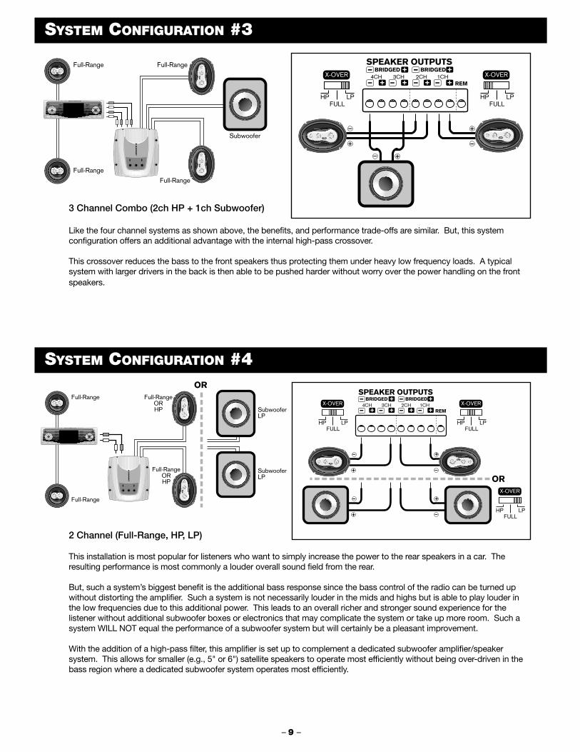
3 Channel Combo (2ch HP + 1ch Subwoofer)
Like the four channel systems as shown above, the benefits, and performance trade-offs are similar. But, this systemconfiguration offers an additional advantage with the internal high-pass crossover.
This crossover reduces the bass to the front speakers thus protecting them under heavy low frequency loads. A typicalsystem with larger drivers in the back is then able to be pushed harder without worry over the power handling on the frontspeakers.
SYSTEM CONFIGURATION #3
2 Channel (Full-Range, HP, LP)
This installation is most popular for listeners who want to simply increase the power to the rear speakers in a car. Theresulting performance is most commonly a louder overall sound field from the rear.
But, such a system’s biggest benefit is the additional bass response since the bass control of the radio can be turned upwithout distorting the amplifier. Such a system is not necessarily louder in the mids and highs but is able to play louder inthe low frequencies due to this additional power. This leads to an overall richer and stronger sound experience for thelistener without additional subwoofer boxes or electronics that may complicate the system or take up more room. Such asystem WILL NOT equal the performance of a subwoofer system but will certainly be a pleasant improvement.
With the addition of a high-pass filter, this amplifier is set up to complement a dedicated subwoofer amplifier/speakersystem. This allows for smaller (e.g., 5" or 6") satellite speakers to operate most efficiently without being over-driven in thebass region where a dedicated subwoofer system operates most efficiently.
SYSTEM CONFIGURATION #4
– 9 –
Full-Range
Full-Range
Full-Range
Full-Range
Subwoofer
Full-Range
Full-Range
Full-RangeORHP
OR
SubwooferLP
SubwooferLP
Full-RangeORHP OR

SYMPTOM
No power (power light not on)
Power but no sound (power light is on)
No sound from one channel or entire side
Very low sound level
Power amplifier turns on and off repeatedly(motor-boating sound)
Amplifier turns off during loud or distortedpassages
Amplifier performs fine but gets very hot tothe touch
Amplifier turn-on/turn-off pops or noises
Cracking noises on AM/FM radio but noton tape or cd.
Whining noise, engine running, varies inpitch or loudness with engine speed, ANDvaries with radio volume control setting(this is generally a RADIO installationproblem)
Whining noise, engine running, varies inpitch or loudness with engine speed, BUT,DOES NOT vary with radio volume controlsetting (this is generally an amplifierinstallation problem)
PROBABLE CAUSE OR CORRECTION
■ Check connections to amps +12 volt, ground, and remote lines.■ Use voltmeter to verify voltages are at terminals of amp.■ Check main power connection at battery.■ Check fuse in power line at battery.■ Disconnect all speakers but not power lines - if unit then turns on, a speaker short
or speaker line touching vehicle chassis is likely.
■ Check all input cable lines for connection.■ Disconnect speakers from amp, test speaker lines with digital voltmeter to verify >2
ohms per channel (non-bridged mode).
■ Check radio’s balance and fader control positions - verify they are at center.■ Check speaker connections at amp and speaker.■ Check input leads for connection to amp.
■ Verify radio balance and fader controls are at center positions.■ Check amplifier’s input gain control setting - adjust for higher output levels if
necessary (gain settings closer to 0.3 volts).■ Receiver may have very low output voltage levels - a step up “line driver” may
have to be used.
■ Make sure power connections at batter are tight.■ Verify battery voltage is >11.5 volts DC (12.5-15V engine on) at amplifier with engine off.■ Check all radio and amplifier ground connections.
■ Input stage being over-driven - lower input gain (closer to 4 volt setting).■ Verify battery voltage is >11.5 volts DC at amplifier with engine off.■ Check all radio and amplifier ground connections.■ Verify speaker loads >2 ohms on all channels (non-bridged mode).
■ Input gain control too high - lower accordingly (closer to 4.0 volt setting).■ Verify speaker loads >2 ohms on all channels (non-bridged mode).■ Verify the mounting location allows for free air movement around the amp.
Preferably, the amp should be mounted with fins up and down so rising heat moves quickly away from amp.
■ “turn on race” - disconnect trigger from radio and turn on/off via a wire jumper to power terminal. If noise goes away, the radio is turning on/off too slowly. This is radio problem and can only be corrected with outboard turn-on delay relay system.
■ Radio “thump” - disconnect the RCA input lines to the amp and turn on/off via radio trigger. If noise goes away without RCA lines connected, the radio is sending pops out through RCA lines. This is a radio problem and can only be corrected with outboard turn-on delay relay system.
■ Ensure the problem is “radiated noise” by placing a portable FM radio near the car engine. If noise is picked up, then it is a vehicle problem and not your system.Research to isolate the source and properly shield or bypass.
■ Are spark plugs and wires > 3 years old? These can often radiate substantial noise when old.
■ Verify the engine block has a good ground connection to chassis ground.■ Verify the engine compartment hood is grounded to vehicle chassis via a braided
grounding strap.
■ Verify all power and ground connections are clean at radio.■ Re-route radio power and ground so they are sourced from same connections back
at amplifier (this is called a “common” ground).■ Check all ground connections to ensure clean surfaces that have all paint removed
and also not oxidation buildup over time.■ Verify there is some kind of power filtering choke assembly at back of radio. If not,
install one.
■ Check battery ground connections at chassis are clean and tight, scraped free of oxidation, paint, and grease.
■ Re-route radio power and ground so they are sourced from same connections back at amplifier (this is called a “common” ground).
■ Bypass all equipment between radio and amp (e.g., equalizers) directly connecting radio. If noise goes away, signal processor has problem.
■ Check for signal level “ground loops” - disconnect the outer shield of the RCA cable at one end of the cable (e.g., radio end). If noise goes away, modify cables accordingly. There are voltage differences at the ground connections of the components and these are NOT correctable any other way than such shield cutting or an outboard “ground loop isolator” which is a small transformer.
TROUBLE-SHOOTING GUIDE
– 10 –
Below is a basic trouble-shooting guide to assist in seeking out and correcting a problem that may occur in the installationprocess. Although lengthy, this chart cannot address every single problem possible but mainly the ones most common.

Robert Bosch Corporation warrants new Blaupunkt car audio products it distributes in the United States through authorized Blaupunktdealers, or which are imported as original vehicle equipment by the automobile manufacturer, to be free from defects in material andworkmanship, in accordance with the following:
For twelve (12) months after delivery to you, the original consumer purchaser, we will repair or at our option replace at no charge to youany car audio product which, under normal conditions of use and service, proves to be defective in materials or workmanship.However, this warranty does not cover expenses incurred in the removal or reinstallation of any car audio product, whether or notproven defective, and does not cover products not purchased from an authorized Blaupunkt dealer. This warranty is limited to theoriginal consumer purchaser and is not transferable. Repaired and replacement car audio products shall assume the identity of theoriginal for purpose of this warranty and this warranty shall not be extended with respect to such products.
To obtain performance of this warranty, contact the nearest Blaupunkt authorized repair facility or our nearest office. A dated purchasereceipt or other proof that the product is within the warranty period will be required in order to honor your claim. Carefully pack the unitand ship prepaid to the servicing location. For further information, write to the Robert Bosch Corporation, 2800 South 25th Avenue,Broadview, Illinois, 60153, attention Blaupunkt Customer Service Department or call 1-800-266-2528.
Specifically excluded from this warranty are failures caused by misuse, neglect, abuse, improper operation or installation, dropping ordamaging, unauthorized service or parts, or failure to follow maintenance instructions or perform normal maintenance activities.Normal maintenance activities for car audio products include but are not limited to cleaning and other minor maintenance activities andadjustments that are outlined in the owner's manual or that are normally required for continued proper operation. Also excluded fromthis warranty is the correction of improper installation and the elimination of any external electromagnetic interference. This warrantysets forth your exclusive remedies with respect to the products covered by it. We shall not be liable for any incidental, consequential,special or punitive damages arising from the sale or use of any Blaupunkt car audio products, whether such claim is in contract or tort.No attempt to alter, modify, or amend this warranty shall be effective unless authorized in writing by an officer of Robert BoschCorporation.
THIS WARRANTY IS IN LIEU OF ALL OTHER WARRANTIES OR REPRESENTATIONS, EXPRESS OR IMPLIED, INCLUDING ANYWARRANTY IMPLIED BY LAW, WHETHER FOR MERCHANTABILITY OR FITNESS FOR A PARTICULAR PURPOSE OR OTHERWISEAND SHALL BE EFFECTIVE ONLY FOR THE PERIOD THAT THIS EXPRESS WARRANTY IS EFFECTIVE.
In the event any provision, or any part or portion of this warranty shall be held invalid, void or otherwise unenforceable, such holdingshall not affect the remaining part or portions of that provision or any other provision hereof.
NOTICE TO CALIFORNIA OWNERS: If your Blaupunkt car audio product needs warranty repair service and there is no authorizedservice center reasonably close to you, you can return the defective unit to the dealer from whom you purchased it, or you can return itto any dealer who sells Blaupunkt car audio products. The dealer may, at the dealer's option, replace, repair or refund the purchaseprice for any Blaupunkt car audio products which prove defective under conditions of normal use. If the dealer fails to repair, replace, orpartially refund your money, you may take your Blaupunkt car audio product to any repair shop and they can repair your unit at ourexpense unless the repair cost exceeds the depreciated value of the unit, but you must contact Blaupunkt to receive authorization todo this before your car audio product is repaired.
ROBERT BOSCH CORPORATIONBLAUPUNKT CUSTOMER SERVICE
2800 SOUTH 25TH AVENUEBROADVIEW, IL 60155TEL: 1-800-266-2528
LIMITED WARRANTY INFORMATION (UNITED STATES ONLY)
These amplifiers are designed to install quickly and easily into most vehicles. Should you experience installation problems,we will make all reasonable efforts to help you, the end purchaser or Installation Technician, to competently install thesecomponents. Before calling us please carefully review this owners manual forthe answers to your questions.
Due to the limited print space of this owners manual, we also offer additionalinformation regarding installation and systems on our Internet site. Via astandard Internet connection through a local Internet Service Provider or otherproviders (e.g., America Online), connect to our web site at the followingaddress: www.BlaupunktUSAcom. On this site we offer technical informationon system design, vehicle integration, product fit guides where possible, andextensive information on loudspeaker design and installation. For the moreadventuresome builder, we also offer our “BlauBox” computer program whichassists in designing subwoofer enclosures. This program is FREE to down loadand use. We also “link out” to other sites that provide additional theory andtechnical support for the consumer and the technically interested.
BLAUPUNKT TECHNICAL SUPPORT
– 11 –

Robert Bosch Corporation, Sales GroupMobile Communications Division2800 South 25th Avenue, Broadview, IL 60155www.BlaupunktUSA.com
Copyright 2001 by the Robert Bosch CorporationNo portion of this work may be reproduced in any form without the written consent of the Robert Bosch CorporationTripath logo, name, and patents are protected by Tripath Corp, Santa Clara, CA Printed in China (September, 2001)
ASSEMBLY & MOUNTING