channel allocation in multi-channel wireless mesh...
TRANSCRIPT

Computer Communications 34 (2011) 803–815
Contents lists available at ScienceDirect
Computer Communications
journal homepage: www.elsevier .com/locate /comcom
Review
Channel allocation in multi-channel wireless mesh networks
Yong Ding, Li Xiao ⇑Department of Computer Science and Engineering, Michigan State University, East Lansing, MI 48824 USA
a r t i c l e i n f o a b s t r a c t
Article history:Received 11 October 2009Received in revised form 26 May 2010Accepted 22 October 2010Available online 31 October 2010
Keywords:Wireless mesh networksCapacityInterferenceChannel allocation
0140-3664/$ - see front matter � 2010 Elsevier B.V. Adoi:10.1016/j.comcom.2010.10.011
⇑ Corresponding author. Tel.: +1 517 353 4386.E-mail addresses: [email protected] (Y. Ding)
In this article, we survey the latest progress in multi-channel wireless mesh networks, focusing on wire-less interference models and channel allocation algorithms with the goal of maximizing the network per-formance. We present the studies of different interference models and illustrate how they could affect thedesign of channel assignment. We also summarize channel allocation algorithms with different strategiesin both omni-directional and directional antenna networks. We conclude that both static and dynamicchannel allocation strategies have advantages and disadvantages, and the design of channel allocationalgorithms strongly depends on the interference model and the assumption of network traffic.
� 2010 Elsevier B.V. All rights reserved.
1. Introduction
Wireless mesh networking has recently become a promisingtechnology that enables many useful applications [1], such asbroadband home networking, community networks, last-mileInternet access, etc. Some commercial deployments and universitytest-beds are already focusing their efforts on these differentapplications.
A wireless mesh network (WMN) consists of mesh routers andmesh clients. Mesh routers are usually assumed to be stationaryand are equipped with one or more wireless interfaces each. Somespecial mesh routers, which are called gateways, have interfaces di-rectly connected to the Internet. While mesh routers provide cov-erage for mesh clients in the neighborhood, they also connect witheach other to form a multi-hop wireless backbone network, whichis able to route traffic between mesh routers or between mesh rou-ters and the Internet through gateways. On the other hand, meshclients can be mobile or stationary and are connected to the net-work through the mesh routers.
One major problem facing WMNs is the capacity reduction ofthe backbone network caused by wireless interference. Whentwo nearby wireless links operate on the same frequency band,they cannot transmit data simultaneously. The use of multiplechannels can alleviate this problem, because the links can transmitdata simultaneously as long as they work on different channels.Therefore, many studies have focused on multi-channel multi-radio WMNs, where each mesh router is equipped with multipleinterfaces, which can be configured with different channels.
ll rights reserved.
, [email protected] (L. Xiao).
In a multi-channel multi-radio WMN, channel allocation be-comes a very important issue. Generally speaking, we want to as-sign each radio of each mesh node with an appropriate channel sothat the network performance can be maximized. As channel allo-cation aims at optimizing network performance, it is usually asso-ciated with the upper layer information such as traffic demands,routing, QoS demands and so on, which makes it a very complexproblem. There have been some surveys of channel assignmentschemes in [2,3]. Both of them summarized channel assignmentalgorithms based on the co-channel wireless interference model(the wireless interference on the same channel) in omni-direc-tional antenna networks. Our paper differs from the previous workin three aspects. (1) We identify more key factors that affect thedesign of channel assignment algorithms, including the differentwireless interference models (both co-channel interference andpartially overlapping channel interference) and the different trafficpatterns. (2) We cover channel assignment algorithms in bothomni-directional and directional antenna WMNs. (3) We providea more comprehensive survey of different channel assignmentalgorithms.
In this paper, we first summarize the studies on wireless inter-ference models in Section 2. These models are used to determinewhether two wireless links will interfere with each other and theirlevel of interference. After that, we focus on channel assignmentalgorithms. The categorization of different approaches is illustratedin Fig. 1. As omni-directional antenna and directional antenna havedifferent interference models, channel allocation should be de-signed differently. In Sections 3–5, we summarize the channelassignment algorithms with static, dynamic, and hybrid strategiesin omni-directional antenna WMNs. In Section 6, we introduce thechannel assignment in directional antenna WMNs. Finally, we

Fig. 2. Channel resource in 802.11b/g [4].
804 Y. Ding, L. Xiao / Computer Communications 34 (2011) 803–815
provide conclusions and identify potential research directions inSection 7.
2. Wireless interference
In this section, we first summarize the studies of co-channelwireless interference and the wireless interference on partiallyoverlapping channels for omni-directional antenna. We then intro-duce the co-channel wireless interference for directional antenna.Note that the wireless transmissions on non-overlapping channelsare assumed not to interfere with each other no matter how closethey are.
2.1. Co-channel interference for omni-directional antenna
There are generally two models, the physical model and theprotocol model, used to determine whether a wireless transmis-sion is successful [5]. Consider a wireless network with N nodes,denoted by ni (1 6 i 6 N).
� Protocol model: Assume each node ni has a transmission range ofR and an interference range of R0. The interference range definesthe longest distance from which the transmission of one nodecan affect the simultaneous reception of the other node. Theinterference range is potentially larger than the transmissionrange. In the protocol model, if node ni transmits to node nj,the transmission is successful if the distance between ni andnj is within R and no other nodes within R0 of nj are transmittingat the same time. If nj needs to send ACK packets to ni for reli-able transmission, the protocol model also requires that noother nodes within R0 of ni are transmitting simultaneously. Thisenables transmissions in both directions to be successful.� Physical model: This model uses the signal-to-noise ratio at the
receiving node to determine whether the packets can bereceived successfully. Suppose node ni wants to transmit tonode nj. Let SSij be the signal strength of ni’s transmissionreceived at nj, and NSj be the total noise at nj, which includesthe interference from other ongoing transmissions in the net-work. Thus, the transmission from ni to nj is successful as longas SSij/NSj P SNRthresh, where SNRthresh is the threshold of sig-nal-to-noise ratio.
The physical model is more accurate than the protocol model,because it takes into account the complex attenuation of wirelesssignal in different environments. However, the protocol model issimpler and easier to derive efficient channel assignment algo-rithms. Up to now, most studies based their channel assignmentalgorithms on protocol interference models.
Fig. 1. Categorization of chann
2.2. Partially overlapping channel interference for omni-directionalantenna
It is known that 802.11b/g provides 14 channels, of which onlythe first 11 channels are permitted in the United States. As illus-trated in Fig. 2, Masafumi04, the channel number represents thecenter frequency on which the radio operates (e.g. 2.412 GHz forchannel 1). The center frequencies are separated by 5 MHz, whileeach channel has a spread of about 22 MHz. Any two channels witha separation over 5 (channel number) are called non-overlappingchannels or orthogonal channels, because their signals do not over-lap with each other. Otherwise, they are partially overlapping chan-nels. Thus, the number of orthogonal channels is at most three(channel 1, 6, and 11) in 802.11b/g.
The authors of [7,8] studied the interference between partiallyoverlapping channels, and found that the interference betweentwo wireless links depends on both their physical distance andchannel separation. When the physical distance is fixed, theirinterference decreases with the increasing channel separation(the difference between the channel numbers that the two linksare configured with). When the channel separation is fixed, theirinterference decreases with the increasing physical distance. Undera fixed channel separation, we can define the interference range asthe minimum distance at which the two links do not interfere witheach other. Let Ic denote the interference range when the channelseparation is c. Fig. 3 illustrates the interference ranges for differ-ent channel separations. Note that I0 is the same with R0, the co-channel interference range defined in Section 2.1.
Most previous studies of channel assignment considered non-overlapping channels only and based their algorithms on co-chan-nel interference models. By considering the partially overlappingchannels in addition to non-overlapping channels, we can fully uti-lize the channel resource, and therefore further improve thenetwork capacity.
el assignment algorithms.

Fig. 3. Interference between partially overlapping channels (Ic denotes the inter-ference range when the channel separation is c).
Y. Ding, L. Xiao / Computer Communications 34 (2011) 803–815 805
2.3. Co-channel interference for directional antennae
Some previous studies focus on omni-directional antennae. In[9], the interference model of directional antennae was analyzed.The experiment was performed on a 2-hop 802.11 mesh networkas shown in Fig. 4. Assume only a single channel is used. Nodes Aand B have one radio each, while node N has two radios communi-cating with A and B respectively. Three pairs of simultaneous oper-ations were simulated: (i) Syn-Rx, node N receives from both links;(ii) Syn-Tx, node N transmits along both links; (iii) Mix-Rx-Tx, nodeN is transmitting along one link while receiving along another link.
If omni-directional antennae are used, all the three simulta-neous operations are infeasible. However, with directional anten-nae, the authors found that while Mix-Rx-Tx is inherentlyinfeasible, Syn-Rx and Syn-Tx are actually feasible if some modifica-tions are made on the MAC layer protocol. An implementation wasproposed in [10]. This particular phenomenon implies that direc-tional antennae have better spatial reuse than omni-directionalantennae.
3. Static channel allocation
In static channel allocation, each interface of each mesh routeris assigned a channel permanently. The goal of static channel allo-cation is to maximize the overall network performance. Most workconsidered orthogonal channels only in the channel allocation. Thewireless links on different orthogonal channels can always worksimultaneously without interference, while the protocol model arewidely used to determine whether simultaneous operations arepossible when links work on the same channel.
Interference is a commonly used metric to evaluate the opti-mality of channel assignment algorithms. To model the interfer-ence within the whole network, the conflict graph model has
Fig. 4. Interference of directional antenna [9].
generally been used. Let G(V,E) represent a wireless mesh network,where V denote mesh routers and vivj 2 E (vi,vj 2 V) if the distancebetween vi and vj is within R, the radio transmission range. A con-flict graph F(S,T) of G(V,E) is defined as a graph that has each vertexsi 2 S corresponding to each link ei 2 E. F has an edge sisj 2 T if thedistance between the two corresponding links ei, ej 2 E is withininterference range of each other (usually 2R). The distance betweenany two links is defined as the minimum distance between anynode of one link and any node of the other link. An example is illus-trated in Fig. 5. In the conflict graph, if there is an edge betweentwo vertices, the two corresponding links cannot be active simulta-neously in the network if they work on the same channel.
The process of channel assignment can be regarded as assigningdifferent colors to vertices of the conflict graph, where each colorrepresents an orthogonal channel. Thus, each monochromatic edgein the conflict graph indicates a pair of interfering links (links thatcannot be active simultaneously). The number of monochromaticedges reflect the number of interfering link pairs, which can beused to evaluate the network interference caused by the channelassignment scheme.
There are two challenges facing static channel assignment. Onechallenge is that we want to minimize the network interference onone hand and do not want to excessively degrade the network con-nectivity on the other hand. However, these two goals are usuallycontradictory, which can be seen from the following two simplechannel assignment algorithms.
� Identical channel assignment algorithm [11] assigns the sameset of channels to each node. For example, we configure theith interface of each node with channel i. Fig. 6(a) illustratesan example where each node has two interfaces. The benefitof this approach is that the connectivity of the network is notdegraded by using different channels. However, the channelassignment has high interference, because each wireless linkis interfering with three links on the same channel.
Fig. 5. An example of conflict graph.
Fig. 6. Tradeoff between interference and connectivity.

806 Y. Ding, L. Xiao / Computer Communications 34 (2011) 803–815
� We can also assign each interface with a least-used channel inthe neighborhood [12]. An example is shown in Fig. 6(b).Although the channel assignment has eliminated the interfer-ence, the network connectivity has been disrupted.
The other challenge is that channel assignment and routing areinter-dependent. If the channel assignment is given, the networktopology can be determined. There exists a wireless link betweentwo nodes if they are within radio transmission range of each otherand have interfaces operating on the same channel. In addition, thebandwidth of each wireless link can also be determined by consid-ering the interfering links in the neighborhood. As a result, the net-work topology and bandwidth of each link can affect the routing ofthe traffic demand. On the other hand, if the routing of traffic de-mands is determined, the network topology and the bandwidthrequirement of each link are also determined, which affects thechannel assignment. Therefore, many studies considered channelassignment and routing together.
The third challenge is how to fully utilize the channel resource.As introduced in Section 2.2, both non-overlapping and partiallyoverlapping channels can be used in channel assignment. Moststudies only utilized non-overlapping channels to mitigate wire-less interference. As the number of non-overlapping channels isusually limited, the use of partially overlapping channels has theprospect further decrease the network interference.
In this section, we first introduce the channel assignment algo-rithms that minimize the interference without considering the ac-tual traffic demand in the network [13] (Section 3.1). To makechannel allocation aware of traffic demand, there are two ap-proaches: (i) Assume the exact traffic profile is known ahead. Thequestion then becomes finding a feasible channel assignment to-gether with a routing scheme so that the traffic profile can be sat-isfied [14] (Section 3.2) or be satisfied as much as possible [15](Section 3.3). (ii) Assume traffic is dynamic but has statistical pat-terns, and find channel assignment schemes that can best satisfythe particular traffic pattern [16] (Section 3.4). Besides, we alsointroduce channel assignment algorithms that utilize partiallyoverlapping channels to further increase the network capacity[28] (Section 3.5). The algorithms in [13,28] can be categorizedas load-unaware static channel assignment, while the algorithmsin [14–16] are categorized as load-aware static channel assign-ment (See Fig. 1). The algorithms introduced in this section arecentralized algorithms. The common notations used by differentalgorithms have been listed in Table 1.
3.1. Minimize interference while keeping connectivity
In [13], the authors formalized the channel assignment as a con-strained optimization problem. Given the mesh network G(V,E),the problem is to find a channel assignment scheme {A(u) ju 2 V},with the goal of minimizing the overall network interference (orthe number of monochromatic edges in the conflict graph F(S,T)),
Table 1Notations.
G(V,E) The network topologyF(S,T) The conflict graph of G(V,E)R The maximum radio transmission rangeK The number of available orthogonal channelsI(u) The number of interfaces of mesh router uA(u) The set of channels assigned to mesh router u; must
satisfy jA(u)j 6 I(u){A(u)ju 2 V} The channel assignment schemel(u,v) The traffic demand from mesh router u to v{l(ui,vi)ji = 1,2, . . . ,m} The traffic profile, where m is the number of flows
while keeping the original network connectivity, that is,A(u) \ A(v) – £ for uv 2 E.
The problem is NP hard, and there have been two heuristic algo-rithms proposed in [13].
� Tabu-based Algorithm: This algorithm consists of two phases. Inthe first phase, a Tabu-search technique is used to find a goodsolution to the problem without worrying about the interfaceconstraint, that is, jA(u)j 6 I(u). More specifically, the searchstarts from a random solution and creates a better solution ateach step in an attempt to reach a good solution in the end. Inthe second phase, the violations of interface constraint areresolved by a repeated color merging procedure. For each meshnode that has been assigned more colors than its number ofinterfaces, two of its colors are merged into one color. This colorchange may propagate to neighboring nodes.� Greedy Algorithm: This algorithm takes another approach by
considering the interface constraint throughout the process. Ini-tially, each vertex of F(S,T) is colored with the same color. Start-ing from this bad solution, the algorithm goes through anumber of iterations, in each of which it tries to find a bettersolution without violating the interface constraint. In each iter-ation, it checks all the valid solutions that are obtained bychanging the color of only one vertex, and selects the one thatleads to the largest decrease in network interference. The algo-rithm terminates when no better solutions can be found.
These algorithms keep the network connectivity while trying toreduce the network interference by using the channel diversity.However, the channel allocation is unaware of the actual networktraffic demand.
3.2. Centralized load-aware channel assignment
The channel assignment and routing of traffic demands havebeen jointly considered in [14]. Given the mesh network G(V,E)and the traffic profile {l(ui,vi)j i = 1,2, . . . ,m}, the problem is to findboth a channel assignment scheme {A(u)ju 2 V} and the routing foreach flow, such that the traffic demand specified by the traffic pro-file can be satisfied.
The basic idea of the algorithm is illustrated in Fig. 7. It startswith an initial estimation of the traffic load on each link. This isachieved by simulating routing algorithms for the traffic profileon the network topology without worrying about the link capacity(or assume each link has infinitive capacity). Given each link’s traf-fic load under the routing scheme, each interface is assigned achannel such that the link load can be satisfied as much as possiblein the resulting network. If the traffic load can be completely
Fig. 7. Centralized load aware channel assignment.

Y. Ding, L. Xiao / Computer Communications 34 (2011) 803–815 807
satisfied on all links, in other words, the capacity of each link underthe channel assignment scheme is no less than the actual link load,then the channel assignment scheme together with the routingscheme is the final solution. Otherwise, the link capacities underthe channel assignment scheme are fed back to the routing step,and routing decisions are re-made under the link capacity con-straint. This process iterates until a solution is found.
Given the traffic load on each link, a greedy algorithm is used toassign channels with the goal of satisfying the bandwidth demandin a best-effort fashion. In the algorithm, the links are visited in thedecreasing order of traffic load. When a link is traversed, it is as-signed a channel, which entails the least degree of interferencebased on the current channel assignment. The degree of interfer-ence is evaluated by the aggregate load on links within the inter-ference range that are assigned the same channel.
3.3. Constant factor optimal algorithm - RCL
In [15], the authors considered both maximizing the networkthroughput and satisfying the fairness among all the flows. Giventhe mesh network G(V,E), they assumed that each mesh router uhas a known and stable aggregated user traffic load l(u,g), whichflows between u and the gateway g through multi-hop relay. Theauthors tried to maximize k such that at least kl(u,g) amount ofthroughput can be satisfied at u.
Given the mesh network G(V,E) and the channel assignmentscheme {A(u)ju 2 V}, u and v can communicate if uv 2 E and A(u),A(v) share a common channel. It is possible to have multiple simul-taneous link transmissions between u and v if there are multiplecommon channels between A(u) and A(v). In order to satisfy kl(u,g)throughput for each mesh router u, we should compute (i) f(e(i))(1 6 i 6 jKj) for each edge e = (u,v), where f(e(i)) denotes the trafficrate from u to v on channel i. (ii) A feasible channel assignment{A(u)ju 2 V}, such that whenever f(e(i)) > 0, i 2 A(u)
TA(v). (iii) A
feasible schedule S = {e, i,s} that decides whether e will transmiton channel i at time slot s, s = 1,2, . . . ,T (T is the period of sche-dule). The schedule must guarantee that no two links within inter-ference range of each other transmit on the same channel at thesame time slot. In other words, if e1 and e2 are within interferencerange of each other, (e1, i,s) and (e2, i,s) cannot co-exist in a feasibleschedule.
The authors proposed a jointrouting, channel assignment and linkscheduling algorithm (RCL) to approximately solve the optimizationproblem. First, a flow on the flow graph (or a routing scheme) witha not necessarily feasible channel assignment is obtained by solv-ing an LP relaxation of the problem. Then, the flow on the flowgraph is adjusted and a feasible channel assignment is computed.A post processing phase follows, in which the channel assignmentis unchanged while the flow is re-adjusted to ensure that the max-imum interference over all channels is minimized. Finally, an inter-ference free link scheduling is computed. The authors proved thatRCL is a constant approximation algorithm for the formulatedproblem, which is NP hard.
Fig. 8. Example of channel assignment.
3.4. Joint topology control and channel assignment
Instead of assuming known and unchanged traffic profiles, theauthors of [16] assumed that dynamic peer-to-peer traffic is themajor traffic in the network, that is, connection demands have ran-dom sources, destinations, and arrival times. In this case, it is desir-able to keep a k-connected network topology while minimizing thenetwork interference. By maintaining a k-connected network, goodrouting paths could be found for dynamic connections. In addition,link congestions can be better avoided so that the network can sat-isfy more traffic demands.
Given the mesh network G(V,E), the channel assignmentscheme {A(u)ju 2 V} determines the network topology. The result-ing topology is denoted by GA; there is an edge between u and vin GA if uv 2 E and A(u), A(v) share a common channel. The authorsdefined the minimum INterference survivable topology control prob-lem (INSTC), which finds {A(u)ju 2 V} with minimum network inter-ference while guaranteeing that GA is k-connected.
To solve the INSTC problem, a heuristic algorithm has been pro-posed, which runs in polynomial time. Define the potential interfer-ence of a link e as the number of links that are within interferencerange of e. The algorithm first finds a k-connected subgraph ofG(V,E) with minimum maximum link potential interference, withthe hope that the finally computed channel assignment will leadto low interference. It then uses a greedy strategy to allocate chan-nels for links in the k-connected subgraph. The links are visited inthe decreasing order of link potential interference. For each link,the least used channel is selected without breaking the interfaceconstraint.
3.5. Channel assignment using partially overlapping channels
The previous algorithms only consider orthogonal channels inthe channel assignment. More specifically, if 802.11b/g is used,they only use three orthogonal channels (1, 6, and 11) for channelassignment. However, there are still some partially overlappingchannels that have not been used. The interference model betweenpartially overlapping channels has been introduced in Section 2.2.
The authors of [28] have demonstrated that the network capac-ity can be further improved by using both the orthogonal and par-tially overlapping channels in channel assignment. An example isshown in Fig. 8. In the square topology, the distance between eachtwo neighboring nodes is R. In addition, each node has two inter-faces that are used for its two wireless links respectively.Fig. 8(a) illustrates a channel assignment scheme with orthogonalchannels only. It can be proved that there is at least one pair ofinterfering links if only three orthogonal channels are used on thistopology. In contrast, Fig. 8(b) demonstrates a channel assignmentscheme with both orthogonal and partially overlapping channels.In the channel assignment, every two links that share a same nodeare assigned with orthogonal channels (channel separation over 5),so they do not interfere with each other. Every two opposite linksare assigned with channels with separation of 2. As the interfer-ence range for channel separation of 2 is I2 < R, they will not inter-fere with each other either. Therefore, the interference iseliminated completely in this case.
In [28], the authors proposed a weighted conflict graph to mod-el the interference of both orthogonal and partially overlappingchannels in multi-channel multi-radio wireless mesh networks.The weighted conflict graph is an extension to the traditional con-flict graph. It defines a label on each edge in the conflict graph,which indicates the minimum channel separation that the two

808 Y. Ding, L. Xiao / Computer Communications 34 (2011) 803–815
links must have so that they will not interfere with each other.Fig. 9 illustrates the weighted conflict graph of the topology inFig. 5. Based on the interference model, the authors further pro-posed two channel assignment algorithms with both orthogonaland partially overlapping channels.
� Greedy algorithm: In each step, the algorithm selects a link,which has not been assigned channel yet and has the leastexpected level of interference with the other links. Then theselected link is assigned with a channel, which has the leastinterference with those links that have already been assignedchannels.� Genetic algorithm: The algorithm maps each channel assignment
scheme to an individual in genetic algorithms. It starts with aninitial population of N individuals (channel assignmentschemes), and evolves M generations. In each step of evolution,it uses the stochastic selection strategy to find parents, and usesone-point crossover and mutation to generate offsprings in thenext generation. The best individual in the last generation isselected as the solution for channel assignment.
Compared with the greedy algorithm, the genetic algorithm isable to find more optimal results. Simulation results have shownthat the network capacity can be improved by around 50 percentby using the genetic channel assignment algorithm with allchannels.
3.6. Summary
In this section, we have introduced both load-unaware ([13,28])and load-aware ([14–16]) channel assignment algorithms. Load-aware channel assignment algorithms are based on prior knowl-edge of the network traffic and requires that the traffic does notchange in the network. In these algorithms, the channel assign-ment is especially designed to optimize the throughput of theknown traffic, so they usually get more optimal results thanload-unaware channel assignment algorithms. However, if the traf-fic changes, the pre-computed channel assignment becomes inap-propriate, and may be less optimal than the load-unaware channelassignment. On the other hand, while most algorithms ([13–16])utilize only non-overlapping channels, we also introduce a channelassignment algorithm that uses both non-overlapping and partiallyoverlapping channels ([28]). The use of partially overlapping chan-nels can further improve the network capacity.
4. Dynamic channel allocation
Different from static channel allocation, dynamic channel allo-cation allows an interface to switch from one channel to another.There are two challenges facing dynamic channel allocation. (1)Current literature shows that the delay of switching an interfacefrom one channel to another cannot be neglected. For channel
Fig. 9. Weighted conflict graph.
switching within the same frequency band (802.11b/g on2.4 GHz or 802.11a on 5 GHz), the delay is shown to be a few hun-dred microseconds to a few milliseconds in [17,18]. For channelswitching across different frequency bands, the delay is expectedto be much larger [19]. (2) A coordination mechanism is neededamong interfaces. When two interfaces want to communicate witheach other, they must switch to the same channel. Therefore, somesynchronization or control protocols are needed to enable inter-faces to negotiate a common channel and switch to the channelsimultaneously.
With regard to how frequently interfaces switch channels, dy-namic channel allocation can be categorized into long-term andshort-term strategies (See Fig. 1).
4.1. Long-term dynamic channel allocation
In long-term dynamic channel switching strategies such as [20](Section 4.1.1) [31] (Section 4.1.2) [21] (Section 4.1.3) [32] (Section4.1.4) [22] (Section 4.1.5), channel switching is usually network-wide and reacts to traffic changes (routing or traffic load) or envi-ronment changes (interference from collocated wireless networks).Among these solutions, [20,31,32] are distributed algorithms,while [21,22] are centralized algorithms.
4.1.1. Distributed routing and channel assignmentIn [20], the authors proposed a distributed dynamic routing and
channel assignment algorithm, which reacts to the traffic change inthe network. The distributed routing and channel assignment algo-rithm consists of two steps: routing tree construction and load-aware channel assignment.
In the first phase, a tree is constructed from each gateway,which acts as the root, and each mesh node associates with onlyone tree. The tree construction starts from the gateway nodes. Ini-tially, each gateway sends out an ADVERTISE message to its neigh-bors, which contains its ‘‘cost’’ of reaching the gateway. Each nodeselects a parent based on the ‘‘cost’’ information. If a node has al-ready joined a tree, it sends out an ADVERTISE message to itsown neighbors for further tree construction. Fig. 10(a) illustratesan example of tree construction. The ‘‘cost’’ metric, which deter-mines the shape of trees, takes three factors into consideration:(i) hop count between a mesh node and the gateway; (ii) gatewaylink capacity, which indicates the residue link capacity to the Inter-net that the gateway can provide; (iii) path capacity, which is theresidue bandwidth of the bottleneck link along the path from themesh node to the gateway.
In the channel assignment step, the interfaces of each meshnode are split into two disjoint sets. As illustrated in Fig. 10(b),the UP-NICs can only be used to communicate with parent nodes,while the DOWN-NICs can only be connected with child nodes.Each node attempts to equally divide its interfaces. This groupingof interfaces makes the channel assignment easier to change with-out causing ripple effects in the network. The channels are as-signed starting from the root of each tree. Each node selects a setof least-used channels in the vicinity for its interfaces. The nodescloser to the gateway have higher priority in selecting channels,because they need to relay more traffic than nodes further fromthe gateway. More specifically, a mesh node can only select thechannels that are not used by any of its interfering neighbors withhigher priority. Thus, links closer to the gateway can have morebandwidth, because they have a wider selection of channels.
4.1.2. Learning based channel assignmentIn [31], the authors proposed a novel learning based approach
for distributed channel assignment. In the process, each mesh nodediscovers its neighbors and the channel usage in its neighborhoodperiodically, and then uses a learning based algorithm to gradually

Fig. 10. Distributed routing/channel assignment [20].
Y. Ding, L. Xiao / Computer Communications 34 (2011) 803–815 809
determine the best channels to assign to its own interfaces. The ap-proach not only achieves efficient channel usage, but also adaptswell to the change of network topology and available channels.
Given K available channels and I interfaces for each mesh node,the number of channel sets that can be assigned to each node is CI
K .Initially, each channel set is associated with equal probability,which means the node has equal chance of choosing any channelset as its channel assignment. After the node initially selects achannel set based on the probability, it then evaluates the qualityof its selected channel assignment. The quality of the channelassignment is measured based on the count of interfering radiosfrom its neighborhood. If the quality of the current channel set isthe best among all possible sets, the probability of the currentchannel set is increased, which is considered as a reward fromthe environment. Otherwise, its probability is decreased, whilethe probability of the remaining sets are increased, which is con-sidered as a punishment. In this way, the channel set of each nodechanges progressively and eventually moves towards a channel setthat is sufficiently diverse from channel sets used by other nodes inthe neighborhood.
4.1.3. Distance-1 constrained channel assignmentUnlike the previous approaches, where the channel assignment
of each interface is determined locally, [21] takes a centralizedstrategy. In this architecture, the gateway of the wireless mesh net-work acts as a centralization point to collect topology knowledge ofthe whole network and compute channel assignment. Then the as-signed channels are distributed to each node. Compared to distrib-uted channel assignment, this approach ensures more optimalchannel allocation in a multi-hop topology at the cost of increasedoverhead of control protocol.
In [21], the authors assumed that each mesh router has only oneinterface, and the routes of all flows have been calculated by sep-arate routing protocols. They proposed a centralize channel assign-ment algorithm to compute the channels of all active links (linksused in routing the flows) in the network. As each node has onlya single half-duplex interface, any two links sharing a mutual nodecannot be active simultaneously. Thus, it has no harm to assignthem with the same channel, because the underlying MAC protocolwill allow only one of them to transmit data at any time. Therefore,the channel assignment only needs to consider distance-1 links,that is, any two links that are within interference range of eachother and do not share a mutual node. A heuristic distance-1 con-strained channel assignment algorithm (D1C � CA) has been pro-posed to minimize the interference between distance-1 links. Theactive links are ordered by their distances to the gateways. Linkscloser to gateways have higher priority in channel assignment be-cause they are more likely to become congested. Finally, each meshnode is notified of the channels for its own links, and a separate
MAC protocol is used to schedule the data transmission of each linkbased on its channel assignment.
4.1.4. Sequence based channel assignmentA distributed channel assignment and routing algorithm has
been proposed in [32]. The algorithm uses channel sequences pre-determined by gateways to eliminate intra-path interference ofeach flow and reduce inter-path interference between differentflows. The proposed channel assignment algorithm is practical,and can be easily implemented with routing in a distributedfashion.
In this approach, each gateway associates a channel sequencewith each of its radios, e.g., c1,c2, . . . ,cn. The sequence must satisfythat any adjacent items cannot be the same channel. If a non-gate-way node u has a path of length l to the gateway, the algorithm willassign channels c1, . . .cl to the links in order staring from the gate-way to u. More specifically, the radio of the gateway is assignedwith channel c1; the intermediate node at ith hop from the gate-way is assigned with channels ci, ci+1 for its two radios, and a radioof u is assigned with channel cl. In this way, the intra-path interfer-ence can be eliminated. In order to reduce the inter-path interfer-ence, the authors use a simple heuristic targeted at minimizing theinterference of first hop transmissions at different gateway radios,because the first hop performance is typically the bottleneck withmultiple flows. In other words, the heuristic is to minimize theinterference among the first channel of all channel sequences.When a non-gateway has communication demand, it first discov-ers its best gateway path with good throughput according to somepath metric, and then uses the channel sequence propagated fromthe gateway to assign channels for the path.
4.1.5. Interference aware channel assignmentA centralized channel assignment algorithms that is aware of
the interference from collocated wireless networks has been ad-dressed in [22]. The authors proposed to mandate one interfaceof each mesh router to work on a default channel, while allowingother interfaces to be configured with different channels to im-prove capacity. The channel allocation of all interfaces is decidedin a centralized way. As illustrated in Fig. 11, each mesh routermeasures the interference from external co-located wireless net-works periodically and sends this information to a central serverCAS. CAS decides the default channel for the mandate interface ofeach mesh router, which minimizes the interference between themesh network and the external co-located wireless networks. Afterthat, CAS runs a breadth first search channel assignment algorithm(BFS-CA) to determine the channels of the other interfaces of eachrouter. BFS-CA performs a breadth first search starting from thegateway node, and gives links closer to the gateway higher priorityin selecting channels because they probably need to carry moretraffic. The computed channel assignment scheme is sent back to

Fig. 11. Interference aware channel assignment.
810 Y. Ding, L. Xiao / Computer Communications 34 (2011) 803–815
each mesh router. To adapt to the changing interference from theco-located wireless networks, CAS periodically re-assigns channelsfor the mandate interface and the other ordinary interfaces. Theperiodicity depends on how frequently the number of interferingdevices occur in the neighborhood and their usage change.
4.2. Short-term dynamic channel allocation
In short-term strategies, channel switching happens frequentlyamong nodes that want to communicate with each other. Thus, theswitching overhead and coordination mechanism are the majorchallenges. There are generally two approaches for short-term dy-namic channel allocation. (i) Devoting a single interface from eachnode for control purpose only [23] (Section 4.2.1). This approachdoes not require synchronization among nodes but may not exploitthe resources efficiently. (ii) No separate interface is devoted forcontrol so that resources can be utilized more efficiently [24] (Sec-tion 4.2.2) [25] (Section 4.2.3), but this approach requires synchro-nization among nodes. All the algorithms introduced in thefollowing are distributed algorithms.
4.2.1. On-demand dynamic channel assignmentAn on-demand dynamic channel assignment mechanism (DCA) has
been proposed in [23]. It assumed that each node has two inter-faces, and there are K orthogonal channels, among which one chan-nel is used as control channel and the rest K � 1 channels are usedas data channels. In DCA, one interface of each node (control inter-face) operates on the control channel permanently, while the otherinterface (data interface) can switch to different data channelsdynamically. The architecture is illustrated in Fig. 12. DCA followsan on-demand style in channel allocation. Only when a pair ofnodes have data to transmit will they use the control channel tonegotiate a data channel for the data interface. In Fig. 12 for exam-ple, node A wanted to transmit to B, so they both switched theirdata interface to data channel 2. Node C and D did not have trans-mission demands, so they did not establish any common data
Fig. 12. On-demand dynamic channel allocation.
channel. When the transmission has been completed, the datachannel is released from the nodes.
The selection of the data channel is based on the local channelusage information. Each node maintains a channel usage list, whichrecords the data channels currently being used by neighboringnodes and when these channels will be released. If node A hassome data to send to B, it first sends a RTS packet to B containingits channel usage list. Node B finds a free channel based on thechannel usage list of both A and itself, and then replies a CTS packetincluding the selected channel to A. On receiving B’s CTS, A sends aRES packet to B for confirmation. The neighbors of A and B overhearfor CTS and RTS packets in the neighborhood, and update theirchannel usage lists accordingly. After the negotiation, A and Bcan switch to the same data channel to transmit data. Differentfrom the previous approaches, DCA is a short-term dynamic chan-nel allocation mechanism, because the channel switching happensvery frequently.
4.2.2. Multi-channel MAC protocolIn [24], the authors proposed a TDMA-style Multi-channel MAC
protocol (MMAC). They assumed that each node is equipped withonly one interface, and there are K orthogonal channels available.In addition, nodes are synchronized in the network, which can beachieved by either out-of-band solutions (such as GPS) or in-bandsolutions (such as IEEE 802.11 timing synchronization function).
The basic idea of MMAC is to divide the time into fixed-lengthintervals, each of which is further divided into control intervaland data interval. In the control interval, all nodes switch to a de-fault channel to negotiate channels to be used in the data interval.In the data interval, nodes switch to the negotiated channels totransmit data. An illustration of MMAC is shown in Fig. 13. The timeis divided into intervals by periodically transmitted beacons. In thecontrol interval (or ATIM Window), if node S has some data des-tined for D, S first sends an ATIM packet to D for channel negotia-tion. Upon receiving the packet, D replies an ATIM-ACK packet toS including the selected channel for data transmission. S then sendsan ATIM-RES packet to D so that the pair of nodes reserve the chan-nel for data interval. To resolve the contention caused by multiplesimultaneous ATIM packets, a random back-off delay has beenused.
In order to select an appropriate channel for data interval, eachnode maintains a preferable channel list (PCL), which records theusage of channels within its neighborhood. During channel negoti-ation in control interval, S embeds its PCL in the ATIM packet sothat D can determine a ‘‘best’’ channel based on the PCL of bothnodes. Each node also overhears the ATIM-ACK and ATIM-RES pack-ets from neighboring nodes to update their own PCL. Two strate-gies can be used to choose the ‘‘best’’ channel: (i) select thechannel that has been used by the least number of neighbors; (ii)select the channel that has the least traffic on it.
In MMAC, only one default channel can be used by all nodes inthe control interval, while all channels including the default chan-nel can be used in the data interval. It has been shown that MMAC(one interface per node) can achieve comparable performance withDCA (two interfaces per node), and thus is more efficient.
4.2.3. Slotted seeded channel hopping protocolA slotted seeded channel hopping (SSCH) protocol has been pro-
posed in [25]. Similar to MMAC, SSCH is applied to a single-inter-face multi-channel network, but it uses a different approach forchannel synchronization.
SSCH divides time into slots (with a fixed duration of 10 mseach), and defines channel schedule as the list of channels thatthe node will switch to in different slots. Assume there are northogonal channels and m slots in each cycle. Each slot i isassigned with a pair (xi,ai), where xi 2 [0,n � 1] is the channel
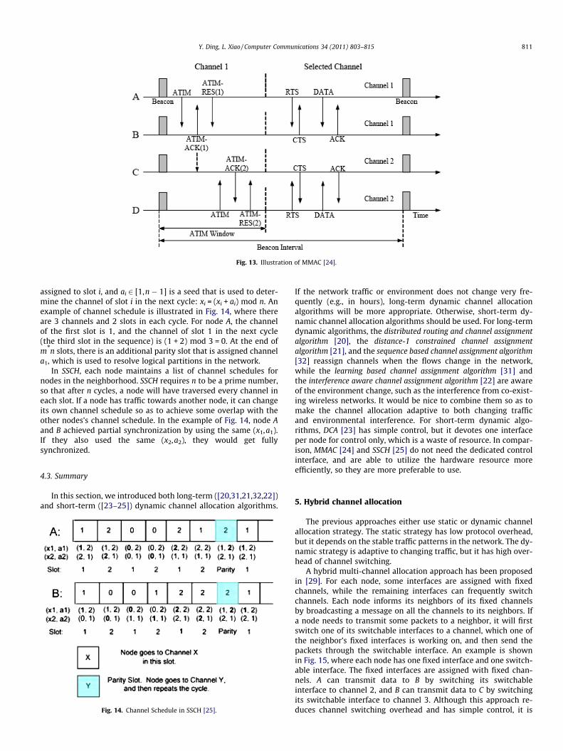
Fig. 13. Illustration of MMAC [24].
Y. Ding, L. Xiao / Computer Communications 34 (2011) 803–815 811
assigned to slot i, and ai 2 [1,n � 1] is a seed that is used to deter-mine the channel of slot i in the next cycle: xi = (xi + ai) mod n. Anexample of channel schedule is illustrated in Fig. 14, where thereare 3 channels and 2 slots in each cycle. For node A, the channelof the first slot is 1, and the channel of slot 1 in the next cycle(the third slot in the sequence) is (1 + 2) mod 3 = 0. At the end ofm*n slots, there is an additional parity slot that is assigned channela1, which is used to resolve logical partitions in the network.
In SSCH, each node maintains a list of channel schedules fornodes in the neighborhood. SSCH requires n to be a prime number,so that after n cycles, a node will have traversed every channel ineach slot. If a node has traffic towards another node, it can changeits own channel schedule so as to achieve some overlap with theother nodes’s channel schedule. In the example of Fig. 14, node Aand B achieved partial synchronization by using the same (x1,a1).If they also used the same (x2,a2), they would get fullysynchronized.
4.3. Summary
In this section, we introduced both long-term ([20,31,21,32,22])and short-term ([23–25]) dynamic channel allocation algorithms.
Fig. 14. Channel Schedule in SSCH [25].
If the network traffic or environment does not change very fre-quently (e.g., in hours), long-term dynamic channel allocationalgorithms will be more appropriate. Otherwise, short-term dy-namic channel allocation algorithms should be used. For long-termdynamic algorithms, the distributed routing and channel assignmentalgorithm [20], the distance-1 constrained channel assignmentalgorithm [21], and the sequence based channel assignment algorithm[32] reassign channels when the flows change in the network,while the learning based channel assignment algorithm [31] andthe interference aware channel assignment algorithm [22] are awareof the environment change, such as the interference from co-exist-ing wireless networks. It would be nice to combine them so as tomake the channel allocation adaptive to both changing trafficand environmental interference. For short-term dynamic algo-rithms, DCA [23] has simple control, but it devotes one interfaceper node for control only, which is a waste of resource. In compar-ison, MMAC [24] and SSCH [25] do not need the dedicated controlinterface, and are able to utilize the hardware resource moreefficiently, so they are more preferable to use.
5. Hybrid channel allocation
The previous approaches either use static or dynamic channelallocation strategy. The static strategy has low protocol overhead,but it depends on the stable traffic patterns in the network. The dy-namic strategy is adaptive to changing traffic, but it has high over-head of channel switching.
A hybrid multi-channel allocation approach has been proposedin [29]. For each node, some interfaces are assigned with fixedchannels, while the remaining interfaces can frequently switchchannels. Each node informs its neighbors of its fixed channelsby broadcasting a message on all the channels to its neighbors. Ifa node needs to transmit some packets to a neighbor, it will firstswitch one of its switchable interfaces to a channel, which one ofthe neighbor’s fixed interfaces is working on, and then send thepackets through the switchable interface. An example is shownin Fig. 15, where each node has one fixed interface and one switch-able interface. The fixed interfaces are assigned with fixed chan-nels. A can transmit data to B by switching its switchableinterface to channel 2, and B can transmit data to C by switchingits switchable interface to channel 3. Although this approach re-duces channel switching overhead and has simple control, it is

Fig. 15. Hybrid multi-channel allocation.
812 Y. Ding, L. Xiao / Computer Communications 34 (2011) 803–815
causing a high delay for data transmission, because the data trans-mission on each hop needs a channel switch.
In [30], the authors proposed a hybrid multi-channel multi-radio wireless mesh network architecture, which combines theadvantages of both static and dynamic channel allocation strate-gies. In this architecture, one interface of each node (dynamicinterface) is able to switch channels frequently, while the remain-ing interfaces (static interface) work on fixed channels. An exampleis illustrated in Fig. 16. Most nodes including the gateway have 3interfaces, and a few boundary nodes {c,g, i, f} have 2 interfaces.The static interfaces of neighboring nodes construct static links(no channel switching) if they work on the same fixed channel.The channel allocation of static interfaces aims at maximizingthe network throughput from end-users to the gateway, whichusually constitutes a major portion of the traffic in the network.As shown in the figure, a tree topology has been constructed bythe channel assignment on static interfaces, which maximizesend-users’ throughput. Dynamic interfaces work in an on-demandfashion. Two dynamic interfaces that are within radio transmissionrange of each other are able to communicate by switching to asame channel when they have data to transmit. Fig. 16 illustratesall the possible dynamic links. The proposed architecture not onlyensures high quality paths by static links, but also improves thenetwork’s connectivity and adaptivity to changing traffic by dy-namic links. Moreover, it also reduces channel switching overhead.
Both hybrid approaches introduced above reduce the channelswitching overhead, compared to dynamic channel allocation ap-proaches, and maintain good adaptivity to changing traffic, com-pared to static channel allocation approaches. In the hybrid multi-channel allocation approach [29], each link is constructed betweena static interface and a dynamic interface, so there is inevitabledelay in data transmission because of channel switching. In com-parison, the hybrid multi-channel multi-radio WMN [30] ensureslow delay paths by static links, which are constructed betweenstatic interfaces. Therefore, it is more preferable to use when thereare both delay sensitive and delay non-sensitive flows.
6. Channel allocation in directional antenna WMNs
In Section 2.3, we have introduced the interference model ofdirectional antennae. Different from omni-directional antenna
Fig. 16. Hybrid WMN Architecture [30].
networks, the Syn-Rx and Syn-Tx operations on the same channelare possible in directional antenna networks. In this section, wefirst introduce a single channel MAC protocol, which efficiently uti-lizes this special property to mitigate interference. After that, weintroduce several channel assignment algorithms in a multi-chan-nel multi-radio directional antenna networks. All of the presentalgorithms for directional antenna networks use static strategiesand are centralized algorithms. Dynamic channel allocation strate-gies have not been used in directional antenna networks because ofthe larger channel switching overhead. When two nodes want tocommunicate, they must not only switch to the same channel,but also tune their directional antennae towards each other.
6.1. 2P MAC protocol using single channel
In [10], the authors proposed a MAC protocol called 2P in a sin-gle-channel directional antenna WMN, which efficiently utilizesthe Syn-Rx and Syn-Tx operations. 2P divides time into fixed-lengthintervals, in each of which a node transmits or receives along all itslinks (Syn-Tx or Syn-Rx). Fig. 17 illustrates the operation of 2P in a4-node network topology, where each node has two directionalantennae. In each interval, either nodes A and C are transmittingalong all links (therefore B and D are receiving) or nodes B and Dare transmitting along all links (therefore A and C are receiving).
In order for 2P to operate properly, the network topology mustbe bipartite, because at any time, if a node is in Syn-Tx, all its neigh-bors must be in Syn-Rx, and vice versa. The authors proposed aheuristic algorithm to construct a bipartite topology of the net-work. It tries to construct a tree, which is inherently bipartite,based on three heuristics: (i) Reducing the length of links used, be-cause a longer link implies higher transmission power in end nodesand therefore more potential interference. (ii) Avoiding small angleseparation between links. Syn-Tx and Syn-Rx become impossibleunder small angle separation because of side-lobe leakage of direc-tional antennae. (iii) Reducing the hop-count. Longer paths usuallysuffer from higher latency and lower throughput because of inter-ference. The algorithm starts from a tree with only the gatewaynode, and adds nodes into the tree level by level until all nodesare connected. The nodes in each level are selected based on theheuristics mentioned above.
6.2. Joint channel allocation and 2P scheduling
One limitation of 2P is its dependency on the bipartite topology.In a general topology that is not bipartite, 2P may not fully utilizethe network capacity. This problem has been investigated in[26,27]. The main idea is to partition the network into multiple dis-joint bipartite subgraphs, each of which is assigned a differentorthogonal channel. Therefore, 2P can be properly scheduled with-in each bipartite subgraph without interfering with 2P schedulingin the other subgraphs. An example of 2P on a general networkwith multiple channels is illustrated in Fig. 18. The network topol-ogy is divided into two bipartite subgraphs, operating on channels1 and 6 respectively. The 2P schedulings in the two sub-networksdo not interfere with each other.
Fig. 17. Illustration of 2P MAC protocol [10].

Y. Ding, L. Xiao / Computer Communications 34 (2011) 803–815 813
In [26], the authors defined a channel subgraph as a maximallyconnected subgraph where all edges are assigned the same chan-nel. Therefore, the problem becomes finding a channel allocationon the original network such that all channel subgraphs are bipar-tite. Given 3 orthogonal channels in 802.11b/g, the authors pro-posed a polynomial channel assignment algorithm for a networkwhose maximum degree is no greater than 5. The basic idea ofthe algorithm is as follows: (i) Find a 6-edge-coloring of the origi-nal network using Vizing’s algorithm. (ii) Merge the colors in pairs,which results in a 3-edge-coloring. As it is unlikely that a node willhave a degree over 5 (require 5 interfaces in other words) in a realdirectional antenna mesh network deployment, the algorithm isapplicable for most networks.
Given K orthogonal channels, the authors of [27] proposed analgorithm to partition the network into K bipartite subgraphs suchthat each subgraph operates on a different orthogonal channel.Given that any cut of a graph is a bipartite graph, the algorithmobtains K bipartite subgraphs by iteratively applying a cut algo-rithm K times on the remaining graph. In each step, the algorithmfinds a cut such that for each node v, the degree of v in the cut isgreater than or equal to its degree in the remaining graph. Theauthors proved that if the maximum degree of the original graphis no greater than 2K � 1, the algorithm can find no greater thanK subgraphs that cover the original graph.
6.3. Channel allocation aware of traffic load
Another limitation of 2P is that it imposes an additional con-straint on each link. Consider the 2P scheduling on a single-channelbipartite subgraph (V1,V2). All links from V1 to V2 have an identicalfraction of active time, and so do links from V2 to V1. For each link,let the fractions of active time in each direction under 2P schedul-ing be its allocated fraction (AF), and the fractions of time it shouldbe active in each direction under given traffic load be its desiredfraction (DF). The problem of minimizing the mismatch betweenAF and DF during channel allocation and 2P scheduling has alsobeen discussed in [26,27].
The authors of [26] considered some additional heuristics in thechannel assignment algorithm. When using Vizing’s algorithm tocolor the original graph, the edges that are ‘‘more difficult’’ to colorare assigned colors first. The difficulty of coloring is evaluated bythe difference between the DF of the edge and its neighboringedges. In addition, when the selected edge is being colored, the col-or that would add the minimum mismatch cost to the graph ischosen.
In [27], some additional steps have been added to the originalalgorithm to minimize the mismatch. After K bipartite subgraphshave been found, each subgraph is assigned a fraction (AF) thatminimizes the total mismatch within the subgraph. Then, q linkswith the highest mismatch among all the subgraphs are selected.There are Kq possible assignments of these links to the K bipartite
Fig. 18. 2P Scheduling under multiple channels.
subgraphs. Among them, only the assignment where each sub-graph remains bipartite is considered. Thus, the valid assignmentwith the lowest total mismatch is chosen to update the bipartitesubgraphs. This process is repeated until the reduction in mis-match is below a predefined constant.
6.4. Summary
In this section, we have summarized two studies, each of whichproposed both load-unaware and load-aware channel assignmentalgorithms. The algorithms are to be used with 2P MAC protocol.For load-unaware channel assignment, both studies proposed algo-rithms, which are optimal under certain constraints. The coloring-based channel assignment algorithm, [26] uses three non-overlap-ping channels in 802.11b/g, and requires that the maximum degreeof the topology is no greater than 5. The partition-based channelassignment algorithm [27] assumes there are K non-overlappingchannels, and requires that the maximum degree of the topologyis no greater than 2K � 1. The load-aware channel assignmentproblem becomes more complex, so both studies proposed modi-fied heuristic channel assignment algorithms based on their origi-nal load-unaware algorithms. In comparison, the partition-basedchannel assignment algorithm is more flexible, because it can beapplied to any number of non-overlapping channels.
7. Conclusion and future work
The channel assignment algorithms are designed differently inomni-directional and directional antenna WMNs because of theirdifferent interference models. Static and dynamic strategies havebeen designed for channel allocation. Static strategies do not re-quire interfaces to switch channels, and thus have lower overhead.However, they depend on the stable network traffic patterns. Onthe other hand, although dynamic strategies have higher channelswitching overhead, they are more appropriate when the networktraffic changes frequently. In static strategies, the cross-layer de-sign between the MAC layer and routing layer is usually consid-ered, while in dynamic strategies, a critical issue is how tocoordinate the channel negotiation and channel switching. Besides,hybrid channel allocation strategy has the prospect to combine theadvantages of both approaches. It is interesting to note that therehave not been any dynamic channel assignment algorithms de-signed for directional antenna WMNs yet because of the large over-head of tuning the direction of antennae.
A comparison of all the channel allocation algorithms is shownin Table 2. From the table, we can conclude that static channel allo-cation algorithms usually have low channel switching overhead,and dynamic channel allocation algorithms are more adaptive tochanging traffic, while hybrid channel allocation algorithms havethe prospect of combining the advantages of both approaches.The channel assignment is an NP-hard problem, so most algo-rithms take the heuristic approach. Most static channel allocationalgorithms are centralized, while most dynamic channel allocationalgorithms are in distributed fashion.
One challenge for future research is the design of channel allo-cation algorithms under more accurate interference models. Mostprevious work based their algorithms on the protocol model,which does not model the interference accurately. As a result, therewill be some difference in the expected performance when thechannel allocation algorithms are deployed in real environments.Therefore, it is necessary to design channel allocation algorithmsbased on more realistic interference models, such as the physicalmodel.
Another challenge is that the channel resource has not beenfully utilized yet. Most previous studies have only considered
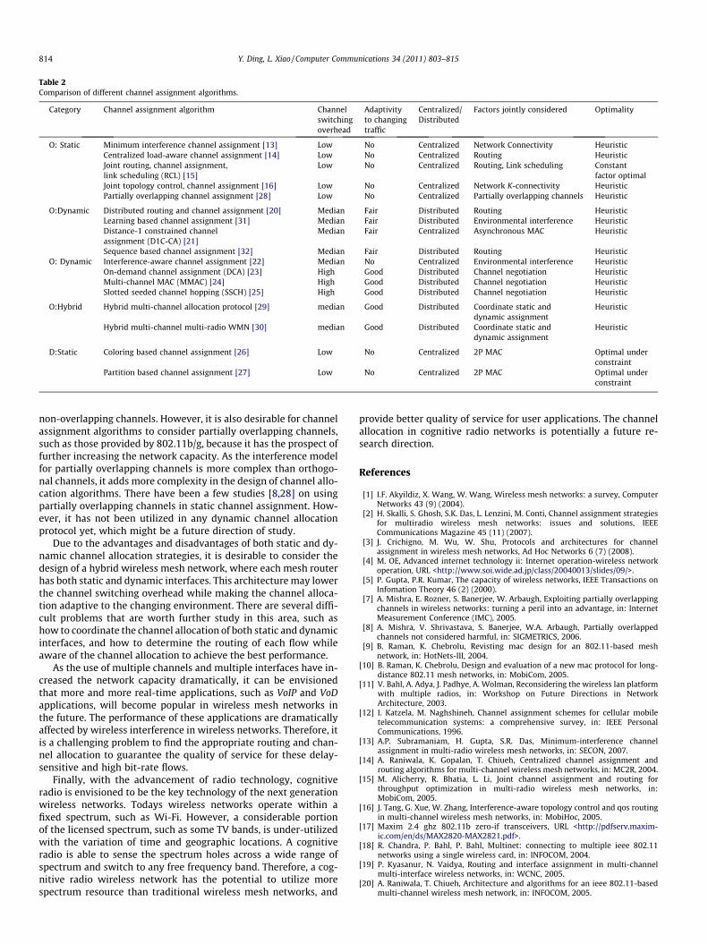
Table 2Comparison of different channel assignment algorithms.
Category Channel assignment algorithm Channelswitchingoverhead
Adaptivityto changingtraffic
Centralized/Distributed
Factors jointly considered Optimality
O: Static Minimum interference channel assignment [13] Low No Centralized Network Connectivity HeuristicCentralized load-aware channel assignment [14] Low No Centralized Routing HeuristicJoint routing, channel assignment,link scheduling (RCL) [15]
Low No Centralized Routing, Link scheduling Constantfactor optimal
Joint topology control, channel assignment [16] Low No Centralized Network K-connectivity HeuristicPartially overlapping channel assignment [28] Low No Centralized Partially overlapping channels Heuristic
O:Dynamic Distributed routing and channel assignment [20] Median Fair Distributed Routing HeuristicLearning based channel assignment [31] Median Fair Distributed Environmental interference HeuristicDistance-1 constrained channelassignment (D1C-CA) [21]
Median Fair Centralized Asynchronous MAC Heuristic
Sequence based channel assignment [32] Median Fair Distributed Routing HeuristicO: Dynamic Interference-aware channel assignment [22] Median No Centralized Environmental interference Heuristic
On-demand channel assignment (DCA) [23] High Good Distributed Channel negotiation HeuristicMulti-channel MAC (MMAC) [24] High Good Distributed Channel negotiation HeuristicSlotted seeded channel hopping (SSCH) [25] High Good Distributed Channel negotiation Heuristic
O:Hybrid Hybrid multi-channel allocation protocol [29] median Good Distributed Coordinate static anddynamic assignment
Heuristic
Hybrid multi-channel multi-radio WMN [30] median Good Distributed Coordinate static anddynamic assignment
Heuristic
D:Static Coloring based channel assignment [26] Low No Centralized 2P MAC Optimal underconstraint
Partition based channel assignment [27] Low No Centralized 2P MAC Optimal underconstraint
814 Y. Ding, L. Xiao / Computer Communications 34 (2011) 803–815
non-overlapping channels. However, it is also desirable for channelassignment algorithms to consider partially overlapping channels,such as those provided by 802.11b/g, because it has the prospect offurther increasing the network capacity. As the interference modelfor partially overlapping channels is more complex than orthogo-nal channels, it adds more complexity in the design of channel allo-cation algorithms. There have been a few studies [8,28] on usingpartially overlapping channels in static channel assignment. How-ever, it has not been utilized in any dynamic channel allocationprotocol yet, which might be a future direction of study.
Due to the advantages and disadvantages of both static and dy-namic channel allocation strategies, it is desirable to consider thedesign of a hybrid wireless mesh network, where each mesh routerhas both static and dynamic interfaces. This architecture may lowerthe channel switching overhead while making the channel alloca-tion adaptive to the changing environment. There are several diffi-cult problems that are worth further study in this area, such ashow to coordinate the channel allocation of both static and dynamicinterfaces, and how to determine the routing of each flow whileaware of the channel allocation to achieve the best performance.
As the use of multiple channels and multiple interfaces have in-creased the network capacity dramatically, it can be envisionedthat more and more real-time applications, such as VoIP and VoDapplications, will become popular in wireless mesh networks inthe future. The performance of these applications are dramaticallyaffected by wireless interference in wireless networks. Therefore, itis a challenging problem to find the appropriate routing and chan-nel allocation to guarantee the quality of service for these delay-sensitive and high bit-rate flows.
Finally, with the advancement of radio technology, cognitiveradio is envisioned to be the key technology of the next generationwireless networks. Todays wireless networks operate within afixed spectrum, such as Wi-Fi. However, a considerable portionof the licensed spectrum, such as some TV bands, is under-utilizedwith the variation of time and geographic locations. A cognitiveradio is able to sense the spectrum holes across a wide range ofspectrum and switch to any free frequency band. Therefore, a cog-nitive radio wireless network has the potential to utilize morespectrum resource than traditional wireless mesh networks, and
provide better quality of service for user applications. The channelallocation in cognitive radio networks is potentially a future re-search direction.
References
[1] I.F. Akyildiz, X. Wang, W. Wang, Wireless mesh networks: a survey, ComputerNetworks 43 (9) (2004).
[2] H. Skalli, S. Ghosh, S.K. Das, L. Lenzini, M. Conti, Channel assignment strategiesfor multiradio wireless mesh networks: issues and solutions, IEEECommunications Magazine 45 (11) (2007).
[3] J. Crichigno, M. Wu, W. Shu, Protocols and architectures for channelassignment in wireless mesh networks, Ad Hoc Networks 6 (7) (2008).
[4] M. OE, Advanced internet technology ii: Internet operation-wireless networkoperation, URL <http://www.soi.wide.ad.jp/class/20040013/slides/09/>.
[5] P. Gupta, P.R. Kumar, The capacity of wireless networks, IEEE Transactions onInfomation Theory 46 (2) (2000).
[7] A. Mishra, E. Rozner, S. Banerjee, W. Arbaugh, Exploiting partially overlappingchannels in wireless networks: turning a peril into an advantage, in: InternetMeasurement Conference (IMC), 2005.
[8] A. Mishra, V. Shrivastava, S. Banerjee, W.A. Arbaugh, Partially overlappedchannels not considered harmful, in: SIGMETRICS, 2006.
[9] B. Raman, K. Chebrolu, Revisting mac design for an 802.11-based meshnetwork, in: HotNets-III, 2004.
[10] B. Raman, K. Chebrolu, Design and evaluation of a new mac protocol for long-distance 802.11 mesh networks, in: MobiCom, 2005.
[11] V. Bahl, A. Adya, J. Padhye, A. Wolman, Reconsidering the wireless lan platformwith multiple radios, in: Workshop on Future Directions in NetworkArchitecture, 2003.
[12] I. Katzela, M. Naghshineh, Channel assignment schemes for cellular mobiletelecommunication systems: a comprehensive survey, in: IEEE PersonalCommunications, 1996.
[13] A.P. Subramaniam, H. Gupta, S.R. Das, Minimum-interference channelassignment in multi-radio wireless mesh networks, in: SECON, 2007.
[14] A. Raniwala, K. Gopalan, T. Chiueh, Centralized channel assignment androuting algorithms for multi-channel wireless mesh networks, in: MC2R, 2004.
[15] M. Alicherry, R. Bhatia, L. Li, Joint channel assignment and routing forthroughput optimization in multi-radio wireless mesh networks, in:MobiCom, 2005.
[16] J. Tang, G. Xue, W. Zhang, Interference-aware topology control and qos routingin multi-channel wireless mesh networks, in: MobiHoc, 2005.
[17] Maxim 2.4 ghz 802.11b zero-if transceivers, URL <http://pdfserv.maxim-ic.com/en/ds/MAX2820-MAX2821.pdf>.
[18] R. Chandra, P. Bahl, P. Bahl, Multinet: connecting to multiple ieee 802.11networks using a single wireless card, in: INFOCOM, 2004.
[19] P. Kyasanur, N. Vaidya, Routing and interface assignment in multi-channelmulti-interface wireless networks, in: WCNC, 2005.
[20] A. Raniwala, T. Chiueh, Architecture and algorithms for an ieee 802.11-basedmulti-channel wireless mesh network, in: INFOCOM, 2005.

Y. Ding, L. Xiao / Computer Communications 34 (2011) 803–815 815
[21] E. Aryafar, O. Gurewitz, E.W. Knightly, Distance-1 constrained channelassignment in single radio wireless mesh networks, in: INFOCOM, 2008.
[22] K.N. Ramachandran, E.M. Belding, K.C. Almeroth, M.M. Buddhikot,Interference-aware channel assignment in multi-radio wireless meshnetworks, in: INFOCOM, 2006.
[23] S.-L. Wu, C.-Y. Lin, Y.-C. Tseng, J.-P. Sheu, A new multi-channel mac protocolwith on-demand channel assignment for multi-hop mobile ad hoc networks,in: International Symposium on Parallel Architectures, Algorithms andNetworks (ISPAN), 2000.
[24] J. So, N. Vaidya, Multi-channel mac for ad hoc networks: handling multi-channel hidden terminals using a single transceiver, in: MobiHoc, 2004.
[25] P. Bahl, R. Chandra, J. Dunagan, Ssch: slotted seeded channel hopping forcapacity improvement ieee 802.11 ad-hoc wireless networks, in: MobiCom,2004.
[26] B. Raman, Channel allocation in 802.11-based mesh networks, in: INFOCOM,2006.
[27] P. Dutta, S. Jaiswal, R. Rastogi, Routing and channel asslocation in ruralwireless mesh networks, in: INFOCOM, 2007.
[28] Y. Ding, Y. Huang, G. Zeng, L. Xiao, Channel assignment with partiallyoverlapping channels in wireless mesh networks, in: WICON, 2008.
[29] P. Kyasanur, N. Vaidya, Routing and interface assignment in multi-channelmulti-interface wireless networks, in: WCNC, 2005.
[30] Y. Ding, K. Pongaliur, L. Xiao, Hybrid multi-channel multi-radio wireless meshnetworks, in: IWQoS, 2009.
[31] S. Pediaditaki, P. Arrieta, M. Marina, A learning-based approach for distributedmulti-radio channel allocation in wireless mesh networks, in: ICNP, 2009.
[32] A. Dhananjay, H. Zhang, J. Li, L. Subramanian, Practical distributed channelassignment and routing in dual-radio mesh networks, in: SIGCOMM, 2009.