champlin watershed assessment - shingle creek and west ... · 2-1 february 2014 2.0 methods wenck...
TRANSCRIPT

Champlin Watershed Assessment
Prepared for:
WEST MISSISSIPPI WATERSHED COMMISSION 8700 Edinbrook Crossing
Brooklyn Park, MN
Prepared by:
WENCK ASSOCIATES, INC. 1802 Wooddale Drive
Suite 100 Woodbury, Minnesota 55125-2937
(651) 294-4580
Wenck File #1241-48
February 2014

i T:\1241 West MS WMC\48 Champlin BMP Assessment\Final report\Champlin Watershed Assessment January 2014.docx February 2014
Table of Contents
1.0 INTRODUCTION .................................................................................................................... 1-1
1.1 Background ...................................................................................................................... 1-1 1.2 Overview .......................................................................................................................... 1-2
2.0 METHODS ............................................................................................................................. 2-1
2.1 Site Assessment ............................................................................................................... 2-1 2.2 WinSLAMM Modeling ...................................................................................................... 2-1 2.3 Existing conditions ........................................................................................................... 2-2 2.4 Limitations and Assumptions ........................................................................................... 2-2
3.0 STORMWATER CONTROL MEASURES .................................................................................... 3-1
3.1 Curb Cut Rain garden ....................................................................................................... 3-1 3.2 Tree Trench ...................................................................................................................... 3-2 3.3 Underground Infiltration ................................................................................................. 3-4 3.4 Infiltration Trench ............................................................................................................ 3-5 3.5 Stormwater Pond ............................................................................................................. 3-6 3.6 MINNESOTA Filter ............................................................................................................ 3-7 3.7 Pervious Pavement .......................................................................................................... 3-9
4.0 POTENTIAL SCM LOCATIONS ................................................................................................. 4-1
4.1 Subwatershed 7V (Mississippi Crossing Development) ................................................... 4-1 4.2 Subwatershed 4V ............................................................................................................. 4-4 4.3 Subwatershed 2T ............................................................................................................. 4-7
5.0 CONCLUSION ........................................................................................................................ 5-1
6.0 REFERENCES ......................................................................................................................... 6-1
Table of Contents (Cont.)
ii February 2014
TABLES
Table 4-1: Proposed Stormwater control measures for implementation in the 7V subwatershed. ......... 4-3 Table 4-2: Proposed stormwater control measures for implementation in the 4V subwatershed. ......... 4-6 Table 4-3: Proposed stormwater control measures for implementation in the 2T subwatershed. .......... 4-9 Table 5-1: Annual TSS removal by watershed SCMs .................................................................................. 5-1 Table 5-2: Annual TP removal by watershed SCMs ................................................................................... 5-2 Table 5-3: Annual runoff volume reduction by watershed SCMs .............................................................. 5-2 FIGURES
Figure 1-1: Map identifying the location of the City of Champlin (blue) within the West Mississippi Watershed. ................................................................................................................. 1-1
Figure 1-2: City of Champlin subwatersheds ............................................................................................. 1-3 Figure 2-1: Subwatershed 4V existing stormwater control measures....................................................... 2-3 Figure 2-2: Subwatershed 2T existing stormwater control measures. . .................................................... 2-4 Figure 3-1: A plan view of a curb cut rain garden with dimensions. ......................................................... 3-1 Figure 3-2: Images of various installations of Rain Guardians in curb cut rain gardens ............................ 3-2 Figure 3-3: The surface view of an installed tree trench in a parking lot on the Villanova Campus in
Pennsylvania ................................................................................................................................. 3-2 Figure 3-4: Tree trench design used on the Central Corridor Light Rail Transit Project. ........................... 3-3 Figure 3-5: Tree trench system in the Maplewood Mall parking lot. ........................................................ 3-4 Figure 3-6: A cross-section of a tree trench using the Stockholm Tree Trench Method. .......................... 3-4 Figure 3-7: A typical cross section and layout showing a half pipe underground infiltration system. ...... 3-5 Figure 3-8: An infiltration trench along a roadside. ................................................................................... 3-5 Figure 3-9: Cross section of an infiltration trench beneath the road. ....................................................... 3-6 Figure 3-10: Stormwater pond in the West Mississippi Watershed. ......................................................... 3-6 Figure 3-11: Image of Minnesota filter showing overflow structures and underdrain ............................. 3-7 Figure 3-12: Minnesota filter installed in a treatment train with a stormwater pond. ............................. 3-8 Figure 3-13: Minnesota filtration basin in the Ramsey-Washington Metro Watershed District .............. 3-8 Figure 3-14: Pervious pavement showing infiltration of runoff ................................................................ 3-9 Figure 3-15: Images of pervious pavement in a parking lot (A) and street parking (B). .......................... 3-10 Figure 4-1: Subwatershed 7V.. ................................................................................................................... 4-2 Figure 4-2: Subwatershed 4V. .................................................................................................................... 4-5 Figure 4-3: Subwatershed 2T.. ................................................................................................................... 4-8 APPENDICES
Appendix A: Curb-Cut Rain Garden Addresses

1-1 February 2014
1.0 INTRODUCTION
1.1 BACKGROUND The City of Champlin is a growing urban community on the Mississippi River located approximately 15 miles north of Minneapolis, Minnesota. Champlin is the northern-most city within the West Mississippi Watershed (Figure 1-1), and is a member of the West Mississippi Watershed Management Commission (WMWMC). The WMWMC is comprised of a five‐member board with representatives from each member city.
Figure 1-1: Map identifying the location of the City of Champlin (blue) within the West Mississippi Watershed. (West Mississippi and Shingle Creek Watershed Management Commissions)
Working in collaboration with the Shingle Creek Watershed Management Commission, the WMWMC developed and adopted the Third Generation Watershed Management Plan in April 2013. This plan details the programs and projects the Commission will undertake over the next 10 years. While the watershed plan details major goals and priorities, it is implemented by and depends heavily on the dedication of member cities. Management Plan goals include reducing the quantity of runoff and improving water quality. This is consistent with the City of Champlin goals of improving water quality and reducing runoff volume through effective planning and developing a cost effective capital

1-2 February 2014
improvement program that identifies stormwater control measures (SCMs) that can be utilized for reconstruction projects and redevelopment. This study is a collaboration between the West Mississippi Watershed and the City of Champlin in considering potential stormwater management alternatives in the City. Development in the study areas occurred prior to stormwater regulation by the WMWMC and prior to the Minnesota Pollution Control Agency’s (MPCA) National Pollutant Discharge Elimination System (NPDES) regulations for Municipal Separate Storm Sewer Systems (MS4). The study identifies SCMs that can be implemented to improve water quality, to help meet the WMWMC goals and provide the City with a planning tool to assist in developing capital improvements and meeting MPCA MS4 requirements. The identified SCMs are a menu of options that can be implemented over the next decade as opportunities arise and funding becomes available and could be constructed as stand-alone projects, part of redevelopments, and/or included as part of road or utility reconstruction projects. 1.2 OVERVIEW To assist the City of Champlin in meeting the goals of the Third Generation Watershed Management Plan, staff from the City and Wenck Associates Inc. (Wenck) identified three subwatersheds in the City that would benefit by incorporating SCMs to improve water quality and address watershed and MS4 requirements. The three subwatersheds are labeled in Figure 1-2 as 4V, 7V, and 2T. Subwatersheds 4V and 7V contain the Mississippi Crossing Development Project which will create a green community along the Mississippi River waterfront. 2T is the largest subwatershed in southeast Champlin containing over 900 acres of mostly residential development. Using information provided by the City, Google Earth, GIS, and WinSLAMM, Wenck evaluated locations for SCMs. SCMs reduce runoff volume and improve water quality through a variety of stormwater management techniques. SCM locations were selected based on the watershed or landscape position, impervious area, land use, soil porosity, and seasonal variations. If all identified SCMs were implemented, the practices would reduce the total suspended solids (TSS) load leaving the city by 139,600 pounds ( 69.8 tons) per year (an annual TSS reduction of 78% from those subwatersheds). In addition, these measures would reduce the total phosphorus (TP) load leaving the city by 265 pounds per year (an annual TP reduction of 53% from those subwatersheds). These practices will infiltrate 312 acre-feet per year (an annual runoff reduction of 47% from those subwatersheds). The expected cost of implementing all practices is $5.9 million. Therefore, as stated earlier, it is not expected that all practices will be implemented but should be viewed as a menu of options that can be implemented as opportunities arise and funding becomes available.

1-3 February 2014
Figure 1-2: City of Champlin subwatershed outlined in red: Three subwatersheds of interest are highlighted and labeled 4V, 7V, 2T

2-1 February 2014
2.0 METHODS
Wenck evaluated the three subwatersheds in Champlin by reviewing existing and proposed conditions. The Mississippi Crossing Development Plan, Google Earth, and a site visit were used to provide an initial assessment of the subwatersheds. Using the computer program WinSLAMM, Wenck created a model of each subwatershed to predict existing runoff volumes and water quality pollutant loading. A series of stormwater control measures (SCMs) were added to the models to predict the potential for runoff volume and pollutant loading reductions within the watershed. 2.1 SITE ASSESSMENT Wenck initially evaluated each subwatershed using the proposed development plans provided, GIS, and Google Earth. This evaluation included delineating impervious areas, researching infiltration rates, and identifying storm sewer, catch basins, and other existing stormwater management practices. The information aided in identifying locations for stormwater management improvements. Wenck conducted a site visit in order to further evaluate SCM feasibility. Based on this site visit, the list of potential locations was refined and more detail was added to the initial site assessment. The locations identified were further evaluated by Wenck to determine the appropriate SCMs to be implemented. The SCMs were selected based on the availability of land, storm sewer location, and predicted runoff volume. Wenck delineated the contributing watersheds for each location and used WinSLAMM to predict runoff. The SCMs were sized to manage the first inch of runoff from the contributing watershed. Due to potential space restrictions in residential areas, some practices were sized to manage one half inch of runoff from impervious areas. 2.2 WINSLAMM MODELING The existing land use and the computer model WinSLAMM were used to calculate the existing pollutant loading for each watershed. WinSLAMM is an empirical model that allows the user to calculate TP and TSS loading and runoff volume based on specific land use criteria. Besides differentiating between commercial, industrial, institutional and residential land uses, WinSLAMM loading calculations differ for flat and sloped roofs; for connected and disconnected impervious; and for streets, parking lots, driveways and sidewalks. In comparison with the P8 water quality model, WinSLAMM requires a much larger amount of input data but is a useful tool for a parcel-scale analysis. An existing conditions model was developed for each subwatershed. To create more detail and accuracy, each subwatershed was broken into smaller sections by storm sewer collection areas. These areas allowed the model more detail and accuracy in prediction. Existing SCMs (stormwater ponds) were included in the models to accurately predict existing conditions. Subwatershed 2T, for example, has a large number of existing stormwater ponds that were incorporated into the model. Each WinSLAMM model was run using a ten year precipitation record, and the average of those ten years was used in the modeling.

2-2 February 2014
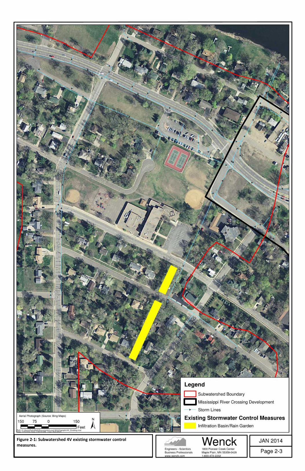
SCMs were added to the existing conditions model based on the potential locations identified during the site assessment and re-executed the WinSLAMM models. These models were used to predict the overall effect of the SCMs on water quantity and quality. 2.3 EXISTING CONDITIONS The City of Champlin has already implemented several SCMs throughout the city to improve stormwater management. These SCMs were included in this study to show ways the City already seeks to improve water quality. Within subwatershed 4V there is an infiltration basin that treats and infiltrates stormwater runoff from the surrounding residences. This infiltration practice currently removes 4,867 pounds (18%) of TSS per year and 4.1 pounds (6.8%) of TP per year. The location of this infiltration basin is shown in Figure 2-1. Champlin has also implemented a rain garden program for its community. The City collaborates with residents to install curb cut rain gardens throughout the community. To date, nine rain gardens have been built within the City. Five of those rain gardens are within subwatershed 2T. These rain gardens range in size from approximately 200 to 800 square feet and remove approximately 80 pounds of TSS per year and 0.25 pounds of TP per year. Subwatershed 2T also has many stormwater ponds that treat runoff to a varying degree. These ponds have relatively shallow permanent pools of water (6-12 inches) and were designed to reduce peak runoff rates. The current stormwater ponds remove approximately 57,000 pounds (31.4%) of TSS per year and 133 pounds (25.4%) of TP per year. The pond locations are shown in Figure 2-2.
2.4 LIMITATIONS AND ASSUMPTIONS Because this is a high level planning document, information about individual sites, topography, utilities, and land use was limited in this assessment, and more detailed information would be necessary on these items to proceed with final design. Soil types were determined based on Web Soil Survey data and standard infiltration rates were used based on those estimates. A detailed soil investigation to determine soil type and groundwater elevations is needed before implementation. The location of major utilities may also affect the location of some identified SCMs.
2-3 February 2014
Figure 2-1: Subwatershed 4V existing stormwater control measures.

2-4 February 2014
Figure 2-2: Subwatershed 2T existing stormwater control measures. Labeled projects correspond to City of Champlin rain garden installations.

3-1 February 2014
3.0 STORMWATER CONTROL MEASURES
Stormwater control measures (SCMs) can be applied in a wide range of urban environments and will vary based on location and the desired result. Filtration, storage, and infiltration are three general approaches to stormwater management. Each approach has a number of design variations and opportunities based on site conditions. A general description of the SCMs selected for this study is presented below. The specific locations identified within Champlin for each practice are shown in subsequent sections. 3.1 CURB CUT RAIN GARDEN Rain gardens (also referred to as bioretention systems) are a familiar practice used to collect and infiltrate rainwater runoff. They are typically shallow depressions with soil engineered to quickly infiltrate water (within 48 hrs.). Effective rain gardens have vegetation that is accustomed to changes in moisture availability and known to remove pollutants. By placing rain gardens along roads and making an opening in the curb, runoff from driveways, houses, and roads enter the rain garden to be treated and infiltrated. This type of rain garden is called a curb cut rain garden. Figure 3-1 is a common layout of a curb cut rain garden. While the size and shape of the rain garden may vary from site to site, the overall layout is similar. When filled, runoff will bypass the rain garden and continue to the next downstream catch basin, pipe, or pond.
Figure 3-1: A plan view of a curb cut rain garden with dimensions. These dimensions will vary based on availability of space and amount of water entering the system. (Image from the Anoka Conservation District and Metropolitan Conservation District)
Rain Guardian

3-2 February 2014
Figure 3-1 also depicts a pre-treatment system developed by the Anoka Conservation District called a Rain Guardian. Pre-treatment for rain gardens is required by the Minnesota Pollution Control Agency (MPCA). The Rain Guardian meets that requirement by filtering out large debris and settling particles from runoff prior to entering the rain garden (Figure 3-2).
Curb cut rain gardens perform best when located on or near storm sewer catch basins. Placing the curb cut upstream of the catch basin allows runoff to first enter and fill the rain garden. Large storm events that exceed the capacity of the rain garden can then overflow into the storm sewer. Image C in Figure 3-2 shows a raised bee-hive outlet installed in the rain garden. In the event of a large storm, the rain garden will capture and infiltrate the “first flush” of runoff and allow excess runoff to overflow to the storm sewer thus reducing pollutant loads and peak runoff flow rates. Maintenance of rain gardens includes inlet and outlet maintenance to prevent clogging, vegetation maintenance, mulch replacement, and sediment and debris removal. Rain garden maintenance needs to be completed seasonally or as needed. 3.2 TREE TRENCH Tree trenches are an SCM that provide underground storage for runoff that is then infiltrated or taken up by tree roots and transpired. They are aesthetically pleasing and particularly useful in highly impervious areas. Sidewalks and boulevards are great locations for tree trenches. A fully functioning tree trench system is shown in Figure 3-3. The Capitol Region Watershed District,
Figure 3-2: Images of various installations of Rain Guardians in curb cut rain gardens. The Rain Guardian provides the pretreatment required by the MPCA for rain gardens. The storm sewer inlet provides an overflow for the rain garden in large storm events. (Images from the Anoka Conservation District and Rain Guardian)
Figure 3-3: The surface view of an installed tree trench in a parking lot on the Villanova Campus in Pennsylvania. (Villanova Sustainable Stormwater Initiative)
A
B
C Raised “bee-hive” outlet

3-3 February 2014
City of St. Paul and Metropolitan Council recently installed tree trenches on the new Central Corridor Light Rail Transit line in St. Paul, MN. These trees are buried in a soil engineered to support the tree root system and collect runoff from the surrounding area. A cross-section of the design is shown in Figure 3-4.
Figure 3-4: Tree trench design used on the Central Corridor Light Rail Transit Project. (Capitol Region Watershed District)
3-4 February 2014
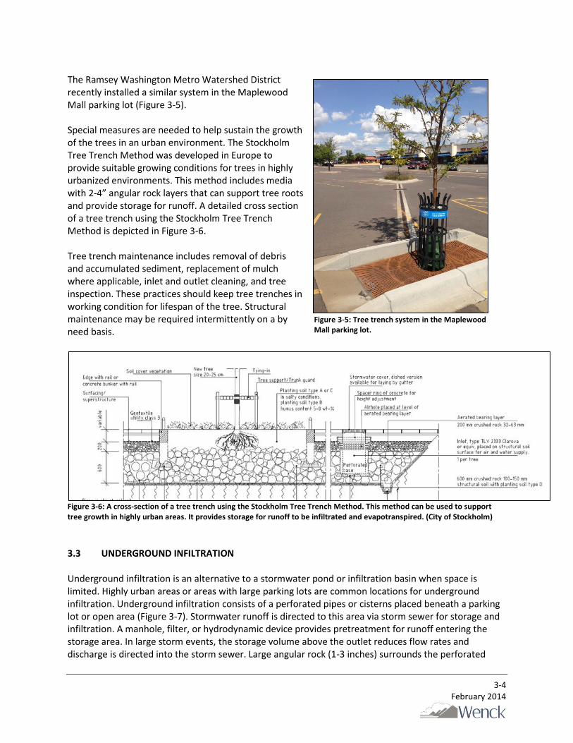
The Ramsey Washington Metro Watershed District recently installed a similar system in the Maplewood Mall parking lot (Figure 3-5). Special measures are needed to help sustain the growth of the trees in an urban environment. The Stockholm Tree Trench Method was developed in Europe to provide suitable growing conditions for trees in highly urbanized environments. This method includes media with 2-4” angular rock layers that can support tree roots and provide storage for runoff. A detailed cross section of a tree trench using the Stockholm Tree Trench Method is depicted in Figure 3-6. Tree trench maintenance includes removal of debris and accumulated sediment, replacement of mulch where applicable, inlet and outlet cleaning, and tree inspection. These practices should keep tree trenches in working condition for lifespan of the tree. Structural maintenance may be required intermittently on a by need basis.
Figure 3-6: A cross-section of a tree trench using the Stockholm Tree Trench Method. This method can be used to support tree growth in highly urban areas. It provides storage for runoff to be infiltrated and evapotranspired. (City of Stockholm)
3.3 UNDERGROUND INFILTRATION Underground infiltration is an alternative to a stormwater pond or infiltration basin when space is limited. Highly urban areas or areas with large parking lots are common locations for underground infiltration. Underground infiltration consists of a perforated pipes or cisterns placed beneath a parking lot or open area (Figure 3-7). Stormwater runoff is directed to this area via storm sewer for storage and infiltration. A manhole, filter, or hydrodynamic device provides pretreatment for runoff entering the storage area. In large storm events, the storage volume above the outlet reduces flow rates and discharge is directed into the storm sewer. Large angular rock (1-3 inches) surrounds the perforated
Figure 3-5: Tree trench system in the Maplewood Mall parking lot.

3-5 February 2014
pipes and provides additional storage capacity and structural stability for soils above. The system is designed to infiltrate within 48 hours per MPCA guidelines.
Figure 3-7: A typical cross section and layout showing a half pipe underground infiltration system. This system may be placed under a parking lot, park, or other area to accommodate storage and infiltration of runoff. (Connecticut Stormwater Manual)
Access limitations require the underground system to be designed properly in order to prevent system failure. Pre-treatment devices are required and usually consist of manhole sumps and/or hydrodynamic devices that remove oil, grease, and floatables. Maintenance activities include pre-treatment device cleanout, inspections, and repair of damaged areas. The life span expected for the underground system is upwards of 25 years. 3.4 INFILTRATION TRENCH Infiltration trenches are long depressions that store and infiltrate runoff. They can be designed to collect runoff from impervious surface (Figure 3-8) or operate as an offline storm sewer. The offline storm sewer system diverts runoff from the storm sewer to the infiltration trench, similar to other infiltration practices. As the infiltration trench reaches capacity, the runoff continues through the storm sewer. The infiltration trench improves water quality, infiltrates runoff, and reduces peak runoff flow rates. Street replacement provides an ideal opportunity for this SCM. Combining street reconstruction and SCM placement is a cost effective solution to reduce runoff. Infiltration trenches can be placed beneath roads where no utilities are present. Runoff is directed to the underground system using the storm sewer, and when the system is saturated, runoff is conveyed through the storm sewer as before (Figure 3-9).
Figure 3-8: An infiltration trench along a roadside. Runoff enters the trench directly and no curb is installed. (Minnesota Stormwater Manual)

3-6 February 2014
When a road is being replaced, the underground infiltration can be added to the project to reduce downstream pollutant loads.
Figure 3-9: Cross section of an infiltration trench beneath the road.
Infiltration trenches require regular maintenance in order to optimize performance. Maintenance includes replacement of soils as needed, inlet and outlet maintenance, pre-treatment device maintenance, vegetation maintenance, repair of eroded areas, and regular inspections. 3.5 STORMWATER POND Stormwater ponds collect runoff from the upstream watershed and release it at a controlled rate. Ponds also act as sedimentation basins that remove suspended solids and large debris to improve water quality. Typically, it is desirable to maintain standing water in stormwater ponds in order to provide treatment (minimum 3 feet, maximum 10 feet). The stormwater pond depicted in Figure 3-10 is an existing pond in the West Mississippi Watershed. These ponds are able to remove an average of 85% of the TSS and 50% of the TP contained in stormwater runoff. Pond maintenance includes regular inspection and periodic removal of accumulated sediment.
Figure 3-10: Stormwater pond in the West Mississippi Watershed. This pond slows water which causes sedimentation and improves water quality.
3-7 February 2014
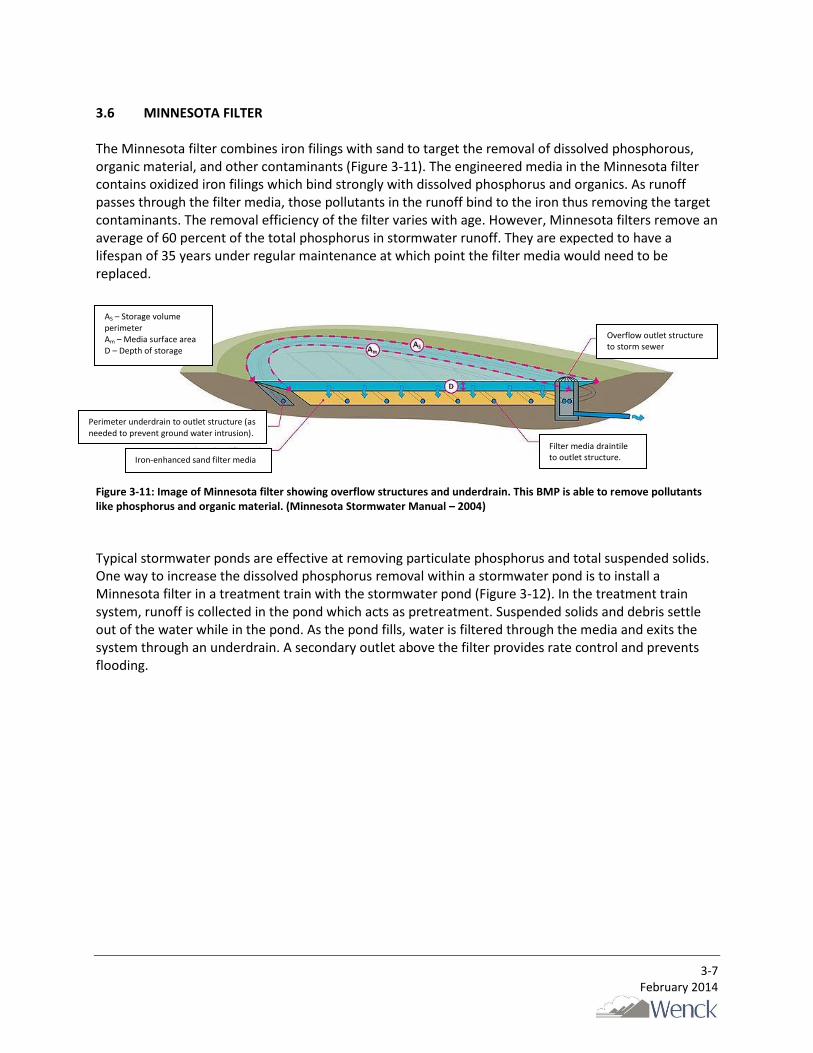
3.6 MINNESOTA FILTER The Minnesota filter combines iron filings with sand to target the removal of dissolved phosphorous, organic material, and other contaminants (Figure 3-11). The engineered media in the Minnesota filter contains oxidized iron filings which bind strongly with dissolved phosphorus and organics. As runoff passes through the filter media, those pollutants in the runoff bind to the iron thus removing the target contaminants. The removal efficiency of the filter varies with age. However, Minnesota filters remove an average of 60 percent of the total phosphorus in stormwater runoff. They are expected to have a lifespan of 35 years under regular maintenance at which point the filter media would need to be replaced.
Figure 3-11: Image of Minnesota filter showing overflow structures and underdrain. This BMP is able to remove pollutants like phosphorus and organic material. (Minnesota Stormwater Manual – 2004)
Typical stormwater ponds are effective at removing particulate phosphorus and total suspended solids. One way to increase the dissolved phosphorus removal within a stormwater pond is to install a Minnesota filter in a treatment train with the stormwater pond (Figure 3-12). In the treatment train system, runoff is collected in the pond which acts as pretreatment. Suspended solids and debris settle out of the water while in the pond. As the pond fills, water is filtered through the media and exits the system through an underdrain. A secondary outlet above the filter provides rate control and prevents flooding.
Perimeter underdrain to outlet structure (as needed to prevent ground water intrusion).
Iron-enhanced sand filter media
Overflow outlet structure to storm sewer
Filter media draintile to outlet structure.
Am AS
D
AS – Storage volume perimeter Am – Media surface area D – Depth of storage

3-8 February 2014
Figure 3-12: Minnesota filter installed in a treatment train with a stormwater pond. The two images show the system before and after a storm event. As the pond fills with water from a storm it begins to enter the iron filter. (University of Minnesota, Andrew Erickson)
Minnesota filters can alternately be implemented as a stand-alone filtration basin. Figure 3-13 is an example of Minnesota filtration basin. The filtration basin design is ideal in locations where infiltration is either not practical or possible due to stormwater “hotspots”, existing contamination or high groundwater. Hotspots are defined as “commercial, industrial, institutional, municipal, or transportation related operations that may produce higher levels of stormwater pollutants, and/or present a higher potential risk for spills, leaks, or illicit discharges (CRWD, 2012).”
Figure 3-13: Minnesota filtration basin in the Ramsey-Washington Metro Watershed District (Ramsey-Washington Metro Watershed District).

3-9 February 2014
3.7 PERVIOUS PAVEMENT Pervious pavement has several different designs that follow the same general structure and result in reduced runoff volumes. Impervious pavement (concrete or asphalt) is replaced with a material that allows water to pass through to the sub-base. The sub-base consists of an angular rock with large void spaces to temporarily store and infiltrate water that passes through the pervious pavement above. This method of pavement construction provides a means of infiltrating runoff from paved surfaces as well as any other contributing surface areas. See Figure 3-14 for an illustration of the pervious pavement and how water flows through it.
Figure 3-14: Pervious pavement showing infiltration of runoff. (USDA and NRCS)
While pervious pavement remains unproven for heavy traffic, trucks, and high speeds, it is well suited to handle light traffic and occasional heavy vehicles. Potential areas for implementation are parking lots, residential roads, driveways, and other similar surfaces (Figure 3-15). To ensure long performance of pervious pavement, it is important to maintain the pavement. Periodic vacuuming is the key maintenance needed for pervious pavement and using little or no salt in the winter is recommended. Studies have shown that de-icing chemicals can be reduced or eliminated because snow-melt and ice infiltrates rather than refreezing. Maintenance of the surrounding landscaped areas will also ensure that the pavement does not become clogged with eroded sediment.

3-10 February 2014
Figure 3-15: Images of pervious pavement in a parking lot (A) and street parking (B).
B A
Pervious Pavement
Standard Pavement
Standard Pavement
Pervious Pavement

4-1 February 2014
4.0 POTENTIAL SCM LOCATIONS
Wenck evaluated three subwatersheds in Champlin to determine ideal locations for stormwater control measures (SCMs). Based on the evaluation, Wenck identified 27 potential SCMs for improving water quality and reducing runoff volume from the urbanized watershed. The combined removal efficiency for all of these practices is 78% or 139,600 pounds per year for TSS; 265 pounds per year or 53% of the expected annual load for TP; and 312 acre-feet of runoff annually which is 47% of the total runoff. In all, the construction cost for all potential SCMs is approximately $5.9 million. It is not expected that all practices will be implemented but should be viewed as a menu of options that can be implemented as opportunities arise and funding becomes available. 4.1 SUBWATERSHED 7V (MISSISSIPPI CROSSING DEVELOPMENT) The City of Champlin’s Mississippi Crossing Master Plan was the basis for development of a stormwater management plan for Subwatershed 7V. Based on the proposed development conditions, eight potential SCMs were identified to reduce peak volume, total suspended solids, and phosphorus from the watershed. Figure 4-1 shows the locations of the potential SCMs. (Each number corresponds to a proposed SCM.) Wenck calculated that the proposed Mississippi Crossing Development without SCMs would export approximately 24,500 pounds of TSS, 47 pounds of TP, and 53 acre-feet of runoff annually. Table 4-1 lists potential SCMs and details regarding size, watershed area, construction cost, maintenance cost, pollutant removal, and property owner. The numbering in Table 4-1 corresponds to the locations in Figure 4-1. The SCMs will remove a total of 22,500 pounds of TSS, 39 pounds of TP, and infiltrate 27 acre-feet of runoff annually. The estimated total cost of all the potential SCMs in this subwatershed is $1.7 million. Construction and maintenance costs are based on Best Management Practices Construction Costs, Maintenance Costs, and Land Requirements (Barr 2011). Wenck calculated each SCM construction and maintenance cost using the average cost per runoff volume treated. Wenck calculated the cost per pound of TP removed for a 20 year lifespan including maintenance over the 20 years.

4-2 February 2014
Figure 4-1: Subwatershed 7V. Numbers correspond to the location of stormwater control measures.

4-3 February 2014
Table 4-1: Planning options of Stormwater Control Measures identified in the 7V subwatershed.
ID BMP Size (sf)
Watershed Area Construction
Cost
Annual Maintenance
Cost
Annual Removal
$/lb TP Removed
Volume Reduction
(ac-ft) Land Owner TSS TP
Acres lb/yr lb/yr
1 Infiltration
Trench 4,000 3.0 $160,000 $3,000 715 1.4 7,900 1.4
Champlin Economic
Development Authority
2 Minnesota Filtration
Basin 5,000 8.0 $65,000 $6,000 1,664 6.9 1,300 0.0
City of Champlin
3 Tree Trench 12,000 10.0 $600,000 $11,000 4,942 7.5 5,500 13.2 City of
Champlin
4 Pervious
Pavement 12,000 3.0 $240,000 $400 661 0.6 20,700 1.1
City of Champlin
5 Infiltration
Basin 4,000 6.5 $52,000 $5,000 1,132 1.4 5,400 2.3
Champlin Economic
Development Authority
6 Tree Trench 5,200 4.0 $260,000 $5,000 1,548 0.8 22,500 7.8 MnDOT right of
way
7 Curb Cut
Rain Garden
600 1.0 $9,000 $400 568 0.9 900 1.3 Residential -
229 and 231 E River Pkwy
8
Stormwater Pond with Minnesota
Filter
30,000 44 $270,000 $2,000 11,234 19.3 800 0.0 City of
Champlin
A potential infiltration trench location (1) was identified in an undeveloped area just west of Highway 169. In the Mississippi Crossing Plan, this area is proposed as a parking lot. Storage space beneath parking lots promotes infiltration with virtually no surface area requirement. The design of this infiltration trench could include a low flow diversion from the storm sewer on Highway 169 which collects runoff from the development on site and a portion of the highway. This infiltration system was sized to store the first inch of runoff from impervious surfaces in the surrounding development (1.5 acres) and 2 acres of Highway 169. A potential Minnesota filtration basin location (2) in the northern section of the Mississippi Crossing Development is sized to accommodate the first inch of runoff from three proposed buildings: the event center, a residential building, and commercial building as well as surrounding driveways and sidewalks. A filtration basin is preferable to an infiltration basin because the site is a potential hotspot, as is the gas station to the south. Based on the WinSLAMM model, this filtration basin would provide an inexpensive and very effective solution for pollution and runoff volume reduction. Similarly, potential infiltration basin (5) provides storage and infiltration for the first inch of runoff from two proposed residential developments. There are two potential locations for tree trenches. Tree trench (3) could be located along both sides of the road through the Mississippi Crossing Development. It would capture runoff from 3 acres of road and 1.5 acres of surrounding impervious surface (buildings, sidewalk, etc.). Pervious pavement (4) could be used for an 8 foot wide section along the edge of the road where parallel parking may be available. The rock storage below the pervious pavement would be connected to the rock in the tree trench system. The pervious pavement and the tree trench would then operate as a treatment train system to infiltrate and evapotranspire stormwater runoff. This ‘green street’ design would serve to sustainably manage stormwater as well as provide an aesthetically pleasing walkway.

4-4 February 2014
The second tree trench location (6) could be along the northern side of Highway 169 in the highway right of way. Runoff from this section of highway within the subwatershed could be diverted to this tree trench where the first inch of runoff could be stored and infiltrated. The existing storm sewer system could be diverted at minimal cost. For the existing houses along the Mississippi (213-327 East River Parkway), a small curb cut rain garden (7) could provide storage and infiltration of runoff. The rain garden could be sized to store the first half inch of runoff from 10 houses. This includes any runoff from the street and residential property that drains to the street. The estimated construction cost includes a Rain Guardian for pretreatment. The final potential SCM is a stormwater pond that would overflow into a Minnesota Filter (8). This treatment train system could store and filter the runoff from nearly half of the subwatershed including the remaining portion of the Mississippi Crossing Development not already being treated. In addition, passing all stormwater from the contributing watershed through this pond and filter would remove a large amount of TSS and TP. The Highway 169 storm sewer system and the southern portion of the 7V subwatershed already drain to this area and could be diverted to direct all runoff to this pond before discharging to the Mississippi River. This is an opportunity for the City to work with MNDOT for long term solutions to water quality along Highway 169. This would benefit both MNDOT and the City in meeting MS4 requirements. 4.2 SUBWATERSHED 4V Subwatershed 4V has one infiltration basin that receives some watershed runoff, but is otherwise drained by a storm sewer that discharges to the Mississippi River. Based on WinSLAMM models, the existing watershed conditions export approximately 30,800 pounds of TSS and 61 pounds of TP annually. This estimate includes the portion of the proposed Mississippi Crossing Development within Subwatershed 4V. Six potential SCMs were identified for Subwatershed 4V. Two of the potential SCMs have the same contributing watershed but will offer better reduction in peak volume, TSS, and TP loads when used together. Figure 4-2 shows the locations of the potential SCMs and Table 4-2 describes each practice with more detail. The estimated total cost of implementing all the potential SCMs in this subwatershed is $1.0 million. The identified SCMs would remove a total of 25,000 pounds of TSS and 51 pounds of TP annually.

4-5 February 2014
Figure 4-2: Subwatershed 4V. Numbers correspond to the location of stormwater control measures.
4-6 February 2014
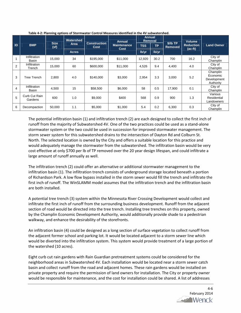
Table 4-2: Planning options of Stormwater Control Measures identified in the 4V subwatershed.
ID BMP Size (sf)
Watershed Area Construction
Cost
Annual Maintenance
Cost
Annual Removal
$/lb TP Removed
Volume Reduction
(ac-ft) Land Owner TSS TP
Acres lb/yr lb/yr
1 Infiltration
Basin 15,000 34 $195,000 $11,000 12,920 30.2 700 16.2
City of Champlin
2 Infiltration
Trench 15,000 60 $600,000 $11,000 4,526 9.4 4,400 4.0
City of Champlin
3 Tree Trench 2,800 4.0 $140,000 $3,000 2,954 3.3 3,000 5.2
Champlin Economic
Development Authority
4 Infiltration
Basin 4,500 15 $58,500 $6,000 58 0.5 17,900 0.1
City of Champlin
5 Curb Cut Rain
Gardens 600 1.0 $9,000 $400 568 0.9 900 1.3
Various Residential Landowners
6 Decompaction 50,000 1.1 $5,000 $1,000 5.4 0.2 6,300 0.3 City of
Champlin
The potential infiltration basin (1) and infiltration trench (2) are each designed to collect the first inch of runoff from the majority of Subwatershed 4V. One of the two practices could be used as a stand-alone stormwater system or the two could be used in succession for improved stormwater management. The storm sewer system for this subwatershed drains to the intersection of Dayton Rd and Colburn St. North. The selected location is owned by the City and offers a suitable location for this practice and would adequately manage the stormwater from the subwatershed. The infiltration basin would be very cost effective at only $700 per lb of TP removed over the 20 year design lifespan, and could infiltrate a large amount of runoff annually as well. The infiltration trench (2) could offer an alternative or additional stormwater management to the infiltration basin (1). The infiltration trench consists of underground storage located beneath a portion of Richardson Park. A low flow bypass installed in the storm sewer would fill the trench and infiltrate the first inch of runoff. The WinSLAMM model assumes that the infiltration trench and the infiltration basin are both installed. A potential tree trench (3) system within the Minnesota River Crossing Development would collect and infiltrate the first inch of runoff from the surrounding business development. Runoff from the adjacent section of road would be directed into the tree trench. Installing tree trenches on this property, owned by the Champlin Economic Development Authority, would additionally provide shade to a pedestrian walkway, and enhance the desirability of the storefronts. An infiltration basin (4) could be designed as a long section of surface vegetation to collect runoff from the adjacent former school and parking lot. It would be located adjacent to a storm sewer line which would be diverted into the infiltration system. This system would provide treatment of a large portion of the watershed (10 acres). Eight curb cut rain gardens with Rain Guardian pretreatment systems could be considered for the neighborhood areas in Subwatershed 4V. Each installation would be located near a storm sewer catch basin and collect runoff from the road and adjacent homes. These rain gardens would be installed on private property and require the permission of land owners for installation. The City or property owner would be responsible for maintenance, and the cost for installation could be shared. A list of addresses

4-7 February 2014
for the proposed rain garden locations is located in the Appendix A. Note that Table 4-2 provides details for one average curb cut rain garden. These details would apply to each of the eight rain gardens proposed. Therefore, in the event that all eight rain gardens are installed, cost and treatment would be multiplied by eight. Decompaction (6) of the outfield of the ballpark would also have a positive influence on stormwater runoff. The loosened soil would better accommodate infiltration which would reduce runoff volume and pollutant load. The decompaction process is generally very inexpensive but does require replanting grass. This practice, however, would need to be repeated on a regular basis, possibly every five years, which causes an increased maintenance expense. It would be beneficial for the City to consider purchase of decompaction equipment so that more properties throughout the City can be improved at reduced cost. Wenck recommends that the infiltration basin (1) and rain gardens (5) be given the highest priority for implementation. These two SCMs offer the most cost effective means of treating and reducing stormwater runoff. The remaining SCMs should be given the priority in order the order 3, 2, and then 6. Practice 4 is an example that could be used in different development projects but does not provide effective treatment here. 4.3 SUBWATERSHED 2T Subwatershed 2T is more than 12 times larger than Subwatersheds 7V and 4V and is mostly residential. The majority of runoff collects in existing stormwater ponds and lakes that have overflows into the storm sewer. This storm sewer system outlets into the Mississippi River. Based on WinSLAMM models, the current watershed conditions export approximately 124,700 pounds of TSS and 390 pounds of TP annually. This estimate takes into account the effect of the existing stormwater ponds within Subwatershed 2T. Wenck identified thirteen SCMs for Subwatershed 2T (Figure 4-3). Note that practices (5) and (7) have multiple locations and are therefore place-markers for the SCMs. Table 4-3 details each practice identified in Figure 4-3. The total cost of implementing the identified SCMs in this subwatershed is $3.2 million. The SCMs would remove a total of 89,100 pounds of TSS and 195 pounds of TP annually.
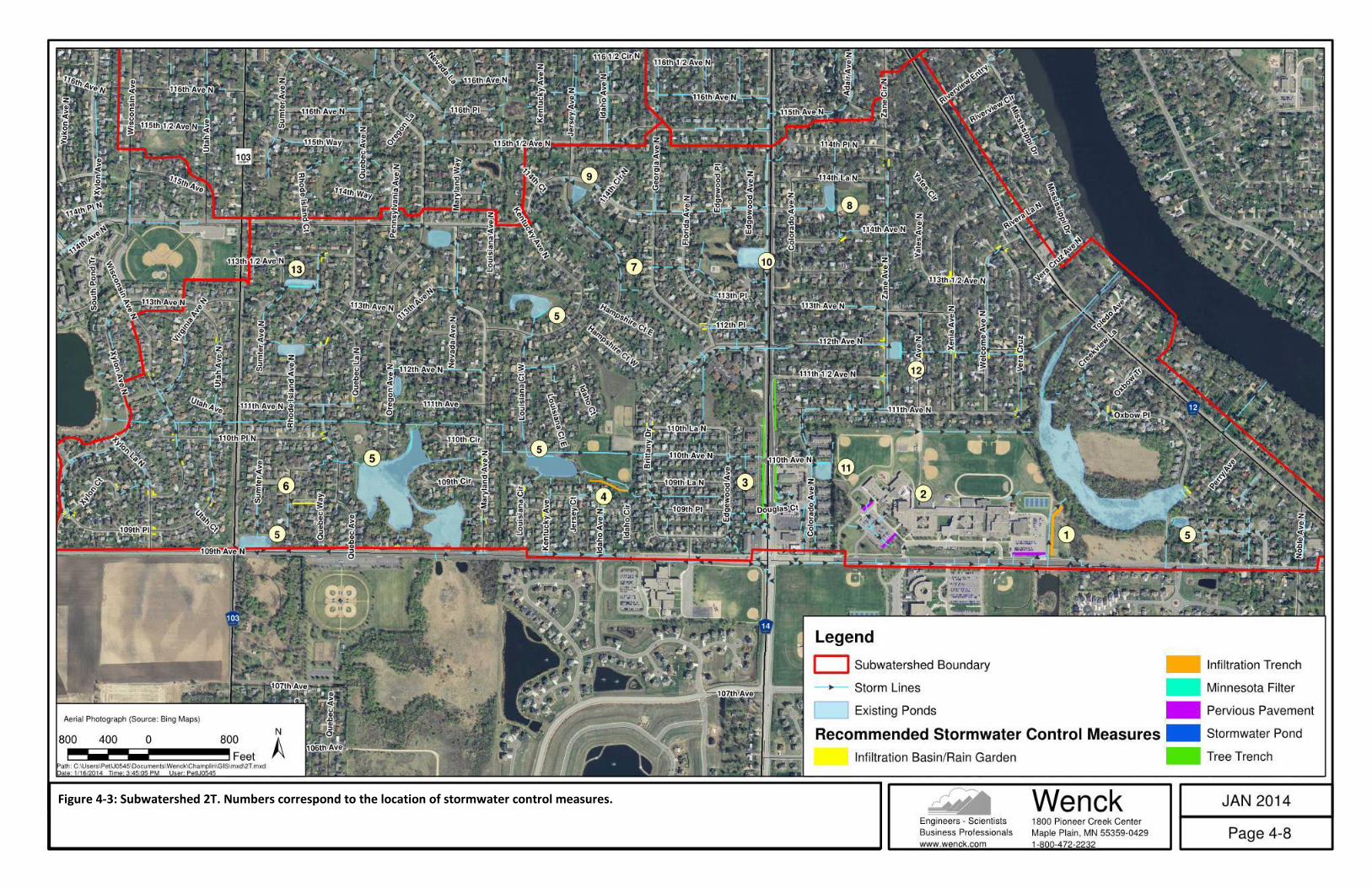
4-8 February 2014
Figure 4-3: Subwatershed 2T. Numbers correspond to the location of stormwater control measures.

4-9 February 2014
Table 4-3: Planning options of Stormwater Control Measures identified in the 2T subwatershed.
ID BMP Size (sf)
Watershed Area Construction
Cost
Annual Maintenance
Cost
Annual Removal
$/lb TP Removed
Volume Reduction
(ac-ft) Land Owner TSS TP
Acres lb/yr lb/yr
1 Infiltration
Trench 10,000 10 $400,000 $7,500 3,067 8.1 3,400 1 School District No. 11
2 Pervious
Pavement 15,500 5.5 $310,000 $431 2,066 4.6 3,500 1 School District No. 11
3 Tree
Trench 8,000 5.0 $400,000 $7,500 1,862 4.4 6,300 1 MnDOT right of way
4 Infiltration
Trench 12,000 40 $480,000 $9,000 5,197 7.3 4,500 1 City of Champlin
5 Minnesota
Filters ~4,500 varies $76,500 $225 - 2-10 800 0.0 City of Champlin
6 Infiltration
Basin 3,750 6.0 $48,750 $4,688 2,217 6.0 1,200 1
10934 Rhode Island Cir N and 10937 Quebec Way N
7 Curb Cut
Rain Garden
600 1.0 $9,000 $378 568 0.9 900 0.5 Various Residential
Landowners
8 Pond
Retrofit - 24.2 $20,000 no additional 5,201 5.7 175 12.8 City of Champlin
9 Pond
Retrofit - 41.3 $20,000 no additional 7,843 9.5 105 22.9 City of Champlin
10 Pond
Retrofit - 29.4 $20,000 no additional 2,055 2.7 372 8.6 City of Champlin
11 Pond
Retrofit - 14.3 $20,000 no additional 4,906 3.5 286 14.0 City of Champlin
12 Pond
Retrofit - 60.2 $20,000 no additional 8,989 9.6 104 19.3 City of Champlin
13 Pond
Retrofit - 14.3 $20,000 no additional 4,221 4.4 227 9.3 City of Champlin
A potential infiltration trench location (1) would be a long section of underground storage that collects runoff from the adjacent Jackson Middle School parking lot and a diversion from the pond south of 109th Ave North storm sewer. The amount of water volume, sediment, and phosphorous the pond contributed to the infiltration basin is not defined. The contributing watershed to this pond is outside of the City of Champlin. Therefore, the contributing area and removal efficiency for this practice is a low estimate. Three sections of pervious pavement (2) totaling 15,500 square feet could be considered for the parking lots of Jackson Middle School and Champlin Brooklyn Park Academy. These sections of pavement would infiltrate the first inch of runoff from the parking lots before it reaches the storm sewer catch basins. The existing system collects stormwater and conveys it to a vegetated infiltration basin. Therefore, the current conditions of the school grounds do not suggest the need of pervious pavement. However, it may be appealing to install a small portion of pervious pavement as a learning opportunity for those attending the school. Additional tree trench locations (3) could be considered along Douglas Drive North. The surrounding area is largely impervious and runoff currently collects in the storm sewer and transported a half mile to a stormwater pond. The proposed sizing of the tree trenches would collect the first inch of runoff from this large section of road and the adjacent impervious areas which would greatly improve the groundwater recharge in this area. Storm sewer passing through Brittany Park offers an opportunity to create a low flow diversion into an infiltration trench (4). This long narrow underground basin would store and infiltrate the first inch of

4-10 February 2014
runoff from the neighborhood to the east of Brittany Park and some area to the north. The diversion would reduce runoff volume and prevent sediment and phosphorus from entering the pond. Similarly, an infiltration basin (6) could be considered in a neighborhood along the street. The basin would collect the first inch of runoff from approximately 6 acres and then discharge to storm sewer in large storm events. Minnesota Filters (5) in five of the 15 stormwater ponds in subwatershed 2T could be considered to enhance for TP removal. While the stormwater ponds remove TSS from the runoff, Minnesota Filters greatly improve the removal of dissolved phosphorus. Table 4-3 details only one average Minnesota Filter. Each filter will vary in size and treatment based on the location and contributing watershed. A range of annual TP removal is listed in Table 4-3 to represent what could be expected. All of the stormwater ponds are owned by the City of Champlin or the Hennepin County. Similarly, retrofitting another six of the 15 stormwater ponds (SCMs 8-13) would greatly increase the removal efficiency of these ponds. Currently, these six ponds have outlets that are approximately six inches above the bottom of the pond. This water typically infiltrates very quickly due to favorable soil conditions. The retrofit would include changing these outlets to allow storage up to 2 feet and still fully infiltrate within 24 hours. The design would also require adding a pretreatment system (forebay, sumped catchbasin, or screening device) upstream of the retrofit to remove coarse sediment. This retrofit offers a very cost effective means of treatment. Eighty-four potential locations for curb cur rain gardens were identified. Ideal locations for these rain gardens are located in Appendix A. Again, Table 4-3 provides the details for one standard rain garden. Cost and water quality improvements would be increased by the number of rain gardens installed. In addition to these SCMs, Wenck recommends the City consider installation of infiltration trenches under roads. The location and expense of these projects should be determined on a case-by-case basis. Road and utility reconstruction projects should be reviewed to possibly implement infiltration trenches. A variety of opportunities for stormwater management exist in Subwatershed 2T. The existing stormwater ponds in the subwatershed offer a good start to controlling water quality and quantity. Retrofits to the outlet structures for these ponds likely offer the best “bang for the buck” water quality improvements.

5-1 February 2014
5.0 CONCLUSION
The West Mississippi Watershed Management Commission and the City of Champlin are charged with meeting the goals of the Third Generation Watershed Management Plan and the City’s NPDES stormwater permit. To that end, this study identified potential locations for stormwater control measures (SCMs) using information provided by the City of Champlin, Google Earth, GIS, and WinSLAMM. The study provides the City with a planning tool that will assist in developing future capital improvements. Wenck evaluated three subwatersheds to identify potential areas where stormwater management could be improved. Wenck determined the contributing watershed, amount of impervious area, land use, soil porosity, and seasonal variations to determine appropriate siting for the SCMs. Additionally, the Mississippi Crossing Development Plan was used as a basis for future land use conditions within Subwatersheds 4V and 7V. For all practices, the total approximate construction cost is $5.9 million. The more cost effective solutions to improve stormwater management in the City should be pursued first. The scope of this study is for planning purposes only, as the actual information regarding sites, topography and land use was limited in this assessment. It is not expected that all practices will be implemented but should be viewed as a menu of options for planning purposes. Ultimately, it will be up to the City of Champlin to design and determine the actual SCMs that will be implemented. If all the identified SCMs were implemented, the total TSS load from those subwatersheds could be reduced by 139,600 pounds per year or 78% annually. The TP load could be expected to be reduced by 265 pounds per year which is 53% of the expected annual load. The resulting runoff volume would be reduced by 312 acre-feet per year. These figures are summarized in Tables 5-1, 5-2, and 5-3.
Table 5-1: Annual TSS removal by watershed SCMs.
Label Existing TSS load
(lb/yr) Potential
Removal (lb/yr) Removal %
7V 24,500 22,400 92%
4V 30,800 25,000 81%
2T 124,600 92,100 74%
Total 179,900 139,600 78%

5-2 February 2014
Table 5-2: Annual TP removal by watershed SCMs.
Label Existing TP load
(lb/yr) Potential
Removal (lb/yr) Removal %
7V 47 39 83%
4V 67 51 76%
2T 390 175 45%
Total 504 265 53%
Table 5-3: Annual runoff volume reduction by watershed SCMs
Label Existing Runoff
Volume (ac-ft/yr)
Potential Infiltration (ac-ft/yr)
Removal %
7V 53 27 51%
4V 48 36 75%
2T 565 249 44%
Total 666 312 47%
Finally, the City of Champlin may wish to use this report to meet with stakeholders and discuss implementation of some or all of the SCMs. Potential stakeholders include the West Mississippi Watershed Management Commission, School District No. 11, MnDOT, Hennepin County, and private property owners.
6-1 February 2014
6.0 References
Anoka Conservation District. Anoka County Curb-Cut Rain Gardens. Anoka Conservation District. Barr Engineering. 2011. Best Management Practices Construction Costs, Maintenance Costs, and Land
Requirements. Minnesota Pollution Control Agency. CRWD. 2012. Capitol Region Watershed District Rules, Capitol Region Watershed District. Chesapeake Stormwater Network. 2010. CSN Technical Bulletin No. 5 – Stormwater Design for
Redevelopment Projects in Highly Urban Areas of the Chesapeake Bay Watershed. MPCA. 2013. Minnesota Stormwater Manual, Minnesota Pollution Control Agency. State of Connecticut, Department of Energy and Environmental Protection. 2004. Connecticut
Stormwater Quality Manual. Stockholm Stad. 2009. Planting Beds in the City of Stockholm – A Handbook. City of Stockholm. University of Minnesota. 2013. Enhanced Reactive Filters for Stormwater Treatment Presentation Book.
Department of Bioproducts and Biosystems Engineering.

Appendix A
Addresses of Locations to Install Curb-Cut Rain Gardens
Subwatershed 2T
Address
Continued
Continued
1 8234 109th Pl N
29 7501 111th Ave N
57 6108 113th Ave N
2 10916 Xylon Ave N
30 7616 113 1/2 Ave N
58 6109 113th Ave N
3 11003 Xylon Ave N
31 7609 113 1/2 Ave N
59 5916 112th Ave N
4 10923 Xylon Ct N
32 7210 110th Cir N
60 5917 112th Ave N
5 10951 Xylon Ct N
33 7207 110th Cir N
61 11133 Zane Ave N
6 10907 Xylon La N
34 10941 Maryland Ave N
62 5917 111 1/2 Ave N
7 8203 109th Pl N
35 10944 Maryland Ave N
63 11332 Vera Cruz Ave N
8 8117 109th Pl N
36 7208 109th Cir N
64 11333 Welcome Ave N
9 10906 Xylon La N
37 7207 109th Cir N
65 5700 113 1/2 Ave N
10 11000 Xylon La N
38 11028 Louisiana La N
66 11225 Xenia Ave N
11 11001 Xylon La N
39 10926 Kentucky Ave N
67 11201 Yates Ave N
12 10942 Utah Ave N
40 6901 110th Ave N
68 11200 Yates Ave N
13 10943 Utah Ave N
41 10928 Hersey Ct N
69 11121 Xenia Ave N
14 11044 Wisconsin Ave N
42 6717 110th Ave N
70 11120 Xenia Ave N
15 8101 110th Pl N
43 6716 110th Ave N
71 11133 Welcome Ave N
16 8100 110th Pl N
44 6535 110th La N
72 5509 112th Ave N
17 11124 Wisconsin Ave N
45 11016 Brittany Dr
73 5501 112th Ave N
18 11125 Wisconsin Ave N
46 11017 Brittany Dr
74 5500 112th Ave N
19 11202 Utah Ave N
47 11211 Georgia Ave N
75 5500 111th Ave N
20 11205 Utah Ave N
48 11221 Edgewood Ave N
76 5501 111th Ave N
21 11008 Sumter Ave N
49 11222 Edgewood Ave N
77 11301 Toledo Ave N
22 11007 Sumter Ave N
50 6506 114th Ave N
78 11302 Toledo Ave N
23 7600 110th Pl N
51 6520 114th Ave N
79 11200 Creek View La N
24 11045 Quebec Ave N
52 11456 Zane Ave N
80 5320 Oxbow Pl N
25 7410 109th Ave N
53 5916 114th La N
81 11100 Oxbow Tr N
26 11229 Quebec Ave N
54 6009 114th Ave N
82 5291 Oxbow Pl N
27 11228 Quebec Ave N
55 5916 113 1/2 Ave N
83 5021 Oxbow Pl N
28 7510 111th Ave N
56 5917 113 1/2 Ave N
84 5032 Oxbow Pl N
Subwatershed 4V
Subwatershed 7V
Address
Address
1 625 Cartway Rd
1 229 East River Pkwy
2 620 Cartway Rd
3 118 Sunset Dr W
4 119 Sunset Dr W
5 304 Garfield Ave N
6 350 Cartway Rd
7 100 West River Pkwy
8 101 West River Pkwy