challenges in iron n steel by cpcb
TRANSCRIPT

7/23/2019 Challenges in Iron n Steel by CPCB
http://slidepdf.com/reader/full/challenges-in-iron-n-steel-by-cpcb 1/82
Current Challanges in PollutionControl from Iron & Steel,
Aluminium, Cement and Thermal
Power Plants
Dr. B.Dr. B. SenguptaSengupta
Director Director Central Pollution Control BoardCentral Pollution Control Board
Ministry of Environment & ForestsMinistry of Environment & Forests
Govt. of India, DelhiGovt. of India, Delhi
Email: [email protected],
Website: http://cpcb.delhi.nic.in
Presented at workshop held at Raipur on 8th November, 2008

7/23/2019 Challenges in Iron n Steel by CPCB
http://slidepdf.com/reader/full/challenges-in-iron-n-steel-by-cpcb 2/82
POWER SECTOR (COAL): A PROFILE
Seventy oneSeventy one per cent of electricity production is based on coaland gas in the country.
8383 coal based thermal power plants with total generationcapacity of 62630.9 MW.62630.9 MW.
27 gas/naphtha27 gas/naphtha based power plants with total generationcapacity of 11299.6 MW.
More than 240 million240 million tonnestonnes of coal with ash content 35-45%
was consumed by the Thermal Power Plants
Power plants contribute nearly 82 & 89 % particulate matter &Power plants contribute nearly 82 & 89 % particulate matter &SOSO22 emission load respectively in the countryemission load respectively in the country
Nearly 112 mill ionNearly 112 million tonnestonnes per per annumannum coal ash is generated.
More than 25,000 hectares25,000 hectares of land has been occupied forconventional disposal of ash.
More than 630 million M630 million M33 water is required for disposal of coalash as in slurry formslurry form per annumannum

7/23/2019 Challenges in Iron n Steel by CPCB
http://slidepdf.com/reader/full/challenges-in-iron-n-steel-by-cpcb 3/82
ENVIRONMENTAL PROBLEMSUse of high ash content coal in power generation leads to
the followingenvironmental problems:
Air Pollution Air Pollution•• Emission of particulate matter (dust)Emission of particulate matter (dust)
•• Emission ofEmission of sulphur sulphur dioxide and Oxides of Nitrogendioxide and Oxides of Nitrogen•• Green House Gas EmissionsGreen House Gas Emissions•• Emission of Mercury (both gaseous and in ash)Emission of Mercury (both gaseous and in ash)•• Fugitive emission of suspended particulate matter fromFugitive emission of suspended particulate matter from
CHP, Wagon Tripler and ash pondCHP, Wagon Tripler and ash pond
Water PollutionWater Pollution
•• Cooling water dischargeCooling water discharge•• Ash pond effluent Ash pond effluent
Solid WasteSolid Waste
•• Large volume of coal ash generation (Fly ash & BottomLarge volume of coal ash generation (Fly ash & Bottomash)ash)
•• Large land requirement for ash disposalLarge land requirement for ash disposal

7/23/2019 Challenges in Iron n Steel by CPCB
http://slidepdf.com/reader/full/challenges-in-iron-n-steel-by-cpcb 4/82
ENVIRONMENTAL STANDARDS OF COAL BASED THERMAL POWER PLANTS
Emission Standards
Particulate Matter India USA Australia UK Germany
150 mg/Nm3 62 mg/Nm3 80 mg/ Nm3 50 mg/ Nm3 50 mg/m3
Sulphurdioxide * 740 mg/ m3 * 400 mg/ m3 400 mg/ m3
Oxide of Nitrogen * 615 mg/ m3 800 mg/ m3 650 mg/ m3 200 mg/ m3
• : Dispersion of SO2 away from urban areas through use of tall stacks;
Stack Height Requirement
Less than 200/210 MW H= 14 Q 0.3 where Q is emission rate of SO2 in kg/hr andH is
stack height in metre
>200/210 MW or less than 220 m
500 MW
500 MW and above 275 m
Effluent Standards
Cooling Water Temp. 100 C
Ash Pond pH 6.5 - 8.5
SS 100 mg/l

7/23/2019 Challenges in Iron n Steel by CPCB
http://slidepdf.com/reader/full/challenges-in-iron-n-steel-by-cpcb 5/82
REASON FOR NON-COMPLIANCE OF ENVIRONMENTAL
STANDARDS IN COAL BASED THERMAL POWER PLANTS
High ash content in coal used in power plants
Poor ash chemistry: high silica,high alumina, low sulphur & low sodium
High resistivity of coal
Inconsistent supply of coal
Low calorific value
Delay in supply/installation of ESPs
Low design efficiency of ESP( low SCA)
Poor operation & maintenance of ESPs i.e. timely replacement of
faulty parts such as hanging electrodes
Non installation of state of Art EPIC controllersIn sufficient water pressure below the ESP hoppers
Rapping time not optimum
Inefficient management of ash pondsPaucity of funds

7/23/2019 Challenges in Iron n Steel by CPCB
http://slidepdf.com/reader/full/challenges-in-iron-n-steel-by-cpcb 6/82
INITIATIVES TAKEN FOR MITIGATION OF
ENVIRONMENTAL PROBLEMS
To minimize the impact of emission of
particulate matter and other Green House
Gases following measures have been taken:
– Use of beneficiated coal
– Promoting utilisation of flyash
– Adoption of clean coal combustion
technologies

7/23/2019 Challenges in Iron n Steel by CPCB
http://slidepdf.com/reader/full/challenges-in-iron-n-steel-by-cpcb 7/82
1.1. New / expansion power projects to beNew / expansion power projects to beaccorded environmental clearanceaccorded environmental clearanceshall meet the limit ofshall meet the limit of100 mg/Nm100 mg/Nm33 for particulate matterfor particulate matteremission.emission.
2.2. Installation of opacity meters /Installation of opacity meters /
continuous monitoring systems in all thecontinuous monitoring systems in all theunits with proper calibration system.units with proper calibration system.
3.3. Development of guidelines / standardsDevelopment of guidelines / standards
forfor mercury and other toxic heavy metalsmercury and other toxic heavy metalsemissions.emissions.
4.4. Review of stack height requirementReview of stack height requirementandand guidelines for power plants based on microguidelines for power plants based on micro
meteorological data.meteorological data.
ACTION POINTS

7/23/2019 Challenges in Iron n Steel by CPCB
http://slidepdf.com/reader/full/challenges-in-iron-n-steel-by-cpcb 8/82
5.5. Implementation of use of beneficiated coal as per GOIImplementation of use of beneficiated coal as per GOI
Notification:Notification:
Power plants will sign fuel supply agreement (FSA) toPower plants will sign fuel supply agreement (FSA) to
meet the requirement as per the matrix prepared by CEAmeet the requirement as per the matrix prepared by CEA
for compliance of the notification as short term measurefor compliance of the notification as short term measure
Options/mechanism for setting up of coalOptions/mechanism for setting up of coal washerieswasheries as aas a
long term measurelong term measure
Coal India will set up its ownCoal India will set up its own washerywashery
State Electricity Board to set up its ownState Electricity Board to set up its own washerywashery
Coal India to ask private entrepreneurs to set upCoal India to ask private entrepreneurs to set upwasherieswasheries for CIL and taking washing chargesfor CIL and taking washing charges
SEBsSEBs to select a private entrepreneur to set up ato select a private entrepreneur to set up a
washerywashery near pitnear pit--head installation of coal beneficiationhead installation of coal beneficiationplantplant

7/23/2019 Challenges in Iron n Steel by CPCB
http://slidepdf.com/reader/full/challenges-in-iron-n-steel-by-cpcb 9/82
6.6. Power plants will indicate their requirement of ofPower plants will indicate their requirement of of
abandoned coal mines for ash disposal & Coal India /abandoned coal mines for ash disposal & Coal India /
MOC shall provide the list of abandoned mines.MOC shall provide the list of abandoned mines.
7.7. Power Plants will provide dryPower Plants will provide dry flyashflyash to the users outsideto the users outside
the premises or uninterrupted access to the users.the premises or uninterrupted access to the users.
8.8. Power Plants should provide dryPower Plants should provide dry flyashflyash free of cost to thefree of cost to the
usersusers
9.9. State P.W.Ds/construction & development agencies shallState P.W.Ds/construction & development agencies shall
also adhere to the specifications /Schedules of CPWDalso adhere to the specifications /Schedules of CPWDfor ash / ash based productsfor ash / ash based products utilisationutilisation..
7/23/2019 Challenges in Iron n Steel by CPCB
http://slidepdf.com/reader/full/challenges-in-iron-n-steel-by-cpcb 10/82
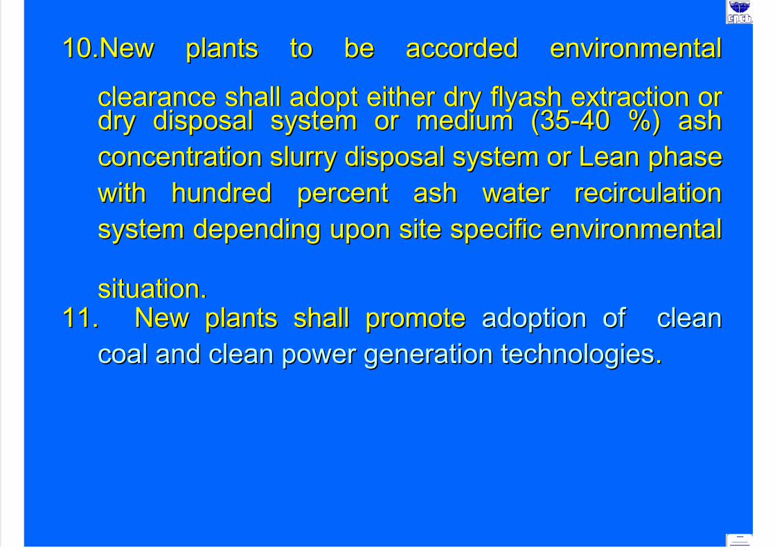
10.New plants to be accorded environmental10.New plants to be accorded environmental
clearance shall adopt either dryclearance shall adopt either dry flyashflyash extraction orextraction ordry disposal system or medium (35dry disposal system or medium (35--40 %) ash40 %) ash
concentration slurry disposal system or Lean phaseconcentration slurry disposal system or Lean phase
with hundred percent ash water recirculationwith hundred percent ash water recirculation
system depending upon site specific environmentalsystem depending upon site specific environmental
situation.situation.11.11. New plants shall promoteNew plants shall promote adoption of cleanadoption of clean
coal and clean power generation technologiescoal and clean power generation technologies..

7/23/2019 Challenges in Iron n Steel by CPCB
http://slidepdf.com/reader/full/challenges-in-iron-n-steel-by-cpcb 11/82
India Ranks World's 2nd largest cement producing country
No. of Large Cement Plants in the country - 123
Total Annual Installed Capacity- 135.55 Million Tonnes
(As on December, 2001)
Annual Cement Production - 98.35 Million Tonnes(As on December, 2001)
India World Average
97 kg/Annum 256 kg/Annum
BACKGROUND OF CEMENT SECTOR
Per Capita Consumption of Cement (1999)

7/23/2019 Challenges in Iron n Steel by CPCB
http://slidepdf.com/reader/full/challenges-in-iron-n-steel-by-cpcb 12/82
S. No. Section Pollution Control Equipment
1. Crusher Bag Filter
2. Raw Mill Bag Filter/ESP
3. Kiln Bag Filter/ESP with GCT
4. Clinker Cooler ESP/Bag Filter with heat
exchanger
5. Coal Mill Bag Filter/ESP
6. Cement Mill Bag Filter/ESP
7. Packing Plant Bag Filter
AIR POLLUTION CONTROL EQUIPMENT
FOR DIFFERENT SECTIONS IN CEMENT INDUSTRY

7/23/2019 Challenges in Iron n Steel by CPCB
http://slidepdf.com/reader/full/challenges-in-iron-n-steel-by-cpcb 13/82
Particulate matter Emission nor to exceed mg/Nm3Plant capacity
in tonnesperday
Protected Area Other Area
<200 250 400
>200 150 250CPCB/SPCB may fix stringent standards, if required as per Air Act, 1981/
Environment (Protection ) Act, 1986
Country Particulate Matter Emission Limit (mg/Nm3)
Australia 50
Germany 50South Africa 120
Switzerland 50
Japan 100
USA 100/ 50
Portugal 100/50
EMISSION STANDARDS IN OTHER COUNTRIES
EMISSION STANDARDS IN INDIA

7/23/2019 Challenges in Iron n Steel by CPCB
http://slidepdf.com/reader/full/challenges-in-iron-n-steel-by-cpcb 14/82
Waste material Generation
(MT/Annum)
Utilization
(MT/Annum)
Flyash 100 6.25
Blast FurnaceSlag
10 5.5
Steel Slag 4.0 0.5
Phospho-gypsum 6.0 2.5
Lime sludge 4.5 0.5
GENERATION OF MAJOR INDUSTRIAL WASTES
& ITS UTILIZATION IN CEMENT MANUFACTURE
IN INDIA (2000-01)
(MT : Million Tonne)
7/23/2019 Challenges in Iron n Steel by CPCB
http://slidepdf.com/reader/full/challenges-in-iron-n-steel-by-cpcb 15/82
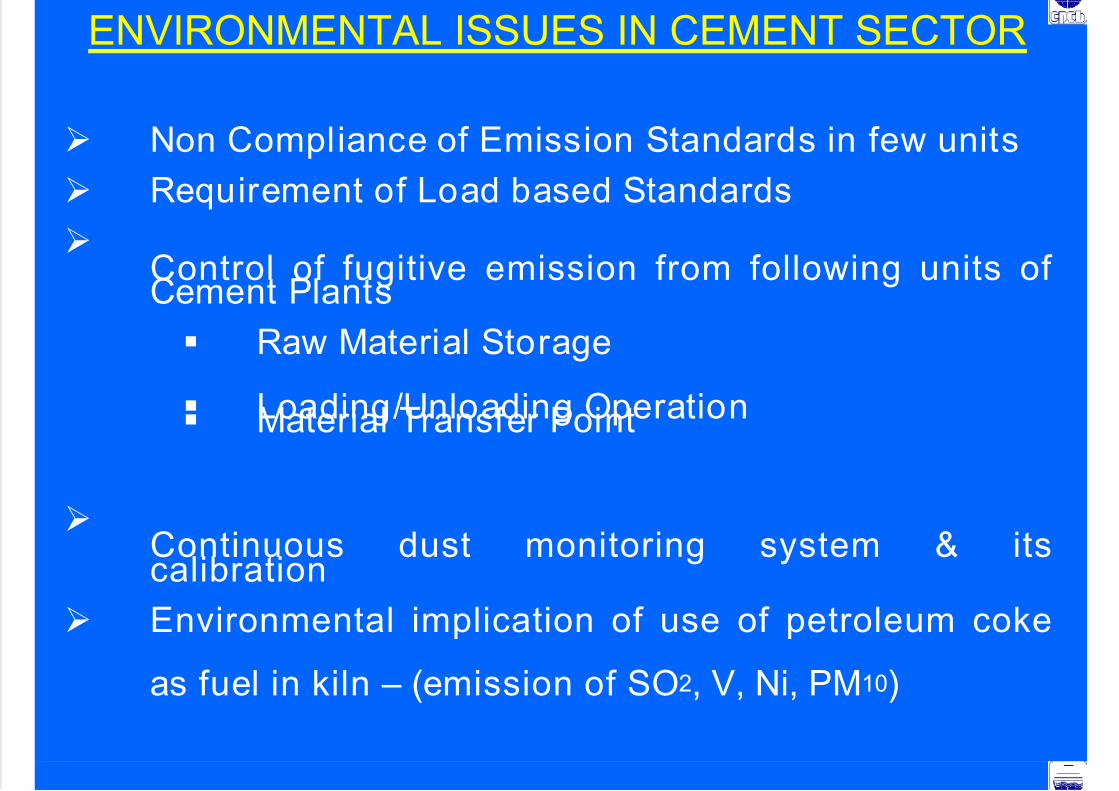
Non Compliance of Emission Standards in few units
Requirement of Load based Standards
Control of fugitive emission from following units ofCement Plants
Raw Material Storage
Loading/Unloading Operation Material Transfer Point
Continuous dust monitoring system & itscalibration
Environmental implication of use of petroleum coke
as fuel in kiln – (emission of SO2, V, Ni, PM10)
ENVIRONMENTAL ISSUES IN CEMENT SECTOR
7/23/2019 Challenges in Iron n Steel by CPCB
http://slidepdf.com/reader/full/challenges-in-iron-n-steel-by-cpcb 16/82
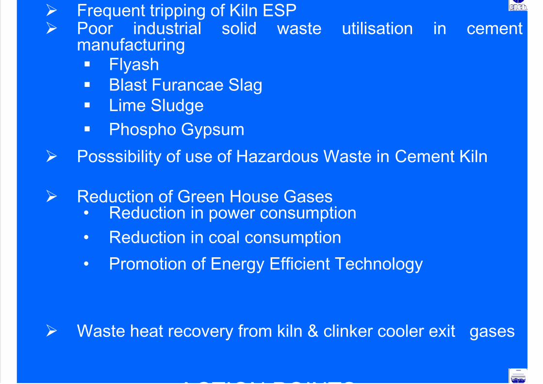
Frequent tripping of Kiln ESP Poor industrial solid waste utilisation in cement
manufacturing Flyash
Blast Furancae Slag
Lime Sludge
Phospho Gypsum
Posssibility of use of Hazardous Waste in Cement Kiln
Reduction of Green House Gases• Reduction in power consumption
• Reduction in coal consumption
• Promotion of Energy Efficient Technology
Waste heat recovery from kiln & clinker cooler exit gases
ACTION POINTS

7/23/2019 Challenges in Iron n Steel by CPCB
http://slidepdf.com/reader/full/challenges-in-iron-n-steel-by-cpcb 17/82
ACTION POINTS
1. Cement Plants located in critically polluted or urbanareas (including 5 km distance outside urban
boundary) will meet 100 mg/Nm3 limit of particulate
matter and continue working to reduce the emission of
particulate matter to 50 mg/Nm3.
2. The new cement kilns to be accorded
NOC/environmental clearance, will meet timplehe limitof 50 mg/Nm3 for particulate matter emission.
3. Load based standards evolved by CPCB to be
implemented.
4. The cement industries will control fugitive emissions
from all the raw material and products storage and
transfer points as per CPCB Guildelines(www.cpcb.nic.in)

7/23/2019 Challenges in Iron n Steel by CPCB
http://slidepdf.com/reader/full/challenges-in-iron-n-steel-by-cpcb 18/82
5. Use of high calorific value hazardouswastes as partial fuel in cement kiln shall
be promoted as per CPCB guidelines.
LIST OF INDUSTRIES WITH LOCATION

7/23/2019 Challenges in Iron n Steel by CPCB
http://slidepdf.com/reader/full/challenges-in-iron-n-steel-by-cpcb 19/82
Source : Questionnaire survey by CPCB (1999-2000)
LIST OF INDUSTRIES WITH LOCATION
LocationS.
No
Name of
Industry Alumina Plant Smelter Power Plant Mines
1. NALCO Damanjodi, Distt
:Koraput, Orissa
Angul, Distt.:
Angul, Orissa
Angul, Distt.:
Angul , Orissa
Panchpatmali Distt.:
Koraput, Orissa
2. BALCO
(Sterlite)
Korba,
Chhattisgarh
Korba,
Chhattisgarh
Korba,
Chhattisgarh
Mainpat, Distt.
Sarguja, Chhatisgarh
3.
INDALCO
i) Belgaum,
Karnataka
ii) Muri,
Jharkhand
(i) Alupuram,
Kalamasssery,
Kerala
(ii) Belgaum (not
in operationsince 1993)
(iii) Hirakud,
Orissa
-
-
Hirakud, Orissa
i) Dugmanwadi,
Maharashtra State
ii) Lohardaga,
Jharkhand
4. HINDALCO Renukoot,
Distt.:Sonbhadra, UP
Renukoot,
Distt.: Sonbhadra,UP
Renusagar,
Distt.:Sonbhadra,
UP
i) Lohardaga,
Jharkhandii) Amarkantak, MP
5. MALCO Metturdam,
Tamilnadu
Metturdam,
Tamilnadu
Metturdam,
Tamil nadu
i)Yercaud, Distt.: Salem
ii)Kolli; Distt: Namakkal
iii)Poondi; Distt.Dindigul
INSTALLED CAPACITY & PROPOSED FUTURE EXPANSION

7/23/2019 Challenges in Iron n Steel by CPCB
http://slidepdf.com/reader/full/challenges-in-iron-n-steel-by-cpcb 20/82
INSTALLED CAPACITY & PROPOSED FUTURE EXPANSION
Installed capacity (TPA) Future Expansion Proposed (TPA)S.
No
.
Name of Smelter
Alumina Aluminiu
m Metal
Aluminium
Products
Alumina Aluminium
Metal
Aluminium
Products
1. NALCO, Angul,
Orissa
8,00,000
(at
Damanjod
i)
2,18,000 2,43,000 15,75,000#
3,45,000 -
2. BALCO Korba,Chhattisgarh
2,00,000 1,00,000 - - - -
3. INDALCO
Alupuram,
Kerala
- 13,500 8,000 - - -
4. INDALCO
Belgaum,
Karnataka
2,70,000 (pots
being to
shifted to
Hirakud)
- - - -
5. INDALCO
Hirakud, Orissa
72,000
(at Muri)
30,000 30,000 - 57,200 57,200
6. HINDALCO
Renukoot, UP
4,50,000 2,42,000 1,33,700 6,60,000 3,56,200 -
7. MALCO
Metturedam, TN
60,000 30,000 69,500 - - -
Total Capacity 18,52,000 7,06,500 5,16,800 - - -
-
Action Points

7/23/2019 Challenges in Iron n Steel by CPCB
http://slidepdf.com/reader/full/challenges-in-iron-n-steel-by-cpcb 21/82
Action Points
S.S.
No.No.
IssuesIssues Action Points Action Points TargetsTargets
Allowing new
Potlines only
with Pre-bakedTechnology
Environmental clearance for
new pot lines to be given by
MoEF, only with pre-bakedtechnology.
1. Technology
Prescribing
maximum size of
the plant
Maximum size of the plant
shall be decided based on the
assimilative capacity of eachplant location.
2. Fluoride
Emissions
Revision of
fluoride
emission
standards
For Soderberg Technology-
2.8 kg/t[1.0 kg/t (VSS) & 1.30 kg/t
(HSS) by Dec 2010]*
For Pre-baked Technology-
0.8 kg/t
*National Task Force will submit the proposal within three months

7/23/2019 Challenges in Iron n Steel by CPCB
http://slidepdf.com/reader/full/challenges-in-iron-n-steel-by-cpcb 22/82
S. No Issues Action Points Targets
Phasing out Wet
Scrubbing Systemfor fluoride
With Immediate effect.
Monitoring of
fugitive emissionsfrom pot rooms
Monitoring of secondary
fluoride emission shall bedone as per CPCB guidelines.
3. Fluoride
Consump-
t ion
Fluorideconsumption per
tonne of aluminiumproduced (as F-)
[ForSoderberg Te c hno lo g y -
15 kg/t
For Pre-baked Tec hno lo g y -
10 kg/t
4. Ambient
Fluoride
Forage fluoride
standards
• Twelve consecutive months
average- 40 ppm
• Two consecutive months
average – 60 ppm
• One month – 80 ppm

7/23/2019 Challenges in Iron n Steel by CPCB
http://slidepdf.com/reader/full/challenges-in-iron-n-steel-by-cpcb 23/82
S.
No.
Issues Action Points Targets
Setting up a centralized
SPL treatment & disposal
facility with aluminium
fluoride recovery andutilisation of SPL in
steel/cement industries
With immediate effect
Limit for pot life (for new
pots installed after
December 31, 2003
[2500 days (average)]
5. Spent Pot
Lining (SPL)
SPL (Carbon &
Refractory) to be
disposed in Secured
Landfill
With immediate effect.
However, the carbon
portion of SPL may be used
in Cement Plant as partialfuel.

7/23/2019 Challenges in Iron n Steel by CPCB
http://slidepdf.com/reader/full/challenges-in-iron-n-steel-by-cpcb 24/82
S.No.
Issues Action Points Targets
Phasing out Wet disposal With immediate effect.6. Red Mud
Red Mud Utilisation
7. Anode
Baking Oven
Achieving particulate
matter limit of 50 mg/Nm3
With immediate effect.
INTEGRATED IRON AND STEEL PLANTS IN INDIA

7/23/2019 Challenges in Iron n Steel by CPCB
http://slidepdf.com/reader/full/challenges-in-iron-n-steel-by-cpcb 25/82
Installed Capacity – Million Tonne per Annum
Based on BF Technology
Steel Authority of India Limited (SAIL)
Bhi lai Steel Plant (BSP) 4.0 MTPA
Bokaro Steel Plant (BSL) 4.0 MTPA
Rourkela Steel Plant (RSP) 2.5 MTPA
Indian Iron & Steel Company (IISCO) 1.0 MTPA
Durgapur Steel Plant (DSP) 1.6 MTPA
Rastriya Ispat Nigam Ltd. (RINL)
Visakapatnam Steel Plant 3.0 MTPA
Tata Iron & Steel Co. Ltd. (TISCO)
Tata Steel 3.5 MTPA
Based on COREX Technology
Jindal Vijaynagar Steel Ltd. (JVSL) 3.0 MTPA
Based on DRI
ESSAR Steel 2.0 MTPA
EMISSION STANDARDS :

7/23/2019 Challenges in Iron n Steel by CPCB
http://slidepdf.com/reader/full/challenges-in-iron-n-steel-by-cpcb 26/82
StandardsParameter
NewBatteries
ExistingBatteries
Fugitive Visible Emissions
(a) Leakage from door 5 (PLD)* 10 (PLD)*
(b) Leakage from charging lids 1 (PLL)* 1 (PLL)*
(c) Leakage from AP Covers 4 (PLO)* 4 (PLO)*
(d) Charging emission (second/charge) 16
(withHPLA)*
50
(withHPLA)*
Stack Emission of Coke Oven
(a) SO2(mg/Nm3) 800 800
(b) NOx, (mg/Nm3) 500 500
(c) SPM, (mg/Nm3) 50 50
(a) SPM emission during charging (stack emission) mg/Nm3 25 25
(b) SPM emission during coke pushing (stack emission)gm/ton of coke
5 5
COKE OVEN PLANTS (BY PRODUCT RECOVERY TYPE)MoEF Notif ication G.S.R. 631(E), dated 31st October, 1997
Contd…

7/23/2019 Challenges in Iron n Steel by CPCB
http://slidepdf.com/reader/full/challenges-in-iron-n-steel-by-cpcb 27/82
StandardsParameter
NewBatteries
ExistingBatteries
Sulphurin Coke Oven gas used for heating (mg/Nm3) 800 800
Emission for quenching operation
Particulate matter gm/MT of coke produced 50 50Benzo-Pyerine (BOP) concentration in work zone air (ug/m3)
Battery area (top of the battery) 5 5
Other units in coke oven plant 2 2
Ambient standards (ng/m3) 10 10
ENVIRONMENTAL STANDARDS FOR COKE OVEN PLANTS – USEPA
7/23/2019 Challenges in Iron n Steel by CPCB
http://slidepdf.com/reader/full/challenges-in-iron-n-steel-by-cpcb 28/82
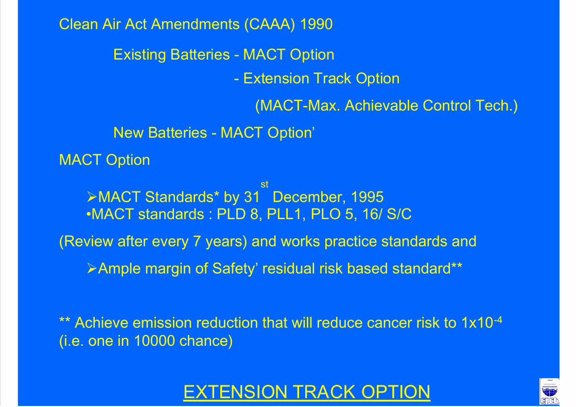
Clean Air Act Amendments (CAAA) 1990
Existing Batteries - MACT Option
- Extension Track Option
(MACT-Max. Achievable Control Tech.)
New Batteries - MACT Option’
MACT Option
MACT Standards* by 31st
December, 1995•MACT standards : PLD 8, PLL1, PLO 5, 16/ S/C
(Review after every 7 years) and works practice standards and
Ample margin of Safety’ residual risk based standard**
** Achieve emission reduction that will reduce cancer risk to 1x10⁻⁴
(i.e. one in 10000 chance)
EXTENSION TRACK OPTION

7/23/2019 Challenges in Iron n Steel by CPCB
http://slidepdf.com/reader/full/challenges-in-iron-n-steel-by-cpcb 29/82
Extension in complying residual risk based standardsupto 1.1.2020subject to:
To qualify for the extension the existing batteries have to meet
•By 15.11.93
8 PLD, 1PLL, 5PLO and 16 S/C
•By 1.1.98 (LAER)
3 PLD (5PLD for tall), 1 PLL, 4 PLO, 16 S/C
(with an exclusion for just charged door)
(LAER II) by 1.1.2010 yet to be fixed
USEPA to evaluate for the installation of New Batteries- JEWELL Thompson Design non recovery oven
- Other non recovery tech.
- Other Appropriate emission control
ACTION POINTS

7/23/2019 Challenges in Iron n Steel by CPCB
http://slidepdf.com/reader/full/challenges-in-iron-n-steel-by-cpcb 30/82
1. Coke Oven Plants
To meet the parameters PLD (% leaking doors), PLL(%leaking lids), PLO (% leaking off take), of the notified
standards.
Industry will submit time bound action plan and PERT Chartalong with the Bank Guarantee for the implementation of the
same.
- To rebuild at least 40% of the coke oven batteries* in next 10years (December 2012).
2. Steel Melt ing Shop
Fugitive emissions -To reduce 100% by March 2008 (including
installation of secondary de-dusting facilit ies)
* As per rebuilding schedule submitted to CPCB / MoEF.Contd..
3 Bl t F

7/23/2019 Challenges in Iron n Steel by CPCB
http://slidepdf.com/reader/full/challenges-in-iron-n-steel-by-cpcb 31/82
3. Blast Furnace
Direct inject of reducing agents
4. Solid Waste / Hazardous Waste Management
Utilization of Steel Melting Shop (SMS) / Blast Furnace (BF)Slag
Hazardous WasteCharge of tar sludge / ETP sludge to Coke Oven
Inventorization of the Hazardous Waste as per Hazardous
Waste (M&H) Rules, 1989 as amended from time to time andimplementation of the Rules
(Tar sludge, acid sludge, waste lubricating oil and used type
fuel falls in the category of Hazardous Waste.)
Contd..
5. Water conservation / Water Pollution

7/23/2019 Challenges in Iron n Steel by CPCB
http://slidepdf.com/reader/full/challenges-in-iron-n-steel-by-cpcb 32/82
• To reduce specific water consumption to 5 m3/t for long
products and 8 m3/t for flat products.• To operate the CO-BP effluent treatment plant efficiently to
achieve the notified effluent discharge standards.
6. Installation of Continuous stack monitoring system & its
calibration in major stacks, on line ambient air quality
monitoring stations.
7. To operate the existing pollution control equipments efficiently
and to have proper record keeping of pollution control
equipment run hours, failure time and efficiency with
immediate effect. Compliance report to be submitted to CPCB /SPCB every three months
8. Implementation of recommendations of Life Cycle Assessment(LCA) study sponsored by MoEF.Contd..

7/23/2019 Challenges in Iron n Steel by CPCB
http://slidepdf.com/reader/full/challenges-in-iron-n-steel-by-cpcb 33/82
9. The industry will initiate the steps to adopt the following clean
technology/measures to improve the performance of the
industry towards production, energy and environment.
– Energy recovery of top Blast Furnace (BF) gas.
– The use of Tar-free runner linings. – Cast House de-dusting (tap holes, runners, skimmers, ladle
charging points)
– Suppression of fugitive emissions using nitrogen gas or anyother inert gas.
– To study the possibility of slag and fly ash transportation back to
the abandoned mines to fill up the cavities through emptyrailway wagons when they return and its implementation.
– Yearly progress report on these issues will be submitted by the
industry to CPCB and MoEF.Contd..

7/23/2019 Challenges in Iron n Steel by CPCB
http://slidepdf.com/reader/full/challenges-in-iron-n-steel-by-cpcb 34/82
– Processing of the waste containing flux & ferrous wastes
through Waste recycling plant.
– To implement rain water harvesting.
– Reduction of Green House Gases by:
. Reduction in power consumption
. Use of By-production gases for power generation
· Promotion of Energy Optimisation Technology,
including energy audit
–
To set targets for Resource Conservation such as Rawmaterial, energy and water consumption to match
International Standards
Contd..
7/23/2019 Challenges in Iron n Steel by CPCB
http://slidepdf.com/reader/full/challenges-in-iron-n-steel-by-cpcb 35/82
- Up-gradation in the monitoring analysis facilities forair and water pollutants. Also to impart elaboratetraining to the manpower in the environmental
monitoring laboratories, so as realistic data can beobtained.
- To improve house keeping.

7/23/2019 Challenges in Iron n Steel by CPCB
http://slidepdf.com/reader/full/challenges-in-iron-n-steel-by-cpcb 36/82
SPONGE IRON PLANTSSPONGE IRON PLANTS – –
POLLUTION CONTROL STANDARDPOLLUTION CONTROL STANDARD
Process in Brief – Sponge Iron Plant

7/23/2019 Challenges in Iron n Steel by CPCB
http://slidepdf.com/reader/full/challenges-in-iron-n-steel-by-cpcb 37/82
• Inside the rotary kiln, the DRI gases flow counter-current to the
kiln feed. The temperature at the product discharge end in a
rotary kiln is about 950-1050oC compared to 750-900oC towards
the feed end. The counter-current flow of hot DRI gases enable it
to remove the moisture content from feed. The hot DRI gases
contains huge amount of fine dust comprising oxides and
unburnt carbon and toxic carbon monoxide. It needs treatment
before discharging into the atmosphere
• The raw material feed side of rotary DRI Kiln has a naturalstructure below the After Burner Chamber (ABC) that acts as
Dust Settling Chamber (DSC). About 15-20% coarse dust settles
in DSC by means of gravity. In ABC, the CO content of gases is
converted to CO2. This conversion process is exothermic and thetemperature of gases rises to 1000-1050oC
• Some plants (very few) have Gas Conditioning Tower (GCT)
followed by pollution control equipment and cleaned gas isemitted through stacks
Air pollution mitigation measuresAir pollution mitigation measures

7/23/2019 Challenges in Iron n Steel by CPCB
http://slidepdf.com/reader/full/challenges-in-iron-n-steel-by-cpcb 38/82
• In case no pollution control are installed
by the unit the particulate matter emission
was observed around 25 gm/Nm3.
• This indicated that installation of pollutioncontrol devices is must to protect the
environment. The pollution control
devices like ESPs, Bag filters, and wetscrubbers installed by the industries.
Air pollution mitigation measures Air pollution mitigation measures

7/23/2019 Challenges in Iron n Steel by CPCB
http://slidepdf.com/reader/full/challenges-in-iron-n-steel-by-cpcb 39/82
The sources of fugitive dust generation are:
• Raw Material Handling Yard (unloading,
stacking, reclaiming operations)
• Product discharge system (cooler
discharge conveyors, transfer points, junction house, screens, magnetic
separators, storage silos, truck loading
and packing operations).
Fugitive dust generation
Water Pollution Mitigation MeasuresWater Pollution Mitigation Measures

7/23/2019 Challenges in Iron n Steel by CPCB
http://slidepdf.com/reader/full/challenges-in-iron-n-steel-by-cpcb 40/82
The water requirement in rotary kiln DRI plant ismainly for cooling the discharge feed from 950-1050oC
to below 100oC. Water is continuously sprinkled over
the rotary cooler shell and is allowed to fall on asettling tank located below the rotary cooler/ near the
cooler. In ABC water is sprayed through the nozzles in
the form of spray to control the temperature of thegases.
Make-up water is added in the tank to cool the hot
water and compensate evaporation loss. The waterfrom settling tank is re-circulated for sprinkling over
the rotary cooler
The water requirement varies from 4-6 m3/ t of DRI.
gg
Solid Waste GenerationSolid Waste Generation
7/23/2019 Challenges in Iron n Steel by CPCB
http://slidepdf.com/reader/full/challenges-in-iron-n-steel-by-cpcb 41/82
• Char
• Dedusting dust from pollution control
equipment of Product handling area• Kiln accretion waste
• Dedusting dust from pollution controlequipment of Cooler discharge area
•
Scrubber sludge (scrubber is installed aspollution control equipment of Kiln)
• Process dust from pollution control
equipment of Kiln
ENVIRONMENTAL STANDARDS

7/23/2019 Challenges in Iron n Steel by CPCB
http://slidepdf.com/reader/full/challenges-in-iron-n-steel-by-cpcb 42/82
The standards will be applicable with effect from the
date of notification to all new, green field units set up
after the date of this notification and all expansion/
modernisation of existing units taken up after thedate of the notification. However, the existing units
shall install effective pollution control system within
six months and shall conform to the standards, after
six months of the date of notification.
ENVIRONMENTAL STANDARDS

7/23/2019 Challenges in Iron n Steel by CPCB
http://slidepdf.com/reader/full/challenges-in-iron-n-steel-by-cpcb 43/82
1.0 Emission Standards
1.1 Stack Emission : 100 mg/nm3 (Coal based)*
Standards for Kiln 50 mg/Nm3 (Gas based)
*12% CO2 correction
Combustion Efficiency (CE) : shall be atleast 99.9% and be
of After Burner Chamber (ABC) computed as below:
CE= % CO2//[%CO2 + %CO]*100
1.2 Stack Emission Standards for de-dusting units

7/23/2019 Challenges in Iron n Steel by CPCB
http://slidepdf.com/reader/full/challenges-in-iron-n-steel-by-cpcb 44/82
Particulate matter (PM) : 100 mg/Nm3
Stack Height ** (minimum) Coal/gas 30.0 m** Stack height shall be calculated as H=14.0 Q0.3 where Q isemission of Sulphur Dioxide (SO2) in kg/hr.ie.
SO2 (kg/hr) Height (metre)upto 12.68 3012.69 – 33.08 4033.09 – 69.06 5069.07 – 127.80 60
127.81 – 213.63 70
1.3 Fugitive Emission Standards
(Rotary Kiln/ Particulate Existing NewDe-dusting unit) matter unit Unit
Note:Note:(i) the existing industry shall comply with the standard of 2000
µg/m3
after one year from the date of notification.(ii) Fugitive Emission shall be monitored at a distance 10.0 metrefrom the source of fugitive emission.
Fugitive Emission Monitoring Location

7/23/2019 Challenges in Iron n Steel by CPCB
http://slidepdf.com/reader/full/challenges-in-iron-n-steel-by-cpcb 45/82
S.N Area Monitoring Location
1. Raw material
handling area
Wagon tippler, Screen area,
Transfer Points, Stock Bin area
2. Crusher area Crushing plant, vibrating screen,
transfer points
3. Raw material feed
area
Feeder area, Mixing area, transfer
points
4. Cooler dischargearea
Over size discharge area, TransferPoints
5. Product
processing area
Intermediate stock bin area.
Screening plant, MagneticSeparation unit, Transfer Points,
Over size discharge area, Product
separation area, Bagging area
6. Other areas Areas as specified by StatePollution Control Board
2.0 Effluent Discharge Standards

7/23/2019 Challenges in Iron n Steel by CPCB
http://slidepdf.com/reader/full/challenges-in-iron-n-steel-by-cpcb 46/82
(i) All efforts should be made to reuse and re-circulate thewater and to maintain zero effluent discharge.
(ii) Storm water / garland drain should be provided in theplant.
(iii) In case of maintenance/ cleaning of the system the
settling tanks effluent of wet scrubbing system orre-circulation system if require to be discharged,
should be treated suitably to conform to the following
standards:
pH : Between 5.5 to 9.0
Total Suspended Solids (TSS) : 100 mg/l
Chemical Oxygen Demand (COD) : 250 mg/lOil and Grease (O&G) : 10 mg/l
GUIDELINES

7/23/2019 Challenges in Iron n Steel by CPCB
http://slidepdf.com/reader/full/challenges-in-iron-n-steel-by-cpcb 47/82
1.0
.0
Air Pollution
ir Pollution
1.1
.1
Stack Emission from Kiln
tack Emission from Kiln
(i) Adequately designed ESP or any other adequate air
pollution control system/combination of system shouldbe installed to achieve the prescribed stack emission
standards.
As installation and operation of Pollution ControlEquipment for plants with less than 100 TPD capacity is
not economically viable, therefore, it is recommended
that plants with less than 100 TPD shall not be permittedin future.
Program for phasing out old plants having capacity less
than 100 TPD shall be worked out by the State PollutionControl Board.
GUIDELINES (contd..)
7/23/2019 Challenges in Iron n Steel by CPCB
http://slidepdf.com/reader/full/challenges-in-iron-n-steel-by-cpcb 48/82
(ii) All Pollution control equipment should be provided
with separate electricity meter and totaliser for
continuous recording of power consumption. The
amperage of the ID fan should also be recordedcontinuously. Non-functioning of Pollution control
equipment should be recorded in the same
logbook along with reasons for not running the
Pollution Control Equipment.
(iii) The safety cap/emergency stack of rotary kiln type
plant, which is generally installed above the AfterBurner Chamber (ABC) of feed end column should
not be used for discharging untreated emission,
bypassing the air pollution control device.
GUIDELINES (contd..)

7/23/2019 Challenges in Iron n Steel by CPCB
http://slidepdf.com/reader/full/challenges-in-iron-n-steel-by-cpcb 49/82
(iv) In order to prevent bypassing of emissions through safety
cap and non-operation of ESP or any other pollution
control device, software controlled interlocking facility
should be provided on the basis of real time data from the
plant control system, to ensure stoppage of feedconveyor, so that, feed to the kiln would stop
automatically, if safety cap of the rotary kiln is opened or
ESP is not in operation. The system should be able to
take care of multiple operating parameters and their interrelations to prevent any possibility of defeating the basic
objective of the interlock. The system should be foolproof
to prevent any kind of tempering. The software basedinterlocking system, proposed to be installed by industry
should be get approved by the concerned State Pollution
Control Board, for its adequacy, before installation by the
industry.
GUIDELINES (contd..)

7/23/2019 Challenges in Iron n Steel by CPCB
http://slidepdf.com/reader/full/challenges-in-iron-n-steel-by-cpcb 50/82
(v) Mechanical operated system for t imely collectionand removal of the flue dust generated in ESP or
any other pollution control device shall be
installed.
1.2 Stack Emission from de dusting units
All de-dusting units should be connected to astack having a minimum stack height of 30 m.
Sampling porthole and platform etc. shall be
provided as per CPCB emission regulation to
facilitate stack monitoring. De-dusting units can
also be connected to ABC Chamber and finally
emitted through common stack with kiln off-gas
emissions.
GUIDELINES (contd..)

7/23/2019 Challenges in Iron n Steel by CPCB
http://slidepdf.com/reader/full/challenges-in-iron-n-steel-by-cpcb 51/82
1.3 Fugitive Emission
The measurement may be done, preferably on
8-hour basis with high volume sampler. However,
depending upon the prevalent conditions at the
site, the period of measurement can be reduced.
2.0 Effluent Discharge
(i) All efforts should be made to reuse and re-circulate
the water and to maintain zero effluent discharge.
(ii) Storm water / garland drain should be provided in
the plant.
3.0 Noise Control
The industry should take measures to control the
Noise Pollution so that the noise level standards
already notified for Industrial area are complied.
GUIDELINES (contd..)

7/23/2019 Challenges in Iron n Steel by CPCB
http://slidepdf.com/reader/full/challenges-in-iron-n-steel-by-cpcb 52/82
4.0 Solid Waste Management
Char
Char should be mixed with coal or coal washery rejects and used as
fuel in Fluidized Bed Combustion Boilers (FBC) for generation of
power. The plants having capacity 200 TPD and above should installFluidized Bed Combustion Boilers (FBC) for generation of power.
Also the smaller capacity individual Sponge Iron Plants (Capacity
upto 100 TPD) and operating in cluster can collectively install
common Fluidized Bed Combustion Boilers (FBC) for powergeneration. The Sponge Iron Plant are free to explore other options /
possibilities to use char for generation of power. Char can be sold to
local entrepreneurs for making coal briquettes. It can also be mixed
with coal fines, converted to briquettes and used in brick kilns.
Under no circumstances char should be disposed off in agricultural
fields/other areas. Logbook for daily record, of Char production and
usage must be maintained by the industry and the record shall bemade available to officials of CPCB/SPCB/PCC during inspection.
GUIDELINES (contd..)

7/23/2019 Challenges in Iron n Steel by CPCB
http://slidepdf.com/reader/full/challenges-in-iron-n-steel-by-cpcb 53/82
Kiln Accretions
The kiln accretions are heavy solid lumps and can be
used as sub- base material for road construction orlandfill, after ascertaining the composition for its
suitability and ensuring that it should not have any
adverse environmental impact.
Gas Cleaning Plant (GCP)/Scrubber Sludge
The sludge should be compacted and suitably disposedoff after ascertaining the composition for its suitability
and ensuring that it should not have any adverse
environmental impact.
GUIDELINES (contd..)

7/23/2019 Challenges in Iron n Steel by CPCB
http://slidepdf.com/reader/full/challenges-in-iron-n-steel-by-cpcb 54/82
Flue Dust / Fly ashFlue dust is generated from air pollution control
system i.e. ESP or any other air pollution control
system installed with kiln. Secondary flue dust is alsogenerated from Bag Filters or any other air pollution
control equipment installed with Raw Material
Handling, Coal Crusher, Cooler Discharge and Producthouse unit. The reuse/ recycling of the flue dust
generated / collected may be explored and suitably
implemented.
Fly ash brick manufacturing plant should be install for
fly ash utilization. Fly ash can be utilized in cement
making by Cement industry also.
Bottom Ash
GUIDELINES (contd..)

7/23/2019 Challenges in Iron n Steel by CPCB
http://slidepdf.com/reader/full/challenges-in-iron-n-steel-by-cpcb 55/82
Bottom Ash
Bottom ash may have objectionable metallic compounds, thereforeshould be stored in properly designed landfills as per CPCB
guidelines to prevent leaching to the sub-soil and underground
aquifer.
General(a) Solid waste management program should be prepared with thrust
on reuse and recycling. Solid waste disposal site should be
earmarked within the plant premises. The storage site of solid
waste should be scientifically designed keeping in view that the
storage of solid waste should not have any adverse impact on the
air quality or water regime, in any way.
(b) The various types of solid wastes generated should be stored
separately as per CPCB guidelines so that it should not
adversely affect the air quality, becoming air borne by wind orwater regime during rainy season by flowing along with the
storm water.
GUIDELINES (contd..)
7/23/2019 Challenges in Iron n Steel by CPCB
http://slidepdf.com/reader/full/challenges-in-iron-n-steel-by-cpcb 56/82
5.0 Raw Material handling and Preparation
(a) Unloading of coal by trucks or wagons should be carried
out with proper care avoiding dropping of the materials
from height. It is advisable to moist the material by
sprinkling water while unloading.
(b) Crushing and screening operation should be carried out in
enclosed area. Centralized de- dusting facili ty (collection
hood and suction arrangements followed by de-dusting
unit like bag filter or ESP or equally effective method or
wet scrubber and finally discharge of emission through a
stack) should be provided to control Fugitive ParticulateMatter Emissions. The stack should confirm to the
emission standards notified for de-dusting units. Water
sprinkling arrangement should be provided at raw material
heaps and on land around the crushing and screeningunits.
( ) W k i l di th d di th l t h ll b
GUIDELINES (contd..)

7/23/2019 Challenges in Iron n Steel by CPCB
http://slidepdf.com/reader/full/challenges-in-iron-n-steel-by-cpcb 57/82
(c) Work area including the roads surrounding the plant shall be
asphalted or concreted.
(d) Enclosure should be provided for belt conveyors and transfer
points of belt conveyors.
The above enclosures shall be rigid and permanent (and not
of flexible/ cloth type enclosures) and fit ted with self- closing
doors and close fitting entrances and exits, where conveyors
pass through the enclosures. Flexible covers shall be
installed at entry and exit of the conveyor to the enclosures,
minimizing the gaps around the conveyors.
In the wet system, water sprays/ sprinklers shall be provided
at the following strategic locations for dust suppression
during raw material transfer:
- Belt conveyor discharge/ transfer point- Crusher/screen discharge locations
GUIDELINES (contd..)

7/23/2019 Challenges in Iron n Steel by CPCB
http://slidepdf.com/reader/full/challenges-in-iron-n-steel-by-cpcb 58/82
6.0 Waste Heat Recovery Boiler (WHRB)
Sponge Iron Plants of capacity more than 100 TPD
kilns shall use Waste Heat Recovery Boiler (WHRB)
for generation of power.
7.0 Cooler Discharge and Product Separation Unit
Permanent and rigid enclosures shall be provided
for belt conveyors and transfer points of belt
conveyors. Dust extraction cum control system
preferably bag filters or ESP to arrest product loss
in cooler discharge and product separation area
shall be installed.
8 0 Char based Power Plant
GUIDELINES (contd..)

7/23/2019 Challenges in Iron n Steel by CPCB
http://slidepdf.com/reader/full/challenges-in-iron-n-steel-by-cpcb 59/82
8.0 Char based Power Plant
For plant having capacity of 200 TPD of cumulative kiln capacity, the
power production through FBC boiler using char as a part of fuel, is
a viable option. Power generation through FBC boiler using char as a
part of fuel be implemented in a phased manner within 4 years of
commissioning and targeting for 100% utilization of char.
Individual Sponge Iron Plants of capacity upto 100 TPD and
located in cluster can install a common char based power
plant collectively.
9.0 New Sponge Iron Plants
(i) No New Sponge Iron Plant will be commissioned without installationof Pollution control systems as stipulated in the Standards. The
concerned State Pollution Control Board will accord consent to
operate only after Physical verification of the adequacy of the
Installed pollution control systems for meeting the standards andstipulated conditions in the consent to establish.
(ii) All kil h ll h th i d d t t k ith th kil
GUIDELINES (contd..)

7/23/2019 Challenges in Iron n Steel by CPCB
http://slidepdf.com/reader/full/challenges-in-iron-n-steel-by-cpcb 60/82
(ii) All new kilns shall have the independent stack with the kiln or
multi-flue stacks in case two or more kilns are joining the samestack for better dispersion of pollutants.
(iii) Any entrepreneur having more than 2x100 TPD kiln may install
WHRB for power generation, as it’s a techno-economic viableoption.
For plants having capacity of 200 TPD or more, power generation
using char in FBC Boiler as part of fuel is techno-economicviable option, therefore, new plants must install FBC boiler for
power generation at the time of installation of the industry.
(iv) Any new sponge iron plant being installed along with the otherdownstream facilities of converting the sponge iron into steel
with/without further processing the steel should meet the target
of 100% utilization of sensible heat of DR (Direct Reduction) Gas
and Char for power generation. Wet scrubbing system for kilnoff-gas treatment for such plants should not be opted.
10 0 General Guidelines
GUIDELINES (contd..)

7/23/2019 Challenges in Iron n Steel by CPCB
http://slidepdf.com/reader/full/challenges-in-iron-n-steel-by-cpcb 61/82
10.0 General Guidelines
(a) Extensive plantation/Green belt shall be developed along theroads and boundary line of the industry. A minimum 15 m
width Green Belt along the boundary shall be maintained.
However, the green belt may be designed scientifically
depending upon the requirement and local and mix species of
plants may be selected for the green belt.
(b) Monitoring of stack emissions, fugitive emissions, trade
effluent and noise level shall be done as per CPCBregulations.
(c) Pollution control systems shall be operated as an integral part
of production to ensure minimum emissions. Pollution ControlSystem shall start before conveyor operation/operation of
plant. Similarly pollution control system shall be stopped only
after completion of conveyor operation/operation of plant so
that possibility of dust settlement in ducts can be eliminated.Continuous evacuation of dust (from Dust catchers, ESPs,
Bag filter hopper etc.) shall be organized.
11.0 Siting Guideline for Sponge Iron Plants
GUIDELINES (contd..)

7/23/2019 Challenges in Iron n Steel by CPCB
http://slidepdf.com/reader/full/challenges-in-iron-n-steel-by-cpcb 62/82
11.0 Siting Guideline for Sponge Iron Plants
Siting of new sponge iron plants shall be as per respective
State Pollution Control Board guidelines. However the
following aspects shall also be considered:
(a) Residential habitation (residential localities/ village) andecologically and/or otherwise sensitive areas: A minimumdistance of at least 1000 m (1.0 km) to be maintained.
(b) The location of Sponge Iron Plant should be at least 500 maway from National Highway and State Highway.
(c) Radial distance between two Sponge Iron Plants shouldbe 5 km for plants having capacity 1000 TPD or more.
(d) Sponge Iron Plants can be established in designated industrialareas / Estates as notified by State Govt.
(e) If any plant/clusters of plants are located within 1 km from any
residential area/ village they may be shifted by State PollutionControl Board/ State Govt. in a phased manner for which a timebound action plan is to be prepared by SPCBs.
Specific Recommendation for Industrial
Pollution Control in Chhattisgarh

7/23/2019 Challenges in Iron n Steel by CPCB
http://slidepdf.com/reader/full/challenges-in-iron-n-steel-by-cpcb 63/82
Pollution Control in Chhattisgarh
A. Silatara/Raipur, Raigarh area
1. No new sponge iron plant to be permitted in
Siltara – Raipur area.
2. Sponge iron plants shall be permitted in other
areas only after adoption of clean technology(www.cpcb.nic.in) and installation of WHRB and
AFBC/FBC boiler for char utilization for power
generation.
3. Existing sponge iron plants in Siltara area to be
directed to install AFBC/FBC boiler for use of
char in a time bound manner by ChhattisgarhPollution Control Authority.
4. Proper ash management programme to be drawn

7/23/2019 Challenges in Iron n Steel by CPCB
http://slidepdf.com/reader/full/challenges-in-iron-n-steel-by-cpcb 64/82
giving emphasis' to utilise ash in cement makingetc.
5. Fugitive emission from the sponge iron plants tobe controlled as per CPCB guidelines.
6. Carrying capacity study in Siltara industrial areato be conducted specially to see the impact of
industries in Raipur city.
7. Integrated steel plants in Chhattisgarh to follow
the emission standards notified under EP Act and
CREP guidelines.
8. Toxic emission (PAH, VOC etc) from Coke Oven
l t t b t ll d CPCB id li

7/23/2019 Challenges in Iron n Steel by CPCB
http://slidepdf.com/reader/full/challenges-in-iron-n-steel-by-cpcb 65/82
plants to be controlled as per CPCB guidelines.
9. Slag generated from steel melting shop (SMS) to
be properly managed.
10. Blast Furnace Slag to be sent to cement plant for
utilization.
11. Non recovery coke oven plants should
install WHRB for power generation.
12. Iron ore mining industry should follow strictly the
standard and guidelines of CPCB.
B. Korba Area1. In Korba area large number of coal based power
station are being setup.

7/23/2019 Challenges in Iron n Steel by CPCB
http://slidepdf.com/reader/full/challenges-in-iron-n-steel-by-cpcb 66/82
g p
Based upon regional environmental impact study the
requirement of SO2,Nox and Mercury emission control
to be studied.
2. Ash utlisation plan should be drawn with all stake
holders for proper ash management following may
be considered.• Use of benefeciated coal for power generation.
• Dry collection of ash for cement making.
• Cement grinding unit to be located close to powerplant to utlise ash.
• Power plants to be encouraged to setup their own
cement plants for utilization of ash.• Clean coal technology to be promoted.
3. For Aluminium plant the secondary

7/23/2019 Challenges in Iron n Steel by CPCB
http://slidepdf.com/reader/full/challenges-in-iron-n-steel-by-cpcb 67/82
p y
emission of fluoride to be controlled tomeet the total fluoride emission as 0.8
Kg/ton.
4. Spent pot lining which is hazardous waste
to be disposed as per Hazardous Waste
Management Rules and carbon portionmay be utilise in cement plant as partial
fuel.
C. General Issue
1 Thick Green Belt to be planted between Raipur and Siltara to

7/23/2019 Challenges in Iron n Steel by CPCB
http://slidepdf.com/reader/full/challenges-in-iron-n-steel-by-cpcb 68/82
1. Thick Green Belt to be planted between Raipur and Siltara to
prevent the fugitive emission from industrial area to Raipur city.
2. In Siltara industrial area all the Kaccha road to be cemented.
3. Continuous Air Quality Monitoring Station to be setup at
Siltara, Raipur, Raigarh, Korba and other industrial area
jointly by industries and data to be displayed in SPCB’swebsite.
4. TSDF facility should be setup immediately in Siltara/Korba
area for disposal of Hazardous wastes.
5. Chhattisgarh Pollution Control Committee may initiate
Ambient Air Quality Monitoring based upon new draft Ambient Air Quality Standards.
M/s.M/s. VinayakVinayak Steels,Steels, Mahaboobnagar Mahaboobnagar District (100 TPD):District (100 TPD):
Case Study

7/23/2019 Challenges in Iron n Steel by CPCB
http://slidepdf.com/reader/full/challenges-in-iron-n-steel-by-cpcb 69/82
This industry has provided Emission Control Equipments to all the
sources including fugitive emissions by concealing the following
areas Screen house
Crusher house
Stock house
Intermediate bin
Product house
Central Burner platform
Cooler discharge building Belt conveyors
Raw material & Finished product handling
Waste products handling.
yy , gg ( )( )
This industry was inspected and made the followingThis industry was inspected and made the followingobservations:observations:
PROCESS (Coal Based)

7/23/2019 Challenges in Iron n Steel by CPCB
http://slidepdf.com/reader/full/challenges-in-iron-n-steel-by-cpcb 70/82
• Basic raw materials, for the production of Sponge Iron,
are hematite (Fe2O3), coal (C) and dolomite (CaO &
MgO). These three raw materials are crushed and
screened to a size fraction of 5 to 18 mm and -5mm.
These sized material is fed in to the rotary kiln through
feed tubes.
• The rotary kiln is a cylindrical structure with 3 meters
diameter and 42 meters length, the entire kiln is divided
into 7 zones and each zone is provided by a shell airfan.
PROCESS (contd.)

7/23/2019 Challenges in Iron n Steel by CPCB
http://slidepdf.com/reader/full/challenges-in-iron-n-steel-by-cpcb 71/82
• These fans pump the air in to the kiln which isnecessary for the process.
• The kiln is Horizontal, and is supported by supportrollers and is rotated by an Electrical Motor of 100 HP.
• The raw materials take 8 to 12 hours to travel from thefeed end to the discharge end, during this travel ore getsheated up in first 3 zones and starts reduction from the
4th zone onwards.
• Finally at 7th zone the reduction will be completed andthe hot sponge Iron at 900 to 1000o C falls into the
cooler through transfer chute.
• Some fine coal from the discharge end is also injectedto maintain the temperatures of the outlet zones, which
is necessary to keep the reduction, alive.
PROCESS (contd.)
7/23/2019 Challenges in Iron n Steel by CPCB
http://slidepdf.com/reader/full/challenges-in-iron-n-steel-by-cpcb 72/82
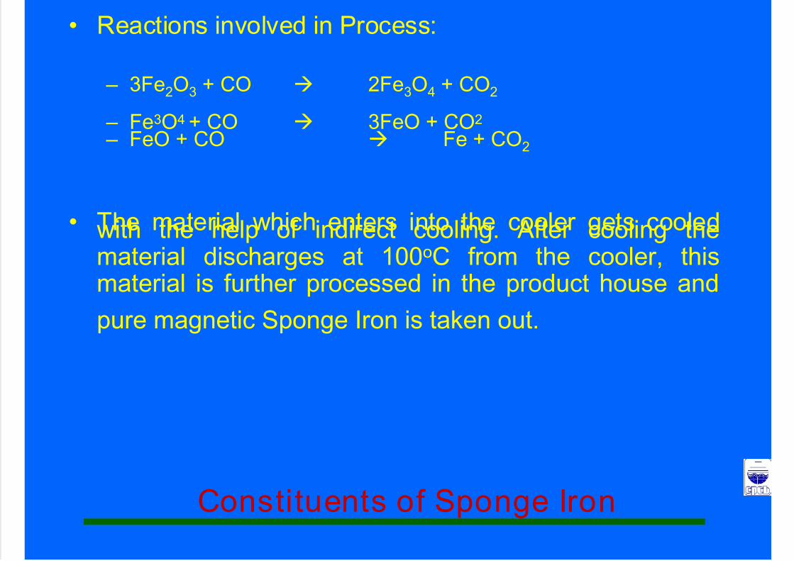
• Reactions involved in Process:
– 3Fe2O3 + CO 2Fe3O4 + CO2
– Fe3O4 + CO 3FeO + CO2
– FeO + CO Fe + CO2
• The material which enters into the cooler gets cooledwith the help of indirect cooling. After cooling thematerial discharges at 100oC from the cooler, thismaterial is further processed in the product house and
pure magnetic Sponge Iron is taken out.
Constituents of Sponge Iron

7/23/2019 Challenges in Iron n Steel by CPCB
http://slidepdf.com/reader/full/challenges-in-iron-n-steel-by-cpcb 73/82
Total Iron (Fe T) – 85 to 90 %
Metallic Iron (Fe M) - 75 to 85 %
Carbon (C) - 0.03 % Sulphur (S) - 0.02 %
Phosphorous (P) - 0.02 %
FeO is calculated from Fe M & Fe T
Metallisation is derived from Fe M & Fe T
Gangue comprising of SiO2, Al2O3, and etc. is Calculated fromthe above given information.
Non – Magnetics.
Effects of various constituents of
Sponge Iron in production of steels

7/23/2019 Challenges in Iron n Steel by CPCB
http://slidepdf.com/reader/full/challenges-in-iron-n-steel-by-cpcb 74/82
• Lower Total Iron – Lower Metallic yield
– Higher Slag generation
– Higher energy consumption
– Higher tap to tap time
• Higher metallic Iron
– Higher metallic yield (steel output)
– Lower FeO content – Lesser slag generation
– Lower energy consumption per unit of steel
produced. – Higher Productivity
Effects of various constituents of
Sponge Iron in production of steels

7/23/2019 Challenges in Iron n Steel by CPCB
http://slidepdf.com/reader/full/challenges-in-iron-n-steel-by-cpcb 75/82
• Higher carbon
– Adequate carbon boil
– Deoxidization
– Reducing FeO
– Higher yield
• Sulphur
– Sulphur in Iron Ore and coal used for theproduction of Sponge Iron is directlyproportional to the Sulphur content in SpongeIron.
– Sulphur is injurious to steel. Therefore,
Sulphur content in Sponge Iron should be aslow as possible.
Effects of various constituents of
Sponge Iron in production of steels

7/23/2019 Challenges in Iron n Steel by CPCB
http://slidepdf.com/reader/full/challenges-in-iron-n-steel-by-cpcb 76/82
• Phosphorous
– Like Sulphur, Phosphorous content in steel should also be low.Iron Ore and coal with low ‘S’ & ‘P’ should be selected for theproduction of Sponge Iron.
• Higher FeO
– Erosion of acid lined refractory
– Lesser lining life – Oxidation of bath
– Higher consumption of Fe alloys
– Higher requirement of carbonaceous material
– Loss of Fe in slag – Excess boiling of the bath
– Higher cost of production
– Restricting usage of other low – grade scrap
Effects of various constituents of
Sponge Iron in production of steels

7/23/2019 Challenges in Iron n Steel by CPCB
http://slidepdf.com/reader/full/challenges-in-iron-n-steel-by-cpcb 77/82
• Metallization
– Metallization is a derived figure, which is a ratio in percentage ofMetallic Iron divided by Total Iron. Higher the metallization,
higher the metallic iron, which results in higher productivity.
• Higher Gangue content
– Delays during melting
– Higher tap to tap time
– Higher energy consumption
– Higher lining erosion
– Lesser yield – Hazardous working
– Lesser productivity
Effects of various constituents of
Sponge Iron in production of steels

7/23/2019 Challenges in Iron n Steel by CPCB
http://slidepdf.com/reader/full/challenges-in-iron-n-steel-by-cpcb 78/82
• Non-Magnetics
– Non – Magnetic comprises mainly of char
material. Char does not have any positive
contribution. It generates slag and reducesthe yield.
7/23/2019 Challenges in Iron n Steel by CPCB
http://slidepdf.com/reader/full/challenges-in-iron-n-steel-by-cpcb 79/82
CLEANER PRODUCTION
TECHNOLOGY OPTIONS
Cleaner Production in Sponge Iron
7/23/2019 Challenges in Iron n Steel by CPCB
http://slidepdf.com/reader/full/challenges-in-iron-n-steel-by-cpcb 80/82
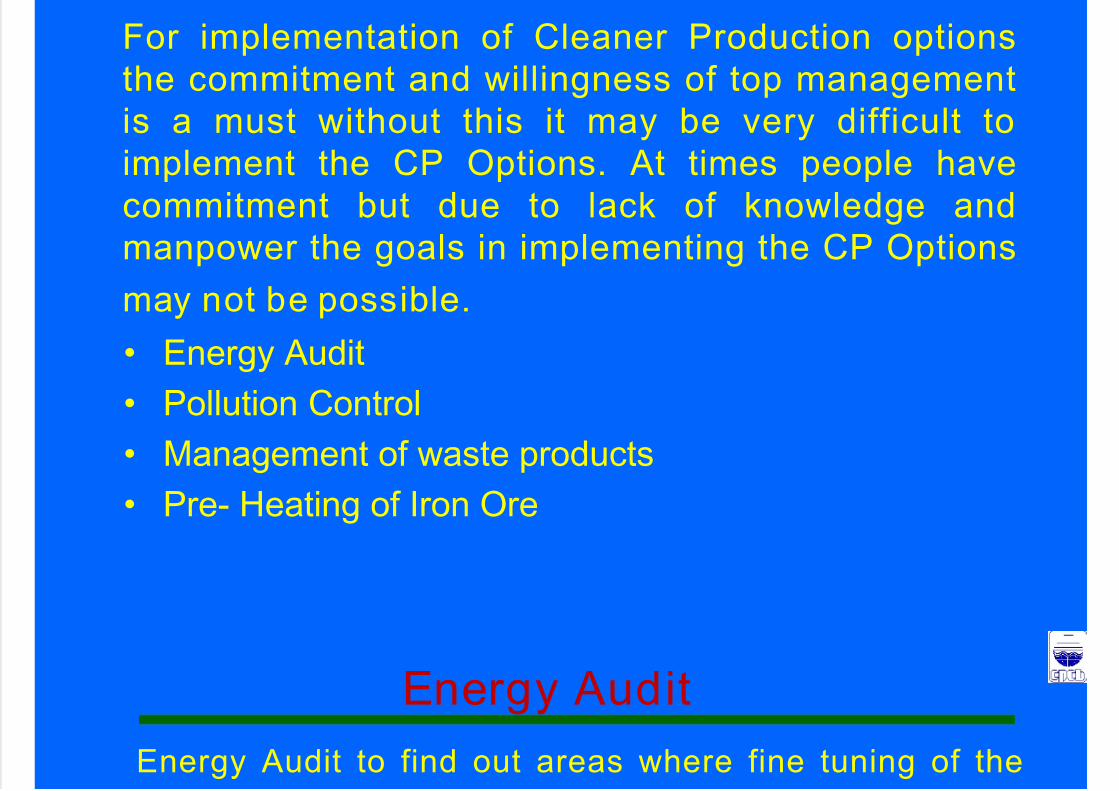
• Energy Audit
• Pollution Control
• Management of waste products
• Pre- Heating of Iron Ore
For implementation of Cleaner Production options
the commitment and willingness of top management
is a must without this it may be very difficult to
implement the CP Options. At times people have
commitment but due to lack of knowledge and
manpower the goals in implementing the CP Options
may not be possible.
Energy Audit to find out areas where fine tuning of the
Energy Audit

7/23/2019 Challenges in Iron n Steel by CPCB
http://slidepdf.com/reader/full/challenges-in-iron-n-steel-by-cpcb 81/82
Voltage (V), Current (C) and Power Factor (PF) arerequired to be carried out.
In Sponge Iron industries, induction motors consume
around 90% of the electricity used. Even a small
increment in the efficiency of these motors can result in
substantial savings which can be possible by adopting
1. System Power Factor should be increased by
connecting proper capacitors
2. Variable frequency drives to be installed
3. Shedding of non-essential loads. Ex:- Lighting, Idle
running of the motors (screen, crusher and product
circuits) and pumps (water circuit)
Pollution Control

7/23/2019 Challenges in Iron n Steel by CPCB
http://slidepdf.com/reader/full/challenges-in-iron-n-steel-by-cpcb 82/82
• Main sources of Air Pollution
– Process
• Installing of control equipments – ESP, GCT,DSC, Bag Filters and Scrubbers.
– Raw Material, Finished Product & WasteProducts