challenges and status on design tsz-ho kwok and
TRANSCRIPT

Yuen-Shan LeungEpstein Department of Industrial
and Systems Engineering,
University of Southern California,
Los Angeles, CA 90089
Tsz-Ho KwokDepartment of Mechanical,
Industrial and Aerospace Engineering,
Concordia University,
Montreal, QC H3G 1M8, Canada
Xiangjia LiEpstein Department of Industrial
and Systems Engineering,
University of Southern California,
Los Angeles, CA 90089
Yang YangEpstein Department of Industrial
and Systems Engineering,
University of Southern California,
Los Angeles, CA 90089
Charlie C. L. WangDepartment of Mechanical
and Automation Engineering,
The Chinese University of Hong Kong,
Shatin, Hong Kong, China
Yong Chen1Epstein Department of Industrial
and Systems Engineering,
University of Southern California,
Los Angeles, CA 90089
Challenges and Status on Designand Computation for EmergingAdditive ManufacturingTechnologiesThe revolution of additive manufacturing (AM) has led to many opportunities in fabricat-ing complex and novel products. The increase of printable materials and the emergenceof novel fabrication processes continuously expand the possibility of engineering systemsin which product components are no longer limited to be single material, single scale, orsingle function. In fact, a paradigm shift is taking place in industry from geometry-centered usage to supporting functional demands. Consequently, engineers are expectedto resolve a wide range of complex and difficult problems related to functional design.Although a higher degree of design freedom beyond geometry has been enabled by AM,there are only very few computational design approaches in this new AM-enabled domainto design objects with tailored properties and functions. The objectives of this reviewpaper are to provide an overview of recent additive manufacturing developments andcurrent computer-aided design methodologies that can be applied to multimaterial, multi-scale, multiform, and multifunctional AM technologies. The difficulties encountered inthe computational design approaches are summarized and the future development needsare emphasized. In the paper, some present applications and future trends related toadditive manufacturing technologies are also discussed. [DOI: 10.1115/1.4041913]
1 Introduction
Additive manufacturing (AM), also known as three-dimensional (3D) printing, has been around for decades. Thetechnology has come on leaps and bounds in the past 10 years,provided an alternative approach to traditional manufacturingprocesses to producing parts. The capabilities of creating complexinternal geometries give engineers more options to innovatewithout being limited by fabrication approaches. Recently, thetechnology has evolved from geometry-focused fabrication intoproducing functional components with varying material composi-tions and geometric scales. Nowadays, fabrication of a multifunc-tional structure is made practical by the next generation of AMtechnologies, enabling advances in products across a wide rangeof applications. However, the increased interdisciplinary interac-tions and the urgent need for practical applications have put for-ward new demands on the design and fabrication of suchmultifunctional structures.
Developing appropriate tools to design a part with functionalconsequences is urgently needed. The existing computer-aideddesign (CAD) software is mainly developed for traditional manu-facturing processes, where geometric shapes are the major con-cern. Although some of the CAD systems allow users to assignmaterial properties on models, the operations cannot guarantee thefunctional capability, especially when the functions can hardly be
realized or optimized by manual design activities. Therefore, mostcurrent research still uses CAD software coupled with finite ele-ment analysis (FEA) and trial-and-error approach to design func-tional properties. Meanwhile, a growing number of researchersbegan developing dedicated computational methods to automatethe design for functionality enabled by AM.
Researchers have extensively studied the topics of changinggeometric shapes to alter an object’s mechanical property. Com-mercial software systems such as OPTISTRUCT [1] have been devel-oped to help designers to create conceptual designs with targetstructural properties. In addition to geometric shapes, researchershave tried to alter material compositions to create even more com-plicated properties. Varying material compositions within layersof 3D printing can now be achieved through controlling processparameters. This additional design freedom offers new and signifi-cant solutions to many industry sectors, such as aerospace [2,3],defense [4], biomedical [5,6], wearable devices [7], and tissueengineering [8].
In additive manufacturing, the internal structure can be opti-mized in multiple scales to satisfy functional requirements.Through optimizing structural parameters, the multiscalestructures can offer multifunctional properties. For example, thewettability of an object is changed from hydrophilic to super-hydrophobic when the surfaces are embedded with micropillars[9]. In addition, a new type of material with microstructures basedon varying unit cells has emerged as an alternative to fulfill com-plex functional demand by using properties that can be dynami-cally programed. Coupling with recent multiscale additivemanufacturing techniques, designing engineering materials uponrequirements is becoming possible.
1Corresponding author.Contributed by the Computers and Information Division of ASME for publication
in the JOURNAL OF COMPUTING AND INFORMATION SCIENCE IN ENGINEERING. Manuscriptreceived May 7, 2018; final manuscript received October 29, 2018; published onlineMarch 18, 2019. Assoc. Editor: Rahul Rai.
Journal of Computing and Information Science in Engineering JUNE 2019, Vol. 19 / 021013-1CopyrightVC 2019 by ASME
Downloaded From: https://computingengineering.asmedigitalcollection.asme.org on 06/21/2019 Terms of Use: http://www.asme.org/about-asme/terms-of-use

Structural property has been the focus of AM since beginning.As the multimaterial and multiscale AM capabilities continue togrow, people began to consider other material properties such asthermal, optical, acoustic, and electrical, as well as how to com-bine them with structural property to create multifunctionalobjects. The additional functionalities add even more challengesto the system designers who are now facing not only interdiscipli-nary problems, but also the unique criteria and characteristics ofdifferent multimaterial and multiscale AM processes. At thismoment, systematic design methodology is required with a betterintegration of design for additive manufacturing methods andtools.
This paper reviews recent research of AM technologies on thefabrication of functional objects and the related design methodolo-gies for AM processes. According to the main design require-ments and constraints, we classify the new capability of AMtechnologies into four categories including
(1) Multimaterial: Design for enhancing mechanical propertiesor material properties (e.g., color) by depositing multipledissimilar materials within one single object (Secs. 2.1and 3.1).
(2) Multiscale: Design for achieving functional requirementsby printing geometric features in multiple geometric scales(Secs. 2.2. and 3.2).
(3) Multiform: Design for programed shape changing propertyafter fabrication (Secs. 2.3 and 3.3).
(4) Multifunctional: Design for objects with non-structuralrequirements. The objects can still have structural proper-ties; however, the main focuses of the studies are on thenonstructural properties (Secs. 2.4 and 3.4).
The purpose of this paper is to give an overview of the currentstatus on functional design for additive manufacturing. We firstsummarize the opportunities enabled by recent AM technologydevelopments in Sec. 2. We then highlight the existing challengesfaced by designers and suggest the best practices and future direc-tions for the research community in Sec. 3. Finally, conclusionsand outlook are drawn in Sec. 4.
2 Recent Development on Additive Manufacturing
Technologies
Additive manufacturing (AM) technologies have been exten-sively developed in the past few decades, with specific techniquesinvented in depositing materials layer upon layer [10]. Comparedwith traditional manufacturing processes, e.g., machining, casting,injection molding, and joining, additive manufacturing is moreflexible in building complex 3D objects in a short period of time[11,12]. Due to its unique advantages, AM technology has beenwidely applied in the fields of aerospace, medical, dental, andsociocultural sectors [13]. This section provides an overview ofrecent developments and current status on AM technologies. Wewill discuss four promising directions for the future developmentof AM technologies, i.e., multimaterial printing, multiscaleprinting, four-dimensional (4D) printing (i.e., 3D printing withtime-variant structures), and multifunctional printing. The discus-sions are mainly based on the process development, the fabrica-tion requirements, and the promising applications of such additivemanufacturing technologies.
2.1 Multimaterial Additive Manufacturing Processes. Avast variety of multimaterials structures and systems withinnovative functions have been developed for applications invarious fields. Some examples include multimaterial compositestructures with shape-changing function, bioinspired multimate-rial composites with promising mechanical performance, multi-material scaffold for tissue regeneration, and multimaterial fiberwith attractive optical applications [14]. Fabrication of novelmultimaterials has become increasingly significant for functional
integration of two or more biological materials. However, tradi-tional manufacturing methods can only provide limited possibilityon fabricating 3D structures with complex spatial distributions ofmultiple materials. In addition, the functional performance of thefabricated structures is limited by the fabrication resolution of thetraditional manufacturing processes. Due to its fabrication capa-bility, additive manufacturing provides a promising solution tofabricate multimaterial structures with high resolution and com-plex geometric shape. Meanwhile, the design of complex struc-tures with multimaterial may also drive the demand fordeveloping even more advanced multimaterial AM processes.
2.1.1 Jetting and Stereolithography Based MultimaterialThree-Dimensional Printing. In most of extrusion-based 3D print-ing processes, thermoplastic is utilized and the state of materialalters from liquid to solid during the extrusion process as a resultof changing thermal conditions [15–17]. Different from thermo-plastic, photo-curable polymer can be solidified with sufficientlight exposure. For instance, based on material jetting technolo-gies, 3D multimaterial inkjet printing is developed to fabricatecomplicated structures using photopolymer and wax. Microscaledroplets of photo curable ink are deposited layer by layer in theinkjet printing process, and droplets can be turned to solid afterreceiving enough energy from light exposure [4,18,19]. Due to thehigh resolution of mature jetting technology, the surface qualityof objects printed by polyjet/inkjet printing is much better thanthe one built by the fused deposition modeling (FDM) process. Inaddition, high-resolution multimaterial 3D printing opens up anew future to the optical application. Bio-mimic imaging opticaleye and display window, which is not easy to be fabricated usingtraditional methods, were fabricated by the inkjet-based 3D print-ing using transparent acrylic polymer [20]. The jetting-based mul-timaterial 3D printing can also achieve superior mechanicalperformance that cannot be provided by single material printing.Biological structures found in nature give one inspirations thatsoft and hard materials can be allocated in a distributed pattern toachieve certain mechanical performance. Multimaterial 3D print-ing processes enable the improvement of structural propertieswith special design of material distribution. Gu et al. [4] used anObjet 500 3D printer to replicate the innate toughness of the nacreand a conch shell. In the nacre-like designs, two base materials,which are vastly different in properties, were assembled in a plywith an architecture similar to nacre. These plies were thenstacked with orientation angles of 0 and 90 deg to generate a lami-nate structure by multimaterial 3D printing (Fig. 1(c)). Similarly,prototypes of mixing stiff plate and soft matrix of bone-like plate,mollusk shells shaped structures, and ganoid fish scales were fab-ricated by the inkjet printing process, and the printed part demon-strates promising mechanical performance [19].
Stereolithography (SL) is another 3D printing process by usingphoto-curable polymer to build 3D objects. Instead of curingdroplets, one layer of photo curable polymer can be solidified bythe exposure of the two-dimensional (2D) patterned light beam inthe mask-image-projection-based stereolithography (MIP-SL)[21]. Compared with other AM methods, the building speed ofMIP-SL process is relatively fast by taking advantages of high-resolution 2D patterned light beam. Therefore, numerous studiesare conducted to develop MIP-SL based multimaterial processes[22–25]. With the special design of the layouts of different materi-als, the structure can be controlled to bend or twist under differentenvironmental situations. Using multimaterial 3D printing techni-ques, such as inkjet or SL processes, shape-changing anisotropycan be achieved by combining a responsive shape-changing mate-rial with a passive matrix material [23]. Similarly, the thermal per-formance of 3D printed parts can be manipulated by materialallocation. As shown in Fig. 1(d), negative thermal explosionmicro lightweight multimaterial lattice structures were printed bymask-image projection-based SL printing process, with differentmixture ratios of photo-curable polymer and copper nanoparticlessolutions [22]. According to the fabrication requirements, new
021013-2 / Vol. 19, JUNE 2019 Transactions of the ASME
Downloaded From: https://computingengineering.asmedigitalcollection.asme.org on 06/21/2019 Terms of Use: http://www.asme.org/about-asme/terms-of-use

material is easy to be added in the SL-based system by increasingthe number of material reservoirs. Current multimaterial MIP-SLprocess is rather slow, since the residual material removal is man-datory prior to the placement of new material. Due to insufficientremoval force as well as adhesive forces between resin moleculesand a cured part, incoming new material tends to mix with theresidual and generate blur mixtures attached to the cured part.Such blur mixtures existing in the interface area of different mate-rials usually affect the performance of fabricated objects and isstill a challenge for researchers to overcome in the future.
2.1.2 Extrusion Based and Other Multimaterial Three-Dimensional Printing Methods. Unlike subtractive manufacturingprocesses, raw material is gradually deposited in AM processes tobuild an object from scratch. Based on the deposition principle,multimaterial 3D objects can be constructed by using multiplematerial supplies. For example, multimaterial FDM process hasbeen developed in which different materials are extruded fromdifferent extruders [16]. Based on the material extrusion method,a broad variety of material such as thermoplastics, ceramic slur-ries, and metal pastes can be printed using the FDM process.Moreover, structures with a lot of overhangs can be easily printedusing a multimaterial FDM machine with dissolvable supportingmaterial. However, this inexpensive multimaterial AM solution islimited by poor fabrication resolution due to the dimension ofextruders [26–28]. To get better fabrication resolution, anotherkind of 3D printing method using specially designed printheadshas been developed to fabricate multimaterial structures[15,17,29]. One kind of such printheads that consist of a bundle ofcapillaries in connection with multiple printing-ink reservoirs wasdesigned to continuously actuate digital material under controlla-ble pneumatic pressure, as shown in Fig. 1(b). Cells, culturematrix, and growth factor were continuously extruded togetherinto specially designed organ structures, and the biomaterials keptbioactivities during the extrusion process. Multimaterial 3D struc-tures show multiple functional performances because each type ofmaterial can have unique physical properties. Multimaterial 3Dprinting process enables the fabrication of active functional struc-tures with multiple materials to achieve interesting applications.Traditionally, single material, such as plastic polymer, conductors,and biological material, can be easily printed using the extrusion-based process. Five different types of materials, including semi-conducting nanoparticles, elastomer, organic polymer, solid andliquid metal, and ultraviolet curable polymer, are integrated
together by the extrusion-based process to build a functional quan-tum dot light-emitting diode (Fig. 1(a)) [15]. The extrusion-basedmultimaterials 3D printing process offers the capability of highlyflexible fabrication, and the capability of directly depositing mul-tiple functional materials enables one to build a semiconductingelectronic device with complex geometric shapes. In addition tothe aforementioned processes, which are mainly developed to fab-ricate liquid-based materials, researchers have developed variouspowder-based multimaterial printing processes. For example, thebinder jetting 3D printing method was developed to fabricatemulti-material structures using various powders including poly-mer powders, ceramic powders, and metal powders [30].
2.2 Multiscale Additive Manufacturing Processes. Withincreasing biomimetic research on the design of multiscale struc-tures for different functions, the fabrication of novel multiscalestructures has become increasingly important. The developmentof multiscale additive manufacturing processes is desired and crit-ical to achieve such biomimetic designs for certain functionality.However, most of the existing AM technologies can only fabricate3D structures with a uniform resolution throughout the entire fab-rication process. However, a large amount of functional structurescontains both micro- and/or nanoscale features on macroscale sub-tract, such as shark skin, peristome surface of Nepenthes alata,gecko feet, fly eyes, and butterfly wing [31]. It is difficult for theexisting manufacturing processes to fabricate such complex geo-metric shape, and the functional performance of the built artificialbiomimetic objects cannot be comparable with respect to theirgenuine counterparts in nature. Therefore, the development ofmultiscale AM processes attracts much attention in recent years.There are two main representative ideas that have been investi-gated. One solution is to fabricate multi-scale structures by theintegration of multiple AM processes, each of which best suits acertain scale. This method can make multiple sections of a struc-ture by applying optimized processes [32–34], and a designedhybrid process can provide capability and flexibility superior thanoperating each of the individual printing processes separately.However, the integrated hybrid solution can only adapt to buildingmultiscale objects with a special design; how to integrate different3D printing processes to fabricate 3D objects with any universaldesign still remains a significant challenge. Another solution thathas been investigated is the development of standalone 3D print-ing process that is capable to achieve multiscale fabrication on itsown.
Fig. 1 (a) Direct 3D printing of QD-LEDs on a substrate [15] (Reprinted with permission from American Chemical Society #
2014). (b) Design of a digitally tunable continuous multimaterial extrusion bio-printer and the side view of selected organ-likeconstructs [21] (Reprinted with permission of John Wiley and Sons # 2016). (c) 3D-printed nacre-inspired sample and quartergeometry of the Nacre-like design in simulation [4] (Reprinted with permission of John Wiley and Sons # 2017). (d) Three-dimensional fabricated negative thermal expansion lattice structures using multimaterial projection microstereolithographysystem [22] (Reprinted with permission from American Physical Society# 2018).
Journal of Computing and Information Science in Engineering JUNE 2019, Vol. 19 / 021013-3
Downloaded From: https://computingengineering.asmedigitalcollection.asme.org on 06/21/2019 Terms of Use: http://www.asme.org/about-asme/terms-of-use

2.2.1 Stereolithography-Based Multiscale Three-DimensionalPrinting. To generate smooth and uniform microscale structures,liquid-based material deposition needs to be highly accurate thusrequires high-precision motion control of printing nozzles withextremely small openings. In contrast, SL process can fabricatehigh-resolution microfeatures using controlled light exposure[35,36]. However, the size of macroscale focus image, which inturn determines the fabrication range, is restricted to the physicaldimension of the digital micromirror device (DMD) chip, andsuch an issue is open to be resolved for the purpose of multiscalefabrication using the SL process [33]. One straightforward solu-tion is to jointly use multiple DMD chips to shape a larger array;however, the uniformity of projection light with multiple DMDchips working at the same time becomes difficult to control. Otherthan the simple combining approach, a hybrid process could alsobe a potential solution to address the multiscale fabrication prob-lem. For example, a swirling flow coaxial phacoemulsifier sleevewith internal microvanes were fabricated by combining multijetmodeling (3DP) and mask image projection based microstereoli-thography (PlSL) [32]. Besides, some multi-scale structures,whose dimension ranges from macro-scale to nano-scale, werefabricated by the integration of SL process and the two photopolymerization process [33]. Alternatively, for the mask imageprojection based SL process, researchers also achieved multiscalefabrication by adding movement of the projection light beam. Forexample, Emami et al. [37] extended the fabrication area of theMIP-based SL process by moving the optical system only one-pixel length each step, illuminating one portion with several timeexposure. The known issue for this method is that overlaps existbetween two adjoining printed sections [37,38]. To eliminate theoverlap, Lee et al. [39] developed a low-cost scanning projectionprinting system, which can project microscale features at 10 lmonto a 50mm large area by precisely controlling the exposure time.
Meanwhile, laser spot with dynamic changing focus can also beused to print multiscale structures [40]. For a given multiscale struc-tures, the appropriate laser spot can be selected to cure correspond-ing sizes of features, respectively. Similarly, the laser can beadjusted by an optical filter with high-contrast gratings to accommo-date features at different scales, similar to the principle of nanoli-thography technology [41]. However, it is time-consuming tofabricate objects with large area using the nano-scale laser beam. Tosolve the fabrication efficiency problem, Mao et al. [42] developedan optimized multiscale fabrication process with shaped beams, andthe 3D printing speed and resolution were significantly improved.The developed process planning associated with the shaped beammethod is shown in Fig. 2(f). The SL-based multiscale process isalso applied to fabricate cases that are either hard to be imple-mented or even impossible before. For example, multicomponentobjective lenses mimicking the eagle eye were designed andprinted onto a complementary metal-oxide semiconductor imagesensor using a revised SL process [45]. This artificial optical sys-tem shown in Fig. 2(g) can achieve a full field of view of 70 deg,with the angular resolution up to 2 cycles/deg in the center of theimage [45,46]. Besides, micro- and nano-optics with complexartificial eye lens was fabricated by a novel microscale 3D printmethod called femtosecond two-photon direct laser writing. Theprinted microlens at 100 lm forms a high-performance multilenswith the field of view at 80 deg.
2.2.2 Other Multi-Scale Three-Dimensional PrintingMethods. Multi-scale fabrication can be implemented by using 3Dprinting with nozzles in different sizes. As shown in Figs. 1(a)and 1(b) and Figs. 2(a) and 2(b), large scale structures with micro-scale features were successfully fabricated by the method of directink writing, where the fabrication resolution can be controlled bymultiple process parameters, such as the moving speed of the
Fig. 2 (a) Omnidirectional printing of 3D microvascular networks within a hydrogel reservoir [43] (Reprinted with permissionof John Wiley and Sons # 2011). (b) 3D-printed multiscale spider web displaying interacting radial and spiral elastomericfilaments [44] (Attribution 4.0 International CC BY 4.0). (c) 3D-printed multiscale biomimetic artificial skin [45] (Reprinted withpermission of Company of Biologists Ltd., # 2014). (d) Bio-inspired vapor-responsive colloidal photonic crystal patterns bymultiscale inkjet printing [46] (Reprinted with permission from American Chemical Society# 2014). (e) The multiscale printingbased on scanning projection stereolithography and the 3D-printed lattice structures [39]. (f) A schematic diagram ofmultiscale fabrication process. The multiscales in the XY-plane are achieved by using laser beams in different sizes, and themultiscales along the Z-axis are realized by using different layer thicknesses [42]. (g) 3D-printed eagle eye: compound micro-lens system for foveated imaging [47].
021013-4 / Vol. 19, JUNE 2019 Transactions of the ASME
Downloaded From: https://computingengineering.asmedigitalcollection.asme.org on 06/21/2019 Terms of Use: http://www.asme.org/about-asme/terms-of-use
nozzle, the material feeding speed, and the dimension of nozzle[43,47–52]. Similarly, a new direct ink writing method was devel-oped to fabricate multiscale biologic structures, e.g., microvascu-lar network. In the process shown in Fig. 2(a), hydrogel wasinjected into the gel tank according to the 3D geometry of vascu-lar structures, followed by the forming of vessel cavity as injectedhydrogel turned to be liquid when temperature changes [43]. Inaddition, multi-scale complex fluidic networks were printed ingranular gel slurry using the nozzle-based 3D printing [48]. Afterremoving granular gel from the printed structures, multiscale hier-archical branching networks were easily generated with thedimension range from 100 lm to 10mm. Recently, a nozzle-based 3D printing process was applied to fabricate a multiscalebiomimetic, spiders spin that possesses high strength, elasticity,and tensile failure stress at the same time. As shown in Fig. 2(b),the mechanical response of elastomeric webs was investigatedunder multiple loading conditions, and the study results showpromising characteristics of the webs’ performance [44].
Recent progresses on multiscale AM technologies have facili-tated the performance study of multi-scale structures such assuperhydrophobicity, self-cleaning, drag reduction, energy con-version, biological self-assembly, and focusing imaging [53]. Asan example, special placoid scales associated with the surface ofshark skin have intriguing properties to dramatically reduce fric-tional fluid drag. While it is difficult to use traditional manufactur-ing processes to fabricate such placoid scales, they have beensuccessfully built onto the artificial shark skin by the nozzle-based3D printing methods (refer to Fig. 2(c)), and such multiscale sharkskin presented excellent flow ability compared with the surfacewithout any microfeatures [54]. Also, the multiscale nozzle-based
3D printing process provides a great promise to developingadvanced optical elements, such as dynamic display or multifunc-tional sensor array. For example, the multicolor shifting van wasprinted with multiscale colloidal photonic crystals patterns usingmesoporous colloidal nanoparticle ink, as shown in Fig. 2(d).Through adjustment on the size and mesoporous proportion ofnanoparticles, original color and vapor-responsive color shift wereprecisely and easily controlled [55]. While 3D printing is beingintroduced to more applications of biology, tissue engineering,autonomous vision, and optical systems, the development of mul-tiscale 3D printing continues to attract increasing interest fromresearchers and industry professionals.
2.3 Shape Changing Additive Manufacturing Processes.Tibbits [56,57] used a term four-dimensional (4D) printing todescribe a class of 3D printing technologies applied to buildingshape-changing structures (see Fig. 3(a)). 4D printing overcomes thetraditional fabrication limitations by designing heterogeneous materi-als to enable the 3D-printed structures evolving over time (the fourthdimension) [58–63]. There are many different ways to generate thetime-variant structural change using 3D printing processes. Somecommon 4D printing approaches are listed in the section.
2.3.1 Thermal Stimuli. One way to build shape changingstructures is to use multimaterial 3D printing processes with theintegration of additional thermal stimuli [24,64,65]. Basic shape-changing materials available for these multimaterial 3D printingtechniques include shape-memory polymer (SMP) [66] and hydro-gel [67]. Additionally, elastomers are typically used as the passivematrix in these structures. Ge et al. [58] printed active composite
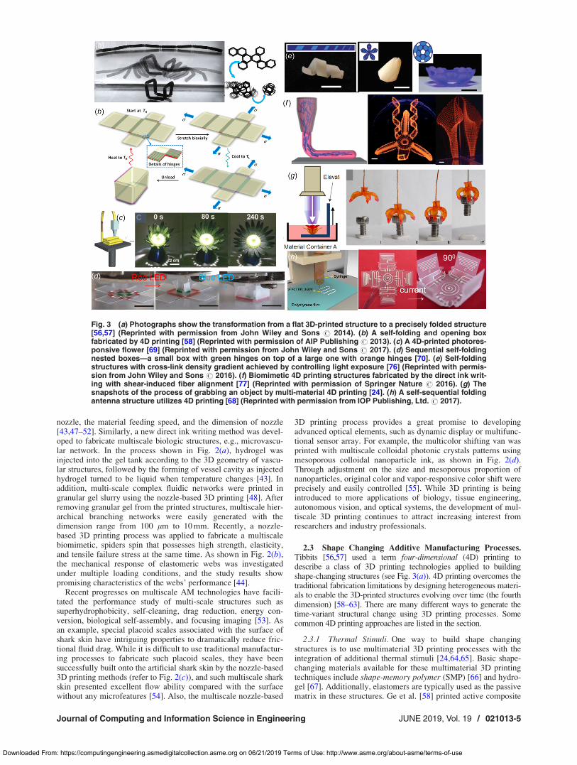
Fig. 3 (a) Photographs show the transformation from a flat 3D-printed structure to a precisely folded structure[56,57] (Reprinted with permission from John Wiley and Sons # 2014). (b) A self-folding and opening boxfabricated by 4D printing [58] (Reprinted with permission of AIP Publishing # 2013). (c) A 4D-printed photores-ponsive flower [69] (Reprinted with permission from John Wiley and Sons # 2017). (d) Sequential self-foldingnested boxes—a small box with green hinges on top of a large one with orange hinges [70]. (e) Self-foldingstructures with cross-link density gradient achieved by controlling light exposure [76] (Reprinted with permis-sion from John Wiley and Sons # 2016). (f) Biomimetic 4D printing structures fabricated by the direct ink writ-ing with shear-induced fiber alignment [77] (Reprinted with permission of Springer Nature # 2016). (g) Thesnapshots of the process of grabbing an object by multi-material 4D printing [24]. (h) A self-sequential foldingantenna structure utilizes 4D printing [68] (Reprinted with permission from IOP Publishing, Ltd.# 2017).
Journal of Computing and Information Science in Engineering JUNE 2019, Vol. 19 / 021013-5
Downloaded From: https://computingengineering.asmedigitalcollection.asme.org on 06/21/2019 Terms of Use: http://www.asme.org/about-asme/terms-of-use

materials that were realized by directly printing glassy SMP fibersin an elastomeric matrix (see Fig. 3(b)). The initial configurationis created by 3D printing, and then the programmed action ofthese shape memory fibers creates the time dependence of shapechanging configurations (i.e., the 4D aspect). The 3D-printedstructure can be thermomechanically programmed to assume com-plex four-dimensional configurations, including bent, coiled, andtwisted strips, folded shapes, and complex contoured shapes withnonuniform, spatially varying curvature. More interestingly,incorporating more than one shape-changing material with differ-ent responsive properties enables sequential shape changes via thesame multimaterial 3D printing techniques. For example, whenmultiple SMPs with different thermomechanical properties wereincorporated, sequential shape changes that are time-dependentcan be accomplished by changing the triggering temperatures, asshown in Fig. 3(g) [24]. A 3D-printed gripper was opened (orclosed) after applying appropriate thermal stimuli and the func-tionality of grabbing (or releasing) objects was triggered. Denget al. [68] further present the 4D printing of self-folding structuresthat can be sequentially and accurately folded using heating pro-vided by electric circuit (Fig. 3(h)). When being heated abovetheir glass transition temperature, prestrained polystyrene filmsshrink along the XY plane. Accordingly, silver ink traces printedon the film were used to provide heat stimuli by conducting cur-rent to trigger the sequential self-folding behaviors. Some pro-grammable structures such as a lock and a three-dimensionalantenna were demonstrated to illustrate the feasibility and poten-tial applications of this method.
2.3.2 Light Stimuli. Light stimuli have also been used to buildshape changing structures. Yang et al. [69] demonstrated the 3Dprinting of photoresponsive shape memory devices throughcombining the FDM process and photoresponsive shape memorypolymers/carbon black composites (see Fig. 3(c)). A biomimeticsunflower is built to demonstrate its shape changing functionunder sunlight. Furthermore, Liu et al. [70] created a sequentialfolding structure by different colors of light sources (seeFig. 3(d)). Controlled ink printed on the surface of polymer sheetscan discriminately absorb light on the basis of the wavelength andthe color of the ink defines the hinge about which the sheet wouldfold. The absorbed light gradually heats the underlying polymeracross the thickness of the sheet, which causes relief of strain toinduce folding. These color patterns can be designed to absorbonly specific wavelengths of light, thereby providing control ofsheet folding with respect to time and space. This type of pro-gramed shape variation can have numerous applications, includingreconfigurable electronics, actuators, sensors, implantable devices,smart packaging, and deployable structures.
2.3.3 Moisture Stimuli. The anisotropy in a 3D-printedstructure is the key that is used to trigger shape changing. Anotherpopular stimulus for 4D printing is provided by moisture. Themechanical anisotropy that comes from bio-inspiration can berealized by various methods including magnetic alignment andshear force alignment of fillers [71–75]. The cross-linking densitygradient in polymers can be achieved by tuning the processparameters during the selected fabrication process, such as thelight dose exposure in stereolithography, or the heating tempera-ture and the moving speed of the nozzle used in FDM [76]. Theshrinkage is constrained by the building platform during the fabri-cation process, yielding a strain gradient within the 3D-printedstructures (as shown in Fig. 3(e)). Heating the final structuresreleases the built-in strain and accordingly results in desiredshape-changing behaviors. Shear-induced alignment has been suc-cessfully used in a direct ink writing process to attain localizedswelling anisotropy in swellable shape-changing structures, asdepicted in Fig. 3(f) [77]. The alignment of stiff cellulose fibrils inhydrogels was controlled by the prescribed printing paths, and theextent of the alignment can be adjusted by the nozzle diameterand the printing speed. After being cured by ultraviolet light, a
3D-printed structure was immersed in de-ionized water to initiatethe swelling-related shape changes. Compared with the traditionalsubtractive manufacturing processes to fabricate fiber-basedhydrogel composites [78], the 3D printing technique offersincreased flexibility in controlling the local alignment of fibersduring the fabrication process, which enables the shape-changingstructures to have more complex behaviors.
Overall, various shape-changing structures can be achieved via3D printing responsive and deformable materials in an architecturewith anisotropic material properties. The responsive and deforma-ble materials can exhibit simple shape changes, such as shrinkageor expansion, upon exposure to external stimuli including moisture,heat or light, and a structure with both responsive and passive mate-rials can achieve more complex shape changing configurations.
2.4 Multifunctional Additive Manufacturing Processes.Additive manufacturing processes have been used to buildmultifunctional structures, e.g., multifunctional flexible sensors[79–83], electronics [84,85], and hydrodynamic structures [86].Due to the advantage of being able to fabricate objects complexgeometric shapes, AM technologies have already been used tofabricate devices with enhanced functionality or performance.Among a wide range of research on various functions beyondstructural property, we selected one or two representative workfor some common functions and discussed them in the section.
2.4.1 Sensing Property. A multimaterial and multiscale 3Dprinting approach has been employed under ambient conditions tofabricate 3D tactile sensors that conform to freeform surfaces [87].The customized sensor is demonstrated with the capabilities ofdetecting and differentiating human movements, including pulsemonitoring and finger motions. The 3D-printed tactile sensor con-sisting of a base layer (silicon), top and bottom electrodes (with75% Ag/silicon), an isolating layer, a sensor layer (with 68% Ag/silicon), and a supporting layer (see Fig. 4(a)). The 3D-printed flex-ible, stretchable, and sensitive sensors were found to be capable ofdetecting and differentiating human movements, including radialpulse, finger pressing, and bending [88]. Development of a custom-built multifunctional 3D printing process, combined with functionalinks, is at the core of this approach and determines the functionalfeatures of final devices. A real-time monitoring system of bodymotion was designed by using smart phones and 3D-printed cal-cium-silicate-hydrate hydrogel. The autonomous intrinsic self-healing of hydrogel is attained through dynamic ionic interactionsbetween carboxylic groups of poly(acrylic acid) and ferric ions(Fig. 4(b)). Establishing a fair balance between the chemical andphysical cross-linking networks together with the conductive nano-structure of polypyrrole networks leads to a double network hydro-gel with bulk conductivity, mechanical and electrical self-healingproperties (100% mechanical recovery in 2 min), ultrastretchability(1500%), and pressure sensitivity.
2.4.2 Thermal Property. Yao et al. [89] developed 3D-printedreduced graphene oxide (RGO)-based heaters to function as high-performance thermal supply with high electrical conductivity, hightemperature, and ultrafast heating rate. Joule heating was used toeffectively reduce RGO at high temperature (Fig. 4(c)). The 3D-printed heater with RGO flakes can reach a high heating tempera-ture, up to 3000 K. The heater temperature can be ramped up anddown with extremely fast rates (i.e., up to about 20,000 K/s). The3D printable RGO heaters with different shapes can be applied to awide range of nanomanufacturing when precise temperature controlin time, position, and the ramping rate is important.
2.4.3 Hydrodynamic Property. Superhydrophobic microstruc-ture inspired by Salvinia molesta [9] was fabricated by theimmersed surface accumulation 3D printing process. The multi-scale artificial hairs with eggbeater heads were reproduced accord-ing to the eggbeater structure design in nature. The head isfabricated by intersecting different numbers of circumferences witha diameter of 35 lm and a height of 250 lm (Fig. 4(d)). The
021013-6 / Vol. 19, JUNE 2019 Transactions of the ASME
Downloaded From: https://computingengineering.asmedigitalcollection.asme.org on 06/21/2019 Terms of Use: http://www.asme.org/about-asme/terms-of-use
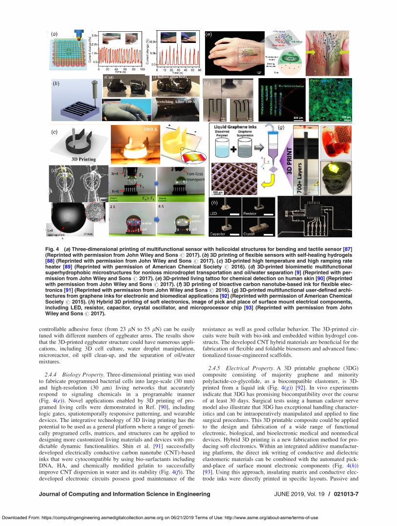
controllable adhesive force (from 23 lN to 55 lN) can be easilytuned with different numbers of eggbeater arms. The results showthat the 3D-printed eggbeater structure could have numerous appli-cations, including 3D cell culture, water droplet manipulation,microreactor, oil spill clean-up, and the separation of oil/watermixtures.
2.4.4 Biology Property. Three-dimensional printing was usedto fabricate programmed bacterial cells into large-scale (30 mm)and high-resolution (30 lm) living networks that accuratelyrespond to signaling chemicals in a programable manner(Fig. 4(e)). Novel applications enabled by 3D printing of pro-gramed living cells were demonstrated in Ref. [90], includinglogic gates, spatiotemporally responsive patterning, and wearabledevices. The integrative technology of 3D living printing has thepotential to be used as a general platform where a range of geneti-cally programed cells, matrices, and structures can be applied todesigning more customized living materials and devices with pre-dictable dynamic functionalities. Shin et al. [91] successfullydeveloped electrically conductive carbon nanotube (CNT)-basedinks that were cytocompatible by using bio-surfactants includingDNA, HA, and chemically modified gelatin to successfullyimprove CNT dispersion in water and its stability (Fig. 4(f)). Thedeveloped electronic circuits possess good maintenance of the
resistance as well as good cellular behavior. The 3D-printed cir-cuits were built with bio-ink and embedded within hydrogel con-structs. The developed CNT hybrid materials are beneficial for thefabrication of flexible and foldable biosensors and advanced func-tionalized tissue-engineered scaffolds.
2.4.5 Electrical Property. A 3D printable graphene (3DG)composite consisting of majority graphene and minoritypolylactide-co-glycolide, as a biocompatible elastomer, is 3D-printed from a liquid ink (Fig. 4(g)) [92]. In vivo experimentsindicate that 3DG has promising biocompatibility over the courseof at least 30 days. Surgical tests using a human cadaver nervemodel also illustrate that 3DG has exceptional handling character-istics and can be intraoperatively manipulated and applied to finesurgical procedures. This 3D printable composite could be appliedto the design and fabrication of a wide range of functionalelectronic, biological, and bioelectronic medical and nonmedicaldevices. Hybrid 3D printing is a new fabrication method for pro-ducing soft electronics. Within an integrated additive manufactur-ing platform, the direct ink writing of conductive and dielectricelastomeric materials can be combined with the automated pick-and-place of surface mount electronic components (Fig. 4(h))[93]. Using this approach, insulating matrix and conductive elec-trode inks were directly printed in specific layouts. Passive and
Fig. 4 (a) Three-dimensional printing of multifunctional sensor with helicoidal structures for bending and tactile sensor [87](Reprinted with permission from John Wiley and Sons # 2017). (b) 3D printing of flexible sensors with self-healing hydrogels[88] (Reprinted with permission from John Wiley and Sons # 2017). (c) 3D-printed high temperature and high ramping rateheater [89] (Reprinted with permission of American Chemical Society # 2016). (d) 3D-printed biomimetic multifunctionalsuperhydrophobic microstructures for nonloss microdroplet transportation and oil/water separation [9] (Reprinted with per-mission from John Wiley and Sons # 2017). (e) 3D-printed living tattoo for chemical detection on human skin [90] (Reprintedwith permission from John Wiley and Sons # 2017). (f) 3D printing of bioactive carbon nanotube-based ink for flexible elec-tronics [91] (Reprinted with permission from John Wiley and Sons # 2016). (g) 3D-printed multifunctional user-defined archi-tectures from graphene inks for electronic and biomedical applications [92] (Reprinted with permission of American ChemicalSociety # 2015). (h) Hybrid 3D printing of soft electronics, image of pick and place of surface mount electrical components,including LED, resistor, capacitor, crystal oscillator, and microprocessor chip [93] (Reprinted with permission from JohnWiley and Sons# 2017).
Journal of Computing and Information Science in Engineering JUNE 2019, Vol. 19 / 021013-7
Downloaded From: https://computingengineering.asmedigitalcollection.asme.org on 06/21/2019 Terms of Use: http://www.asme.org/about-asme/terms-of-use
active electrical components were then integrated to produce thedesired electronic circuitry by using an empty nozzle (in vacuum-on mode) to pick up individual components, place them onto thesubstrate, and then deposit them (in vacuum-off mode) in thedesired location. The components are then interconnected via 3D-printed conductive traces to yield soft electronic devices that mayfind potential application in wearable electronics, soft robotics,and biomedical devices.
The growing maturity of multimaterial and multiscale 3D print-ing capabilities enabled different industries to develop new prod-ucts that are tailor-made, high performance, and multifunctional.We will see a much more radical change in the way that productsare designed and manufactured. At the same time, the needs forstandardized and automated design process are becoming critical,and the related design computation methods are one of the mostessential components of design for additive manufacturing.
3 Recent Development on Design for Additive
Manufacturing Technologies
Additive manufacturing processes always start from a three-dimensional solid model that specifies the necessary informationin order for AM to fabricate the exact shape. Usually, only geome-try is provided in a digital CAD file, which is converted into 2Dlayers by a slicing software system. The 2D layers hereby depictthe contour of the digital model and can facilitate the layer-by-layer printing processes. For decades, researchers have conductedstudies on how to do process planning to enhance the quality offabricating results [13].
Recently, with the emergence of new 3D printing processes, a par-adigm shift has occurred in the additive manufacturing field fromgeometry-centered fabrication to supporting more functional require-ments. This shift is changing the design methodology from singlerequirements to catering solutions for more demanding requirementssuch as fabricating heterogeneous objects with enhanced mechanicalproperties. In addition to geometric shapes, additional informationlike material compositions is required to be computed in the designstage. In this section, the current design methodologies are reviewedwith the challenges for each type of AM processes discussed.
3.1 Design for Multimaterial Additive ManufacturingProcesses. Multi-material object often refers to the class ofobjects that have different material compositions with a single
object. Although the state-of-the-art CAD software systems arecapable of defining discrete multimaterial regions, the variety offunctional requirements, engineering materials, and AM processesstill makes the formulation of a standard pipeline challenging.Most of the CAD software systems only focus on how to assignmaterials, such as through geometric operations [94], yet lack theability to design where to place materials to achieve demandedfunctional properties. Sections 3.1.1–3.1.3 will explore a varietyof design methodologies developed for heterogeneous objects,specifically about enhancing structural and other material proper-ties by fabricating the heterogeneous objects through multimate-rial AM processes.
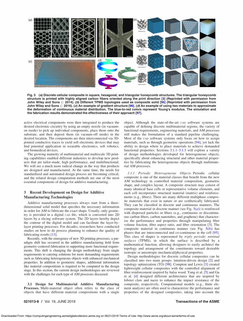
3.1.1 Periodic Heterogeneous Objects. Periodic cellularcomposite is one of the material classes that benefit from the newAM technology in controlled material composition, geometricshape, and complex layout. A composite structure may consist ofmany identical base cells or representative volume elements, andeach cell incorporates structural material (matrix) and reinforce-ments (e.g., fibers). There are many different multiphase compos-ite materials that exist in nature or are synthetically fabricated.They can be classified in discrete and continuous manners. Thecomposite material in discrete manner (see Fig. 5(a)) is reinforcedwith dispersed particles or fibers (e.g., continuous or discontinu-ous carbon fibers, carbon nanotubes, and graphene) that character-ize the performance and properties through manipulating fibervolume fraction, fiber aspect ratio, and fiber orientation [3]. Thecomposite material in continuous manner (see Fig. 5(b)) hasphases that are interconnected and co-continuous in the cell [95].This class of shapes is represented by triply periodic minimalsurfaces (TPMS), in which the surface is described by amathematical function, allowing designers to easily architect thetopology and arrangement of the constituents toward desirableisotropic or anisotropic mechanical/physical properties.
Design methodologies for discrete cellular composites can beclassified into two main groups: intuition-driven design [2] andtopology optimization (TO) [98]. Compton and Lewis [3] createdlightweight cellular composites with the controlled alignment offiber reinforcement inspired by balsa wood. Yang et al. [5] and Guet al. [4] designed different architectures that are inspired bylobster claw and nacre to enhance the impact resistance of thecomposite, respectively. Computational models (e.g., finite ele-ment analysis) are often used to characterize the performance andproperties of the designed composites, taking into account the
Fig. 5 (a) Discrete cellular composite in square, hexagonal, and triangular honeycomb structures. The triangular honeycombstructure is printed with highly aligned carbon fibers oriented along the print direction [3] (Reprinted with permission fromJohn Wiley and Sons # 2014). (b) Different TPMS topologies used as composite solid [95] (Reprinted with permission fromJohn Wiley and Sons # 2016). (c) An example of gradient structure [96]. (d) An example of using two materials to approximatethe deformation of continuous material distribution. The blue-to-red colors represent Young’s modulus. The simulation andthe fabrication results demonstrated the effectiveness of their approach [97].
021013-8 / Vol. 19, JUNE 2019 Transactions of the ASME
Downloaded From: https://computingengineering.asmedigitalcollection.asme.org on 06/21/2019 Terms of Use: http://www.asme.org/about-asme/terms-of-use

materials’ properties [99]. Hu et al. [2] proposed to randomly dis-tribute the reinforcement to extract the composites’ properties.Quan et al. [100] reviewed other design models of reinforcementfor cellular composite, such as woven fabric and braided preforms.With computational modeling and simulation, high-performancedesign would be possible after optimization. However, when thefabrication of composites involves several groups of intertwiningyarns such as textile assemblies, the computational cost on theexisting CAD design tools could be extremely high. To obtain theoptimized design of cellular materials, some recent works havefocused on topology optimization. For instance, Long et al. [101]proposed a concurrent optimization for composites composed ofphases with distinct Poisson’s ratios. Their approach optimized thecomposite unit cells and their distribution in macrostructures simul-taneously. Nevertheless, new frontier AM technologies keepincreasing the printing dimension of the objects, and concurrently,the available printing resolution becomes increasingly finer. As aresult, the computational effort rapidly becomes prohibitive.
Another composite material, periodic interpenetrating phasecomposites, has recently caught attention due to its smooth-curved nature of the TPMS surfaces, which possesses a higher sur-face area to volume ratio. As a result, it provides exceptionalmechanical, thermal, acoustic, and electrical properties [95].There are two variants of TPMS solid of composites. One is sheetsolid created by thickening the surface, where the volume fractionis controlled by the desired thickness. Another one is networksolid created by solidifying one phase of the surface, where thevolume fraction is controlled by the approximated level-set con-stant. Several studies showed that sheet solid possesses bettermechanical properties than the network solids at the same volumefraction [95,102]. Design methodologies for modeling TPMS sol-ids have been proposed in the literatures (e.g., [103–105]), whichmainly adopt volume representations such as voxels or volumetricdistance field to describe the model. Last but not the least, withthe help of multimaterial AM technology, the field of metamateri-als [6] has been extended from homogeneous to heterogeneous.Additional materials in metamaterials offer a different way toincrease one specific property without compromising other prop-erties. For example, a stiffer beam means designing a thickerbeam, which lowers the flexibility of the joints. Because of theunderlying contradictions in single material design, using addi-tional materials can tune the properties and overcome the geome-try barriers [7,106]. Unfortunately, current CAD software systemsare limited in their capability on providing fully interactive designfunction for heterogeneous periodic structures. The difficultiescome from the inability to assemble unit cells as to form a complexscaffold and efficiently represent internal architecture in terms ofvarying materials. To relieve the burden, researchers have devel-oped geometric representations and utilized graphics processingunit to offload some computationally intensive tasks [107].
3.1.2 Graded Heterogeneous Objects. Functionally gradedmaterial (FGM) can be characterized by the variation in composi-tion and structure gradually over volume, resulting in correspond-ing changes in the properties of the composition material. FGM asan interface layer that combines two or more materials in thesame component (Fig. 5(c)), such as metal and ceramic, canenhance the bond strength [108] and effectively overcome theshortcomings of traditional composite material [109].
Designing FGM objects is difficult because the distribution ofinternal material cannot be simply bounded by a geometricalshape. Additionally, functional outcomes are very important andshould be considered during the design of FGM objects. Importantaspects of FGM design include model representations, processplanning, and evaluation of material properties [110]. Differentrepresentations have been proposed in literatures [111], which canbe classified into two main groups: discretized representations andfunction-based representations. (1) The discretized model (e.g.,distance field) can specify the composition of every volumetricelement within the parts; however, it requires an enormous
amount of data and the related design methods are not intuitive.(2) The function-based models use a global function or piecewiseblending functions in different regions to mathematically repre-sent the volume fraction composition of the designed part at eachpoint. Yet, for complex geometries, this representation often doesnot work well, especially when retrieving material at specific loca-tions. In order to generate a fully optimized FGM part, optimizingboth topology [112] and material composition [113] using suitablerepresentation is necessary. On the other hand, research showedthat a particular AM process chosen to fabricate the part can sig-nificantly affect a design’s outcome [96,110]. Hence, manufactur-ing constraints should be associated with the representation,allowing the optimal parts to be adjusted based on process plan-ning strategies including slicing, orientation, and path planning.
The concept of FGM can be further integrated with microstruc-ture and porous structure. Bahraminasab et al. [114] designed anew metal-ceramic porous functionally graded biomaterial toreplace the existing metal alloy material that is normally used.The use of metal-ceramic FGM reduced the stress-shielding effectof the femoral component, which is the primary cause of asepticloosening. And the porous structure can cause more uniformstresses in the femur. This type of new material is particularly use-ful in bio-engineering applications, as the pore structure facilitatesthe cellular activities. To fully make use of the integration con-cept, the optimization-based design methods for the constituents’material gradation, interface geometry, and structural porosityneed to be further studied [115].
3.1.3 Nonperiodic Heterogeneous Objects. Most nonperiodicheterogeneous designs are goal-driven with respect to a differentfunctionality. Brunton et al. [116] produced 3D color prints thatare highly accurate and detailed with four translucent materials.They developed an error-diffusion algorithm for voxel representa-tion of surfaces to approximate the color gradients. Gu et al. [117]proposed an algorithm to yield designs that are composed of softand stiff materials to create composites with more than 20 timestougher than the stiffest single material used in the composite.The authors optimized the design using a modified greedy algo-rithm. The algorithm works by picking an initial random geometryand then switching all elements one by one and checking if thestiffness can be improved. The authors later proposed a machinelearning method to improve the accuracy and efficiency [118].Bader et al. [119] presented a data-driven approach for the crea-tion of high-resolution, geometrically complex, and materiallyheterogeneous 3D-printed objects. This approach utilized externaldata source as the primary design element and can generate mate-rial distributions during slicing. The models derived from theseexamples rely heavily on a discrete representation to describe thewhole solid point by point. But discrete representations often haveproblems to be scaled up for the production of high-resolutionand/or large-volume models. On the other hand, standard techni-ques like topology optimization do not scale well and they cannotbe run on objects with billions of elements (or voxels) due to thelarge number of design variables. Therefore, Yu et al. [120] pro-posed to design and perform optimization on the model in meso-scale. The basic idea is to optimize the design in coarser level andthen further optimize with finer scale via finite element analysis.Leung et al. [97] proposed a data-driven approach to design com-posite structure (soft and stiff materials) such that it can achieveprescribed deformation. They discretized the design domain andapproximated a solution by finding composite patterns that pos-sess closely matched behaviors (Fig. 5(d)). Kennedy [121] alsopresented a work to address the difficulty of large scale. Heproposed to use a multigrid-preconditioned Krylov method forsolving large structural finite element problems and a parallelinterior-point optimization technique for solving large-scaleconstrained optimization problems.
To represent a multimaterial object, most geometric-based rep-resentations are insufficient to specify material composition, espe-cially when the material distribution needs to be associated with the
Journal of Computing and Information Science in Engineering JUNE 2019, Vol. 19 / 021013-9
Downloaded From: https://computingengineering.asmedigitalcollection.asme.org on 06/21/2019 Terms of Use: http://www.asme.org/about-asme/terms-of-use

functional specification. Simply integrating both geometric andmaterial information in one representation (e.g., voxels) may not bea good option due to the redundancy and cannot be designed intui-tively, although it is favorable for the functional analysis. Develop-ing a representation that can work in both design and analysisstages could be critical for multimaterial 3D printing [122].
3.2 Design for Multiscale Additive ManufacturingProcesses. As emerging AM technology can fabricate details ofmaterials at multiple scales to achieve behaviors that are signifi-cantly different from 3D-printed monolithic solid, the next genera-tion CAD systems need to support specification at multiple sizescales. However, the design methodology and representation couldbe significantly different among various scales. For example, thereverse engineering in macroscale is normally based on 3D surfa-ces, while it is mainly based on digital material images obtainedfrom microscope scanning in nanoscale. The challenge is how tolink the various scale transitions and how to model both geometryand material structure concurrently. As mentioned by Panchal et al.in a review paper [123], a transition method may only be applied tosome scales. Their paper focuses on the micro- to macroscales forAM applications. We will review the design strategies and differentrepresentations for multiscale modeling and design.
3.2.1 Biomimicry and Topology Optimization. The main fac-tors of a structure that affect its properties are the topology, shape,and density of the structure besides its composition material itself[124]. Therefore, much progress has been made in developing andidentifying microstructures with desired behaviors [125–127]. Forexample, structures at the scale of microns influence the physicalproperties such as weight and ductility. Microstructured materialcan be considered as a new material with totally different proper-ties compared to its primitive as a solid [128]. To design themicrostructures, an intuitive approach is to mimic the forms thatcan be found in nature such as bone (Fig. 6(a)) and foam
(Fig. 6(b)). By taking X-ray tomography or scanning electronmicroscope images, Vlasea et al. [129] took the natural bone porousmacro architecture as an input, and draw the microchannels tomimic its biological and mechanical properties. Quinsat et al. [132]extracted surface information from images and represented theinformation by skin voxels corresponding to the internal and exter-nal surfaces in subvoxel to super-voxel scales, which are used todetermine the filling strategy. Martinez et al. [133] applied the Vor-onoi diagram to generate an implicit representation to create foamgeometry. The procedural Voronoi foams are the microstructuresthat exhibit different elastic behaviors. The implicitly modeledfoams adapt locally to follow the elasticity field but connect theframe and microstructures seamlessly. Martinez et al. [134] synthe-sized the foam structures by controlling the elasticity independentlyalong three orthogonal axes, called orthotropic foams. The fine-scale structures were generated procedurally that resemble foamsand can be scaled up to arbitrarily volumes.
The common mathematical way to optimize the microstructureand material layout for given loads and boundary conditions in adesign domain is TO (Fig. 6(c)). TO is one of the early approachesdeveloped for microstructure design, such as homogenizationmethod [135], solid isotropic material with penalization [136],differential growth [137,138], and level-set method [139,140].Several CAD software systems, such as DreamSketch, Solidworks,and SolidThinking Inspird, have been developed to generatedesign using topology optimization [141–143]. However, theseare iterative approaches which perform FEA repeatedly until thebest solution is found, resulting in high computational efforts,especially in fine resolution of design domain. Another widelyused approach, called ground structure [144–148], starts with theunion of all potential members and eliminates the “vanishing”ones, i.e., zero cross section area, throughout the optimization pro-cess. Gilbert and Tyas [149] introduced a growth method called“adaptive ground structure,” which starts with an initial ground
Fig. 6 (a) Natural bone architecture is mimicked by integrating network of channels and pores [129] (Reprinted with permissionof Springer Nature # 2013). (b) A printed structure with sugar particles dissolved mimicking natural foam structure [130]. (c)Topological optimized porous infill in a bone model [152] (Reprinted with permission of IEEE # 2018). (d) Surface and internalstructures can be modeled by Boolean operation [107] (Reprinted with permission of Elsevier# 2010). (e) A pseudoperiodic cel-lular structure designed by cells with same topology but different sizes and shapes [166]. (f) Cells defined by geometry function[131]. (g) The specification of material function can be designed by transforming between image and surfacelet spaces [176].
021013-10 / Vol. 19, JUNE 2019 Transactions of the ASME
Downloaded From: https://computingengineering.asmedigitalcollection.asme.org on 06/21/2019 Terms of Use: http://www.asme.org/about-asme/terms-of-use
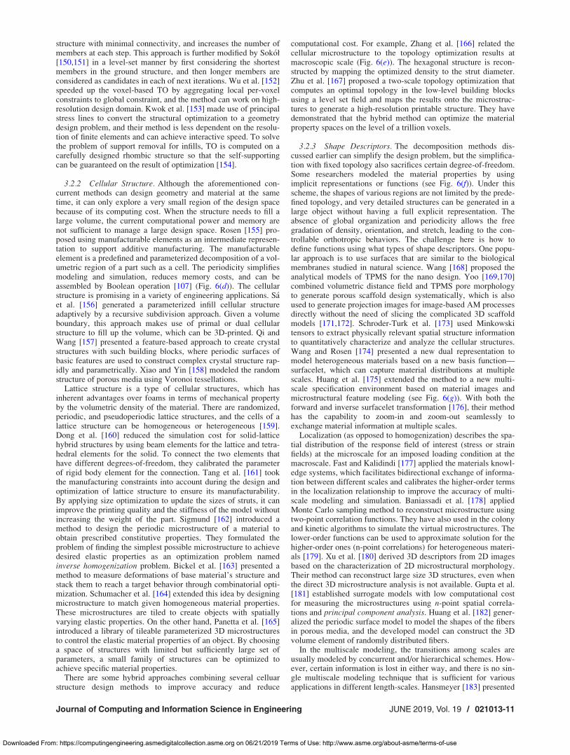
structure with minimal connectivity, and increases the number ofmembers at each step. This approach is further modified by Sok�oł[150,151] in a level-set manner by first considering the shortestmembers in the ground structure, and then longer members areconsidered as candidates in each of next iterations. Wu et al. [152]speeded up the voxel-based TO by aggregating local per-voxelconstraints to global constraint, and the method can work on high-resolution design domain. Kwok et al. [153] made use of principalstress lines to convert the structural optimization to a geometrydesign problem, and their method is less dependent on the resolu-tion of finite elements and can achieve interactive speed. To solvethe problem of support removal for infills, TO is computed on acarefully designed rhombic structure so that the self-supportingcan be guaranteed on the result of optimization [154].
3.2.2 Cellular Structure. Although the aforementioned con-current methods can design geometry and material at the sametime, it can only explore a very small region of the design spacebecause of its computing cost. When the structure needs to fill alarge volume, the current computational power and memory arenot sufficient to manage a large design space. Rosen [155] pro-posed using manufacturable elements as an intermediate represen-tation to support additive manufacturing. The manufacturableelement is a predefined and parameterized decomposition of a vol-umetric region of a part such as a cell. The periodicity simplifiesmodeling and simulation, reduces memory costs, and can beassembled by Boolean operation [107] (Fig. 6(d)). The cellularstructure is promising in a variety of engineering applications. S�aet al. [156] generated a parameterized infill cellular structureadaptively by a recursive subdivision approach. Given a volumeboundary, this approach makes use of primal or dual cellularstructure to fill up the volume, which can be 3D-printed. Qi andWang [157] presented a feature-based approach to create crystalstructures with such building blocks, where periodic surfaces ofbasic features are used to construct complex crystal structure rap-idly and parametrically. Xiao and Yin [158] modeled the randomstructure of porous media using Voronoi tessellations.
Lattice structure is a type of cellular structures, which hasinherent advantages over foams in terms of mechanical propertyby the volumetric density of the material. There are randomized,periodic, and pseudoperiodic lattice structures, and the cells of alattice structure can be homogeneous or heterogeneous [159].Dong et al. [160] reduced the simulation cost for solid-latticehybrid structures by using beam elements for the lattice and tetra-hedral elements for the solid. To connect the two elements thathave different degrees-of-freedom, they calibrated the parameterof rigid body element for the connection. Tang et al. [161] tookthe manufacturing constraints into account during the design andoptimization of lattice structure to ensure its manufacturability.By applying size optimization to update the sizes of struts, it canimprove the printing quality and the stiffness of the model withoutincreasing the weight of the part. Sigmund [162] introduced amethod to design the periodic microstructure of a material toobtain prescribed constitutive properties. They formulated theproblem of finding the simplest possible microstructure to achievedesired elastic properties as an optimization problem namedinverse homogenization problem. Bickel et al. [163] presented amethod to measure deformations of base material’s structure andstack them to reach a target behavior through combinatorial opti-mization. Schumacher et al. [164] extended this idea by designingmicrostructure to match given homogeneous material properties.These microstructures are tiled to create objects with spatiallyvarying elastic properties. On the other hand, Panetta et al. [165]introduced a library of tileable parameterized 3D microstructuresto control the elastic material properties of an object. By choosinga space of structures with limited but sufficiently large set ofparameters, a small family of structures can be optimized toachieve specific material properties.
There are some hybrid approaches combining several celluarstructure design methods to improve accuracy and reduce
computational cost. For example, Zhang et al. [166] related thecellular microstructure to the topology optimization results atmacroscopic scale (Fig. 6(e)). The hexagonal structure is recon-structed by mapping the optimized density to the strut diameter.Zhu et al. [167] proposed a two-scale topology optimization thatcomputes an optimal topology in the low-level building blocksusing a level set field and maps the results onto the microstruc-tures to generate a high-resolution printable structure. They havedemonstrated that the hybrid method can optimize the materialproperty spaces on the level of a trillion voxels.
3.2.3 Shape Descriptors. The decomposition methods dis-cussed earlier can simplify the design problem, but the simplifica-tion with fixed topology also sacrifices certain degree-of-freedom.Some researchers modeled the material properties by usingimplicit representations or functions (see Fig. 6(f)). Under thisscheme, the shapes of various regions are not limited by the prede-fined topology, and very detailed structures can be generated in alarge object without having a full explicit representation. Theabsence of global organization and periodicity allows the freegradation of density, orientation, and stretch, leading to the con-trollable orthotropic behaviors. The challenge here is how todefine functions using what types of shape descriptors. One popu-lar approach is to use surfaces that are similar to the biologicalmembranes studied in natural science. Wang [168] proposed theanalytical models of TPMS for the nano design. Yoo [169,170]combined volumetric distance field and TPMS pore morphologyto generate porous scaffold design systematically, which is alsoused to generate projection images for image-based AM processesdirectly without the need of slicing the complicated 3D scaffoldmodels [171,172]. Schroder-Turk et al. [173] used Minkowskitensors to extract physically relevant spatial structure informationto quantitatively characterize and analyze the cellular structures.Wang and Rosen [174] presented a new dual representation tomodel heterogeneous materials based on a new basis function—surfacelet, which can capture material distributions at multiplescales. Huang et al. [175] extended the method to a new multi-scale specification environment based on material images andmicrostructural feature modeling (see Fig. 6(g)). With both theforward and inverse surfacelet transformation [176], their methodhas the capability to zoom-in and zoom-out seamlessly toexchange material information at multiple scales.
Localization (as opposed to homogenization) describes the spa-tial distribution of the response field of interest (stress or strainfields) at the microscale for an imposed loading condition at themacroscale. Fast and Kalidindi [177] applied the materials knowl-edge systems, which facilitates bidirectional exchange of informa-tion between different scales and calibrates the higher-order termsin the localization relationship to improve the accuracy of multi-scale modeling and simulation. Baniassadi et al. [178] appliedMonte Carlo sampling method to reconstruct microstructure usingtwo-point correlation functions. They have also used in the colonyand kinetic algorithms to simulate the virtual microstructures. Thelower-order functions can be used to approximate solution for thehigher-order ones (n-point correlations) for heterogeneous materi-als [179]. Xu et al. [180] derived 3D descriptors from 2D imagesbased on the characterization of 2D microstructural morphology.Their method can reconstruct large size 3D structures, even whenthe direct 3D microstructure analysis is not available. Gupta et al.[181] established surrogate models with low computational costfor measuring the microstructures using n-point spatial correla-tions and principal component analysis. Huang et al. [182] gener-alized the periodic surface model to model the shapes of the fibersin porous media, and the developed model can construct the 3Dvolume element of randomly distributed fibers.
In the multiscale modeling, the transitions among scales areusually modeled by concurrent and/or hierarchical schemes. How-ever, certain information is lost in either way, and there is no sin-gle multiscale modeling technique that is sufficient for variousapplications in different length-scales. Hansmeyer [183] presented
Journal of Computing and Information Science in Engineering JUNE 2019, Vol. 19 / 021013-11
Downloaded From: https://computingengineering.asmedigitalcollection.asme.org on 06/21/2019 Terms of Use: http://www.asme.org/about-asme/terms-of-use

a procedural subdivision process to articulate the model at multi-ple scales, yet the approach is rather limited only for certain appli-cations. With the growth of computational power and cloudcomputing, the concurrent methods will play a very importantrole—particularly when the response within a microstructure can-not be localized. At the same time, a promising trend of generativedesign [184] can be applied. Nevertheless, the data-drivenmethods and the dual-representation approaches are still the mostpractical strategy at this moment. At present, the material andmanufacturing information of the microstructures can be extractedon-the-fly, so that the demand of memory and commutation isminimized. However, the major challenge is still the high-dimensional optimization during the iterative computation. Onepossible direction is to convert the iterative optimization probleminto a geometric design problem, such that the accuracy does notrely on the resolution of the solution space. But this requires acomplete understanding of the problem and the development ofdesign principles for the problem in different scales.
3.3 Design for Multiform Additive ManufacturingProcesses. With the newly tailor-made materials and the multi-material 3D printing capability enabled by AM technology, multi-form products using intelligently designed layout of variousmaterials such as plastic, elastomer, composites, and shape mem-ory polymer can now be fabricated. Designers can focus more onthe intended forms of a designed product during its usage overtime. In this section, we will review different design methodolo-gies for multiform fabrication and the related form-changingmechanisms.
3.3.1 Folding and Origami. In classical mechanics, motionsbetween rigid bodies are realized by their connections such as kine-matic pairs or joints. The connection could be located at a point oralong a line, such as mechanical linkage or folding. With the helpof additive manufacturing, the kinematic pairs can now be directlyfabricated using different choices of materials, which could resultin a more complex system that cannot be designed and producedbefore. Wang et al. [185] studied mobility and foldability of fold-able mechanisms. Their method is based on the formula of therevolute-joint design related to the joints’ degrees-of-freedom andthe order of wrench system. They described that a shape-shifting
structure can be folded into the same pattern through differentmethods and can also be folded to different patterns.
Recently, one of the active topics in folding mechanism is theorigami (or kirigami) designs. Having the ability of transformingback-and-forth between its stowed state and the deployed state(see Fig. 7(a)), the origami-based mechanisms have many attrac-tive applications, e.g., the origami wheel presented in Ref. [186].Belcastro and Hull [187] used affine transformations to computethe valid origami structures and the mappings between unfoldedand folded configurations. Schenk and Guest [188] proposed amodel for origami structures with elastic creased folds via trussrepresentations. Their model is based on introducing the behaviorof torsional springs at the creases. Tachi [189] used a similarapproach to model the elastic behavior of sheets with creasedfolds and also idealized the folds as torsional springs. He alsosolved the equations of mechanical equilibrium under constraintsassuring that no fold line or boundary edge is elongated. Thismodel provides the theoretical basis for his origami simulationtools (i.e., the freeform rigid origami simulator [190]) to computethe unfolded patterns for a given folded target shape. Zhu et al.[191] developed a method for analyzing surfaces under creasedand bent folds. Their tool allowed for the superposition of foldswith arbitrary sharpness and angle that collectively dictated theultimate shape of the analyzed surface. Recently, Morgan et al.[192] presented a design process for generating origami-adaptedproducts based on an exemplar-based methodology (seeFig. 7(b)). The design process includes (1) evaluating the criteriato verify if the problem is suitable for origami-adapted design, (2)picking seed origami from standard patterns that function close tothe need, (3) modifying fold patterns to meet the design require-ments, and (4) integrating the pattern with material and prototyp-ing. On the other aspect, modeling a freeform surface usingfoldable mechanisms is also relevant to the geometric modeling ofdevelopable surfaces [193–195]. In these approaches, an inversedesign problem—finding the planar structure for a given 3Dtarget—was studied.
3.3.2 Elasticity and Soft Robotics. With the capability ofprinting elastomeric and/or rigid materials, certain mechanicaldeformation to mimic physical objects like gripper [196] (seeFig. 7(c)) and heart [197] can be designed. Most current practices
Fig. 7 (a) An origami antenna in both stowed and deployed states. (b) The database of origami models can be applied to abellows [192]. (c) A hand design using elastomer and joints to achieve different curvatures [196]. (d) Various actuation designsfor soft-robots [198] (Reprinted with permission of Springer Nature# 2015). (e) The database of fiber-reinforced soft actuatorsare used to design for matching the input trajectory [199]. (f) Shape optimization and cutting are done for 4D-printing nonflat-tenable object [66]. (g) A self-transformed flower with designed pattern to constrain the shrinkage of a prestrained film [65].
021013-12 / Vol. 19, JUNE 2019 Transactions of the ASME
Downloaded From: https://computingengineering.asmedigitalcollection.asme.org on 06/21/2019 Terms of Use: http://www.asme.org/about-asme/terms-of-use

are to compute in a trial-and-error manner by using differentactuations such as tensile cables, constraint fibers, and pneumaticbellows [198] (see Fig. 7(d)) and then testing the responses andthe deformations. Connolly et al. [199] created a database of fiber-reinforced soft actuators and developed an automatic selection ofmechanical properties to match the kinematic trajectory of a grip-per using the exemplars in the database (see Fig. 7(e)). In othermethods, material parameters of constitutive model were esti-mated by considering Young’s modulus [200,201] and acquiringcomplex heterogeneous deformation through optimized materialdistribution of Young’s modulus [202]. However, the results gen-erated by these approaches may not be fabricable due to the lim-ited materials that can be 3D printed by current AM processes. Ahalfway approach is to design microstructures with single materialto approximate elasticity for 3D printing [164,165,203], whichhas been discussed in Sec. 3.2.1.
Until today, it is still difficult to directly generate design forperformance and manufacturability. A more common way to gen-erate optimal design is to integrate simulation into the designphase that allows an iterative process to update the design andestimate the physical effects of the changes. Skouras et al. [204]presented a design method for deformable character with a set oftarget-poses as input. The method combines FEA, sparse regulari-zation, and constrained optimization in the design phase to com-pute a set of actuators along with their locations and materialdistribution so that the resulting character exhibits the desireddeformation behavior. As FEA is often the bottleneck in computa-tion, some approaches make use of numerical coarsening[205,206] to speed up the FEA without a huge penalty in accu-racy. Another speedup technique is data-driven methods, whichare effective in the applications that require interactive responsedemand [203].
In fact, the data-driven method is common in the design of softrobot, where 3D printing is getting more and more adopted. Whilecommercial software like ABAQUS and COMSOL can be used in softrobot design [207], Hiller and Lipson [208] developed a platformcalled Voxelyze that is able to generate results of dynamic simula-tion for multimaterial soft objects with a fast simulation. Voxelrepresentation is used for simulating large deformation, and evo-lutionary computation is employed to obtain optimized materialdistributions [209]. Nevertheless, many voxels are needed to rep-resent models with complex shape, which will tremendously slowdown the computation. SOFA [210] is a widely used frameworkin the field of surgical and biomedical simulation. Based onSOFA, Duriez et al. [211–213] developed an asynchronoussimulation framework by considering the trade-off between defor-mation accuracy and computational speed such that a real-timesimulation of soft robots was realized to support interactive defor-mation. Their algorithm uses the iterative method to solve ordi-nary differential equations and transfers boundary conditionsusing Lagrangian multipliers. This method is fast but suffers fromthe problem of numerical accuracy, particularly if there is largerotational deformation. Wang and Hirai [214] presented anoptimization-based method to find an accurate mathematical sim-ulation model for pneumatic driven grippers. With the help ofmass–spring system, Stanley and Okamura [215] presented aclose-loop control for haptic jamming deformable surface. How-ever, they are application-specific and may not be generalized toother domains. Recently, Fang et al. [196] presented a geometry-based approach that can simulate multimaterial actuators in largerotational deformation in a quite accurate way.
3.3.3 Self-Transformation. Sections 3.3.1 and 3.3.2 discussedthe mechanisms of transferring external forces and movement intodeformation either by designed connections or elastic materials.Other research for fabricating smart structures and productsfocuses on the development of self-folding, self-assembly, andprogrammable materials to mimic the biological process such asDNA [216]. Many prototypes have been developed based on dif-ferent materials, fabrication technologies, and external energy
sources [217]. However, most of these prototypes require an addi-tional production step to embed the “programmability” and thepotential energy for transformation, e.g., adding magnets and elas-tic strands, which is difficult. This leads to the development offour-dimensional (4D) printing, which streamlines the process ofproduction for programmable and adaptive materials. There aresurvey papers [62,64,218] reviewing the current 4D printing proc-esses, concepts, and related tools. They have described differentshape-transformation behaviors such as bending and folding, thecommonly used materials and structures, and the shape-shiftingmechanisms. The papers also mentioned that the design for shape-transformation behavior is needed to predict and model the struc-tures, such that the number of trial-and-error experiments can bereduced.
Gladman et al. [77] studied a bilayer structure that is fabricatedby depositing the ink of hydrogel composite in different printpaths for the two layers. They defined the elastic and swelling ani-sotropies by controlling the orientation of cellulose fibrils withinthe hydrogel, and the orientation is computed by the mathematicalrelationships of desired curvatures and the parameters includingelastic moduli, swelling ratios, and layer thicknesses. Kwok et al.[66] pointed out that only developable surfaces can be shaped-transformed from 2D to 3D. Based on differential geometry, theydeveloped a geometry optimization method for freeform surfacesto modify a nonflattenable surface into a flattenable one. Theshape optimization framework also supports topological operatorsby adding cuts to improve the flattenability (see Fig. 7(f)). Denget al. [65] used an exemplar-based approach to approximate asmooth surface. They created a library of constraint patterns withcontrollable variables and studied the relationship between thepatterns and the deformation (see Fig. 7(g)). As a smoothly curvedsurface can be subdivided into patches and approximated by thepatterns in the library, their method can approximate differentfolding types, folding orientation, folding axis, and foldingcurvatures. Kwok and Chen [219] developed a geometry-drivenfinite element method to efficiently simulate shape-transformationbehavior, which can be integrated in the design phase for an itera-tive design algorithm. They also demonstrated that, by using thegeometry-driven finite element framework to understand thematerial distribution and the resulting curvature, a mathematicalmodel can be formulated to design for general freeform shapes.
Since many causes of motion are based on geometric variationssuch as displacement, a more direct way of simulating motion forinput geometric variations rather than using well-defined struc-tural loads is needed to achieve better convergence and accuracy.One of the most recent efforts can be found in Ref. [187].Furthermore, the simulation only solves a forward problem thatdetermines the final shape with given material structures anddeformation principles. A more challenging problem is how todesign the optimal material structure that can be transformed intoa desired shape. This is an inverse design problem, which is thedetermination of the material distribution in a structure based onthe final desired shape and the given deformation principle. Theinverse problem is far more complex in determining a discretesmall-scale material distribution that yields the desired self-transformation behavior. One direction in solving this problem isto apply pattern learning and synthesis techniques with the data-driven approaches. The 1D–2D, 2D–3D, and 3D–3D shape-transformation behaviors should be studied, and various deforma-tion principles need to be fully understood in order to design theevolution of 3D structures.
3.4 Design for Multifunctional Additive ManufacturingProcesses. Earlier additive manufacturing techniques weremainly used to fabricate structural components with mechanicalproperties. With the recent developments of more advancedtechniques [220], AM technology has been used to achieve morefunctionality. Complex multifunctional components can now befabricated through multimaterial and multiscale AM processes,
Journal of Computing and Information Science in Engineering JUNE 2019, Vol. 19 / 021013-13
Downloaded From: https://computingengineering.asmedigitalcollection.asme.org on 06/21/2019 Terms of Use: http://www.asme.org/about-asme/terms-of-use
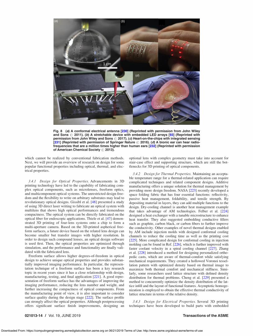
which cannot be realized by conventional fabrication methods.Next, we will provide an overview of research on design for somepopular functional properties including optical, thermal, and elec-trical properties.
3.4.1 Design for Optical Properties. Advancements in 3Dprinting technology have led to the capability of fabricating com-plex optical components, such as microlenses, freeform optics,and multicomponent optical systems. The unrestricted design free-dom and the flexibility to write on arbitrary substrates may lead torevolutionary optical designs. Gissibl et al. [48] presented a studyof using 3D direct laser writing to fabricate an optical system withmultilens that shows high optical performances and tremendouscompactness. The optical system can be directly fabricated on theoptical fiber for endoscopic applications. Thiele et al. [47] demon-strated 3D printing of four-lens systems onto a chip to form amulti-aperture camera. Based on the 3D-printed aspherical free-form surfaces, a future device based on the related lens design canbecome smaller but transfer images with higher resolution. Inorder to design such compound lenses, an optical design softwareis used first. Then, the optical properties are optimized throughsimulation, and the performance and functionality are finally vali-dated with the fabricated lens.
Freeform surface allows higher degrees-of-freedom in opticaldesign to achieve unique optical properties and provides substan-tially improved imaging performance. In particular, the represen-tation technique of a freeform surface has been a key researchtopic in recent years since it has a close relationship with design,manufacturing, testing, and final application [221]. A good repre-sentation of freeform surface has the advantages of improving theimaging performance, reducing the lens number and weight, andfurther increasing the compactness of optical components. Fromthe manufacturing point of view, it is also important to considersurface quality during the design stage [222]. The surface profilecan strongly affect the optical properties. Although postprocessingoffers significant surface finish improvements, designing an
optional lens with complex geometry must take into account forstair-case effect and supporting structure, which are still the bot-tlenecks for 3D printing of optical components.
3.4.2 Design for Thermal Properties. Maintaining an accepta-ble temperature range for a thermal-related application can requirecomplicated techniques and related component designs. Additivemanufacturing offers a unique solution for thermal management byproviding more design freedom. NASA [223] recently developed aspace folding fabric that has four essential functions: reflectivity,passive heat management, foldability, and tensile strength. Bydepositing material in layers, they can add multiple functions to thedesign. Dry-cooling channel is another heat management examplethat takes advantage of AM technologies. Felber et al. [224]designed a heat exchanger with a tunable microstructure to enhanceheat transfer. They also suggested embedding conductive fillerssuch as graphite, carbon black, or carbon fibers to further improvethe conductivity. Other examples of novel thermal designs enabledby AM include injection molds with designed conformal coolingchannels to reduce the cooling time as well as the printing cost[225]. More complicated design for conformal cooling in injectionmolding can be found in Ref. [226], which is further improved withfaster coolant velocity in a spiral cooling channel [227]. Zhanget al. [228] introduced a method for designing personalized ortho-pedic casts, which are aware of thermal-comfort while satisfyingmechanical requirements. They created a hollowed Voronoi tessel-lation pattern with optimized density based on thermal image tomaximize both thermal comfort and mechanical stiffness. Simi-larly, some researchers used lattice structure with defined densitydistribution for thermal problems. Cheng et al. [229] presented amethod to concurrently optimize the density distribution of the lat-tice infill and the layout of functional features. Asymptotic homoge-nization is employed to obtain the effective thermal conductivity oflattice structure in terms of the relative density.
3.4.3 Design for Electrical Properties. Several 3D printingtechniques have been developed to build parts with embedded
Fig. 8 (a) A conformal electrical antenna [230] (Reprinted with permission from John Wileyand Sons # 2011). (b) A stretchable device with embedded LED arrays [93] (Reprinted withpermission from John Wiley and Sons # 2017). (c) Heart-on-the-chips with integrated sensing[231] (Reprinted with permission of Springer Nature # 2016). (d) A bionic ear can hear radio-frequencies that are a million times higher than human ears [232] (Reprinted with permissionof American Chemical Society# 2013).
021013-14 / Vol. 19, JUNE 2019 Transactions of the ASME
Downloaded From: https://computingengineering.asmedigitalcollection.asme.org on 06/21/2019 Terms of Use: http://www.asme.org/about-asme/terms-of-use
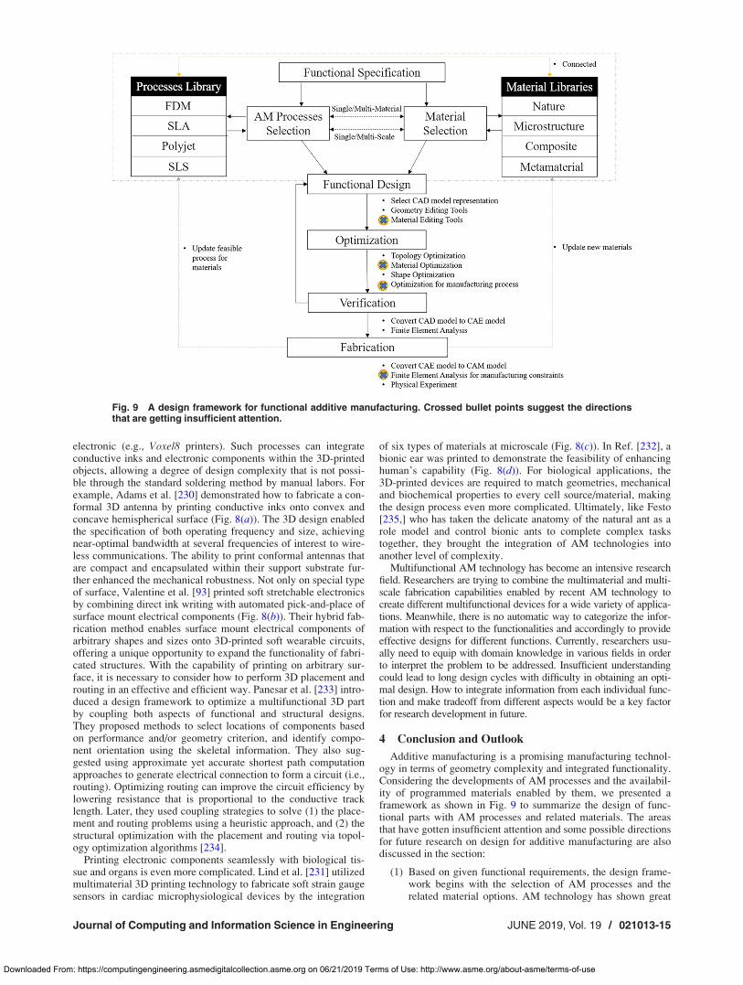
electronic (e.g., Voxel8 printers). Such processes can integrateconductive inks and electronic components within the 3D-printedobjects, allowing a degree of design complexity that is not possi-ble through the standard soldering method by manual labors. Forexample, Adams et al. [230] demonstrated how to fabricate a con-formal 3D antenna by printing conductive inks onto convex andconcave hemispherical surface (Fig. 8(a)). The 3D design enabledthe specification of both operating frequency and size, achievingnear-optimal bandwidth at several frequencies of interest to wire-less communications. The ability to print conformal antennas thatare compact and encapsulated within their support substrate fur-ther enhanced the mechanical robustness. Not only on special typeof surface, Valentine et al. [93] printed soft stretchable electronicsby combining direct ink writing with automated pick-and-place ofsurface mount electrical components (Fig. 8(b)). Their hybrid fab-rication method enables surface mount electrical components ofarbitrary shapes and sizes onto 3D-printed soft wearable circuits,offering a unique opportunity to expand the functionality of fabri-cated structures. With the capability of printing on arbitrary sur-face, it is necessary to consider how to perform 3D placement androuting in an effective and efficient way. Panesar et al. [233] intro-duced a design framework to optimize a multifunctional 3D partby coupling both aspects of functional and structural designs.They proposed methods to select locations of components basedon performance and/or geometry criterion, and identify compo-nent orientation using the skeletal information. They also sug-gested using approximate yet accurate shortest path computationapproaches to generate electrical connection to form a circuit (i.e.,routing). Optimizing routing can improve the circuit efficiency bylowering resistance that is proportional to the conductive tracklength. Later, they used coupling strategies to solve (1) the place-ment and routing problems using a heuristic approach, and (2) thestructural optimization with the placement and routing via topol-ogy optimization algorithms [234].
Printing electronic components seamlessly with biological tis-sue and organs is even more complicated. Lind et al. [231] utilizedmultimaterial 3D printing technology to fabricate soft strain gaugesensors in cardiac microphysiological devices by the integration
of six types of materials at microscale (Fig. 8(c)). In Ref. [232], abionic ear was printed to demonstrate the feasibility of enhancinghuman’s capability (Fig. 8(d)). For biological applications, the3D-printed devices are required to match geometries, mechanicaland biochemical properties to every cell source/material, makingthe design process even more complicated. Ultimately, like Festo[235,] who has taken the delicate anatomy of the natural ant as arole model and control bionic ants to complete complex taskstogether, they brought the integration of AM technologies intoanother level of complexity.
Multifunctional AM technology has become an intensive researchfield. Researchers are trying to combine the multimaterial and multi-scale fabrication capabilities enabled by recent AM technology tocreate different multifunctional devices for a wide variety of applica-tions. Meanwhile, there is no automatic way to categorize the infor-mation with respect to the functionalities and accordingly to provideeffective designs for different functions. Currently, researchers usu-ally need to equip with domain knowledge in various fields in orderto interpret the problem to be addressed. Insufficient understandingcould lead to long design cycles with difficulty in obtaining an opti-mal design. How to integrate information from each individual func-tion and make tradeoff from different aspects would be a key factorfor research development in future.
4 Conclusion and Outlook
Additive manufacturing is a promising manufacturing technol-ogy in terms of geometry complexity and integrated functionality.Considering the developments of AM processes and the availabil-ity of programmed materials enabled by them, we presented aframework as shown in Fig. 9 to summarize the design of func-tional parts with AM processes and related materials. The areasthat have gotten insufficient attention and some possible directionsfor future research on design for additive manufacturing are alsodiscussed in the section:
(1) Based on given functional requirements, the design frame-work begins with the selection of AM processes and therelated material options. AM technology has shown great
Fig. 9 A design framework for functional additive manufacturing. Crossed bullet points suggest the directionsthat are getting insufficient attention.
Journal of Computing and Information Science in Engineering JUNE 2019, Vol. 19 / 021013-15
Downloaded From: https://computingengineering.asmedigitalcollection.asme.org on 06/21/2019 Terms of Use: http://www.asme.org/about-asme/terms-of-use

advantages in fabricating multifunctional structures. How-ever, there are still several problems that need to beaddressed. For example, multifunctionality of a designedcomponent usually requires using multimaterial 3D printingprocesses. However, the kinds of materials that are avail-able for such multimaterial 3D printing processes are usu-ally limited. The study to broaden the materials that can be3D printed as well as to enable novel composites is a criti-cal task in the future. In addition, it is very challenging forcurrent 3D printing technology to process materials in dif-ferent categories due to the incompatible forming condi-tions. New material deposition mechanisms may alsoenable multimaterial 3D printing with higher resolution andfaster speed. In the hydrodynamic level, some multifunc-tional bioinspired structures possess multiscale features,which are difficult for current 3D printing processes to rep-licate. The further development of multifunctional AMprocesses will lie in the combination of multimaterial andmultiscale AM technology.A database linking AM processes, material and func-
tional specification will also become urgently needed. Asshown in Fig. 9, two libraries are established that need toallow the interoperability (yellow dotted line) betweenthem. A comprehensive collection of materials (includesprogramed materials) with experimental data from therelated fabrication processes can support designers to deter-mine how functions are related to the manufacture con-straints and material properties. Every profile of materialsshould be linked with at least one AM process, and eachAM process should provide a list of manufacturable materi-als along with the necessary values of process parameters.The connection guarantees that any profiles created in thelibraries are feasible and practicable. In the AM process/material selection stage, there exists a two-way couplingrelationship (as shown in black dotted arrows). The rela-tionship indicates that not only the process could beaffected by the available materials, the material selection isalso affected by the manufacturability. Therefore, in theearly stage of functional design, it is very important to beguided by the established libraries.
(2) One important challenge is to set an appropriate representa-tion model that is reliable, reasonably accurate, computa-tionally efficient, user-friendly, and easy to modify, shareand store [236]. For example, the overall characterizationof microstructures needs to be improved. A standard proto-col for assessing the dimensions/microstructure/mechanicalperformance needs to be developed. Multifunctional addi-tive manufacturing is a new emerging technology and stillbeing under development. As this area of manufacturing isnascent, most ongoing research goes into materials and pro-cess configuration. Little work has been carried out ondeveloping the design methodologies specifically for multi-functional AM processes. Designing a multifunctionaldevice with prefabricated components (e.g., circuits andsensors) requires a more complex design representationwhen compared to a simple mechanical structure, due tothe existence of nonmechanical features, e.g., optical, ther-mal, and electronic features. These simultaneouslydesigned features require more than one design methodolo-gies, and their combination/coupling issues are manuallyhandled in current research. A thorough design considera-tion for the currently existing procedures and applicationsis needed. In the future, it is expected to have proper designoperations and representation to allow multifunctionaldesign on arbitrary geometry, arbitrary material composi-tion, and arbitrary size scales.
(3) From our review, it was found that most of current designmethodologies are through an iterative process to optimizethe simulation-based design results. The most common toolin computer-aided engineering for estimating the behavior
of an object is finite element modeling (FEM). However,the FEM framework is known to be computationally expen-sive, and relies on accurate input of structural loads andmaterial properties. As a consequence, simplifying theFEM computation is an active and emerging topic, espe-cially when the capability of AM is extending to multiplematerials with complex shape and topology. When thefunctional specifications are getting more complicated, effi-cient and effective optimization methods on geometry andmaterials are particularly essential that need to bedeveloped.
(4) Eliminating the information gap between the design phaseand the manufacturing process is also very important. Thefinal fabricated product needs to reflect the design as bestas possible. One major factor that leads to the discrepancyis the human involvement during the design-to-fabricationprocess. Automating some critical steps, such as processparameter controls (e.g., extrusion temperature and overlappercentage) and design constraints (e.g., building orienta-tion and material selection), could significantly reduce mis-takes the may be made during the design-to-fabricationprocess. In other words, managing and interpreting data hascome to be regarded as a key concern across the design andmanufacturing processes. In particular, when it comes tomultiple materials, data are certainly needed for reproduc-tion and control. To establish the foundation for future AMindustry, one way is to associate the data with the men-tioned material library, which consists of a comprehensivedescription of each digital material. The library is thenopened for the assessment in different applications. There-fore, whenever a new digital material is successfullyprinted, the database will be updated for verification. In thelong-term, using AM machines to “read” the library andassist in design stage could better handle more complexproblems.
(5) From the process perspective, despite the recent advancesin 3D printing, there are still plenty challenges that need tobe addressed in future. For example, the material selectionfor the 3D printing of shape-changing structures is still lim-ited. Only a few categories of polymers are currently avail-able, which significantly restrict the potential applicationsof shape-changing structures. Moreover, the stimuli used totrigger shape-changing behaviors are still based on labora-tory environments and might not be broadly applicable tothe real world. Meanwhile, the shape-changing behaviorstriggered by these stimuli have big variations and cannot bereliably and accurately controlled, which makes 4D print-ing difficult to be applied in an actual human-centered sys-tem. In the future, more new materials need to be exploredand incorporated into printed structures to achieve multi-functional properties, e.g., ceramics with mechanical rigid-ity, scaffolds with bio-degradability, and nanocompositesfor chemical or thermal resistance.
In addition, multimaterial AM processes are difficult to achievemicro- and nanoscale features due to some crucial problems ofmultimaterial printing technology such as material blur. The prob-lem exists in the adjacent regions of different 3D-printed materi-als, which restrict the resolution of multimaterial printing. Asdiscussed before, an effective material changing system is criticalfor multimaterial AM process to achieve desired functional per-formance on the 3D-printed structures. Researchers have madestrides to expand the dimensional span of AM technologies,achieving fabricable feature sizes ranging from dozens of centi-meters to several microns. Recent progress in the development ofmultiscale 3D printing technologies also shows applications of 3Dprinting as a tool to validate designs with advanced materials andmultiscale structures. To address the known limitations of AMprocesses such as fabrication efficiency and limited materials,recent research also reveals a feasible solution by integrating AM
021013-16 / Vol. 19, JUNE 2019 Transactions of the ASME
Downloaded From: https://computingengineering.asmedigitalcollection.asme.org on 06/21/2019 Terms of Use: http://www.asme.org/about-asme/terms-of-use

with traditional manufacturing processes. Such hybrid processesbased on the integration of multiple AM processes and other tradi-tional fabrication processes provide the capability of buildingmultiscale and multimaterial objects. The hybrid process develop-ment is becoming a trending topic for additive manufacturingresearch.
In summary, many research groups are currently exploiting thefabrication capabilities of AM to meet the ever-changing needsfor high-performance engineering systems. It has led to theongoing development of new design methodologies for integrat-ing the state-of-the-art AM technologies and programmable mate-rials to enable new functional performance or novel products. Inthe future, we envision a more collaborative and connectivedesign-to-fabrication process codeveloped by the design and man-ufacturing communities. Together with interdisciplinary teams,multifunctional design challenges can be addressed by developingthe next generation of computational design system for additivemanufacturing.
Acknowledgment
The authors acknowledge the support from USC’s Daniel J.Epstein Institute.
Funding Data
� National Science Foundation (NSF), Directorate for Engi-neering (Grant Nos. CMMI 1151191 and CMMI 1663663).
References[1] Altair, 2017, “OptiStruct,” Troy, MI, accessed Nov. 20, 2018, https://altairhy-
perworks.com/product/OptiStruct[2] Hu, Z., Thiyagarajan, K., Bhusal, A., Letcher, T., Fan, Q., Liu, Q., and Salem,
D., 2017, “Design of Ultra-Lightweight and High-Strength Cellular StructuralComposites Inspired by Biomimetics,” Compos. Part B: Eng., 121, pp.108–121.
[3] Compton, B., and Lewis, J., 2014, “3D-Printing of Lightweight CellularComposites,” Adv. Mater., 26(34), pp. 5930–5935.
[4] Gu, G. X., Takaffoli, M., Hsieh, A., and Buehler, M., 2017, “HierarchicallyEnhanced Impact Resistance of Bioinspired Composites,” Adv. Mater.,29(28), p. 1700060.
[5] Yang, Y., Chen, Z., Song, X., Zhang, Z., Zhang, J., Shung, K. K., Zhou, Q.,and Chen, Y., 2017, “Biomimetic Anisotropic Reinforcement Architecturesby Electrically Assisted Nanocomposite 3D Printing,” Adv. Mater., 29(11),p. 1605750.
[6] Wang, K., Wu, C., Qian, Z., Zanga, C., and Wanga, B., 2016, “Dual-Material3D Printed Metamaterials With Tunable Mechanical Properties for Patient-Specific Tissue-Mimicking Phantoms,” Addit. Manuf., 12, pp. 31–37.
[7] Saxena, K. K., Calius, E. P., and Das, R., 2016, “Tailoring Cellular Auxeticsfor Wearable Applications With Multimaterial 3D Printing,” ASME Paper No.IMECE2016-67556.
[8] El-Sherbiny, I. M., and Yacoub, M. H., 2013, “Hydrogel Scaffolds for TissueEngineering: Progress and Challenges,” Global Cardiol. Sci. Pract., 3, pp.316–342.
[9] Yang, Y., Li, X., Zheng, X., Chen, Z., Zhou, Q., and Chen, Y., 2018, “3D-Printed Biomimetic Super-Hydrophobic Structure for Microdroplet Manipula-tion and Oil/Water Separation,” Adv. Mater., 30(9), p. 1704912.
[10] Vaezi, M., Seitz, H., and Yang, S., 2013, “A Review on 3D Micro-AdditiveManufacturing Technologies,” Int. J. Adv. Manuf. Technol., 67(5–8), pp.1721–1754.
[11] Frazier, W. E., 2014, “Metal Additive Manufacturing: A Review,” J. Mater.Eng. Perform., 23(6), pp. 1917–1928.
[12] Huang, S., Liu, P., Mokasdar, A., and Hou, L., 2013, “Additive Manufacturingand Its Societal Impact: A Literature Review,” Int. J. Adv. Manuf. Technol.,67(5–8), pp. 1191–1203.
[13] Gao, W., Zhang, Y., Ramanujan, D., Ramani, K., Chen, Y., Williams, C. B.,Wang, C. C. L., Shin, Y. C., Zhang, S., and Zavattieri, P. D., 2015, “TheStatus, Challenges, and Future of Additive Manufacturing in Engineering,”Comput. Aided Des., 69, pp. 65–89.
[14] Guo, N., and Leu, M., 2013, “Additive Manufacturing: Technology, Applica-tions and Research Needs,” Front. Mech. Eng., 8(3), pp. 215–243.
[15] Kong, Y. L., Tamargo, I. A., Kim, H., Johnson, B. N., Gupta, M. K., Koh,T.-W., Chin, H.-A., Steingart, D. A., Rand, B. P., and McAlpine, M. C., 2014,“3D Printed Quantum Dot Light-Emitting Diodes,” Nano Lett., 14(12), pp.7017–7023.
[16] Espalin, D., Ramirez, J. A., Medina, F., and Wicker, R., 2014, “Multi-Material, Multi-Technology FDM: Exploring Build Process Variations,”Rapid Prototyping J., 20(3), pp. 236–244.
[17] Oxman, N., Tsai, E., and Firstenberg, M., 2012, “Digital Anisotropy: A Vari-able Elasticity Rapid Prototyping Platform,” Virtual Phys. Prototyping, 7(4),pp. 261–274.
[18] Sitthi-Amorn, P., Ramos, J. E., Wangy, Y., Kwan, J., Lan, J., Wang, W., andMatusik, W., 2015, “MultiFab: A Machine Vision Assisted Platform forMulti-Material 3D Printing,” ACM Trans. Graph., 34(4), p. 129.
[19] Yang, H., Lim, J., Liu, Y., Qi, X., Yap, Y., Dikshit, V., Yeong,W. Y., andWei, J., 2017, “Performance Evaluation of ProJet Multi-Material Jetting 3DPrinter,” Virtual Phys. Prototyping, 12(1), pp. 95–103.
[20] Willis, K., Brockmeyer, E., Hudson, S., and Poupyrev, I., 2012, “PrintedOptics: 3D Printing of Embedded Optical Elements for Interactive Devices,”25th Annual ACM Symposium on User Interface Software and Technology,Cambridge, MA, Oct. 7, pp. 589–598.
[21] Li, X., and Chen, Y., 2017, “Micro-Scale Feature Fabrication Using ImmersedSurface Accumulation,” J. Manuf. Process., 28(3), pp. 531–540.
[22] Wang, Q., Jackson, J., Ge, Q., Hopkins, J., Spadaccini, C., and Fang, N., 2016,“Lightweight Mechanical Metamaterials With Tunable Negative ThermalExpansion,” Phys. Rev. Lett., 117(17), p. 175901.
[23] Ge, Q., Sakhaei, A., Lee, H., Dunn, C., Fang, N., and Dunn, M., 2016,“Multimaterial 4D Printing With Tailorable Shape Memory Polymers,” Sci.Rep., 6, p. 31110.
[24] Choi, J.-W., Kim, H.-C., and Wicker, R., 2011, “Multi-Material Stereo-lithography,” J. Mater. Process. Technol., 211(3), pp. 318–328.
[25] Zhou, C., Chen, Y., Yang, Z., and Khoshnevis, B., 2011, “Development of aMulti-Material Mask-Image-Projection-Based Stereolithography for the Fabri-cation of Digital Materials,” 22nd International Symposium on Solid FreeformFabrication, Austin, TX, Aug. 8, pp. 65–80.
[26] Melnikova, R., Ehrmann, A., and Finsterbusch, K., 2014, “3D Printing ofTextile-Based Structures by Fused Deposition Modelling (FDM) With Differ-ent Polymer Materials,” IOP Conf. Ser. Mater. Sci. Eng., 62(1), p. 012018.
[27] Jafari, M., Han, W., Mohammadi, F., Safari, A., Danforth, S., and Langrana,N., 2000, “A Novel System for Fused Deposition of Advanced MultipleCeramics,” Rapid Prototyping J., 6(3), pp. 161–175.
[28] Salea, A., Prathumwan, R., Junpha, J., and Subannajui, K., 2017, “MetalOxide Semiconductor 3D Printing: Preparation of Copper (ii) Oxide by FusedDeposition Modelling for Multi-Functional Semiconducting Applications,”J. Mater. Chem. C, 5(19), pp. 4614–4620.
[29] Liu, W., Zhang, Y. S., Heinrich, M. A., Ferrari, F. D., Jang, H. L., Bakht,S. M., Alvarez, M. M., Yang, J., Li, Y.-C., Santiago, G. T.-D., Miri, A. K.,Zhu, K., Khoshakhlagh, P., Prakash, G., Cheng, H., Guan, X., Zhong, Z., Ju,J., Zhu, G. H., Jin, X., and Shin, S. R., 2016, “Rapid Continuous MultimaterialExtrusion Bioprinting,” Adv. Mater., 29(3), p. 1604630.
[30] Vaezi, M., Chianrabutra, S., Mellor, B., and Yang, S., 2013, “Multiple Mate-rial Additive Manufacturing—Part 1: A Review,” Virtual Phys. Prototyping,8(1), pp. 19–50.
[31] Liu, K., and Lei, J., 2011, “Multifunctional Integration: From Biological toBio-Inspired Materials,” ACS Nano, 5(9), pp. 6786–6790.
[32] Choi, J., Yamashita, M., Sakakibara, J., Kaji, Y., Oshika, T., and Wicker, R.,2010, “Combined Micro and Macro Additive Manufacturing of a SwirlingFlow Coaxial Phacoemulsifier Sleeve With Internal Micro-Vanes,” BiomedMicrodev., 12(5), pp. 875–886.
[33] Li, X., Baldacchin, T., Song, X., and Chen, Y., 2016, “Multi-Scale AdditiveManufacturing: An Investigation on Building Objects With Macro-, Micro-and Nano-Scales Features,” 11th International Conference on Micro Manufac-turing, Irvine, CA, Mar. 29–31, p. 96.
[34] Li, X., Yang, Y., and Chen, Y., 2017, “Bio-Inspired Micro-Scale Texture Fab-rication Based on Immersed Surface Accumulation Process,” World Congresson Micro and Nano Manufacturing Conference, Kaohsiung, Taiwan, Mar.27–30, pp. 33–36.
[35] Chen, Y., Mao, H., and Li, X., 2016, “Mask Video Projection BasedStereolithography With Continuous Resin Flow,” University of Southern Cali-fornia, Los Angeles, CA, Patent No. US20160368210A1.
[36] Pan, Y., Zhao, X., Zhou, C., and Chen, Y., 2012, “Smooth Surface Fabrication inMask Projection Based Stereolithography,” J. Manuf. Processes, 14(4), pp. 460–470.
[37] Emami, M., Barazandeh, F., and Yaghmai, F., 2014, “Scanning-ProjectionBased Stereolithography: Method and Structure,” Sens. Actuators A: Phys.,218(1), pp. 116–124.
[38] Ha, Y.-M., Park, I.-B., Kim, H.-C., and Le, S.-H., 2010, “Three-DimensionalMicrostructure Using Partitioned Cross-Sections in Projection Micro-stereolithography,” Int. J. Precis. Eng. Manuf., 11(2), pp. 335–340.
[39] Lee, M., Cooper, G., Hinkley, T., Gibson, G., Padgett, M., and Cronin, L.,2015, “Development of a 3D Printer Using Scanning Projection Stereo-lithography,” Sci. Rep., 5, p. 9875.
[40] Pan, Y., and Dagli, C., 2016, “Dynamic Resolution Control in aLaser Projection Based Stereolithography System,” Rapid Prototyping J.,23(1), pp. 190–200.
[41] Li, Y., Mao, H., Liu, H., Yao, Y., Wang, Y., Song, B., Chen, Y., and Wu, W.,2015, “Stereolithography With Variable Resolutions Using Optical Filter WithHigh-Contrast Gratings,” J. Vac. Sci. Technol. B, 33(6), p. 06F604.
[42] Mao, H., Leung, Y.-S., Li, Y., Hu, P., Wu, W., and Chen, Y., 2017,“Multiscale Stereolithography Using Shaped Beams,” ASME J. Micro- Nano-Manuf., 5(4), p. 040905.
[43] Wu, W., DeConinck, A., and Lewis, J., 2011, “Omnidirectional Printing of 3DMicrovascular Networks,” Adv. Mater., 23(24), pp. H178–H183.
[44] Qin, Z., Compton, B., Lewis, J., and Buehler, M., 2015, “Structural Optimiza-tion of 3D-Printed Synthetic Spider Webs for High Strength,” Nat. Commun.,6, p. 7038.
Journal of Computing and Information Science in Engineering JUNE 2019, Vol. 19 / 021013-17
Downloaded From: https://computingengineering.asmedigitalcollection.asme.org on 06/21/2019 Terms of Use: http://www.asme.org/about-asme/terms-of-use

[45] Thiele, S., Arzenbacher, K., Gissibl, T., Giessen, H., and Herkommer, A.,2017, “3D-Printed Eagle Eye: Compound Microlens System for FoveatedImaging,” Sci. Adv., 3(2), p. e1602655.
[46] Gissibl, T., Thiele, S., Herkommer, A., and Giessen, H., 2016, “Two-PhotonDirect Laser Writing of Ultracompact Multi-Lens Objectives,” Nat. Photonics,10(8), pp. 554–560.
[47] Kolesky, D., Truby, R., Gladman, A., Busbee, T., Homan, K., and Lewis, J.,2014, “3D Bioprinting of Vascularized, Heterogeneous Cell-Laden TissueConstructs,” Adv. Mater., 26(19), pp. 3124–3130.
[48] Au, A., Huynh, W., Horowitz, L., and Folch, A., 2016, “3D-Printed Micro-fluidics,” Angew. Chem. Int. Ed., 55(12), pp. 3862–3881.
[49] O’Bryan, C., Bhattacharjee, T., Hart, S., Kabb, C., Schulze, K., Chilakala, I.,Sumerlin, B., Sawyer, W., and Angelini, T., 2017, “Self-Assembled Micro-Organogels for 3D Printing Silicone Structures,” Sci. Adv., 3(5), p. e1602800.
[50] Hinton, T., Jallerat, Q., Palchesko, R. N., Park, J., Grodzicki, M., Shue, H.-J.,Ramadan, M., Hudson, A., and Feinberg, A., 2015, “Three-Dimensional Print-ing of Complex Biological Structures by Freeform Reversible Embedding ofSuspended Hydrogels,” Sci. Adv., 1(9), p. e1500758.
[51] Bhattacharjee, T., Zehnder, S., Rowe, K., Jain, S., Nixon, R., Sawyer, W., andAngelini, T., 2018, “Writing in the Granular Gel Medium,” Sci. Adv., 1(8),p. e1500655.
[52] Lee, V., Lanzi, A., Ngo, H., Yoo, S.-S., Vincent, P., and Dai, G., 2014, “Generationof Multi-Scale Vascular Network System Within 3D Hydrogel Using 3D Bio-Printing Technology,” Cellular Mol. Bioengineering, 7(3), pp. 460–472.
[53] Yang, Y., Song, X., Li, X., Chen, Z., Zhou, C., Zhou, Q., and Chen, Y., 2018,“Recent Progress in Biomimetic Additive Manufacturing Technology: FromMaterials to Functional Structures,” Adv. Mater., 30(36), p. 1706539.
[54] Wen, L., Weaver, J., and Lauder, G., 2017, “Biomimetic Shark Skin:Design, Fabrication and Hydrodynamic Function,” J. Exp. Biol., 217(10), pp.1656–1666.
[55] Bai, L., Xie, Z., Wang, W., Yuan, C., Zhao, Y., Mu, Z., Zhong, Q., and Gu,Z., 2014, “Bio-Inspired Vapor-Responsive Colloidal Photonic Crystal Patternsby Inkjet Printing,” ACS Nano, 8(11), pp. 11094–11100.
[56] Tibbits, S., 2014, “4D Printing: Multi-Material Shape Change,” Archit. Des.,84(1), pp. 116–121.
[57] Tibbits, S., McKnelly, C., Olguin, C., Dikovsky, D., and Hirsch, S., 2014, “4DPrinting and Universal Transformation,” 34th Annual Conference of the Asso-ciation for Computer Aided Design in Architecture, Los Angeles, CA, Oct.23–25, pp. 539–548.
[58] Ge, Q., Qi, H., and Dunn, M., 2013, “Active Materials by Four-DimensionPrinting,” Appl. Phys. Lett., 103(13), p. 131901.
[59] Deng, D., and Chen, Y., 2015, “Origami-Based Self-Folding Structure Designand Fabrication Using Projection Based Stereolithography,” ASME J. Mech.Des., 137(2), p. 021701.
[60] Deng, D., Kwok, T.-H., and Chen, Y., 2017, “Four-Dimensional Printing:Design and Fabrication of Smooth Curved Surface Using Controlled Self-Folding,” ASME J. Mech. Des., 139(8), p. 081702.
[61] Kwok, T.-H., Wang, C. C. L., Deng, D., Zhang, Y., and Chen, Y.,2015, “Four-Dimensional Printing for Freeform Surfaces: Design Optimiza-tion of Origami and Kirigami Structures,” ASME J. Mech. Des., 137(11),p. 111413.
[62] Momeni, F., Hassani, S., Liu, N. X., and Ni, J., 2017, “A Review of 4DPrinting,” Mater. Des., 122, pp. 42–79.
[63] Ding, Z., Yuan, C., Peng, X., Wang, T., Qi, H., and Dunn, M., 2017, “Direct4D Printing Via Active Composite Materials,” Sci. Adv., 3(4), p. e1602890.
[64] Khoo, Z. X.,Teoh, J. E. M., Liu, Y., Chua, C. K., Yang, S., An, J., Leong, K.F., and Yeong, W. Y., 2015, “3D Printing of Smart Materials: A Review onRecent Progresses in 4D Printing,” Virtual Phys. Prototyping, 10(3), pp.103–122.
[65] Chae, M., Hunter-Smith, D., De-Silva, I., Tham, S., Spychal, R., and Rozen,W., 2015, “Four-Dimensional (4D) Printing: A New Evolution in ComputedTomography-Guided Stereolithographic Modeling. Principles andApplication,” J. Reconstr. Microsurg., 31(6), pp. 458–463.
[66] Ge, Q., Dunn, C., Qi, H., and Dunn, M., 2014, “Active Origami by 4DPrinting,” Smart Mater. Struct., 23(9), p. 094007.
[67] Sidorenko, A., Krupenkin, T., Taylor, A., Fratzl, P., and Aizenberg, J., 2007,“Reversible Switching of Hydrogel-Actuated Nanostructures Into ComplexMicropatterns,” Science, 315(5811), pp. 487–490.
[68] Deng, D., Yang, Y., Chen, Y., Lan, X., and Tice, J., 2017, “Accurately Con-trolled Sequential Self-Folding Structures by Polystyrene Film,” Smart Mater.Struct., 26(8), p. 085040.
[69] Yang, H., Leow, W., Wang, T., Wang, J., Yu, J., He, K., Qi, D., Wan, C., andChen, X., 2017, “3D Printed Photoresponsive Devices Based on Shape Mem-ory Composites,” Adv. Mater., 29(33), p. 1701627.
[70] Liu, Y., Shaw, B., Dickey, M., and Genzer, J., 2017, “Sequential Self-Foldingof Polymer Sheets,” Sci. Adv., 3(3), p. e1601417.
[71] Armon, S., Efrati, E., Kupferman, R., and Sharon, E., 2011,“Geometry and Mechanics in the Opening of Chiral Seed Pods,” Science,333(6050), pp. 1726–1730.
[72] Correa, D., Papadopoulou, A., Guberan, C., Jhaveri, N., Reichert, S., Menges,A., and Tibbits, S., 2015, “3D-Printed Wood: Programming HygroscopicMaterial Transformations,” 3D Printing Addit. Manuf., 2(3), pp. 106–116.
[73] Bargardi, F. L., Ferrand, H. L., Libanori, R., and Studart, A., 2016, “Bio-Inspired Self-Shaping Ceramics,” Nat. Commun., 7, p. 13912.
[74] Erb, R. M., Sander, J. S., Grisch, R., and Studart, A., 2013, “Self-ShapingComposites With Programmable Bioinspired Microstructures,” Nat.Commun., 4, p. 1712.
[75] Kokkinis, D., Schaffner, M., and Studart, A., 2015, “Multimaterial MagneticallyAssisted 3D Printing of Composite Materials,” Nat. Commun., 6, p. 8643.
[76] Huang, L., Jiang, R., Wu, J., Song, J., Bai, H., Li, B., Zhao, Q., and Xie, T.,2017, “Ultrafast Digital Printing Toward 4D Shape Changing Materials,” Adv.Mater., 29(7), p. 1605390.
[77] Gladman, A., Matsumoto, E., Nuzzo, R., Mahadevan, L., and Lewis, J., 2016,“Biomimetic 4D Printing,” Nat. Mater., 15(4), pp. 413–418.
[78] Zhang, Q., Yan, D., Zhang, K., and Hu, G., 2015, “Pattern Transformation ofHeat-Shrinkable Polymer by Three-Dimensional (3D) Printing Technique,”Sci. Rep., 5, p. 8936.
[79] Muth, J. T., Vogt, D. M., Truby, R. L., Meng€uc, Y., and Kolesky, D. B., 2014,“Embedded 3D Printing of Strain Sensors Within Highly StretchableElastomers,” Adv. Mater., 26(36), pp. 6307–6312.
[80] Chizari, K., Daoud, M., Ravindran, A., and Therriault, D., 2016, “3D Printingof Highly Conductive Nanocomposites for the Functional Optimization of Liq-uid Sensors,” Small, 12(44), pp. 6076–6082.
[81] Frutiger, A., Muth, J., Vogt, D., Menguc, Y., Campo, A., Valentine, A.,Walsh, C., and Lewis, J., 2015, “Capacitive Soft Strain Sensors ViaMulticore–Shell Fiber Printing,” Adv. Mater., 27(15), pp. 2440–2446.
[82] Kim, K., Park, J., Suh, J.-H., Kim, M., Jeong, Y., and Park, I., 2017, “3DPrinting of Multiaxial Force Sensors Using Carbon Nanotube (CNT)/Thermoplastic Polyurethane (TPU) Filaments,” Sens. Actuators A: Phys., 263,pp. 493–500.
[83] Lei, Z., Wang, Q., and Wu, P., 2017, “A Multifunctional Skin-Like Sensor Basedon a 3D Printed Thermo-Responsive Hydrogel,” Mater. Horiz., 4, pp. 694–700.
[84] Yang, Y., Chen, Z., Song, X., Zhu, B., Hsiai, T., Wu, P.-I., Xiong, R., Shi, J.,and Chen, Y., 2016, “Three Dimensional Printing of High Dielectric CapacitorUsing Projection Based Stereolithography Method,” Nano Energy, 22, pp.414–421.
[85] Chen, Z., Song, X., Lei, L., Chen, X., Fei, C., Chiu, C., Qian, X., Ma, T.,Yang, Y., and Shung, K., 2016, “3D Printing of Piezoelectric Element forEnergy Focusing and Ultrasonic Sensing,” Nano Energy, 27, pp. 78–86.
[86] Lv, J., Gong, Z., He, Z., Yang, J., Chen, Y., Tang, C., Liu, Y., Fan, M., andLau, W.-M., 2017, “3D Printing of a Mechanically Durable SuperhydrophobicPorous Membrane for Oil–Water Separation,” J. Mater. Chem. A, 5(24), pp.12435–12444.
[87] Guo, S.-Z., Qiu, K., Meng, F., Park, S., and McApine, M., 2017, “3D PrintedStretchable Tactile Sensors,” Adv. Mater., 29(27), p. 1701218.
[88] Darabi, M., Khosrozadeh, A., Mbeleck, R., Liu, Y., Chang, Q., Jiang, J., Cai,J., Wang, Q., Luo, G., and Xing, M., 2017, “Skin-Inspired MultifunctionalAutonomic-Intrinsic Conductive Self-Healing Hydrogels With Pressure Sensi-tivity, Stretchability, and 3D Printability,” Adv. Mater., 29(31), p. 1700533.
[89] Yao, Y., Fu, K., Yan, C., Dai, J., Chen, Y., Wang, Y., Zhang, B., Hitz, E., andHu, L., 2016, “Three-Dimensional Printable High-Temperature and High-RateHeaters,” ACS Nano, 10(5), pp. 5272–5279.
[90] Liu, X., Yuk, H., Lin, S., Parada, G., Tang, T.-C., Tham, E., Fuente-Nunez,C., Lu, T., and Zhao, X., 2018, “3D Printing of Living Responsive Materialsand Devices,” Adv. Mater., 30(4), p. 1704821.
[91] Shin, S., Farzad, R., Tamayol, A., Manoharan, V., Mostafalu, P., Zhang, Y.,Akbari, M., Jung, S., Kim, D., Comotto, M., Annabi, N., Al-Hazmi, F., Dok-meci, M., and Khademhosseini, A., 2016, “A Bioactive Carbon Nanotube-Based Ink for Printing 2D and 3D Flexible Electronics,” Adv. Mater., 28(17),pp. 3280–3289.
[92] Jakus, A., Secor, E., Rutz, A., Jordan, S., Hersam, M., and Shah, R., 2015,“Three-Dimensional Printing of High-Content Graphene Scaffolds for Elec-tronic and Biomedical Applications,” ACS Nano, 9(4), pp. 4636–4648.
[93] Valentine, A. D., Busbee, T., Boley, J., Raney, J., Chortos, A., Kotikian, A.,Berrigan, J., and Durstock, M., 2017, “Hybrid 3D Printing of Soft Electro-nics,” Adv. Mater., 29(40), p. 1703817.
[94] Brochu, T., and Schmidt, R., 2017, “Geometric Modeling of Multi-MaterialPrinted Objects,” Eurographics Association Conference, Carmel-by-the-Sea,CA, Apr. 13–15.
[95] Al-Ketan, O., Al-Rub, R. K. A., and Rowshan, R., 2017, “Mechanical Proper-ties of a New Type of Architected Interpenetrating Phase Composite Materi-als,” Adv. Mater. Technol., 2(2), p. 1600235.
[96] Garland, A., and Fadel, G., 2015, “Design and Manufacturing FunctionallyGradient Material Objects With an Off the Shelf Three-Dimensional Printer:Challenges and Solutions,” ASME J. Mech. Des., 137(11), p. 111407.
[97] Leung, Y.-S., Mao, H., and Chen, Y., “Approximate Functionally GradedMaterials for Multi-Material Additive Manufacturing,” ASME Paper No.DETC2018-86391.
[98] Sigmund, O., and Torquato, S., 1999, “Design of Smart Composite MaterialsUsing Topology Optimization,” Smart Mater. Struct., 8(3), pp. 365–379.
[99] Malek, S., Raney, J., Lewis, J. A., and Gibson, L., 2017, “Lightweight 3DCellular Composites Inspired by Balsa,” Bioinspiration Biomimetics, 12(2),p. 026014.
[100] Quan, Z., Wu, A., Keefe, M., Qin, X., and Yu, J., 2015, “Additive Manufactur-ing of Multi-Directional Preforms for Composites: Opportunities andChallenges,” Mater. Todays, 18(9), pp. 503–512 .
[101] Long, K., Yuan, P., Xu, S., and Xie, Y., 2018, “Concurrent TopologicalDesign of Composite Structures and Materials Containing Multiple Phases ofDistinct Poisson’s Ratios,” Eng. Optim., 50(4), pp. 599–614.
[102] Kapfer, S., Hyde, S., Mecke, K., Arns, C. H., and Schr€oder-Turk, G. E., 2011,“Minimal Surface Scaffold Designs for Tissue Engineering,” Biomaterials,32(29), pp. 6875–6882.
[103] Yoo, D.-J., 2015, “New Paradigms in Cellular Material Design and Fab-rication,” Int. J. Precis. Eng. Manuf., 16(12), pp. 2577–2589.
021013-18 / Vol. 19, JUNE 2019 Transactions of the ASME
Downloaded From: https://computingengineering.asmedigitalcollection.asme.org on 06/21/2019 Terms of Use: http://www.asme.org/about-asme/terms-of-use

[104] Yoo, D.-J., and Kim, K.-H., 2015, “An Advanced Multi-Morphology PorousScaffold Design Method Using Volumetric Distance Field and Beta GrowthFunction,” Int. J. Precis. Eng. Manuf., 16(9), pp. 2021–2032.
[105] Afshar, M., Anaraki, A. P., Montazerian, H., and Kadkhodapour, J., 2016,“Additive Manufacturing and Mechanical Characterization of Graded PorosityScaffolds Designed Based on Triply Periodic Minimal Surface Architectures,”J. Mech. Behav. Biomed. Mater., 62, pp. 481–494.
[106] Wang, K., Chang, Y.-H., Chen, Y., Zhang, C., and Wang, B., 2015,“Designable Dual-Material Auxetic Metamaterials Using Three-DimensionalPrinting,” Mater. Des., 67, pp. 159–164.
[107] Wang, C. C. L., Leung, Y.-S., and Chen, Y., 2010, “Solid Modeling of Polyhe-dral Objects by Layered Depth-Normal Images on the GPU,” Comput.-AidedDes., 42(6), pp. 535–544.
[108] Faure, A., Michailidis, G., Parry, G., Vermaak, N., and Estevez, R., 2017,“Design of Thermoelastic Multi-Material Structures With Graded InterfacesUsing Topology Optimization,” Struct. Multidisp. Optim., 56(4), pp. 823–837.
[109] Udupa, G., Rao, S., and Gangadharan, K., 2014, “Functionally Graded Com-posite Materials: An Overview,” Procedia Mater. Sci., 5, pp. 1291–1299.
[110] Zhang, B., Jaiswal, P., Rai, R., and Nelaturi, S., 2016, “Additive Manufactur-ing of Functionally Graded Objects: A Review,” ASME Paper No.DETC2016-60320.
[111] Kou, X., and Tan, S., 2007, “Heterogeneous Object Modeling: A Review,”Comput.-Aided Des., 39(4), pp. 284–301.
[112] Ramani, A., 2011, “Multi-Material Topology Optimization With StrengthConstraints,” Struct. Multidiscip. Optim., 43(5), pp. 597–615.
[113] Kou, X., Parks, G., and Tan, S., 2012, “Optimal Design of FunctionallyGraded Materials Using a Procedural Model and Particle Swarm Opti-mization,” Comput.-Aided Des., 44(4), pp. 300–310.
[114] Bahraminasab, M., Sahari, B., Edwards, K., Farahmand, F., Hong, T., andNaghibi, H., 2013, “Material Tailoring of the Femoral Component in a TotalKnee Replacement to Reduce the Problem of Aseptic Loosening,” Mater.Des., 52, pp. 441–451.
[115] Mahmoud, D., and Elbestawi, M. A., 2017, “Lattice Structures and Function-ally Graded Materials Applications in Additive Manufacturing of OrthopedicImplants: A Review,” J. Manuf. Mater. Process., 1(2), p. 13.
[116] Brunton, A., Arikan, C. A., and Urban, P., 2015, “Pushing the Limits of 3DColor Printing: Error Diffusion With Translucent Materials,” ACM Trans.Graphic, 35(1), pp. 1–13.
[117] Gu, G., Wettermark, S., and Buehler, M. J., 2017, “Algorithm-Driven Designof Fracture Resistant Composite Materials Realized Through Additive Man-ufacturing,” Addit. Manuf., 17, pp. 47–54.
[118] Gu, G. X., Chen, C.-T., and Buehler, M. J., 2018, “De Novo CompositeDesign Based on Machine Learning Algorithm,” Extreme Mech. Lett., 18, pp.19–28.
[119] Bader, C., Kolb, D., Weaver, J. C., and Oxman, N., 2016, “Data-Driven Mate-rial Modeling With Functional Advection for 3D Printing of Materially Heter-ogeeous Objects,” 3D Printing Addit. Manuf., 3(2), pp. 71–79.
[120] Yu, H., Cross, S., and Schuh, C., 2017, “Mesostructure Optimization in Multi-Material Additive Manufacturing: A Theoretical Perspective,” J. Mater. Sci.,52(8), pp. 4288–4298.
[121] Kennedy, G., 2015, “Large-Scale Multi-Material Topology Optimization forAdditive Manufacturing,” AIAA Paper No. AIAA 2015-1799.
[122] Wang, C. C. L., 2011, “Computing on Rays: A Parallel Approach for SurfaceMesh Modeling From Multi-Material Volumetric Data,” Comput. Ind., 62(7),pp. 660–671.
[123] Panchal, J., Kalidindi, S., and McDowell, D., 2013, “Key Computational Mod-eling Issues in Integrated Computational Materials Engineering,” Comput.-Aided Des., 45(1), pp. 4–25.
[124] Gibson, L., Ashby, M., and Harley, B., 2010, Cellular Materials in Nature andMedicine, Cambridge University Press, Cambridge, UK.
[125] Zhou, S., and Li, Q., 2008, “Design of Graded Two-Phase Microstructures forTailored Elasticity Gradients,” J. Mater. Sci., 43(15), p. 5157.
[126] Allaire, G., 2002, Shape Optimization by the Homogenization Method,Springer Science & Business Media, Berlin.
[127] Huang, X., Radman, A., and Xie, Y., 2011, “Topological Design ofMicrostructures of Cellular Materials for Maximum Bulk or Shear Modulus,”Comput. Mater. Sci., 50(6), pp. 1861–1870.
[128] Ashby, M., 1991, “Materials and Shape,” Acta Metall. Mater., 39(6), pp.1025–1039.
[129] Vlasea, M., Shanjani, Y., Bothe, A., Kandel, R., and Toyserkani, E., 2013, “ACombined Additive Manufacturing and Micro-Syringe Deposition Techniquefor Realization of Bio-Ceramic Structures With Micro-Scale Channels,” Int. J.Adv. Manuf. Technol., 68(9–12), pp. 2261–2269.
[130] Song, X., Zhang, Z., Chen, Z., and Chen, Y., 2016, “Porous Structure Fabrica-tion Using a Stereolithography-Based Sugar Foaming Method,” ASME J.Manuf. Sci. Eng., 139(3), p. 031015.
[131] Wang, Y., 2010, “3D Fractals From Periodic Surfaces,” ASME Paper No.DETC2010-29081.
[132] Quinsat, Y., Lartigue, C., Brown, C., and Hattali, L., 2017, “Multi-ScaleSurface Characterization in Additive Manufacturing Using CT,” Advances onMechanics, Design Engineering and Manufacturing, Springer, Cham, Switzer-land, pp. 271–280.
[133] Martinez, J., Dumas, J., and Lefebvre, S., 2016, “Procedural Voronoi Foamsfor Additive Manufacturing,” ACM Trans. Graphics, 35(4), pp. 1–12.
[134] Martinez, J., Song, H., Dumas, J., and Lefebvre, S., 2017, “OrthotropicK-Nearest Foams for Additive Manufacturing,” ACM Trans. Graphics, 36(4),pp. 1–12.
[135] Bendsoe, M. P., 1988, “Generating Optimal Topologies in Structural DesignUsing a Homogenization Method,” Comput. Methods Appl. Mech. Eng.,71(2), pp. 197–224.
[136] Bendsoe, M. P., and Sigmund, O., 2003, Topology Optimization: Theory,Methods, and Applications, Springer Science & Business Media, Berlin.
[137] Li, B.-T., Yan, S.-N., and Hong, J., 2016, “A Growth-Based Topology Opti-mizer for Stiffness Design of Continuum Structures Under Harmonic ForceExcitation,” J. Zhejiang Univ. - Sci. A, 17(12), pp. 933–946.
[138] Wu, C.-Y., and Tseng, K.-Y., 2010, “Topology Optimization of StructuresUsing Modified Binary Differential Evolution,” Struct. Multidiscip. Optim.,42(6), pp. 939–953.
[139] Sethian, J., and Wiegmann, A., 2015, “Structural Boundary Design ViaLevel Set and Immersed Interface Methods,” J. Comput. Phys., 163(2), pp.489–528.
[140] Vogiatzis, P., Chen, S., and Zhou, C., 2017, “An Open Source Framework forIntegrated Additive Manufacturing and Level-Set-Based Topology Opti-mization,” ASME J. Comput. Inf. Sci. Eng., 17(4), p. 041012.
[141] Habib, R., Grossman, T., Cheong, H., Hashemi, A., and Fitzmaurice, G., 2017,“DreamSketch: Early Stage 3D Design Explorations With Sketching and Gen-erative Design,” ACM Symposium on User Interface Software and Technol-ogy, Quebec City, QC, Canada, 14 pages.
[142] Systemes, D., 2018, “Solidworks,” Dassault Systemes, V�elizy-Villacoublay,France.
[143] Altair, 2018, “SolidThinking Inspired,” Altair, Troy, MI, accessed Aug. 12,2018, https://www.solidthinking.com/inspire2018.html
[144] Dorn, W. S., Gomory, R. E., and Greenberg, H. J., 1964, “Automatic Designof Optimal Structures,” J. de Mec., 3, pp. 25–52.
[145] Chan, A., 1960, The Design of Michell Optimum Structures, Cranfield Collegeof Aeronautics, Cranfield, UK.
[146] Hemp, W., 1964, “Studies in the Theory of Michell Structures,” AppliedMechanics, Springer, Berlin.
[147] Hemp, W. S., 1973, Optimum Structures, Clarendon Press, Oxford, UK.[148] Hemp, W. S., and Chan, H. S. Y., 1970, “Optimum Design of Pin-Jointed
Frameworks,” Aeronautical Research Council Reports, Her Majesty’s Station-ery Office, London, Memorandum No. 3632.
[149] Gilbert, M., and Tyas, A., 2003, “Layout Optimization of Large-Scale Pin-Jointed Frames,” Eng. Comput., 20(8), pp. 1044–1064.
[150] Sok�oł, T., 2011, “Topology Optimization of Large-Scale Trusses UsingGround Structure Approach With Selective Subsets of Active Bars,” 19thInternational Conference on Computer Methods in Mechanics (CMM), War-saw, Poland, May 9–12.
[151] Sok�oł, T., 2011, “A 99 Line Code for Discretized Michell Truss OptimizationWritten in Mathematica,” Struct. Multidiscip. Optim., 43(2), pp. 181–190.
[152] Wu, J., Aage, N., Westermann, R., and Sigmund, O., 2018, “Infill Optimiza-tion for Additive Manufacturing—Approaching Bone-Like PorousStructures,” IEEE Trans. Vis. Comput. Graph., 24(2), pp. 1127–1140.
[153] Kwok, T.-H., Li, Y., and Chen, Y., 2018, “A Structural Topology DesignMethod Based on Principal Stress Line,” Comput.-Aided Des., 80, pp. 19–31.
[154] Wu, J., Wang, C. C. L., Zhang, X., and Westermann, R., 2016, “Self-Supporting Rhombic Infill Structures for Additive Manufacturing,” Comput.-Aided Des., 80, pp. 32–42.
[155] Rosen, D., 2007, “Computer-Aided Design for Additive Manufacturing ofCellular Structures,” Comput.-Aided Des. Appl., 4(5), pp. 585–594.
[156] S�a, A., Mello, V., Echavarria, K., and Covill, D., 2015, “Adaptive Voids: Pri-mal and Dual Adaptive Cellular Structures for Additive Manufacturing,” Vis-ual Comput., 31(6), pp. 799–808.
[157] Qi, C., and Wang, Y., 2009, “Feature-Based Crystal Construction inComputer-Aided Nano-Design,” Comput.-Aided Des., 41(11), pp. 792–800.
[158] Xiao, F., and Yin, X., 2016, “Geometry Models of Porous Media Based onVoronoi Tessellations and Their Porosity–Permeability Relations,” Comput.Math. Appl., 72(2), pp. 328–348.
[159] Dong, G., Tang, Y., and Zhao, Y., 2017, “A Survey of Modeling of LatticeStructures Fabricated by Additive Manufacturing,” ASME J. Mech. Des.,139(10), p. 100906.
[160] Dong, G., Tang, Y., and Zhao, Y. F., 2017, “Simulation of Elastic Propertiesof Solid-Lattice Hybrid Structures Fabricated by Additive Manufacturing,”Procedia Manuf., 10, pp. 760–770.
[161] Tang, Y., Dong, G., Zhou, Q., and Zhao, Y. F., 2017, “Lattice StructureDesign and Optimization With Additive Manufacturing Constraints,” IEEETrans. Autom. Sci. Eng., PP(99), pp. 1–17.
[162] Sigmund, O., 1995, “Tailoring Materials With Prescribed Elastic Properties,”Mech. Mater., 20(4), pp. 351–368.
[163] Bickel, B., Bacher, M., Otaduy, M., Lee, H. R., Pfister, H., Gross, M., andMatusik, W., 2010, “Design and Fabrication of Materials With Desired Defor-mation Behavior,” ACM Trans. Graph., 29(4), pp. 63:1–63:10.
[164] Schumacher, C., Bickel, B., Rys, J., Marschner, S., Daraio, C., and Gross, M.,2015, “Microstructures to Control Elasticity in 3D Printing,” ACM Trans.Graph., 34, pp. 136:1–136:13.
[165] Panetta, J., Zhou, Q., Malomo, L., Pietroni, N., Cignoni, P., and Zorin, D.,2015, “Elastic Textures for Additive Fabrication,” ACM Trans. Graph., 34,pp. 135:1–135:12.
[166] Zhang, P., Toman, J., Yu, Y., Biyikli, E., Kirca, M., Chmielus, M., and To, A.,2015, “Efficient Design-Optimization of Variable-Density Hexagonal CellularStructure by Additive Manufacturing: Theory and Validation,” ASME J.Manuf. Sci. Eng., 137(2), p. 021004.
[167] Zhu, B., Skouras, M., Chen, D., and Matusik, W., 2017, “Two-Scale TopologyOptimization With Microstructures,” ACM Trans. Graph., 36(4), p. 164.
Journal of Computing and Information Science in Engineering JUNE 2019, Vol. 19 / 021013-19
Downloaded From: https://computingengineering.asmedigitalcollection.asme.org on 06/21/2019 Terms of Use: http://www.asme.org/about-asme/terms-of-use

[168] Wang, Y., 2007, “Periodic Surface Modeling for Computer Aided NanoDesign,” Comput.-Aided Des., 39(3), pp. 179–189.
[169] Yoo, D.-J., 2011, “Porous Scaffold Design Using the Distance Field andTriply Periodic Minimal Surface Models,” Biomaterials, 32(31), pp.7741–7754.
[170] Yoo, D.-J., 2013, “New Paradigms in Hierarchical Porous Scaffold Design forTissue Engineering,” Mater. Sci. Eng. C, 33(3), pp. 1759–1772.
[171] Yoo, D.-J., 2014, “Advanced Projection Image Generation Algorithm for Fab-rication of a Tissue Scaffold Using Volumetric Distance Field,” Int. J. Precis.Eng. Manuf., 15(10), pp. 2117–2126.
[172] Huang, P., Wang, C. C. L., and Chen, Y., 2014, “Algorithms for Layered Man-ufacturing in Image Space,” Advances in Computers and Information in Engi-neering Research, Vol. 1, American Society of Mechanical Engineers, NewYork.
[173] Schr€oder-Turk, G. E., Mickel, W., Kapfer, S. C., Klatt, M. A., Schaller, F. M.,Hoffmann, M. J. F., Kleppmann, N., Armstrong, P., Inayat, A., Hug, D.,Reichelsdorfer, M., Peukert, W., Schwieger, W., and Mecke, K., 2011,“Minkowski Tensor Shape Analysis of Cellular, Granular and PorousStructures,” Adv. Mater., 23(22–23), pp. 2535–2553.
[174] Wang, Y., and Rosen, D., 2010, “Multiscale Heterogeneous Modeling WithSurfacelets,” Comput.-Aided Des. Appl., 7(5), pp. 759–776.
[175] Huang, W., Wang, Y., and Rosen, D. W., 2017, “A Multiscale Materials Mod-eling Method With Seamless Zooming Capability Based on Surfacelets,”ASME J. Comput. Inf. Sci. Eng., 17(2), p. 021007.
[176] Huang, W., Wang, Y., and Rosen, D. W., 2014, “Inverse Surfacelet Transformfor Image Reconstruction With Constrained-Conjugate Gradient Methods,”ASME J. Comput. Inf. Sci. Eng., 14(2), p. 021005.
[177] Fast, T., and Kalidindi, S. R., 2011, “Formulation and Calibration of Higher-Order Elastic Localization Relationships Using the MKS Approach,” ActaMater., 59(11), pp. 4595–4605.
[178] Baniassadi, M., Garmestani, H., Li, D., Ahzi, S., Khaleel, M., and Sun, X.,2011, “Three-Phase Solid Oxide Fuel Cell Anode Microstructure RealizationUsing Two-Point Correlation Functions,” Acta Mater., 59(1), pp. 30–43.
[179] Baniassadi, M., Ahzi, S., Garmestani, H., Ruch, D., and Remond, Y., 2012,“New Approximate Solution for N-Point Correlation Functions for Heteroge-neous Materials,” J. Mech. Phys. Solids, 60(1), pp. 104–119.
[180] Xu, H., Dikin, D., Burkhart, C., and Chen, W., 2014, “Descriptor-Based Meth-odology for Statistical Characterization and 3D Reconstruction of Microstruc-tural Materials,” Comput. Mater. Sci., 85(1), pp. 206–216.
[181] Gupta, A., Cecen, A., Goyal, S., Singh, A., and Kalidindi, S., 2015,“Structure–Property Linkages Using a Data Science Approach: Application toa Non-Metallic Inclusion/Steel Composite System,” Acta Mater., 91(1), pp.239–254.
[182] Huang, W., Didari, S., Wang, Y., and Harris, T., 2015, “Generalized PeriodicSurface Model and Its Application in Designing Fibrous Porous Media,” Eng.Comput., 32(1), pp. 7–36.
[183] Hansmeyer, M., 2013, “Digital Grotesque,” Zurich, Switzerland, accessedAug. 12, 2018, http://www.michael-hansmeyer.com/digital-grotesque-I
[184] Lohan, D., Dede, E., and Allison, J., 2017, “Topology Optimization for HeatConduction Using Generative Design Algorithms,” Struct. Multidisp. Optim.,55(3), pp. 1063–1077.
[185] Wang, J., Bai, G., and Kong, X., 2017, “Single-Loop Foldable 8R MechanismsWith Multiple Modes,” New Trends in Mechanism and Machine Science,Springer, Cham, Switzerland, pp. 503–510.
[186] Rhoads, B. P., and Su, H.-J., 2016, “The Design and Fabrication of a Deforma-ble Origami Wheel,” ASME Paper No. DETC2016-60045.
[187] Belcastro, S.-M., and Hull, T. C., 2002, “Modelling the Folding of Paper IntoThree Dimensions Using Affine Transformations,” Linear Algebra Appl.,348(1–3), pp. 273–282.
[188] Schenk, M., and Guest, S. D., 2011, “Origami Folding: A Structural Engineer-ing Approach,” Origami 5: Fifth International Meeting of Origami Science,Mathematics, and Education, New York, Singapore, July 13–17.
[189] Tachi, T., 2013, “Interactive Form-Finding of Elastic Origami,” InternationalAssociation for Shell and Spatial Structures (IASS) Symposium, Wroclaw,Poland, Sept. 23–27.
[190] Tachi, T., 2010, “Freeform Rigid-Foldable Structure Using BidirectionallyFlat-Foldable Planar Quadrilateral Mesh,” Advances in Architectural Geome-try, Springer, Vienna, Austria, pp. 87–102.
[191] Zhu, L., Igarashi, T., and Mitani, J., 2013, “Soft Folding,” Comput. Graph.Forum, 32(7), pp. 167–176.
[192] Morgan, J., Magleby, S., and Howell, L., 2016, “An Approach to DesigningOrigami-Adapted Aerospace Mechanisms,” ASME J. Mech. Des., 138(5),p. 052301.
[193] Killian, M., Flory, S., Chen, Z., Mitra, N., Sheffer, A., and Pottmann, H.,2008, “Curved Folding,” ACM Siggraph, Los Angeles, CA, Aug. 11–15.
[194] Kilian, M., Monszpart, A., and Mitra, N., 2017, “String Actuated CurvedFolded Surfaces,” ACM Trans. Graph., 36(4), p. 25.
[195] Wang, C. C. L., 2008, “Towards Flattenable Mesh Surfaces,” Comput.-AidedDes., 40(1), pp. 109–122.
[196] Fang, G., Matte, C.-D., Kwok, T.-H., and Wang, C. C. L., 2018, “Geometry-Based Direct Simulation for Multi-Material Soft Robots,” IEEE InternationalConference on Robotics and Automation (ICRA), Brisbane, Australia, May21–25.
[197] Cohrs, N. H., Petrou, A., Loepfe, M., Yliruka, M., Schumacher, C. M., Kohll,A. X., Starck, C. T., Schmid Daners, M., Meboldt, M., Falk, V., and Stark, W.J., 2017, “A Soft Total Artificial Heart—First Concept Evaluation on a HybridMock Circulation,” Artif. Organs, 41(10), pp. 948–958.
[198] Rus, D., and Tolley, M., 2015, “Design, Fabrication and Control of SoftRobots,” Nature, 521(7553), pp. 467–475.
[199] Connolly, F., Walsh, C., and Bertoldi, K., 2017, “Automatic Design of Fiber-Reinforced Soft Actuators for Trajectory Matching,” Proc. Natl. Acad. Sci.,114(1), pp. 51–56.
[200] Becker, M., and Teschner, M., 2007, “Robust and Efficient Estimation of Elas-ticity Parameters Using the Linear Finite Element Method,” Simulation UndVisualisierung, Magdeburg, Germany, Mar. 8–9
[201] Bickel, B., Bacher, M., Otaduy, M., Matusik, W., Pfister, H., and Gross, M.,2009, “Capture and Modeling of Non-Linear Heterogeneous Soft Tissue,”ACM Trans. Graph., 28(3), p. 89.
[202] Xu, H., Li, Y., Chen, Y., and Barbic, J., 2015, “Interactive Material DesignUsing Model Reduction,” ACM Trans. Graph., 34(2), p. 18.
[203] Zhang, X., Le, X., Wu, Z., Whiting, E., and Wang, C. C. L., 2016, “Data-Driven Bending Elasticity Design by Shell Thickness,” Comput. Graph.Forum, 35(5), pp. 157–166.
[204] Skouras, M., Thomaszewski, B., Coros, S., Bickel, B., and Gross, M., 2013,“Computational Design of Actuated Deformable Characters,” ACM Trans.Graph., 32(4), p. 82.
[205] Kharevych, L., Mullen, P., Owhadi, H., and Desbrun, M., 2009, “NumericalCoarsening of Inhomogeneous Elastic Materials,” ACM Trans. Graph., 28(3),pp. 51:1–51:8.
[206] Chen, D., Levin, D., Sueda, S., and Matusik, W., 2015, “Data-Driven FiniteElements for Geometry and Material Design,” ACM Trans. Graph., 34(4), pp.74:1–10.
[207] Yap, H. K., Ng, H. Y., and Yeow, R. C.-H., 2016, “High-Force Soft PrintablePneumatics for Soft Robotic Applications,” Soft Rob., 3(3), pp. 144–158.
[208] Lipson, J. H. A. H., 2014, “Dynamic Simulation of Soft Multimaterial 3D-Printed Objects,” Soft Rob., 1(1), pp. 88–101.
[209] Cheney, N., MacCurdy, R., Clune, J., and Lipson, H., 2013, “UnshacklingEvolution: Evolving Soft Robots With Multiple Materials and a PowerfulGenerative Encoding,” 15th Annual Conference on Genetic and EvolutionaryComputation, Amsterdam, The Netherlands, July 6–10, pp. 167–174.
[210] Francois, F., Christian, D., Herv�e, D., J�er�emie, A., Benjamin, G., St�ephanie,M., Hugo, T., Hadrien, C., Guillaume, B., Igor, P., and St�ephane, C., 2012,“SOFA: A Multi-Model Framework for Interactive Physical Simulation,” SoftTissue Biomechanical Modeling for Computer Assisted Surgery, Springer,Berlin, pp. 283–321.
[211] Duriez, C., 2013, “Control of Elastic Soft Robots Based on Real-Time FiniteElement Method,” IEEE International Conference on Robotics and Automa-tion (ICRA), Karlsruhe, Germany, May 6–10.
[212] Largilliere, F., Verona, V., Coevoet, E., Sanz-Lopez, M., Dequidt, J., and Dur-iez, C., 2015, “Real-Time Control of Soft-Robots Using Asynchronous FiniteElement Modeling,” IEEE International Conference on Robotics and Automa-tion (ICRA), Seattle, WA, May 26–30.
[213] Duriez, C., Coevoet, E., Largilliere, F., Morales-Bieze, T., Zhang, Z., Sanz-Lopez, M., Carrez, B., Marchal, D., Goury, O., and Dequidt, J., 2016,“Framework for Online Simulation of Soft Robots With Optimization-BasedInverse Model,” IEEE International Conference on Simulation, Modeling, andProgramming for Autonomous Robots (SIMPAR), San Francisco, CA, Dec.13–16.
[214] Wang, Z., and Hirai, S., 2017, “Soft Gripper Dynamics Using a Line-SegmentModel With an Optimization-Based Parameter Identification Method,” IEEERob. Autom. Lett., 2(4), pp. 1909–1916.
[215] Stanley, A. A., and Okamura, A. M., 2016, “Deformable Model-Based Meth-ods for Shape Control of a Haptic Jamming Surface,” IEEE Trans. Visualiza-tion Comput. Graph., 23(2), pp. 1029–1041.
[216] Zhou, L., Su, H.-J., Marras, A., Huang, C.-M., and Castro, C., 2017,“Projection Kinematic Analysis of DNA Origami Mechanisms Based on aTwo-Dimensional TEM Image,” Mech. Mach. Theory, 109, pp. 22–38.
[217] Tibbits, S., 2012, “Design to Self-Assembly,” Archit. Des., 82(2), pp. 68–73.[218] Choi, J., Kwon, O.-C., Jo, W., Lee, H., and Moon, M.-W., 2015, “4D
Printing Technology: A Review,” 3D Printing Addit. Manuf., 2(4), pp.159–167.
[219] Kwok, T.-H., and Chen, Y., 2017, “GDFE: Geometry-Driven Finite Elementfor Four-Dimensional Printing,” ASME J. Manuf. Sci. Eng., 139(11),p. 111006.
[220] MacDonald, E., and Wicker, R., 2016, “Multiprocess 3D Printing for Increas-ing Component Functionality,” Science, 353(6307), p. aaf2093.
[221] Ye, J., Chen, L., Li, X., Yuan, Q., and Gao, Z., 2017, “Review of Optical Free-form Surface Representation Technique and Its Application,” Opt. Eng.,56(11), p. 110901.
[222] Wolfs, F., Fess, E., Johns, D., LePage, G., and Matthews, G., 2017, “ComputerAided Manufacturing for Complex Freeform Optics,” Proc. SPIE, 10488,p. 1044815.
[223] NASA/JPL-Caltech, 2017, “Space Fabric’ Links Fashion and Engineering,”National Aeronautics and Space Administration, Pasadena, CA.
[224] Felber, R., Rudolph, N., and Nellis, G., 2016, “Design and Simulation of3D Printed Air-Cooled Heat Exchangers,” Solid Freeform Fabrication, Austin,TX, Aug. 8–10.
[225] Kitayama, S., Miyakawa, H., Takano, M., and Aiba, S., 2017, “Multi-Objective Optimization of Injection Molding Process Parameters for ShortCycle Time and Warpage Reduction Using Conformal Cooling Channel,” Int.J. Adv. Manuf. Technol., 88(5–8), pp. 1735–1744.
[226] Wang, Y., Yu, K.-M., Wang, C., and Zhang, Y., 2011, “Automatic Design ofConformal Cooling Circuit for Rapid Tooling,” Comput.-Aided Des., 43(8),pp. 1001–1010.
021013-20 / Vol. 19, JUNE 2019 Transactions of the ASME
Downloaded From: https://computingengineering.asmedigitalcollection.asme.org on 06/21/2019 Terms of Use: http://www.asme.org/about-asme/terms-of-use

[227] Wang, Y., Yu, K.-M., and Wang, C., 2015, “Spiral and Conformal Cooling inPlastic Injection Molding,” Comput.-Aided Des., 63, pp. 1–11.
[228] Zhang, X., Fang, G., Dai, C., Verlinden, J., Wu, J., Whiting, E., and Wang,C. C. L., 2017, “Thermal-Comfort Design of Personalized Casts,” 30th AnnualACM Symposium on User Interface Software and Technology, Qu�ebec City,QC, Canada, Oct. 22–25, pp. 243–254 .
[229] Cheng, L., Liu, J., and To, A., 2018, “Concurrent Lattice Infill With FeatureEvolution Optimization for Additive Manufactured Heat Conduction Design,”Struct. Multidiscip. Optim., 58(2), pp. 511–535.
[230] Adams, J. J., Duoss, E. B., Malkowski, T. F., Motala, M. J., Ahn, B. Y.,Nuzzo, R. G., Bernhard, J. T., and Lewis, J. A., 2011, “Conformal Printing ofElectrically Small Antennas on Three-Dimensional Surfaces,” Adv. Mater.,23(11), pp. 1335–1440.
[231] Lind, J. U., Busbee, T. A., Valentine, A. D., Pasqualini, F. S., Yuan, H., Yadid, M.,Park, S.-J., Kotikian, A., Nesmith, A. P., Campbell, P. H., Vlassak, J. J., Lewis, J.A., and Parker, K. K., 2016, “Instrumented Cardiac Microphysiological DevicesViaMultimaterial Three-Dimensional Printing,” Nat. Mater., 16(3), pp. 303–308.
[232] Mannoor, M. S., Jiang, Z., James, T., Kong, Y. L., Malatesta, K. A., Soboyejo,W. O., Verma, N., Gracias, D. H., and McAlpine, M. C., 2013, “3D PrintedBionic Ears,” Nano Lett., 13(6), pp. 2634–2639.
[233] Panesar, A., Ashcroft, I., Brackett, D., Wildman, R., and Hague, R., 2017,“Design Framework for Multifunctional Additive Manufacturing: Placementand Routing of Three-Dimensional Printed Circuit Volumes,” ASME J. Mech.Des., 137(11), pp. 98–106.
[234] Panesar, A., Ashcroft, I., Brackett, D., Wildman, R., and Hague, R., 2017,“Design Framework for Multifunctional Additive Manufacturing: CoupledOptimization Strategy for Structures With Embedded Functional Systems,”Addit. Manuf., 16, pp. 98–106.
[235] Festo, 2015, “BionicANTs: Cooperative Behaviour Based on Natural Model,”Festo, Esslingen am Neckar, Germany, accessed Apr. 16, 2018, https://www.festo.com/group/en/cms/10157.htm
[236] Vidimce, K., Kaspar, A., Wang, Y., and Matusik, W., 2016, “Foundry: HierarchicalMaterial Design for Multi-Material Fabrication,” 29th Annual Symposium on UserInterface Software and Technology, Tokyo, Japan, Oct. 16–19.
Journal of Computing and Information Science in Engineering JUNE 2019, Vol. 19 / 021013-21
Downloaded From: https://computingengineering.asmedigitalcollection.asme.org on 06/21/2019 Terms of Use: http://www.asme.org/about-asme/terms-of-use