ch(6) small-signal amplifiers - kau · ch(6) small-signal amplifiers ١ frequency response...
TRANSCRIPT
Ch(6) Small-Signal Amplifiers
١
FREQUENCY RESPONSE
Frequency response divided into three frequency ranges
High frequency Mid frequency Low frequency
H.F.R parallel capacitances must be considered
M.F.R capacitances can be neglected
L.F.R series capacitances CC must be considered
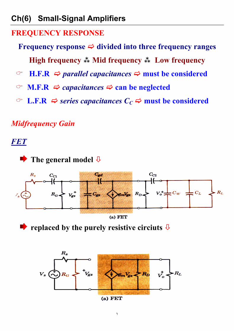
Midfrequency Gain FET
The general model
replaced by the purely resistive circiuts

Ch(6) Small-Signal Amplifiers
٢

Ch(6) Small-Signal Amplifiers
٣
BJT
For stability RB << β RE
RB >> rπ
The ideal condition
The circuit stable and simple to analyze

Ch(6) Small-Signal Amplifiers
٤
Low-Frequency Response
Below the midfrequencies
The susceptances of the parallel capacitors neglibly small
The reactance of the coupling capacitance increasliy
important

Ch(6) Small-Signal Amplifiers
٥
Coupling Capacitors
The general model reduced to simpler low frequency model
RG retained significant
RB omitted large compared to rπ
FET BJT models are analogous one analysis serve
for both
The general circuit (a) replaced by
Thevenin form input circuit
OR
Norton form output circuit

Ch(6) Small-Signal Amplifiers
٦
The two forms are equivalents CC effectively shorted
The output of Thevenin circuit
The low-frequency output VL related to the midfrequency
output by complex factor dependent on
frequency RC product
As frequency decreased large fraction of VT
appears across CC V at the output reduced
The cutoff half - power frequency
Defined by

Ch(6) Small-Signal Amplifiers
٧
The behavior of FET BJT predicted at low-
frequency
The input voltage Vgs Vbe down to 70% of Vo at
The output voltage Vo down to 70% of gm Vgs Ro gm
Vbe Ro the corresponding amplifier gain reduced
The overall low-frequency voltage gain for
FET
The relative gain for BJT OR FET

Ch(6) Small-Signal Amplifiers
٨
To predict the behavior of a given circuit determine
ω11 ω12 the higher is
To design a circuit calculate
CC1 CC2
H-W P.P 14-3