ch19 springs
TRANSCRIPT

8/13/2019 CH19 Springs
http://slidepdf.com/reader/full/ch19-springs 1/24
Chapter 19
Springs
8/13/2019 CH19 Springs
http://slidepdf.com/reader/full/ch19-springs 2/24
Chapter 19: Springs
Springs Characterized By:
Ability to deform significantly without
failure Ability to store/release PE over large
deflections
Provides an elastic force for useful purpose
8/13/2019 CH19 Springs
http://slidepdf.com/reader/full/ch19-springs 3/24
Chapter 19: Springs
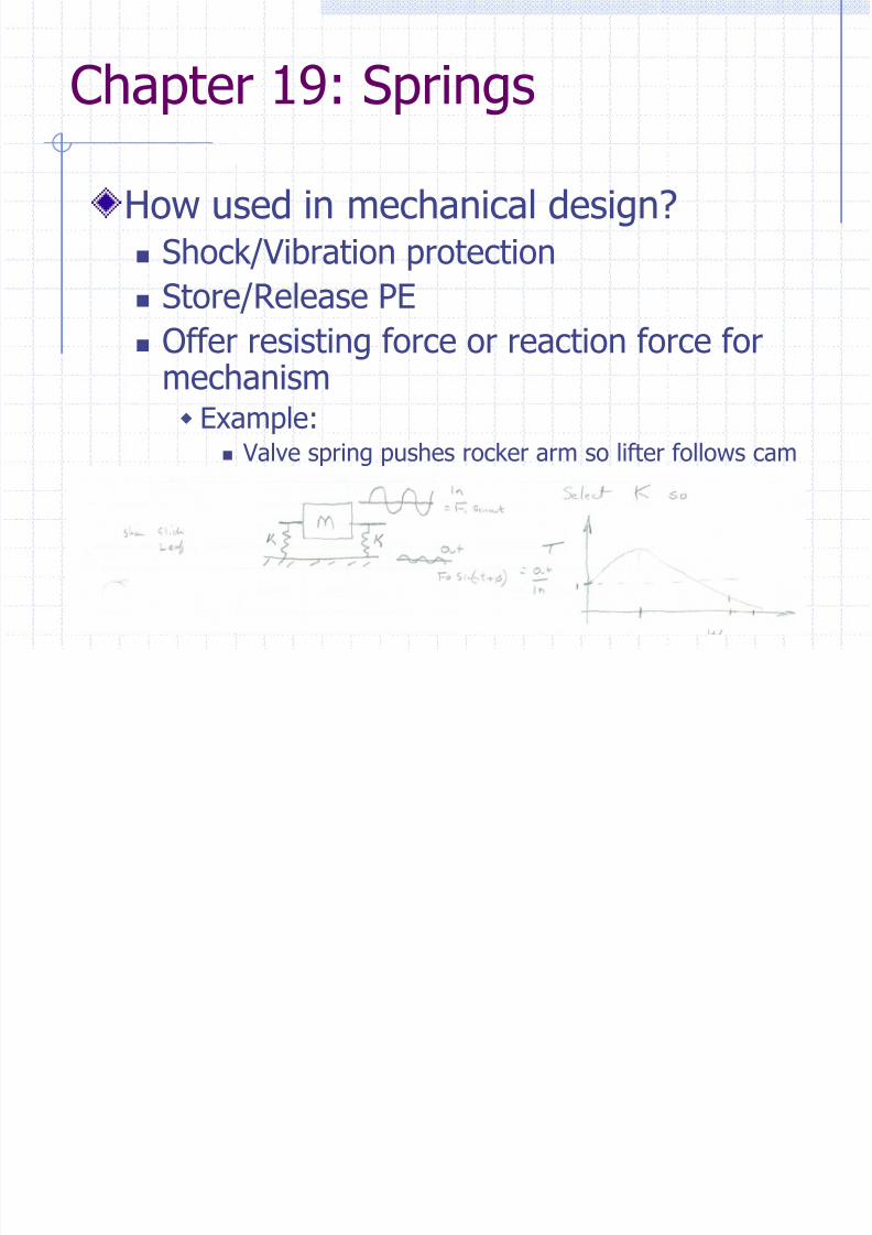
How used in mechanical design? Shock/Vibration protection
Store/Release PE Offer resisting force or reaction force for
mechanism Example:
Valve spring pushes rocker arm so lifter follows cam VCR lid – torsion springs keeps door closed
8/13/2019 CH19 Springs
http://slidepdf.com/reader/full/ch19-springs 4/24
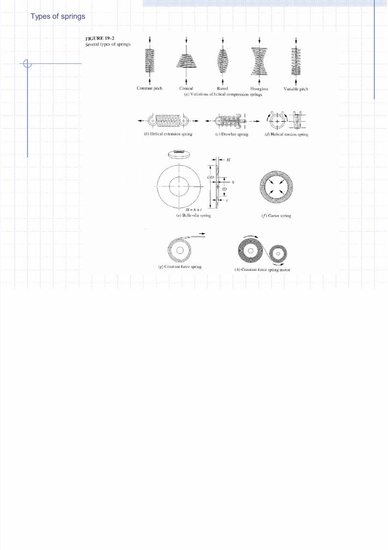
Types of springs
8/13/2019 CH19 Springs
http://slidepdf.com/reader/full/ch19-springs 5/24
Chapter 19: Springs
Our focus will be on Helical CompressionSprings
Standard round wire wrapped into cylinder,usually constant pitch
We will cover design process and analysis
8/13/2019 CH19 Springs
http://slidepdf.com/reader/full/ch19-springs 6/24
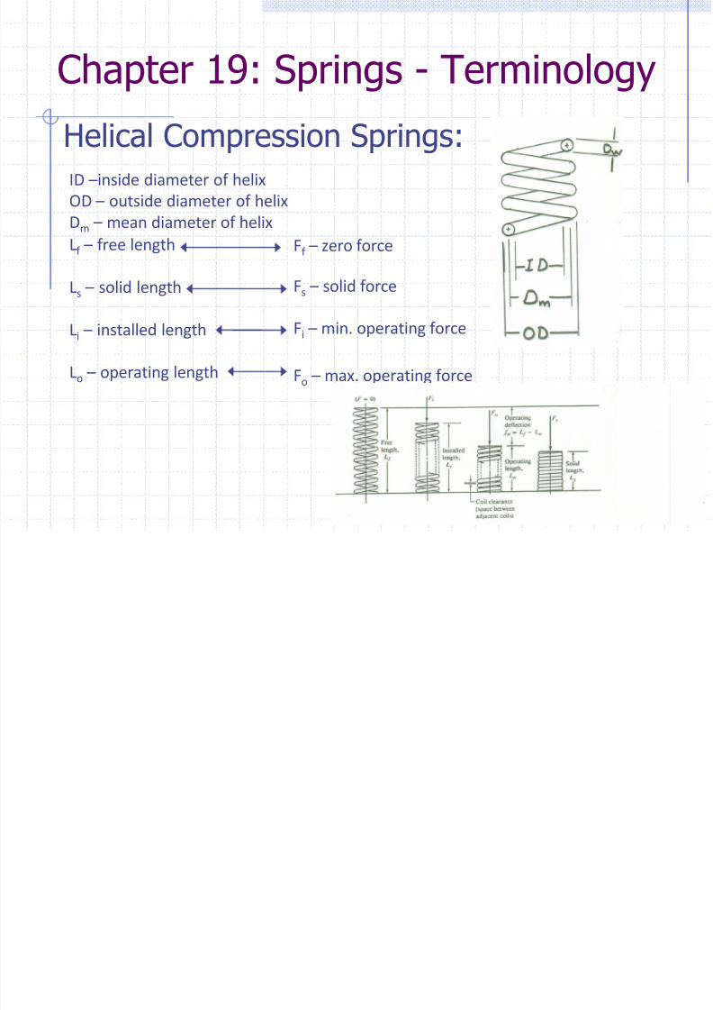
Chapter 19: Springs - Terminology
Helical Compression Springs:ID –inside diameter of helix
OD – outside diameter of helix
Dm – mean diameter of helix
Lf – free length
Ls – solid length
Li – installed length
Lo – operating length
Ff – zero force
Fs – solid force
Fi – min. operating force
Fo – max. operating force
8/13/2019 CH19 Springs
http://slidepdf.com/reader/full/ch19-springs 7/24
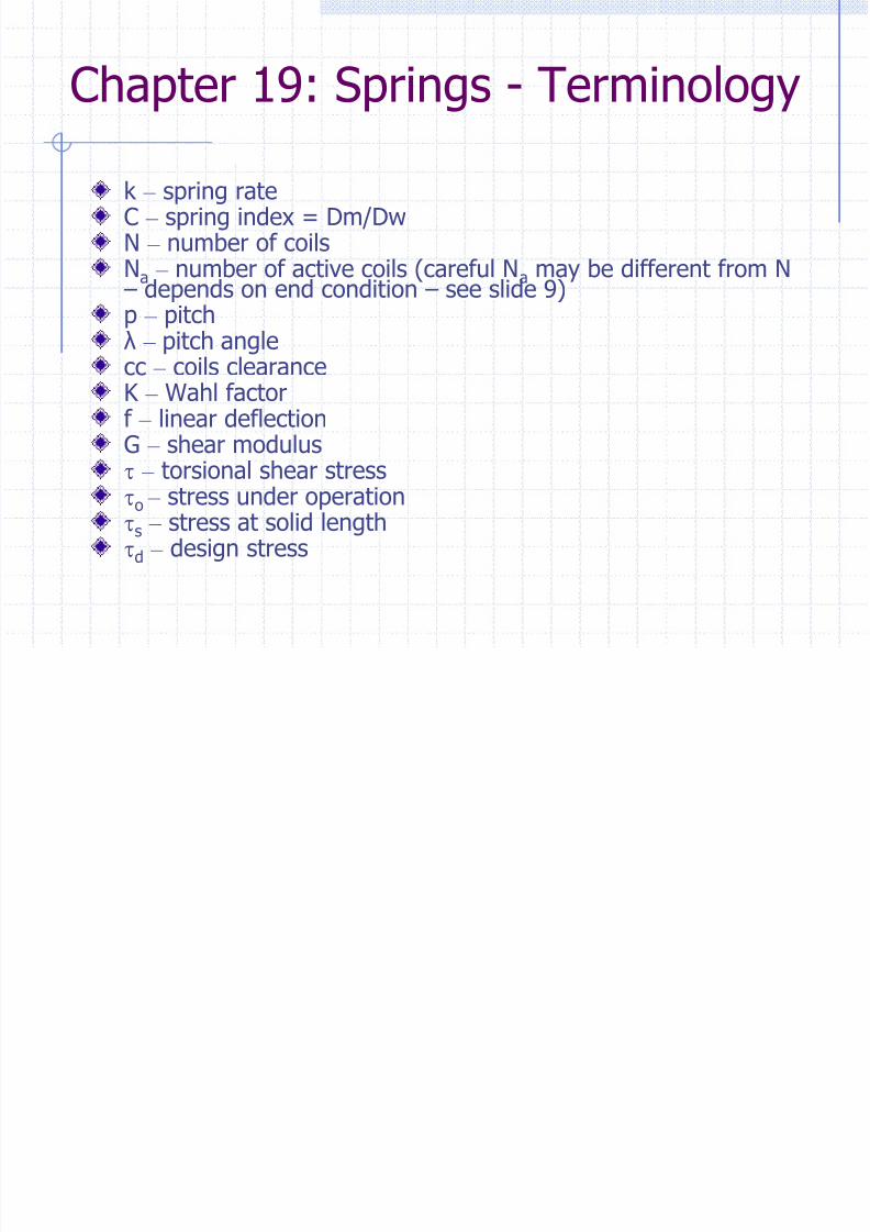
k – spring rateC – spring index = Dm/DwN – number of coilsNa – number of active coils (careful Na may be different from N – depends on end condition – see slide 9)p –
pitchλ – pitch anglecc – coils clearanceK – Wahl factorf – linear deflection
G –
shear modulust – torsional shear stressto – stress under operation
ts – stress at solid length
td – design stress
Chapter 19: Springs - Terminology
8/13/2019 CH19 Springs
http://slidepdf.com/reader/full/ch19-springs 8/24
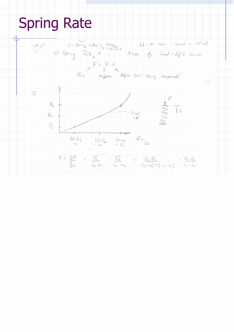
Spring Rate

8/13/2019 CH19 Springs
http://slidepdf.com/reader/full/ch19-springs 9/24
Chapter 19: Springs
8/13/2019 CH19 Springs
http://slidepdf.com/reader/full/ch19-springs 10/24
8/13/2019 CH19 Springs
http://slidepdf.com/reader/full/ch19-springs 11/24
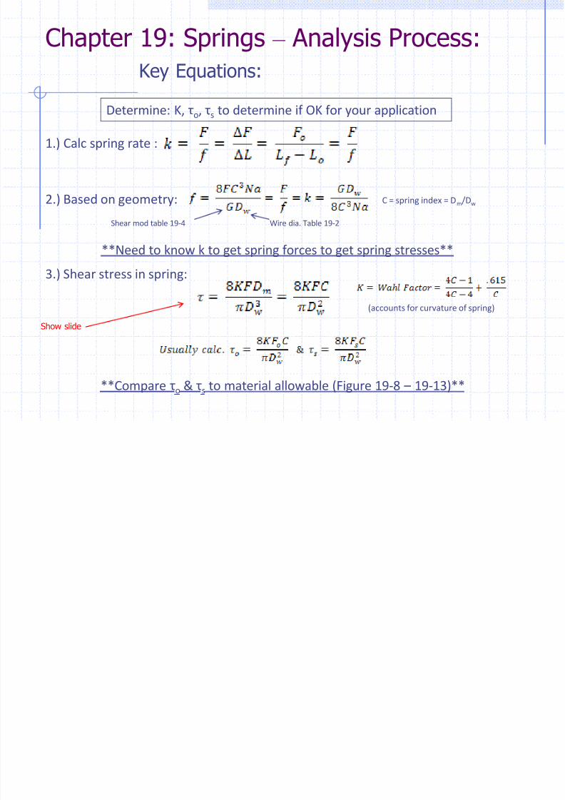
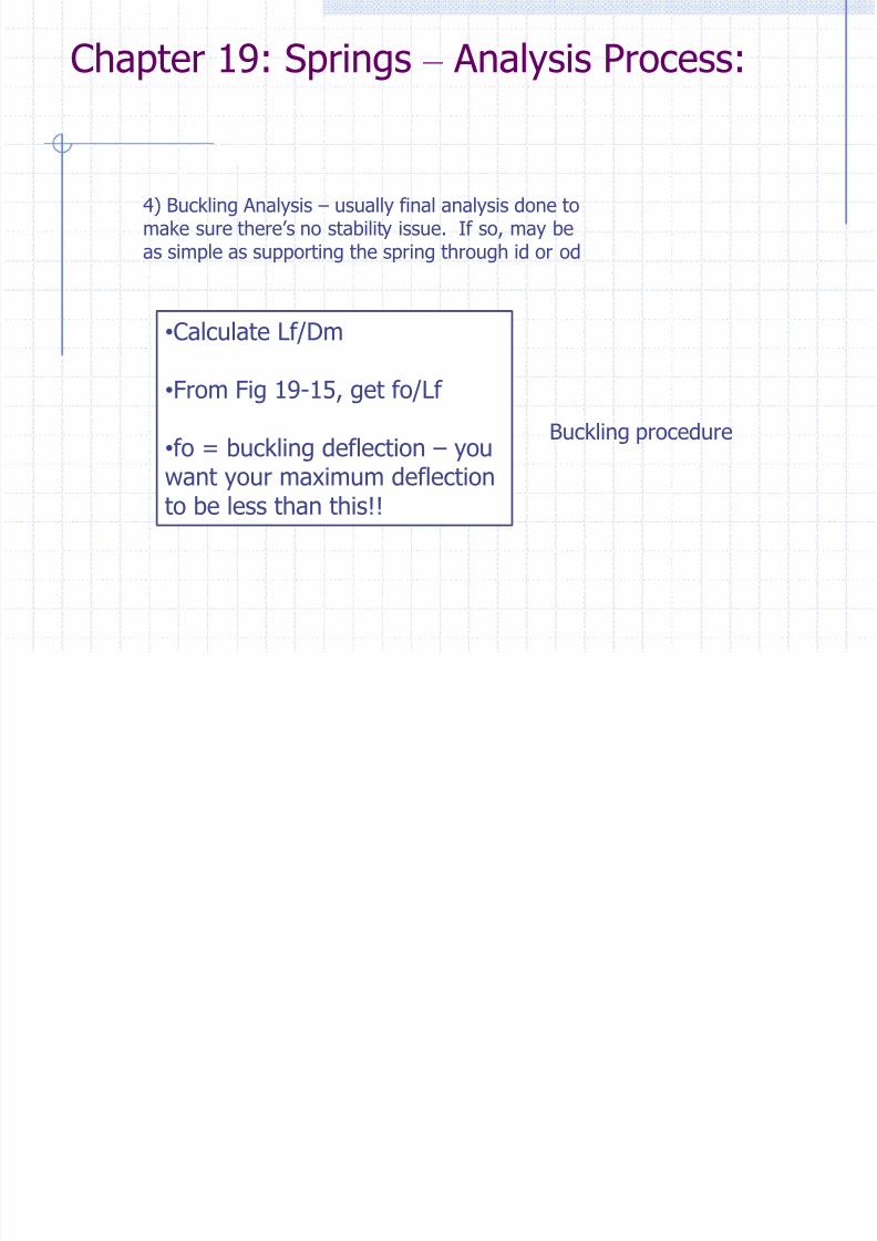
Chapter 19: Springs – Analysis Process:
4) Buckling Analysis – usually final analysis done tomake sure there’s no stability issue. If so, may beas simple as supporting the spring through id or od
•Calculate Lf/Dm
•From Fig 19-15, get fo/Lf
•fo = buckling deflection – youwant your maximum deflectionto be less than this!!
Buckling procedure
8/13/2019 CH19 Springs
http://slidepdf.com/reader/full/ch19-springs 12/24
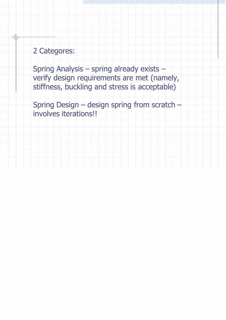
2 Categores:
Spring Analysis – spring already exists –
verify design requirements are met (namely,stiffness, buckling and stress is acceptable)
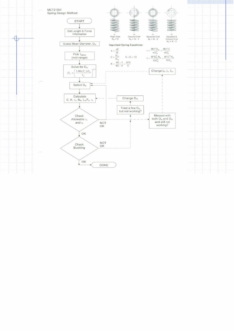
Spring Design – design spring from scratch – involves iterations!!
8/13/2019 CH19 Springs
http://slidepdf.com/reader/full/ch19-springs 13/24
8/13/2019 CH19 Springs
http://slidepdf.com/reader/full/ch19-springs 14/24
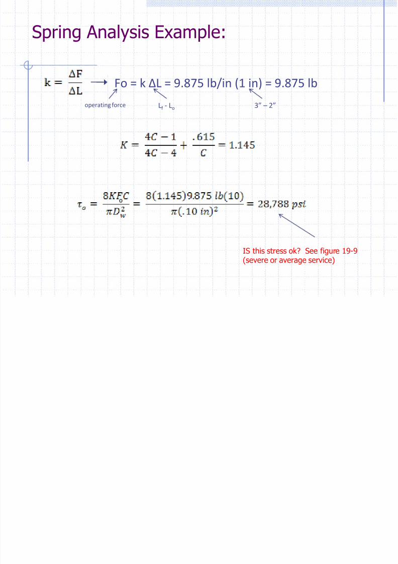
Fo = k ΔL = 9.875 lb/in (1 in) = 9.875 lb
operating force Lf - Lo 3” – 2”
IS this stress ok? See figure 19-9(severe or average service)
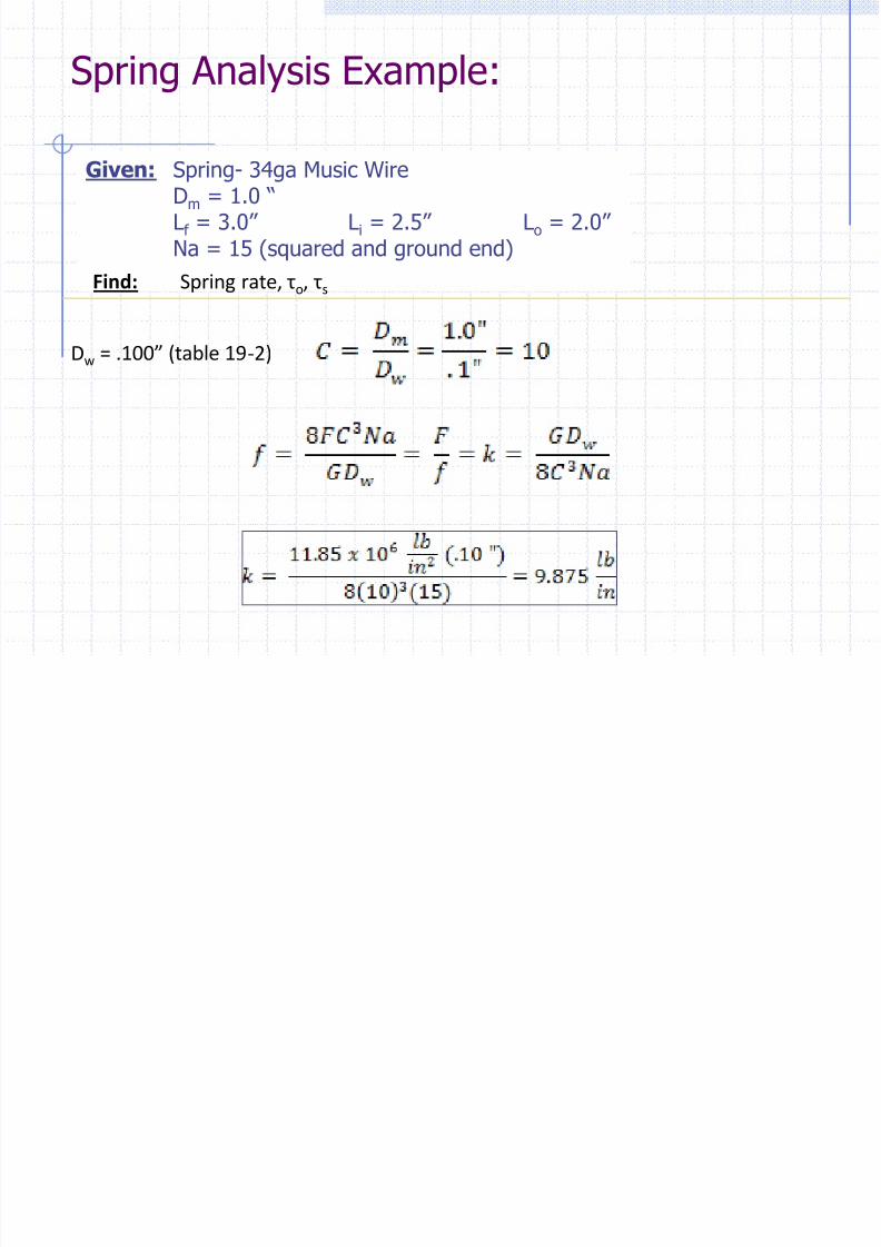
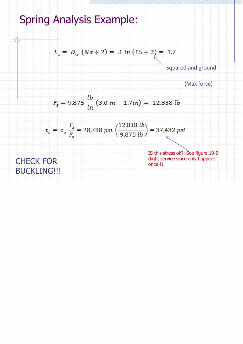
Spring Analysis Example:
o
8/13/2019 CH19 Springs
http://slidepdf.com/reader/full/ch19-springs 15/24
Squared and ground
(Max force)
Spring Analysis Example:
IS this stress ok? See figure 19-9(light service since only happensonce!!)CHECK FOR
BUCKLING!!!
8/13/2019 CH19 Springs
http://slidepdf.com/reader/full/ch19-springs 16/24
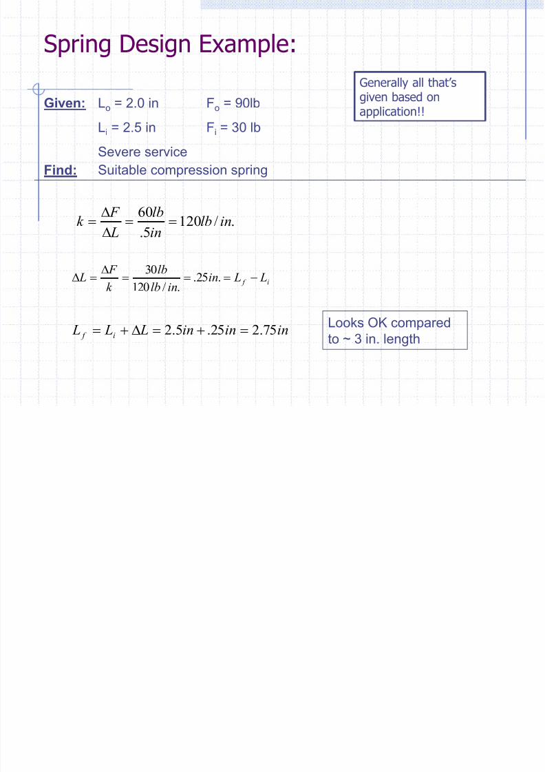
Given: Lo = 2.0 in Fo = 90lb
Li = 2.5 in Fi = 30 lb
Severe service
Find: Suitable compression spring
./1205.
60inlb
in
lb
L
F k
i f L Lininlb
lb
k
F L
.25.
./120
30
ininin L L L i f 75.225.5.2 Looks OK compared
to ~ 3 in. length
Spring Design Example:
Generally all that’s
given based onapplication!!
8/13/2019 CH19 Springs
http://slidepdf.com/reader/full/ch19-springs 17/24
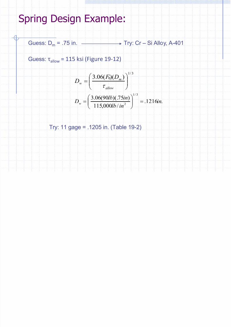
Guess: Dm = .75 in. Try: Cr – Si Alloy, A-401
Guess: τallow = 115 ksi (Figure 19-12)
3/1
))((06.3
allow
mw
D F D
t
.1216./000,115
)75)(.90(06.3 3/1
2 in
inlb
inlb Dw
Try: 11 gage = .1205 in. (Table 19-2)
Spring Design Example:
o
8/13/2019 CH19 Springs
http://slidepdf.com/reader/full/ch19-springs 18/24
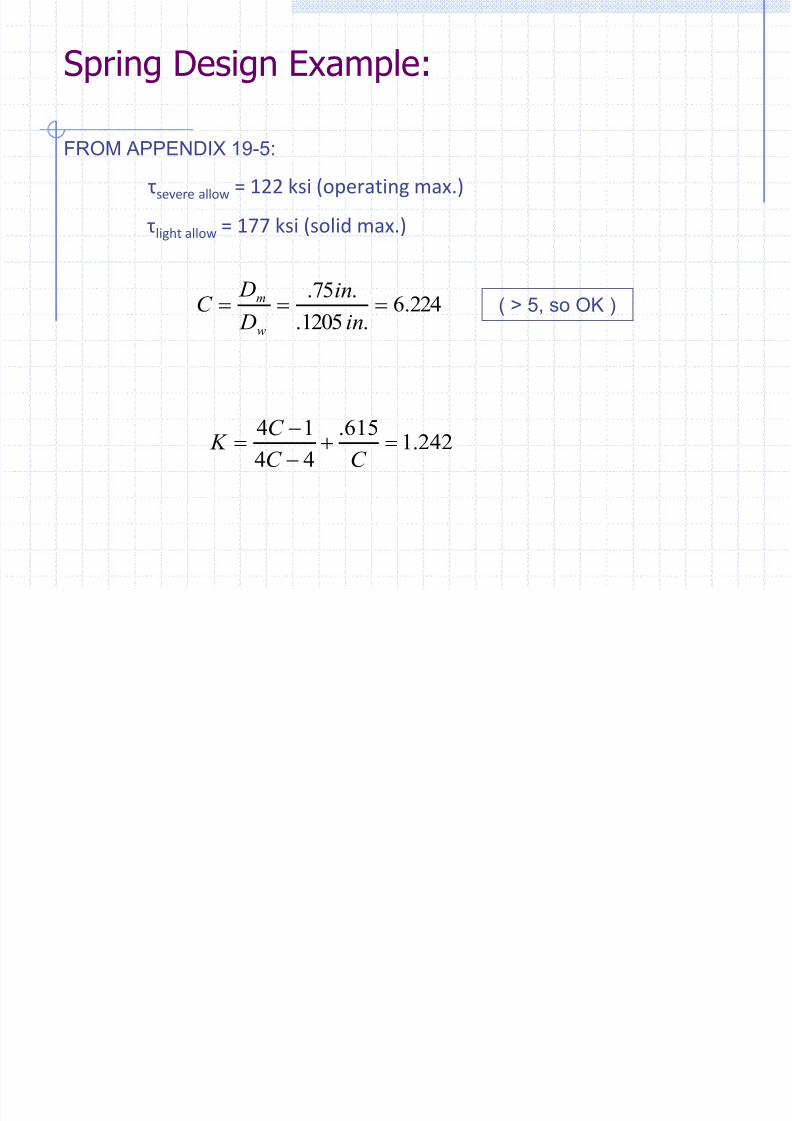
FROM APPENDIX 19-5:
τsevere allow = 122 ksi (operating max.)
τlight allow = 177 ksi (solid max.)
224.6.1205.
.75.
in
in
D
DC
w
m
242.1615.
44
14
C C
C K
( > 5, so OK )
Spring Design Example:
8/13/2019 CH19 Springs
http://slidepdf.com/reader/full/ch19-springs 19/24
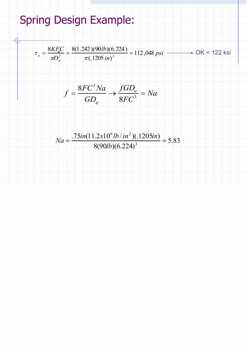
psiin
lb
D
KFC
w
o 048,112)1205(.
)224.6)(90)(242.1(8822
t OK < 122 ksi
Na FC
fGD
GD
Na FC f w
q
3
3
8
8
83.5)224.6)(90(8
)1205)(./102.11(75.3
26
lb
ininlb xin Na
Spring Design Example:
o
8/13/2019 CH19 Springs
http://slidepdf.com/reader/full/ch19-springs 20/24
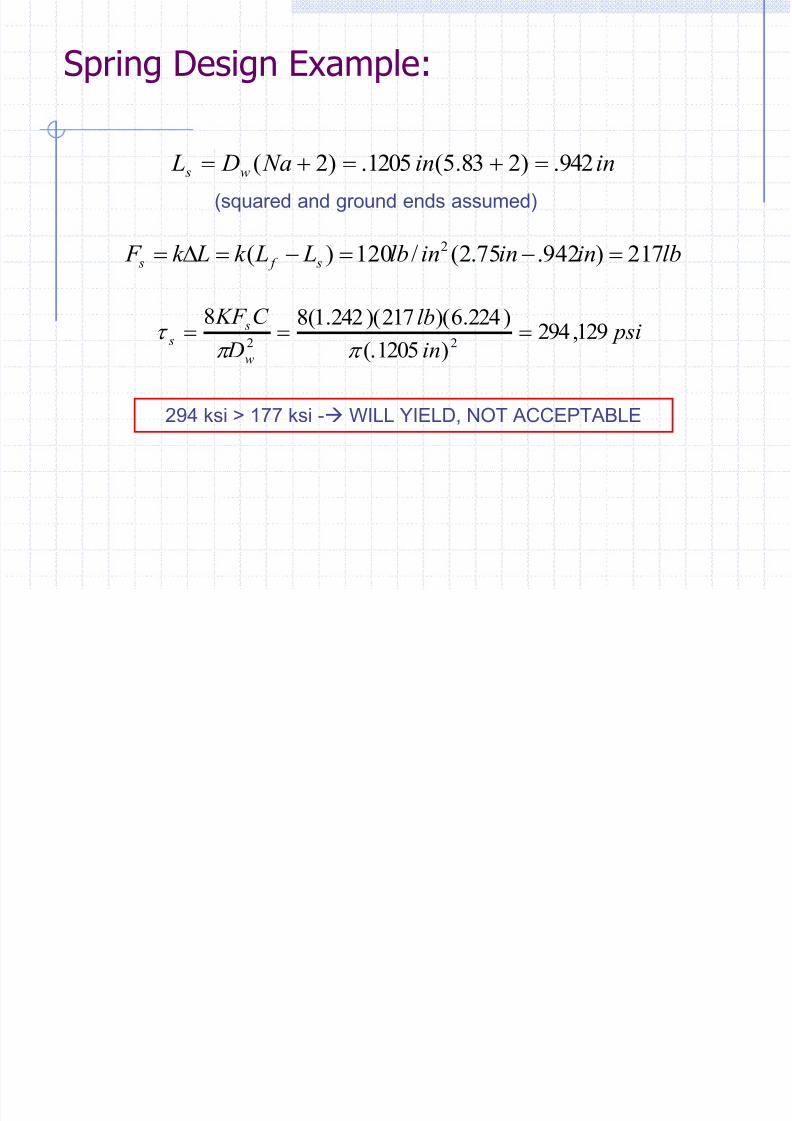
inin Na D L w s 942.)283.5(1205.)2(
(squared and ground ends assumed)
lbinininlb L Lk Lk F s f s 217)942.75.2(/120)( 2
psiin
lb
D
C KF
w
s s 129,294
)1205(.
)224.6)(217)(242.1(8822
t
294 ksi > 177 ksi - WILL YIELD, NOT ACCEPTABLE
Spring Design Example:
8/13/2019 CH19 Springs
http://slidepdf.com/reader/full/ch19-springs 21/24
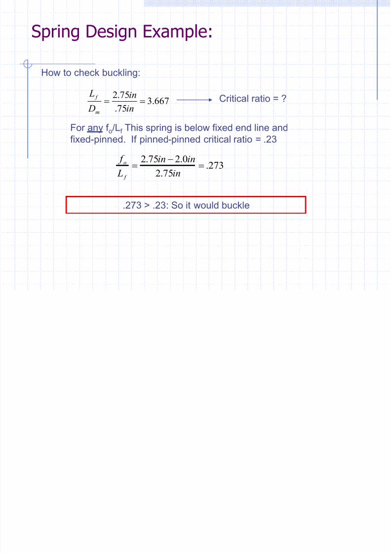
How to check buckling:
667.375.
75.2
in
in
D
L
m
f Critical ratio = ?
For any f o/Lf This spring is below fixed end line and
fixed-pinned. If pinned-pinned critical ratio = .23
273.75.2
0.275.2
in
inin
L
f
f
o
.273 > .23: So it would buckle
Spring Design Example:
8/13/2019 CH19 Springs
http://slidepdf.com/reader/full/ch19-springs 22/24
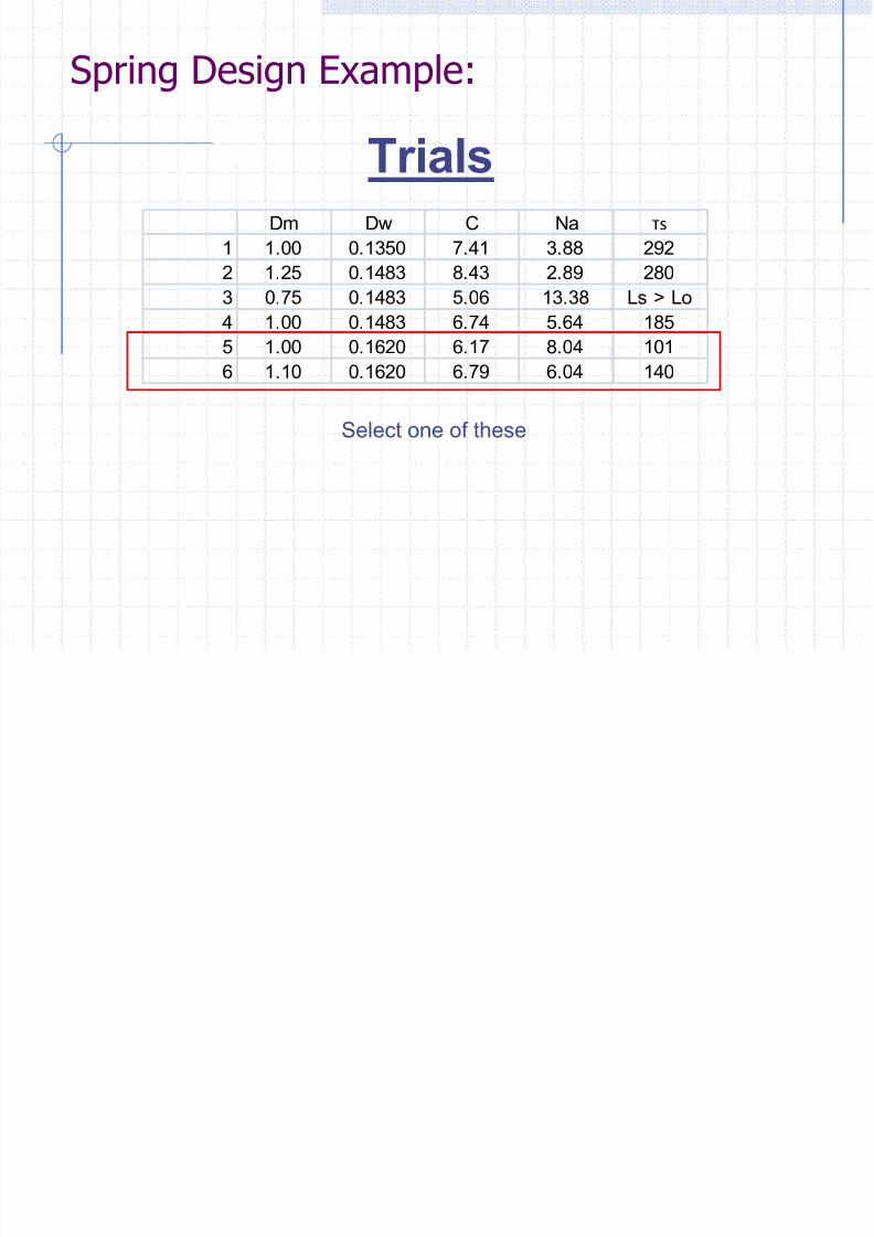
TrialsDm Dw C Na τs
1 1.00 0.1350 7.41 3.88 292
2 1.25 0.1483 8.43 2.89 280
3 0.75 0.1483 5.06 13.38 Ls > Lo
4 1.00 0.1483 6.74 5.64 185
5 1.00 0.1620 6.17 8.04 101
6 1.10 0.1620 6.79 6.04 140
Select one of these
Spring Design Example:

8/13/2019 CH19 Springs
http://slidepdf.com/reader/full/ch19-springs 23/24
But…. Τallow and K depend on Dw
So……Guess K is mid-range, about 1.2
Then:
Side Info: How determine initial estimate for Dw
3
8
w
m
D
KFD
t Equation for shear stress
where geometry is known
Re-arrange….
3/1
0 ))((06.3
allow
m
w
D F D
t
06.3)2.1(88
K
This Dw is about where to start for spring design. Both K and τallow
may be found for selected Dw.
8/13/2019 CH19 Springs
http://slidepdf.com/reader/full/ch19-springs 24/24