ch 5 : multimedia network standardization, qos , access media
DESCRIPTION
Ch 5 : Multimedia Network Standardization, QoS , Access Media. Science and Technology Faculty Informatics. Arini, ST, MT arinizul@gmail. Com [email protected]. Contents. Multimedia Presentation Charactersitic of Multimedia Application Networked Multimedia Classification - PowerPoint PPT PresentationTRANSCRIPT

Ch 5 : Multimedia Network Standardization, QoS, Access
Media
Science and Technology Faculty
Informatics
Arini, ST, MTarinizul@gmail. [email protected]

Contents
• Multimedia Presentation• Charactersitic of Multimedia Application• Networked Multimedia Classification• Multimedia Networked
– Consideration of Networked Multimedia– Standardizations– QoS
• Metrics
• Media Access

I. Multimedia Presentation
• Local vs Networked multimedia– Local Multimedia :
• Storage and presentation of multimedia information in standalone computers
– Networked Multimedia • Involve transmission and distribution of multimedia
information on the network (wired and wireless)

II. Networked Multimedia Classification
• Real Time: – Require bounds on end-to-end packet delay & jitter. – Subdivided into:
• Discrete Media: MSN/Yahoo Messenger• Continuous Media: Continuous message stream
with inter-message dependency. Further divided into:
– Delay Tolerant (called : streaming) e.g Internet webcast
– Delay Intolerant (called : interactive) e.g. audio, video streams in conferencing systems
• Non-Real Time: – No strict delay constraints (e.g. text, image files)– May be highly sensitive to errors

5
• Streaming : – Live media transmission system (live
broadcasting)– Send stored media across the network (On
Demand file)
• Hybrid (Progressive Download) : interactive
II. Networked Multimedia Classification
6
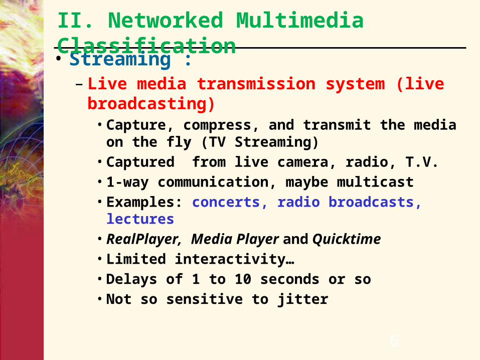
• Streaming : – Live media transmission system (live
broadcasting)• Capture, compress, and transmit the media on
the fly (TV Streaming)• Captured” from live camera, radio, T.V.• 1-way communication, maybe multicast• Examples: concerts, radio broadcasts, lectures• RealPlayer, Media Player and Quicktime• Limited interactivity…• Delays of 1 to 10 seconds or so• Not so sensitive to jitter
II. Networked Multimedia Classification

7
• Streaming : – Live media transmission system (live broadcasting)– Send stored media across the network (On Demand
file)• Media is pre-compressed and stored at the server. • This system delivers the stored media to one or
multiple receivers (video conferencing, Youtube)• Examples: pre-recorded songs, video-on-demand• RealPlayer, Media Player and Quicktime• Interactivity, includes pause, ff, rewind…• Delays of 1 to 10 seconds or so• Not so sensitive to jitter
II. Networked Multimedia Classification

8
• Streaming : – Live media transmission system (live broadcasting)– Send stored media across the network (On Demand
file)
• Hybrid (Progressive Download) : (called : interactive)– 2-way communication– Examples: Internet phone, video conference– Very sensitive to delay
< 150ms very good
< 400ms ok
> 400ms crappy
II. Networked Multimedia Classification

II. Networked Multimedia Classification

Digital Media: from desktop, to Internet, to hand-helds, to wireless, and to Peer-to-Peer
Edge server
Edge server
Data Farms / Storage
Web ServerApps/DB Server
E-Commerce Server
Media Server
Wireless Comm Server

III. Characteristics of multimedia Application
• Interactive, High Performance, Enriched Media, Large data volume, Real-time property (Continuous display).
• How to transmit across network?– Properties of current Internet
• Best effort network, cannot guarantee quality of multimedia applications
• Limitation of bandwidth• Heterogeneity
– Different user requirements– Different user network conditions
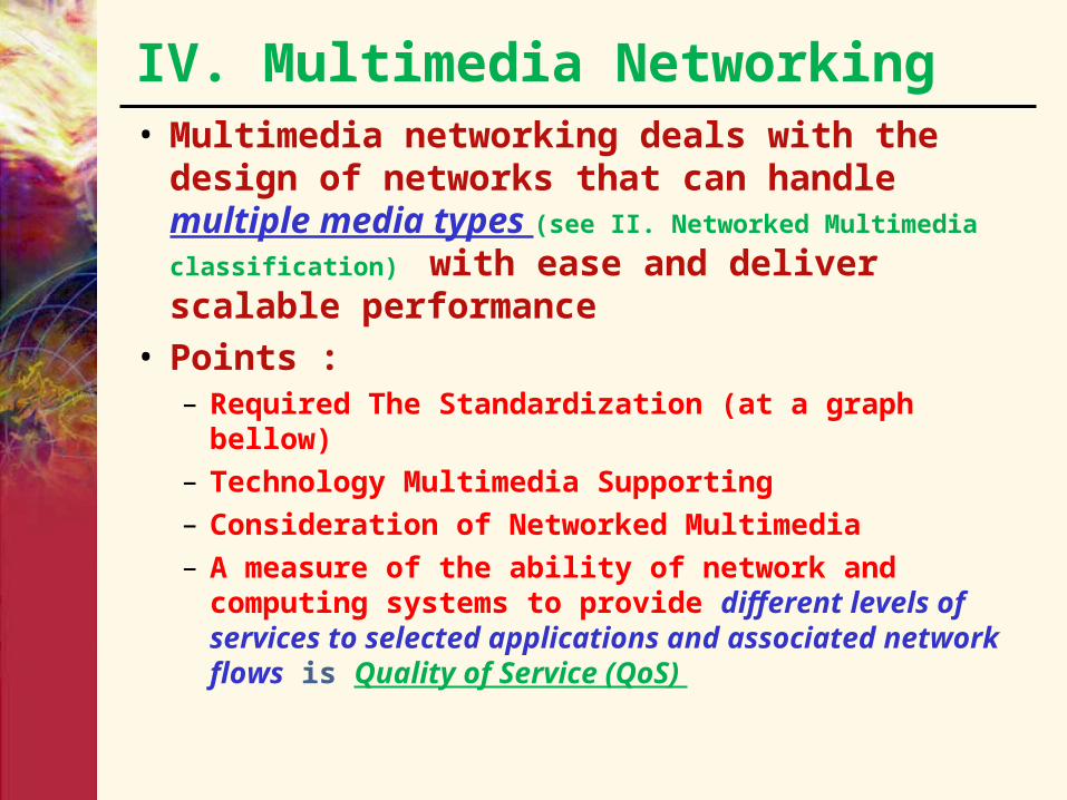
IV. Multimedia Networking• Multimedia networking deals with the
design of networks that can handle multiple media types (see II. Networked Multimedia classification)
with ease and deliver scalable performance• Points :
– Required The Standardization (at a graph bellow)
– Technology Multimedia Supporting
– Consideration of Networked Multimedia
– A measure of the ability of network and computing systems to provide different levels of services to selected applications and associated network flows is Quality of Service (QoS)
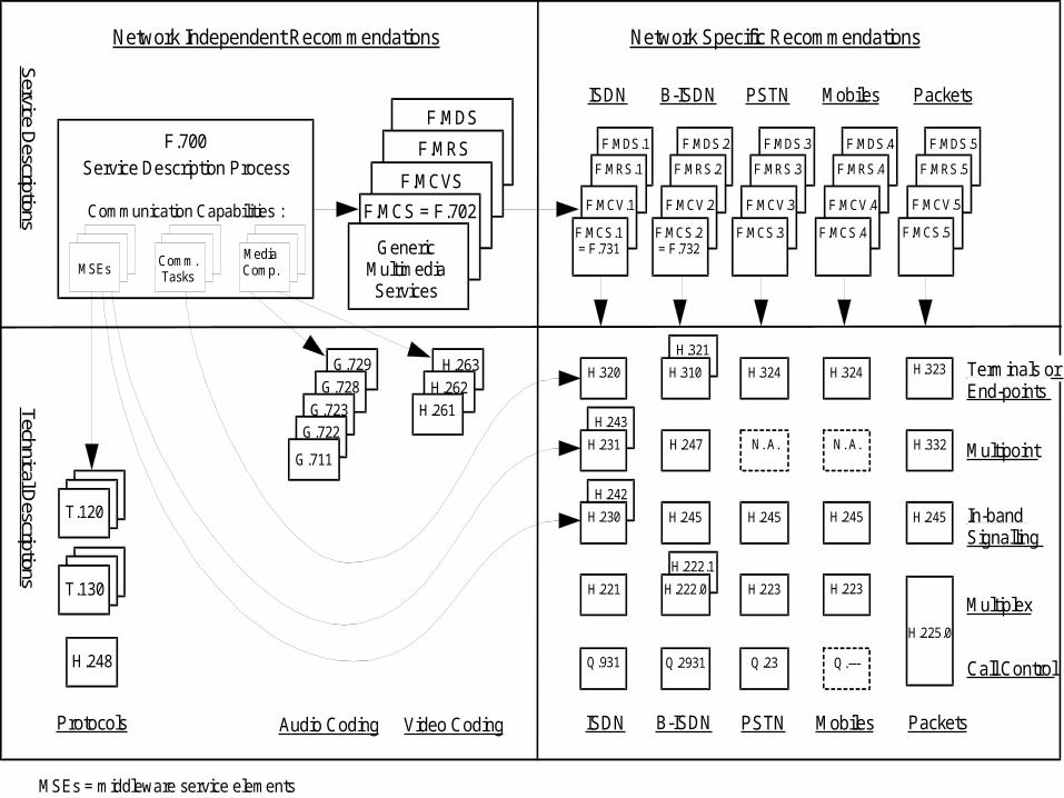
F.MDS
Service D
escriptionsTechnical D
escriptions
T.130
H.263
H.262H.261
H.243
H.231
H.320
H.242
H.230
H.221
Q.931
ISDN
ISDN
F.MCS.1 = F.731
F.MCV.1
F.MRS.1
F.MDS.1
N. A.
H.324
H.245
H.223
Q.23
PSTN
PSTN
F.MCS.3
F.MCV.3
F.MRS.3
F.MDS.3
N. A.
H.324
H.245
H.223
F.MCS.4
F.MCV.4
F.MRS.4
F.MDS.4
Q.---
Mobiles
Mobiles
Terminals or End-points
Multipoint
In-band Signalling
Multiplex
Call Control
B-ISDN
B-ISDN
H.247
H.321
H.310
H.245
H.222.1
H.222.0
Q.2931
F.MCS.2 = F.732
F.MCV.2
F.MRS.2
F.MDS.2
Network Independent Recommendations Network Specific Recommendations
Video CodingAudio CodingProtocols
G.729
G.728
G.723G.722
Communication Capabilities :
F.700Service Description Process
F.MRS
F.MCVS
F.MCS = F.702
Generic Multimedia Services
H.332
H.323
H.245
H.225.0
Packets
Packets
F.MCS.5
F.MCV.5
F.MRS.5
F.MDS.5
G.711
Media Comp.
Comm. Tasks
MSEs
MSEs = middleware service elements
T.120
H.248
14
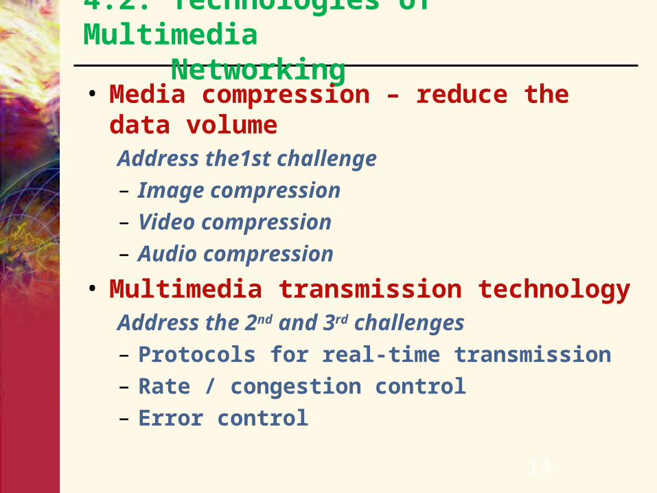
4.2. Technologies of Multimedia Networking• Media compression – reduce the data
volumeAddress the1st challenge– Image compression– Video compression– Audio compression
• Multimedia transmission technologyAddress the 2nd and 3rd challenges– Protocols for real-time transmission– Rate / congestion control – Error control
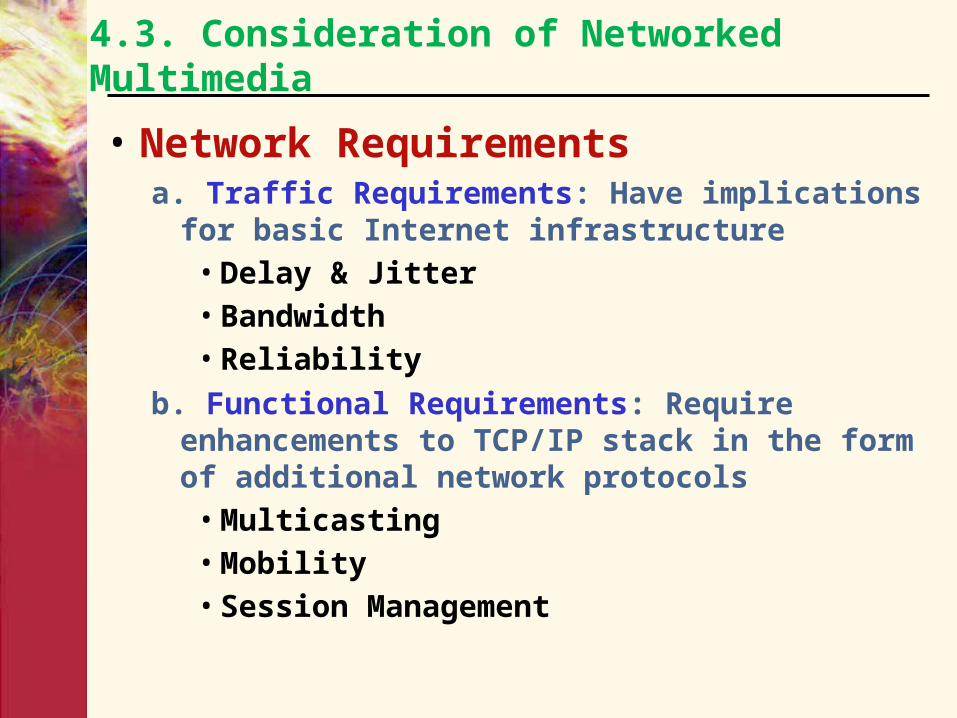
4.3. Consideration of Networked Multimedia
• Network Requirementsa. Traffic Requirements: Have implications for
basic Internet infrastructure• Delay & Jitter• Bandwidth• Reliability
b. Functional Requirements: Require enhancements to TCP/IP stack in the form of additional network protocols
• Multicasting• Mobility• Session Management

4.3. Consideration of Networked Multimedia
• Requirements– Delay & Jitter
• Metrics• Packet Processing delay• Packet Transmission delay• Propagation delay• Routing and Queuing Delay
– Bandwidth– Reliability– Multicasting– Session Management– Security– Mobility

4.3.1. Delay
• Related Metrics– Maximum end to end delay– Delay variance
• Jitter : non-monotonic variation in delay in given stream
– For a video stream jitter would result in a shaky picture
– Jitter can be removed by buffering at the receiver side
• Skew: constantly increasing difference between the expected arrival time and the actual arrival time
– For a video stream skew could be a slower or faster moving picture
4.3.1. Delay
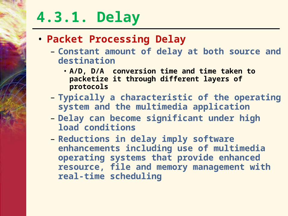
• Packet Processing Delay– Constant amount of delay at both source and
destination• A/D, D/A conversion time and time taken to packetize
it through different layers of protocols
– Typically a characteristic of the operating system and the multimedia application
– Delay can become significant under high load conditions
– Reductions in delay imply software enhancements including use of multimedia operating systems that provide enhanced resource, file and memory management with real-time scheduling

4.3.1. Delay
• Packet Transmission Delay– Time taken by the physical layer at the
source to transmit packets. Depends on• Number of active sessions. Typically physical
layer processes packets in FIFO order. Delay can become significant if OS does not support real-time scheduling for multimedia traffic
• MAC access delay: Widespread Ethernet networks cannot provide any firm guarantees on medium access delay due to inherent indeterminism in CSMA/CD (carrier sense multiple access/collision detection). Isochronous Ethernet (802.9) integrated voice data LAN and demand priority Ethernet (802.12) provide QoS but market potential remains low

4.3.1. Delay
• Propagation Delay– Flight time of packets – limited by speed
of light. Can’t do anything about it– For a distance of 20,000 km this would be
about 0.067 sec– Significant part of a desirable ~200 msec
delay budget
4.3.1. Delay
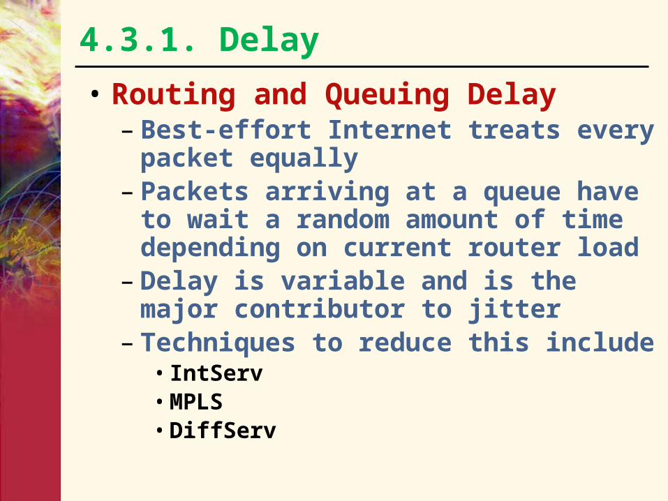
• Routing and Queuing Delay– Best-effort Internet treats every packet
equally– Packets arriving at a queue have to wait a
random amount of time depending on current router load
– Delay is variable and is the major contributor to jitter
– Techniques to reduce this include• IntServ• MPLS• DiffServ
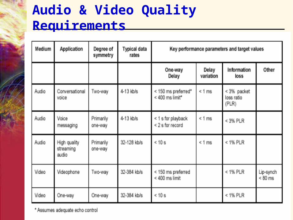
Audio & Video Quality Requirements
4.3.2. Bandwidth Requirements• Multimedia traffic streams have high bandwidth• Uncontrolled transmissions at high rates can cause
heavy congestion in the network• Elastic applications that use TCP take advantage of
built in congestion control• Most multimedia applications use UDP for transmitting
media streams• To remove these shortcomings an enhanced internet
service model would require– Admission control: application must first get permission
from some authority to send traffic at a given rate with given traffic characteristics
– Bandwidth reservation: if admission is given, appropriate resources (buffers, bandwidth) will get reserved along the path
– Traffic policing mechanisms: to ensure that applications do not send data at a rate higher than what was negotiated

APPLICATION
PERFORMANCE DIMENSIONS
BandwidthSensitivity to
Delay Jitter Loss
IP Telephony Low High High Med
Video Conferencing High High High Med
Streaming media Low-High Med Low Med
Client / Server Transactions Low Med Low High1
Email (store/forward) Low Low Low High1
Best Effort Traffic Low-Med Low Low Low
Bandwidth
• Text– Bandwidth requirements depend on
size• Can be easily reduced by compression
techniques
– Some text applications require complete freedom from loss & errors – use TCP. E.g. FTP
– Others are error and loss tolerant – use UDP e.g. instant messaging

Bandwidth
• Audio– Bandwidth requirements depend on dynamic
range and/or spectrum• Narrowband speech (300-3300Hz)
– 6.4 Kbps (G.723.3) to 64 Kbps (G.711)• Wideband audio (CD quality music) 10-220 KHz
– 112-128 Kbps (MP3)
– Can tolerate 1-2% packet loss– Real-time nature depends on extent of
interactivity• VoIP requires strong bounds on delay/jitter (Real-Time
Intolerant)
– < 250 ms end to end delay• Internet Webcast is more delay/jitter tolerant (Real-Time
Tolerant)

Bandwidth
• Video– High bandwidth requirements– Efficient compression schemes
• MPEG-I (1.2 Mbps) VCR quality compression• MPEG-II (3-100 Mbps) broadcast quality video,
HDTV• MPEG-IV (64 Kbps) for low bandwidth video
compression; supports audio, video, graphics, animation, text
• H.261 (px64 Kbps) • H.263 (18-64 Kbps)
– Error requirements and real-time characteristics similar to audio

Bandwidth
• Graphics and Animation– Examples: Digital images, flash presentations– Large in size but lend themselves well to
compression– Progressive compression techniques enable
image to be initially displayed in low-quality and gradually improved as more information is received
– Error-tolerant and can sustain packet loss provided application knows how to deal with packet loss
– No real-time constraints

4.3.3. Reliability• Pertains to loss and corruption of data• Can be measured in terms of loss probability• Requires methods for dealing with
erroneous/lost data– Error correction
• Sender Based Repair– Active : ARQ
– Passive : Interleaving, FEC
• Error Concealment
– Error Recovery for Different Applications
– Admission Control
– Traffic Shaping/Policing
– Packet Classification
– Packet Dropping

a. Error Correction
• Sender Based Repair– Active Repair - Automatic retransmission
request (ARQ)• Suitable for error intolerant applications
– Passive Repair• Interleaving• FEC: Forward Error Correction.
– Media Independent – independent of the content/nature of the stream
– Media Dependent - use knowledge of the stream in the repair process
• Error Concealment (Receiver Based Repair)
Passive Repair : Interleaving• Can be used when media unit size is smaller than packet size (as
may be the case with audio) and end-to-end delay is not important
• Units are resequenced before transmission so that originally adjacent units are separated by a guaranteed distance and returned to original order at the receiver
• Disperses the effect of packet loss – loss of a single packet would causes multiple smaller gaps among original media units
• In case of audio a phoneme originally encapsulated in one packet would get split across multiple packets
• Loss of small parts of several phonemes is easier to deal with than loss of entire phonemes
• Disadvantage: increased latency – not well suited for interactive applications
• Advantage: does not increase bandwidth usage – does well for non-interactive use
Passive Repair : FEC• Introduce repair data in traffic from which lost packets may be
recovered
• Media Independent: use block or algebraic codes to produce additional packets which aid in loss recovery
– Each code takes a codeword of k data packets and generates n-k additional check packets
– i-th bit in check packet is generated from the i-th bits of each associated data packet
• Parity Coding: XOR is applied across groups of packets to generate parity packets
• Reed-Solomon Coding: Based on properties of polynomials over particular number bases
– Take a set of codewords and use these as coefficients of a polynomial f(x)
– The transmitted codeword is determined by evaluating the polynomial for all nonzero values of x over the number base
– Disadvantage: Cause additional delay, increase bandwidth usage and exacerbate congestion

Passive Repair : Media Dependent FEC• Exploit media characteristics• For audio, could send each unit of audio in multiple packets
– Primary encoding: first transmission– Secondary encoding: additional transmissions– Secondary encoding could be of lower bandwidth and quality
than the primary coding– May not be necessary to transmit FEC for every packet due to
nature of media• Advantage : low latency – only single packet delay added
– Suitable for interactive applications
* A Survey of Packet Loss Recovery Techniques for Streaming Audio, Colin Perkins et al IEEE Network Sep/Oct 1998

Error Concealment
• Producing a replacement for a lost packet which is similar to the original
• Work for relatively small loss rates (< 15%) and for small packets (4-40 ms)
• Types in increasing order of computational cost and improved performance:– Insertion based: insert a fill-in packet that contains
silence, noise or a repitition of an adjacent packet
– Interpolation-based: some form of pattern matching and interpolation to derive the missing packet (waveform, pitch or timescale based)
– Regeneration-based: derive decoder state from packets surrounding the loss and generate a lost packet from that (model based recovery)

b. Error Recovery for Different Applications
• Non-interactive Applications – Multicasts (e.g. radio)
• Interleaving is suitable (bandwidth efficient, though high latency)
• Use error concealment – repetition with fading
• Media-independent FEC better than a retransmission based scheme
• Interactive Applications (e.g. IP telephony)– Media Dependent FEC– Error concealment using packet repetition

c. Admission Control
• Pro-active form of congestion control• Takes requested traffic description as input
including (in terms of leaky bucket parameters– Maximum burst size ( b = bucket size)– Peak rate – Average rate – Decides to accept or reject a flow including
consideration of impact to existing flows
• Admission control unit must also use measurements of current network load and packet delay in its admission decisions
d. Traffic Shaping/Policing
• Token bucket algorithm is used for traffic shaping.
• Limits the average rate and allows a degree of burstiness.– Token bucket depth ‘b’ in which tokens are
collected at rate ‘r’– When bucket becomes full extra tokens are
dropped– Source can send data only if it can grab and
destroy sufficient tokens from the bucket• Leaky bucket algorithm is used for traffic
policing, in which excessive traffic is dropped– Bucket depth ‘b’ with hole at the bottom– If bucket is full extra packets are dropped
e. Packet Classification
• In order to prevent all packets from being treated equally some mechanism to distinguish between real-time and non-real time packets is needed
• Done by packet marking e.g. use Type of Service (ToS) field in IP header
• MPLS uses short labels
f. Packet Scheduling
• FIFO scheduling traditionally used in routers needs to be replaced with more sophisticated queuing– Disadvantage: possible starvation of low
priority flows
• Weighted Fair Queuing has different queues for different classes. – However every queue is assigned a certain
weight. – Packets in that queue get a fraction of the total
bandwidth proportional to their weight
g. Packet Dropping
• Routers can randomly drop packets under congestion
• This can be a problem since certain packets may carry more information than others
4.3.4. Multicasting – IP Multicast• Can be done in several ways
• Send packets to multicast IP address (Class D)
• Hosts willing to receive multicast messages for particular multicast groups inform immediate-neighboring routers using IGMP
• Multicast routers exchange group information using a variety of algorithms:
– Flooding
– Spanning tree
– Reverse path broadcasting
– Reverse path multicasting
• Protocols that use some of these algorithms include– Distance Vector Muticast Routing Protocol (DVMRP)
– Multicast extension to Open Shortest Path First (MOSPF)
– Protocol Independent Multicast (PIM)

4.3.4. Multicasting – IP Multicast
• Application Layer Multicasting– SIP and H.323 support multicasting through a
multi-point control unit that provides mixing and conferencing functionality
4.3.5. Session Management • Media Description• Session Description Protocol• Session Announcement• Session Announcement Protocol• Session Control

4.3.5. Session Management • Media Description
– Enables application to distribute session information
• Media Type• Encoding Scheme• Session Start Time• Session Stop Time• IP Addresses of involved hosts

4.3.5. Session Management
• Session Description Protocol– SDP developed by IETF can be used to describe
media type, media encoding used for session– More of a description syntax than a protocol –
augmented by SIP for media negotiation– Media descriptions encoded in text format– SDP message contains a series of lines called
fields with single letter abbreviations. Each field has a <tag>=<value> format
• Session Announcement– Allows participants to announce future sessions– E.g. for Internet radio stations to distribute
information about scheduled shows

4.3.5. Session Management • Session Announcement Protocol
– Used for advertising multicast conferences and sessions– SAP announcer periodically multicasts announcement
packets to a well-known multicast address and port (9875) with the same scope as the session being announced
– Recipients of announcement are also potential recipients of sessions being advertised
– Multiple announcers may announce a single session for more robustness
– Announcement interval chosen to ensure total bandwidth used by announcements is below a pre-configured limit
– Each announcer is expected to listen to other announcements in order to determine the total number of sessions being announced on a group
– Involves large startup delay before complete set of announcements is heard by a listener
– Contains mechanisms for ensuring integrity, authenticating the origin and encryption of announcements
• Session Control– Information in multiple media streams may be
inter-related– Network must guarantee to maintain such
relationships – Multimedia Synchronization– Can be achieved by putting timestamps in every
media packet– Internet multimedia users may want to control
playback of continuous media – similar to what a VCR or CD player provides
– E.i :• RTP, RTCP, RTSP, H.323, SIP
4.3.5. Session Management

• RTP runs on top of UDP • Carries chunks of real-time (audio/video) data• Provides
– Sequencing: sequence number in RTP header helps detect lost packets
– Payload Identification: payload identifier included in each RTP packet describes encoding of the media
– Frame Indication: video and audio sent in logical units called frames. A frame marker bit indicates the beginning and end of a frame
– Source Identification: To identify the originator of a frame in a multicast session a Synchronization Source (SSRC) identifier
– Intramedia Synchronization: To compensate for different delay and jitter for packets within the same stream RTP provides timestamps, which are needed by play-out buffers
• Additional media information can be inserted using profile headers and extensions
A. Session Control - RTP

B. Real-Time Control Protocol - RTCP
• Real-Time Control Protocol - RTCP– RTCP is a control protocol that works in
conjunction with RTP– Provides useful statistics: packets sent,
lost, jitter, round-trip time– Sources can use this to adjust their data
rate– Other information includes email
address, phone number, name – allow users to know the identities of other users in the session

C. Real-Time Streaming Protocol
• RTSP is an out-of-band control protocol that allows the media player to control the transmission of the media stream including functions such as – Pause– Resume– Repositioning– Playback

D. H.323• Umbrella recommendation that specifies
components, protocols and procedures multimedia conferencing over a packet network
• Defines four components– Terminals: These are the endpoints– Gateway: For interoperation between clients using
different H.32x flavors– Gatekeeper: Control functions including admission
control, bandwidth management, call routing– Multi-point Control Unit: For point to multipoint
conferencing capability • Uses H.245 to determine common capabilities of terminals
• Two kinds of call control models– Gatekeeper routed (preferred mode in carrier
environments)– Direct (not scalable)
E. Session Initiation Protocol - SIP• Application-layer signaling protocol for initiating,
modifying and terminating interactive sessions. • Defined in RFC 3261• Does not define what a “session” is. • Text-encoded protocol based on elements from HTTP and
SMTP• “SIP supports five facets of establishing and terminating
multimedia communications:– User location: determination of the end system to be used for
communication;– User availability: determination of the willingness of the called
party to engage in communications;– User capabilities: determination of the media and media
parameters to be used;– Session setup: "ringing", establishment of session
parameters at both called and calling party;– Session management: including transfer and termination of
sessions, modifying session parameters, and invoking services” (RFC 3261)
SIP – Key Capabilities
• A stateful SIP server can split or "fork" an incoming call so that several extensions can be rung at once
• The first extension to answer can take the call
• SIP can return different media types within a single session
• Participants can be invited to existing sessions
• Media can be added (removed from) an existing session
• Supports mobility

Elements of a SIP Network• Three main elements in a SIP network
– User Agent: end device in a SIP network. User Agent Client (UAC) initiates requests. User Agent Server (UAS) responds to requests. Roles may change in the course of a session.
– Server: There are three main types• Proxy: Receives requests from UAs or other proxy and
forward the request to another location• Redirect: Receives a request from a UA or proxy and returns
a redirect response (3XX) indicating where the request should be retried
• Registrar: Receives SIP registration requests and updates UA’s information to a location server (e.g. LDAP server) or other database
– Location Server: General term for a database. Non-SIP protocol is used to interact with it.

SIP MethodsSIP Methods are commands supported by SIP:
• INVITE: Invites a user to a call• ACK: Used to facilitate reliable message exchange for INVITEs• BYE: Terminates a connection between users or declines a call• CANCEL: Terminates a request, or search, for a user• OPTIONS: Solicits information about a server's capabilities• REGISTER: Registers a user's current location• INFO: Used for mid-session signallingSIP responses
The following are SIP responses: • 1xx Informational (e.g. 100 Trying, 180 Ringing) • 2xx Successful (e.g. 200 OK, 202 Accepted) • 3xx Redirection (e.g. 302 Moved Temporarily) • 4xx Request Failure (e.g. 404 Not Found, 482 Loop Detected) • 5xx Server Failure (e.g. 501 Not Implemented)• 6xx Global Failure (e.g. 603 Decline)

SIP Signaling
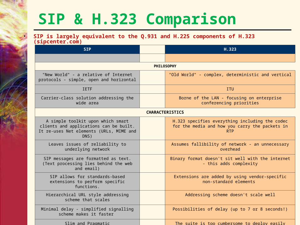
SIP & H.323 Comparison• SIP is largely equivalent to the Q.931 and H.225 components of H.323 (sipcenter.com)
SIP H.323
PHILOSOPHY
"New World" - a relative of Internet protocols - simple, open and horizontal
"Old World" - complex, deterministic and vertical
IETF ITU
Carrier-class solution addressing the wide area Borne of the LAN - focusing on enterprise conferencing priorities
CHARACTERISTICS
A simple toolkit upon which smart clients and applications can be built. It re-uses Net
elements (URLs, MIME and DNS)
H.323 specifies everything including the codec for the media and how you carry the packets in RTP
Leaves issues of reliability to underlying network
Assumes fallibility of network - an unnecessary overhead
SIP messages are formatted as text. (Text processing lies behind the web and email)
Binary format doesn't sit well with the internet - this adds complexity
SIP allows for standards-based extensions to perform specific functions.
Extensions are added by using vendor-specific non-standard elements
Hierarchical URL style addressing scheme that scales
Addressing scheme doesn't scale well
Minimal delay - simplified signalling scheme makes it faster
Possibilities of delay (up to 7 or 8 seconds!)
Slim and Pragmatic The suite is too cumbersome to deploy easily

SIP & H.323 Comparison SIP H.323
SERVICES
Standard IP Centrex services Standard IP Centrex services
Ability to 'fork' calls Not possible in the existing standard
User profiling -
'Unified messaging' -
Presence management -
Unique ability to mix media (e.g. IVR) Cannot mix media within a session
URLs can be embedded in web browsers and email tools
H.323 has no URL format
Works smoothly with media gateway controllers controlling multiple gateways - crucial in a multi-
operator environment
"Shoehorn" interworking with SS7 is problematic - H.323 has trouble connecting calls to and from PSTN endpoints
Seamless interaction with other media - services are only limited by the developers imagination
Services are nailed-down and constricted - voice only ceiling
STATUS
Industry endorsed Popularity due to the fact that it was the first set of agreed-upon standards
Many vendors developing products The majority of existing IP telephony products rely on the H.323 suite
4.3.6. Security
• Integrity• Authenticity• Encryption• Intellectual rights protection
– Digital watermarking techniques embed extra information into multimedia data
– Imperceptible to normal user and irremovable

Security
• At the IP layer security can be provided by IPSec
• Secure RTP (RFC 3711)– Provides 128 bit AES encryption– Confidentiality, authentication and replay
protection– SHA-1 (Secure Hash Algorithm) for
authentication

4.4. QoS• Quality of Service (QoS) methods aim at
trading quality vs. resources to meet the constraints dictated by the user, the functionality and the platform.
• QoS originally developed in network communication, and recently extended to the domain of multimedia communication.
• QoS relevant in multimedia scalable systems, where the resources and the functionality can be controlled by a set of parameters. – Match the performance needs of
applications to available network resources

• Quality of Experience (QoE) is subjective and relates to the actual perceived quality of a service by the user• QoE is the fundamental determinant of performance
for any technology and is the user perception of quality
• This applies to voice, multimedia, and data
• Quality of service (QoS) is an optimization tool designed to deliver a certain Quality of Experience (QoE) by ensuring that network elements apply consistent treatment to traffic flows as they traverse the network– QoS is a mechanism to help achieve QoE.
• QoS mechanisms can only be effective, must implement the critical concepts are:• Separate transmission medium in each
direction• Sending device has complete control over
what is sent• No other device can interfere with the
transmission

• Much has been written about QoS, and can be summarized into three primary jobs:• To minimize end-to-end delay through the
network (VoIP traffic to front of the line)• To minimize the variability in end-to-end delay,
that is, jitter (VoIP traffic to front of the line)• To prevent packet loss (separate queues for the
VoIP traffic)
• QoS doesn’t improve all network traffic performance.

4.4.1. QoS Parameter Metrics
From three primary jobs above will be delivered into :
availability delay (latency) delay variation (jitter) throughput (average and peak rates) packet loss

4.4.2. IETF QoS Efforts
• Policy based IP QoS Solutions– Integrated Services (RSVP protocol):
flow based– Differentiated Services (DiffServ byte
settings): packet based– Multi-Protocol Label Switching
(MPLS): flow+packet based

Defined by RSVP requires resource reservation at each hop end-to-end for each IP packet flow, and end-to-end signaling along nodes in the path
Reserve resources at the routers so as to provide QoS for specific user packet stream
This architecture does not scale well (large amount of states)
a. Int-Serv (Integrated Services): IETF RFC 1633

Integrated Services• IntServ Internet Services model developed by IETF• Requires applications to know their QoS
requirements beforehand and signal intermediate network to reserve resources (bandwidth, buffers)
• Requires use of packet classifiers as well as packet schedulers
• Almost exclusively concerned with controlling the queuing component of end to end delay
• Has three service classes– Guaranteed Service (RTI)– Controlled Load (RTT)– Best-effort

IntServ
• Flow descriptor specifies QoS requirements– Filter spec – specifies information for the
identifying a packet with a given flow– Flow spec – specifies traffic spec in terms of
token bucket parameters (Tspec) and QoS parameters (Rspec) in terms of bandwidth, delay, jitter and packet loss
• Resource Reservation Protocol (RSVP) used to signal network nodes about required resources

RSVP
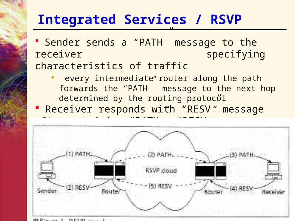
• The sender sends a PATH message to the receiver specifying traffic characteristics
• Every intermediate router along the path forwards the path to the next hop determined by the routing protocol
• The receiver responds with RESV message
Integrated Services / RSVP
Sender sends a “PATH” message to the receiver specifying characteristics of traffic
• every intermediate router along the path forwards the “PATH” message to the next hop determined by the routing protocol
Receiver responds with “RESV” message after receiving “PATH”. “RESV” requests resources for flow

Disadvantages of IntServ
• Routers having to maintain per-flow state for every flow is a large overhead
• Does not scale in the core network• Router state has to be refreshed at regular
intervals increasing traffic overhead• However, RSVP has a place at the edge of
the network
b. Diff Serv IETF RFC 2474 Mark IP packet to specify treatment Per Hop Behaviors (PHBs) based on network-wide
traffic classes Flows are classified at the edge router based on
rules, and are aggregated into traffic classes, allowing scalability
Diff Serv uses the IP header TOS byte (first 6 bits), which is renamed the DS field
Diff Serv defines code points (DSCP) for the DS field, DE (default) = 000000 = best effort, and EF (Expedited Forwarding) = 101110 = low latency, etc.
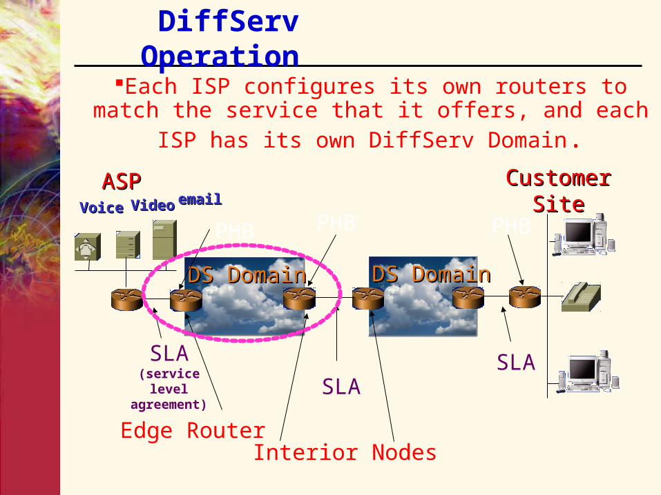
DiffServ Operation
Each ISP configures its own routers to match the service that it offers, and each ISP has its own DiffServ Domain.
DS DomainDS DomainDS DomainDS Domain
VoiceVoice
ASPASPVideoVideo emailemail
Customer SiteCustomer Site
SLA(service level agreement) SLA
SLA
PHB PHBPHB
Edge RouterInterior Nodes
DiffServ
• Removes some of the shortcomings of the IntServ architecture
• Divides network into regions called DS domains. Each domain is controlled by a single entity
• To provide service guarantees the entire path between source and destination must be in some DS domain
• Nodes in a DS domain can be of following types:– Boundary node– Interior node
DiffServ Boundary Node
• Performs admission control to limit the number of flows in a domain
• Performs packet classification by marking each packet with a service class called “Behavior Aggregate”
• Each Behavior Aggregate is assigned an 8-bit code word called a DS code point
• IP ToS field is updated with the code-point

DiffServ Interior Node
• Lies completely within a DS domain. Connects with other interior nodes or boundary nodes within the domain
• Only performs packet forwarding• Packets are forwarded according to some
pre-defined rule associated with the packet class (as indicated by the code point)
• These pre-defined rules are called Per-Hop Behaviors (PHBs)

DiffServ PHB
• Two commonly used PHBs are– Assured Forwarding (AF): Divides incoming
traffic into four classes where each class guarantees a minimum bandwidth and buffer space
• Within each class packets are further assigned one of three drop priorities
– Expedited Forwarding (EF): Departure rate of a traffic class must equal or exceed the configured rate
• Queuing delay is guaranteed to be bounded• Used to provide Premium Service• Requires strict admission control and traffic policing

c. MPLS Fundamentals (IETF RFC 3031) MPLS is a forwarding scheme that tags packets with labels
(independent of layers 2,3) that specify routing and priority Enables scalability by alleviating IP over ATM problems
• Defines a homogeneous network based upon label-switching• Requires all devices (i.e., ATM switches) to be capable of routing
Enables differentiated services via QoS-aware label switched paths (LSPs)
Designed to run over a wide range of media• ATM, frame relay, and Ethernet
MPLS• A router determines the next hop of a packet by doing
a longest prefix match of an IP destination address against entries in a routing table
• This introduces some latency as routing tables can be very large
• Same process repeated for every packet even if these are in the same flow
• IP switching gets around this:– Short label is attached to every packet and is
updated at every hop– This label is used at the next hop as an index into
the routing table to get the next hop (happens in constant time) and next label
– Label is replaced and packet is forwarded to the next hop
– Lends itself to being done in (low-cost) hardware resulting in very high speeds

MPLS• Like DiffServ MPLS network is divided into domains
with boundary nodes called Label Edge Routers (LER) and interior nodes called Label Switching Routers (LSR)
• Packets entering an MPLS domain are assigned a label at the ingress LER and are switched inside a domain by a simple label lookup
• Labels determine QoS• Labels may get stripped off at egress LER and then
get routed conventionally outside the domain• A sequence of LSR to be followed by a packet in an
MPLS domain is called a Label Switched Path (LSP)• To guarantee QoS both source and destination have
to be attached to the same domain or the different domains have to have service level agreements among them

MPLS• A group of packets that are forwarded in the same manner
are said to belong to the same Forward Equivalence Class (FEC)- FECs form the basis of service differentiation
• No limit on number and granularity of FECs• Labels only have local significance
– Two LSRs agree upon using a particular label for a given FEC• Necessary to do label assignments including label allocation
and label to FEC binding on every hop of the LSP before the traffic flow can use the LSP
• Labels can be stacked in FILO order – can be used in tunneling applications
• In a domain only the topmost label is used to make forwarding decisions
• Can be useful in providing mobility– Home agent can push a label on incoming packets and forward
them to a foreign agent– Foreign agent pops of its label and forwards the packet to the
destination mobile host

MPLS Label Assignment• Label assignment can be done in the
following ways:– Topology-driven: LSPs for every possible FEC
are automatically set up between every pair of LSR (zero call setup delay)
– Request driven: LSPs set up based on explicit requests.
• RSVP can be used– Traffic driven: LSPs set up only when LSR
identifies traffic patterns requiring a new LSP• Traffic patterns not requiring an established LSP use
the normal routing method• Combines advantages of above two