cgr-30p premium worksheet - aircraft spruce & specialty co · 2018-09-25 · don’t pick the...
TRANSCRIPT
CGR-30P PREMIUMWorksheet
Replace your Tachometer with the CGR-30P
Download this file, fill it out and then save it. Include it with your order.
www.buy-ei.com
Rev: D

2
General Info:
Aircraft Information: Example
Customer Name Peter Pilot
Customer Phone 555-555-5555
Customer E-mail [email protected]
Aircraft Make | Model Cessna | 182RAircraft Tail Number N5555H
Engine Mfg | Model Continental | O-470U
# of Cylinders | Max HP 6 | 230 HP
[ ] Include a Certificate of Conformance ($10.00)
[ ] Include an 8130-3 ($195.00). Can add up to two weeks to lead time.
All data must be verified for accuracy and must match the POH/AFM and any changes required by any AD’s, Supplements or STC’s. Also, limit and marking information must be cross-checked against the instruments mounted in the aircraft panel. A configuration file for a TSO’d and/or STC’d CGR-30P can only be generated or changed by Electronics International Inc. If any of the information provided on this form is wrong, there may be a reprogramming fee to change the configuration.
Important Information: The information in this document must be verified for accurate and match the air-craft’s hardware and POH/AFM marking requirements. If the data supplied in this document is incomplete or missing, your order will be delayed. Our mission is to get your order shipped as soon as possible.
Pick Your Functions:Every package provides the following functions: RPM – Removing your current RPM gauge provides the location for the CGR-30P. EGT/CHT Bar Graph – All the EGT’s and CHT’s are provided in the kit. Five more Functions of your choice (that may have charges) are included in the kit. Any (N/C) Function of your choice can be added at no charge.
Main Screen: In addition to the above you have 1- Arc Gauge and 3 - Strip Gauges on the Main Screen. All of these locations can be configured for primary replacement gauges. Primary gauges are those listed in the POH/AFM and have red and/or yellow limits associated with them.

3
Secondary Screen: On the Secondary Screen you have 6 - locations that can be configured as Strip Gauges, Digital Gauges or Annunciators. Based on your selections, EI will determine the gauge type. One of these gauges can be a primary gauge with red and/or yellow limits (it will be annunciated on the Main Screen).
Pick your functions and place them on the Main and Secondary Screens. You can pick up to 10 functions. Five of these functions come with the unit and are free. Anything over five may have a charge (some functions re-quire probes, sensors or modules, others do not).
Rules:
1. Only one Primary Gauge can be placed on the Secondary Screen.
2. All Fuel Level Gauges must be placed on the Main Screen.
3. If your aircraft has M.P, it will be the second Arc Gauge on the Main Screen.
4. Gauge locations are subject to approval and will most likely be changed by E.I. to meet standardiza-tion requirements.
Main Screen Selections: With RPM, EGT’s and CHT’s select 5 more primary functions to be displayed on the Main Screen(these are included in the price):
Sel * Function Primary Gauge?M.P. (2nd Arc on Main Screen) YesFuel Flow In some injected engines.
See POH/AFMFuel Pressure (not available for aircraft without a fuel pump)
Yes
Left or Main Fuel Level (must be placed on Main Screen)
Yes, consider using CGR-30C
Right Fuel Level (must be placed on Main Screen) Yes, consider using CGR-30CAux Fuel Level (can be on secondary screen if fuel is transferred to another tank)
Yes, consider using CGR-30C
Oil Pressure YesOil Temp YesTIT YesVolts See POH/AFMAMPS See POH/AFMVac YesCarb Temp See POH/AFMEst Fuel Remaining No
* Selected the one Primary function to be displayed on the Secondary Screen.
Loc

4
Secondary Screen Selections: You have 5 more Secondary Screen locations for which you can pick functions. These cannot be primary gauges. Don’t pick the same functions selected above. Some functions are free, oth-ers have charges.
Sel Function Primary Gauge? PriceVolts See POH/AFM. If primary, cannot be selected here. N/CAMPS See POH/AFM. If primary, cannot be selected here. $39OAT in ‘F No $98OAT in ‘C No $98Est Fuel Remaining No N/CHorsepower (requires M.P.) No N/CFlight Timer No N/CEngine Timer No N/CTach Timer No N/CLocal Time No N/CZulu Time No N/CFuel Flow See POH/AFM. If primary, cannot be selected here. $295Carb Temp See POH/AFM. If primary, cannot be selected here. $98 Hydraulic Pressure No $250G-Meter (does not have peak hold)
No $295
Cabin Pressure See POH/AFM. If primary, cannot be selected here. $150Cabin Differential Pressure See POH/AFM. If primary, cannot be selected here. $150IAT See POH/AFM. If primary, cannot be selected here. $98CDT No $98CO Detector (no discounts) No $475Other, provide data
Place the Functions selected on the Main and Secondary screens (locations may be changed by E.I.):
Locations for MP and RPM should follow the controls from Left to Right.
Loc

5
Marking Information Required:Provide marking and other information for only the functions selected.
Tachometer:
Markings:
(Low) Range (High) Color Example2000 | 2500 | Green2700 | 9990 | Red
[ ] My engine is equipped with an Electronic Ignition. If this is the case, we need the pulses per revolution and voltage levels of the RPM signal for each set of spark plugs:
_____________________________________________________________________________. Example: Left: 2 pulses/rev, 0-5 pulse, Right: standard mag.
Manifold Pressure:This function uses the PT-30ABS Pressure Transducer.
Markings: If markings are not specified in the POH/AFM, write “00 | 00.” Pressure requirements over 32”Hg require a different transducer and has an up charge.
(Low) Range (High) Color Example15.0 | 25.0 | Green
[ ] Use the MP transducer that comes standard PT-30ABS (0 to 32” Hg). No Charge.
[ ] Replace the MP transducer with the PT-60ABS (0 to 70” Hg). Up charge of $ 49.95.
[ ] Replace the MP transducer with the PT-200ABS (0 to 210” Hg). Up charge of $ 74.95.
If the MP tube is a hard line, you may need a flare fitting to interface to the Vacuum Pressure Transducer.
[ ] Add a 1/4,” 37 degree Flare Fitting to the kit ($19.95 ea.).
Units:
Loc
Range
1 or .5
6
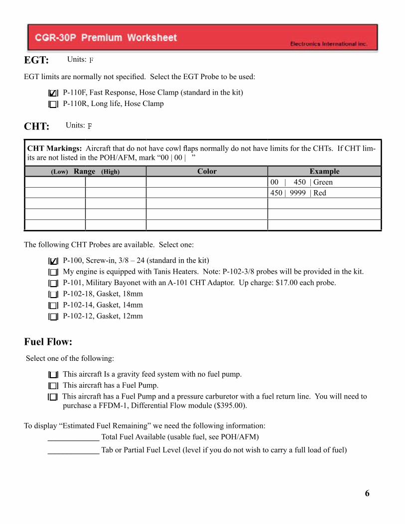
EGT:EGT limits are normally not specified. Select the EGT Probe to be used:
[ ] P-110F, Fast Response, Hose Clamp (standard in the kit) [ ] P-110R, Long life, Hose Clamp CHT:
CHT Markings: Aircraft that do not have cowl flaps normally do not have limits for the CHTs. If CHT lim-its are not listed in the POH/AFM, mark “00 | 00 | ”
(Low) Range (High) Color Example00 | 450 | Green450 | 9999 | Red
The following CHT Probes are available. Select one:
[ ] P-100, Screw-in, 3/8 – 24 (standard in the kit) [ ] My engine is equipped with Tanis Heaters. Note: P-102-3/8 probes will be provided in the kit. [ ] P-101, Military Bayonet with an A-101 CHT Adaptor. Up charge: $17.00 each probe. [ ] P-102-18, Gasket, 18mm [ ] P-102-14, Gasket, 14mm [ ] P-102-12, Gasket, 12mm
Fuel Flow: Select one of the following:
[ ] This aircraft Is a gravity feed system with no fuel pump. [ ] This aircraft has a Fuel Pump.
[ ] This aircraft has a Fuel Pump and a pressure carburetor with a fuel return line. You will need to purchase a FFDM-1, Differential Flow module ($395.00).
To display “Estimated Fuel Remaining” we need the following information: _____________ Total Fuel Available (usable fuel, see POH/AFM)
_____________ Tab or Partial Fuel Level (level if you do not wish to carry a full load of fuel)
Units:
Units:

7
Notes:
a) Also available is a FFAM-1, Fuel Flow Add Module. This module adds the fuel flow for two Flow Transducers ($395.00).
b) Primary Fuel Flow (this is normally derived from metered fuel pressure at the flow divider):
1) If any limit on your current primary fuel flow gauge is marked in pressure only, the CGR-30P must also display metered fuel pressure to replace this gauge.
2) If all the limits on your current primary fuel flow gauge are marked in flow (even though pres-sure may also be shown), the CGR-30P Fuel Flow system will replace this gauge and Metered Pressure does not need to be measured
Fuel Flow Markings: Example shows no limits.
(Low) Range (High) Color Example 00 | 00 |
Fuel Pressure: Select one of the following:
[ ] Fuel Pressure is monitored at the fuel pump.[ ] This is a turbocharged aircraft and fuel pressure is referenced to the Upper Deck. You must pur-
chase the PT-30GA Pressure Transducer ($195.00) to measure the Upper Deck. [ ] Fuel Pressure is monitored at the flow divider. [ ] This is a gravity feed system with no fuel pump. Note: Fuel Pressure cannot be monitored. [ ] Fuel Pressure is not monitored.
Markings:
(Low) Range (High) Color Example 0.0 | 9.0 | Red 9.0 | 14.0 | Green14.0 | 999.0 | Red
Units:
Units:
Loc
PT-100

8
Fuel Level:The CGR-30P can provide accurate fuel level readings for straight and level flight. By calibrating the CGR-30P to the fuel tank, nonlinearity in the tank’s shape and nonlinearity in the Fuel Level Sensor can be compensated. The CGR-30P cannot correct for inconsistent or non-repeatable readings from a Resistive Fuel Level Sensor. Unfortunately, many Resistive Fuel Level Sensors (and in some cases even new units) exhibit these problems. If you find inconsistent or inaccurate fuel level readings (due to a defective Resistive Fuel Level Sensor), you must have the sensor replaced or repaired. Read the “Important Notice” in the CGR-30P Operating Instructions. Fuel Level Sensors are not provided in the kit. The following are some E.I. probes and modules available:
P-300C: This is ¾” OD capacitive probe ($349.00).
P-300C Mini: This is a 3/16” OD capacitive probe ($298.00).
P-300M: Magnetic Float Sensor, replacement for Resistive Sensor ($395.00).
RFLM-4: Provides the current for up to 4 resistive fuel level sensors ($98.00).
FLAM -4: Monitors up to 4 capacitive fuel level probes in one tank and outputs the signal to the EDC-33P as single tank ($475.00).
Important Notice: Only use the RFLM-4 for a Resistive Probe, otherwise damage will occur.
For each Fuel Level Probe we require the following information:
DisplayedName Probe Type Tank Configuration
6 Characters
Select only one:
[ ] Resistive Probe (an RFLM-4 will be provided)
[ ] E.I. P-300M magnetic probe.
[ ] E.I. P-300C capacitive probe.
[ ] Penny Cap Capacitive Probe (select only one below):
[ ] The Signal Conditioner box provides the signal.
[ ] The signal will come from the probes.
Full Fuel Level: _________________.
Select only one:
[ ] This tank can be selected to feed the engine.
[ ] Fuel is only transferred from this tank to another.
Note: All displayed Fuel Levels must be in the same units-of-measure.
Units:
Snap

9
DisplayedName
Probe Type Tank Configuration
6 Characters
Select only one:
[ ] Resistive Probe (requires a RFLM-4)
[ ] E.I. P-300M magnetic probe.
[ ] E.I. P-300C capacitive probe.
[ ] Penny Cap Capacitive Probe (select only one below):
[ ] The Signal Conditioner box provides the signal.
[ ] The signal will come from the probes.
Full Fuel Level: _________________.
Select only one:
[ ] This tank can be selected to feed the engine.
[ ] Fuel is only transferred from this tank to another.
DisplayedName
Probe Type Tank Configuration
6 Characters
Select only one:[ ] Resistive Probe (requires a RFLM-4)[ ] E.I. P-300M magnetic probe.[ ] E.I. P-300C capacitive probe.[ ] Penny Cap Capacitive Probe (select only one below):
[ ] The Signal Conditioner box provides the signal.
[ ] The signal will come from the probes.
Full Fuel Level: _________________.
Select only one:
[ ] This tank can be selected to feed the engine.
[ ] Fuel is only transferred from this tank to another.
If some other fuel level probe is to be used, provide specification for the probe:
_____________________________________________________________________
Snap
Snap

10
Oil Pressure:This function uses the PT-100GA Pressure Transducer.
Markings:
(Low) Range (High) Color Example 0 | 25 | Red 25 | 90 | Green100 | 9999 | Red
Oil Temperature:This function uses the P-120 Oil Temp Probe.
Markings:
(Low) Range (High) Color Example 0 | 65 | Yellow 65 | 200 | Green200 | 240 | Yellow240 | 9999 | Red
TIT:
Markings:
(Low) Range (High) Color Example 0 | 1650 | Green1650 | 9999 | Red
Select the probe type:
[ ] P-111, 1/8” NPT (w/ 6’ cable, $98.00). [ ] P112, 7/16-20 (w/ 6’ cable, $98.00). [ ] P114, 1/4” NPT (w/ 6’ cable, $98.00). [ ] P-110, Hose Clamp (w/ 6’ cable, $98.00).
Units:
Xducer
Units:
EDC
EDCUnits:

11
Volts:The voltage limits are set by E.I. Select one of the following:
[ ] 12-Volt System. [ ] 24-Volt System.
Amps:Normally Amps do not have limits specified. A 100 Amp shunt is provided in the kit or the CGR-30P can be connected to the aircraft’s existing shunt. To do this the value of the existing shunt must be provided. See www.buy-ei.com and look under VA-1A Downloads for help on determining the value of your existing shunt. Select one of the following:
[ ] Use the 100 Amp Shunt that comes with the system.
[ ] The aircraft’s Existing Shunt will be used, Value is ____________ Amps at ______________ mV.
Note: The EDC-33P only has only one channel to monitor current. The FM-VA-3 module (when con-nected to temp channels on the EDC-33P) allows three more current measurements.
[ ] Add the FM-VA-3 to the Kit ($195.00).
[ ] Add the following number of S-50 Shunts to the kit: _______________ ($39.00 ea.).
Vacuum Pressure:If markings are not listed in the POH/AFM, we suggest using Green 4.5 to 5.5. This function uses the PT-05Diff Pressure Transducer. If the vacuum tube is a hard line, you may need a flare fitting.
[ ] Add a 1/4,” 37 degree Flare Fitting to interface to the Vacuum Pressure Transducer ($19.95 ea.)
Markings:
(Low) Range (High) Color Example4.5 | 5.5 | Green
Units:
12
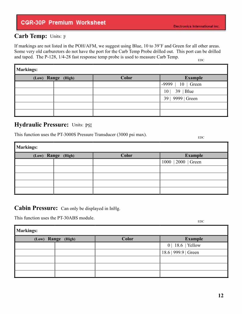
Carb Temp:If markings are not listed in the POH/AFM, we suggest using Blue, 10 to 39’F and Green for all other areas. Some very old carburetors do not have the port for the Carb Temp Probe drilled out. This port can be drilled and taped. The P-128, 1/4-28 fast response temp probe is used to measure Carb Temp.
Markings:
(Low) Range (High) Color Example-9999 | 10 | Green 10 | 39 | Blue 39 | 9999 | Green
Hydraulic Pressure:This function uses the PT-3000S Pressure Transducer (3000 psi max).
Markings:
(Low) Range (High) Color Example1000 | 2000 | Green
Cabin Pressure: Can only be displayed in InHg.
This function uses the PT-30ABS module.
Markings:
(Low) Range (High) Color Example 0 | 18.6 | Yellow18.6 | 999.9 | Green
Units:
Units:
EDC
EDC
EDC

13
Cabin Differential Pressure:This function uses the PT-05Diff module.
Markings:
(Low) Range (High) Color Example 0 | 4.0 | Green 4.0 | 9999 | Yellow
Induction Air Temperature (IAT):This function uses the P-128 Temperature Probe.
Markings: Example shows no limits.
(Low) Range (High) Color Example00 | 00 |
Compressor Discharge Temperature (CDT):This function uses the P-128 Temperature Probe.
Markings: Example shows no limits.
(Low) Range (High) Color Example00 | 00 |
Units:
Units:
EDC
EDC
Units:
EDC

14
Carbon Monoxide: Measured in ppm.
This Function requires an RS232 Port on the CGR. The CO Guardian Option is $495.00. With this option only one EDC can be connected to the CGR. When place on the secondary screen the red and yellow limits will not be annunciated. If markings are not specified in the POH/AFM, we recommended the following limits.
Markings:
(Low) Range (High) Color Example 0 | 25 | Green 25 | 75 | Yellow 75 | 9999 | Red
G-Meter:The G-Meter function provides a real time g-force display on the CGR-30P. The CGR-30P does not provide a peak-hold function, but the g-force readings are recorded for the entire flight. To capture the g-forces for all phases of the flight with no gaps, set the “Data Sample Rate” to 0.3 seconds. The G-Meter option can be used to capture g-forces in slow flight, hard landings, turbulence, hard pull-ups, steep turns, aerobatic maneuvers, stalls or spins. When placed on the secondary screen, the red and yellow limits will not be annunciated.
Markings:
(Low) Range (High) Color Example-9999 | -1.5 | Red - 1.5 | 3.8 | Green 3.8 | 9999 | Red
EDC

15
FAILURE TO SIGN THIS DOCUMENT WILL RESULT IN AN INCOMPLETE FORM AND WILL DELAY YOUR ORDER.
* Be sure you have ordered the hardware to support all the functions listed in this document.
* Check that all range and configuration information is complete and accurate.
I (the undersigned) have entered and verified all the limits, markings and aircraft configurations listed in this worksheet to be correct and taken from the information in the aircraft’s POH/ AFM which includes any changes mandated by any AD’s, Supplements and STC’s. When necessary, I have checked with my FAA certified me-chanic to insure all of the data listed above is correct.
I understand there is important safety information in the Installation and Operating Instructions that must be read before installing the CGR-30P and flying the aircraft.
Comments:
-------------------------------------- ---------------------------------------- ------------------------
Owner/Ptilot’s Printed Name Owner/Pilot’s Signature Date
To setup a new signature preform the following: 1. Select the Signature box above. 2. Select “Configure Digital ID.” 3. Select “Create a New Digital ID.” 4. Select “Save to File.” 5. Fill-out the form. Don’t forget you password (pin name), you will need it to sign this form. 6. Rename and save the worksheet.