cgj bored piles
DESCRIPTION
bored pileTRANSCRIPT

200
Design of bored piles in residual soils based on field-performance data
M. F. CHANG AND B. B. BROMS
School of Civil and Structural Engineering, Nanyang Technological Institute, Nanyang A venue, Singapore 2263
Received April 9, 1990
II Accepted October 18. 1990
The current practice for the design of large-diameter bored piles in residual soils in Singapore is based on the calculatedstatic capacity of the piles. Insufficient consideration of the load-transfer mechanism and overreliance on'pile loadtests have led to conservative designs. A better alternative is to adopt a load-displacemenl analysis method lhal providesinformation on the load distribution along the pile and the complete load-displacement relationship. Results of full-scale load tests on instrumented piles indicate that bored piles in residual soils in Singapore behave in the same wayas in stiff clay and weak rocks elsewhere in that the load transfer at the working load is domina led by shafl friction.Simple correlations exist between the standard penetration resisltance and the load-transfer parameters. An exampleillustrates that the proposed design procedure that uses these simple correlations and the load-transfer method is animprovement over present design methods.
Key words: bored piles, cast-in-placc piles, design, drilled piers, field test, load transfer, residual soil, shaft resistance.
La pratique courante pour la conception de pieux rores a grand diametre dans les sols residuels a Singapour est baseesur la capacite statique calculee des pieux. Une prise en compte insurfisante du mecanisme de transfer! de charge etune con fiance indue dans les essais de chargement ont conduit a des conceptions trop sec~ritaires. Une meilleure alter-native consiste a utiliser une methode d'analyse charge-deplacement qui rournit de I'inrorm:\tion sur Ia distributionde la charge Ie long du pieu et sur la relation complete charge-deronnation. Dcs resultats d'eSsais de chargement apleine echelle sur des pieux instrumentes indiquent que les pieux fores dans des sols residuels de Singapour se compor-tent de la meme ra~n que dans les argiles raides ct les roches molles trouvees ailleurs, en ce que, a la charge utile,Ie transfert de charge est domine par Ie frottcment Ie tong du fut. Des correlations simples existent entre la resistanceA la penetration standard et les parametres de transfert de charge. Un exemple montre que la procedure de conceptionproposee, qui utilise ces correlations simples avec la methode de transrert de charge, presente une amelioration surles methodes courantes de conception.
Mots des : pieux fores, pieux coules en place, conception, essai de chantier, transfert de charge, sol residuel, resistancede fut.
(Traduit par la redaction)
Can. Gcotcch. J. 18, 200-209 (1991)
Introduction
Approximately 200 000 -400 000 m of large-diameterbored piles are installed in Singapore each year. The pilesare typically 0.6-1.2 m in diameter, 15-20 m in length, andare designed to carry approximately 1.8-7.0 MN of axialload. Most of these piles are constructed in residual soilsderived from the Bukit Timah Granite and weatheredsedimentary rocks of the Jurong Formation in Singapore.Bored piles are extensively used in Singapore because of thehigh capacity, relatively low costs, easy kngth adjustment,and low noise and vibration levels during construction.
Present design methods for bored piles in Singapore areprimarily based on the calculated static capacity and a globalfactor of safety. The shaft resistance is very oftenunderestimated and sometimes totally ignored. As a result,the designs are often conservative. These traditional designmethods rely on verification by pile load tests that are costlyand time consuming. A large number of piles are tested eachyear, but they are often neither instrumented nor loaded tofailure. As a consequence, these tests have not significantlyhelped to improv~ the design of the bored piles in Singapore.
Since the early 1980s, a number of studies have been carriedout in Singapore on fully instrumented bored piles in theOld Alluvium and in residual soil and weathered rock for-mations. These studies show that load transfer in theserelatively stiff materials is primarily through shaft resistanceand that, at the working load, the mobilized point or baseresistance is usually small. These findings are similar to thosePnnl.d in Conada I Impo;... au Canada
for drilled piers in weak rock (Horvath and Kenney 1979).One should consider this observed load-transfer mechanismin the design of bored piles in these and similar geologicalmaterials.
Careful considerations of the geology and the engineeringcharacteristics of residual soils and the limitations of thetraditional design methods for bored piles in these soils pro-vide a basis for improving current design methods. Loacl-transfer data from studies of fully instrumented piles canbe compared with site-specific soil properties to develop fieldperformance based correlations. In particular, load-transf<:rparameters or curves estimated from site investigation resul,~scan be used in load-displacement analyses, such as the load-transfer method developed by Coyle and Reese (1966), topredict the load-cdisplacement relationship. Such a relation-ship will provide a sound basis for a rational design of boredpiles in residual soils in Singapore and possibly also in oth<:rsimilar geological formations.
Residual soils in SingaporeResidual soil includes classical "residual soil." completely
weathered rock, and highly weathered rock, which are "soil-like" materials of weathering grades VI, V, and IV, respe4;-lively, according to Little (1969) and the Geological SocielYEngineering Group (1990). The residual soils in Singaporeare mainly derived from the Bukit Timah Granite or thesedimentary rocks of the Jurong Formation (Public Works

CHANG AND DROMS 201
predominantly that of a clay, even though the soil is com-posed primarily of sand- and silt-sized particles. The soilwill probably behave like an undrained material under nor-mal static loads, although it should be noted that the soilis usu~lIy partially saturated above the groundwater table.The undrained shear strength is typically between 50 arid200 kPa or higher; its large variation is mainly due to thespatially heterogeneous nature and the varying degree ofsaturation of the soil. The initial void ratio varies from 0.6to 1.1, based on the moisture contents reported by Y onget a/. (1985). The value of Cc is between 0.1 and 0.6,similar to that of the granitic residual soil. This variationof Cc corresponds to a m of between 8 and 37 (Janbu1967).
The residual soils of Singapore, in general, have a lowcompressibility, and they gradually become stiffer withdepth. This is particularly true for the granitic residual s<J,il.Because of the high clay content or the "clay effect" causedby clay coating of the silt- and sand-sized particles, theresidual soils often behave like "overconsolidated" clay withrespect to both the strength and the compressibility. Theyare often treated as stiff sedimentary clays.
Since these residual soils, particularly that of the JurongFormation, are highly variable and relatively hard topenetrate, "undisturbed" sampling is very difficult. Theshear strength and deformation properties as determined bylaboratory tests are often not representative because of thesample disturbance. Pressuremeter tests can be carried ()utwithout much difficulty, but the results are of limited valluemainly because of the large scatter associated with the highvariability of the material. As a result, the standard penetra-tion test (SPT), occasionally supplemented by the Swedishram sounding test, is commonly used in Singapore toestimate the undrained shear strength of residual soils(Chang 1988). A correlation between the standard penetra-tion resistance (N, blows/O.3 m) and the undrained sh,~arstrength (cu = 5-6N (kPa», as proposed by Stroud (19')'4),is used for materials with N ~ 60. When N > 60, the ra,tioof cui N becomes higher than 5-6 (MPa), and the corr(:la-tion, expressed in a scale of Cu and N values, proposed byCole and Stroud (1977) is often used.
Local practice for design of bored piles
Bored piles constructed in Singapore are commonlystraight sided. The boreholes are normally excavated usingrotary drilling rigs and short-night augers. The piles are r10r-mally concreted "dry" in one continuous pour. The tremiemethod is employed when water is present in the boreholes.The time between the drilling and concreting is normally I~eptshort to reduce the softening of the borehole wall.
The design of bored piles in Singapore is based on thetraditional design methods. The static ultimate capacity isusually estimated from
[I) Qu = Qp + Qs = qp Ap + Is As
where qp is the point or base resistance, J. is the unit shaftresistance, and Ap and As are the cross-sectional area andthe surface area of the pile, respectively. A single global fac-tor of safety (F) of 2.5-3.0 is commonly used to evaluatethe allowable load according to Q. = Qu/F.
The point resistance is commonly estimated from theundrained shear strength (cu) of the residual soils. Ollie of
Department of Singapore, 1976). Each of these two forma-tions covers about one-third of Singapore Island.
The Bukit Timah Granite, generally light grey andmedium grained, consists predominantly of feldspar(60-650/0) and quartz (300/0), with small amounts of biotiteand hornblende. The granite is covered by a thick over-burden of typically 10-35 m of residual soil that has beenfonned primarily through chemical weathering and altera-tion of the parent rock minerals as a result of the hot andhumid environment in Singapore (Poh et oJ. 1985).
The granitic residual soil ranges from silty sand to clayeysilt to sandy or silty clay. The material is usually cohesive,and the plasticity is medium to high, depending on the claycontent and the degree of weathering. The consistency is gen-erally medium stiff to very stiff. Core stones occuroccasionally.
The Jurong Formation, a sedimentary rock formation ofLate Triassic and Lower to Middle Jurassic age, consistsmainly of grey to black interbedded mudstone and sand-stone, or reddish sandstone and mudstone conglomerate,depending on its occurrence. Six different facies (types) havebeen recognized.
The rocks, particularly the mudrock, vary considerablyeven within a single site, and the bedding contacts are oftenweak and ruptured (Pitts 1984). The effect of weatheringhas reduced most of the facies of the Jurong Formation toa similar end product (Public Works Department ofSingapore 1976). The weathered rock is often weak andfriable, although the structure of the rock tends to be wellpreserved to a great depth (Pitts 1984).
The residual soil derived from the Jurong Fonnation con-sists mainly of interbedded layers of clayey silt and sandyclay of medium plasticity and clayey to silty sand. The soilis heterogeneous and highly variable because of thevariability of the parent rock, the high fracture frequency,and the thin beddings. The weathered material is mostlycohesive and the consistency is generally stiff to hard. Thethickness of the different layers varies from a few centimetresto tenths of metres.
The engineering properties of the residual soil of graniticorigin have not been studied extensively. Poh et of. (1985)have reported that the granitic residual soil is mainly sandyand clayey silt to sandy and silty clay, and its plasticity indexranges from 10 to 50, similar to that of kaolinite. The per-meability ranges from 10-5 to 10-9 m/s. The shearingcharacteristic of the soil is usually governed by the undrainedshear strength because of the low permeability, even thoughthe soil is often partially saturated above the groundwatertable. The undrained shear strength of the soil normallyincreases with depth and ranges from 30 to 200 kPa. Theinitial void ratio of the soil is generally between 0.8 and 1.1,and the compression index (Cc) is between 0.05 and 0.4.This variation of Cc corresponds to a modulus number (m)of between 12 and 83 (Janbu 1967).
The engineering properties of the residual soil of theJurong Formation have not received much attention.A study by Yong et oJ. (1985) indicates that the permeabilityof the soil, based on consolidation tests, is of the order of10-6 mts. On the other hand, Morton and Sayer (1985)have reported that the permeability of the same soil istypically 10 -9 m/s.
According to Yong et oJ. (1985), the engineeringbehaviour of the residual soil of the Jurong Formation is
CAN. GEOTECH. J. YOLo 28, 1991202
group. On the other hand, Holt et oJ. (1982) found, fromload tests of bored piles, that in completely decomposedgranite of Hong Kong the ratio of Esl N increased withincreasing penetration resistance. The back-calculated ratioranged from 0.4 to 0.8 (MPa) for 50 < N < 150 and! wasapproximately 1.0 (MPa) for N > 150. Chang and Goh(1988) used an EsIN ratio of 0.8 (MPa), which correspondsto Es/cu = 130 (Butler 1974), to analyze some bored pilesin residual soils in Singapore and found that the settlementat the working load was overpredicted by as much as 1000/0in some cases. As an approximation, it is reasonable toassume that Es = 1.0N (MPa) for the design of bored pilesin residual soils with N :s 200 in Singapore. Then, Op ~:mm)can be expressed as
[5] 0 = ill Qp NL
where Q (in kN) is the applied load and L (m) i:i theembedded pile length.
The design of bored piles in Singapore commonly ill1cor-..porates load tests that could be either proof test~; forevaluating the settlement at the working load or ultimateload tests to assess the static capacity and to check the !,truc-tural integrity of the pile. Most of these tests have been per-formed in the residual soil of the sedimentary Jurong For-mation. Typically, about 10/0 of the installed piles are prooftested. The maximum applied load ranges from 1.5 to2.0 times the design load. Preliminary load tests are usuallyrequired for major projects prior to the installation (If theproduction piles to verify the design assumptions. In suchcases, the piles are either loaded to 2.5-3.0 times desigl1loador occasionally tested to failure.
Specifications in Singapore generally require that the max-imum total settlement of a large-diameter pile shoub! notexceed 25 mm at 2.0 times working load, regardless (,f thelength of the pile (Public Works Department and Hollsingand Development Board, Singapore). The Mass Rapid Tran-sit Corporation of Singapore specifies that the maximumsettlement should not exceed 6-9 mm at the working loadand 9-20 mm at 1.5 times the working load (Buttlinl~ andRobinson 1987). These settlements limits or acceptancecriteria for test piles are mainly governed by the maximumdifferential settlements that can be tolerated by the sup-ported structures.
the most common relationships is qp = Cu Nc' whereNc = 9 if D < 1.0 m and Nc = 5 if D 2:: 1.0 m, where Dis the diameter of the pile. An "equivalent" undrainedstrength is used when the soil is partially saturated. TheseNc values are similar to those adopted in Canada for verystiff clays and tills (Canadian Geotechnical Society 1985).
The unit shaft resistance of bored piles, if not ignored,is nonnally estimated in Singapore by the a-method:Is = a CU' The adhesion factor a varies with the undrainedshear strength and the construction method. An a-value of0.45, as suggested by Skempton (1959) for stiff, fissuredLondon clay, is commonly assumed in Singapore. Alter-natively, the shaft resistance is estimated directly from theN values, A well-known relationship Is = 2N (kPa), pro-posed by Meyerhof (1976) for driven piles in sand, is some-times used for the design of bored piles in residual soils inSingapore (Broms et 01. 1988). The maximum Is value isoften limited to 120 kPa. Theis values estimated from thisrelationship are similar to those reported by Buttling andRobinson (1987) for a range of weathered materials inSingapore.
Using Cu = 5-6N (kPa) based on Stroud (1974) andIs = 2N (kPa), one can calculate the static capacity forpiles in weathered materials with N ~ 60 directly from theN values as follows
[2]and[3] Qu = 2 NsAs + 30 Nb Ap for D ~ 1.0 m
In [2] and [3], Ns is the average standard penetration resis-tance along the pile shaft, Nb is the average $tandardpenetration resistance between 4D above and D below thepile base, and As and Ap (m1 are the surface area of thepile shaft and the cross-sectional area of the pile base,respectively; ,
Reliable prediction of the settlement for single piles nor-mally requires pile load tests. The interpretation is some-times based on the theory of elasticity (e.g., Poulos andDavis 1968). The settlement of an incompressible single pile,6p' that is relevant to cases where the pile material is muchstiffer than the surrounding soil, in a finite compressiblelayer is
[4] ~p = ~ I~E5L
where Q is the applied load, E5 is an equivalent modulusof elasticity of the soil, L is the pile length, and I~ i$ aninfluence factor that depends on the LID ratio of the pileand the location of the underlying incompressible layer.
For most bored piles installed in residual soils in Singapore,the LID ratio is typically between 15 and 25. Assuming aPoisson's ratio of between 0.2 and 0.4, the average valueof [~ is approximately 1.25 when the thickness of theunderlying compressible layer below the pile base is notgreater than one-half of the pile length. A study of decom-posed granite in Hong Kong by Whiteside (1986), on thebasis of horizontal-plate loading tests, suggests that themodulus of elasticity of completely decomposed granite canbe estimated from E5 = I.W (MPa). This relationship isthe same as that reported by Cole and Stroud (1977) for aweak rock with an average N value of 200 in the UnitedKingdom based on the settlement observation of a pile
Qu = 2 NsA~ + 45 Nb Ap for D < 1.0 m
Limitations of traditional design methodsThe axial displacement that is required to fully mobilize
the shaft resistance for bored piles is small, typically 5-4> mm(Whitaker and Cooke 1966; Aurora and Reese 1977; Hclrvathand Kenney 1979) or 5-10 mm (O'Neill and Reese 1972).In contrast, a relatively large displacement, approximately5 (Aurora and Reese 1977) or 10'10 (Woodwardel at. 1972)of the pile diameter, is required to mobilize the maximumpoint resistance. Thus, at the working load, the shafl~ fric-tion plays a predominant role. This difference in the re<;luireddisplacement for full mobilization of resistance and its effecton pile behaviour are not considered in traditional dlesignmethods for bored piles in residual soils in Singapore.
The high safety factor (2.5-3.0) used in traditional designmethods provides some protection against excessive !iettle-ments. The settlement of a bored pile with a diameter les; than0.6 m and a safety factor of at least 2.5 will normally not
CHANG AND BROMS 203
exceed 10 mm at the working load (fomlinson 1977). How-ever, for piles larger than 0.6 m in diameter, the settlementincreases with increasing pile diameter. It is common thata factor of safety that is adequate to ensure that the soilor the pile does not fail is insufficient to limit the settlementat the working load (Whitaker 1976). Usually, the settlementof the pile has to be estimated from full-scale proof tests.
One possible improvement of the traditional designmethods is to use different partial factors of safety for theshaft resistance and the point resistance:
[6] Q. = ~ + ~Fs Fp
where Fs and Fp are partial factors of safety. Variousvalues of Fs and Fp have been suggested (Skempton 1966;Burland e/ 01. 1966) to take into account the uncertaintiesinvolved in the assessments of Qs and Qp and the differentdisplacements required for full mobilization of the two resis-tance components. However. because of the large displace-ment required to mobilize the point resistance and the dif-ficulties to clean the bottom of the borehole before thecasting, it is advisable to consider only the shaft resistancein the design. The allowable load is then
[7] Q. = ~Fs
where Fs is a factor of safety which can be taken as 2.0.A lower value of 1.5 can be used if the skin friction resistanceis determined by full-scale load tests. The neglect of end-bearing resistance can be considered as an addition to thesafety factor.
The current practice of verifying the design of bored pilein residual soils in Singapore by load tests adds substantiallyto the cost of a project, since load tests are expensive.Routine proof tests or even ultimate load tests do not alwaysprovide sufficient information about the load-transfer mech-anism that is needed to improve present design methods.The use of partial safety factors relies heavily on local expe-rience, and it does not provide any information on pile settle-ments. This approach is suitable only for the preliminarydesign of bored piles. In the final design, one should con-sider the complete load-displacement curve obtained fromload tests on instrumented bored piles or from a load-displacement analysis using field-performance data.
(case 5). The diameter (D) of the pile ranged from 0.4tj to1.0 m, and the length (L) varied between 6.0 and 28.5 m.In addition, two case studies involving bored piles with amaximum diameter of 1.50 m and a maximum length of12.4.m in fractured rock or "rock-like" weathered m~lte-rial were reported by Radhakrishnan et al. (1985) ,lndRadhakrishnan and Leung (1989). The piles were constructedgenerally dry in boreholes excavated by rotary drilling usingshort-flight augers. Most piles were tested in compressionup to 1.5-2.5 times the design load using the maintained-load method. However, the majority of piles investigatedby Chang and Goh (1988) were provided with a base plateand subjected to pull-out tests. Several of the compressionpiles were preliminary t~t piles, but only a few were loa~iedto failure.
Most of the piles were instrumented with vibrating-Ylirestrain gauges and telltales, although rebar stressmeters ~mdload cells were used in some piles. The vibrating-wire straingauges were attached either directly on to the main reinforce-ment or to separate steel bars that were protected by cementmortar. These gauges were found to be very reliable. Tellt:ileswere found to be difficult to install when the piles were longand more than one section of steel cage was required.Telltales were also found to be inadequate when the pileswere short.
In the analyses of test results, load-transfer curves repre-senting the relationship between the mobilized resistance ~rndthe corresponding pile displacement for various supportinglayers were deduced from the reported load-settlement dataand the measured strain distribution. Two key paramet'~rs,the fully mobilized resistance and the corresponding criticaldisplacement (Vijayvergiya 1977), were estimated from thededuced load-transfer curves whenever possible. Typicalload-transfer curves for bored piles in residual soils inSingapore have been reported by Buttling and Lam (19'88)and Chang and Goh (1988).
Table I summarizes the results from the piles that "'eretested in compression. The results of pull-out tests, repoltedby Chang and Goh (1988), are summarized in Table 2. InTable I, the fully mobilized point resistance (qp) could notbe determined because the degree of mobilization of p<)intresistance was too low, even at the maximum applied load.The mobilized tip load, at the working load, was generallysmall and less than 10-20'10 of the applied load. This find-ing is similar to that experienced in Malaysia. Toh el al.(1989) reported that. for bored piles in a weathered sedimlen-tary rock formation in Malaysia, the mobilized tip load wasapproximately 10'10 of the applied load before the sllaftresistance had been fully mobilized over a significant pilelength. These results highlight the importance of shaft fric-tion on the behaviour of bored piles in residual soils. Tohet al. (1989) found that qp = 27-60N (kPa) from two pilesthat were tested to failure.
The unit shaft resistance (Is) could not be evaluated forall the test piles. For those cases in which the test loads werenot high enough to fully mobilize the shaft resistall1ce,extrapolated values or lower bound values are shown inTables I and 2. Comparing the Is values in these two tables,one finds that there is no clear difference in the measllredIs values between piles loaded in compression and piles :iub-jected to pull-out. This is in contrast with the findings ofother investigators, such as Horvath and Kenney (1979), 'whoargued that a smaller shaft resistance would be expe'~ted
Previous studies of instrumented bored piles inSingapore
Since load tests on instrumented piles are expensive, itwould be an advantage for the design to be based on asystematic study of the load-transfer characteristics as deter-mined from load tests of instrumented piles for similarground conditions. Results from previous studies providean important base of field-performance data. Correlationsbetween parameters observed in the field and the relevantground conditions or soil parameters can be used forimproving future designs.
A number of case studies on instrumented bored piles inthe J urong Formation in Singapore have been reported since1982. The case studies involving primarily residual soil or"soil-like" weathered material include Chin (1982) (case I),Buttling (1986) (case 2), Chang and Wong (1987) (case 3),Buttling and Lam (1988) (case 4), and Chang and Goh (1988)

204 CAN. GEOTECH. J. VOL. 18.1991
TABLE 1. Summary of results of compression tests on instrumented bored piles
Tip/appliedload ratioat Q. (Olo)
Shaft Criticalresistance, displa~ment,f. (kPa) z. (mm)
PileNo.
CaseNo.
N value from SPT(blows/O.3 m)
f./z.(kPaJ'mm)Geologic stratum
PI36 10 3.6
19 138 4
240245100'
6
4b
4()1.O
2Sb
P2
TPS
12
2
(I) Medium stiff silty clay(0-8.1 m)
(2) Very stiff to hard siltyclay (8.1-10.1 m)
(3) Hard silty clay(10.1-11.1 m)
Weathered shale (1.0-7.6 m)
(I) Hard clayey silt (0-13 m)(2) Hard clayey silt with
siltstone fragments (13-14.5 m) SO,b>108
Negligible
>195 42b>4.6
>226 49b<4.63 MI
20-36 (avg. 32)
}145
~s 2
2>240
1156 >300
ISOh 6b 2Sb115 110
320b 6b180 S3b12
150
}
>2201.2
100 >100
TP2450 6.S 7.7
II 300 12 2S
(3) Highly weathered siltstone(14.5-16.5 m)
(4) Highly weathered siltstone(16.5-18.0 m)
(I) Medium stiff to hardsilty clay (0-11.0 m)
(2) Highly weathered siltstone(11.0-24.0 m)
(I) Dense to very dense siltysand (3.2-6.6 m)
(2) Highly weathered siltysandstone (6.6-10.5 m)
(3) Highly weathered siltstone(10.5-14.0 m)
(I) Highly weathered shale(14.5-20.0 m)
(2) Highly weathered shale(20.0-28.0 m)
(I) Medium dense to very denseclayey silt (13.5-21.5 m)
(2) Very dense clayey silt(21.5-23.5 m)
(3) Very dense clayey silt(23.5-28.5 m) 80-95
(avg.88)6-8 12.5
403TPI
12Sb 6b 21b110
(I) Very dense sandy silt tohighly weathered siltstone(1.5-10.5 m)
(2) Highly to moderatelyweathered siltstone(10.5-14.0 m)
(I) Stiff silty clay (0-0.15 m)(2) Hard clayey silt (0.75-3.0 m)
12.5
340b
42'60-110
6b
64
57b
715
200-375 (avg. 288)
1648
s A-I
195-240 884 24
N~ > 182-16 }52
N~ > 112-
63-11740-5752-83
264
31.56.1
138.1
(3) Hard silty clay (3.0-4.6 m)(4) Highly weathered siltstone
(4.6-6.0 m)(I) Stiff silty clay (0-3.1 m)(2) Hard clayey silt (3.1-4.2 m)(3) Highly weathered sandstone
(4.2-7.0 m)
Soft toe
78-116 4 19.5
8N20 is the Swedish ram sounding resistance in blows/O.2 m.bEXtrapolated values.
from pull-out tests. One possible reason could be that theconcrete in the pull-out piles with an anchor plate at the pilebase was actually subjected to compression rather than ten-sion during the pull-out.
The adhesion factor a can be calculated from Tables Iand 2 using the Cu values estimated from the SPT N values.There is a clear indication that the a factor decreases withthe penetration resistance. For N ::s 60, the a factor gener-

CHANG AND DROMS 205
TABLE 2. Summary of results of pull-out tests (from Chang and Goh 1988)
Shaft resistance
(fJmax f.(kPa) .(kPa)
Critical!
displacemen~.z. (mm) i
I
//z,(kPa/mm)
SPT N value(blows/O.3 m)b
PileNo. StratumNo.g
1(0.2-2.4 m)2 (2.4-5.0 m)3 (5.0-6.0 m)1(0-2.3 m)2 (2.3-3.8 m)3 (3.8-5.6 m)4 (5.6-6.0 m)I (0-4.0 m)2 (4.0-7.0 m)I (0-5.0 m)2 (5.0-7.0 m)I (0-3.7 m)2 (3.7-7.7 m)I (0-3.3 m)2 (3.3-7.7 m)
8080
12054
103979742
145308023424037
70608S48989292428S308016333335
46444SS646S2444
17.510.021.312.024.518.018.47.0
21.35.0
16.08.08.38.38.8
A-2 3560
N20 > 90166064
N20 > 10036
N20 > 9813528
18916.5
A-J
B-2
B-3
C-2
C-3
.All the strata oonsisl of silly clay -clayey sill or highly wealhered rock.bConverled from Swedish ram sounding rcsislance NlC) (blows/O.2 m) using N = 2N20 (Chang 1988).
ranged from 3.5 to 9 mm when the shaft resistance had beenfully mobilized over a significant length of the pile.
ally ranged from 0.3 to 0.8 and averaged 0.55, similar tothose reported by Skempton (1959) for stiff fISSured Londonclay. by O.Neill and Reese (1972) for Beaumont clay. andby Toh et 01. (1989) for weathered sedimentary rock inMalaysia. The a values were approximately 0.16-0.42 forthe completely weathered materials with 60 < N < 120 and0.1 or 0.2 for the highly weathered rocks with N ~ 120.These values of a are similar to those compiled by Horvathand Kenney (1979) for weak rocks.
Chang and Goh (1988) observed in a few cases that theshaft resistance increased with increasing displacementwithout reaching a maximum stable value. However. acritical displacement existed beyond which the stiffness. orthe slope of the tangent to the load-transfer curve. isnoticeably smaller. This type of response is typical especiallyfor piles loaded in compression partly because the piles wereslightly tapered. In these cases. the ranges of is values areshown in Table 1. and both the shaft resistance correspond-ing to the critical displacement (/J and the maximummeasured shaft resistance (/Jmax are shown in Table 2. Foran ideal elastic-plastic load-transfer curve, /s is equal to(/s)max'
Tables I and 2 also show that the shaft resistance increaseswith increasing penetration resistance. However, the rate ofincrease becomes smaller as N exceeds 100-200. Buttling andRobinson (1987) and Toh et 01. (1989) have reported similarresults. Results of two detailed investigations byRadhakrishnan et 01. (1985) and Radhakrishnan and Leung(1989) clearly indicate that. for bored piles in "rock-like.'materials with N > 200-300 and higher, the/siN ratio isgenerally lower than that indicated in Tables I and 2.
In Tables I and 2, the critical shaft displacement (zJvaried between 1.0 and 12.0 mm. In most cases, z. =4.0-7.0 mm. irrespective of the diameter and length of thepiles. This finding is similar to those reported in the literature(e.g., Whitaker and Cooke 1966; O.Neill and Reese 1972).Similarly. Toh et 01. (1989) found that for bored piles withD = 50-1220 mm and L = 9-21 m in a weatheredsedimentary rock in Malaysia the pile head movement
Recommended design procedureAn improved design procedure should make full use of
field-performance data derived from load tests oninstrumented piles, such as those reported in Tables I and 2.The procedure should make use of analytical methods thatcan predict the load-displacement relationship and otherinformation necessary for a safe and economical pile desi,~n.Analytical methods such as those suggested by Coyle andReese (1966) require tedious calculations, but with theavailability of microcomputers this is no longer an obstacle.
Recommended procedureThe procedure recommended herein for the design of
bored piles in residual soils uses the load-transfer methodproposed by Coyle and Reese (1966), which provides predlic-tions of the load-settlement curves and the load distributionsin the piles. The design is based on a permitted maximillmallowable settlement and a minimum global factor of saC etyof 2.0 with respect to the static capacity interpreted from theload-settlement relationship (Chang and Goh 1989). Knowl-edge of the load distribution also provides a basis for ml)reeffective adjustment of pile length according to the appliedload.
The load-transfer method has been selected for the pre<lic-tion of load-settlement relationships in preference to theelastic method (Poulos and Davis 1968) and the finite-elementmethod (Osterberg and Gill 1973). In the load-transfermethod, the pile is idealized by a series of elastic discreteelements supported by a number of nonlinear side springs ~lnda base spring, which represent the soil-structure interaction.A set of assumed load-transfer curves is used to describethe load-deformation properties of the springs. Using thefinite-difference technique (Coyle and Reese 1966; Meyerelol. 1975), one can then obtain the complete relationshipbetween the applied load and the pile head displacementbased on a range of assumed displacements at the pile Ilip.

CAN. GEOTECH. J. YOLo 28, 1991206
400
D
D 0
0Is = 2 N (kpa)..DO .
..350Q.~,.!'300.-()c 250G..."0~ 200
~ 1501~ !
5 100.Compression testOPartially mobilized 's.
..Pull-out test10 -I I I I I
I[ 0 50 100 150 200 250 300
I. Standard penetration resistance.N (blows/0.3 m)
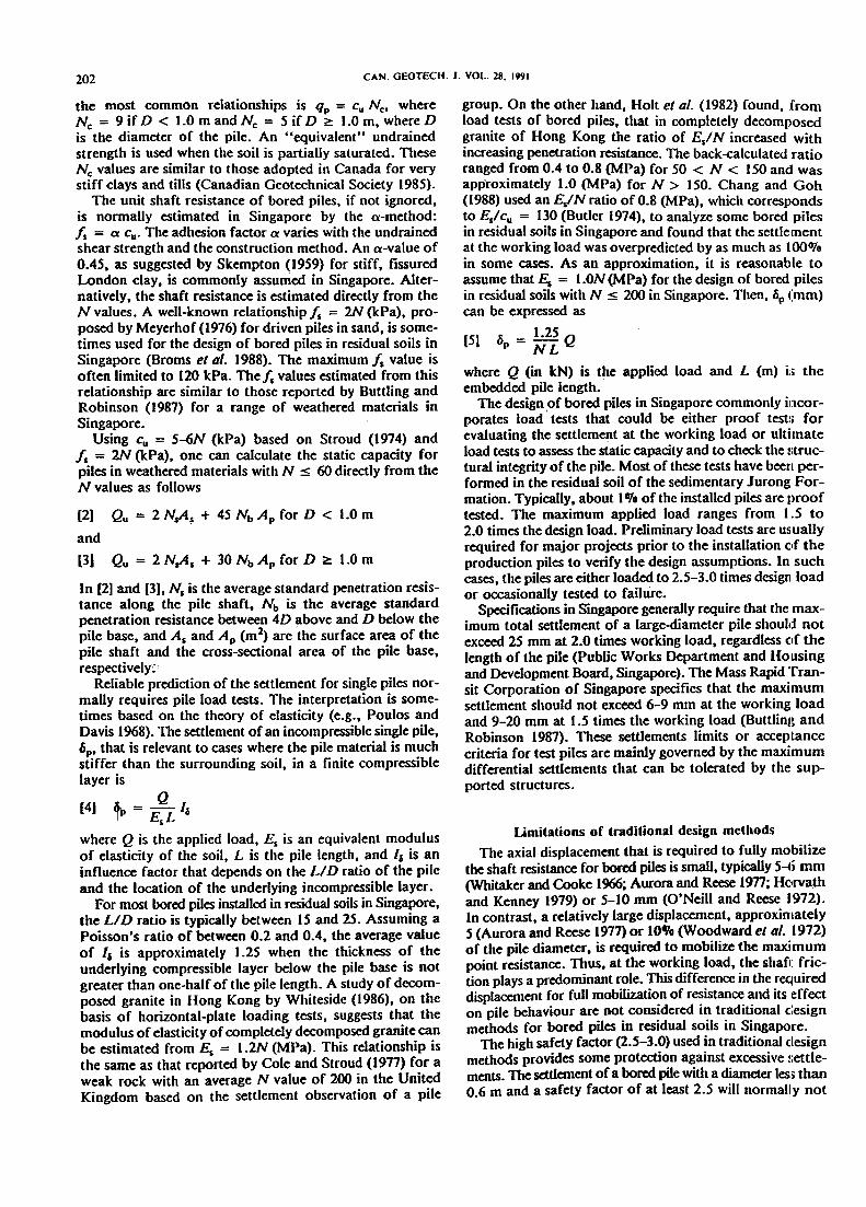
FIG. I. Relationship between unit shaft resistance and standardpenetration resistance.
that the unit shaft resistance for bored piles in the r~jdualsoil of the Jurong Formation increases with increasingpenetration resistance. The scatter of the data also increasesas the penetration resistance increases. Neverthel~;, formaterials with N:s 150-180, an approximate relationshipbetween is and N is[8] is = 2N (kPa)
Note that in Fig. I the shaft resistance, for some of thedata points (marked as open squares) below the fs := 2Nline, has not been fully mobilized. Some data reported carlierby Chang and Goh (1988) for which reliable Nvalues werenot available have been excluded. With the reasonablc: database for bored piles of different diameters and lengths inTables 1 and 2, [8] represents an updated and averagc: cor-relation for bored piles in residual soils in Singapore. Theisl N ratio indicated by [8) is slightly smaller than that,between 2.5 and 2.7 for N:s 120, reported by Toh et a/.(1989) for a weathered sedimentary formation in Malaysia.
It should be noted that the isl N ratio tends to decreasewith increasing N value as the material becomes relativelyhard, with the N value exceeding 150-180. This tendencyof fsl N decreasing with increasing N has also been notedby Toh et a/. (1989). Data collected by Radhakrishnal1 andLeung (1989), primarily for bored piles in highly fractured,"rock..like" materials with N > 200, indicate thatfslN < 1.0, in general. Toh el a/. (1990) suggested th:it thedesign value of fs should not exceed that at N = 200 evenfor bored piles in materials with N > 200. It is re:com-mended that, for N > 150-180, the shaft resistance shouldbe estimated directly from load tests on instrumented piles.
The critical shaft displacement (zJ depends on the inter-face characteristics, or the stiffness of the soil and th4~ unitshaft resistance. The variation in the Zs value is genl~rallysmall, between 4 and 7 mm. As shown in Tables I and 2,the value of Zs is largely independent of the penetrationresistance and the pile diameter. The ratio of is"zs' a
The corresponding load distribution along the pile can alsobe evaluated.
The load-transfer method has the advantage that therequired load-transfer curveS or parameters are directlydetermined or estimated from load tests on instrumentedpiles. In contrast, the elastic method requires substantialidealization and simplifications of the behaviour of the soiland the pile-soil interface. The fmite-element method usuallyrequires a powerful computer and considerable computa-tional time. The construction method, which has a largeeffect on the behaviour of bored piles, is difficult to incor-porate in the latter two methods.
Because of its simplicity, the load-transfer analysis canbe carried out using a microcomputer with minimal costs.A simple computer program AXCOL developed by Meyeret al. (1975) based on the concept proposed by Coyle andReese (1966) is recommended.
Two load-transfer parameters, the ultimate resistance andthe displacement required to fully mobilize this resistance,are required to define the load-transfer curve for each sup-porting stratum (Vijayvergiya 1m). Using parametersdeduced from pile load tests in Singapore and Vijayvergiya'srelationships, Chang and Goh (1988) found that the load-transfer method produced reasonable values with respect toboth the settlement and the load distribution for bored pilesin the residual soil of the Jurong Formation.
The load-transfer parametersThe load-transfer curves are governed by the soil condi-
tions and the construction method. For major projects, loadtests on instrumented piles can provide these curves or thecorresponding parameters. For small projects, however,estimates of these curves have to be made directly from siteinvestigation data, such as the standard penetration resistance.
The relationship between the unit shaft resistance (/s)and the standard penetration resistance (N) based on thedata in Tables 1 and 2 is shown in Fig. 1. The figure indicates

CHANG AND DROMS 207
measure of the stiffness of the pile-soil interface, has beenrelated to the penetration resistance in Fig. 2. The scatterof the results is large, but the data indicate that the ratioof fslls increases with increasing penetration resistance. Anapproximate correlation is
(9) b = N + 17 (kPa/mm)ls 4.25
From [8) and (9), the critical shaft displacement forN ~ 150-180 is then
8.5N[10] N + 17 (mm)
According to [101, Z5 increases from 4 to 7 mm when thestandard penetration resistance increases from IS to 80.
As discussed earlier, a large displacement is required tomobilize fully the point resistance. The corresponding load-transfer parameters, the point resistance (qp) and thecritical point displacement (zp), do not significantly affectthe predicted settlement at the working load, since themobilized point resistance is usually small (Olang and Wong1987). If the point or end-bearing capacity is considered,qp = 30-4SN (kPa) and Zp = 5-100/0 pile diameter willusually be satisfactory for the design of bored piles inresidual soils. The lower limit of qp and the upper limit ofzp should be used if the pile diameter is larger than 1.0 m.
Zs =
Design exampleAn example involving a bored pile with a required
allowable load of 5750 kN serves to illustrate differencesbetween the recommended and the traditional designmethods. The soil conditions are as follows:
2045
Stiff silty clayHard silty clayHard clayey silt to
completely weathered rockCompletely weathered rockHighly weathered rock
75100180
16-20~20
It is assumed that a short-flight auger is used for theexcavation and the concrete is of grade 30, having acharacteristic cube strength of 30 MPa. The maximumallowable settlement of the pile is 5 mm.
From structural considerations, the minimum requiredpile diameter is 1.0 m. The estimated pile length (L) is 23 mat a global factor of safety of 3.0, using a = 0.45 forN < 60, a = 0.3 for N ~ 60 (Skempton 1959), andCu ~ 5N depending on the range of N (Stroud 1974; Coleand Stroud 1977). A pile of larger diameter or greater length(if the end bearing capacity does increase with depth) wouldbe required if the shaft resistance is ignored. The predictedsettlement for a 1.0 m diameter and 23 m long pile is approx-imately 5.0 mm at the working load, according to [5) usinga weighted average value of tIN along the pile shaft.
Figure 3 shows the predicted load-settlement relationshipfor a 1.0 m diameter pile at the proposed site, based on thenew recommended procedure. The load-transfer parameters
were estimated from measured N values using the correla-tions in [8] and [10]. The required pile length is 22 m, (:on-sidering both the settlement and the stability requirements.At L = 22m, the expected settlement, at the design loadof 5750 kN, is about 3.6 mm, which is less than theallowable limit of 5 mm. The corresponding global fa4:torof safety, approximately 2.0, is also adequate, if the ultimatecapacity of the pile is defined as the applied load that t:or-responds to a pile head displacement of between 20 and2S mID on the basis of local acceptance criteria for test piiles.
The ca:mputed load-settlement curve in Fig. 3 shows Ithatthe estimated settlement of the piles at the design load willnot increase significantly if the pile length is reduced from2S to 20 m. Nevertheless, the factor of safety will be sm2llierthan the required value of 2.0 when the length of the pileis less than 22 m. It is -therefore necessary to also specifythe factor of safety against failure, in addition to the maxi-mum allowable settlement, in the design of bored piles inresidual soils (Chang and Goh 1989).
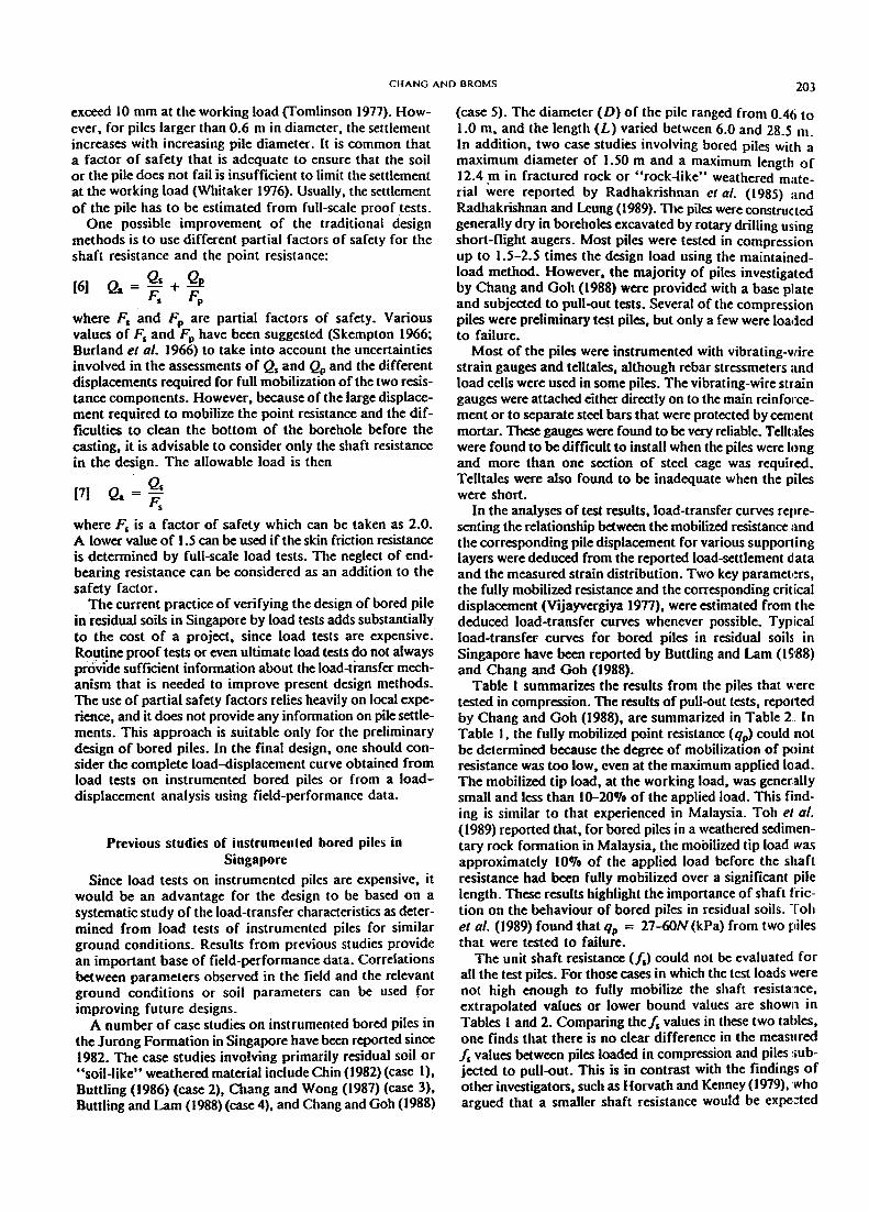
Figure 4 shows the load-distribution curves calcul2ted bythe load-transfer method. The figure clearly indicates theimportance of shaft friction on the behaviour of the pile.The mobilized tip load at the design load increases onlymarginally from 1.6 to 5.3% of the applied load when thepile length is reduced from 25 to 21 m. The reduction ofthe pile length results in an increase of the mobilized sltaftresistance above the pile base. This increase compensatespartially for the loss of shaft resistance along the cutoffsection.
In summary, the traditional design method requires a pilelength of 23 m or greater. The minimum required pile length

208 CAN. GEOTECH. J. VOL. 28. 1991
0 .~I The recommended design procedure using the load-transfer method of analysis can result in safer and moreeconomical solutions, since the complete load-settlementbehaviour of the piles is considered. The resulting sa"ingscan be significant for large projects owing to the redu<:tionof the pile lengths.
2 IStiff silty clay "=20
4
~
6~f I
I Hard silly clay4S
......
"~ 8
g"0 10..&.
.!! 12a.3: 140"in&. 160...0 18
AcknowledgmentsThe authors thank Dr. Anthony Goh for his assistance
in the preparation of an earlier version of this paper, Pro-fessor James Graham for his constructive comments, andProfessor John McNown for his advice on the techmcalwriting.
to completelyweatheced rockN: 75
Completelyweathered rockN : 100
sectionDiameter = 1000 mmEA = 23.56 x 10⁶
Pile length. L = 21 m.L:23mA L=25m
weathered fOCI(= 180 I
0 2 4 6 8 10 12
Axial load, P (MN)
FIG. 4. Load distribution curves.
based on the recommended design procedure using the load-transfer method is 22 m. The difference in the pile length.as illustrated by this example, is relatively small. mainlybecause similar is values have been used in the traditionalmethod and in the recommended design procedure. Thesituation can be more critical in other cases. especially whenthe shaft resistance is underestimated or totallyi"gnored inthe traditional method. The savings in material and construc-tion costs, even for a reduction of the pile length by1.0 m/pile, can be significant for large projects. The recom-mended design procedure has the additional advantages thatit is based on the mechanism of how a pile actually transfersload to the supporting strata and on empirical correlationsobtained from direct measurement of this mechanism.
ConclusionsInsufficient consideration of the load transfer and over-
reliance on pile load tests for verification are responsiblefor the conservative traditional design methods that are pres-ently used in Singapore for bored piles in residual soils.
Results from load tests of instrumented bored piles inSingapore have shown that the sbaft resistancepredominantly governs the behaviour of bored piles in theresidual soil of the Jurong Formation, a finding similar tothose for bored piles in stiff clays and soft rocks elsewhere.
Test results suggest thatfs = 2N (kPa) for the unit shaftresistance and Zs = 8.5 N/(N + 11) (mm) for the criticalshaft displacement for bored piles in weathered materialswith N ~ 150-180. These correlations are specifically forthe residual soil of the Jurong Formation in Singapore.However, it is expected that similar correlations can bederived for other soil conditions.
AURORA, R.R., and REESE, L.C. 1976. Field tests of drilled !:haftsin clay-shales. Proceedings of the 9th International Conferenceon Soil Mechanics and Foundation Engineering, Tokyo, vol. 2,pp.371-376.
BROMS, B.B., CHANG, M.F., and GOH, A.T.C. 1988. Bored pilesin residual soils and weathered rocks in Singapore. Proceedingsof the 1st International Geotechnical Seminar on Deep I"oun-dations on Bored and Auger Piles, Ghent, Belgium, pp. 1'7-34.
BURLAND, J.B., BUTLER, F.G., and DUNICAN, P. 1966. Thebehaviour and design of large diameter bored piles in stiff clay.Proceedings of the Symposium on Large Bored Piles, Institutionof Civil Engineers, London, pp. 51-71.
BU11.ER, F.G. 1974. Heavily overconsolidated clays. Review Ipaperto session Ill. Procedings of Conference on Settlement of ~itruc-tures, Cambridge, pp. 531-578.
BUlTLING, S. 1986. Testing and instrumentation of bored piles.Proceedings of the 4th Nanyang Technological InstituteGeotechnical Seminar on Field Instrumentation and In-situMeasurements, Singapore, pp; 211-218.
BUlTLING, S., and LAM, T.S.K. 1988. Behaviour of someinstrumented rock socket piles. Proceedings of th( 5thAustralian -New Zealand Conference on Geomechanics,Sydney, pp. 526-532.
BUlTLING, S., and ROBINSON, S.A. 1987. Bored piles-desigll1 andtesting. Proceedings of Singapore Mass Rapid Transit Con-ference, Singapore, pp. 155-175.
CANADIAN GEOTECHNICAL SOCIETY.. 1985. Canadian foundationengineering manual. 2nd ed. Canadian Geotechnical Society,Vancouver, B.C.
CHANG, M.F. 1988. In-situ testing of residual soils in Singapore.Proceedings of the 2nd International Conferenc.: onGeomechanics in Tropical Soils, Singapore, vol. I, pp. 97-108.
CHANG, M.F., and GoH, A. T .C. 1988. Behaviour of bored pilesin residual soils and weathered rocks of Singapore. RescarchReport CSE/1988/l7, Nanyang Technological Institute,Singapore. ..
-1989. Design of bored piles considering load transfer.Geotechnical Engineering, 20: 1-18.
CHANG, M.F., and WONG, I.H. 1987. Shaft friction of drilledpiers in weathered rocks. Proceedings of the 6th [ntemal:ionalCongress on Rock Mechanics, Montreal, vol. I, pp. 313-318.
CHIN, Y.K. 1982. Instrumented ultimate load tests on bored piles.The 5th Public Works Department Technical Seminar , Sing~lpore.pp. 1-59.
COLE, K.W., and STROUD, M.A. 1977. Rock socket piles atCoventry Point, Market Way, Coventry. Proceedings of theInstitution of Civil Engineers Symposium on Piles in Weak IRock,London, pp. 47-62.
COYLE, H.M., and REESE, L.C. 1966. Load transfer for axiallyloaded piles in clay. ASCE Journal of the Soil Mechanics andFoundation Division, 92(SM2): 1-26.
GEOLOGICAL SOCIETY ENGINEERING GROUP. 1990. Tropicalresidual soils. Geological Society Engineering Group Wo£king

CHANG AND DRaMS 209
tary ronnation. Proceedings or the 12th International Conrercnceon Soil Mechanics and Foundation Engineering, Rio de Janeirovol. 2, pp. 1073-1078. '
TOMLINSON, M.J. 1977. Pile design and construction practice.View Point Publications, London.
VIJAYVERGIYA, V.N. 1977. Load-settlement characteristics orpiles. Proceedings or Ports '77 Conrerence, Long Beach, CA,pp. 269-284.
WHITAKER, T. 1976. The design of piled roundations. 2nd ed.Pergamon Journals Ltd., Oxrord.
WHITAKER, T., and CooKE, R.W. 1966. An investigation or theshart and base resistance or large bored piles in London clay.Proceedings or the Institution for Civil Engineers Symposiumon Large Bored Piles, London, pp. 7-49.
WHITESIDE, P.G.D. 1986. Horizontal plate loading tests in com-pletely decomposed granite. Hong Kong Engineer, 14(10): 7-13.
WOODWARD, R.J., GANDNER, W.S., and GREER, D.M. 1972.Drilled pier roundations. McGraw-Hili, New York.
YONG, R.N., CHEN, C.K., SELLAPPAH, J., and CHONG, T.5.1985. The characterization or residual soils in Singapore. Pro-ceedings or the 8th Southeast Asian Geotechnical Conrerel1lce,Kuala Lumpur, vol. ,I, pp. 3.19-3.26.
List of symbols
Party Report. Quarterly Journal of Engineering Geology,23: 1-101.
HOLT. D.N., LUMB, P.. and WONG. P.K.K. 1982. Site control andtesting of bored piles at Telford Gardens. and elevated townshipat Kowloon Bay. Hong Kong. Proceedings of the 7th SoutheastAsian Geotcx:tmical Confaence. Hong Kong, vol. I, pp. 349-361.
HORVATH, R.G.. and KENNEY, T.C. 1979. Shaft resistance ofrock-socketed drilled piers. Proceedings of the Symposium onDeep Foundations. ASCE National Convention, Atlanta,pp.183-214.
JANBU, .N. 1967. Settlement calculations based on the tangentmodulus concept. University of Trondheim. Norwegian Instituteof Technology, Bulletin 2.
LI1TLE, A.L. 1969. The engineering classification of residualtropical soils. Proceedings of the 7th International Conferenceon Soil Mechanics and Foundation Engineering. Specialty Ses-sion on Engineering Properties of Lateritic Soils, Mexico, vol. I,
pp.I-IO.MEYER, P .C.. HOLMQUIST. D. V.. and MATLOCK. H. 1975. Com-
puter predictions for axially-loaded piles with nonlinear supports.Proceedings of the 7th Offshore Technology Conference.Houston. Paper 2186. vol. I. pp. 375-387.
MEYERHOF. G.G. 1976. The bearing capacity and settlements ofpile foundations. ASCE Journal of the Geotechnical Engineer-ing Division. 102(GT3): 197-228.
MORTON. K.. and SAYER. P. 1985. Discussion on "A review ofgeology and engineering geology in Singapore." Quarterly Jour-nal of Engineering Goology. 18: 291-293.
O'NEILL. M. W.. and REESE. L.C. 1972. Behavior of bored pilesin Beaumont clay. ASCE Journal of the Soil Mechanics andFoundations Division. 98(SM2): 195-213.
OSIF.RBERG. J.O.. and GILL. S.A. 1973. Load transfa mechanismfor piers socketed in hard soils or rock. Proceedings of the 9thCanadian Rock Mechanics Symposium, Montreal, pp. 235-261.
PI1TS. J. 1984. A review of geology and engineering geology inSingapore. Quarterly Journal of Engin«ring Gcoiogy. 17: 93-101.
POH, K.B.. CHUAH. H.L.. and TAN. S.B. 1985. Residual granitesoil of Singapore. Proceedings of the 8th Southeast AsianGootechnical Conference. Kuala Lumpur, vol. I. pp. 3.1-3.9.
POULOS, H.G.. and DAVIS. E.H. 1968. The settlement behaviourof single axially-loaded incompressible piles and piers.Geotechnique. 18: 351-371.
PuBUC WORKS DEPARTMENT OF SINGAPORE. 1976. Geology of theRepublic of Singapore. Public Works Department. Singapore.
RADHAKRISHNAN. R.. and LEUNG, C.F. 1989. Load transferbehaviour of rock-socketed piles. ASCE Journal of the"Geotechnical Engineering Division. 115(GT6): 755-768.
RADHAKRISHNAN. R.. LEUNG. C.F.. and SUBRAHMANYAM, R. V.1985. Load tests on instrumented large diameter bored piles inweak rock. Proceedings of the 8th Southeast Asian GeotechnicalConference. Kuala Lumpur. vol. I. pp. 2.50-2.53.
SKEMPTON, A. W. 1959. Cast in-situ bored piles in London clay.Geotechnique.9: 153-157.
-1966. Summing up. Proceedings of the Institution of CivilEngineers Symposium on Large Bored Piles, London, p. 155.
STROUD. M.A. 1974. The standard penetration test in insensitiveclays and soft rock. Proceedings of the 1st European Seminaron Penetration Testing. Stockholm. vol. 2:2, pp. 366-375.
TOH, C.T.. 001, T.A., CHIU. H.K.. CHEE. S.K., andTING, W.N.1989. Design parameters for bored piles in a weathered sedimen-
A cross-sectional area of the pile (m 1Ap cross-sectional area of the pile tif (m1As surface area of the pile shaft (m )Cc compression indexCu undrained shear strength (kPa)D diameter of pile (m or mm)E elastic modulus of pile (GPa)Es elastic modulus of soils (MPa)Is, (!s)max unit shaft resistance (kPa)F, Fs. Fp factors of safety4 influence factor for pile settlementm modulus numberL length of pile (m)N standard penetration resistance (blows/O.3 m)Nb average N value at the pile baseNc bearing capacity factorNs avera.ge N value along the pile shaftNw ram sounding resistance (blows/O.2 m)P axial load in pile (kN or MN)Po axial load at the pile top (kN or MN)Q applied load (kN or MN)qp point resistance pressure (kPa)Qa allowable load (kN)Qp point resistance force (kN)Qs total shaft resistance (kN)Qu ultimate pile capacity (kN)Zs critical shaft displacement (mm)zp critical tip displacement (mm)a adhesion factor6p pile settlement (mm)60 pile head movement (mm)