c.g. conn tuba designs from 1880-1940: an …. conn tuba designs from 1880-1940: an investigation of...
TRANSCRIPT

C.G. Conn Tuba Designs from 1880-1940:
An Investigation of Early Tuba Product Lines and Construction Techniques
by
David M. Earll
A Research Paper Presented in Partial Fulfillment
of the Requirements for the Degree
Doctor of Musical Arts
Approved September 2014 by the
Graduate Supervisory Committee:
Deanna Swoboda, Chair
John Ericson
James DeMars
Douglas Yeo
ARIZONA STATE UNIVERSITY
December 2014

i
ABSTRACT
The C.G. Conn instrument manufacturing company is known as one of the most
successful and innovative band instrument manufacturers in the history of the United
States. Many of C.G. Conn's instrument product lines have undergone significant changes
throughout the company's history, especially in the brass family. The C.G. Conn tuba
product lines are no exception to this company's extraordinary success, and have been
significantly redesigned since the company began manufacturing these instruments in
circa 1880. This research project investigates the tuba product lines that C.G. Conn
manufactured between 1880 and 1940. C.G. Conn designed six different tuba product
lines during this timeframe, including an unnamed tuba product line with Stölzel valves,
the Wonder Valve line, the New American line, the Wonder Model line, the 20-J, and the
22-J instrumental product lines. These tuba product lines have been investigated using
extant publications and patent information because the majority of C.G. Conn's internal
records prior to 1970 have been lost. In addition to investigating each of C.G. Conn's
early tuba product lines, this project also explores the particularly anomalous design in
the top-action valve apparatus of the Conn Wonder Model tuba product line. This
anomalous design was implemented in the all of C.G. Conn's top-action tuba and tuba-
like product lines from circa 1890-1940. This author's measurements of period
instruments and analysis of data taken from these measurements indicates that this
anomalous top-action valve apparatus design utilized interchangeable parts with other
front-action C.G. Conn tuba product lines.

ii
ACKNOWLEDGMENTS
The author would like to thank the following individuals and organizations for their
contributions to this project.
Committee Members:
Dr. Deanna Swoboda – Assistant Professor of Tuba and Euphonium –
Arizona State University – Advisor and Committee Chair
Dr. James DeMars – Professor of Music Theory and Composition –
Arizona State University
Dr. John Ericson – Associate Professor of Horn and Brass Area Coordinator –
Arizona State University
Douglas Yeo – Professor of Practice: Trombone – Arizona State University
National Music Museum – University of South Dakota – Vermillion, South Dakota:
Dr. Margaret Downey Banks – Associate Director, Senior Curator of Musical
Instruments, Professor of Music – University of South Dakota –
Advisor of On-Site Research
Supporting Organizations:
2013 Northern Trust/Piper Enrichment Award
U.Discover Summer Scholar Research Program
Additional Thanks:
Samuel Pilafian – Professor of Tuba and Euphonium – Frost School of Music, University
of Miami – Former Advisor and Committee Chair of this Research Project
Dr. Kenneth P. Drobnak – Assistant Professor of Music, Director of Bands –
Northwestern Oklahoma State University

iii
Dr. Steven Sudduth – Assistant Professor of Music, Director of Bands,
Professor of Low Brass – University of the Cumberlands
Special Thanks:
While it would be impossible to thank all of the outstanding individuals who have
been a part of my academic and professional journey, I want to extend my appreciation to
a number of people who have left an irreversible mark on my life for the better. In
particular, I wish to thank my family for their support of my dreams. Mike and Mary
Earll, I couldn’t ask for more loving or supportive parents, and I will always look up to
you both. Josh Earll, you are as supportive as a brother could be, and I always appreciate
your opinions as my sounding board. To Barb and Lyle Earll and to Anne and Frank
Breuker; I could not have asked for four more supportive grandparents and lifelong role
models.
Additionally, I would like to extend a special thanks to my Arizona ‘family,’ who
were there to support me through each step through graduate school. To Kathy Berry and
Leonora Stephanoff, you made me feel like family from the first time we met, and I am
grateful to have been found by two such outstanding ‘Arizona grandmothers.’ To my
friends Susan, Michael, and Tyler McCall, I will always be grateful for having you in my
life as well.
Lastly, I would like to thank all of my music teachers who are not listed above.
Each of you were the inspiration for me to follow my dreams, to work harder than I knew
was possible, and to open a door to a more exciting career than I could have ever hoped
for. Mike Andersen, Rolyn Beaird, Galen Benton, Peter Carlson, Luci Ferrin, Lorenda
Glade, Kelly Jacobsma, Cindy Kemp, Corkey Koerselman, Dr. Larry Mitchell, Dr. Rolf

iv
Olson, Dr. Gary Reeves, and Dr. Stephen Yarbrough: each of you are my heroes and role
models. Thank you for planting the love of music in my life and helping me walk on this
journey to my calling.

v
TABLE OF CONTENTS
Page
INTRODUCTION………………………………………………………………………...1
CHAPTER
1 THE EARLY C.G. CONN TUBA PRODUCT LINES ........................................ 4
Section 1: The Success and Advertisement of Early C.G. Conn Tubas .. 5
Section 2: The First Known C.G. Conn Tuba Product Line ................. 10
Section 3: The C.G. Conn “Wonder Valve” Tuba Product Line .......... 15
Section 4: The C.G. Conn “New American” and
“Wonder Model” Tuba Product Lines .......................................... 21
Section 5: The C.G. Conn 20-J and 22-J Tuba Product Lines .............. 33
2 INVESTIGATION OF THE C.G. CONN TUBA CONSTRUCTION TECHNIQUES
AND DESIGN ............................................................................... 35
Section 6: Review of the Anomalous C.G. Conn Tuba Design ............ 36
Section 7: The Anatomy of Concert Tubas ......................................... 38
Section 8: The Atypical Design of the C.G. Conn Top-Action Tubas .. 45
Section 9: The Influence to Pursue Comparative Measurements.......... 51
Section 10: The Method of Comparative Measurements ..................... 54
Section 11: Outcomes of the Comparative Measurements ................... 56
CONCLUSION..... ........................................................................................................ 58
BIBLIOGRAPHY..... .................................................................................................... 59

vi
Page
APPENDIX
A C.G. CONN TUBA-RELATED PERIODICALS ............................................ 64
B C.G. CONN TUBA-RELATED PATENTS ................................................... 118
C DIAGRAMS OF MEASURMENT POINTS ON FRONT-ACTION TUBAS. 132
D DIAGRAMS OF MEASUREMENT POINTS ON TOP-ACTION TUBAS ... 145
E PHOTOGRAPHS OF PROCEDURES AND INSTRUMENTS ..................... 157
F MEASUREMENTS AND FIELD RESEARCH DATA ................................. 167
G SUPPLEMENTAL IMAGES ........................................................................ 175
H PERMISSION LETTERS ............................................................................. 178

1
INTRODUCTION
The C.G. Conn instrument manufacturing company is recognized as one of the
most successful and innovative band instrument manufacturers in the history of the
United States. The strides this company made in instrument design (particularly in valve
technology, instrument wrap1, and bore diameter expansion)
2 were especially important
to the integration of new concepts in the development of the concert tuba3, which had
been first patented only thirty-nine years before C.G. Conn was founded in 1874.4
Unfortunately, much of the historical documentation regarding the C.G. Conn instrument
manufacturing company’s construction techniques, equipment, and training have been
lost due to factory fires in 1883 and 1910.5 Beyond the loss of these early records, almost
all of C.G. Conn’s historical documents after the factory fire of 1910 were unfortunately
disposed of during a transition in the company’s corporate headquarters during the
1970s.6 Despite the loss of these historical records, it is still possible to investigate this
chapter in the development of the modern tuba through other research methods. The
principal methods used to investigate this timeframe will include examination of extant
period (circa 1880-1940) advertisements and periodicals, analysis of patent information,
1 ‘Wrap’ is a term used in brass instrument manufacturing that is used to discuss the curvature of tubing in an instrument. 2 Jeffrey Paul Hodapp, “The York Tuba : Design Idiosyncrasies that Contribute to its Unique Sound”
(DMA diss., University of Madison-Wisconsin, 2002), 26-44. 3 ‘Concert tubas’ are often simply referred to as tubas, and typically played in a seated position. This
instrument design will be discussed at length throughout this document, and excludes other tuba-like
instruments such as sousaphones, helicons, and bombardons. 4 Margaret Downie Banks, "A Brief History of the Conn Company (1874-present)," National Music
Museum, http://people.usd.edu/~mbanks/CONTENT.html (accessed February 14, 2012). 5 Ibid. 6 Margaret Downie Banks, “The Conn Company Archive,” National Music Museum,
http://orgs.usd.edu/nmm/connarch.html (accessed June 20, 2014).

2
and measurements taken from period tuba models from the instrument collections at the
National Music Museum of Vermillion, South Dakota.
This document investigates the six earliest tuba product lines produced by the
C.G. Conn instrument manufacturing company between approximately 1880 and 1940
and discusses the design of these instrument product lines in Chapter 1. The first two tuba
product lines were only offered by C.G. Conn over the course of approximately ten years
which is a rather brief period of time when compared to this company’s third design.
C.G. Conn’s third tuba design was in production for nearly fifty years. The two tuba
product lines of this third design, based on two patents granted to Charles Gerard Conn in
1889 and 1890, were first made available for purchase circa 1890 and became the basic
designs for all of C.G. Conn’s concert tuba, euphonium, baritone, tenor horn, and alto
horn7 product lines manufactured by the C.G. Conn instrument manufacturing company
until 1940.8 C.G. Conn’s next two tuba product lines were released in roughly 1940, and
implemented new designs which differentiated these instruments significantly from the
earlier tuba product lines.9
The two tuba product lines of the third C.G. Conn design, called the “New
American Model” and “New Wonder Model” tubas,10
were highly endorsed by leading
artists of the time11
and were considered to demonstrate high quality in their
7 This list of instruments (the euphonium, baritone, tenor horn, and alto horn) will often be referred to as
‘tuba-like’ instruments throughout this document due to be construction similarities that these instruments
exhibit, especially in early C.G. Conn instrument design. 8 C.G. Conn, Selling Points and Testimonials “Bass.” (Musical Instrument Manufacturers Archive Conn
Catalogs 1888-1949, National Music Museum, 1923-1924), 5-18. 9 C.G. Conn, Conn Band and Orchestra Instruments, (Musical Instrument Manufacturers Archive Conn
Catalogs 1888-1949, National Music Museum, September 1940), 36-37. 10 C.G. Conn, Wonder and American Model Valve Instruments. (Musical Instrument Manufacturers
Archive Conn Catalogs 1888-1949, National Music Museum, 1895). 11 Conn, Selling Points and Testimonials “Bass,” 1 22-36.
3
construction.12
While these tuba product lines showed immense success in the highly
competitive instrument sales market of the United States during their time of
manufacture,13
the New Wonder Model tuba and tuba-like product lines were built with a
highly anomalous valve apparatus design when compared to many contemporary and
modern tuba models. This atypical design and the potential reasons for such a design in
the New Wonder Model tubas and tuba-like product lines will be discussed at length in
Chapter 2, including a new study of the apparent use of interchangeable parts between the
New Wonder Model tuba product lines and the New American Model tuba product lines.
12 John Joseph Swain, “A Catalog of the E-flat Tubas in the Arne B. Larson Collection at the University of
South Dakota.” (PhD diss., Michigan State University, 1985), 221. 13 Hodapp, 7.

4
CHAPTER 1
THE EARLY C.G. CONN TUBA PRODUCT LINES

5
SECTION 1: THE SUCCESS AND ADVERTISEMENT OF EARLY C.G. CONN
TUBAS
The C.G. Conn instrument manufacturing company is well known for its
innovative and competitive role in the early environment of band instrument construction
and sales in the United States. Although this company originally designed and sold
cornets after their foundation in 1874, C.G. Conn quickly became one of the most
competitive distributors of nearly every band instrument and was endorsed by musical
artists from both the United States and abroad.14
The C.G. Conn tuba product lines were
no exception in this company’s success, and were as heavily endorsed by artists as the
cornets and trumpets with which C.G. Conn established its early national prestige.15
The first three tuba product lines that the C.G. Conn instrument manufacturing
company designed and manufactured were available from approximately 1880 to 1940.
Many of these tuba models were a common fixture in many of the preeminent concert
bands and orchestras and the choice of many tuba artists throughout the United States.16
Additionally, these tuba product lines were able to maintain a considerable amount of
success during this timeframe when many instrument manufacturing companies were
vying for a place in the competitive instrument market in the United States. Companies
such as York & Sons, H.N. White, Holton, and the Grand Rapids Instrument Company
were all simultaneously working to secure their individual successes17
alongside C.G.
Conn in this unpredictable period in instrument manufacturing history, and each of these
popular manufacturers witnessed other young companies struggle and fail to survive in
14 Swain, 271. 15
Conn, Selling Points and Testimonials “Bass,” 22-36. 16 Ibid. 1 22-36. 17 Hodapp, 4-10.

6
such a competitive and quickly evolving market.18
The source of the C.G. Conn
instrument manufacturing company’s success in sales during this timeframe is likely a
culmination of a multifaceted and well-managed business plan that was adjusted carefully
throughout this company’s development19
coupled with C.G. Conn’s commitment to the
quality of their instrumental products through innovative and adaptive construction
techniques.20
The C.G. Conn instrument manufacturing company was not only innovative in
construction techniques but was at the forefront of marketing and advertising during this
these early years of instrument manufacturing and sales in the United States.21
Like many
companies of this era, C.G. Conn initially worked as a mail-order business,
predominantly distributing full product catalogs that contained brief descriptions of their
instruments and some reviews from notable artists of the era.22
In addition to these full
product catalogs, C.G. Conn began to release a publication titled C.G. Conn’s Truth23
in
September of 1890 and kept these periodicals in publication into the 1940s.24
Unlike a
typical mail-order catalog, the C.G. Conn’s Truth periodicals were filled with stories,
endorsements, images, and anecdotes about C.G. Conn instruments. Many of these
periodicals included success stories of ensembles comprised entirely, or at least in
18 Swain 267-274. 19 Swain, 270-272. 20 Conn, Selling Points and Testimonials “Bass,” 2-4. 21 Trevor Herbert, "Selling brass instruments: The commercial imaging of brass instruments (1830-1930)
and its cultural messages," Music In Art: International Journal for Music Iconography 29, no. 1-2 (March
1, 2004): 213
http://web.b.ebscohost.com.ezproxy1.lib.asu.edu/ehost/pdfviewer/pdfviewer?vid=6&sid=2e2fecaa-0437-
4d20-a9d7-a0ef7279b85d%40sessionmgr112&hid=122 (accessed August 18, 2014). 22 Swain, 271. 23 Sometimes referred to as the C.G. Conn Musical Truth, Conn’s Truth, or Conn’s Musical Truth. 24 Deborah Check Reeves, “C.G. Conn’s Double-Wall Wonder Clarinets.” National Music Museum.
http://orgs.usd.edu/nmm/Clarinets/Conn/DoubleWallClarinets/ConnDblWallClarinetsBanks.html (accessed
July 12, 2014)

7
majority, of C.G. Conn instrument players, humorous stories from these musicians, and
sections devoted to endorsements of specific instruments by players and conductors in
both recognized and budding ensembles throughout the United States and even
occasionally from abroad.25
While the C.G. Conn’s Truth publications were seemingly
designed to be for the entertainment and enrichment of a musically savvy audience, the
periodical also included pricing and ordering information for the instrumental products
that were endorsed in each issue. This new form of marketing periodical demonstrated
C.G. Conn’s versatility and ingenuity in the competitive marketing environment that
evolved around musical instrument sales and construction in the United States during the
late 1800s. Several examples of the imagery, prose, and endorsements taken from a C.G.
Conn’s Truth may be seen in further detail in Appendix A.
Beginning in the 1920s, the C.G. Conn instrument manufacturing company also
began to publish a series of instrument-specific catalogs and pamphlets for each of the
C.G. Conn band instrument product lines, although they had been publishing
cornet/trumpet-specific marketing materials as early as the 1890s. These instrument-
specific catalogs were extensive collections of high-fidelity images, construction
information, dimensions, accessories, advertisements, and endorsements of the
instrument featured within each publication. The endorsement sections of these
instrument-specific catalogs were similar in content to the endorsements found in many
of the C.G. Conn Truth periodicals, but were typically much more extensive and allowed
for greater focus on each instrument’s most renowned artists as well as budding artists
25 C.G. Conn, C.G. Conn’s Truth Vol. 5, No. 7 (Musical Instrument Manufacturers Archive Conn Musical
Truth 1897-1918, National Music Museum, November 1903), 26-27.

8
throughout the United States.26
The instrument-specific pamphlets utilized some of the
images and advertisements used in the instrument-specific catalogs, but were
considerably limited in length and as such focused on basic product lines and ordering
information.27
These instrument-specific marketing materials served as a targeted
marketing tool for the C.G. Conn instrument manufacturing company and allowed for the
general catalogs to be less cumbersome. The instrument-specific marketing materials
provided separate but considerably detailed information to each of their specific
instrumental clientele. An example of a tuba-specific catalog (1923-1924) and several
selections from a euphonium-specific (1921) catalog from this period of advertisement
can be seen in further detail in Appendix A, figures A-4 and A-5.
While C.G. Conn’s marketing expertise and diversity in advertisements likely
played a major role in this company’s overall success in the competitive musical
instrument trade of the early 1900s, C.G. Conn was also known for the remarkable
quality of their instruments. C.G. Conn’s early tuba product lines were one of many
product lines that were standards in the musical instrument industry and were known to
have a very high quality of construction which likely contributed to their success.28
In
particular, the two tuba product lines that were patented and manufactured by C.G. Conn
in 1889 and 1890 became the basic designs for all of this company’s concert tuba,
26 Conn, Selling Points and Testimonials “Bass,” 22-36. 27 C.G. Conn, French Horn, Mellophone, Alto (Musical Instrument Manufacturers Archive Conn Catalogs
1888-1949, National Music Museum, ca. 1927), 16. 28 Hodapp, 6-8.

9
euphonium, baritone, and alto horn29
product lines until approximately 1940.30
Each of
the separate instrumental product lines that utilized these two early designs was also quite
successful in the competitive market of musical instrument sales in the United States,31
at
least in part due to the high level of quality in construction for which C.G. Conn became
so well known.32
29 Details of each of these instrumental product lines can be seen in further detail in Appendix A. 30 Conn, C.G. Conn’s Truth Vol. 5, No. 7, 18-27. 31 Hodapp, 6-8. 32 Swain, 221 271.

10
SECTION 2: THE FIRST KNOWN C.G. CONN TUBA PRODUCT LINE
The first known C.G. Conn tuba product was made available as early as 1879,33
and the design included a modified Stölzel valve for which Charles Gerard Conn received
a patent on November 1, 1881.34
Stölzel valves are an early variety of piston valve
developed originally by Henrich Stölzel as early as 1814. Dr. Sabine Klaus states the
following in her writing about the elements of brass instrument construction:
The main difference between the Stölzel valve and the [modern] Périnet35
[…] valves is that the main tubing enters the piston from below. Two
different Stölzel valve models can be distinguished. In the "early model,"
the piston is guided and the spring is stopped by a horizontal screw, going
through the outer casing. In the "later model," the spring is enclosed in a
barrel; therefore, no screw is visible at the valve casing. Guidance is
provided by a key fitting in a groove or keyway at the valve casing.36
The Stölzel valve featured in this tuba model’s design would be classified as the later
model mentioned above.37
Further details of this modified Stölzel valve patent can be
found in Appendix B, in figure B-1.
In addition to this tuba model’s unique implementation of modified Stölzel
valves, this model also featured a noteworthy design which causes the instrument’s lead-
pipe to travel behind the valve apparatus and form a hand grip for its player. The early
Stölzel valve tuba model also featured engraved metal touch-pieces on the valves, rather
than the inlaid mother-of-pearl touch-pieces which became C.G. Conn’s standard
33 Tuba pitched in E-flat by C.G. Conn, Serial Number 4037, NMM 5,892, Musical Instrument Collection,
National Music Museum, The University of South Dakota, Vermillion, SD, ca. 1880-1881. 34 Charles G. Conn, Piston-Valve Musical Instrument, US Patent No. 249,012, filed April 2, 1881, and
issued November 1,1881. 35 The Périnet valve will be discussed at length in Section 3. 36 Sabine Klaus, “Elements of Brass Instrument Construction,” National Music Museum,
http://orgs.usd.edu/nmm/UtleyPages/Utleyfaq/brassfaq.html (accessed July 14, 2014). 37 Charles G. Conn, Piston-Valve Musical Instrument, US Patent No. 249,012, filed April 2, 1881, and
issued November 1,1881.

11
accoutrement for brass instrument product lines starting as early as 1888. 38
This tuba
model was available in the key of E-flat with a top-action39
valve assembly, but it is
unlikely this design was also available in the key of B-flat.40
The loss of so many early
C.G. Conn records due to factory fires in 1883 and 1910 has left the name of this product
line a mystery even though it was likely available for between roughly six and ten
years.41
It is possible that this tuba model was advertised during this timeframe, but any
extant periodicals available from 1879-1888 do not reference this line of tuba model. It
could be that this tuba product line was available only by request until C.G. Conn
released the company’s next tuba product lines in approximately 1888.
This first tuba model with Stölzel valves shares very few design characteristics
with the product lines patented in 1889 and 1890 which were mentioned above, possibly
due to the tightness of wrap that Stölzel valves can cause in tuba design when compared
to Périnet pistons. While an image of this tuba model was not available in any C.G. Conn
periodicals, an extraction of an image from Charles Gerard Conn’s United States patent
No. 249,012 can be seen below in figure 2.1. Unfortunately, this patent diagram is not
entirely accurate to the final design of this instrument. The lead-pipe construction of this
tuba model must have been modified at some time after this patent was submitted. This
tuba model’s final design lengthened the lead-pipe section of the instrument to enter into
the third valve casing, rather than the first valve entry that is shown below. Aside from
38 Tuba pitched in E-flat by C.G. Conn, Serial Number 4037, NMM 5,892, Musical Instrument Collection,
National Music Museum, The University of South Dakota, Vermillion, SD, ca. 1880-1881. 39 The term ‘action’ refers to the placement of valves on a tuba, which are most typically listed as ‘top-
action/right-facing’ and ‘front-action/left-facing.’ This common tuba construction variable will be
discussed at length later in this document. 40 C.G. Conn, C.G. Conn – Solo and Band Instruments Catalog, (Musical Instrument Manufacturers
Archive Conn Catalogs 1888-1949, National Music Museum, 1888). 41 Banks, “The Conn Company Archive.”

12
construction difference in the lead-pipe, the remainder of this basic design is quite similar
to the single C.G. Conn Stölzel valve tuba model which is in the musical instrument
collection of the National Music Museum in Vermillion, South Dakota.42
Figure 2.1:
43 The first known C.G. Conn tuba product
with Stölzel valves. Model name unknown, pitched in
E-flat, available circa 1880-1888.
42 Tuba pitched in E-flat by C.G. Conn, Serial Number 4037, NMM 5,892, Musical Instrument Collection,
National Music Museum, The University of South Dakota, Vermillion, SD, ca. 1880-1881. 43 Charles G. Conn, Piston-Valve Musical Instrument, US Patent No. 249,012, filed April 2, 1881, and
issued November 1,1881.

13
It is tempting to consider that this first C.G. Conn tuba model with Stölzel valves
may have been imported or designed using European patents due to a popular trend in
early musical instrument manufacturing in the United States. Not only is the design of
this tuba model so fundamentally dissimilar in design from all of C.G. Conn’s subsequent
low brass product lines, the presence of a traditionally German Stölzel valve on a tuba
manufactured in the United States is also considerably anomalous. The practice of
importing and then signing unmarked instruments from Europe was fairly popular with
early American instrument manufacturers, especially when these manufacturers were in
the first stages of selling new instrument product lines.44
While this practice was fairly
popular in this timeframe, and certainly would have been a viable option for the staff at
the C.G. Conn instrument manufacturing company, there is enough extant documentation
to provide a strong case that this tuba model was indeed designed and manufactured by
C.G. Conn. The strongest argument that this tuba model was designed and manufactured
by C.G. Conn is found in Charles Gerard Conn’s patent from 1881 to modify Stölzel
valves, specifically in the context of tuba and valve trombone product lines.45
An
engraving on the bell of this tuba model in the musical instrument collection of the
National Music Museum which claimed that the instruments were “made by C.G. Conn
[of] Elkhart [Indiana]” 46
serves as an additional, if somewhat less credible, sample of
evidence that this instrument was designed and manufactured in the United States,
because many of the other musical instrument manufacturers that were importing and
44 Swain, 271. 45 Charles G. Conn, Piston-Valve Musical Instrument, US Patent No. 249,012, filed April 2, 1881, and
issued November 1,1881. 46 Tuba pitched in E-flat by C.G. Conn, Serial Number 4037, NMM 5,892, Musical Instrument Collection,
National Music Museum, The University of South Dakota, Vermillion, SD, ca. 1880-1881.

14
signing unmarked instruments would make similar claims.47
Particularly with C.G.
Conn’s patent information as support of this tuba model’s design, this tuba model was
most likely designed and constructed by C.G. Conn in the United States rather than being
imported despite this tuba product line’s somewhat anomalous design and the popularity
of the this importation trend.
47 Swain, 271-272.

15
SECTION 3: THE C.G. CONN “WONDER VALVE” TUBA PRODUCT LINE
The next C.G. Conn tuba product lines which were regularly advertised and made
available for sale from approximately 1888-1890 are also unlike all of the later C.G.
Conn tuba, euphonium, baritone, and alto horn product lines. These two new tuba product
lines were titled the “New Model Wonder Valve Double Bb Bass”48
model and the “Bell
Up Wonder Valve Eb Bass,” model, and featured top-action valve assembly with bottom-
sprung Périnet piston valves.49
Périnet piston valves are one of the most common piston
valves found on modern brass instruments, and are described by Dr. Sabine Klaus in her
writings on brass instrument construction:
The Périnet valve is named after François Périnet, the Parisian who
invented this type of piston valve in 1838 and patented it the following
year. The valve loops are arranged in such a way that the inlet tubing is
positioned on a different level than the outlet tubing. The piston is held at
rest by a spring, which is placed either on top (top-sprung) or below
(bottom-sprung) the piston. The Périnet valve is now the standard for
trumpets in most countries (except Germany and Austria), and is often
simply called the ‘piston valve.’50
Both of these tuba models were part of a series of instrument product lines that C.G.
Conn marketed as the “Wonder Valve Band Instruments.” Alto horns, tenor horns,
baritones, euphoniums, tubas, and helicons were all advertised as Wonder Valve
instruments in this 1888 C.G. Conn catalog,51
and it is likely that each of these
instrumental product lines included a design from the Périnet valve modification patent
which was issued to Charles Gerard Conn on June 15, 1886. Initially this patent seems to
indicate this valve modification is intended to be implemented in cornets, but Conn states
48 Tubas in this timeframe were often referred to as basses, brass basses, or even blow basses. 49 Conn, C.G. Conn – Solo and Band Instruments Catalog. 50 Sabine Klaus, “Elements of Brass Instrument Construction.” 51 Conn, C.G. Conn – Solo and Band Instruments Catalog.
16
in the specifications of this new technology that the invention would be utilized in the
“improvements in cornets and other piston-valve musical instruments.”52
C.G. Conn’s
modification of the Périnet piston valve for this technology’s implementation in multiple
product lines is reminiscent of the efforts made in the earlier Stölzel valve modifications
in 1881.53
This modified Périnet piston valve design may be seen in further detail in
Appendix B in figure B-2.
The Bell Up Wonder Valve Eb Bass model was listed in an 1888 C.G. Conn
catalog as being “patented in Europe and America,”54
which is a further indicator that this
tuba model was developed and modified from existing patents much like the Stölzel
valve patent that C.G. Conn acquired earlier in 1881.55
The Stölzel valve tuba model that
C.G. Conn offered previously was most likely replaced by this new Wonder Valve E-flat
tuba model, as there no other mention of the previous Stölzel valve model in this or other
extant periodicals from circa 1888. The Wonder Valve Eb Bass was available for
purchase with three valves, although it is possible that a fourth valve could have been
added because this was available on other tuba and euphonium Wonder Valve products in
the same 1888 C.G. Conn catalog.56
An image of the Bell Up Wonder Valve Eb Bass
tuba model taken from a C.G. Conn Catalog published in 1888 is shown below in figure
3.1.
52 Charles G. Conn, Cornet, US Patent No. 343,888, filed August 28, 1885, and issued June 15, 1886. 53 Charles G. Conn, Piston-Valve Musical Instrument, US Patent No. 249,012, filed April 2, 1881, and
issued November 1,1881. 54 Conn, C.G. Conn – Solo and Band Instruments Catalog. 55 Charles G. Conn, Piston-Valve Musical Instrument, US Patent No. 249,012, filed April 2, 1881, and
issued November 1,1881. 56 Conn, C.G. Conn – Solo and Band Instruments Catalog.
17
The New Model Wonder Valve Double Bb Bass was listed as “patented April 15,
1886,” in a C.G. Conn catalog from 1888,57
but no records of any patent extended to
Charles Gerard Conn on this date can currently be found. It is feasible that this printing of
“April 15” was a mistake in the C.G. Conn catalog, and that the patent utilized in the
construction of this new tuba model in the key of B-flat was in fact the modified Périnet
valve patent that Conn was awarded on June 15, 1886.58
This is the most probable patent
used considering that the New Wonder Model Valve Double Bb Bass was part of the
Wonder Valve product line, which featured this same valve technology on each of the
other tuba-like instruments. This tuba model is also the only Wonder Valve product listed
in this catalog without a claim of “patented in the United States and Europe,” which
might indicate that this particular model of B-flat tuba was an initial design or prototype
for a new tuba product line. This concept that the New Model Wonder Valve Double Bb
Bass may have been a prototype seems feasible because the Wonder Valve instruments
were available for only four years or less before being replaced permanently with two
new tuba designs which stayed in production for roughly 50 years. The New Model
Wonder Valve Double Bb Bass is also likely the first B-flat tuba model that C.G. Conn
offered, as the advertisement claims that this new model was designed:
In response to a demand for a Bass [Tuba] with more volume of tone and
capable of greater resources than the Eb Bass, I have constructed a BBb
Bass of light weight, convenient and handy proportions which can be used
by any bass player with ordinary lung capacity. The use of this instrument
will prove invaluable to bands of more than 18 persons.59
57 Ibid. 58 Charles G. Conn, Cornet, US Patent No. 343,888, filed August 28, 1885, and issued June 15, 1886. 59 Conn, C.G. Conn – Solo and Band Instruments Catalog.

18
Each of the instruments within the Wonder Valve series were also designed to
incorporate the primary tuning slide before the valve apparatus,60
which is atypical for the
construction and design techniques of many other tubas and tuba-like instruments made
in the United States during this timeframe. Most other tuba models from competing
manufacturers featured a design which placed the primary tuning slide of the instrument
after the valve apparatus, which tended to allow for a more rapid expansion of the tuba
model’s bore after the valve apparatus.61
The New Model Wonder Valve Double Bb Bass
was available with either three or four valves in this 1888 catalog, and was also available
with “extra engraving.”62
An artistic interpretation of this extra engraving option on the
bell of these instruments can be seen below in figures 3.1 and 3.2. Images of the both the
Bell Up Wonder Valve Eb Bass and the New Model Wonder Valve Double Bb Bass
taken from a C.G. Conn Catalog published in 1888 is pictured below in figures 3.1 and
3.2.
60 Ibid. 61 Swain, 221. 62 Conn, C.G. Conn – Solo and Band Instruments Catalog.
19
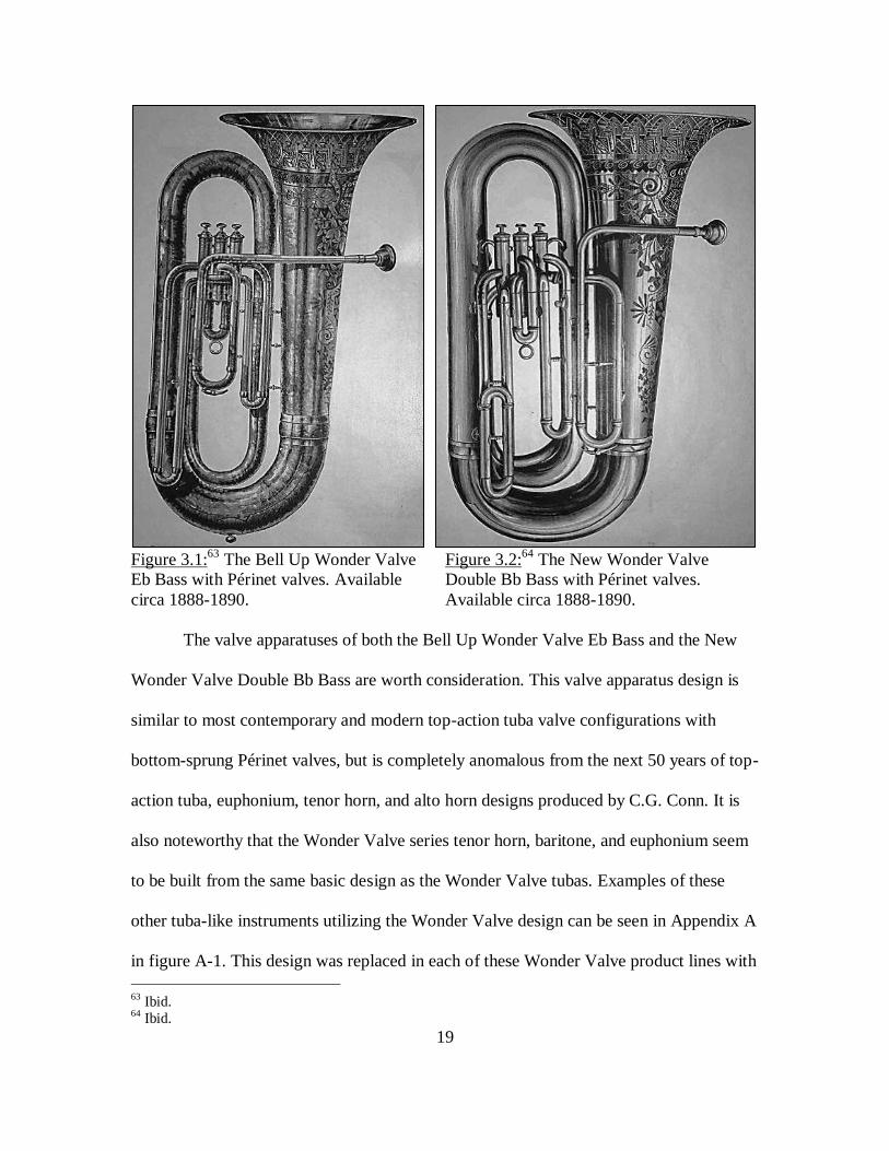
Figure 3.1:
63 The Bell Up Wonder Valve Figure 3.2:
64 The New Wonder Valve
Eb Bass with Périnet valves. Available Double Bb Bass with Périnet valves.
circa 1888-1890. Available circa 1888-1890.
The valve apparatuses of both the Bell Up Wonder Valve Eb Bass and the New
Wonder Valve Double Bb Bass are worth consideration. This valve apparatus design is
similar to most contemporary and modern top-action tuba valve configurations with
bottom-sprung Périnet valves, but is completely anomalous from the next 50 years of top-
action tuba, euphonium, tenor horn, and alto horn designs produced by C.G. Conn. It is
also noteworthy that the Wonder Valve series tenor horn, baritone, and euphonium seem
to be built from the same basic design as the Wonder Valve tubas. Examples of these
other tuba-like instruments utilizing the Wonder Valve design can be seen in Appendix A
in figure A-1. This design was replaced in each of these Wonder Valve product lines with
63 Ibid. 64 Ibid.
20
C.G. Conn’s new patents and product lines released in approximately 1890.65
This
significant disparity in construction between this traditional design and C.G. Conn’s next
top-action design will be discussed at length in several later sections of this document.
As mentioned above, the design of the Wonder Valve tuba product lines differ
from the early Stölzel valve model and C.G. Conn’s next series of tuba product lines.
Most notably, the valve apparatus design of each of these product lines implemented
different technologies designed from three different patents.66
Additionally, each of these
three tuba product lines were constructed with different dimensions in their bells and
outer bough67
structures.68
These disparities in design indicate that it is unlikely that any
significant construction components were reutilized or shared between the first three top-
action C.G. Conn tuba product lines.
65 C.G. Conn, Wonder and American Model Valve Instruments, (Musical Instrument Manufacturers
Archive Conn Catalogs 1888-1949, National Music Museum, 1895). 66 See Appendix B for additional information regarding these valve technology patents. 67 “Boughs” refer to the loops of tubing that are found between the valve apparatus and bell section of
tubas. These boughs often form the outer shape of the instrument. Boughs are also referred to as bows or
loops in some writings. 68 Height (also referred to as ‘length’ in some publications) was the greatest variable, as can be seen in
Appendix A.

21
SECTION 4: THE C.G. CONN “NEW AMERICAN” AND “WONDER MODEL”
TUBA PRODUCT LINES
The next two tuba product lines offered by C.G. Conn were first made available
for purchase in approximately 1890, and the designs for these products immediately
replaced all of the preexisting tuba and tuba-like instrument models that were
manufactured by C.G. Conn. These two product lines were called the “New American
Model” and the “Wonder Model” tubas, and marked the first time that C.G. Conn offered
both front-action (the New American Model) and top-action (the Wonder Model) tubas
and tuba-like instruments. The New American Model tubas were the first known front-
action instruments made available by C.G. Conn, and were likely very popular due to the
general preference that tubists have for front-action instruments.69
Each of these designs
featured bottom-sprung Périnet valves and was initially offered with the primary tuning
slides located after the valve apparatus.70
These two new C.G. Conn tuba models were
also available for purchase from an 1895 C.G. Conn Catalog in a variety of finishes and
with various accessories, but it is worth noting that each of the two separate models could
be purchased for the same price. This same catalog also lists the basic dimensions of each
of these separate models as interchangeable, saying that the each of the tuba models:
Weigh[…] 11 ¼ pounds, [have a] length from edge of [the] bell to [the]
bass of the largest bend [of] 30 inches; width [of the instrument] across at
[the] valves [of] 14 inches, diameter of [the] bell, 19 ½ inches.71
Once C.G. Conn secured these patents for the New American Model in 188972
and the Wonder Model in 1890,73
they continued to manufacture tuba product lines that
69 Swain, 177 70 C.G. Conn, Wonder and American Model Valve Instruments. 71 Ibid.

22
were simple variations on these basic models for approximately the next fifty years. In
fact, these two initial product lines implemented a design which became the basis of all
the other tuba,74
euphonium,75
and alto/tenor horn76
product lines manufactured by the
C.G. Conn instrument manufacturing company until 1940.77
The basic design and the
similarities of these other tuba-like products can be seen in further detail in Appendix A,
figures A-4, A-5, and A-6, and the patents for these two new C.G. Conn instrumental
product lines can be seen in Appendix B, figures B-3 and B-4. The New American Model
and Wonder Model tubas can be seen below in figure 4.1 and 4.2.
72 Charles G. Conn, Musical Wind Instrument, US Patent No. 405,395, filed November 30, 1888, and
issued June 18, 1889. 73 Charles G. Conn, Musical Wind Instrument, US Patent No. 436,696, filed February 6, 1890, and issued
September 16, 1890. 74 Conn, Selling Points and Testimonials “Bass,” 3-18. 75 C.G. Conn, Baritones and Euphoniums, (Musical Instrument Manufacturers Archive Conn Catalogs
1888-1949, C-778, National Music Museum, January 1921). 76 Conn, French Horn, Mellophone, Alto. 77 Conn, Conn Band and Orchestra Instruments, 36-37.

23
Figure 4.1:
78 The New American Model. Figure 4.2:
79 The Wonder Model Tuba.
Tuba. Front-action Périnet valves, Top-action Périnet valves, originally pitched
originally pitched in E-flat, but later in E-flat, but later offered in B-flat. Circa
offered in B-flat. Circa 1890 1890.
The New American Model tubas, which will hereafter be referred to as American
Model tubas, were built with a fairly standard front-action valve apparatus design80
when
compared to other contemporary tubas manufactured in the United States.81
While the
first advertisement of these American Model tubas offered them only in the key of E-flat,
they were available in both the keys of B-flat and E-flat within three to five years.82
According to the American Model instrument patent, the American Model tubas were
designed to allow for a fourth valve to be easily integrated to these instruments during the
78 Conn, Wonder and American Model Valve Instruments. 79 Ibid. 80 Swain, 150 170 177. 81 Clifford Bevan, The Tuba Family 2nd Edition, (Winchester, England: Piccolo Press, 2000), 355. 82 Conn, C.G. Conn’s Truth Vol. 5, No. 7, 26.

24
construction process.83
While this fourth valve option was not initially advertised in their
1895 advertisement, C.G. Conn made a common practice of listing this in later catalogs.84
The early advertisements of the American Model tuba also made a definite appeal to their
target audience’s sense of nationalism, with endorsements such as “invented and patented
by an American, manufactured by American workmen, and immensely popular with
American bandsmen and musicians.”85
While these front-action tubas employed a
standard valve apparatus, the outer bough structure of these instruments was considerably
more open in wrap86
than many of the other competitive contemporary front-action tuba
models.87
While the basic design of the C.G. Conn American Model tubas remained
unchanged for approximately the next 50 years, the subsequent models built using this
design underwent many minor changes in model name, size, and bore expansion.88
Many
of these additional front-action concert tuba and tuba-like instrument models released
during this construction period can be seen in further detail in Appendix A.
While the design of the front-action valve apparatus of the C.G. Conn American
Model tubas was standard when compared to contemporary competitive tuba models, the
top-action valve apparatus of the C.G. Conn Wonder Model tubas was an absolute
anomaly and perhaps the most notably unique design that C.G. Conn has implemented in
the history of this company’s tuba product lines.89
This top-action valve apparatus
featured tubing which ascended upwards out of the valves and then doubled back down,
83 Charles G. Conn, Musical Wind Instrument, US Patent No. 405,395, filed November 30, 1888, and
issued June 18, 1889. 84 Conn, Selling Points and Testimonials “Bass,” 13-18. 85 Conn, Wonder and American Model Valve Instruments. 86 ‘Open in wrap’ means that these tubas were designed to incorporate gradual curves of the instrument’s
main tube and valve tubing. This type of construction is most often referred to as open wrap. 87 Swain, 120 150. 88 Conn, Selling Points and Testimonials “Bass,” 5-18. 89 Swain, 126.
25
forming an oval- or square-shaped section of tubing for each of the valve tuning slides
and valve tubing. This square-like shape in the valve tubing was most prominent in the
first and third valve tubing of C.G. Conn’s top-action E-flat tubas, but was pronounced in
all three sections of valve tubing on their B-flat tubas. The 1895 C.G. Conn catalog
known for featuring the Wonder Model tuba,90
and the 1890 patent for Conn Wonder
Model instruments, claims that this valve apparatus arrangement will “prevent the
accumulation of water in valve slides”91
and be implemented in “alto [horns], tenor
[horns], baritones, euphoniums, and basses [tubas] of all kinds.”92
Dr. John Swain wrote about this “rather special valve slide tubing arrangement”
as well, mentioning that such a design implemented in the valve apparatus would allow
the tubing of the third valve to be “especially protected by the main coil [bough],” which
could have been an additional consideration in the design of the C.G. Conn Wonder
Model tubas.93
Another possibility that will be explored at length in several later sections
of this document is that this top-action valve tubing apparatus was designed in particular
to be interchanged with the valve tubing of C.G. Conn’s front-action valve apparatus
product lines as a means of streamlining the construction process of these two separate
instrument designs. An expanded image of one valve and valve tubing from the C.G.
Conn Wonder Model tuba valve apparatus is shown below in figure 4.3 and may be
compared with another expanded image of a more standard top-action valve that was
90 Conn, Wonder and American Model Valve Instruments. 91 Charles G. Conn, Musical Wind Instrument, US Patent No. 436,696, filed February 6, 1890, and issued
September 16, 1890. 92 Conn, Wonder and American Model Valve Instruments. 93 Swain, 126.

26
manufactured and designed by C.G. Conn in their earlier New Wonder Valve Double Bb
Bass in figure 4.4.
While the C.G. Conn Wonder Model top-action instrument product lines were
designed with an atypical valve apparatus, the remainder of the structures of these tubas
and tuba-like product lines were quite similar to contemporary and competitive top-action
instrument designs.94
The top-action C.G. Conn Wonder Model tubas first known
advertisement was on the same page as the New American Model tubas in an 1895 mail-
order catalog and shared many of the options discussed above that were originally offered
with this front-action counterpart model. The C.G. Conn Wonder Model tubas were also
first available in the key of E-flat, featured a primary tuning slide located after the valve
apparatus, and came with several accessory options with their purchase. Like their front-
action counterpart models, the Wonder Model tubas were available with a variety of
finishing and plating options. C.G. Conn’s first finish package included a burnished
silver-plated finish with gold plated ferrules, valve touch-pieces, valve-tops/bottoms, and
water keys and mother-of-pearl inlaid valve touch-pieces. The second finish package
featured a burnished, fully silver-plated instrument with mother-of-pearl inlaid valve
touch pieces. C.G. Conn’s third finish package was available with a “highly polished
brass finish” with silver plated mountings and mother-of-pearl inlaid valve touch
pieces.95
Similarly to the New American Model front-action tubas, the Wonder Model
instruments featured a considerably more open wrap in their outer boughs than many of
the contemporary competing tuba models.96
94 Swain, 177. 95 Conn, Wonder and American Model Valve Instruments. 96 Swain, 177.

27
Figure 4.3:
97 The C.G. Conn Wonder Model Figure 4.4:
98 Traditional top-action
1st valve tubing. Note how the tubing exits the 2
nd valve tubing. Note how the
valve casing in an upward direction before tubing exits the valve casing in a
returning downwards and then re-entering the downward direction immediately and
valve casing above the exit port. returning to the valve casing below
the exit port.
Although the C.G. Conn Wonder Model tubas and tuba-like product lines
underwent several small modifications, such as an increase in bore diameter, relocation of
the primary tuning slide, and some other minor cosmetic adjustments like engraving
97 Charles G. Conn, Brass Wind Musical Instrument, US Patent No. 931,273, filed February 13, 1908, and
issued August 17, 1909. 98 Conn, C.G. Conn – Solo and Band Instruments Catalog.

28
location,99
all of the subsequent top-action tuba and tuba-like product lines100
utilized the
same basic design as the Wonder Model tubas until the release of the Conn 20-J tuba
product line in approximately 1940.101
As was mentioned above, many minor modifications to these two tuba product
lines patented in 1889 and 1890 were applied over the next fifty years, and many new
model names were applied to these product lines during this timeframe. Because these
adjustments to each the overall designs were so slight during this fifty year span, these
newer individual product lines are sometimes difficult to identify accurately without
referring to each instrument’s serial number and attempting to match each instrument
with a publication or catalog from that same year of manufacture. Unfortunately, creating
a comprehensive list of each of the models released in this timeframe would be
impossible without access to extant catalogs from each year from circa 1890 until 1940.
However, a C.G. Conn tuba-specific catalog from 1923-1924 provides a great deal of
information regarding the variety of tuba product models that were available during these
fifty years of manufacture.102
A euphonium/baritone-specific catalog from January of
1921 also shows many of the tuba-like products that utilized these same basic designs
during this timeframe.103
The most significant differences between the C.G. Conn tuba models available in
the 1920s and the original design of the New American Model and Wonder Model tubas
99 Conn, Selling Points and Testimonials “Bass,” 5-18. 100 These subsequent product lines can be seen in Appendix A. 101 Conn, Conn Band and Orchestra Instruments, 36-37. 102 Conn, Selling Points and Testimonials “Bass,” 5-18. 103 Conn, Baritones and Euphoniums.

29
were the location of the primary tuning slide104
and an increase of the bore diameter and
bore expansion of the outer boughs of these instruments.105
These minor adjustments in
the overall design began to make these tubas somewhat larger than the original product
lines released in circa 1890. This tuba-specific C.G. Conn catalog also featured several
helicon and sousaphone models, but the outer structures of these instruments are so
disparate from the designs of concert tubas that it is unlikely that they shared many
construction characteristics with the concert tuba product lines. However, like the earlier
Wonder Valve instrument series which were most likely related due to valve
technology,106
the helicons and sousaphones offered in this tuba-specific catalog are all
advertised as “Wonder Model” instruments.107
While this product series name is not a
conclusive piece of evidence in the case of these marching instruments, it might be
possible that these instruments shared some basic valve apparatus designs with the front-
action C.G. Conn tuba product lines.
The entirety of the tuba product lines available in this C.G. Conn tuba-specific
catalog are part of the “New Wonder Model” product line, which should be noted is a
different series of instruments than the 1890 “New Wonder Model E-flat Bass.” The term
“Wonder” model had become rather popular with the C.G. Conn instrument
manufacturing company and was used as an addition to many of this company’s product
104 The primary tuning slide was located before the valve apparatus in these more recent tuba models, with
the exception of one product available in this catalog. 105 Conn, Selling Points and Testimonials “Bass,” 5-18. 106 Conn, C.G. Conn – Solo and Band Instruments Catalog. 107 Conn, Selling Points and Testimonials “Bass,” 12-17.

30
lines during their early years, but it did often link groups of instrumental product lines
together as a result of design.108
The 1923-1924 tuba-specific C.G. Conn catalog offered nine different models of
concert tuba based off of C.G. Conn’s original patents in 1889 and 1890, including: the
Standard Eb Basses (top-action model 2-J and front-action model 4-J), the “Professional”
Eb Basses (top-action model 10-J and front-action model 12-J), the “Giant” Eb Basses
(top-action model 18-J and front-action model 20-J), the “Monster” BBb Basses (top-
action model 26-J and front-action model 28-J), and the Orchestra Grand Bass in BBb or
CC (both front-action, B-flat model 34-J and C model 36-J).109
This same catalog also
details the different helicon and sousaphone models available during the 1920s,
including: the Helicon Monster BBb (model 32-K), the Wonder Model Helicon in Eb
(model 10-K), the Sousaphone Bass in BBb (raincatcher110
model 34-K), the Sousaphone
Bass in Eb (raincatcher model 18-K), the Sousaphone Grand Bass in BBb (front-facing
model 38-K), and the Sousaphone Grand Bass in Eb (front-facing model 26-K).111
These different tuba, sousaphone, and helicon models were common fixtures in
many preeminent ensembles of this era, and were endorsed by many well established tuba
artists. Some of the more prominent artists to endorse the C.G. Conn tuba products
included August Helleberg, William J. Bell, and John Kuhn (also known as “Red
Cloud”).112
The Helleburg model mouthpiece made originally for the artist August
Helleburg, later models of which have become recognized as a standard mouthpiece in
108 Reeves, “C.G. Conn’s Double-Wall Wonder Clarinets.” 109 Conn, Selling Points and Testimonials “Bass,” 5-11 18. 110 “Raincatcher” sousaphones are an early variety of this instrument, with a bell that points directly upward
instead of facing forward. 111 Conn, Selling Points and Testimonials “Bass,” 12-17. 112 Ibid., 17-19.

31
modern tuba playing,113
was even available in this early C.G. Conn tuba-specific
catalog.114
These different C.G. Conn tuba models and artist endorsements can be seen in
further detail in Appendix A, figure A-5.
A C.G. Conn euphonium/baritone-specific catalog from 1921 also offers nine
varieties of tuba-like models which are built from the basic designs utilized in this
company’s tuba product lines. Unfortunately, this instrument-specific catalog does not
indicate the model number of each of these euphoniums and baritones, but each of these
nine models are part of the Wonder instrument series like the tubas, sousaphones, and
helicons mentioned above. This catalog also contains endorsements from many leading
euphonium artists of this era, perhaps most notably Salvatore Florio and Simone
Mantia.115
Each of these euphonium and baritone models which share the notable
construction characteristics of the C.G. Conn tuba-like instrument product lines and the
endorsements of these outstanding early euphonium artists from the United States can be
seen in further detail in Appendix A, figure A-4.
The C.G. Conn General Catalog “B” from November of 1924 also includes an
example of the alto horn designs which are also built from the 1889 and 1890 American
and Wonder model instrument patents. It should be noted that many of these instrument
models were offered in both low pitch and high pitch due to the gradual transition in
tuning frequency which occurred in the United States and abroad during this timeframe,
which could have also prompted some of the minor design changes that were
113 Hodapp, 9. 114 Conn, Selling Points and Testimonials “Bass,” 19 22-24. 115 Conn, Baritones and Euphoniums.

32
implemented during this manufacturing period.116
This could have been the impetus for
the C.G. Conn Instrument Company’s design shift that repositioned the tuning slide in the
tuba-like instrumental product lines.
Placing a primary tuning slide before the valve apparatus in tuba-like instruments
generally requires that the tuning slide is cylindrical, meaning that each side of the tuning
slide is of the same diameter. This is contrasted by the primary tuning slides placed after
a tuba-like instrument’s valve apparatus which are able to expand in their bore diameter,
often making the exit side of the tuning slide much larger in bore than that of the
entrance.117
If instrumentalists were playing in multiple ensembles with different pitch
centers during this time of transition, it would be much easier build standard equipment
for adjusting the intonation/length of the larger low brasses with standard cylindrical
tubing than needing specialized equipment for each different model based on each
model’s bore expansion and tuning slide dimensions. This way, additional slides or loops
of tubing could be added to instruments with much more ease, because manufacturers
could simply produce cylindrical slide extenders for existing primary tuning slides rather
than creating a replacement slide.
While each of these two designs underwent several small modifications during the
50 years in which they were manufactured, these designs were eventually replaced by a
new model that was released in approximately 1940.
116 C.G. Conn, Conn General Catalog “B,” (Musical Instrument Manufacturers Archive Conn Catalogs
1888-1949, National Music Museum, November 1924), 17. 117 Swain, 221.

33
SECTION 5: THE C.G. CONN 20-J AND 22-J PRODUCT LINES
Around 1940, C.G. Conn released a new tuba product line – the 20-J/22-J Short
Action Recording Bass – that marked the end of a 50 year manufacturing period of C.G.
Conn’s New American and New Wonder model tubas. The 20-J top-action tuba model
incorporated C.G. Conn’s newly patented technology for short-action valves,118
a primary
tuning slide located after the valve apparatus, greatly expanded and re-wrapped boughs, a
directional/recording bell,119
and a newly designed top-action valve apparatus. This new
top-action valve apparatus was likely designed to accommodate the newly patented short-
action valves, which have oval shaped entrance and exit tubing, but maintains the basic
appearance of the earlier atypical C.G. Conn top-action valve apparatus. The most
significant differences in the design of this valve apparatus can be seen in the wrap of the
third valve and the traditional arrangement of the second valve. The 22-J front-action
tuba also incorporated this same new valve technology and similar alterations, but with a
redesigned front-action valve apparatus.120
The most notable difference in this valve
apparatus can be seen in the first valve tubing, which has been stretched towards the bell
in order to accommodate the new oval-shaped vents of the short-action valves. The C.G.
Conn 20-J top-action model can be seen below in Figure 5.1. Additional information
about the Conn 20-J and short-action valves can be found in Appendix A, figure A-7.
118 Conn, Conn Band and Orchestra Instruments, 36-37. 119 Charles G. Conn, Brass Wind Musical Instrument, US Patent No. 931,273, filed February 13, 1908, and
issued August 17, 1909. 120 Conn, Conn Band and Orchestra Instruments, 36-37.

34
Figure 5.1:
121 The C.G. Conn 20-J, Top-Action, Key of B-flat.
Note the expanded outer boughs and re-wrapping of the valve
tubing in the second and third valve.
The creation of the C.G. Conn 20-J and 22-J tuba models marks the end of this
investigation of the early tuba product lines available through the C.G. Conn instrument
manufacturing company. While these newly released tuba product lines were likely
successful, the next sections of this document will investigate the unique and anomalous
design that was incorporated into the top-action tuba models that were patented by
Charles Gerard Conn in 1890 and then left in production for the next approximately 50
years.
121 Ibid., 36.

35
CHAPTER 2:
INVESTIGATION OF THE C.G. CONN TUBA DESIGNS AND CONSTRUCTION
TECHNIQUES

36
SECTION 6: REVIEW OF THE ANOMALOUS C.G. CONN TUBA DESIGN
The purpose of this section is to briefly elaborate on the previous discussion of the
anomalous construction techniques used in C.G. Conn’s top-action tuba product lines.
The ‘Conn Wonder Model’ product line implemented a particularly anomalous design in
the configuration of these tuba model’s valve apparatus.122
Most notably, the valve tubing
of the ‘Conn Wonder Model’ exits their valve casings in an upward direction, which is a
counter-intuitive construction technique and atypical with the arrangement of other tuba
valve apparatuses built in this era.123
This unique top-action valve apparatus in the ‘Conn
Wonder Model’ product line was patented in 1890, and the design was implemented in
various product lines – including top-action tubas, euphoniums, and alto horns – until
approximately 1940.124
Why would the C.G. Conn instrument manufacturing company
utilize such a counter-intuitive design as that implemented in the ‘Conn Wonder Model’
instruments for approximately fifty years? Although there are no longer any records of
the techniques used to construct this product line, an investigation utilizing comparative
measurements indicates that C.G. Conn may have implemented a construction technique
which utilized interchangeable parts between the Conn Wonder Model (top-action) and
the Conn American Model (front-action) tuba product lines.
By taking and analyzing measurements of period tubas from the musical
instrument collection at the National Music Museum of Vermillion, South Dakota, it is
clear that the C.G. Conn instrument manufacturing company designed their top-action
and front-action tuba product lines to be built with a significant number of
122 Swain, 158. 123 Charles G. Conn, Musical Wind Instrument, US Patent No. 436,696, filed February 6, 1890, and issued
September 16, 1890. 124 Conn, Conn Band and Orchestra Instruments, 36-37.

37
interchangeable parts. These interchangeable parts between the C.G. Conn tuba models
are especially prominent in the bell, outer bows, and sections of the valve apparatus.
Utilizing interchangeable parts in their distinct tuba product lines would have proven to
be economical for the C.G. Conn instrument manufacturing company at the possible cost
of ergonomics or ease of playing of these top-action instruments.
Because of such a significant loss of historical documentation regarding the
construction of these instruments, the principle theories about their construction have
been either hearsay or conjecture. This document investigates the implementation of
these interchangeable parts by analyzing new areas of evidence, including: analysis of
patents regarding these instrument product lines, forty-seven comparative measurements
of fourteen C.G. Conn instruments (from 1890 to 1940),125
and advertisements/interviews
from C.G. Conn periodicals. This document also discusses the anatomy of tubas,
describes and analyzes my research on instruments from the National Music Museum,
and analyzes historical documentation of the unusual ‘Conn Wonder Model’ top-action
tuba design. Using this evidence, especially the concrete evidence provided by my
comparative measurements, this document offers another explanation for the reasoning
behind the C.G. Conn instrument manufacturing company’s peculiar design in their top-
action tuba product lines.
125 These measurements were taken on-site at the National Music Museum by this author.

38
SECTION 7: THE ANATOMY OF CONCERT TUBAS
In order to discuss the construction techniques of these C.G. Conn tubas, it is
important to first have a general understanding of the anatomy of the concert tuba. The
basic components that are included in a concert tuba are the leadpipe, valve apparatus,
primary tuning slide, boughs, and bell.126
These components can be seen in greater detail
in Appendices C and D along with diagrams that will serve to familiarize the reader with
the anatomy of concert tubas.
The concert tuba designs that will be discussed throughout this chapter of the
document will be broken down into two varieties: front-action (like the Conn American
Model) and top-action (like the Conn Wonder Model).127
The ‘action’ refers to placement
of the valve apparatus and each model of concert tuba stems from two traditional
configurations.
As discussed earlier, front-action tubas are directly influenced by early German
designs which originally implemented traditional rotary valves and the antiquated Berlin
valves. The Berlin valve is a predecessor to the modern Perinét piston valve, but the
entrance and exit ports of the valve casing are “arranged on the same plane as the main
tubing,” which often made the Berlin valves too large for comfortable hand positioning
when implemented on tubas. 128
This arrangement of valve casing ports on Berlin valves
also made the organization and placement of the valve tubing difficult. Modern front-
action instruments typically employ the use of rotary valves, bottom-sprung Perinét
126 Arthur H. Benade, The Fundamentals of Musical Acoutics (New York: Oxford Press, 1976), 392. 127 Though C.G. Conn produced a large number of low brass product lines (including: sousaphones,
helicons, euphoniums, baritones, and others), this portion of the document is devoted strictly to their
concert tubas. 128 Klaus, “Elements of Brass Instrument Construction.”

39
piston valves, or both of these valve types working in conjunction.129
Traditionally, early
front-action tubas have a significant distance between their upper bough and rim of the
instrument’s bell.130
This arrangement of the bough tubing results in a tighter wrap131
over the majority of the tuba’s length.
As was mentioned earlier, the C.G. Conn American Model tubas utilized a
standard front-action valve section that shares similarities with contemporary tuba
designs and even modern tuba designs. One of the many contemporary musical
instrument manufacturers that competed with C.G. Conn in this timeframe was Holton, a
company which also manufactured rather popular tuba product lines. The design of a
Holton front-action tuba is displayed next to the design of a C.G. Conn front-action tuba
to show these similarities below. Figure 7.1 displays a Holton front-action tuba and figure
7.2 displays an image taken from C.G. Conn’s patent for American Model front-action
instruments. Take notice of the similarities in valve apparatus between these two distinct
tuba models from two separate instrument manufacturing companies. There are
considerable differences in these two tuba models worth noting as well, particularly that
the Holton tuba implements a bell-forward132
and that the C.G. Conn sketch incorporates
a bell-up133
design. This consideration has no noticeable impact on the valve apparatus in
tuba design.134
129 Bevan, 355. 130 This design is still commonly implemented in modern instruments manufactured by the German
instrument manufacturing company Mirafone. 131 “Tighter wrap” indicates that these tubas would have been designed with more sudden/rapid curvatures
to the main tubing of these instruments. This construction technique is most often referred to as closed
wrap. 132 “Bell-forward” is also sometimes referred to as recording bell. 133 “Bell-up” is also sometimes referred to as concert bell. 134 Charles G. Conn, Brass Wind Musical Instrument. US Patent No. 931,273, filed February 13, 1908, and
issued August 17, 1909.

40
Figure 7.1:135
Holton front-action design. Figure 7.2:136
C.G. Conn front-action
Pitched in the key of B-flat, bell-forward design. Pitched in the key of E-flat, bell-up
model. model.
Contrastingly, top-action tubas are in many ways a descendent of the saxhorn and
a group of similar early brass instruments that were popular in France and England,
which implemented a rotary valve apparatus or Périnet pistons placed in line with the
upper-most bough of the instrument.137
These top-action instruments incorporate a
distinct design in their upper boughs that allow for a player’s right hand to access the
135 Ken Drobnak, “National Music Museum: A Catalog of Upright Tubas by Frank Holton & Company at
the National Music Museum (USA),” International Tuba/Euphonium Association Journal 38:1 (Fall 2010),
94. 136 Charles G. Conn, Musical Wind Instrument, US Patent No. 405,395, filed November 30, 1888, and
issued June 18, 1889. 137 Bevan, 256 283.

41
instrument’s valves.138
The Périnet piston valve (which is now the most widely used
piston technology in brass instrument manufacturing) was first incorporated into French
top-action instruments and then later into front-action instruments by manufacturers in
the United States of America, but this new technology did not initially change the basic
wrapping of the two different action-types of concert tubas.139
Figure 7.3:140
Holton top-action design. Figure 7.4:141
C.G. Conn top-action
Pitched in E-flat, bell-up model. design. Pitched in E-flat, bell-forward
model.
138 This design is still employed in current instruments manufactured by the British instrument
manufacturing company Besson. 139 Bevan, 283. 140 Drobnak, 92. 141 Charles G. Conn, Brass Wind Musical Instrument, US Patent No. 931,273, filed February 13, 1908, and
issued August 17, 1909.

42
The two images above compare the designs of a traditional Holton top-action tuba
model with the atypical design of the C.G. Conn top-action tuba model. Figure 7.3
displays a Holton top-action tuba pitched in E-flat, and the reader should carefully note
the immediate downward turn that each valve’s tubing makes after leaving the valve
casing. Figure 7.4 displays a sketch of the C.G. Conn Wonder Model top-action tuba
pitched in E-flat, and one should note the sudden upwards turn that each valve’s tubing
makes after leaving the valve casing. A closer image of the C.G. Conn top-action valve
tubing can be seen above in figure 4.3 as a review.
Both top-action and front-action tubas are still in production by modern
instrument manufacturers. Professional tuba players, especially in the United States of
America, tend to favor front-action tubas because this design allows a player to use his or
her left hand to adjust the tuning slides of the valve apparatus while playing, whereas top-
action tubas make this course of action uncomfortable.142
Front-action tubas also allow
for a more natural and ergonomic hand position for the player’s right hand.143
The most
significant physical dissimilarity caused by the placement of the valve apparatus is
manifested in the direction of the tuba’s bell. From the player’s perspective, front-action
tubas have a left-facing bell and top-action tubas have a right-facing bell.144
This concept
of altered bell direction as a result of valve location is demonstrated in figures 7.5 and 7.6
below. Take note of the identical outer bough and bell structures of these two
instruments. The only significant disparity between these two tubas is the valve
142 Bevan, 281-283. 143 Swain, 177. 144 To review, the direction of bell from the player’s perspective is another common name for these two
concert tuba designs. In these cases the tubas are referred to as: left-facing (front-action) or right-facing
(top-action).

43
apparatus. These two C.G. Conn tuba models even show similarities in their valve tubing
placement, in particular the first and third valve tubing of each instrument, when these
tuba models are compared. These similarities between the valve tubing can also be in
further detail in figures 8.1 and 8.2.
Figure 7.5:
145 Front-action C.G. Conn Figure 7.6:
146 Top-Action C.G. Conn Tuba.
Tuba. Note that this design incorporates Note the similarities between the valve
an identical outer bough structure to the tubing seen in the Front-Action instrument
Top-Action instrument in Figure 7.6. in Figure 7.5.
The C.G. Conn instrument manufacturing company eventually offered both a
German (front-action) and a French (top-action) model of tuba to the American ‘melting
pot’ that was this company’s clientele. However, manufacturing both models would not
145 Conn, Wonder and American Model Valve Instruments. 146 Ibid.

44
have been cost-effective, especially when the amount of time and labor involved in the
production of the largest member of the brass family is taken into consideration. It is
possible that C.G. Conn took the initiative to merge two previously separate designs in
their front-action and top-action tubas. The bell and outer boughs of these tubas were
influenced by a traditionally French tuba design, while the valve apparatus of each model
was based on a German design. This construction method would have allowed for C.G.
Conn to accommodate the specific demands of their diverse clientele without an
unnecessary delay in production time or use of specific tools for the different models.

45
SECTION 8: THE ATYPICAL DESIGN OF THE C.G. CONN TOP-ACTION TUBAS
The inspiration for this investigation came while this author was re-cataloguing
the tubas manufactured in the United States of America from the musical instrument
collection at the National Music Museum in Vermillion, South Dakota. While working
with several dozen tubas, this author was perplexed each time a top-action C.G. Conn
instrument that had been manufactured between 1890 and 1940 was encountered. The
design of the valve apparatus appeared to be counter-productive because of the
unnecessarily complicated upward loops of tubing that constituted the design each of the
valve’s tuning slides. This top-action valve apparatus in the C.G. Conn Wonder Model
instruments appeared to have been more labor-intensive to assemble, more difficult to
maintain and repair, and seems particularly counter-intuitive because each section of
valve-tubing incorporates at least 2 additional right-angle adjustments when compared to
more conventional designs. Typically right-angle adjustments are avoided in tuba
construction,147
and that was one of the most notable features of the C.G. Conn Wonder
Model top-action tubas.
On the other hand, the front-action C.G. Conn tubas seemed conventional in the
design of their valve-apparatus, which was similar to many of the other tubas from this
period from other competitive instrument manufacturers as has been discussed above. It
was not until perusing an 1895 C.G. Conn Catalogue and Price List from the National
Music Museum’s Musical Instrument Manufacturer’s Archive148
that this author
147 Bevan, 280. 148 Referred to as ‘MIMA,’ most commonly at the National Music Museum.

46
suddenly realized that the two product lines – which were pictured side-by-side –149
were
almost certainly constructed to utilize interchangeable parts.
Figure 8.1:
150 C.G. Conn Top-Action Valve Figure 8.2
151: C.G. Conn Front-
Apparatus. Arrows indicate the direction of Action Valve Apparatus. Note the
airflow through the valve section. Note the similarities in tubing which mirrors
upward direction of valve tubing from each the slides of the Top-Action design
valve’s exit ports. in the first and third valves.
A detailed comparison of the valve apparatus from both the top-action and front-
action C.G. Conn tuba models is displayed above in figures 8.1 and 8.2. The top-action
valve apparatus in figure 8.1 is shown from behind the valve apparatus, as if from the
149 Conn, Wonder and American Model Valve Instruments. 150 Charles G. Conn, Musical Wind Instrument, US Patent No. 436,696, filed February 6, 1890, and issued
September 16, 1890. 151 Charles G. Conn, Musical Wind Instrument, US Patent No. 405,395, filed November 30, 1888, and
issued June 18, 1889.

47
player’s perspective, and displays the valve pathways with arrow indicators as they travel
through the valve casings. This image in figure 8.1 is visible in a larger format in
Appendix G due to this image’s complexity. The front-action valve apparatus in figure
8.2 is displayed from in front of valve apparatus, as if from the opposite of the player’s
perspective. Review the similar placement of the valve tubing, especially in the first and
third valve slides of each instrument. The valve tubing appears more natural in the front-
action valve apparatus because of the valve casing’s horizontal orientation. This
orientation allows for the valve entrance and exit ports to be in line with the valve tubing,
juxtaposed by the parallel position of the top-action valve casing in relationship to its
valve tubing.
Other low brass researchers have noticed the strange top-action design in the C.G.
Conn tubas produced during this timeframe. Most notably, Dr. John Swain mentions this
odd valve tubing in his dissertation, A Catalog of the E-flat Tubas in the Arne B. Larson
Collection at the University of South Dakota. Swain comments on this design five times
in his dissertation,152
and in his first dealing with C.G. Conn top-action tubas he states:
This is one of a number of Conn instruments in the collection with a rather
special valve slide tubing arrangement. The tubing for the first and third
valves begins by ascending toward the top of the valves, and then it
doubles back down. This is a space-saving arrangement which allows the
third valve especially to be protected by the main coil.153
This conclusion – although this statement is certainly a plausible consideration that could
have been part of C.G. Conn’s tuba manufacturing – is not supported by any evidence
152 Swain, 158-159 171 174 231. 153 Ibid. 158.

48
throughout Swain’s writings.154
Regrettably, I am forced to consider this hypothesis to be
based on supposition due to lack of evidence in his writings, however likely this design
consideration might have been in C.G. Conn’s top-action tuba design.
However, Swain makes an important comparison between the C.G. Conn top-
action and front-action tubas based on the measurements acquired during his cataloguing
procedures. While describing a front-action tuba from the National Music Museum’s
collection, Dr. Swain writes “the valve assembly of this tuba is different than that of the
[C.G.] Conn top-action instruments, but the remainder of the construction is similar to
that of the top-action tubas.”155
This noteworthy statement supports the possibility that
these two different models of tubas were, in fact, designed to utilize interchangeable
parts.
In addition to Dr. Swain’s writings, this Top-Action tuba design is described in
detail in a United States patent submission made in 1890 by Charles Gerard Conn. This
patent claims that this unique wrapping of the valve tubing is designed to prevent water
from collecting in the instrument’s valve tubing and direct that water to the primary
tuning slide. This is accomplished by “construct[ing] the valve-slides [so] that when the
valves are depressed the air is made to enter said slides in an upward direction, so that it
is impossible for any water which may be in the valves to run into the slides.”156
This
claim is also presented in several period advertisements for the ‘Wonder Model’ tubas.157
This explanation for the top-action tuba design is the only extant official record by C.G.
154 Ibid. 155 Swain, 177. 156 Charles G. Conn, Musical Wind Instrument. US Patent No. 436,696, filed February 6, 1890, and issued
September 16, 1890. 157 Conn, Wonder and American Model Valve Instruments.

49
Conn that makes any mention of this unique valve apparatus that was incorporated in so
many tuba and tuba-like product lines.
Unfortunately, this proposed solution to the problem of water collecting in the
valve tubing possesses several significant complications that immediately bring to
question the validity of C.G. Conn’s claim. Firstly, this design ignores the fact that the
principal source of water forming in the valves of a brass instrument is condensation.158
Secondly, this complicated construction technique which “excluded all water from the
valve slides”159
was significantly more expensive and time consuming than the option of
adding water-keys to each of valve tuning slides. Adding this simple and effective
technology – which was already incorporated on the primary tuning slide of all of their
brass instruments – instead of a complicated new valve apparatus would have alleviated
the concern of water forming in the valve slides at a fraction of the cost. Also, the
production of this design was replaced by a more conventional top-action valve apparatus
shortly after 1940.160
Surely if the 1890 design for top-action instruments truly barred
water from collecting in the tuning slides it would have been worth maintaining, and
would have been vastly popular. Finally, it is imperative to recognize that advertisements
from 1890 to 1940 often incorporated a dramatic sense of bravura regarding
merchandise.161
Many C.G. Conn advertisements incorporated outlandish (and often
unfounded) claims to entice customers to order C.G. Conn products. Some of these
exaggerated advertisements included statements such as “all successful players play Conn
158 It is conceivable, though unlikely, that this understanding regarding condensation involving brass
instruments may not have been common knowledge in when this proposition was made in 1890. 159 Charles G. Conn, Musical Wind Instrument. US Patent No. 436,696, filed February 6, 1890, and issued
September 16, 1890. 160 Conn, Conn Band and Orchestra Instruments, 36-37. 161 Herbert, 213.

50
instruments,” “scientifically proven to have superior tone,” “perfect in intonation,” and
“enhances the musical value of any band by fifty per cent,”162
among many others.163
Although it is plausible that this design was intended to prevent water from collecting in
a tuba’s valve slides, this author suggests that there may have been other economical
motivations for this unusual construction technique as well.
This lack of concrete evidence regarding the reason for this strange top-action
design and the unexpected similarities between their top-action and front-action tuba
models provoked several questions. Why would C.G. Conn produce such an atypical
design for only fifty years if this design truly prevented water from collecting in the
slides? What is the connection between the top-action and front-action designs and is
there a way to quantify any relationship between these product lines? The answers to
these questions could not be found either in extant historical documents or in modern
scholarship.
162 C.G. Conn, This is why Sousa and His Band use and Endorse Conn Instruments. (Musical Instrument
Manufacturers Archive Conn Catalogs 1888-1949, National Music Museum, ca. 1920). 163 Conn, Selling Points and Testimonials “Bass,” 1 22-36.
51
SECTION 9: THE INFLUENCE TO PURSUE COMPARATIVE MEASUREMENTS
Without historical documentation to answer the questions raised above in Section
8, a new area of data collection needed to be explored. This author decided to follow in
the footsteps of a fellow tubist’s research on historical instruments. Dr. Jeffrey Hodapp
worked in the National Music Museum several years before this author’s time spent
researching in Vermillion, South Dakota, and his research involving comparative
measurements of York and C.G. Conn tubas provided a series of techniques that could
yield physical data to investigate C.G. Conn’s use of interchangeable parts.
Dr. Jeffrey Hodapp’s dissertation, The York Tuba : Design Idiosyncrasies that
Contribute to its Unique Sound,164
provided an excellent example of investigation of
historic tuba design through comprehensive and comparative measurements. Hodapp’s
research was directed on collecting measurements of the bore expansion of York tubas
and comparing these results to the expansion in C.G. Conn tubas from the same
timeframe.165
The detail with which these measurements were taken inspired this author’s
own methods for comparison between Top-Action and Front-Action tubas.
Dr. Hodapp also published an article in the International Tuba/Euphonium
Association Journal regarding his research on historic York tubas, which have become
renowned and desirable166
due to outstanding tone quality and the role that these
instruments played in solidifying the use of open-wrap tubas in professional settings.167
Although the York factory was closed in 1971, many modern tuba designs are either
164 Jeffrey Paul Hodapp, “The York Tuba : Design Idiosyncrasies that Contribute to its Unique Sound”
(DMA diss., University of Madison-Wisconsin, 2002). 165 Hodapp, 11-16. 166 Joseph Agnew, “The Tubas of the J.W. York Band Instrument Company.” International
Tuba/Euphonium Association Journal 31:4 (Summer 2004): 40-46. 167 Brian Frederiksen, Arnold Jacobs: Song and Wind, (Gurnee, IL: WindSong Press, 1996), 182-183.

52
direct copies from older York designs or incorporate design elements that are strongly
influenced by York wrap and bore expansion.168
This article’s goal was to quantify what
elements of construction caused these instruments to have such a desirable tone quality.
Hodapp devised two main forms of measurement in order to calculate the cause of
fine tone quality. His first method was a physical measurement of each instrument and
the second was an analysis of the harmonic content of each tuba’s sound while played
with a standard mouthpiece.169
Hodapp took these measurements with the use of calipers,
tape measures, and plastic sheets.170
His physical measurements determined that the
central pipe of the tubas manufactured by York & Sons had a very gradually and
precisely widening taper within each of the boughs and bell, while the C.G. Conn tubas
had sections of nearly cylindrical tubing followed by sections of rapidly growing taper in
order to compensate the lack of taper in the previous sections. These measurements were
taken at 29 points between the valve apparatus and the termination of the bell on each of
the tubas that were analyzed in this study.171
Hodapp’s analysis of each instrument’s
sound172
suggests that evenly tapered bore causes an instrument’s tone to have a greater
capacity for harmonic content, and thusly a richer sound.173
168 Jeffrey Paul Hodapp, . " The York Tuba : Design Idiosyncrasies that Contribute to its Unique Sound.” International Tuba/Euphonium Association Journal 32:2, 2005.
http://www.iteaonline.org/2008/members/iteajournal/32N2/32N2hodapp.php (accessed February 14, 2012). 169 The mouthpiece used in this study was the industry standard mentioned earlier, the Conn Helleburg
model. 170 These thin plastic sheets were used to measure sections of the instrument that had been damaged. The
concept behind the use of this product was to simulate the original diameter of sections of the instrument
that had been bent in such a way that measurements would be otherwise skewed. 171 Hodapp, 2002, 10-14. 172 The analysis of each instrument’s sound was made possible by the program VoceVista®, which
produced a visual representation of each tone’s harmonic content spectrum. 173 Hodapp, 2002, 25.

53
Hodapp’s procedure of comparative measurements provided the initial framework
for the investigation of the design of C.G. Conn tubas. After analyzing his measurement
techniques, this author designed a system of measurements that would provide data to
either defend or refute the likelihood that C.G. Conn designed these two tuba models with
interchangeable parts in mind.

54
SECTION 10: SELECTION OF POINTS OF MEASUREMENT
The first step in devising a system of measurements for comparison between Top-
Action and Front-Action tubas involved determining which points along the
approximately fourteen foot length of each instrument would provide the most relevant
data. After careful consideration, this author chose fourty-seven points of measurement
and designed a systematic method to measure each of the suitable C.G. Conn tubas in the
National Music Museum’s collection. These fourty-seven points were chosen as a result
of several criterion, including: potential for interchangeability, structural importance, and
involvement with the central pipe of each instrument. This author initially hoped to
include both E-flat and B-flat tubas in this study, but was forced to exclude the lower
pitched instruments due to a lack of compatible instrument models to compare. The
National Music Museum’s collection had fourteen E-flat tubas that were constructed
during this timeframe, including eight front-action and six top-action instruments.
The forty-seven points of measurement selected for this project were taken in the
order of their role in a tuba’s energy chain. The energy chain refers to the pathway of
energy from an instrument’s initiation point to said instrument’s termination point. 174
Forty-seven points of measurement were chosen after carefully reviewing the
potential for interchangeability, structural importance, and order that each of these
potential points occurred along the energy chain of the tuba. This author also compared
many of these points of measurement to those from Jeffrey Hodapp’s dissertation.
174 Thomas D. Rossing, F. Richard Moore, and Paul A. Wheeler, The Science of Sound 3rd Edition, (San
Francisco: Addison-Wesley Pub. Co, 2002), 225-235.

55
Calipers,175
measuring tape, and thin sheets of paper176
were used to measure each chosen
point to an accuracy within 0.06 inches.177
These fourty-seven points of measurement are
listed in detail in Appendices C and D.
After collecting over 600 individual measurements,178
this author then entered the
new data into a Microsoft Excel© document and began to compare relevant quantities.
There are now two documents, one that analyzed the measurements to an accuracy of
0.001 inches and a second that examined these same measurements to an accuracy of
0.01 inches. This author selected this course of action in order to present both an
accurate representation of the miniscule measurements in the valve tubing while also
preserving precision with the larger measurements like those found in the outer boughs
and bell section. Cells containing relevant matching measurements were then highlighted
and tallied in order to provide new insight on the likelihood that C.G. Conn was
implementing interchangeable parts in their tuba construction methods.
175 These calipers allowed for an accuracy of up to 0.001 inches for any measurement smaller than six
inches. 176 These thin sheets of paper were used to measure sections of the instrument that had been damaged in a
similar fashion to the thin plastic sheets used by Dr. Jeffrey Hodapp. 177 It is generally assumed that inches would have been the favored method of measurement because these
instruments were made by an American manufacturer. If a measurement was greater than six inches, then
its accuracy was reduced to within 0.06 inches due to limitations of the calipers used in this project. 178 Several instruments were in a state of disrepair, which caused some areas of measurement to be
inaccessible. This caused the final number of measurements to be slightly lower than the originally
anticipated 658 points of measurement. Some of the more common issues of disrepair are documented in
Appendix C.

56
SECTION 11: OUTCOMES OF THE COMPARATIVE MEASUREMENTS
The results of these comparative measurements show a very high percentage of
significant matching measurements, which can be seen in greater detail in Appendix F.
These outcomes demonstrate that the C.G. Conn top-action and front-action tubas were
most likely designed to incorporate interchangeable parts. Overall, when these
measurements are compared at a level of 0.001 inches there are 19.55% of significant
identical figures.179
The percentage of identical figures increases to 46.99% when this
same data is compared at a level of 0.01 inches.180
These levels of comparison were
chosen because it is uncertain as to what level of standard the C.G. Conn Manufacturing
Company’s tools were calibrated during this time period. While it is quite likely that
many tools were calibrated to a standard of 0.01 inches, there is not enough extant
documentation to assume that they were able to control the quality of their tools at a
higher level of accuracy during the time period of this study.
Several areas demonstrate a significant number of matches. These include: the
mouthpiece receiver, the piston diameters, the piston port diameters, the diameter of the
valve tubing at their ferrules, the valve tubing bore diameters, most areas of the primary
tuning slide, and the primary bough’s circumference. Because of the relative number of
matches in these areas (from 64% to 92%),181
these measurements and matches help to
support that the C.G. Conn instrument manufacturing company was using procedures to
make these parts interchangeable to make assembly of these instruments more cost-
effective.
179 A chart designed to examine this level of comparison can be found in Appendix F. 180 Consult Appendix F-4 for details on this data. 181 These measurements can be found in both Appendix F-3 and F-4.

57
Some aspects of this data collection were skewed because of damage to the
instruments. The outer boughs and bell of each instrument that were examined were
damaged, some quite severely.182
Because of this damage, it was nearly impossible to
acquire an accurate measurement of the bell diameter, bell section length, circumference
of the boughs, and length of the boughs. However, it is possible that these sections of the
instrument were also designed to be interchangeable before sustaining damage that
altered my measurements because of the significant number of identical measurements
found in the undamaged sections of these same instruments.
These comparative measurements collected from each instrument in this study
provide strong evidence that C.G. Conn implemented interchangeable parts in their top-
action and front-action tubas that were manufactured between 1890 and 1940. The
analysis of these measurements has also provided a new means of investigating the
construction techniques that were hitherto a mystery because of the loss of historical
documentation.
182 Several common problems involving instrument damage are pictured in Appendix E, in Figures E-7
through E-9.

58
CONCLUSION
This document has examined the six earliest tuba product lines and construction
techniques of the C.G. Conn instrument manufacturing company, one of the most
successful band instrument manufacturers in the history of the United States. Regrettably,
the majority of C.G. Conn’s historical documentation prior to 1970 has been lost, leaving
much of this company’s history, operation, and construction techniques to educated
supposition. However, much of the lost history of C.G. Conn’s early tuba product lines
has been recovered as a result this investigation of extant publications, patents, and
period instruments.
The first six C.G. Conn tuba product lines manufactured each showed this
company’s considerable ingenuity in the competitive environment of instrument
manufacture and sales in the United States between 1880 and 1940. Despite the notably
anomalous design the Conn Wonder Model tuba product line, C.G. Conn maintained a
leading role as a seller of tubas and other band instruments renowned for the quality of
this company’s instruments. In fact, this atypical top-action valve apparatus design was
ubiquitous in C.G. Conn’s tuba and tuba-like instrument construction for nearly half a
century.
This document also investigates C.G. Conn’s apparent use of interchangeable
parts between the Conn Wonder Model and Conn American Model tuba product lines
through this author’s analysis of data taken from period instruments. This investigation
provides strong evidence that these two tuba product lines were implementing
interchangeable parts, which would have likely provided C.G. Conn with an economical
benefit while still catering to a diverse clientele.

59
BIBLIOGRAPHY
Agnew, Joseph. “The Tubas of the J.W. York Band Instrument Company.” International
Tuba/Euphonium Association Journal 31:4 (Summer 2004) 40-46.
Banks, Margaret Downie. "A Brief History of the Conn Company (1874-present)."
National Music Museum. http://people.usd.edu/~mbanks/CONTENT.html
(accessed February 14, 2012).
. “The Conn Company Archive.” National Music Museum.
http://orgs.usd.edu/nmm/connarch.html (accessed June 20, 2014)
Benade, Arthur H. The Fundamentals of Musical Acoustics. New York: Oxford Press,
1976.
Bevan, Clifford. The Tuba Family 2nd
Edition. Winchester, England: Piccolo Press, 2000.
Conn, C.G. Flyer. French Horn, Mellophone, Alto. Musical Instrument Manufacturers
Archive Conn Catalogs 1888-1949, National Music Museum, The University of
South Dakota, Vermillion, SD, ca. 1927.
Conn, C.G. Instrument Manufacturing Company Advertisement. Baritones and
Euphoniums. Musical Instrument Manufacturers Archive Conn Catalogs 1888-
1949, C-778, National Music Museum, The University of South Dakota,
Vermillion, SD, January 1921.
. Instrument Manufacturing Company Advertisement. C.G. Conn – Solo and Band
Instruments Catalog. Musical Instrument Manufacturers Archive Conn Catalogs
1888-1949, National Music Museum, The University of South Dakota,
Vermillion, SD, 1888.
. Instrument Manufacturing Company Advertisement. Conn Band and Orchestra
Instruments, September 1940. Musical Instrument Manufacturers Archive Conn
Catalogs 1888-1949, National Music Museum, The University of South Dakota,
Vermillion, SD, 1940, 36-37.
. Instrument Manufacturing Company Advertisement. Selling Points and
Testimonials “Bass.” Musical Instrument Manufacturers Archive Conn
Catalogs 1888-1949, National Music Museum, The University of South Dakota,
Vermillion, SD, 1923-1924.
. Instrument Manufacturing Company Advertisement. This is why Sousa and His
Band use and Endorse Conn Instruments. Musical Instrument Manufacturers
Archive Conn Catalogs 1888-1949, National Music Museum, The University of
South Dakota, Vermillion, SD, ca. 1920.

60
Conn, C.G. Instrument Manufacturing Company Catalog and Price List. Conn General
Catalog “B.” Musical Instrument Manufacturers Archive Conn Catalogs 1888-
1949, National Music Museum, The University of South Dakota, Vermillion, SD,
November 1924.
. Instrument Manufacturing Company Catalog and Price List. Wonder and American
Model Valve Instruments. Musical Instrument Manufacturers Archive Conn
Catalogs 1888-1949, National Music Museum, The University of South Dakota,
Vermillion, SD, 1895.
Conn, C.G. Conn Musical Truth. C.G. Conn’s Truth Vol. 5, No. 7, November 1903.
Musical Instrument Manufacturers Archive Conn Musical Truth 1897-1918,
National Music Museum, The University of South Dakota, Vermillion, SD,
November, 1903.
Conn, Charles G. Piston-Valve Musical Instrument. US Patent No. 249,012, filed April 2,
1881, and issued November 1,1881.
. Cornet. US Patent No. 343,888, filed August 28, 1885, and issued June 15, 1886.
. Musical Wind Instrument. US Patent No. 405,395, filed November 30, 1888, and
issued June 18, 1889.
. Musical Wind Instrument. US Patent No. 436,696, filed February 6, 1890, and
issued September 16, 1890.
. Brass Wind Musical Instrument. US Patent No. 931,273, filed February 13, 1908,
and issued August 17, 1909.
Drobnak, Ken. “National Music Museum: A Catalog of Upright Tubas by Frank Holton
& Company at the National Music Museum (USA).” International
Tuba/Euphonium Association Journal 38:1, Fall 2010, 92-96.
Fredericksen, Brian. Arnold Jacobs: Song and Wind. Gurnee, IL: WindSong Press, 1996.
Herbert, Trevor. "Selling brass instruments: The commercial imaging of brass
instruments (1830-1930) and its cultural messages." Music In Art: International
Journal for Music Iconography 29, no. 1-2 (March 1, 2004): 213.
http://web.b.ebscohost.com.ezproxy1.lib.asu.edu/ehost/pdfviewer/pdfviewer?vid=
6&sid=2e2fecaa-0437-4d20-a9d7-a0ef7279b85d%40sessionmgr112&hid=122
(accessed August 18, 2014).
Hodapp, Jeffrey Paul. “The York Tuba : Design Idiosyncrasies that Contribute to its
Unique Sound.” DMA diss., University of Wisconsin-Madison, 2002.

61
. "The York Tuba : Design Idiosyncrasies that Contribute to its Unique Sound.”
International Tuba/Euphonium Association Journal 32:2, 2005.
http://www.iteaonline.org/2008/members/iteajournal/32N2/32N2hodapp.php
(accessed February 14, 2012).
Klaus, Sabine. “Elements of Brass Instrument Construction.” National Music Museum.
http://orgs.usd.edu/nmm/UtleyPages/Utleyfaq/brassfaq.html (accessed July 14,
2014).
Reeves, Deborah Check. “C.G. Conn’s Double-Wall Wonder Clarinets.” National Music
Museum.
http://orgs.usd.edu/nmm/Clarinets/Conn/DoubleWallClarinets/ConnDblWallCl
arinetsBanks.html (accessed July 12, 2014).
Rossing, Thomas D. F. Richard Moore, and Paul A. Wheeler, The Science of Sound 3rd
Edition, San Francisco: Addison-Wesley Pub. Co, 2002.
Swain, John Joseph. “A Catalog of the E-flat Tubas in the Arne B. Larson Collection at
the University of South Dakota.” PhD diss., Michigan State University, 1985.

62
Instruments from the National Music Museum Researched in this Study
Tuba pitched in E-flat by C.G. Conn, Serial Number 4037, NMM 5,892, Musical
Instrument Collection, National Music Museum, The University of South Dakota,
Vermillion, SD, ca. 1880-1881.
Tuba pitched in E-flat by C.G. Conn, Serial Number 16250, NMM 356, Musical
Instrument Collection, National Music Museum, The University of South Dakota,
Vermillion, SD, ca. 1886.
Tuba pitched in E-flat by C.G. Conn, Serial Number 16260, NMM 276, Musical
Instrument Collection, National Music Museum, The University of South Dakota,
Vermillion, SD, ca. 1902.
Tuba pitched in E-flat by C.G. Conn, Serial Number 17793, NMM 2,656, Musical
Instrument Collection, National Music Museum, The University of South Dakota,
Vermillion, SD, ca. 1890.
Tuba pitched in E-flat by C.G. Conn, Serial Number 18616, NMM 254, Musical
Instrument Collection, National Music Museum, The University of South Dakota,
Vermillion, SD, 1890.
Tuba pitched in E-flat by C.G. Conn, Serial Number 28941, NMM 4,147, Musical
Instrument Collection, National Music Museum, The University of South Dakota,
Vermillion, SD, ca. 1894.
Tuba pitched in E-flat by C.G. Conn, Serial Number 31856, NMM 106, Musical
Instrument Collection, National Music Museum, The University of South Dakota,
Vermillion, SD, ca. 1895.
Tuba pitched in E-flat by C.G. Conn, Serial Number 62905, NMM 270, Musical
Instrument Collection, National Music Museum, The University of South Dakota,
Vermillion, SD, 1901.
Tuba pitched in E-flat by C.G. Conn, Serial Number 70393, NMM 129, Musical
Instrument Collection, National Music Museum, The University of South Dakota,
Vermillion, SD, ca. 1901.
Tuba pitched in E-flat by C.G. Conn, Serial Number 71782, NMM 120, Musical
Instrument Collection, National Music Museum, The University of South Dakota,
Vermillion, SD, ca. 1902.
Tuba pitched in E-flat by C.G. Conn, Serial Number 87103, NMM 303, Musical
Instrument Collection, National Music Museum, The University of South Dakota,
Vermillion, SD, ca. 1904.

63
Tuba pitched in E-flat by C.G. Conn, Serial Number 161839, NMM 353, Musical
Instrument Collection, National Music Museum, The University of South Dakota,
Vermillion, SD, 1918.
Tuba pitched in E-flat by C.G. Conn, Serial Number 163855, NMM 126, Musical
Instrument Collection, National Music Museum, The University of South Dakota,
Vermillion, SD, ca. 1918.
Tuba pitched in E-flat by C.G. Conn, Serial Number 173734, NMM 348, Musical
Instrument Collection, National Music Museum, The University of South Dakota,
Vermillion, SD, ca. 1920.
Tuba pitched in E-flat by C.G. Conn, Serial Number 178831, NMM 5,965, Musical
Instrument Collection, National Music Museum, The University of South Dakota,
Vermillion, SD, ca. 1921.
Tuba pitched in E-flat by C.G. Conn, Serial Number 183987, NMM 2,637, Musical
Instrument Collection, National Music Museum, The University of South Dakota,
Vermillion, SD, ca. 1921.
Tuba pitched in E-flat by C.G. Conn, Serial Number 188071, NMM 1,344, Musical
Instrument Collection, National Music Museum, The University of South Dakota,
Vermillion, SD, 1922.

64
APPENDIX A
C.G. CONN TUBA-RELATED PERIODICALS
PERIODICALS IN CHRONOLOGICAL ORDER

65
FIGURE A-1
FIRST KNOWN ADVERTISEMENT FOR WONDER VALVE BAND
INSTRUMENTS
C.G. Conn – Solo and Band Instruments Catalog - 1888

66
FIGURE A-1 – CONTINUED

67
FIGURE A-1 – CONTINUED

68
FIGURE A-1 – CONTINUED

69
FIGURE A-1 – CONTINUED

70
FIGURE A-2
FIRST KNOWN ADVERTISEMENT FOR NEW AMERICAN AND WONDER
MODELS
Wonder and American Model Valve Instruments, Catalog and Price List – 1895

71
FIGURE A-3
C.G. Conn’s Truth Vol. 5, No. 7, November 1903 – November 1903

72
FIGURE A-3, CONTINUED

73
FIGURE A-3, CONTINUED

74
FIGURE A-3, CONTINUED

75
FIGURE A-4
Baritones and Euphoniums – Instrument-specific catalog – January 1921

76
FIGURE A-4, CONTINUED

77
FIGURE A-4, CONTINUED

78
FIGURE A-5
Selling Points and Testimonials “Bass” – Tuba-specific catalog, 1923-1924

79
FIGURE A-5, CONTINUED

80
FIGURE A-5, CONTINUED

81
FIGURE A-5, CONTINUED

82
FIGURE A-5, CONTINUED

83
FIGURE A-5, CONTINUED

84
FIGURE A-5, CONTINUED

85
FIGURE A-5, CONTINUED

86
FIGURE A-5, CONTINUED

87
FIGURE A-5, CONTINUED

88
FIGURE A-5, CONTINUED

89
FIGURE A-5, CONTINUED

90
FIGURE A-5, CONTINUED
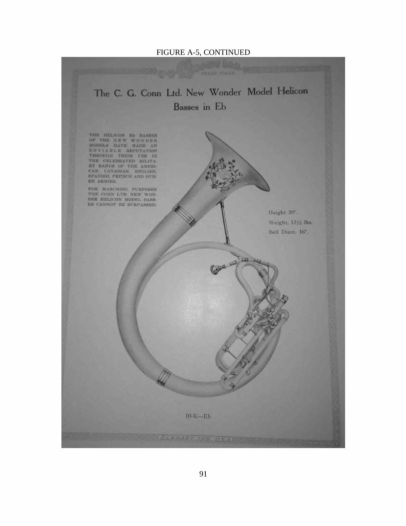
91
FIGURE A-5, CONTINUED

92
FIGURE A-5, CONTINUED

93
FIGURE A-5, CONTINUED

94
FIGURE A-5, CONTINUED

95
FIGURE A-5, CONTINUED

96
FIGURE A-5, CONTINUED

97
FIGURE A-5, CONTINUED

98
FIGURE A-5, CONTINUED

99
FIGURE A-5, CONTINUED

100
FIGURE A-5, CONTINUED

101
FIGURE A-5, CONTINUED

102
FIGURE A-5, CONTINUED

103
FIGURE A-5, CONTINUED

104
FIGURE A-5, CONTINUED

105
FIGURE A-5, CONTINUED

106
FIGURE A-5, CONTINUED

107
FIGURE A-5, CONTINUED

108
FIGURE A-5, CONTINUED

109
FIGURE A-5, CONTINUED

110
FIGURE A-5, CONTINUED

111
FIGURE A-5, CONTINUED

112
FIGURE A-5, CONTINUED

113
FIGURE A-6
Conn General Catalog “B” – Alto Horns and Tenor Horns, November 1924

114
FIGURE A-6, CONTINUED

115
FIGURE A-6, CONTINUED
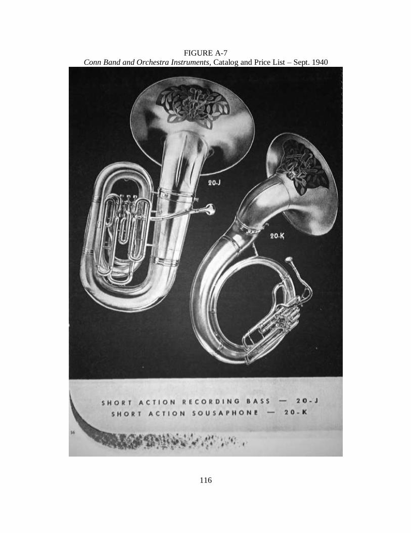
116
FIGURE A-7
Conn Band and Orchestra Instruments, Catalog and Price List – Sept. 1940

117
FIGURE A-7, CONTINUED

118
APPENDIX B
C.G. CONN TUBA-RELATED PATENTS
PATENTS IN CHRONOLOGICAL ORDER

119
FIGURE B-1
PATENT FOR MODIFIED STÖLZEL PISTON VALVES

120
FIGURE B-1, CONTINUED

121
FIGURE B-1, CONTINUED

122
FIGURE B-1, CONTINUED

123
FIGURE B-2
PATENT FOR MODIFIED PÈRINET PISTON VALVES

124
FIGURE B-2, CONTINUED

125
FIGURE B-3:
PATENT FOR AMERICAN MODEL BAND INSTRUMENTS – FRONT-ACTION

126
FIGURE B-3, CONTINUED

127
FIGURE B-3, CONTINUED

128
FIGURE B-4
PATENT FOR WONDER MODEL BAND INSTRUMENTS – TOP-ACTION

129
FIGURE B-4, CONTINUED

130
FIGURE B-4, CONTINUED

131
FIGURE B-4, CONTINUED

132
APPENDIX C
DIAGRAMS OF MEASUREMENT POINTS ON FRONT-ACTION TUBAS

133
FIGURE C-1
FRONT-ACTION/CONN AMERICAN MODEL
Figures C-2 through C-9 (with the exception of Figure A-3) will be drawn from this
reference image.

134
FIGURE C-2
FRONT-ACTION MEASUREMENT POINTS 1 – 3
1. Diameter of interior of mouthpiece receiver
2. Diameter of exterior of mouthpiece receiver
3. Length of lead-pipe from termination of receiver to either valve entry or primary
tuning slide

135
FIGURE C-3
FRONT-ACTION MEASUREMENT POINTS 4 – 12
4. Length of 1
st valve casing
5. Length of 2nd
valve casing
6. Length of 3rd
valve casing
7. Diameter of 1st valve piston
8. Diameter of 2nd
valve piston
9. Diameter of 3rd
valve piston
10. Diameter of 1st valve port
11. Diameter of 2nd
valve port
12. Diameter of 3rd
valve port

136
FIGURE C-4
FRONT-ACTION MEASUREMENT POINTS 13 – 20
13. Length of 1st section of 1
st valve tubing
14. Length of 2nd
section of 1st valve tubing
15. Length of 3rd
section of 1st valve tubing
16. Length of 1st section of 2
nd valve tubing

137
17. Length of 2nd
section of 2nd
valve tubing (located behind the 1st section in this image)
18. Length of 1st section of 3
rd valve tubing
19. Length of 2nd
section of 3rd
valve tubing
20. Length of 3rd
section of 3rd
valve tubing

138
FIGURE C-5
FRONT-ACTION MEASUREMENT POINTS 21 – 23
21. External diameter of 1
st valve tuning slide between ferrules
22. External diameter of 2nd
valve tuning slide between ferrules
23. External diameter of 3rd
valve tuning slide between ferrules
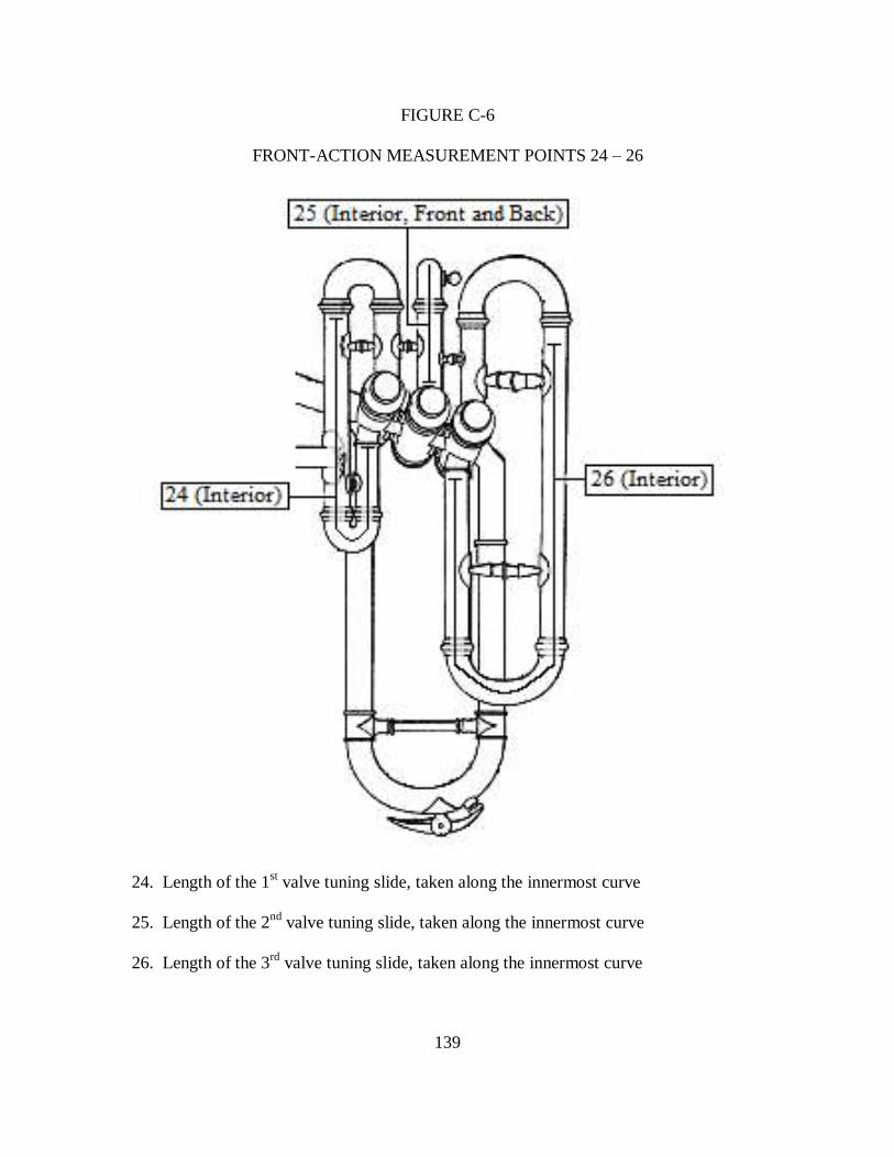
139
FIGURE C-6
FRONT-ACTION MEASUREMENT POINTS 24 – 26
24. Length of the 1st valve tuning slide, taken along the innermost curve
25. Length of the 2nd
valve tuning slide, taken along the innermost curve
26. Length of the 3rd
valve tuning slide, taken along the innermost curve
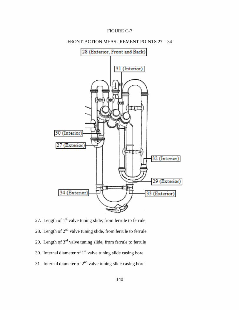
140
FIGURE C-7
FRONT-ACTION MEASUREMENT POINTS 27 – 34
27. Length of 1
st valve tuning slide, from ferrule to ferrule
28. Length of 2nd
valve tuning slide, from ferrule to ferrule
29. Length of 3rd
valve tuning slide, from ferrule to ferrule
30. Internal diameter of 1st valve tuning slide casing bore
31. Internal diameter of 2nd
valve tuning slide casing bore

141
32. Internal diameter of 3rd
valve tuning slide casing bore
33. Exteral diameter of the 1st ferrule of the primary tuning slide
34. External diameter of the 2nd
ferrule of the primary tuning slide

142
FIGURE C-8
FRONT-ACTION MEASUREMENT POINTS 35-39
35. Length of primary tuning slide from ferrule to ferrule
36. Interior diameter of 1st section of primary tuning slide
37. Interior diameter of 2nd
section of primary tuning slide
38. Interior diameter of 1st section of primary tuning slide casing bore
39. Interior diameter of 2nd
section of primary tuning slide casing bore

143
FIGURE C-9
FRONT-ACTION MEASUREMENT POINTS 40 – 47

144
FIGURE C-9, CONTINUED
40. Circumference of 1st section of the 2
nd bough at ferrule
41. Circumference of 2nd
section of the 2nd
bough at ferrule
42. Circumference of 1st section of the primary bough at ferrule
43. Circumference of 2nd
section of the primary bough at ferrule
44. Length of primary bough taken along bough plate from ferrule to ferrule
45. Cirumference of bell at ferrule
46. Length of bell from ferrule to rim
47. Bell diameter

145
APPENDIX D
DIAGRAMS OF MEASUREMENT POINTS ON TOP-ACTION TUBAS

146
FIGURE D-1
TOP-ACTION/CONN WONDER MODEL
Figures D-2 through D-9 (with the exception of Figure D-3) will be drawn from this
reference image.

147
FIGURE D-2
TOP-ACTION MEASUREMENT POINTS 1 – 3
1. Diameter of interior of mouthpiece receiver
2. Diameter of exterior of mouthpiece receiver
3. Length of lead-pipe from termination of receiver to either valve entry or primary
tuning slide

148
FIGURE D-3
TOP-ACTION MEASUREMENT POINTS 4 – 12
4. Length of 1
st valve casing
5. Length of 2nd
valve casing
6. Length of 3rd
valve casing
7. Diameter of 1st valve piston
8. Diameter of 2nd
valve piston
9. Diameter of 3rd
valve piston
10. Diameter of 1st valve port
11. Diameter of 2nd
valve port
12. Diameter of 3rd
valve port

149
FIGURE D-4
TOP-ACTION MEASUREMENT POINTS 13 – 20
13. Length of 1st section of 1
st valve tubing
14. Length of 2nd
section of 1st valve tubing
*15. Length of 3rd
section of 1st valve tubing is not present on top-action Eb tubas
16. Length of 1st section of 2
nd valve tubing
17. Length of 2nd
section of 2nd
valve tubing (located behind the 1st section in this image)
18. Length of 1st section of 3
rd valve tubing

150
19. Length of 2nd
section of 3rd
valve tubing
*20. Length of 3rd
section of 3rd
valve tubing is not present on top-action Eb tubas

151
FIGURE D-5
TOP-ACTION MEASUREMENT POINTS 21 – 23
21. External diameter of 1
st valve tuning slide between ferrules
22. External diameter of 2nd
valve tuning slide between ferrules
23. External diameter of 3rd
valve tuning slide between ferrules

152
FIGURE D-6
TOP-ACTION MEASUREMENT POINTS 24 – 26
24. Length of the 1
st valve tuning slide, taken along the innermost curve
25. Length of the 2nd
valve tuning slide, taken along the innermost curve
26. Length of the 3rd
valve tuning slide, taken along the innermost curve

153
FIGURE D-7
TOP-ACTION MEASUREMENT POINTS 27 – 34
27. Length of 1
st valve tuning slide, from ferrule to ferrule
28. Length of 2nd
valve tuning slide, from ferrule to ferrule
29. Length of 3rd
valve tuning slide, from ferrule to ferrule
30. Internal diameter of 1st valve tuning slide casing bore
31. Internal diameter of 2nd
valve tuning slide casing bore
32. Internal diameter of 3rd
valve tuning slide casing bore
33. Exteral diameter of the 1st ferrule of the primary tuning slide
34. External diameter of the 2nd
ferrule of the primary tuning slide

154
FIGURE D-8
TOP-ACTION MEASUREMENT POINTS 35-39
35. Length of primary tuning slide from ferrule to ferrule
36. Interior diameter of 1st section of primary tuning slide
37. Interior diameter of 2nd
section of primary tuning slide
38. Interior diameter of 1st section of primary tuning slide casing bore
39. Interior diameter of 2nd
section of primary tuning slide casing bore

155
FIGURE D-9
TOP-ACTION MEASUREMENT POINTS 40-47

156
FIGURE D-9, CONTINUED
40. Circumference of 1st section of the 2
nd bough at ferrule
41. Circumference of 2nd
section of the 2nd
bough at ferrule
42. Circumference of 1st section of the primary bough at ferrule
43. Circumference of 2nd
section of the primary bough at ferrule
44. Length of primary bough taken along bough plate from ferrule to ferrule
45. Cirumference of bell at ferrule
46. Length of bell from ferrule to rim
47. Bell diameter

157
APPENDIX E
PHOTOGRAPHS OF PROCEDURES AND INSTRUMENTS

158
FIGURE E-1
BOUGH CIRCUMFERENCE MEASUREMENT

159
FIGURE E-2
BELL DIAMETER MEASUREMENT

160
FIGURE E-3
BELL LENGTH MEASUREMENT

161
FIGURE E-4
FRONT-ACTION VALVE APPARATUS

162
FIGURE E-5
UPPER TUBING OF FRONT-ACTION VALVE APPARATUS

163
FIGURE E-6
TOP-ACTION VALVE APPARATUS

164
FIGURE E-7
EXAMPLE OF BOUGH DAMAGE
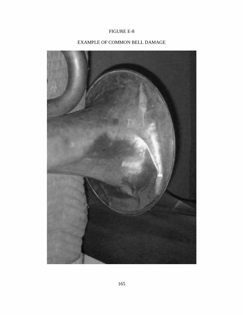
165
FIGURE E-8
EXAMPLE OF COMMON BELL DAMAGE

166
FIGURE E-9
EXAMPLE OF BELL WIDENING (DAMAGE)

167
APPENDIX F
MEASUREMENTS AND FIELD RESEARCH DATA

168
FIGURE F-1
MEASUREMENTS AT 0.001 INCHES
This spreadsheet represents the initial spreadsheet after collecting measurements at an
accuracy of 0.001 inches. Blank cells represent an area that was inaccessible due to
instrument damage.
Serial Number 17793 18616 28941 31856 62905 70393 71782 161839 163855 173734 178831 183987 188071 204222
Date ca. 1890 1890 ca. 1894 ca. 1895 1901 ca. 1901 ca. 1902 1918 ca.1918 ca. 1920 ca. 1921 ca. 1921 1922 ca. 1923
NMM Number 2565 254 4147 106 270 129 120 353 126 348 5965 2637 1344 10018
Model
American
Model Eb
Bass
New
American
Model Eb
Bass
The New
American
Model Eb
Bass
New
American
Model Eb
Bass
New
Wonder
Model Eb
Bass
New
Wonder
Model Eb
Bass
Profession
al Model Eb
Bass
"Giant"
Model
Contra Eb
Bass
"Professio
nal" Eb
Bass
New
Wonder
Model
Standard
Eb Bass
New
Wonder
Model
Standard
Eb Bass
New
Wonder
Model
Monster
Eb Bass
New
Wonder
Model
Monster Eb
Bass
Action Type Front Front Front Front Top Top Front Top Top Top Front Top Front Front
1 Receiver Diameter Int 0.515 0.516 0.531 0.517 0.534 0.468 0.537 0.522 0.565 0.525 0.519 0.526 0.569 0.549
2 Receiver Diameter Ext 0.681 0.685 0.701 0.680 0.686 0.699 0.672 0.705 0.732 0.708 0.704 0.702 0.736 0.740
3 Lead-pipe Length 9.563 9.375 9.250 8.688 8.438 8.875 9.438 10.250 11.750 9.188 9.750 11.063 10.375
4 Piston Casing Height 1 4.113 4.010 4.038 4.191 4.760 4.690 4.125 4.694 3.983 4.095 4.176 4.519 4.595
5 Piston Casing Height 2 4.177 4.123 4.103 4.122 4.687 4.802 4.049 4.727 4.007 4.113 4.161 4.628 4.594
6 Piston Casing Height 3 4.177 4.119 4.071 4.058 4.536 4.792 4.104 4.695 4.139 4.107 4.161 4.628 4.596
7 Piston Diameter 1 0.883 0.894 0.894 0.888 0.886 0.897 0.880 1.046 0.881 0.887 1.048 1.040
8 Piston Diameter 2 0.879 0.887 0.887 0.891 0.888 0.890 0.896 0.880 1.042 0.882 0.889 0.884 1.047 1.039
9 Piston Diameter 3 0.880 0.888 0.885 0.891 0.895 0.879 0.884 0.884 1.048 1.041
10 Port Diameter 1 0.592 0.598 0.613 0.618 0.631 0.563 0.611 0.683 0.605 0.599 0.687 0.688
11 Port Diameter 2 0.610 0.602 0.594 0.619 0.618 0.609 0.586 0.616 0.671 0.606 0.605 0.610 0.683 0.683
12 Port Diameter 3 0.593 0.600 0.632 0.614 0.600 0.611 0.607 0.608 0.688 0.681
13 1 Valve length 1 2.537 1.960 2.072 2.082 6.220 6.246 6.875 7.688 6.625 7.688 2.504 7.250 6.230 6.196
14 1 Valve length 2 6.386 6.378 6.750 6.875 4.420 4.426 3.815 5.015 2.994 5.022 7.188 4.419 3.804 3.798
15 1 Valve length 3 3.309 3.302 3.677 3.820 3.761
16 2 Valve length 1 2.906 2.894 2.885 2.879 0.742 0.784 2.908 1.999 2.292 1.989 3.000 2.183 3.190 3.107
17 2 Valve length 2 2.533 2.539 2.533 2.543 2.864 2.869 2.512 2.380 1.636 2.372 3.373 1.811 2.882 2.874
18 3 Valve length 1 3.159 3.153 3.135 3.270 9.938 9.938 3.286 10.750 9.063 10.625 3.894 13.000 3.688 2.998
19 3 Valve length 2 12.438 12.375 13.250 13.125 13.125 13.063 13.250 13.438 12.813 13.375 13.500 10.250 12.125 12.313
20 3 Valve length 3 8.313 8.250 8.875 8.938 8.938 8.313 7.625 7.625
21 Valve ferrule diameter 1 0.647 0.657 0.659 0.670 0.662 0.669 0.667 0.666 0.742 0.662 0.666 0.668 0.741 0.744
22 Valve ferrule diameter 2 0.653 0.647 0.665 0.671 0.668 0.666 0.671 0.673 0.734 0.676 0.672 0.746 0.742
23 Valve ferrule diameter 3 0.664 0.657 0.662 0.669 0.663 0.666 0.685 0.668 0.747 0.656 0.665 0.670 0.747 0.746
24 Valve slide length 1 9.250 9.563 10.375 10.375 11.438 11.375 2.813 9.375 9.063 11.875 9.875
25 Valve slide length 2 6.500 6.313 6.563 2.625 5.063 4.875 7.188 4.500 6.875 6.813
26 Valve slide length 3 8.750 21.125 11.375 11.688 12.125 11.313 10.813 11.250 10.375 11.438
27 Short V. slide length 1 1.063 1.375 1.063 1.250 0.938 1.063 1.188 1.313 1.250 1.250 1.250 1.250
28 Short V. slide length 2 0.688 0.750 0.500 0.875 0.250 0.500 0.438 0.563 0.813 0.438 0.563 0.500
29 Short V. slide length 3 1.375 2.250 1.188 1.500 1.813 1.188 2.188 1.938 1.313 2.063 2.250 2.188
30 1 Valve bore 0.594 0.639 0.652 0.652 0.658 0.639 0.658 0.736 0.659 0.658 0.736 0.743
31 2 Valve bore 0.614 0.636 0.647 0.658 0.641 0.662 0.732 0.667 0.650 0.741 0.745
32 3 Valve bore 0.640 0.660 0.649 0.657 0.655 0.661 0.730 0.663 0.661 0.736 0.740
33 PTS ferrule diameter 1 0.641 0.665 0.655 0.706 0.701 0.618 0.639 0.629 0.625 0.708 0.705
34 PTS ferrule diameter 2 0.676 0.686 0.692 0.700 0.726 0.725 0.677 0.669 0.661 0.668 0.744 0.740
35 PTS length (fer to fer) 4.313 4.375 4.000 4.063 4.750 5.000 1.188 1.500 1.188 1.000 1.563 1.563
36 PTS diameter entrance 0.597 0.610 0.603 0.649 0.643 0.557 0.592 0.580 0.653 0.635
37 PTS diameter exit 0.635 0.631 0.643 0.693 0.686 0.613 0.619 0.608 0.692 0.687
38 PTS casing diameter ent 0.641 0.659 0.649 0.700 0.694 0.660 0.688 0.616 0.624 0.627 0.688 0.690
39 PTS casing diameter exit 0.677 0.697 0.684 0.723 0.731 0.688 0.740 0.656 0.660 0.663 0.740 0.747
40 2nd bow circumference 1 4.750 4.875 4.625 4.375 4.813 4.688 4.438 5.250 5.688 5.250 4.563 5.750 5.750 5.625
41 2nd bow circumference 2 8.500 8.500 8.563 8.250 8.688 8.313 8.438 9.500 11.125 9.563 8.250 8.375 11.000 11.000
42 Prime bow circumference 1 8.438 8.563 8.500 8.375 8.563 8.500 8.500 9.563 11.250 9.563 8.375 8.250 11.375 11.250
43 Prime bow circumference 2 10.563 10.813 10.813 10.250 10.250 10.250 10.250 12.188 14.938 12.125 10.313 10.125 14.938 14.938
44 Primary bow length 21.563 21.250 21.875 21.438 21.625 21.250 21.500 23.250 26.875 23.688 21.250 21.500 27.063 26.813
45 Bell circum at ferrule 11.125 11.000 11.125 10.625 10.750 10.625 10.625 12.750 15.500 12.625 10.625 10.625 15.375 15.563
46 Bell section length 23.188 22.875 23.250 24.750 25.125 24.875 25.375 27.250 29.000 27.375 25.500 26.000 29.250 28.875
47 Bell diameter 14.375 14.188 14.125 14.063 14.125 14.125 14.250 18.000 20.125 18.188 16.000 16.000 20.000 20.000
Measu
remen
t Nu
mb
er

169
FIGURE F-2
MEASUREMENTS AT 0.01 INCHES
This spreadsheet represents the initial spreadsheet after collecting measurements at an
accuracy of 0.01 inches.
Serial Number 17793 18616 28941 31856 62905 70393 71782 161839 163855 173734 178831 183987 188071 204222
Date ca. 1890 1890 ca. 1894 ca. 1895 1901 ca. 1901 ca. 1902 1918 ca.1918 ca. 1920 ca. 1921 ca. 1921 1922 ca. 1923
NMM Number 2565 254 4147 106 270 129 120 353 126 348 5965 2637 1344 10018
Model
American
Model Eb
Bass
New
American
Model Eb
Bass
The New
American
Model Eb
Bass
New
American
Model Eb
Bass
New
Wonder
Model Eb
Bass
New
Wonder
Model Eb
Bass
Professio
nal Model
Eb Bass
"Giant"
Model
Contra Eb
Bass
"Professio
nal" Eb
Bass
New
Wonder
Model
Standard Eb
Bass
New
Wonder
Model
Standard Eb
Bass
New
Wonder
Model
Monster Eb
Bass
New
Wonder
Model
Monster Eb
Bass
Action Type Front Front Front Front Top Top Front Top Top Top Front Top Front Front
1 Receiver Diameter Int 0.52 0.52 0.53 0.52 0.53 0.47 0.54 0.52 0.57 0.53 0.52 0.53 0.57 0.55
2 Receiver Diameter Ext 0.68 0.69 0.70 0.68 0.69 0.70 0.67 0.71 0.73 0.71 0.70 0.70 0.74 0.74
3 Lead-pipe Length 9.56 9.38 9.25 8.69 8.44 8.88 9.44 10.25 11.75 9.19 9.75 11.06 10.38
4 Piston Casing Height 1 4.11 4.01 4.04 4.19 4.76 4.69 4.13 4.69 3.98 4.10 4.18 4.52 4.60
5 Piston Casing Height 2 4.18 4.12 4.10 4.12 4.69 4.80 4.05 4.73 4.01 4.11 4.16 4.63 4.59
6 Piston Casing Height 3 4.18 4.12 4.07 4.06 4.54 4.79 4.10 4.70 4.14 4.11 4.16 4.63 4.60
7 Piston Diameter 1 0.88 0.89 0.89 0.89 0.89 0.90 0.88 1.05 0.88 0.89 1.05 1.04
8 Piston Diameter 2 0.88 0.89 0.89 0.89 0.89 0.89 0.90 0.88 1.04 0.88 0.89 0.88 1.05 1.04
9 Piston Diameter 3 0.88 0.89 0.89 0.89 0.90 0.88 0.88 0.88 1.05 1.04
10 Port Diameter 1 0.59 0.60 0.61 0.62 0.63 0.56 0.61 0.68 0.61 0.60 0.69 0.69
11 Port Diameter 2 0.61 0.60 0.59 0.62 0.62 0.61 0.59 0.62 0.67 0.61 0.61 0.61 0.68 0.68
12 Port Diameter 3 0.59 0.60 0.63 0.61 0.60 0.61 0.61 0.61 0.69 0.68
13 1 Valve length 1 2.54 1.96 2.07 2.08 6.22 6.25 6.88 7.69 6.63 7.69 2.50 7.25 6.23 6.20
14 1 Valve length 2 6.39 6.38 6.75 6.88 4.42 4.43 3.82 5.02 2.99 5.02 7.19 4.42 3.80 3.80
15 1 Valve length 3 3.31 3.30 3.68 3.82 3.76
16 2 Valve length 1 2.91 2.89 2.89 2.88 0.74 0.78 2.91 2.00 2.29 1.99 3.00 2.18 3.19 3.11
17 2 Valve length 2 2.53 2.54 2.53 2.54 2.86 2.87 2.51 2.38 1.64 2.37 3.37 1.81 2.88 2.87
18 3 Valve length 1 3.16 3.15 3.14 3.27 9.94 9.94 3.29 10.75 9.06 10.63 3.89 13.00 3.69 3.00
19 3 Valve length 2 12.44 12.38 13.25 13.13 13.13 13.06 13.25 13.44 12.81 13.38 13.50 10.25 12.13 12.31
20 3 Valve length 3 8.31 8.25 8.88 8.94 8.94 8.31 7.63 7.63
21 Valve ferrule diameter 1 0.65 0.66 0.66 0.67 0.66 0.67 0.67 0.67 0.74 0.66 0.67 0.67 0.74 0.74
22 Valve ferrule diameter 2 0.65 0.65 0.67 0.67 0.67 0.67 0.67 0.67 0.73 0.68 0.67 0.75 0.74
23 Valve ferrule diameter 3 0.66 0.66 0.66 0.67 0.66 0.67 0.69 0.67 0.75 0.66 0.67 0.67 0.75 0.75
24 Valve slide length 1 9.25 9.56 10.38 10.38 11.44 11.38 2.81 9.38 9.06 11.88 9.88
25 Valve slide length 2 6.50 6.31 6.56 2.63 5.06 4.88 7.19 4.50 6.88 6.81
26 Valve slide length 3 8.75 21.13 11.38 11.69 12.13 11.31 10.81 11.25 10.38 11.44
27 Short V. slide length 1 1.06 1.38 1.06 1.25 0.94 1.06 1.19 1.31 1.25 1.25 1.25 1.25
28 Short V. slide length 2 0.69 0.75 0.50 0.88 0.25 0.50 0.44 0.56 0.81 0.44 0.56 0.50
29 Short V. slide length 3 1.38 2.25 1.19 1.50 1.81 1.19 2.19 1.94 1.31 2.06 2.25 2.19
30 1 Valve bore 0.59 0.64 0.65 0.65 0.66 0.64 0.66 0.74 0.66 0.66 0.74 0.74
31 2 Valve bore 0.61 0.64 0.65 0.66 0.64 0.66 0.73 0.67 0.65 0.74 0.75
32 3 Valve bore 0.64 0.66 0.65 0.66 0.66 0.66 0.73 0.66 0.66 0.74 0.74
33 PTS ferrule diameter 1 0.64 0.67 0.66 0.71 0.70 0.62 0.64 0.63 0.63 0.71 0.71
34 PTS ferrule diameter 2 0.68 0.69 0.69 0.70 0.73 0.73 0.68 0.67 0.66 0.67 0.74 0.74
35 PTS length (fer to fer) 4.31 4.38 4.00 4.06 4.75 5.00 1.19 1.50 1.19 1.00 1.56 1.56
36 PTS diameter entrance 0.60 0.61 0.60 0.65 0.64 0.56 0.59 0.58 0.65 0.64
37 PTS diameter exit 0.64 0.63 0.64 0.69 0.69 0.61 0.62 0.61 0.69 0.69
38 PTS casing diameter ent 0.64 0.66 0.65 0.70 0.69 0.66 0.69 0.62 0.62 0.63 0.69 0.69
39 PTS casing diameter exit 0.68 0.70 0.68 0.72 0.73 0.69 0.74 0.66 0.66 0.66 0.74 0.75
40 2nd bow circumference 1 4.75 4.88 4.63 4.38 4.81 4.69 4.44 5.25 5.69 5.25 4.56 5.75 5.75 5.63
41 2nd bow circumference 2 8.50 8.50 8.56 8.25 8.69 8.31 8.44 9.50 11.13 9.56 8.25 8.38 11.00 11.00
42 Prime bow circumference 1 8.44 8.56 8.50 8.38 8.56 8.50 8.50 9.56 11.25 9.56 8.38 8.25 11.38 11.25
43 Prime bow circumference 2 10.56 10.81 10.81 10.25 10.25 10.25 10.25 12.19 14.94 12.13 10.31 10.13 14.94 14.94
44 Primary bow length 21.56 21.25 21.88 21.44 21.63 21.25 21.50 23.25 26.88 23.69 21.25 21.50 27.06 26.81
45 Bell circum at ferrule 11.13 11.00 11.13 10.63 10.75 10.63 10.63 12.75 15.50 12.63 10.63 10.63 15.38 15.56
46 Bell section length 23.19 22.88 23.25 24.75 25.13 24.88 25.38 27.25 29.00 27.38 25.50 26.00 29.25 28.88
47 Bell diameter 14.38 14.19 14.13 14.06 14.13 14.13 14.25 18.00 20.13 18.19 16.00 16.00 20.00 20.00
Measu
remen
t Nu
mb
er

170
FIGURE F-3
EXACT MATCHES AT 0.001 INCHES
This spreadsheet represents the identical matches found at an accuracy of 0.001 inches.
These matches are organized by row, and the different shades indicate which
measurements match. The percentage of identical matches found at this level of accuracy
is 19.55%.
Serial Number 17793 18616 28941 31856 62905 70393 71782 161839 163855 173734 178831 183987 2E+05 204222
Date ca. 1890 1890 ca. 1894 ca. 1895 1901 ca. 1901 ca. 1902 1918 ca.1918 ca. 1920 ca. 1921 ca. 1921 1922 ca. 1923
NMM Number 2565 254 4147 106 270 129 120 353 126 348 5965 2637 1344 10018
Model
American
Model Eb
Bass
New
American
Model Eb
Bass
The New
American
Model Eb
Bass
New
American
Model Eb
Bass
New
Wonder
Model Eb
Bass
New
Wonder
Model Eb
Bass
Professio
nal
Model Eb
Bass
"Giant"
Model
Contra Eb
Bass
"Professio
nal" Eb
Bass
New
Wonder
Model
Standard
Eb Bass
New
Wonder
Model
Standard
Eb Bass
New
Wonder
Model
Monster
Eb Bass
New
Wonder
Model
Monster Eb
Bass
Action Type Front Front Front Front Top Top Front Top Top Top Front Top Front Front
1 Receiver Diameter Int 0.515 0.516 0.531 0.517 0.534 0.468 0.537 0.522 0.565 0.525 0.519 0.526 0.569 0.549
2 Receiver Diameter Ext 0.681 0.685 0.701 0.680 0.686 0.699 0.672 0.705 0.732 0.708 0.704 0.702 0.736 0.740
3 Lead-pipe Length 9.563 9.375 9.250 8.688 8.438 8.875 9.438 10.250 11.750 9.188 9.750 11.063 10.375
4 Piston Casing Height 1 4.113 4.010 4.038 4.191 4.760 4.690 4.125 4.694 3.983 4.095 4.176 4.519 4.595
5 Piston Casing Height 2 4.177 4.123 4.103 4.122 4.687 4.802 4.049 4.727 4.007 4.113 4.161 4.628 4.594
6 Piston Casing Height 3 4.177 4.119 4.071 4.058 4.536 4.792 4.104 4.695 4.139 4.107 4.161 4.628 4.596
7 Piston Diameter 1 0.883 0.894 0.894 0.888 0.886 0.897 0.880 1.046 0.881 0.887 1.048 1.040
8 Piston Diameter 2 0.879 0.887 0.887 0.891 0.888 0.890 0.896 0.880 1.042 0.882 0.889 0.884 1.047 1.039
9 Piston Diameter 3 0.880 0.888 0.885 0.891 0.895 0.879 0.884 0.884 1.048 1.041
10 Port Diameter 1 0.592 0.598 0.613 0.618 0.631 0.563 0.611 0.683 0.605 0.599 0.687 0.688
11 Port Diameter 2 0.610 0.602 0.594 0.619 0.618 0.609 0.586 0.616 0.671 0.606 0.605 0.610 0.683 0.683
12 Port Diameter 3 0.593 0.600 0.632 0.614 0.600 0.611 0.607 0.608 0.688 0.681
13 1 Valve length 1 2.537 1.960 2.072 2.082 6.220 6.246 6.875 7.688 6.625 7.688 2.504 7.250 6.230 6.196
14 1 Valve length 2 6.386 6.378 6.750 6.875 4.420 4.426 3.815 5.015 2.994 5.022 7.188 4.419 3.804 3.798
15 1 Valve length 3 3.309 3.302 3.677 3.820 3.761
16 2 Valve length 1 2.906 2.894 2.885 2.879 0.742 0.784 2.908 1.999 2.292 1.989 3.000 2.183 3.190 3.107
17 2 Valve length 2 2.533 2.539 2.533 2.543 2.864 2.869 2.512 2.380 1.636 2.372 3.373 1.811 2.882 2.874
18 3 Valve length 1 3.159 3.153 3.135 3.270 9.938 9.938 3.286 10.750 9.063 10.625 3.894 13.000 3.688 2.998
19 3 Valve length 2 12.438 12.375 13.250 13.125 13.125 13.063 13.250 13.438 12.813 13.375 13.500 10.250 12.125 12.313
20 3 Valve length 3 8.313 8.250 8.875 8.938 8.938 8.313 7.625 7.625
21 Valve ferrule diameter 1 0.647 0.657 0.659 0.670 0.662 0.669 0.667 0.666 0.742 0.662 0.666 0.668 0.741 0.744
22 Valve ferrule diameter 2 0.653 0.647 0.665 0.671 0.668 0.666 0.671 0.673 0.734 0.676 0.672 0.746 0.742
23 Valve ferrule diameter 3 0.664 0.657 0.662 0.669 0.663 0.666 0.685 0.668 0.747 0.656 0.665 0.670 0.747 0.746
24 Valve slide length 1 9.250 9.563 10.375 10.375 11.438 11.375 2.813 9.375 9.063 11.875 9.875
25 Valve slide length 2 6.500 6.313 6.563 2.625 5.063 4.875 7.188 4.500 6.875 6.813
26 Valve slide length 3 8.750 21.125 11.375 11.688 12.125 11.313 10.813 11.250 10.375 11.438
27 Short V. slide length 1 1.063 1.375 1.063 1.250 0.938 1.063 1.188 1.313 1.250 1.250 1.250 1.250
28 Short V. slide length 2 0.688 0.750 0.500 0.875 0.250 0.500 0.438 0.563 0.813 0.438 0.563 0.500
29 Short V. slide length 3 1.375 2.250 1.188 1.500 1.813 1.188 2.188 1.938 1.313 2.063 2.250 2.188
30 1 Valve bore 0.594 0.639 0.652 0.652 0.658 0.639 0.658 0.736 0.659 0.658 0.736 0.743
31 2 Valve bore 0.614 0.636 0.647 0.658 0.641 0.662 0.732 0.667 0.650 0.741 0.745
32 3 Valve bore 0.640 0.660 0.649 0.657 0.655 0.661 0.730 0.663 0.661 0.736 0.740
33 PTS ferrule diameter 1 0.641 0.665 0.655 0.706 0.701 0.618 0.639 0.629 0.625 0.708 0.705
34 PTS ferrule diameter 2 0.676 0.686 0.692 0.700 0.726 0.725 0.677 0.669 0.661 0.668 0.744 0.740
35 PTS length (fer to fer) 4.313 4.375 4.000 4.063 4.750 5.000 1.188 1.500 1.188 1.000 1.563 1.563
36 PTS diameter entrance 0.597 0.610 0.603 0.649 0.643 0.557 0.592 0.580 0.653 0.635
37 PTS diameter exit 0.635 0.631 0.643 0.693 0.686 0.613 0.619 0.608 0.692 0.687
38 PTS casing diameter ent 0.641 0.659 0.649 0.700 0.694 0.660 0.688 0.616 0.624 0.627 0.688 0.690
39 PTS casing diameter exit 0.677 0.697 0.684 0.723 0.731 0.688 0.740 0.656 0.660 0.663 0.740 0.747
40 2nd bow circumference 1 4.750 4.875 4.625 4.375 4.813 4.688 4.438 5.250 5.688 5.250 4.563 5.750 5.750 5.625
41 2nd bow circumference 2 8.500 8.500 8.563 8.250 8.688 8.313 8.438 9.500 11.125 9.563 8.250 8.375 11.000 11.000
42 Prime bow circumference 1 8.438 8.563 8.500 8.375 8.563 8.500 8.500 9.563 11.250 9.563 8.375 8.250 11.375 11.250
43 Prime bow circumference 2 10.563 10.813 10.813 10.250 10.250 10.250 10.250 12.188 14.938 12.125 10.313 10.125 14.938 14.938
44 Primary bow length 21.563 21.250 21.875 21.438 21.625 21.250 21.500 23.250 26.875 23.688 21.250 21.500 27.063 26.813
45 Bell circum at ferrule 11.125 11.000 11.125 10.625 10.750 10.625 10.625 12.750 15.500 12.625 10.625 10.625 15.375 15.563
46 Bell section length 23.188 22.875 23.250 24.750 25.125 24.875 25.375 27.250 29.000 27.375 25.500 26.000 29.250 28.875
47 Bell diameter 14.375 14.188 14.125 14.063 14.125 14.125 14.250 18.000 20.125 18.188 16.000 16.000 20.000 20.000
Measu
remen
t Nu
mb
er
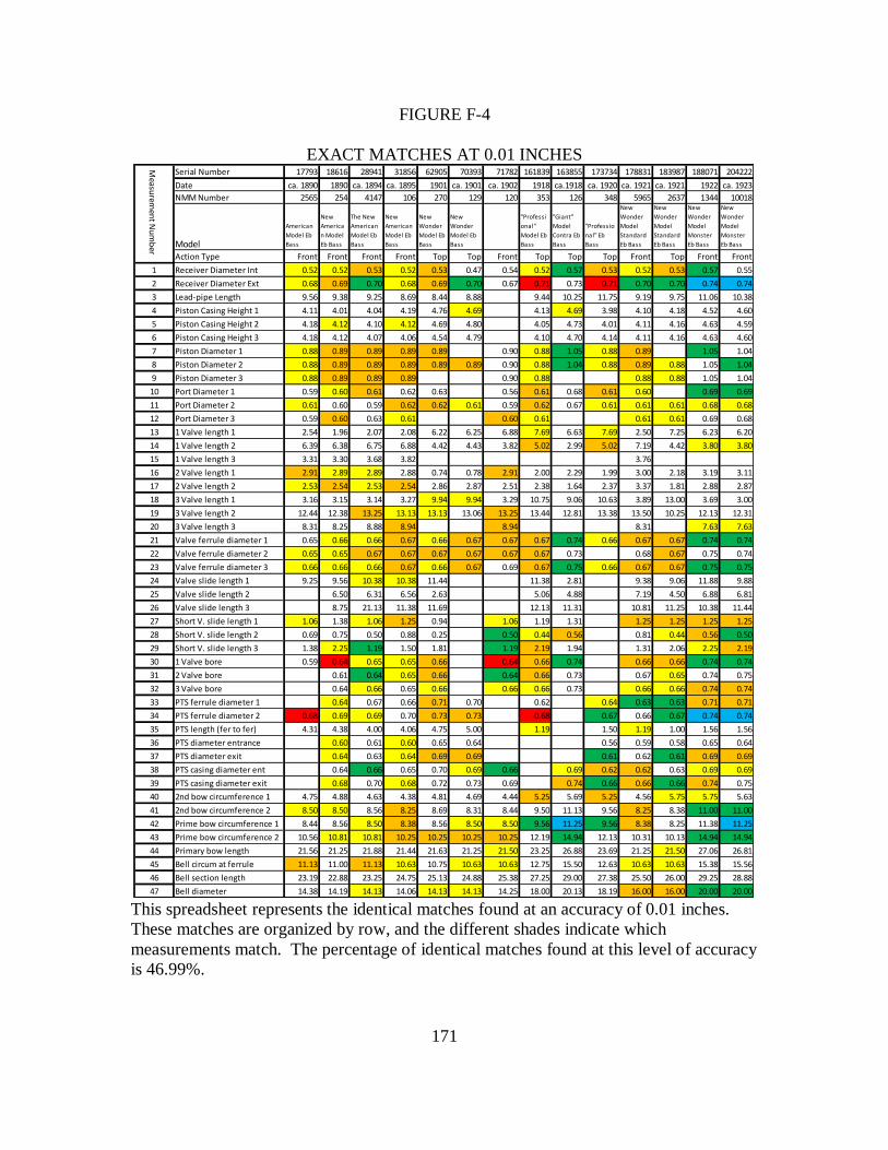
171
FIGURE F-4
EXACT MATCHES AT 0.01 INCHES
This spreadsheet represents the identical matches found at an accuracy of 0.01 inches.
These matches are organized by row, and the different shades indicate which
measurements match. The percentage of identical matches found at this level of accuracy
is 46.99%.
Serial Number 17793 18616 28941 31856 62905 70393 71782 161839 163855 173734 178831 183987 188071 204222
Date ca. 1890 1890 ca. 1894 ca. 1895 1901 ca. 1901 ca. 1902 1918 ca.1918 ca. 1920 ca. 1921 ca. 1921 1922 ca. 1923
NMM Number 2565 254 4147 106 270 129 120 353 126 348 5965 2637 1344 10018
Model
American
Model Eb
Bass
New
America
n Model
Eb Bass
The New
American
Model Eb
Bass
New
American
Model Eb
Bass
New
Wonder
Model Eb
Bass
New
Wonder
Model Eb
Bass
"Professi
onal"
Model Eb
Bass
"Giant"
Model
Contra Eb
Bass
"Professio
nal" Eb
Bass
New
Wonder
Model
Standard
Eb Bass
New
Wonder
Model
Standard
Eb Bass
New
Wonder
Model
Monster
Eb Bass
New
Wonder
Model
Monster
Eb Bass
Action Type Front Front Front Front Top Top Front Top Top Top Front Top Front Front
1 Receiver Diameter Int 0.52 0.52 0.53 0.52 0.53 0.47 0.54 0.52 0.57 0.53 0.52 0.53 0.57 0.55
2 Receiver Diameter Ext 0.68 0.69 0.70 0.68 0.69 0.70 0.67 0.71 0.73 0.71 0.70 0.70 0.74 0.74
3 Lead-pipe Length 9.56 9.38 9.25 8.69 8.44 8.88 9.44 10.25 11.75 9.19 9.75 11.06 10.38
4 Piston Casing Height 1 4.11 4.01 4.04 4.19 4.76 4.69 4.13 4.69 3.98 4.10 4.18 4.52 4.60
5 Piston Casing Height 2 4.18 4.12 4.10 4.12 4.69 4.80 4.05 4.73 4.01 4.11 4.16 4.63 4.59
6 Piston Casing Height 3 4.18 4.12 4.07 4.06 4.54 4.79 4.10 4.70 4.14 4.11 4.16 4.63 4.60
7 Piston Diameter 1 0.88 0.89 0.89 0.89 0.89 0.90 0.88 1.05 0.88 0.89 1.05 1.04
8 Piston Diameter 2 0.88 0.89 0.89 0.89 0.89 0.89 0.90 0.88 1.04 0.88 0.89 0.88 1.05 1.04
9 Piston Diameter 3 0.88 0.89 0.89 0.89 0.90 0.88 0.88 0.88 1.05 1.04
10 Port Diameter 1 0.59 0.60 0.61 0.62 0.63 0.56 0.61 0.68 0.61 0.60 0.69 0.69
11 Port Diameter 2 0.61 0.60 0.59 0.62 0.62 0.61 0.59 0.62 0.67 0.61 0.61 0.61 0.68 0.68
12 Port Diameter 3 0.59 0.60 0.63 0.61 0.60 0.61 0.61 0.61 0.69 0.68
13 1 Valve length 1 2.54 1.96 2.07 2.08 6.22 6.25 6.88 7.69 6.63 7.69 2.50 7.25 6.23 6.20
14 1 Valve length 2 6.39 6.38 6.75 6.88 4.42 4.43 3.82 5.02 2.99 5.02 7.19 4.42 3.80 3.80
15 1 Valve length 3 3.31 3.30 3.68 3.82 3.76
16 2 Valve length 1 2.91 2.89 2.89 2.88 0.74 0.78 2.91 2.00 2.29 1.99 3.00 2.18 3.19 3.11
17 2 Valve length 2 2.53 2.54 2.53 2.54 2.86 2.87 2.51 2.38 1.64 2.37 3.37 1.81 2.88 2.87
18 3 Valve length 1 3.16 3.15 3.14 3.27 9.94 9.94 3.29 10.75 9.06 10.63 3.89 13.00 3.69 3.00
19 3 Valve length 2 12.44 12.38 13.25 13.13 13.13 13.06 13.25 13.44 12.81 13.38 13.50 10.25 12.13 12.31
20 3 Valve length 3 8.31 8.25 8.88 8.94 8.94 8.31 7.63 7.63
21 Valve ferrule diameter 1 0.65 0.66 0.66 0.67 0.66 0.67 0.67 0.67 0.74 0.66 0.67 0.67 0.74 0.74
22 Valve ferrule diameter 2 0.65 0.65 0.67 0.67 0.67 0.67 0.67 0.67 0.73 0.68 0.67 0.75 0.74
23 Valve ferrule diameter 3 0.66 0.66 0.66 0.67 0.66 0.67 0.69 0.67 0.75 0.66 0.67 0.67 0.75 0.75
24 Valve slide length 1 9.25 9.56 10.38 10.38 11.44 11.38 2.81 9.38 9.06 11.88 9.88
25 Valve slide length 2 6.50 6.31 6.56 2.63 5.06 4.88 7.19 4.50 6.88 6.81
26 Valve slide length 3 8.75 21.13 11.38 11.69 12.13 11.31 10.81 11.25 10.38 11.44
27 Short V. slide length 1 1.06 1.38 1.06 1.25 0.94 1.06 1.19 1.31 1.25 1.25 1.25 1.25
28 Short V. slide length 2 0.69 0.75 0.50 0.88 0.25 0.50 0.44 0.56 0.81 0.44 0.56 0.50
29 Short V. slide length 3 1.38 2.25 1.19 1.50 1.81 1.19 2.19 1.94 1.31 2.06 2.25 2.19
30 1 Valve bore 0.59 0.64 0.65 0.65 0.66 0.64 0.66 0.74 0.66 0.66 0.74 0.74
31 2 Valve bore 0.61 0.64 0.65 0.66 0.64 0.66 0.73 0.67 0.65 0.74 0.75
32 3 Valve bore 0.64 0.66 0.65 0.66 0.66 0.66 0.73 0.66 0.66 0.74 0.74
33 PTS ferrule diameter 1 0.64 0.67 0.66 0.71 0.70 0.62 0.64 0.63 0.63 0.71 0.71
34 PTS ferrule diameter 2 0.68 0.69 0.69 0.70 0.73 0.73 0.68 0.67 0.66 0.67 0.74 0.74
35 PTS length (fer to fer) 4.31 4.38 4.00 4.06 4.75 5.00 1.19 1.50 1.19 1.00 1.56 1.56
36 PTS diameter entrance 0.60 0.61 0.60 0.65 0.64 0.56 0.59 0.58 0.65 0.64
37 PTS diameter exit 0.64 0.63 0.64 0.69 0.69 0.61 0.62 0.61 0.69 0.69
38 PTS casing diameter ent 0.64 0.66 0.65 0.70 0.69 0.66 0.69 0.62 0.62 0.63 0.69 0.69
39 PTS casing diameter exit 0.68 0.70 0.68 0.72 0.73 0.69 0.74 0.66 0.66 0.66 0.74 0.75
40 2nd bow circumference 1 4.75 4.88 4.63 4.38 4.81 4.69 4.44 5.25 5.69 5.25 4.56 5.75 5.75 5.63
41 2nd bow circumference 2 8.50 8.50 8.56 8.25 8.69 8.31 8.44 9.50 11.13 9.56 8.25 8.38 11.00 11.00
42 Prime bow circumference 1 8.44 8.56 8.50 8.38 8.56 8.50 8.50 9.56 11.25 9.56 8.38 8.25 11.38 11.25
43 Prime bow circumference 2 10.56 10.81 10.81 10.25 10.25 10.25 10.25 12.19 14.94 12.13 10.31 10.13 14.94 14.94
44 Primary bow length 21.56 21.25 21.88 21.44 21.63 21.25 21.50 23.25 26.88 23.69 21.25 21.50 27.06 26.81
45 Bell circum at ferrule 11.13 11.00 11.13 10.63 10.75 10.63 10.63 12.75 15.50 12.63 10.63 10.63 15.38 15.56
46 Bell section length 23.19 22.88 23.25 24.75 25.13 24.88 25.38 27.25 29.00 27.38 25.50 26.00 29.25 28.88
47 Bell diameter 14.38 14.19 14.13 14.06 14.13 14.13 14.25 18.00 20.13 18.19 16.00 16.00 20.00 20.00
Measu
remen
t Nu
mb
er

172
FIGURE F-5
DEFINITIONS OF ABBREVIATIONS
1. Receiver Diameter Int – Diameter of the interior of the mouthpiece receiver
2. Receiver Diameter Ext – Diameter of the exterior of the mouthpiece receiver
3. Lead-pipe Length - Length of lead-pipe from the termination of the mouthpiece
receiver to either the valve entry or the primary tuning slide
4. Piston Casing Height 1 – Length/Height of the 1st valve casing
5. Piston Casing Height 2 – Length/Height of the 2nd
valve casing
6. Piston Casing Height 3 – Length/Height of the 3rd
valve casing
7. Piston Diameter 1 – Diameter of the 1st valve piston
8. Piston Diameter 2 – Diameter of the 2nd
valve piston
9. Piston Diameter 3 – Diameter of the 3rd
valve piston
10. Port Diameter 1 – Diameter of the 1st valve port
11. Port Diameter 2 – Diameter of the 2nd
valve port
12. Port Diameter 3 – Diameter of the 3rd
valve port
13. 1 Valve length 1 – Length of the 1st section of the 1
st valve tubing
14. 1 Valve length 2 – Length of the 2nd
section of the 1st valve tubing
15. 1 Valve length 3 – Length of the 3rd
section of the 1st valve tubing
16. 2 Valve length 1 – Length of the 1st section of the 2
nd valve tubing
17. 2 Valve length 2 – Length of the 2nd
section of the 2nd
valve tubing
18. 3 Valve length 1 – Length of the 1st section of the 3
rd valve tubing
19. 3 Valve length 2 – Length of the 2nd
section of the 3rd
valve tubing

173
20. 3 Valve length 3 – Length of the 3rd
section of the 3rd
valve tubing (present on front-
action Eb tubas but is not present on top-action Eb tubas)
21. Valve ferrule diameter 1 – External diameter of the 1st valve tuning slide between the
ferrules
22. Valve ferrule diameter 2 – External diameter of the 2nd
valve tuning slide between the
ferrules
23. Valve ferrule diameter 3 – External diameter of the 3rd
valve tuning slide between the
ferrules
24. Valve slide length 1 – Length of the 1st valve tuning slide, taken along the innermost
curve of the entire slide
25. Valve slide length 2 – Length of the 2nd
valve tuning slide, taken along the innermost
curve of the entire slide
26. Valve slide length 3 – Length of the 3rd
valve tuning slide, taken along the innermost
curve of the entire slide
27. Short V. slide length 1 – Length of the 1st valve tuning slide, from ferrule to ferrule
along the innermost curve
28. Short V. slide length 2 – Length of the 2nd
valve tuning slide, from ferrule to ferrule
along the innermost curve
29. Short V. slide length 3 – Length of the 3rd
valve tuning slide, from ferrule to ferrule
along the innermost curve
30. 1 Valve bore – Internal diameter of the 1st valve tuning slide casing’s bore

174
31. 2 Valve bore – Internal diameter of the 2nd
valve tuning slide casing’s bore
32. 3 Valve bore – Internal diameter of the 3rd
valve tuning slide casing’s bore
33. PTS ferrule diameter 1 – Exteral diameter of the 1st ferrule of the primary tuning slide
34. PTS ferrule diameter 2 – External diameter of the 2nd
ferrule of the primary tuning
slide
35. PTS length (fer to fer) – Length of the primary tuning slide from ferrule to ferrule
36. PTS diameter entrance – Interior diameter of the 1st section of the primary tuning
slide
37. PTS diameter exit – Interior diameter of the 2nd
section of the primary tuning slide
38. PTS casing diameter ent – Interior diameter of the 1st section of the primary tuning
slide casing’s bore
39. PTS casing diameter exit – Interior diameter of the 2nd
section of the primary tuning
slide casing’s bore
40. 2nd
bow cirumference 1 – Circumference of the 1st section of the 2
nd bough at its
ferrule
41. 2nd
bow circumference 2 – Circumference of the 2nd
section of the 2nd
bough at its
ferrule
42. Prime bow circumference 1 – Circumference of the 1st section of the primary bough
at its ferrule
43. Prime bow circumference 2 – Circumference of the 2nd
section of the primary bough
at its ferrule

175
44. Primary bow length – Length of the primary bough taken along the bough plate from
ferrule to ferrule
45. Bell circum at ferrule – Cirumference of the bell at its ferrule
46. Bell section length – Length of the bell section from ferrule to rim
47. Bell diameter – The bell diameter across the rim

176
APPENDIX G
SUPPLEMENTAL IMAGES

177
FIGURE G-1
AUTHOR’S CONCEPT SKETCH OF INTERCHANGEABLE STRUCTURES
MIRRORED AT BELL

178
FIGURE G-2
INNER WORKINGS OF THE CONN WONDER MODEL VALVE APPARATUS AS
SEEN FROM THE PLAYER’S PERSPECTIVE

179
APPENDIX H
PERMISSION LETTERS

180
FIGURE H-1
PERMISSION TO USE PHOTOGRAPHS OF INSTRUMENTS AND
MEASUREMENTS
from: Clint Spell <[email protected]>
to: David Earll <[email protected]>
date: Wed, Aug 20, 2014 at 6:56 PM
subject:
Re: Use of Photographs from the National Music Museum Research in Doctoral
Research Project
Dear Dave,
I do certainly grant you permission to use the photographs. Best of luck with your
research! Let me know if there's anything else that I can do.
Sincerely,
Clint Spell
On Mon, Aug 18, 2014 at 1:54 PM, David Earll <[email protected]> wrote:
Dear Clint Spell,
I am writing you in regards to our previous discussion about using several photographs
from our time working together at the National Music Museum in my doctoral research
project. In particular, I would like to include several photographs that you took of me
taking measurements of C.G. Conn tubas using my digital camera while conducing my
on-site research at the National Music Museum.
May I have your permission to use these photographs of my measurement procedures for
my doctoral research project? I have included a copy of each of the images that will be
used in my document.
Thank you for your time and consideration.
Sincerely,
David M. Earll

181
FIGURE H-2
PERMISSION TO USE IMAGES FROM THE KEN DROBNAK’S ARTICLE
from: Drobnak, Kenneth <[email protected]>
to: David M Earll <[email protected]>
date: Mon, Aug 18, 2014 at 3:52 PM
subject: Re: Use of Images from ITEA Journal Article, 38:1 in Doctoral Research Project
YES
-------------------------
Ken Drobnak, D.M.A.
Director of Bands & Low Brass
Northwestern Oklahoma State University
office: 580-327-8191
mobile: 361-219-4567
Fax: 580-327-8514
NWOSU Ranger Bands<http://drobnakbrass.com/index.php/conducting/nwosu/band-
information-fall-2014/>
On Aug 18, 2014, at 3:42 PM, David Earll
<[email protected]<mailto:[email protected]>> wrote:
Hello Dr. Kenneth Drobnak,
I am writing you in regards to our previous discussion about using several images from
your article in the ITEA Journal, issue 38:1, in my Doctoral Research Project. I would
like to use two images from this article to demonstrate the difference between several
Holton tuba designs and C.G. Conn tuba designs in this research project.
May I have permission to use the following images for comparison in my doctoral
research project?
-NMM 11754 Front 2, found on page 94 of the ITEA Journal, issue 38:1
-NMM 134 Holton Tuba Front, found on page 92 of the ITEA Journal, issue 38:1
Thank you again for your time and consideration!
Sincerely,
David M. Earll