cfd trials for comparative evaluation and recommendation of nozzle geometry for gas atomization of...
DESCRIPTION
Atomization is often chosen as one of the powder production techniques because of high production rates and ability to make alloy powders of the desired composition. In gas atomization process, the liquid metal is broken into droplets to form the powders upon solidification. Gas-metal interaction influences the break-up of liquid stream in to droplets. Geometry of the nozzle governs the gas-metal interaction. Selection of nozzle type and the flow geometry is the most important parameter for gas atomization process. Design of nozzle determines the degree of contact of liquid metal with the atomizing gas. The atomizing nozzles have co-axially placed Metal Delivery Tube (MDT), which carry the molten metal to atomizing zone. Flow properties of gas are considerably affected by the presence of MDT. In the present analysis, an attempt has been made to compare Convergent nozzle (C - nozzle) and Convergent- Divergent (CD) nozzle for parameters like flow and heat transfer aspects using CFD technique. Further, DAR (Decision Analysis and Resolution) a CMMI (Capability Maturity Model, Integration technique) was adopted to recommend a nozzle configuration for gas atomization of the aluminum alloys.TRANSCRIPT

7/21/2019 CFD Trials for Comparative Evaluation and Recommendation of Nozzle Geometry for Gas Atomization of Aluminu…
http://slidepdf.com/reader/full/cfd-trials-for-comparative-evaluation-and-recommendation-of-nozzle-geometry 1/6
I JSRD - I nternational Journal for Scientifi c Research & Development| Vol. 3, I ssue 11, 2016 | ISSN (onli ne): 2321-0613
All rights reserved by www.ijsrd.com 507
CFD Trials for Comparative Evaluation and Recommendation of Nozzle
Geometry for Gas Atomization of Aluminum AlloysP Sanjay1 T.N. Srinivasa2
1,2Department of Mechanical Engineering1,2AMC Engineering College, Bangalore- 560083
Abstract — Atomization is often chosen as one of the powder
production techniques because of high production rates and
ability to make alloy powders of the desired composition. In
gas atomization process, the liquid metal is broken intodroplets to form the powders upon solidification. Gas-metal
interaction influences the break-up of liquid stream in to
droplets. Geometry of the nozzle governs the gas-metal
interaction. Selection of nozzle type and the flow geometry
is the most important parameter for gas atomization process.
Design of nozzle determines the degree of contact of liquid
metal with the atomizing gas. The atomizing nozzles have
co-axially placed Metal Delivery Tube (MDT), which carry
the molten metal to atomizing zone. Flow properties of gas
are considerably affected by the presence of MDT. In the present analysis, an attempt has been made to compareConvergent nozzle (C - nozzle) and Convergent- Divergent
(CD) nozzle for parameters like flow and heat transfer
aspects using CFD technique. Further, DAR (Decision
Analysis and Resolution) a CMMI (Capability Maturity
Model, Integration technique) was adopted to recommend a
nozzle configuration for gas atomization of the aluminumalloys.
Key words: Gas Atomization Nozzles, CFD, Gas-Metal
Interaction, DAR Technique, CMMI
I. I NTRODUCTION
Gas Atomization is the process used commercially to produce the largest tonnage of metal powders. Atomization
is the process of disintegration of a liquid mass into a
collection of liquid droplets. Atomization is a process
wherein a stream of liquid metal is disrupted by high-energy
gas jets into fine droplets. These are cooled by gas stream
during free flight to generate powders. Rapid solidification
effects are naturally produced in this technique.
Fig. 1: Schematic of inert gas atomization process
The droplets formed during atomization process
can be quenched to form the powders or deposited to form
the billets as in Spray Casting process. The type and parameters of the nozzle determines the gas-metal
interaction and hence plays a key role in the gas atomization
process. Investigators have used different types of nozzlesfor production of high velocity atomizing gas jets. [1, 2, 3,
4, 5, 6, 7]
The gas atomization set-up is as shown in the
figure-2 which consists of CD nozzle, bottom pouring
facility of inert gas system and collection system.
Fig. 2: Gas Atomization set-up [8]
A CD nozzle consists of a short converging portion
followed by a longer diverging part separated by a throat. In
this nozzle, the area increases continuously giving adivergent passage after the throat and exit Mach number can
be greater than 1 which gives the supersonic flow of the gas
during the atomization process. C - Nozzle has only
convergent area, narrowing down from a wide diameter to a
smaller diameter in the flow direction. These nozzles narrow
down to a throat in terms of area. Convergent nozzle iscapable of producing Mach number 1 [7].
In the present study, an attempt has been made to
compare the Convergent nozzle with the Convergent-
Divergent nozzle based on the CFD trials conducted and
DAR report.
A. DAR (Decision Analysis and Resolution) technique:
DAR is a formal evaluation process for choosing between
alternative solutions. This method is used for making
decisions when we have to select from number of
alternatives. This is one of the CMMI techniques (Capability
Maturity Model – Integration) which are intended to ensure
that critical decisions are made in a systematic way and to provide a record of the decision made. The DAR technique
is a formal method of evaluating key program decisions and
proposed solutions to program issues. This ensures a
controlled, rather than reactionary, decision process [10, 11].
In the present analysis, first CFD trials wereconducted for CD – nozzle and C-nozzle for various flow
parameters like Mach number, temperature, pressure,
velocity vector (shock wave analysis) and heat transfer. A
DAR report was developed based on the CFD trials
conducted, which has been used for the comparison betweenC-Nozzle and CD Nozzle. Based on the advantages drawn,
highest score obtained during the comparison and evaluation
from the DAR report, the nozzle configuration was selectedfor gas atomization of liquid metals (Aluminum alloys).

7/21/2019 CFD Trials for Comparative Evaluation and Recommendation of Nozzle Geometry for Gas Atomization of Aluminu…
http://slidepdf.com/reader/full/cfd-trials-for-comparative-evaluation-and-recommendation-of-nozzle-geometry 2/6
CFD Trials for Comparative Evaluation and Recommendation of Nozzle Geometry for Gas Atomization of Aluminum Alloys
(IJSRD/Vol. 3/Issue 11/2016/122)
All rights reserved by www.ijsrd.com 508
II. EXPERIMENTAL DETAILS – CFD TRIALS
Gas/melt parameters considered for the present analysis:
Pressure
Temperature
Shockwaves
Heat transfer (Free and Forced convection)
III.
METHODOLOGY A close-coupled nozzle (CD nozzle/C-nozzle) with the co-
axially fitted MDT was considered for present analysis.
Geometric modeling and meshing of the nozzle were carried
out using Gambit and Fluent software. The boundary
conditions applied were pressure inlet, pressure outlet, wall
and the symmetry. Viscous model was defined as Spalart-
Allmaras for the fluid flow, solver as Fluent 5/6 and mesh
type as QUAD Inlet pressure of 0.3 MPa and inlet
temperature values of 300K were given as input. The
iteration values were set was about 1000 initially and
iterated until the solution converges [12]. Then the results
were plotted for velocity, pressure, temperature and Mach
number.
The molten metal considered was aluminum –
silicon – magnesium alloy (A356), atomizing gas was
nitrogen, and MDT material is stainless steel (SS 316) and
length of the MDT was taken as 310 mm [8, 13].
A. CD Nozzle Parameters:
The nozzle dimensions were obtained using Area-Mach
number relationships. [7]
Table 1: presents the CD- nozzle dimensions and
parameters considered for the analysis: [8, 13]
Sl.
No
CD Nozzle
ParametersValues
1 Inlet Diameter 23.35 mm
2 Outlet Diameter 24.12 mm
3 Throat Diameter 16.00 mm
4 Distance b/w inlet and nozzle throat 14.78 mm
5 Distance b/w nozzle throat and outlet 19.71 mm
6 Inlet Pressure 0.3 MPa
7 Gauge Pressure 0.1 MPa
8 Exit mach 2.4 Mach
9 Temperature of the gas at inlet 300 K
Table 1: CD nozzle dimensions and parameters
Fig. 3: Dimensions of CD nozzle with MDT
B. Process Parameters Considered For Heat Transfer
Analysis
Table - 2 shows the parameters considered for the heat
transfer analysis:
The nozzle has been designed to atomize aluminum alloys.
Serial
NoProcess Parameters Values
1Height of the liquid metal that
has to be poured (h1)100 mm
2
Inlet Velocity of the
Aluminum alloy (v1 =
sqrt [2*g*h1])
1.4 m/sec
3
Outlet Velocity of the moltenmetal
(v2 = sqrt [2*g*h2])
(h2 = h1 + Length of MDT
h2= 100 + 35 = 135 mm)
1.68 m/sec
4
Liquidus temperature of metal
(850 Deg, Pouring
temperature)
1125K
5Solidus temperate of Metal
(Melting temperature 650-700
deg C)
925K
6 Mass of the metal used 3 – 4 Kg
7 Thermal conductivity (h) h = 800
wt/ (m*m-K)
8 MDT dimension
ID = 6mm, OD
= 8mm OD,
and t =1 mm
9 Solver used for GAMBIT Segregated
10 Flow usedSteady state
flow
Table 2: Process parameters for heat transfer analysis [8]
C. C- Nozzle Parameters:
The nozzle dimensions for C-nozzle are shown in figure 4.
Parameters considered for simulation of Mach number for
C - nozzle using Gambit/Fluent software as mentioned in
table-3:
Sl.
No
C-Nozzle
Parameters Values
1 Inlet Diameter 23.35 mm
2 Outlet Diameter 16.0 mm
3 Distance b/w inlet and outlet 14.78 mm
4 Inlet Pressure 0.3 MPa
5 Gauge Pressure 0.1 MPa
6 Exit mach 1 Mach
9 Temperature of the gas at inlet 300K
Table 3: C Nozzle dimensions and parameters
Fig. 4: Dimensions of C - nozzle with MDT
IV. R ESULTS AND DISCUSSIONS
A. CFD Trials for CD Nozzle
1) Pressure Plot:
As shown in the figure -5, when the gas was passed in to thenozzle at inlet pressure of 0.3 MPa, the outlet gas pressure
was found to be 0.0341 MPa. This pressure is far below the
7/21/2019 CFD Trials for Comparative Evaluation and Recommendation of Nozzle Geometry for Gas Atomization of Aluminu…
http://slidepdf.com/reader/full/cfd-trials-for-comparative-evaluation-and-recommendation-of-nozzle-geometry 3/6
CFD Trials for Comparative Evaluation and Recommendation of Nozzle Geometry for Gas Atomization of Aluminum Alloys
(IJSRD/Vol. 3/Issue 11/2016/122)
All rights reserved by www.ijsrd.com 509
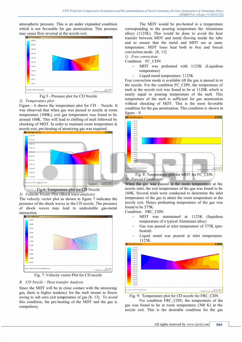
atmospheric pressure. This is an under expanded condition
which is not favorable for gas atomization. This pressure
may cause flow reversal at the nozzle exit.
Fig 5 - Pressure plot for CD Nozzle
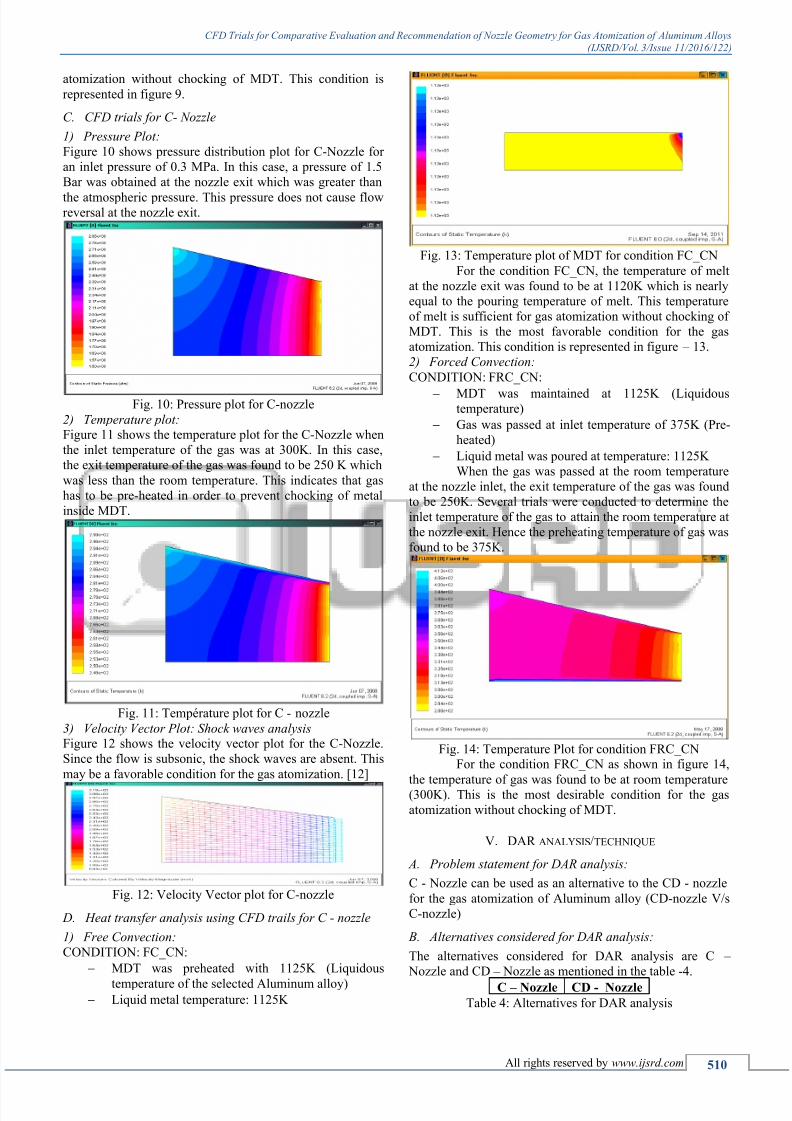
2) Temperature plot:
Figure - 6 shows the temperature plot for CD – Nozzle. Itwas observed that when gas was passed to nozzle at room
temperature (300K), exit gas temperature was found to be
around 160K. This will lead to chilling of melt followed bychocking of MDT. In order to maintain room temperature at
nozzle exit, pre-heating of atomizing gas was required.
Fig 6: Temperature plot for CD Nozzle
3) Velocity Vector Plot (Shock wave analysis)
The velocity vector plot as shown in figure 7 indicates the
presence of the shock waves in the CD nozzle. The presenceof shock waves may lead to undesirable gas-metal
interaction.
Fig. 7: Velocity vector Plot for CD nozzle
B. CD Nozzle – Heat transfer Analysis
Since the MDT will be in close contact with the atomizing
gas, there is higher tendency for the melt stream to freezeowing to sub zero exit temperature of gas [8, 13]. To avoid
this condition, the pre-heating of the MDT and the gas is
compulsory.
The MDT would be pre-heated to a temperature
corresponding to the pouring temperature the Aluminum
alloys (1125K). This would be done to avoid the heattransfer between MDT and metal flowing inside the tube
and to ensure that the metal and MDT are at same
temperature. MDT loses heat both in free and forced
convection mode. [8, 13]
1) Free convection:
Condition: FC_CDN
MDT was preheated with 1125K (Liquidous
temperature)
Liquid metal temperature: 1125K
Free convection mode is available till the gas is passed in to
the nozzle. For the condition FC_CDN, the temperature of
melt at the nozzle exit was found to be at 1120K which is
nearly equal to pouring temperature of the melt. This
temperature of the melt is sufficient for gas atomization
without chocking of MDT. This is the most favorable
condition for the gas atomization. This condition is shown in
figure – 8.
Fig. 8: Temperature plot for MDT for FC_CDN
2)
Forced Convection:When the gas was passed at the room temperature at thenozzle inlet, the exit temperature of the gas was found to be
160K. Several trials were conducted to determine the inlet
temperature of the gas to attain the room temperature at the
nozzle exit. Hence preheating temperature of the gas was
found to be 575K.
Condition: FRC_CDN:
MDT was maintained at 1125K (liquidous
temperature of a typical Aluminum alloy)
Gas was passed at inlet temperature of 575K (pre-
heated)
Liquid metal was poured at inlet temperature:
1125K
Fig. 9: Temperature plot for CD nozzle for FRC_CDN
For condition FRC_CDN, the temperature of thegas was found to be at room temperature (300 K) at the
nozzle exit. This is the desirable condition for the gas
7/21/2019 CFD Trials for Comparative Evaluation and Recommendation of Nozzle Geometry for Gas Atomization of Aluminu…
http://slidepdf.com/reader/full/cfd-trials-for-comparative-evaluation-and-recommendation-of-nozzle-geometry 4/6
CFD Trials for Comparative Evaluation and Recommendation of Nozzle Geometry for Gas Atomization of Aluminum Alloys
(IJSRD/Vol. 3/Issue 11/2016/122)
All rights reserved by www.ijsrd.com 510
atomization without chocking of MDT. This condition is
represented in figure 9.
C. CFD trials for C- Nozzle
1) Pressure Plot:
Figure 10 shows pressure distribution plot for C-Nozzle for
an inlet pressure of 0.3 MPa. In this case, a pressure of 1.5
Bar was obtained at the nozzle exit which was greater than
the atmospheric pressure. This pressure does not cause flowreversal at the nozzle exit.
Fig. 10: Pressure plot for C-nozzle
2) Temperature plot:Figure 11 shows the temperature plot for the C-Nozzle when
the inlet temperature of the gas was at 300K. In this case,
the exit temperature of the gas was found to be 250 K which
was less than the room temperature. This indicates that gas
has to be pre-heated in order to prevent chocking of metal
inside MDT.
Fig. 11: Température plot for C - nozzle
3) Velocity Vector Plot: Shock waves analysisFigure 12 shows the velocity vector plot for the C-Nozzle.
Since the flow is subsonic, the shock waves are absent. This
may be a favorable condition for the gas atomization. [12]
Fig. 12: Velocity Vector plot for C-nozzle
D. Heat transfer analysis using CFD trails for C - nozzle
1) Free Convection:
CONDITION: FC_CN:
MDT was preheated with 1125K (Liquidous
temperature of the selected Aluminum alloy) Liquid metal temperature: 1125K
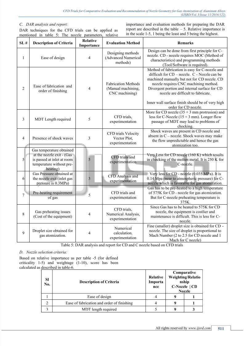
Fig. 13: Temperature plot of MDT for condition FC_CN
For the condition FC_CN, the temperature of melt
at the nozzle exit was found to be at 1120K which is nearly
equal to the pouring temperature of melt. This temperature
of melt is sufficient for gas atomization without chocking of
MDT. This is the most favorable condition for the gas
atomization. This condition is represented in figure – 13.
2) Forced Convection:
CONDITION: FRC_CN:
MDT was maintained at 1125K (Liquidoustemperature)
Gas was passed at inlet temperature of 375K (Pre-
heated)
Liquid metal was poured at temperature: 1125K
When the gas was passed at the room temperature
at the nozzle inlet, the exit temperature of the gas was found
to be 250K. Several trials were conducted to determine the
inlet temperature of the gas to attain the room temperature at
the nozzle exit. Hence the preheating temperature of gas was
found to be 375K.
Fig. 14: Temperature Plot for condition FRC_CNFor the condition FRC_CN as shown in figure 14,
the temperature of gas was found to be at room temperature(300K). This is the most desirable condition for the gas
atomization without chocking of MDT.
V. DAR ANALYSIS/TECHNIQUE
A. Problem statement for DAR analysis:
C - Nozzle can be used as an alternative to the CD - nozzle
for the gas atomization of Aluminum alloy (CD-nozzle V/s
C-nozzle)
B. Alternatives considered for DAR analysis:
The alternatives considered for DAR analysis are C –
Nozzle and CD – Nozzle as mentioned in the table -4.
C –
Nozzle CD - Nozzle
Table 4: Alternatives for DAR analysis
7/21/2019 CFD Trials for Comparative Evaluation and Recommendation of Nozzle Geometry for Gas Atomization of Aluminu…
http://slidepdf.com/reader/full/cfd-trials-for-comparative-evaluation-and-recommendation-of-nozzle-geometry 5/6
CFD Trials for Comparative Evaluation and Recommendation of Nozzle Geometry for Gas Atomization of Aluminum Alloys
(IJSRD/Vol. 3/Issue 11/2016/122)
All rights reserved by www.ijsrd.com 511
C. DAR analysis and report:
DAR techniques for the CFD trials can be applied as
mentioned in table 5: The nozzle parameters, relative
importance and evaluation methods for preparing the DAR
report are described in the table – 5. Relative importance is
in the scale 1-5, 1 being the least and 5 being the highest.
SL # Description of CriteriaRelative
ImportanceEvaluation Method Remarks
1 Ease of design 4
Designing methods
(Advanced Numerical
methods)
Design can be done from first principle for C-
nozzle. CD - nozzle requires MOC (Method of
characteristics) and programming methods(Tool/Software is required).
2Ease of fabrication and
order of finishing4
Fabrication Methods(Manual machining,
CNC machining)
Method of fabrication is easy for C-nozzle and
difficult for CD – nozzle. C - Nozzle can be
machined manually but not for CD nozzle. CD
nozzle requires CNC machining method.Divergent portion and internal surface for CD
nozzle are difficult to fabricate.
Inner wall surface finish should be of very high
order for CD nozzle.
3 MDT Length required 5
CFD trials,
experimentation
More for CD nozzle (35 + 3 mm protrusion) and
less for C-Nozzle (15 + 3 mm). Longer flow
passage of MDT may lead to problems ofchocking.
4 Presence of shock waves 3
CFD trials Velocity
Vector Plot,
experimentation
Shock waves are present in CD nozzle and
absent in C – nozzle. Shock waves may make
the flow unpredictable and hence the gas
atomization too.
5
Gas temperature obtained
at the nozzle exit - (Gas
is passed at inlet at room
temperature without pre-
heating)
5CFD trials and
experimentation
Very Less for CD nozzle (160 K) which results
in chocking of the molten metal. It is 250 K for
C-nozzle.
6
Gas Pressure obtained at
the nozzle exit (inlet gas
pressure is 0.3MPa)
3CFD Analysis and
experimentation
Very less for CD - nozzle (0.035 MPa). It is
0.14 Mpa (near to atmospheric pressure) for C-
nozzle which is favorable for gas atomization.
7Pre-heating requirement
of gas5
CFD trials and
experimentation
Gas has to be pre-heated to a high temperature
of 575K for CD - nozzle for gas atomization.
But for C-nozzle preheating temperature is
375K.
8Gas preheating issues
(Cost of the equipment)4
CFD trials,
Numerical Analysis,
experimentation
Since Gas has to be heated to 575K for CD
nozzle, the equipment is costlier and
maintenance is difficult. This is less for C-
nozzle.
9Droplet size obtained for
gas atomization.4
Numerical
calculation,
experimentation
Fine (smaller) droplet size is obtained for CD -
nozzle. The size of droplet is proportional to
Mach Number (2 to 2.5 for CD nozzle and 1
Mach for C nozzle)
Table 5: DAR analysis and report for CD and C nozzle based on CFD trials
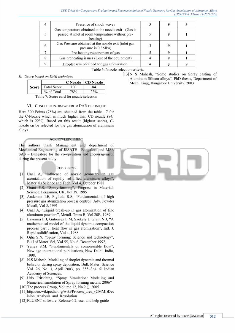
D. Nozzle selection criteria:
Based on relative importance as per table -5 (for definedcriticality 1-5) and weightage (1-10), score has been
calculated as described in table-6.
Sl
No.Description of Criteria
Relative
Importa
nce
Comparative
Weighting/Relatio
nship
C-Nozzle | CD
Nozzle
1 Ease of design 4 9 1
2 Ease of fabrication and order of finishing 4 9 1
3 MDT length required 5 9 3
7/21/2019 CFD Trials for Comparative Evaluation and Recommendation of Nozzle Geometry for Gas Atomization of Aluminu…
http://slidepdf.com/reader/full/cfd-trials-for-comparative-evaluation-and-recommendation-of-nozzle-geometry 6/6
CFD Trials for Comparative Evaluation and Recommendation of Nozzle Geometry for Gas Atomization of Aluminum Alloys
(IJSRD/Vol. 3/Issue 11/2016/122)
All rights reserved by www.ijsrd.com 512
4 Presence of shock waves 3 9 3
5
Gas temperature obtained at the nozzle exit - (Gas is
passed at inlet at room temperature without pre-
heating)
5 9 1
6Gas Pressure obtained at the nozzle exit (inlet gas
pressure is 0.3MPa)3 9 1
7 Pre-heating requirement of gas 5 9 1
8 Gas preheating issues (Cost of the equipment) 4 9 1
9 Droplet size obtained for gas atomization. 4 3 9
Table 6: Nozzle selection criteria
E. Score based on DAR technique
Score
C Nozzle CD Nozzle
Total Score 300 84
% of Total 78% 22%
Table 7: Score card for nozzle selection
VI. CONCLUSION DRAWN FROM DAR TECHNIQUE
Here 300 Points (78%) are obtained from the table - 7 for
the C-Nozzle which is much higher than CD nozzle (84,which is 22%). Based on this result (highest score), C-nozzle cn be selected for the gas atomization of aluminum
alloys.
ACKNOWLEDGEMENT
The authors thank Management and department of
Mechanical Engineering of JSSATE - Bangalore and MSR
SAS – Bangalore for the co-operation and encouragement
during the present study.
R EFERENCES
[1]
Unal A, “Influence of nozzle geometry in gasatomization of rapidly solidified aluminum alloys”,
Materials Science and Tech, Vol 4, October 1988
[2] Grant P.S, “Spray-forming”, Progress in Materials
Science, Pergamon, UK, Vol 39, 1995
[3] Anderson I.E, Figliola R.S, “Fundamentals of high
pressure gas atomization process control” Adv. PowderMetall, Vol 5, 1991
[4] Unal A, “Liquid break -up in gas atomization of fine
aluminum powders”, Metall. Trans B, Vol 20B, 1989
[5] Lavernia E.J, Gutierrez E.M, Szekely J, Grant N.J, “A
mathematical model of the liquid dynamic compaction
process part I: heat flow in gas atomization”, Intl. J.
Rapid solidification, Vol 4, 1988[6] Ojha S.N, “Spray forming: Science and technology”,
Bull of Mater. Sci, Vol 55, No. 6, December 1992,
[7] Yahya S.M, “Fundamentals of compressible flow”,
New age international publications, New Delhi, India,
1998.
[8] N.S Mahesh, Modeling of droplet dynamic and thermal
behavior during spray deposition, Bull. Mater. Science
Vol. 26, No. 3, April 2003, pp. 355 – 364. © Indian
Academy of Sciences.
[9] Udo Fritsching, “Spray Simulation: Modeling and
Numerical simulation of Spray forming metals: 2006”
[10] The process Group, Volume 12, No.2 (), 2005
[11]
http://en.wikipedia.org/wiki/Process_area_(CMMI)Decision_Analysis_and_Resolution
[12] FLUENT software, Release 6.2, user and help guide
[13] N S Mahesh, “Some studies on Spray casting of
Aluminum-Silicon alloys”, PhD thesis, Department of
Mech. Engg, Bangalore University, 2003