cfd study of a ducted cross flow turbine concept for...
TRANSCRIPT

NOMENCLATURE
A = initial turbine inlet size, m2
= tip speed ratio(TSR)
Cp = power coefficient
R = blade radius, m
VR = tidal current speed, m/s2
= angular velocity, m/s2
= density of water, kg/m3
U= tidal current speed, m/s2
1. Introduction
There are many forms of ocean energy that can be converted such
as tidal range, ocean currents, tidal currents, wave energy etc... From
these various types of ocean energy, marine current energy has the
advantage of having a predictable steady power output that can be
supplied over a long period of time. However, a disadvantage is that
the terrain distribution in various areas may affect the water speed
adversely and reduce it below the design speed. Since power output is
proportionally related to the cubic power of velocity, a lower velocity
in a certain area will decrease the feasibility of installation.
Therefore, more study is needed for the research and development of
low speed tidal turbines in order to increase the performance in low
speed areas and as well as improve the efficiency of tidal turbines in
suitably chosen sites.[1]
Previously, research was done on Bi-Directional cross flow
turbine by Kim et al.[1] It was seen that the augmentation channel
strongly influenced the flow and the turbine performance. In addition,
the flow resistance by the augmentation channel and the blades forced
the flow to divert away from the augmentation channel, reducing the
flow velocity and turbine efficiency.
In this paper, a duct was applied onto the previous Bi-directional
turbine to study the internal fluid flow of the duct and the turbine, the
influence on turbine performance according to the duct size and to
find an optimized duct by CFD in order to increase the efficiency of
the turbine.[1] In addition, the turbine performance variation with tip
speed ratio was investigated in order to obtain the highest efficiency
of the optimized duct. [1]
2. Conceptual design of the turbine system
2.1 Tip speed ratio (TSR)
The Tip speed ratio is an important design variable of the rotor
CFD study of a ducted cross flow turbine concept for high efficiency tidal current energy extraction
Incheol Kim1 ,Joji Wata1, M. Rafiuddin Ahmed2, Youngho Lee3,#
1 Graduate School, Dept. of Mechanical Engineering, Korea Maritime University, Busan, 606-791, Korea 2.Division of Mechanical Engineering, The University of the South Pacific, Suva, Fiji
3. Division of Mechanical and Energy Systems Engineering, Korea Maritime University, Busan, 606-791, Korea. # Corresponding Author / E-mail: [email protected], TEL: +82-51-410-4293, FAX: +82-51-403-0381
KEYWORDS : Tidal current energy; Cross-flow turbine; Renewable energy.
There is a growing interest in utilizing tidal current energy for power generation which has led to extensive research on this
source of renewable energy. The work presented here aims to study the tidal current energy extraction using a cross-flow
turbine. The bi-directional flow of tidal currents is used to drive a uni-directional cross-flow turbine. The cross-flow turbine
studied is placed in an augmentation channel, having a nozzle and a diffuser. The performance of the device is studied
numerically using the commercial ANSYS-CFX code. The internal flow characteristics of the turbine is studied for various
cases. Results of the numerical analysis are presented in terms of pressure contours, streaklines, velocity vectors, power
coefficient, and performance curves.
blade. The angular velocity can be calculated using equation (1).
In this equation, is the tip speed ratio, R is the blade radius, is
the angular velocity and VR is the design current velocity.
(1)
When the tip speed ratios is higher than the appropriate tip speed
ratio, vibration and cavitation will occur. On the other hand, at lower
tip speed ratios, the output power will be relatively small. The Tip
speed range near the highest CP point in the performance curves by
Tip speed requires a detailed analysis. The optimum Tip speed range
can be defined at about 80-90% on either side of the maximum Cp
point but the range can be differed according to the performance
curves. [1]
The cross flow turbine was made to achieve the highest CP at a tip
speed range near 1.[1]
2.2 Cross flow turbine model
In order to apply cross flow turbines for tidal power generation, it
is necessary for the fluid direction and angle to develop the optimum
angle of attack on the blade. As the working fluid enters the inlet and
if it completely fills the area of the turbine, part of the flow will cause
the rotation of the turbine whereas other parts will resist the rotation
in the opposite direction. This will reduce the output power of the
turbine. Therefore, the turbine is not fully exposed to the flow but the
flow must be guided via instead to rotate the turbine in the direction
of the blade. In addition, another important variable is the outlet angle
of the runner blade. If the outlet flow angle from the inlet is not
optimum, the flow may interfere with the rotation of the turbine near
the outlet and cause a decrease in power. [1]
To satisfy these necessary conditions, the nozzle was installed
into turbine inlet area. Also, to produce maximum torque, the design
of the blade and the angle of the nozzle to turbine inlet area was
considered.[1]
The blade length is 464 mm, the axial length is 3,200 mm, the
number of blade is 30 and the thickness of the blade is 26.24 mm. The
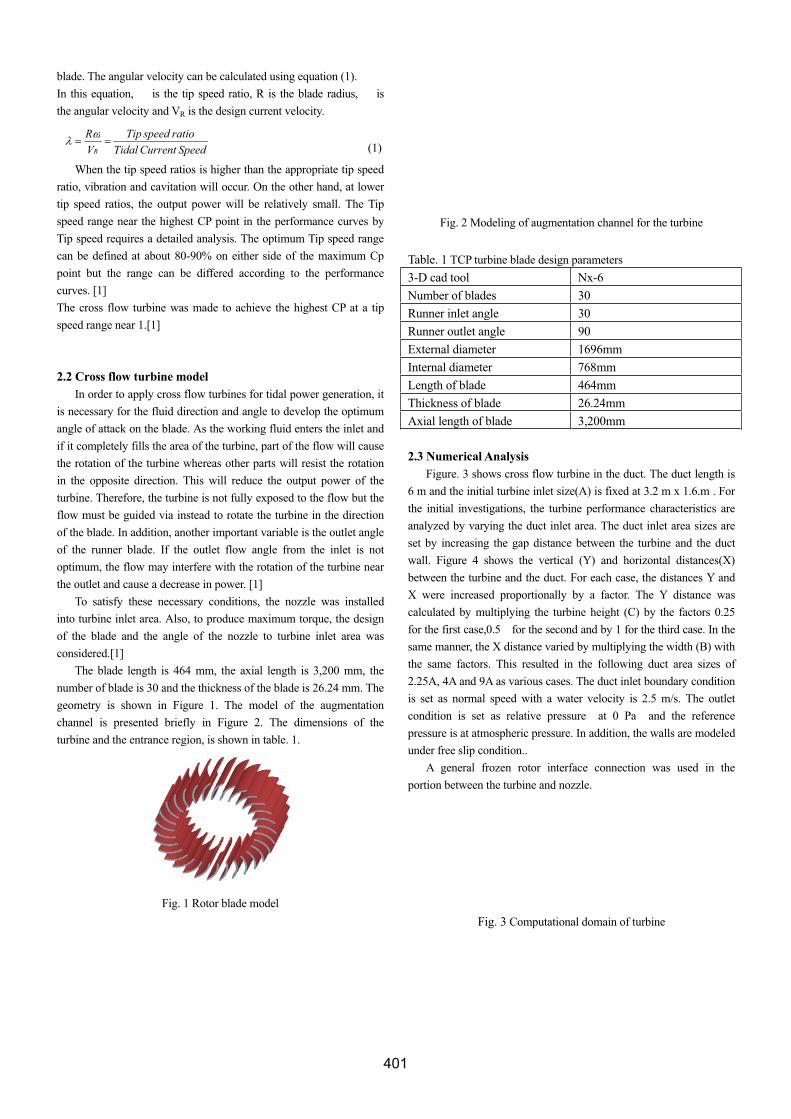
geometry is shown in Figure 1. The model of the augmentation
channel is presented briefly in Figure 2. The dimensions of the
turbine and the entrance region, is shown in table. 1.
Fig. 1 Rotor blade model
Fig. 2 Modeling of augmentation channel for the turbine
Table. 1 TCP turbine blade design parameters
3-D cad tool Nx-6
Number of blades 30
Runner inlet angle 30
Runner outlet angle 90
External diameter 1696mm
Internal diameter 768mm
Length of blade 464mm
Thickness of blade 26.24mm
Axial length of blade 3,200mm
2.3 Numerical Analysis
Figure. 3 shows cross flow turbine in the duct. The duct length is
6 m and the initial turbine inlet size(A) is fixed at 3.2 m x 1.6.m . For
the initial investigations, the turbine performance characteristics are
analyzed by varying the duct inlet area. The duct inlet area sizes are
set by increasing the gap distance between the turbine and the duct
wall. Figure 4 shows the vertical (Y) and horizontal distances(X)
between the turbine and the duct. For each case, the distances Y and
X were increased proportionally by a factor. The Y distance was
calculated by multiplying the turbine height (C) by the factors 0.25
for the first case,0.5 for the second and by 1 for the third case. In the
same manner, the X distance varied by multiplying the width (B) with
the same factors. This resulted in the following duct area sizes of
2.25A, 4A and 9A as various cases. The duct inlet boundary condition
is set as normal speed with a water velocity is 2.5 m/s. The outlet
condition is set as relative pressure at 0 Pa and the reference
pressure is at atmospheric pressure. In addition, the walls are modeled
under free slip condition..
A general frozen rotor interface connection was used in the
portion between the turbine and nozzle.
Fig. 3 Computational domain of turbine
SpeedCurrentTidal
ratiospeedTip
V
R
R

The analysis was first calculated for each case of duct size (2.25A,
4A, 9A) at 14RPM. From this simulation the best case was selected
to be analyzed further. At this duct size, the tip speed ratio was varied
from 0.8-1.4 and the turbine performance characteristics was further
analyzed .
The Torque and angular velocity calculated from this
simulation was used to calculate the Cp by using equation 4.
In the present analysis, hexahedral grids were generated to obtain
higher accuracy. The generated mesh is shown in Figures 5 to 6.The
total number of nodes at the blade section is approximately 900,000.
The augmentation channel section has approximately 500,000 nodes.
The number of nodes in the domain surrounding the turbine is
approximately 400,000. The total number of nodes was
approximately 1,800,000. To carry out the CFD analysis, 6 parallel
computers were used. A commercial CFD code of CFX-13 is adopted
to conduct CFD simulation to solve incompressible turbulent flow. To
achieve good convergence of the results, the k- is applied as the
turbulence model.
Fig. 4 Nomenclature of the turbine and Duct geometry
Fig. 5 Grid system of turbine
. Fig. 6 Grid system of runner
2.4 Results and Discussion
Figure 7-13 shows results of the analysis by duct size. The figures
7 to 9 shows velocity vectors from the duct inlet to the turbine and as
well as the flow around it. From these figures, the case with the
reduced turbine inlet area (2.25A) had the fastest flow velocity within
the turbine. Also, the figures show the flow separating from the top
side of the turbine due to the sharp corner. Whereas the flow follows
the casing at the bottom side of the inlet before separating near the
diffuser. The flow around turbine is accelerated through the gap
between the duct and turbine. The flow around the diffuser section is
seen to interact with the outflow from the diffuser. In the figure 7, the
high speed external flow influences the flow from the diffuser and the
flow is seen to become stable compared to figures 8 and 9. For future
investigations, a modified case with a straight external wall can be
used to accelerate the flow around the turbine in order to study the
effect on turbine performance.
The Pressure distribution contours at various inlet areas are
shown in figures 10-12. These figures show a high pressure region
near the inlet with the highest pressure recorded near the edges. As
the flow enters the turbine region, the velocity is seen to increase as
shown in previous figures. As this occurs the pressure is seen to
decrease. In addition, as the duct area increases, the pressure before
and inside the turbine inlet is decreased and the cases with the
increased duct area have a relatively lower maximum high pressure at
the turbine inlet. In the high pressure region, the velocity vectors had
shown a lower velocity than the duct inlet velocity of 2.5m/s. As the
water passes through the turbine and into the lower pressure region,
the velocity is seen to increase and in some areas have a higher
velocity than the duct inlet velocity. From these 3 cases, the case with
the highest pressure difference and higher velocity vectors is seen in
the 2.25A duct size case.
The performance curves of the 3 cases are shown in figure 13.
The best case was the 2.25A case with an efficiency of 0.563, a power
output of 22.46kW. From this figure, it was seen that as the duct area
increases, the performance characteristics of the turbine decreased.
Figure 14 shows power coefficient calculated from the torque of
five cases in the tip speed ratio range from 0.8 to 1.4 at the turbine
inlet size of 2.25A. The Cp was over 0.5 in tip speed ratio 0.8 to 1.4.
The maximum power coefficient 0.563 at a tip speed ratio of 0.99.
The rated RPM for this turbine is 14RPM at the design flow speed.
Fig. 7 Velocity vector at 2.25A duct size
3
21
AU
TCp

Fig. 8 Velocity vector at 4A duct size
Fig. 9 Velocity vector at 9A duct size
The performance curves are shown in Figure 15. The
performance curves, such as torque, are important for power systems
and generator design and control . The maximum torque of 17,429
Nm occurs at a tip speed ratio of 0.85 but the maximum output power
of 22.46 kW and Torque of 15321 Nm occurs at a tip speed ratio of
0.99
Fig. 10 Pressure contours of the flow area at 2.25A duct size
Fig. 11 Pressure contours of the flow area at 4A duct size
Fig. 12 Pressure contours of the flow area at 9A duct size
size of duct [A]
0 2 4 6 8 10
Cp
0.0
0.1
0.2
0.3
0.4
0.5
0.6
P[kW]
0
5
10
15
20
25
30
Torque[Nm]
0
2000
4000
6000
8000
10000
12000
14000
16000
18000
Cp
P[kW]
Torque[Nm]
Fig. 13 Performance curves according to size of duct
Fig. 14 Cp curve according to TSR

Fig. 15 Performance characteristics curve according to TSR
3. Conclusions
This study focused on the influence on the turbine performance
according to the variation of the duct size. The external casing shape
and external flow of duct was not considered but was taken as default
from the conceptual design stage from previous research. Figure 7 to
13 shows that as the duct size increases, the flow speed is reduced and
therefore it reduces the performance characteristics. The case with the
highest performance was the 2.25A duct size case. From figures 14
and 15, it was seen the optimum tip speed ratio for the 2.25A duct
size case was at TSR of 0.99.In addition, mixing effects between the
faster flow at the outside the casing and the outlet flow may have
increased flow speed of the outlet flow due to the gap and may have
improved performance. Therefore, the gap around the turbine casing
may have an significant influence. For future studies, The influence
of casing design on the external flow can be investigated.
ACKNOWLEDGEMENT
This work is the outcome of a Manpower Development Program
for Marine Energy by the Ministry of Land, Transport and Maritime
Affairs(MLTM)
REFERENCES
1. Kim, K., Ahmed, M., Hwang, Y. and Lee, Y., “Conceptual Design
of a 100kW Energy Integrated Type Bi-Directional Tidal Current
Turbine”, Proc. of the 10th AICFM. 2009, Paper 212.
2. CHOI, Y., LIM,J., KIM, Y., and Lee,Y., "Performance and
Internal Flow Characteristics of a Cross-flow Hydro Turbine by
the Shape of Nozzle and Runner Blade", J. of Fl. Sci. and Tech.
2008, Vol.3 NO.3, pp.398-409
3. Lim, J., “Blade configuration study to improve the performance
of horizontal axis tidal current turbine”, 2011 Inha Uni. master's
thesis
4. Kim, K., Ahmed, M., and Lee, Y., "Efficiency Improvement of a
tidal current turbine utilizing a larger area of channel", Ren. En.,
Volume 48, December 2012, Pages 557-564
5. Choi, Y., Kim, C., Kim, Y., Song, J., Lee, Y., "A performance
study on a direct drive hydro turbine for wave energy
converter." J. of Mech. Sci. and Tech. 2010;24:2197-206.