cfd pro 14.5 l06 local mesh controls
DESCRIPTION
CFDTRANSCRIPT
© 2013 ANSYS, Inc. December 12, 2013 1 Release 14.5
14. 5 Release
Introduction to ANSYS CFD Professional
Lecture 06 Local Mesh Controls

© 2013 ANSYS, Inc. December 12, 2013 2 Release 14.5
Meshing Process in ANSYS Meshing

© 2013 ANSYS, Inc. December 12, 2013 3 Release 14.5
Local Mesh Controls Control the mesh locally
• Depends on the “Mesh Method” used
Local Mesh Controls are:
• Sizing
– For Vertex, Edge, Face and Body
• Contact Sizing
– For Edge and face
• Refinement
– For Vertex, Edge and Face
• Mapped Face Meshing
– For Face
• Match Control
– For Edge and Face
• Pinch
– For Vertex and Edge
• Inflation
– For Edge and Face
The latest control added on a particular entity
overrides any prior controls

© 2013 ANSYS, Inc. December 12, 2013 4 Release 14.5
Sizing
Four Types of Sizing option
• Element Size specifies average element edge length on bodies, faces or edges
• Number of Divisions specifies number of elements on edge(s)
• Body of Influence specifies average element size within a body
• Sphere of Influence specifies average element size within the sphere
Sizing options vary depending on the entity type chosen
Entity/Option Element Size Number of Divisions Body of Influence Sphere of Influence
Vertices x
Edges x x x
Faces x x
Bodies x x x
Advanced Size
Function in Global
settings should be
disabled
Requires a
Coordinate
system for
the sphere

© 2013 ANSYS, Inc. December 12, 2013 5 Release 14.5
Sizing : Edges
Edge meshed with constant
element size of 60mm
Edge meshed with 10
elements
Sizing Type:
Element Size
Sizing Type: Number of Divisions
The Curvature Normal Angle displayed if ASF is
curvature sensitive. Growth Rate displayed for any
ASF.

© 2013 ANSYS, Inc. December 12, 2013 6 Release 14.5
Sizing : Edges Bias Type and Bias Factor
Specify the grading scheme and factor
• Bias Type: grading of elements towards one end, both ends, or the center
• Bias Option:
– Bias Factor: is the ratio of the largest element to the smallest element
– Smooth Transition: defined by Growth Rate which is ratio of size of an element to that of previous element.

© 2013 ANSYS, Inc. December 12, 2013 7 Release 14.5
Sizing : Edges Behaviour
Soft: Sizing will be influenced by global sizing functions such as those based on proximity and/or curvature as well as local mesh controls
Hard: Size control is strictly adhered to
Influenced by global
Proximity advanced
size function. Soft
Hard
No influence from other
global settings
• Transition between hard edges (or any edge with bias) and adjacent edge
and face meshes may be abrupt
• Hard edges or edges with bias will override Max Face Size and Max Size
properties

© 2013 ANSYS, Inc. December 12, 2013 8 Release 14.5
Element Size
Defines the maximum element size on the face
Face meshed with
constant element
size
Sizing : Faces
Edge curvature is
resolved
© 2013 ANSYS, Inc. December 12, 2013 9 Release 14.5
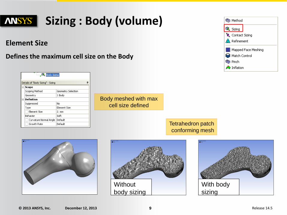
Element Size
Defines the maximum cell size on the Body
Sizing : Body (volume)
Body meshed with max
cell size defined
Without
body sizing
With body
sizing
Tetrahedron patch
conforming mesh

© 2013 ANSYS, Inc. December 12, 2013 10 Release 14.5
Sphere of Influence : on Vertex
– Available with or without Advanced Size Functions
– Sets the average element size around the selected vertex
– Inputs:
• Sphere radius and Element size
• Center of the sphere is defined by a model vertex
• Good resolution at the vertex
• The element size will be applied to all entities
connected to the selected vertex
Sizing : Sphere of Influence

© 2013 ANSYS, Inc. December 12, 2013 11 Release 14.5
Sphere of Influence : on Bodies
– Available with or without Advanced Size Functions
– Constant element size is applied within the confines of a sphere
– Use coordinate system to define the centre of the Sphere
Sizing : Sphere of Influence

© 2013 ANSYS, Inc. December 12, 2013 12 Release 14.5
Bodies of influence (BOI)
– Lines, surfaces and solid bodies can be used to refine the mesh
– Accessible when ASF is On
The ‘Body of Influence’ itself will not be meshed
Sizing : Bodies of Influence
Line BOIs
Surface BOI Solid BOI
Without BOIs
© 2013 ANSYS, Inc. December 12, 2013 13 Release 14.5
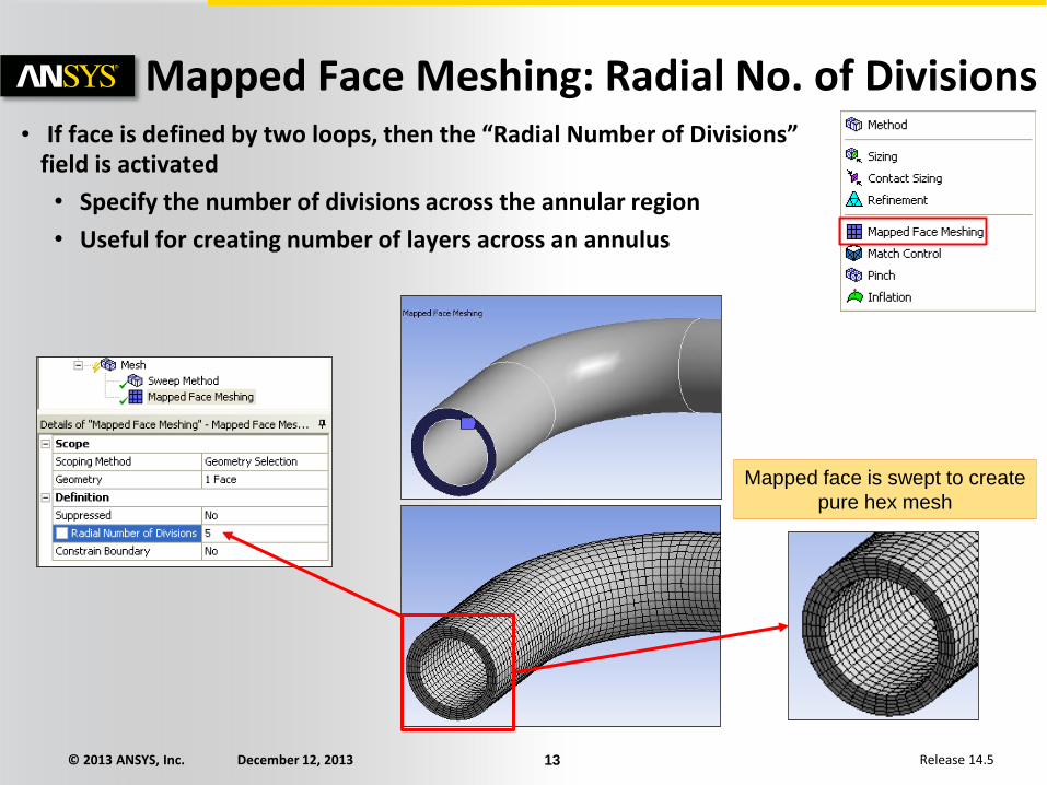
• If face is defined by two loops, then the “Radial Number of Divisions” field is activated
• Specify the number of divisions across the annular region
• Useful for creating number of layers across an annulus
Mapped Face Meshing: Radial No. of Divisions
Mapped face is swept to create
pure hex mesh

© 2013 ANSYS, Inc. December 12, 2013 14 Release 14.5
Used to generate prism layers (as explained in Global settings chapter)
Inflation layer can be applied to faces or bodies using respectively edges or faces as the boundary
Inflation
Inflation layer grown on edge boundary (red)
Inflation layer grown on face boundary (red)

© 2013 ANSYS, Inc. December 12, 2013 15 Release 14.5
Workshop 3 – Local Mesh Controls