cfd in medicine and life sciencesrlohner/pages/publications/papers/freiburg01.pdfcfd in medicine and...
TRANSCRIPT

CFD IN MEDICINE AND LIFE SCIENCES -
APPLICATIONS ON THE LIVING HUMAN BEING
Rainald L�ohner1, Juan Cebral1, Orlando Soto1, Peter Yim2, James E. Burgess3
1School of Computational Sciences and Informatics
M.S. 4C7, George Mason University, Fairfax, VA 22030-4444, USA2Diagnostic Radiology Department
National Institutes of Health, Bethesda, MD, USA3 INOVA
Fairfax Hospital, Fairfax, Virginia, USA
ABSTRACT
Recent advances in image segmentation, grid generation, ow solvers, realistic boundaryconditions, uid- structure interaction, data reduction and visualization are reviewedwith special emphasis on patient-speci�c ow prediction. At the same time, presentshortcomings in each one of these areas are identi�ed. Several examples are given thatshow that this methodology is maturing rapidly, and may soon �nd widespread use inmedicine.
KEY WORDS: Hemodynamics, Pulmonary Flows, CFD, Bioengineering
INTRODUCTION
Approximately 80% of the human body mass consists of water. The vascular system(arteries and veins) delivers nutrients and retrieves waste products. The respiratorysystem delivers oxygen and retrieves carbon dyoxide. These vital transport systemsare mainly tubular in nature, and are powered by the heart and lung respectively. Anykind of damage or obstruction of these transport systems will, in all likelihood, resultin a variety of diseases than can have a profound e�ect on wellness and quality of life.Vessel damage or obstruction may be treated by a variety of surgical and interventionalprocedures: stenting, balloon angioplasty, in situ drug delivery for unclotting, bypasssurgery, arti�cial organ implantation, etc. Many of these procedures are performeddaily on thousands of patients, and have led to an impressive empirical knowledgedatabase. Some of these procedures have statistically signi�cant failure rates, indicatinga need to study in depth the uid dynamics before and after the intervention. As inthe manufacturing industries, it would be highly desirable to predict the outcome ofan intervention before `cutting tissue', particularly for complex cases where a detailedempirical database is lacking.
1

The basic steps required for any type of ow simulation are the following:
- Pre-Processing or Problem De�nition:
- Geometry (Surface);
- Boundary and Initial Conditions;- Grid Generation;
- Fluid-Structure Solver; and
- Visualization and Data Reduction.
Any type of interventional simulation will require accurate modeling of patient-speci�canatomy and physiologic conditions. It is here where the biggest obstacle to routinesimulations lies. Typically, only the anatomy is imaged. Flows may be measurednon-invasively by PCMRA or ultrasound (US). However, the accuracy for these mea-surements can be problematic due to imaging artifacts and noise. The compliance of anarterial wall is di�cult to obtain, and its pressure/dilatation may be highly nonlinear.Nevertheless, recent advances in:
- Radiology (high contrast imaging);
- Image-to-surface de�nition tools;- Automatic grid generation;
- Fast incompressible ow solvers and realistic boundary conditions;
- Fluid-structure interaction techniques;- Insightful visualization;
- Validation in the form of in vitro/vivo studies; and
- Increased compute and graphics power
have led to a favourable con uence of techniques that have made predictions on theliving human being possible, and in some cases, routinely so.
In the sequel, we focus on recent advances, outstanding issues and obstacles for eachone of these areas. Thereafter, we show several examples to demonstrate that whatwas a vision several years ago is maturing rapidly and may indeed lead to medical toolsin the near future.
IMAGE-TO-SURFACE DEFINITION TOOLS
The starting point for most non-invasive patient-speci�c simulations is an image, i.e. anarray of pixels with di�erent colours. Imaging modalities currently in use are: DigitalSubtraction Angiography (DSA), Magnetic Resonance Angiography (MRA), ComputedTomography (CT), and Xenon-CT (XeCT). The overall quality (sharpness) of medicalimages depends not only on hardware factors (resolution, wavelength, etc.), but also ontype of contrast agent used, the skill of the radiologist and patient-speci�c factors. Thisimplies that in many cases, medical images will exhibit coarse resolution and noise, i.e.require considerable experience and/or `guessing' to be interpreted correctly. In orderto conduct any kind of ow simulation for the some or all of the vessels present in theimaged region, the surface of these vessels needs to be extracted. Numerous techniqueshave been explored over the last decade, of which we list a few here:
2

Active Contours: This most common approach consists in 2D image segmentationbased on edge detection, followed by slice interpolation, stacking and meshing [Bar96,Qua98, Tay98, Moo99]. Although there are many contour and edge detection operators,there is still no algorithm that can automatically extract region boundaries perfectlyfrom medical images [Kle96]. Besides, this technique requires a large amount of manualinput, and does not work properly for situations where the vessel is not perpendicularto the image slices (e.g. complex bifurcations and aneurysms).
Deformable Models: In this case, an initial, given shape is iteratively deformed by solv-ing an equivalent elastic problem driven by the image intensity gradient [Bur94, Vem96,Jon97]. The major drawback is that the initial shape (or skeleton) must have the sametopology as the reconstructed boundary. For simple vessels and bifurcations this isperhaps the best technique available. However, patient-speci�c simulations with com-plex geometries are di�cult, and in many instances this technique requires substantialhuman intervention, making the whole process tedious and time consuming.
Skeletonization and Deformable Models: These techniques assume that the surfaces tobe extracted are of tubular nature, i.e. have a skeleton of centerlines [Lee94, Kaw95].In a �rst step, these centerlines are extracted from the image. In a second step, thethickness of the vessels is obtained by `in ating' the centerlines in order to match thevessel boundaries. In some cases, each individual vessel is obtained separately, so thatthe complete vessel tree is obtained in a third step that joins the separate branches. Theend result is a triangulation that de�nes the vessel geometry. The amount of manual`guidance' varies from technique to technique, but can be considerable for some. Thistype of technique works very well for tubular structures, i.e. for most of the vascularsystem. However, it will not work well for regions where centerlines are not well de�ned,such are highly stenosed vessels or aneurysms.
Region Growing with Isosurface Extraction: These techniques interpret the pixels ofthe image as a mesh, i.e. with an undelying point and element structure. Given thelocal distribution of pixel intensity, an iso-surface of constant value can be obtained.The regions covered by the vessels of interest are obtained using region growing al-gorithms [Mas96, Wil97, Yim99, Dal99, Ceb99, Ceb00]. Starting from one or moreso-called seedpoints, all the voxels falling into the region of interest (typically given byan intensity threshold) are queried for a given intensity value. The iso-surface obtainedin this way is given as a triangulation.
None of the techniques outlined above is, at this point, universally applicable. Inparticular, images that exhibit vessels in close proximity can lead to wrong vessel in-terpretation. The automatic reconstruction of arterial trees involving several arterialgenerations also constitutes an unsolved problem. Perhaps a combination of di�er-ent techniques for di�erent entities (e.g. vessels, aneurysms, etc.) will lead to newbreakthroughs.The triangulation extracted from the medical image at hand, no matter which techniqueis being used, must be post-processed further. We mention:
3
a) Surface Improvement: Depending on the vessel surface extraction technique usedthe triangulations obtained can contain:
- Elements that have extremely large or small angles;- Small elements surrounded by much larger elements; and- Elements with large normal jumps between neighbours.
These elements are removed using edge or element collapse, as well as diagonal swapping[Hop93, Fre97, Ceb99, Ceb00].
b) Surface Smoothing: Depending on the vessel surface extraction technique used andthe image resolution, the triangulations obtained will exhibit bumps, sharp corners orother anormalities that are not present in the actual vessel. This implies that a surfacesmoothing step is required. A number of surface smoothing techniques have appearedin the literature. We have used the non-shrinking smoothing of Taubin [Tau95].
c) Branch Cutting: Vessels tend to become smaller and smaller as one progresses alongthe arterial tree. At some point, geometry resolution or ux resolution is insu�cient,and a boundary condition has to be applied to limit the computational domain. Thisimplies that a branch cutting tool has to be devised. Many techniques are possible.We have used iso-distance contours to cut branches interactively [Ceb99, Ceb00],
d) Construction of Post-Operational Models: Given the pre-operational anatomy, andthe expected modi�cation (e.g. due to stenting or bypass surgery), the post-operationalmodel can be constructed. This will involve surface merging, cutting, blending, etc.We have used iso-surface based techniques to perform such operations in an expedientway [Ceb01].
AUTOMATIC GRID GENERATION
Any �eld solver requires some form of volume discretization. Given their high degreeof exibility and automation, unstructured grids based on tetrahedra have been almostuniversally adopted for patient-speci�c vessel simulations. Recent advances in:
- Discrete surface gridding and- Minimal input grid generation
have enabled fully automatic grid generation of highly complex arterial and bronchialgeometries [Ceb00]. We mention a few of these advances in the sequel, as well asoutstanding issues for further investigation.
a) Discrete Surface Gridding: The vessel geometry is not de�ned as an analytical sur-face patch, but as a triangulation. This implies that robust automatic surface trian-gulation techniques that operate on discrete surface patches have to be devised. For anumber of years, we have used an advancing front technique on these discrete surfacepatches [L�oh96]. Recent improvements include: automatic preprocessing/improvementof the given discrete surface patch grid, the de�nition and enforcement of so-calledsharp edges, a strict enforcement of continuous topology, and improved front-crossingchecks [L�oh00, L�oh01].
4
b) Minimal Input Grid Generation: The de�nition of proper element size and shapefor arterial or bronchial trees with several braching generations can be a tedious, time-consuming process. In order to alleviate this problem, we have used adaptive back-ground grids based on the local discrete surface patch curvature [L�oh00, L�oh01]. Thisleads to grids where the number of elements per vessel diameter is always su�cient,without generating too many elements in the larger vessels.
As an outstanding research topic we mention the automatic generation of optimal gridsfor tubular structures. The idea here is to generate stretched elements along the maindirection of a vessel. This technique could potentially reduce the number of elementsand CPU time requirements by a factor of 1:5.
FAST INCOMPRESSIBLE FLOW SOLVERS
The equations describing incompressible ows may be written as
v;t + vrv +rp = r�rv ; (1)
r � v = 0 : (2)
Here p denotes the pressure, v the velocity vector and both the pressure p and theviscosity � have been normalized by the (constant) density �. Blood is a non-Newtonian uid, implying that the viscosity � depends on the strain rate tensor. The last twodecades have seen impressive progress in our ability to solve these equations in anexpedient manner. Key elements of any modern incompressible ow solver include:
- An Arbitrary Lagrangean-Eulerian (ALE) formulation for moving walls (deforminggrids);
- Implicit timestepping;- Some form of upwinding with limiters for the advection operator;- Satisfaction of the LBB condition for the divergence constraint, either via mixedelements [Tay73, For79], arti�cial dissipation [Fra89, Fra92, Tez90] or consistentnumerical uxes [L�oh99];
- Preconditioned iterative solvers [Wig85, Saa86, Ven88, Saa89] for all large systemsof equations that require inversion;
- Edge-based data structures for reduced indirect addressing and optimal operationcount [Luo94, L�oh01]; and
- Minimal cache misses, vectorization and parallelization options [L�oh98].
Further algorithmic gains may come from the use of LU-SGS preconditioning [Luo98,Luo01] and multigrid [Mav95, Mav96]. We have not seen the use of these techniquesfor medical ow applications, but see no reason why the success they have had in other�elds can not be duplicated here as well.
5

Boundary Conditions
The imposition of proper ow boundary conditions represents one of the most di�cult,and admittedly questionable, aspects of patient-speci�c simulations. In the �rst place,the ux data is not easy to obtain. Measuring velocity pro�les via Phase-Contrast MRA(PCMRA) requires non-standard imaging protocols and a longer scanning time. Thenthere is the question of resolution. The number of pixels required for accurate vesselgeometry reconstruction is much lower than the number of pixels required for accurate ow pro�le reconstruction. Only the velocity normal to the MRA cut is measured,i.e. a complete characterization of the velocity �eld would require even longer scanningtimes. For this reason only the velocity normal to a cut is measured, i.e. all cross-velocity information is lost. For some vessels, peak velocities can be measured usingultrasound techniques, and these can in turn be used to impose boundary conditions.On the other hand, we know that the ow in curved tubular structures can exhibitconsiderable cross ow, and that any form of cross ow can have signi�cant e�ectsdownstream.To date, most CFD simulations have been carried out prescribing fully developed, time-dependent velocity pro�les derived from ow-rate curves using the Womersley solution[Wom55]. The Womersley solution holds only for pulsating ow in an in�nitely longcircular cylinder. For other vessel cross-sections the Womersley pro�les are mappedaccordingly.Pressure boundary conditions are important for uid-structure interactions simulationswith compliant walls. Pressures can be obtained invasively using catheters, but it wouldbe highly desirable to develop non-invasive pressure measuring techniques.Major outstanding problems in this �eld are:a) The derivation of post-operative boundary conditions from pre-operative data[Tay01, Ceb01]; andb) The derivation of boundary conditions when complete information is unavailable.A typical case is the circle of Willis. We do not expect to be able to obtain complete ow and pressure data for this complex arterial system for years to come. Examplesof work in this area include vascular bed models [Ceb00] and the link of detailed 3-Dmodels with 1-D models of the whole cardiovascular system [Qua98].
6

STRUCTURAL DEFORMATION MODELS
Arterial wall movement will have a profound e�ect on local ow conditions. One ob-serves that uxes do not `add up' if the deformation of the wall is neglected. In principle,the vessel wall and the surrounding medium can be modeled using a structural dynam-ics solver for 3-D nonlinear, large-deformation behaviour. However, the di�culties inobtaining proper initial and boundary conditions are even more pronounced here thanfor the ow solver. The material is highly nonlinear, orthotropic, layered, may be re-sponding, etc. How to obtain this information non-invasively is, at this point, an openquestion. For this reason, most wall deformations have been computed using shells[Per95, Zha00] or, even simpler, an independent ring model [Qua98]. In this case, thenormal wall displacement � is obtained from:
m�;tt + d�;t + k� = p ; m = �wh ; k =Eh
(1 � �2)r2; (3)
where �w; h; r;E; � denote, respectively, the wall density, thickness, vessel radius,Young's modulus and Poisson ratio. This equation is integrated using a second-orderimplicit time integration scheme. As stated before, measuring h; r;E; � is no simplematter [Zha00, Lad01].
FLUID-STRUCTURE INTERACTION TECHNIQUES
Given that vessel deformation plays an important role for local ux evaluations, the uid and structure models must be combined. Due to their generality, modularityand extendability so-called loose coupling techniques have been used extensively inengineering (see, e.g. [Bau96]). The key idea is to have a master code that invokes the uid and structural codes alternatively in such a way that a minimum of changes arerequired for the latter. All data transfer is handled by a separate library. We remarkthat this is not only a matter of fast interpolation techniques [L�oh95, Mam95], butalso of accuracy, load conservation [Ceb97], geometrical �delity [Ceb97], and temporalsynchronization [Les96, Ceb97]. For implicit CFD and CSD codes, we use the followingunderrelaxed predictor- corrector scheme for each timestep:
7
while: not converged:
update structure with fluid loads:
xis = (1 � �)xi�1s + �f(�if )
update fluid with structure position/velocity:
�if = (1� �)�i�1
f + �g(xis)endwhile
Typical underrelaxation factors are in the range 0:5 � � � 0:9. Current research inthis area is focused on convergence criteria and acceleration techniques.
INSIGHTFUL VISUALIZATION
In order to enhance the understanding and prediction capability of patient-speci�csimulations, the results obtained must be presented in a form easily accessible to themedical community. In the particular case of tubular structures, many classic visual-ization techniques fail to o�er insight. This is because iso-surfaces or plane cut, staplesin the engineering world, become meaningless. A plane cut through a twisted, windingarterial or bronchial tree will lead to a few scattered ellipsoids here and there thato�er no insight on uxes, pressures, etc. For this reason, we have developed specializedreduction techniques [Ceb01] that work with the skeleton of the tubular structure inorder to display:
- Plane cuts normal to the skeleton;- Plane cuts along the skeleton;- Fluxes along the skeleton;- Iso-distance to wall surfaces; etc.
These reduction techniques have proven extremely bene�cial in identifying important ow features such as local recirculation zones and ow rates. Other techniques thathave found widespread use in computational hemodynamics include particle tracing(where there is an immediate mental connection to blood cells) and the use of transportequations to observe the dispersion of tracers.
VALIDATION
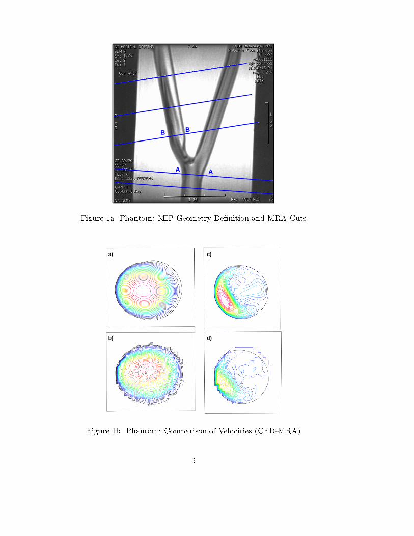
In order to validate at least partially the methodology developed to date, a phantomglass model of a cartid bifurcation with 65% stenosis in the internal carotid arterywas measured and computed. The model, as well as the cuts used for MRA owmeasurements are shown in Figure 1a. The CFD model was generated from the MRAdata. The discrepancy in the radii obtained from image processing and segmentationwas less than 2%. Parabolic velocity pro�les based on measured uxes were prescribedat the entrance and exit of the external carotid. Figure 1b shows a comparison of theabsolute value of the velocities (CFD) and the normal velocity measured (MRA) forthe cuts labeled A-A, B-B in Figure 1a. One can clearly see how coarse the resolutionof the MRA is. Figure 1c shows the absolute value of the velocity in the centerplaneand the streamlines. Note the large recirculation zone present.
8
A A
B B
Figure 1a Phantom: MIP Geometry De�nition and MRA Cuts
a)
b)
c)
d)
Figure 1b Phantom: Comparison of Velocities (CFD-MRA)
9

a) b)
Figure 1c Phantom: Abs(Vel) in Plane and Streamlines
Figure 2a Circle of Willis: Zhemo User Interface
10

EXAMPLES
E.1 Circle of Willis: The aim of this simulation was to assess the e�ect of clippingan artery in the circle of Willis on the overall ow pattern. Figure 2a shows thegraphical interface used for image processing, segmentation, surface extraction andsurface improvement. One can clearly discern the maximum intensity projection (MIP)on the upper left side, as well as two other cuts and the main 3-D window with theextracted and cut surface. The surface mesh is shown in Figure 2b. The volumemesh had approximately 4 million tetrahedra. Figure 2c shows streamribbons for anunclipped (left) and clipped (right) artery.
Figure 2b Circle of Willis: Surface Mesh
Figure 2c Circle of Willis: Strearibbons for Open and Clipped Cases
E.2 Carotid Bifurcation: This case shows the need to couple uid and structural codesto predict arterial ows. The anatomical data was taken from a normal human subject.A model of the right carotid artery of the subject was reconstructed from contrast-
11
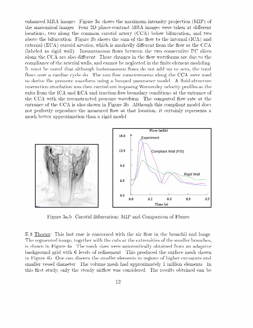
enhanced MRA images. Figure 3a shows the maximum intensity projection (MIP) ofthe anatomical images. Four 2D phase-contrast MRA images were taken at di�erentlocations, two along the common carotid artery (CCA) below bifurcation, and twoabove the bifurcation. Figure 3b shows the sum of the ow to the internal (ICA) andexternal (ECA) carotid arteries, which is markedly di�erent from the ow at the CCA(labeled as rigid wall). Instantaneous ows between the two consecutive PC slicesalong the CCA are also di�erent. These changes in the ow waveforms are due to thecompliance of the arterial walls, and cannot be neglected in the �nite element modeling.It must be noted that although instantaneous ows do not add up to zero, the total ows over a cardiac cycle do. The two ow measurements along the CCA were usedto derive the pressure waveform using a lumped parameter model. A uid-structureinteraction simulation was then carried out imposing Womersley velocity pro�les at theexits from the ICA and ECA and traction-free boundary conditions at the entrance ofthe CCA with the reconstructed pressure waveform. The computed ow rate at theentrance of the CCA is also shown in Figure 3b. Although this compliant model doesnot perfectly reproduce the measured ow at that location, it certainly represents amuch better approximation than a rigid model.
Compliant Wall (FSI)
Rigid Wall
Experiment
Figure 3a,b Carotid Bifurcation: MIP and Comparison of Fluxes
E.3 Thorax: This last case is concerned with the air ow in the bronchii and lungs.The segmented image, together with the cuts at the extremities of the smaller branches,is shown in Figure 4a. The mesh sizes were automatically obtained from an adaptivebackground grid with 6 levels of re�nement. This produced the surface mesh shownin Figure 4b. One can discern the smaller elements in regions of higher curvature andsmaller vessel diameter. The volume mesh had approximately 1 million elements. Inthis �rst study, only the steady air ow was considered. The results obtained can be
12

seen in Figures 4c,d, which show surface pressures and iso-surfaces of constant absolutevalue of velocity.
Figure 4a,b Thorax: Segmented Image and Surface Mesh
Figure 4c,d Thorax: Surface Pressures and Iso-Surfaces of Abs(Velocity)
13

CONCLUSIONS AND OUTLOOK
The ability to predict accurately ows in the vascular and pulmonary system on apatient-speci�c basis has increased dramatically in the last years. We expect progress tocontinue in all the areas that encompass a comprehensive simulation capability: imagesegmentation, grid generation, ow solvers, uid- structure interaction, data reductionand visualization. Some of the outstanding questions involve boundary conditions,material parameters (in particular for wall compliance), and the clinical signi�cance ofparticular ow phenomena.At present, image-based, patient-speci�c computational hemodynamics can be used to
- Study vascular diseases;- Enhance diagnosis; and
- Plan surgical procedures.Imaging modalities will continue to evolve and eventually both anatomy and physiologywill be accurately visualized. However, the power of computer simulations lies in theirability to predict the outcome of procedures, i.e. the answer to `what if' questions thatcan be useful for optimizing therapies.
Looking into the more distance future, we foresee:
- CFD enhanced radiology;
- Simulations of long-terms e�ects, such as plaque formation;- Simulations of drug delivery and e�ects; and- The coupling of ow codes (continuum level) and particle codes (molecular level).
REFERENCES
[Bar96] G. Barequet, D. Shapiro and A. Tal - History Consideration in ReconstructingPolyhedral Surfaces from Parallel Slices; Proc. IEEE Visualization'96, San Francisco,149-156 (1996).[Bau96] J.D. Baum, H. Luo, R. L�ohner, C. Yang, D. Pelessone and C. Charman - ACoupled Fluid/Structure Modeling of Shock Interaction with a Truck; AIAA-96-0795(1996).[Bur94] V. Burdin and C. Roux - Surface Segmentation of Long Bone Structures fromCT Images using a Deformable Contour Model; Proc. of 16th Annual Int. Conf. IEEEEng. in Medicine and Biology Society, Nov. 3-6, Baltimore (1994).
[Ceb97] J.R. Cebral and R. L�ohner - Conservative Load Projection and Tracking forFluid-Structure Problems; AIAA J. 35, 4, 687-692 (1997a).[Ceb97] J.R. Cebral and R. L�ohner - Fluid-Structure Coupling: Extensions and Im-provements; AIAA-97-0858 (1997b).[Ceb99] J. Cebral and R. L�ohner - Advances in Visualization: Distribution and Collab-oration; AIAA-99-0693 (1999).[Ceb99] J. Cebral and R. L�ohner - From Medical Images to CFD Meshes; Proc. 8thInt. Meshing Roundtable, South Lake Tahoe, October (1999).
14

[Ceb00] J.R. Cebral and R. L�ohner - Automatic Grid Generation for AnatomicallyAccurate Computational Hemodynamics Calculations; Proc. ICMMB-11, April 2-5,Hawaii (2000).
[Ceb00] J.R. Cebral and R. L�ohner - Image-Based Computational Hemodynamics; Proc.World Congress in Medical Physics and Biomedical Engineering, Chicago, Illinois, July23-28 (2000).
[Ceb00] J.R. Cebral, R. L�ohner and J. Burgess - Computer Simulation of CerebralArtery Clipping: Relevance to Aneurysm Neuro-Surgery Planning; Proc. of ECCOMAS2000 Conf. , Barcelona, Spain, September (2000).
[Ceb01] J. Cebral and R. L�ohner - Flow Visualization on Unstructured Grids UsingGeometrical Cuts, Vortex Detection and Shock Surfaces; AIAA-01-0915 (2001).
[Ceb01] J. Cebral Cebral JR, Lohner R, Choyke PL and Yim PJ, "Merging of inter-secting Triangulations for Finite Element Modeling", J. Biomech., in press 2001.
[Dal99] A.M. Dale, B. Fischl and M.I. Sereno - Cortical Surface-Based Analysis I:Segmentation and Surface Reconstruction; NeuroImage, 9(2), 179-194 (1999).
[For79] M. Fortin and F. Thomasset - Mixed Finite Element Methods for IncompressibleFlow Problems; J. Comp. Phys. 31, 113-145 (1979).
[Fra89] L.P. Franca, T.J.R. Hughes, A.F.D. Loula and I. Miranda - A New Familyof Stable Elements for the Stokes Problem Based on a Mixed Galerkin/Least-SquaresFinite Element Formulation; pp. 1067-1074 in Proc. 7th Int. Conf. Finite Elements inFlow Problems (T.J. Chung and G. Karr eds.), Huntsville, AL (1989).
[Fra92] L.P. Franca and S.L. Frey - Stabilized Finite Element Methods: II. The in-compressible Navier-Stokes Equations; Comp. Meth. Appl. Mech. Eng. 99, 209-233(1992).
[Fre97] P.J. Frey and H. Borouchaki, - Surface Mesh Evaluation; Proc. 6th Int. MeshingRoundtable, October 13-15, Park City, Utah (1997).
[Hop93] H. Hoppe, T. DeRose, T. Duchamp, J. McDonald, and W. Stuetzle - MeshOptimization; SIGGRAPH 93 Proceedings, 19-26 (1993).
[Jon97] T.N. Jones and D. Metaxas, - Automated 3D Segmentation Using DeformableModels and Fuzzy A�nity; Lecture Notes in Computer Sciences, V.1230, Springer-Verlag (1997).
[Kaw95] Y. Kawata, N. Niki and T. Kumazaki, - Computer-Assisted Analysis and3D Visualization of Blood Vessels Based on Cone-Bean CT Images; Lecture Notes inComputer Science, V.1024, 355-362 (1995).
[Kle96]] R. Klette and P. Zamperoni - Handbook of Image Processing Operators; JohnWiley & Sons, New York (1996).
[Lad01] Ladak HM, Thomas JB, Mitchell JR, Rutt BK, Steinman DA. A semi-automatic technique for measurement of arterial wall from black blood MRI. MedPhys, In Press
[Lee94] C.T. Lee, R.L. Kashyap and C.N. Chu - Building Skeleton Models Via 3DMedial Surface/Axis Thinning Algorithms; Graphical Models and Image Processing,56, 462-478 (1994).
15

[Les96] M. Lesoinne and Ch. Farhat - Geometric Conservation Laws for Flow ProblemsWith Moving Boundaries and Deformable Meshes, and Their Impact on AeroelasticComputations; Comp. Meth. Appl. Mech. Eng. 134, 71-90 (1996).
[L�oh95] R. L�ohner - Robust, Vectorized Search Algorithms for Interpolation on Un-structured Grids; J. Comp. Phys. 118, 380-387 (1995).
[L�oh96] R. L�ohner - Regridding Surface Triangulations; J. Comp. Phys. 126, 1-10(1996).[L�oh96] R. L�ohner - Extensions and Improvements of the Advancing Front Grid Gen-eration Technique; Comm. Num. Meth. Eng. 12, 683-702 (1996).
[L�oh98] R. L�ohner - Renumbering Strategies for Unstructured-Grid Solvers Operatingon Shared-Memory, Cache-Based Parallel Machines; Comp. Meth. Appl. Mech. Eng.163, 95-109 (1998).[L�oh99] R. L�ohner, Chi Yang, E. O~nate and S. Idelssohn - An Unstructured Grid-Based,Parallel Free Surface Solver; Appl. Num. Math. 31, 271-293 (1999).
[L�oh00] R. L�ohner - Advances in Unstructured Grid Generation; Proc. of ECCOMAS2000 Conf. , Barcelona, Spain, September (2000).
[L�oh01] R. L�ohner, Chi Yang, J. Cebral, O. Soto, F. Camelli, J.D. Baum, H. Luo, E.Mestreau, D. Sharov, R. Ramamurti, W. Sandberg and Ch. Oh - Advances in FEFLO;AIAA-01-0592 (2001).
[Luo94] H. Luo, J.D. Baum and R. L�ohner - Edge-Based Finite Element Scheme forthe Euler Equations; AIAA J. 32, 6, 1183-1190 (1994).
[Luo98] H. Luo, J.D. Baum and R. L�ohner - A Fast, Matrix-Free Implicit Method forCompressible Flows on Unstructured Grids; J. Comp. Phys. 146, 664-690 (1998).[Luo01] H. Luo, J.D. Baum and R. L�ohner - An Accurate, Fast, Matrix-Free ImplicitMethod for Computing Unstready Flows on Unstructured Grids; Comp. and Fluids 30,137-159 (2001).
[Mam95] N. Maman and C. Farhat - Matching Fluid and Structure Meshes for Aeroe-lastic Computations: A Parallel Approach; Computers and Structures 54, 4, 779-785(1995).
[Mas96] Y. Masutani, K. Masamune and T. Dohi, - Region-Growing Based Feature De-tection Algorithm for Tree-Like Objects; Lecture Notes in Computer Science, V.1131,161-172 (1996).
[Mav95] D. Mavriplis - A Uni�ed Multigrid Solver for the Navier-Stokes Equations onUnstructured Meshes; AIAA-95-1666 (1995).
[Mav96] D. Mavriplis - A 3-D Agglomeration Multigrid Solver for the Reynolds-Averaged Navier-Stokes Equations on Unstructured Meshes; Int. J. Num. Meth. Fluids23, 527-544 (1996).
[Moo99] J.A. Moore, D.A. Steinman, D.W. Holdsworth and C.R. Ethier - Accuracyof Computational Hemodynamics in Complex Arterial Geometries Reconstructed fromMagnetic Resonance Imaging; Annals of Biomed. Eng. 27, 32-41 (1999).
[Per95] K. Perktold and G. Rappitsch - Computer Simulation of Arterial Blood Flow.Vessels Diseases Under the Aspect of Local Hemodynamics; pp. 83-114 in Biological
16

Flows (M.Y. Ja�rin and C. Caro eds.), Plenum Press (1995).[Qua98] A. Quarteroni, M. Tuveri and A. Veneziani - Computational Vascular FluidDynamics: Problems, Models and Methods; Rep. EPFL/DMA 11.98 (1998).[Saa86] Y. Saad and M.H. Schultz - GMRES: A Generalized Minimal Residual Algo-rithm for Solving Nonsymmetric Linear Systems; Siam J. Sci. Stat. Comp. 7, 3, 856-869(1986).[Saa89] Y. Saad, - Krylov Subspace Methods on Supercomputers; Siam J. Sci. Stat.Comp. 10, 6, 1200-1232 (1989).[Tau95] G. Taubin - A Signal Processing Approach to Fair Surface Design; ComputerGraphics Proceedings, 351-358 (1995).[Tay73] C. Taylor and P. Hood - A Numerical Solution of the Navier-Stokes EquationsUsing the Finite Element Method. Comp. Fluids 1, 73-100 (1973).[Tay98] C.A. Taylor, T.J.R. Hughes and C.K. Zarins - Finite Element Modeling ofBlood Flow in Arteries; Comp. Meth. Appl. Mech. Eng. 158, 155-196 (1998).[Tez90] T.E. Tezduyar, R. Shih, S. Mittal and S.E. Ray - Incompressible Flow Computa-tions With Stabilized Bilinear and Linear Equal-Order Interpolation Velocity-PressureElements; UMSI Rep. 90 (1990).[Yim00] P.J. Yim, R. Mullick, R.M. Summers, H. Marcos, J.R. Cebral, R. L�ohner andP.L. Choyke - Measurement of Stenosis from Magnetic Resonance Angiography UsingVessel Skeletons; Proc. of SPIE, Vol 3978, p245-255, (2000).[Vem96] B.C. Vemuri, Y. Guo, S.H. Lai and C.M. Leonard, - Fast Algorithms forFittingMultiresolution Hybrid Shape Models to BrainMRI; Lecture Notes in ComputerScience, V.1131, 213-222 (1996).[Ven88] V. Venkatakrishnan - Newton Solution of Inviscid and Viscous Problems;AIAA-88-0413 (1988).[Wig85] L.B. Wigton, N.J. Yu and D.P. Young - GMRES Acceleration of ComputationalFluid Dynamics Codes; AIAA-85-1494-CP (1985).[Wil97] D.L. Wilson and J.A. Noble - Segmentation of Cerebral Vessels and Aneurysmsfrom MR Agiographic Data; Lecture Notes in Computer Science, V.1230, 423-428(1997).[Wom55] J.R. Womersley - Method for the Calculation of Velocity, Rate of Flow andViscous Drag in Arteries When the Pressure Gradient is Known; J. Physiol. 127,553-563 (1955).[Yim99] O. Yim and R.M. Summers - Analytic Surface Reconstruction by Local Thresh-old Estimation in the Case of Simple Intensity Contrasts; Proc. SPIE Medical Imaging,Vol. 3660, 288-300 (1999).[Zha00] S.Z. Zhao, X.Y. Xu, A.D. Hughes S.A. Thom, A.V. Stanton, B. Ari� and Q.Long - Blood Flow and Vessel Mechanics in a Physiologically Realistic Model of aHuman Carotid Arterial Bifurcation; J. Biomech. 33, 975-984 (2000).
17