cfd in comsol multiphysics - kth€¦ · comsol approach to modeling fluid flow chemical reactions...
TRANSCRIPT

CFD in COMSOL Multiphysics
Christian Wollblad
© Copyright 2017 COMSOL. Any of the images, text, and equations here may be copied and modified for your own internal use. All trademarks are the property of their respective owners. See www.comsol.com/trademarks.
Worldwide Sales Offices

CFD – The Classical View• Laminar• Turbulent
– RANS– LES– ....
• Incompressible• Compressible
– Mach number effects
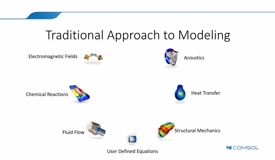
Traditional Approach to Modeling
Fluid Flow
Chemical Reactions
AcousticsElectromagnetic Fields
Heat Transfer
Structural Mechanics
User Defined Equations
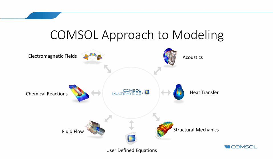
COMSOL Approach to Modeling
Fluid Flow
Chemical Reactions
AcousticsElectromagnetic Fields
Heat Transfer
Structural Mechanics
User Defined Equations

Typical Multiphysics Couplings• Flow with heat transfer: Non‐isothermal flow/Conjugate heat
transfer
• Flow with mass transfer: Reacting flow
• Flow and structures: Fluid‐Structure Interaction (FSI)
• Flow with particles: Particle tracing

Conjugate Heat Transfer ‐ Example• The model examines the air cooling of a
power supply unit (PSU) with multiple electronics components acting as heat sources.
• Avoid damaging components by excessively high temperatures
• Extracting fan and a perforated grille cause an air flow in the enclosure. Fins are used to improve cooling efficiency. Cooling of a Power Supply Unit (PSU)
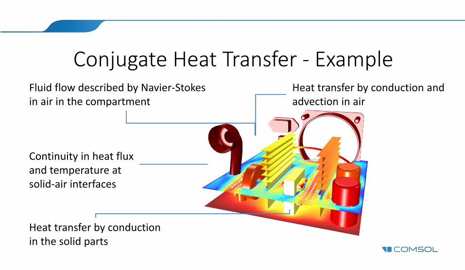
Conjugate Heat Transfer ‐ ExampleFluid flow described by Navier‐Stokesin air in the compartment
Heat transfer by conductionin the solid parts
Heat transfer by conduction and advection in air
Continuity in heat fluxand temperature atsolid‐air interfaces
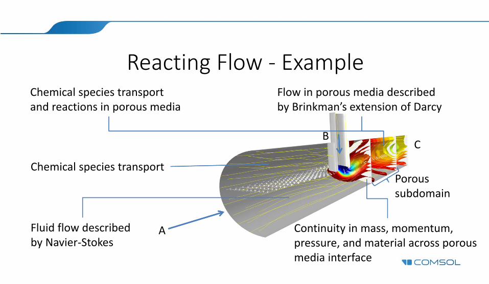
Reacting Flow ‐ ExampleChemical species transportand reactions in porous media
Chemical species transport
Flow in porous media describedby Brinkman’s extension of Darcy
Continuity in mass, momentum, pressure, and material across porous media interface
Fluid flow described by Navier‐Stokes
Poroussubdomain
A
BC
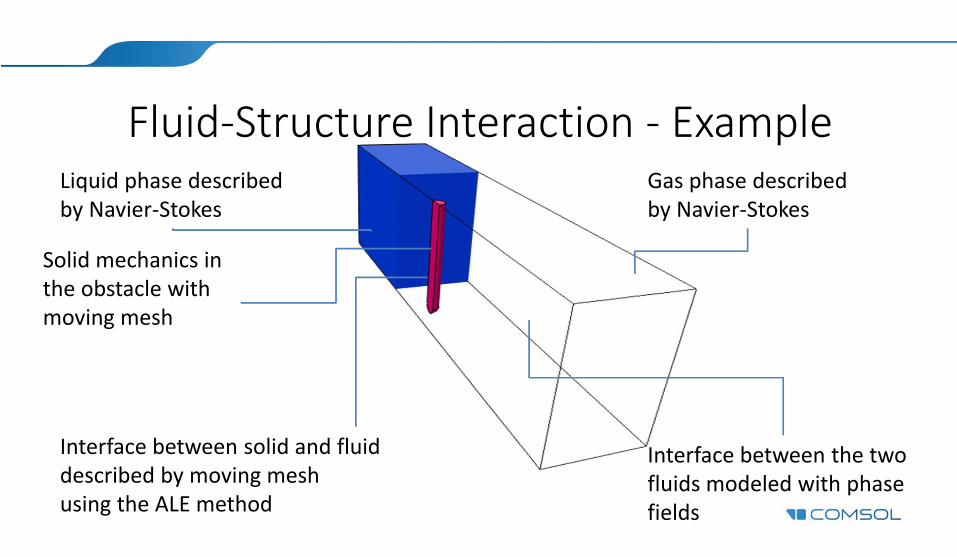
Fluid‐Structure Interaction ‐ ExampleLiquid phase describedby Navier‐Stokes
Solid mechanics inthe obstacle withmoving mesh
Gas phase describedby Navier‐Stokes
Interface between the twofluids modeled with phase fields
Interface between solid and fluid described by moving meshusing the ALE method
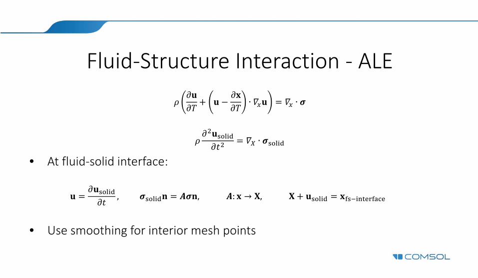
Fluid‐Structure Interaction ‐ ALE
∙ ∙
∙
• At fluid‐solid interface:
, , : → ,
• Use smoothing for interior mesh points
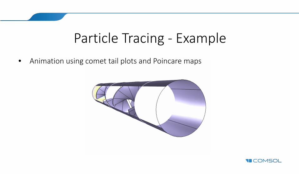
Particle Tracing ‐ Example• Animation using comet tail plots and Poincare maps

The Finite Element Method• General PDE: 0• Assume that ∑ (1)
Where is a set of trial functions.
(1) is a Fourierexpansion
Spectral methods
is a polynomial in each mesh cell
Finite elements
is a constant value for each cell/node
Finite volumesis piecewise constant
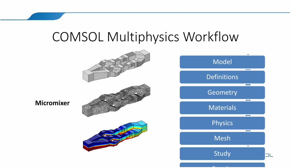
COMSOL Multiphysics Workflow
Micromixer
Model
Definitions
Geometry
Materials
Physics
Mesh
Study
R lt
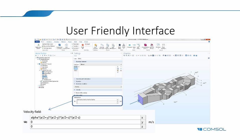
User Friendly Interface
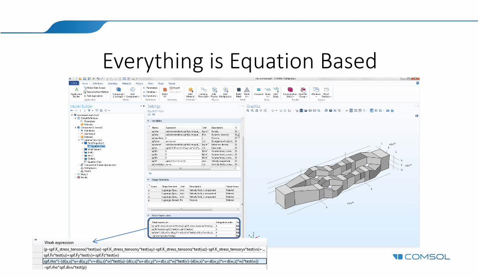
Everything is Equation Based
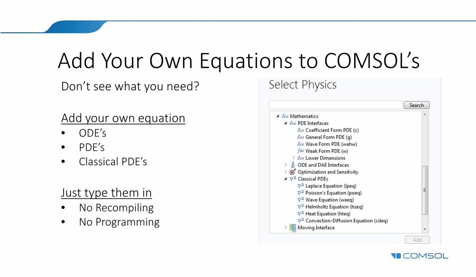
Add Your Own Equations to COMSOL’sDon’t see what you need?
Add your own equation• ODE’s• PDE’s• Classical PDE’s
Just type them in• No Recompiling• No Programming
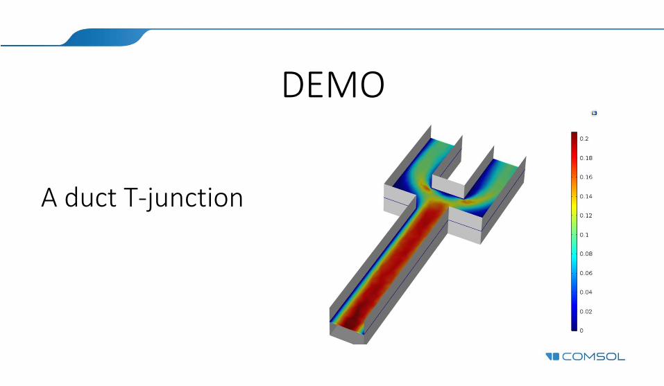
DEMO
A duct T‐junction
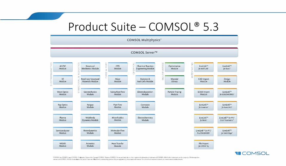
Product Suite – COMSOL® 5.3

Single‐Phase Flow• Creeping flow/Stokes flow• Laminar flow• Turbulent flow• Rotating machinery• Utility boundary conditions
– Fully developed flow– Screens– Grilles– Fans– Vacuum pump
A spinning soccer ballA spinning soccer ball
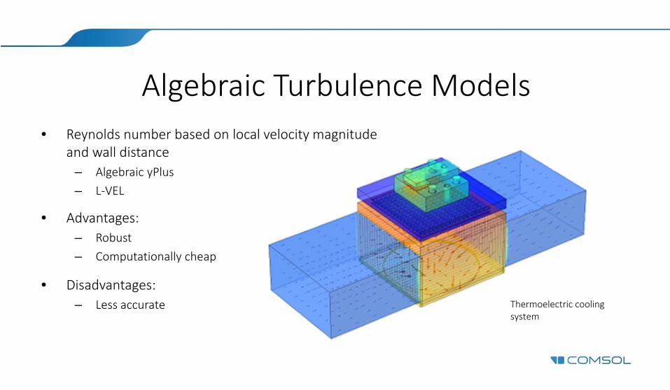
Algebraic Turbulence Models• Reynolds number based on local velocity magnitude
and wall distance– Algebraic yPlus– L‐VEL
• Advantages:– Robust– Computationally cheap
• Disadvantages: – Less accurate Thermoelectric cooling
systemThermoelectric cooling system
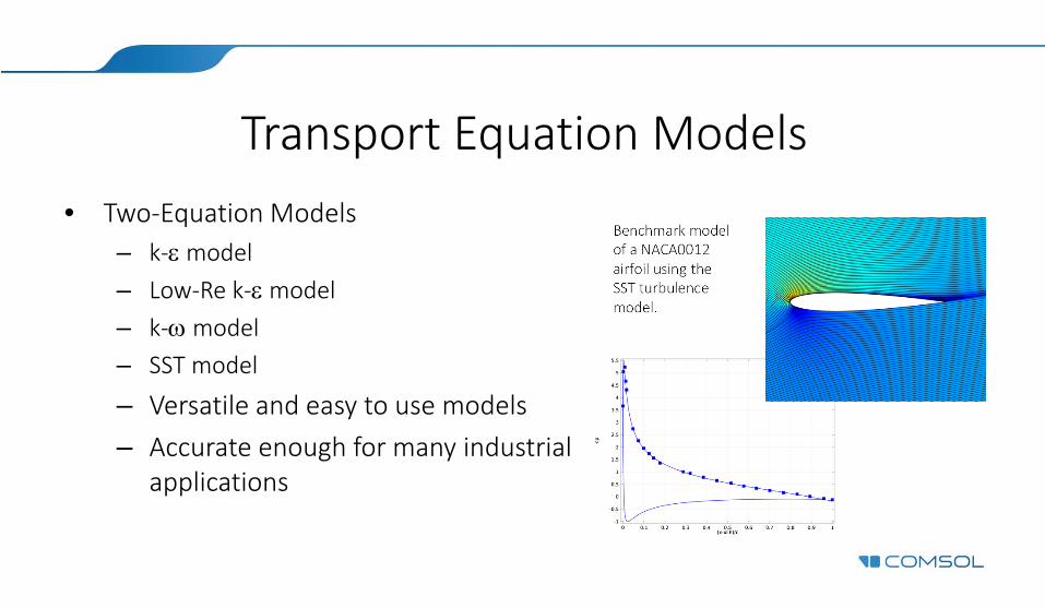
Transport Equation Models
Benchmark model of a NACA0012 airfoil using the SST turbulence model.
Benchmark model of a NACA0012 airfoil using the SST turbulence model.
• Two‐Equation Models– k‐model– Low‐Re k‐model– k‐model– SST model
– Versatile and easy to use models– Accurate enough for many industrial
applications
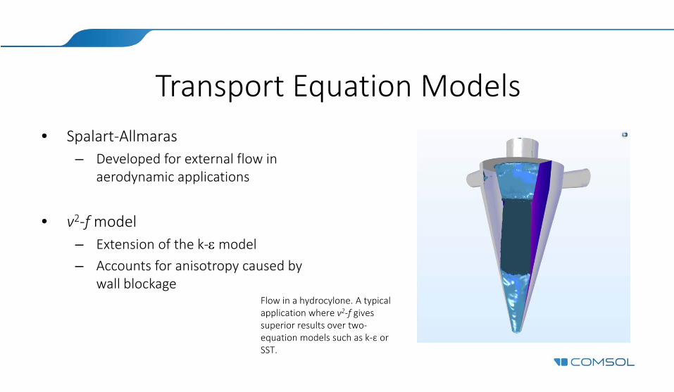
Transport Equation Models• Spalart‐Allmaras
– Developed for external flow in aerodynamic applications
• v2‐fmodel– Extension of the k‐model– Accounts for anisotropy caused by
wall blockageFlow in a hydrocylone. A typical application where v2‐f gives superior results over two‐equation models such as k‐ε or SST.
Flow in a hydrocylone. A typical application where v2‐f gives superior results over two‐equation models such as k‐ε or SST.
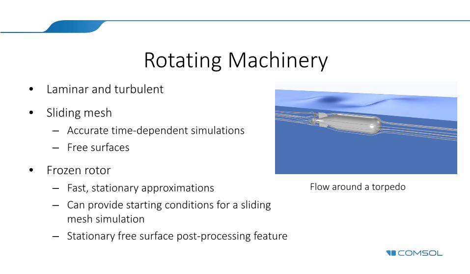
Rotating Machinery• Laminar and turbulent
• Sliding mesh– Accurate time‐dependent simulations– Free surfaces
• Frozen rotor– Fast, stationary approximations– Can provide starting conditions for a sliding
mesh simulation– Stationary free surface post‐processing feature
Flow around a torpedo Flow around a torpedo
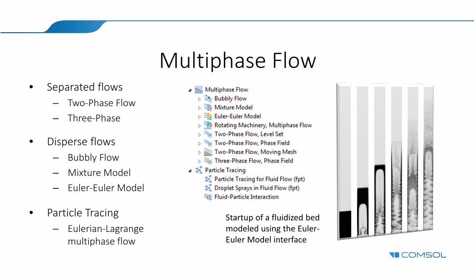
Multiphase Flow• Separated flows
– Two‐Phase Flow– Three‐Phase
• Disperse flows– Bubbly Flow– Mixture Model– Euler‐Euler Model
• Particle Tracing– Eulerian‐Lagrange
multiphase flow
Startup of a fluidized bed modeled using the Euler‐Euler Model interface
Startup of a fluidized bed modeled using the Euler‐Euler Model interface
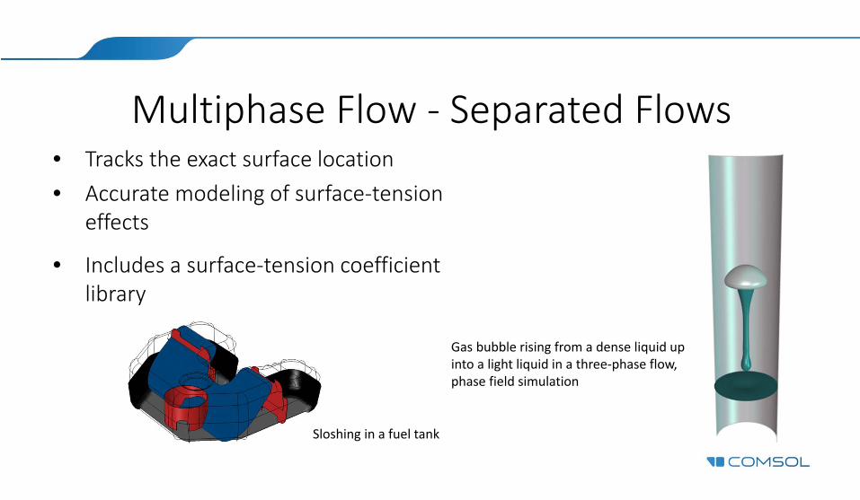
Multiphase Flow ‐ Separated Flows• Tracks the exact surface location• Accurate modeling of surface‐tension
effects
• Includes a surface‐tension coefficient library
Gas bubble rising from a dense liquid up into a light liquid in a three‐phase flow, phase field simulation
Gas bubble rising from a dense liquid up into a light liquid in a three‐phase flow, phase field simulation
Sloshing in a fuel tankSloshing in a fuel tank

Multiphase Flow – Disperse Flows• Bubbly Flow & Mixture Model
– Short particle relaxation time– For Bubbly flow, bubble concentration must be small (~0.1) – Bubble induced turbulence in bubbly flow– Mass transfer between phases– Option to solve for interfacial area
• Euler‐Euler Flow– General two‐phase flow– No restriction on particle relaxation time– Mixture or phase‐specific turbulence model
Bubble‐induced turbulent flow in an airlift loop reactorBubble‐induced turbulent flow in an airlift loop reactor
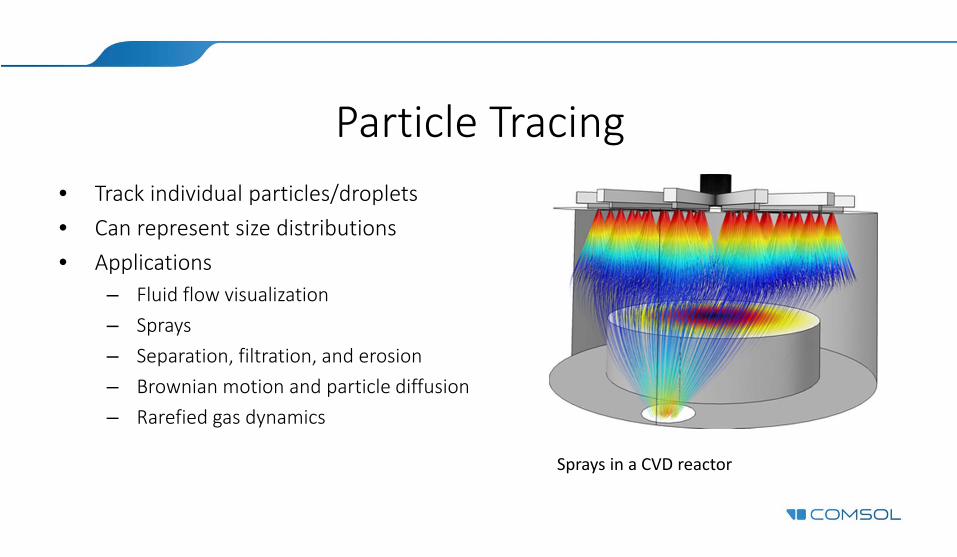
Particle Tracing• Track individual particles/droplets• Can represent size distributions• Applications
– Fluid flow visualization– Sprays– Separation, filtration, and erosion– Brownian motion and particle diffusion– Rarefied gas dynamics
Sprays in a CVD reactorSprays in a CVD reactor
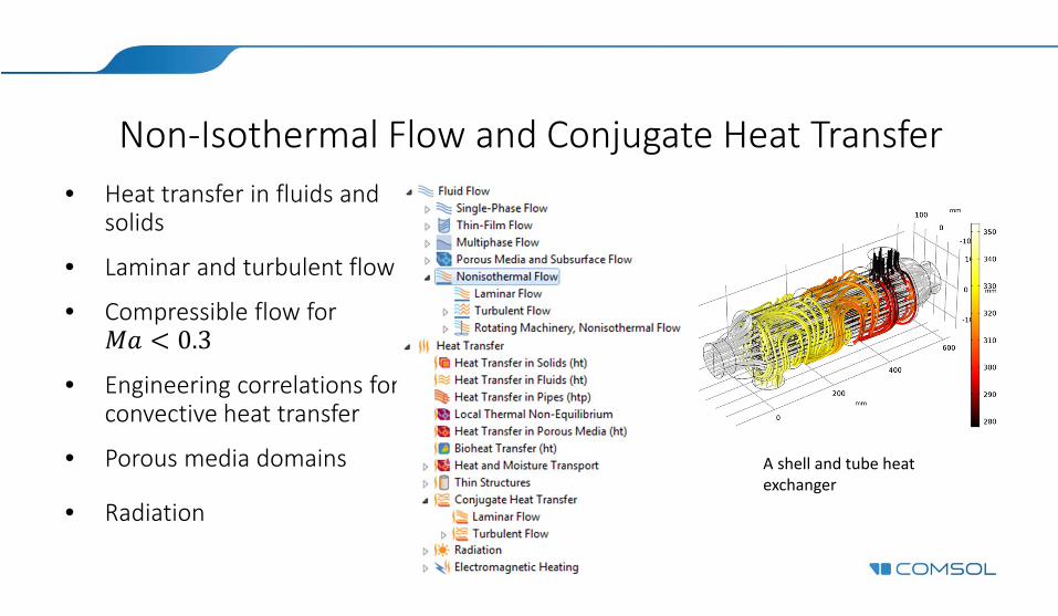
Non‐Isothermal Flow and Conjugate Heat Transfer • Heat transfer in fluids and
solids
• Laminar and turbulent flow
• Compressible flow for 0.3
• Engineering correlations for convective heat transfer
• Porous media domains
• Radiation
A shell and tube heat exchangerA shell and tube heat exchanger

High Mach Number Flow• Extension of Non‐Isothermal Flow
• Laminar and turbulent flow
• Fully compressible flow for all Mach numbers
Turbulent compressible flow in a two‐dimensional Sajben diffuserTurbulent compressible flow in a two‐dimensional Sajben diffuser
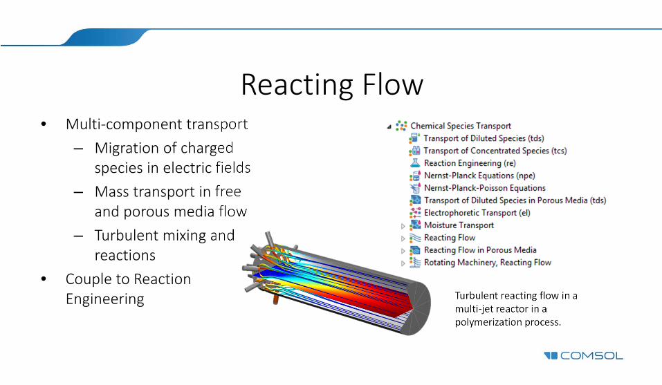
Reacting Flow• Multi‐component transport
– Migration of charged species in electric fields
– Mass transport in free and porous media flow
– Turbulent mixing and reactions
• Couple to Reaction Engineering Turbulent reacting flow in a
multi‐jet reactor in a polymerization process.
Turbulent reacting flow in a multi‐jet reactor in a polymerization process.
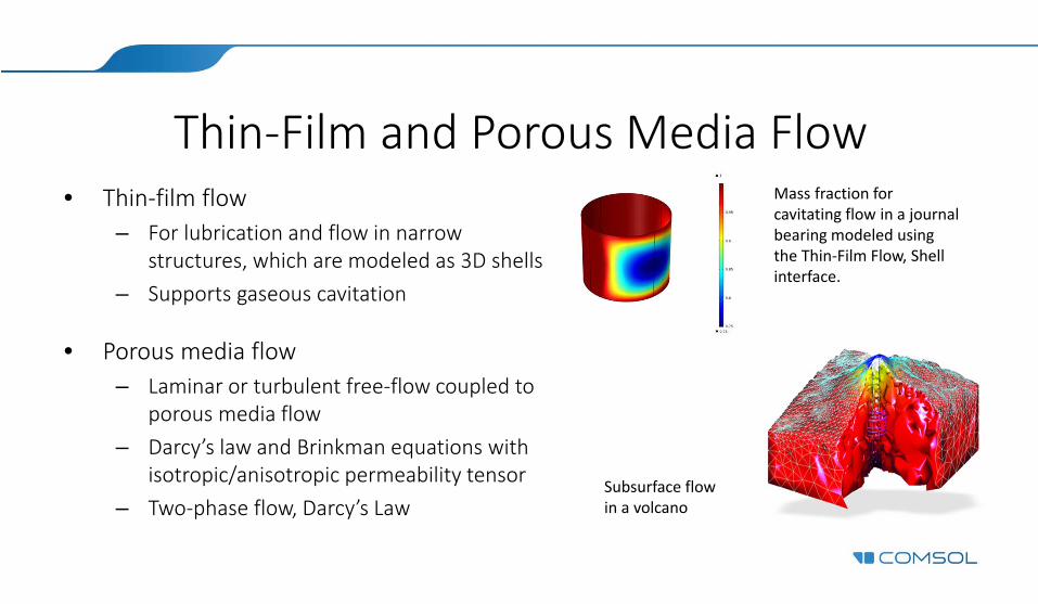
Thin‐Film and Porous Media Flow• Thin‐film flow
– For lubrication and flow in narrow structures, which are modeled as 3D shells
– Supports gaseous cavitation
• Porous media flow– Laminar or turbulent free‐flow coupled to
porous media flow – Darcy’s law and Brinkman equations with
isotropic/anisotropic permeability tensor– Two‐phase flow, Darcy’s Law
Subsurface flow in a volcanoSubsurface flow in a volcano
Mass fraction for cavitating flow in a journal bearing modeled using the Thin‐Film Flow, Shell interface.
Mass fraction for cavitating flow in a journal bearing modeled using the Thin‐Film Flow, Shell interface.
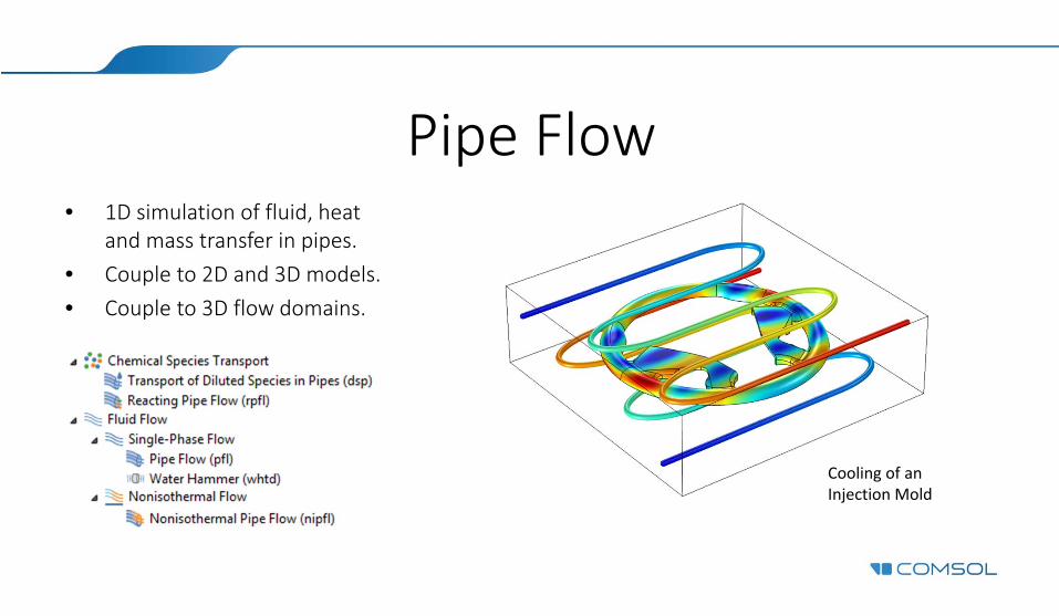
Pipe Flow• 1D simulation of fluid, heat
and mass transfer in pipes.• Couple to 2D and 3D models.• Couple to 3D flow domains.
Cooling of an Injection MoldCooling of an Injection Mold
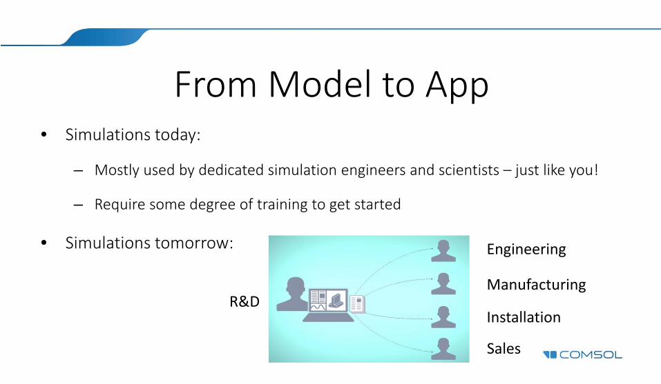
From Model to App• Simulations today:
– Mostly used by dedicated simulation engineers and scientists – just like you!
– Require some degree of training to get started
• Simulations tomorrow:
R&D
Engineering
Manufacturing
Installation
Sales
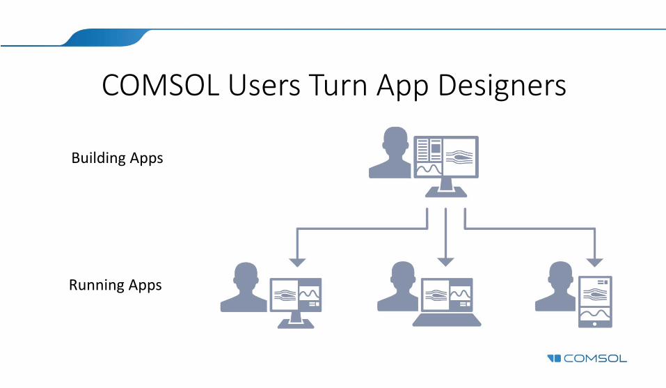
COMSOL Users Turn App Designers
Building Apps
Running Apps
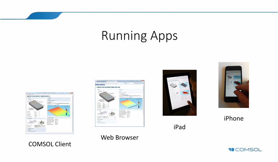
Running Apps
iPhoneiPad
Web BrowserCOMSOL Client
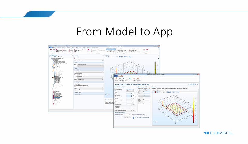
From Model to App