cfa guidance note: anchor terminology & notation · pdf fileindustry. from 2012 onward the...
TRANSCRIPT

CONSTRUCTION FIXINGS - TERMINOLOGY AND NOTATION Issue 1. July 2013 1
Ensuring best fixings practice www.fixingscfa.co.uk
CFA Guidance note: Anchor Terminology & Notation Contents I Introduction 2 CFA Policy 3 Scope 4 Terminology 4.1 Loads 4.1.1 Partial Safety Factor & Global Safety Factor approaches – diagram comparing terms. 4.2 Other terms 5 Notation 6 Anchor types 1. INTRODUCTION Over the years many different terms have been used by manufacturers in catalogues and technical handbooks by Approval Bodies in Approval documents and by national and European committees in standards. BS 8539:2012 Code of practice for the selection and installation of post-installed anchors in concrete and masonry1 adopts much of the terminology used in the ETA system together with some terminology developed by the Construction Fixings Association to clarify various aspects of anchor usage. There is therefore a clear need for a reference to explain the meanings of different terms and their relationship to different terms used in other documents. This Guidance Notes sets out to do just that. The key areas, from which the terminology referred to here has been drawn, are: Traditional usage within the industry European Technical Assessment /Approval system BS 8539:2012 CEN Eurocodes CEN Technical Specifications 1992-4 CFA Guidance Notes 2 CFA POLICY The CFA has traditionally used terminology that has been most widely accepted with the construction fixings industry. From 2012 onward the CFA has adopted a policy of using the terminology referred to in BS8539 in all its new publications and will transform existing publications to the new terminology as they are renewed. Some Full Members of the CFA use alternative terminology and notation. 3 SCOPE AND FORMAT 3.1 Scope Not only are Terms covered but the notation used in BS 8539 is listed and defined. The most common anchor types are also listed with the various names used for each. 3.2 Format As so many terms relate to loads, in one form or another, and this category of terms has the most alternative uses and attracts the most confusion, these terms are listed first and other terms after. Each term will be listed in alphabetical order, although for loads will be slit into sub-groups of Actions and Resistances with alphabetical listing within each sub-group.

CFA Guidance note: Anchor Terminology and Notation
Anchor terminology and notation July 2013 2
Terms used in BS 8539, and adopted by CFA for future publications will be highlighted in bold and accompanied by a definition taken from BS 8539 with a commentary in italics. Alternative terms will be shown, where relevant, in [square] brackets, and also listed alphabetically with just a reference to the main term with no definition. Also, in view of the confusion created by the transition from Global Safety Factor approach to Partial safety factor approach a diagram is included, see 4.1.1, which shows how the different terms used in the two approaches relate to each other. In the case of Notation although other designations used in other documents these are not referred to as they are so many and varied as to be impossible to cover meaningfully. 4 TERMINOLOGY Note: In the definitions below “F” implies a load in any direction, "N" implies a tensile load, “V” implies a shear load. 4.1 Loads actions
action [load], load (force) transferred into a base material by a fixture via an anchor
applied load – see characteristic action, unfactored load, working load
bending action, [bending load], action applied to an anchor with a lever arm
bending moment, result of an action applied to a fixture at a lever arm which can result in a tensile action being applied to an anchor
characteristic action, [applied load, unfactored load, working load1], action applied by a fixture to an anchor or group of anchors
characteristic permanent action [dead load] ,component of a characteristic action that is likely to act throughout the life of the structure, and for which the variation in magnitude with time is negligible
characteristic variable action [imposed load, live load], component of a characteristic action for which the variation in magnitude with time is neither negligible nor monotonic (i.e. in the same direction)
combined action [combined load], combination of tensile and shear actions applied simultaneously
dead load – see characteristic permanent action
design action, [factored load, design load?], action derived from the characteristic action by application of a partial safety factor for the action
factored load – see design action
imposed load – see characteristic variable action, live load
live load – see characteristic variable action, imposed load
non-static action, action which can be characterized by fatigue, seismic or shock actions
quasi-static action, variable action which is treated as being static
seismic action, action resulting from seismic activity (earthquakes) transmitted from the ground to the anchorage via the building structure
shock action, single action of high magnitude occurring over short duration (milliseconds)
static action, action comprising loads which are constant (permanent actions) and/or those which change only slowly (variable actions)
1 “Working load” is a scaffolding term used in TG20 published by NASC, & TG4 published by NASC & CFA.
CFA Guidance note: Anchor Terminology and Notation
Anchor terminology and notation July 2013 3
resistance (load) capacity of an anchorage to resist actions
allowable resistance, (tensile) [allowable load], maximum working load derived from tests carried out on site when the proposed anchor is to be used in a base material approved by the manufacturer but for which there is no recommended resistance (load)
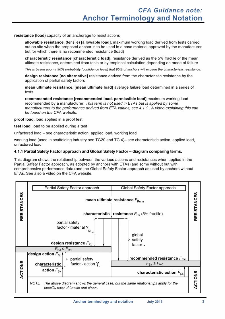
characteristic resistance [characteristic load], resistance derived as the 5% fractile of the mean ultimate resistance, determined from tests or by empirical calculation depending on mode of failure This is based upon a 90% probability (confidence level) that 95% of anchors will exceed the characteristic resistance.
design resistance [no alternative] resistance derived from the characteristic resistance by the application of partial safety factors
mean ultimate resistance, [mean ultimate load] average failure load determined in a series of tests
recommended resistance [recommended load, permissible load] maximum working load recommended by a manufacturer. This term is not used in ETAs but is applied by some manufacturers to the performance derived from ETA values, see 4.1.1 . A video explaining this can be found on the CFA website.
proof load, load applied in a proof test
test load, load to be applied during a test
unfactored load – see characteristic action, applied load, working load
working load (used in scaffolding industry see TG20 and TG 4)– see characteristic action, applied load, unfactored load
4.1.1 Partial Safety Factor approach and Global Safety Factor – diagram comparing terms. This diagram shows the relationship between the various actions and resistances when applied in the Partial Safety Factor approach, as adopted by anchors with ETAs (and some without but with comprehensive performance data) and the Global Safety Factor approach as used by anchors without ETAs. See also a video on the CFA website.

CFA Guidance note: Anchor Terminology and Notation
Anchor terminology and notation July 2013 4
4.2 Other terms anchor [fixing, fastener - CEN TS2] manufactured device for achieving a connection between a fixture and the base material
anchor group, two or more anchors used in combination to achieve a connection between a single fixture and the base material. This is not the same as multiple use.
anchorage [fastening - CEN TS2], assembly comprising a base material, an anchor or anchor group, and a fixture
base material, material of a structure into which an anchor is installed
base plate, part of a fixture forming the direct contact between an anchor or group of anchors and the base material
client, person who commissions or procures the carrying out of a project
competent, suitably trained and qualified by knowledge and practical experience, and provided with the necessary instructions, to enable the required task(s) to be carried out correctly
compression, direction of loading along the axis of an anchor toward the base material When used as an adjective, this is known as “compressive”.
concrete strength, compressive strength of the concrete base material into which an anchor is to be installed. This is derived from compression tests on cylinders/cubes, e.g. C20/25.
contractor, organization or employer whose employees undertake, carry out or manage construction work
construction stage, period of time starting when preparation of a construction site begins and ending when work on the project is completed
cracked concrete, concrete likely to be subjected to tension at any point in its lifetime Guidance on the determination of cracked concrete is given in ETAG 001, Annex C [5] and CEN/TS 1992-4-1.
creep, time-dependent phenomenon that results in an increase in initial deformation under constant load, which in turn could result in relaxation in a fixture. Anchors which suffer from creep might sustain significant loads under short-term test conditions but fail at significantly lower loads if applied over the long term.
design life, period for which an anchorage is intended to remain in use. This is normally 50 years for building structures.
designer, person with overall responsibility for the design of a structure, which includes the anchorage, throughout the whole design and construction stage. The designer might or might not be the specifier.
embedment depths
effective embedment depth, hef, depth from the surface of a load-bearing structure to the lowest point where an anchor engages with the base material
nominal embedment depth, hnom, depth from the surface of a load-bearing structure to the lowest part of an anchor
elevated temperature, temperature higher than the range of service temperatures normally considered
European Assessment Document, EAD, [European Technical Approval Guideline – ETAG] A harmonized Technical Specification which sets out the framework for the test and assessment of a construction product to facilitate the award of an ETA. See also3.
European Technical Assessment, ETA, [European Technical Approval] document providing information on the assessment of the performance of a construction product, in relation to its essential characteristics. See also3.
ETAG – see European Assessment Document (see also3)
2 CEN TS 1992 – 4 Parts 1 – 5 Design of fastening for use in concrete. Published by CEN. 3 CFA guidance Note: ETAs and design methods for construction products. CFA website
CFA Guidance note: Anchor Terminology and Notation
Anchor terminology and notation July 2013 5
fixture, component to be fixed to the base material
global safety factor approach, determination of recommended resistance by application of a single safety factor (ν) to either the characteristic or ultimate (mean average) resistance of an anchor
installer, person or organization trained in the process of installing anchors NOTE The installer is usually employed by a contractor.
lateral, direction of loading perpendicular to the axis of an anchor
manufacturer, person or organization who develops, manufactures, and supplies anchors
masonry, building element constructed from masonry units, such as bricks, blocks or stones
multiple use, particular application category where multiple anchors are employed to support an installation system, in which failure of a single anchor will not cause collapse of the whole supported structure An application qualifies as multiple use if the number (n1) of fixing points, the number (n2) of anchors per fixing point
and the value of the design action, NSd (n3) are as follows: for ETAG 001, Part 6: either n1 ≥ 4; n2 ≥ 1 and n3 ≤ 3.0 kN; or n1 ≥ 3; n2 ≥ 1 and n3 ≤ 2.0 kN; for ETAG 020: either n1 ≥ 4; n2 ≥1 and n3 ≤ 4.5 kN; or n1 ≥ 3;n2 ≥ 1and n3 ≤ 3.0 kN. Examples include suspended ceilings or runs of mechanical/electrical containment. This is not the same as reuse.
non-cracked concrete, concrete unlikely to be subjected to tension at any point in its lifetime. Guidance on the determination of non-cracked concrete is given in ETAG 001, Annex C and CEN/TS 1992-4 Part 1.
partial safety factor approach, application of partial factors of safety to characteristic actions and resistances to determine the respective design values, in order to verify that no relevant limit state is exceeded
partial safety factor for action, partial safety factor applied to the characteristic action to derive the design action
partial safety factor for material, partial safety actor applied to the characteristic resistance to determine the design resistance
preliminary test, test carried out on site to determine the allowable resistance in the case where no characteristic resistance or recommended resistance is available. Also known as “test for allowable resistance (simplified approach)”; see BS 8539 Annex B.2.3.1. and CFA Guidance Note: Procedure for site testing construction fixings -2012.
progressive collapse, sequential spread of local damage from an initiating event, from element to element, resulting in the collapse of a number of elements
proof tests, tests carried out on a proportion of anchors to validate correct installation
redundancy, situation where there are more load paths than strictly necessary to carry the load through the structure, or part thereof
robustness, ability of a structure/structural system to accept a certain amount of damage without that structure failing to any degree. Robustness implies insensitivity to local failure.
safety-critical application, application in which the failure of anchors can:
a) result in collapse or partial collapse of the structure; and/or
b) cause risk to human life; and/or
c) lead to significant economic loss This definition is adapted from ETAG 001, Part 1.
selection, overall process of selecting the type and size of an anchor or group of anchors The process of design of the anchor will be one part of this process.

CFA Guidance note: Anchor Terminology and Notation
Anchor terminology and notation July 2013 6
shear, lateral loading that can be coincident with the face of a base material or applied at a lever arm. Where used to describe anchor performance, “shear” is taken to mean coincident with the face of the base material.
specification, complete reference of an anchor in sufficient detail to facilitate its supply and installation
specifier, person or organization responsible for the selection (including anchor design) and specification of an anchor. The specifier might or might not be the designer.
statically determinate, application in which the stability of a fixture is dependent on every anchor supporting it
statically indeterminate, application in which stability of a fixture is not dependent on every anchor supporting it, i.e. there is a degree of redundancy
supplier, person or organization that supplies anchors
supervisor, person who supervises the installer, usually employed by the contractor
tension, direction of loading along the axis of an anchor and tending to pull the anchor out of the base material. When used as an adjective, this is known as “tensile”.
tester, person or organization that tests anchors on site
5 Notation The following symbols apply in BS 8539 and will be adopted, as far as possible, within CFA publications. α factor used in checking the compatibility of design actions compared with design resistances in the
case of combined actions ccr characteristic edge distance, at which full performance may be used. Previously referred to as “critical
edge distance”, same notation. cmin minimum edge distance, at which performance has to be reduced according to manufacturer’s data d0 nominal diameter of drill bit F action or resistance with direction unspecified FR,all allowable resistance FRd design resistance FRk characteristic resistance FRu,m mean ultimate resistance from a series FSd design action FSk characteristic action Frec recommended resistance fck,cube concrete compressive strength (cube) fck,cylinder concrete compressive strength (cylinder) Gk characteristic permanent action h thickness of base material h0 depth of cylindrical drilled hole with full diameter h1 depth of drilled hole to deepest point hef effective embedment depth from the surface of the load-bearing structure hnom nominal embedment depth of the anchor from the surface of the load-bearing structure K special factor that adjusts the width of the tolerance interval to account for uncertainty In BS 8539 the
K factor is taken from standard statistical tables, to give a 90% probability (confidence level) that 95% will exceed the calculated characteristic resistance.
MRd design bending moment N tensile actions or resistances Note: All actions and resistances shown beginning N, to denote tensile actions or resistances, and listed below, can be
converted to the equivalent for shear actions or resistances by replacing N with V. N1st load at first movement in a test N1st,m mean load at first movement in a test series Np tensile load applied in a proof load test NR,all allowable tensile resistance
CFA Guidance note: Anchor Terminology and Notation
Anchor terminology and notation July 2013 7
NRd design tensile resistance NRk characteristic tensile resistance NRk,ETA characteristic tensile resistance quoted in an ETA for this category of base material NRk1
characteristic tensile resistance for a specific base material in a test NRu ultimate tensile resistance recorded in a single test NRu,m mean ultimate tensile resistance from a series of tests Nrec recommended tensile resistance NSd design tensile action NSk characteristic tensile action Ntest tensile test load applied in preliminary tests Nu,ave average tensile load recorded in preliminary tests Nu,low lowest tensile load recorded in preliminary tests n0 number of anchors originally required in a test n′ new number of anchors required with the allowable resistance derived from a test n1 number of fixing points n2 number of anchors per fixing point n3 limiting value of design action on a fixing point for multiple use Qk characteristic variable action scr characteristic spacing, at which full performance may be used Previously referred to as “critical spacing”, same notation. smin minimum spacing, at which performance has to be reduced according to manufacturer’s data s standard deviation of failure loads about the mean Tinst manufacturer’s recommended installation torque V shear actions or resistances All actions and resistances shown beginning N, to denote tensile actions or resistances, can be converted to the
equivalent for shear actions or resistances by replacing N with V. v coefficient of variation of the ultimate load in a test series β influencing factor used in determining results of site tests The values of this factor are given in the relevant approval document for the anchor. βN ratio of design tensile action to design tensile resistance βV ratio of design shear action to design shear resistance δNO tensile displacement, short-term δN∞ tensile displacement, long-term δVO shear displacement, short-term δV∞ shear displacement, long-term γF partial safety factor γG partial safety factor γM partial safety factor γMc partial safety factor γMp partial safety factor γMsp partial safety factor γMs partial safety factor γQ partial safety factor ν global safety factor νave factor used in determining allowable resistance, from average test result νlow factor used in determining allowable resistance, from lowest test result νP,test factor for determining proof test loads νtest factor used in preliminary tests to determine Ntest
Ω adjustment factor for site conditions
CFA Guidance note: Anchor Terminology and Notation
Anchor terminology and notation July 2013 8
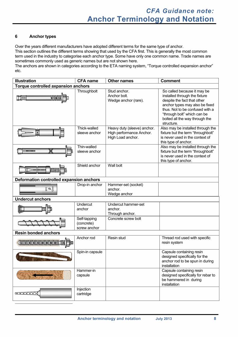
6 Anchor types Over the years different manufacturers have adopted different terms for the same type of anchor. This section outlines the different terms showing that used by the CFA first. This is generally the most common term used in the industry to categorise each anchor type. Some have only one common name. Trade names are sometimes commonly used as generic names but are not shown here. The anchors are shown in categories according to the ETA naming system, “Torque controlled expansion anchor” etc. Illustration CFA name Other names Comment Torque controlled axpansion anchors
Throughbolt Stud anchor. Anchor bolt. Wedge anchor (rare).
So called because it may be installed through the fixture despite the fact that other anchor types may also be fixed thus. Not to be confused with a “through bolt” which can be bolted all the way through the structure.
Thick-walled sleeve anchor
Heavy duty (sleeve) anchor. High performance Anchor. High Load anchor.
Also may be installed through the fixture but the term “throughbolt” is never used in the context of this type of anchor.
Thin-walled sleeve anchor
Also may be installed through the fixture but the term “throughbolt” is never used in the context of this type of anchor.
Shield anchor Wall bolt
Deformation controlled expansion anchors Drop-in anchor Hammer-set (socket)
anchor. Wedge anchor
Undercut anchors
Undercut anchor
Undercut hammer-set anchor. Through anchor.
Self-tapping (concrete) screw anchor
Concrete screw bolt
Resin bonded anchors
Anchor rod
Resin stud Thread rod used with specific resin system
Spin-in capsule Capsule containing resin designed specifically for the anchor rod to be spun in during installation
Hammer-in capsule
Capsule containing resin designed specifically for rebar to be hammered in during installation
Injection cartridge
M10
O
12m
m