certification of composite- metal hybrid structures of composite- metal hybrid structures damage...
TRANSCRIPT
Certification of Composite-Metal Hybrid Structures Damage Tolerance Testing and Analysis Protocols for Full-Scale Composite Airframe Structures under Repeated Loading
2013 Technical Review Waruna Seneviratne & John Tomblin Wichita State University/NIAR
2
Certification of Composite-Metal Hybrid Structures
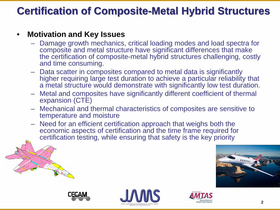
• Motivation and Key Issues – Damage growth mechanics, critical loading modes and load spectra for
composite and metal structure have significant differences that make the certification of composite-metal hybrid structures challenging, costly and time consuming.
– Data scatter in composites compared to metal data is significantly higher requiring large test duration to achieve a particular reliability that a metal structure would demonstrate with significantly low test duration.
– Metal and composites have significantly different coefficient of thermal expansion (CTE)
– Mechanical and thermal characteristics of composites are sensitive to temperature and moisture
– Need for an efficient certification approach that weighs both the economic aspects of certification and the time frame required for certification testing, while ensuring that safety is the key priority
3
Certification of Composite-Metal Hybrid Structures
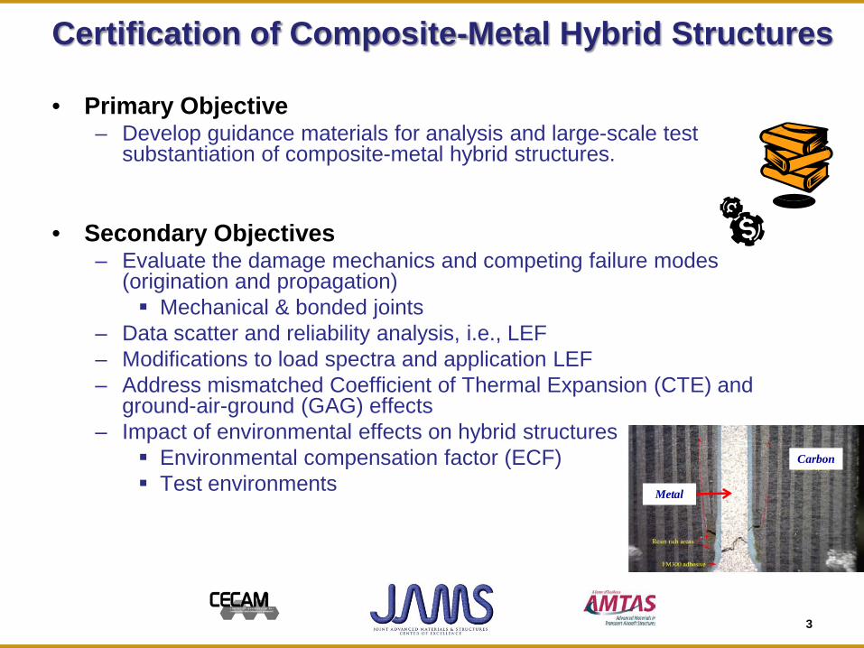
• Primary Objective – Develop guidance materials for analysis and large-scale test
substantiation of composite-metal hybrid structures.
• Secondary Objectives – Evaluate the damage mechanics and competing failure modes
(origination and propagation) Mechanical & bonded joints
– Data scatter and reliability analysis, i.e., LEF – Modifications to load spectra and application LEF – Address mismatched Coefficient of Thermal Expansion (CTE) and
ground-air-ground (GAG) effects – Impact of environmental effects on hybrid structures
Environmental compensation factor (ECF) Test environments
Carbon
Metal
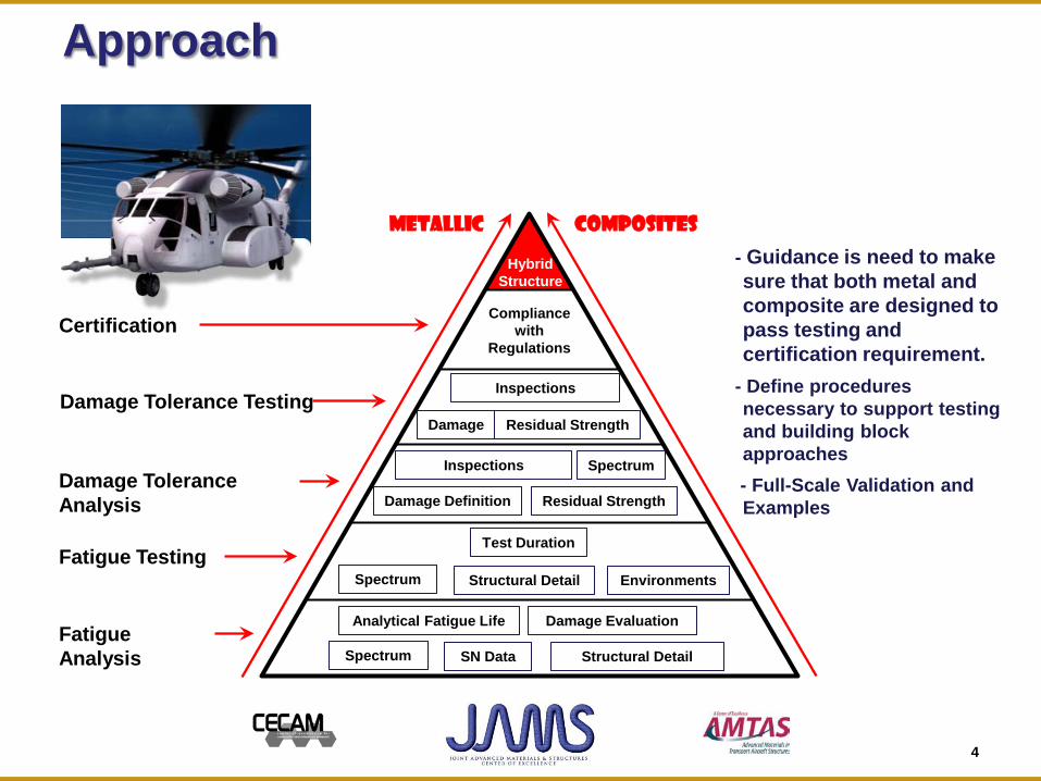
Approach
Analytical Fatigue Life Damage Evaluation
Spectrum SN Data Structural Detail
Test Duration
Spectrum Structural Detail Environments
Fatigue Analysis
Fatigue Testing
Damage Tolerance Analysis
Damage Tolerance Testing
Certification
Metallic COMPOSITES
Inspections Spectrum
Damage Definition Residual Strength
Inspections
Damage
Compliance with
Regulations
Hybrid Structure
Residual Strength
- Guidance is need to make sure that both metal and composite are designed to pass testing and certification requirement.
- Define procedures necessary to support testing and building block approaches
- Full-Scale Validation and Examples
4
5
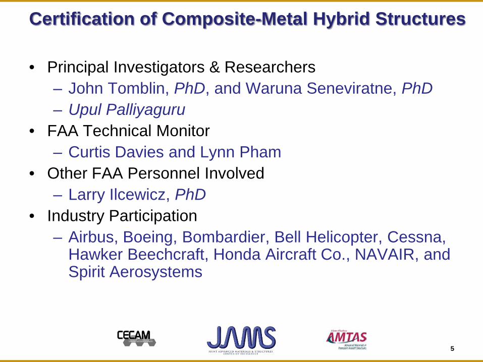
Certification of Composite-Metal Hybrid Structures
• Principal Investigators & Researchers – John Tomblin, PhD, and Waruna Seneviratne, PhD – Upul Palliyaguru
• FAA Technical Monitor – Curtis Davies and Lynn Pham
• Other FAA Personnel Involved – Larry Ilcewicz, PhD
• Industry Participation – Airbus, Boeing, Bombardier, Bell Helicopter, Cessna,
Hawker Beechcraft, Honda Aircraft Co., NAVAIR, and Spirit Aerosystems
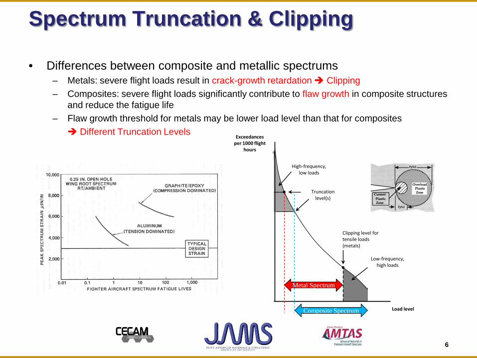
Spectrum Truncation & Clipping
• Differences between composite and metallic spectrums – Metals: severe flight loads result in crack-growth retardation Clipping – Composites: severe flight loads significantly contribute to flaw growth in composite structures
and reduce the fatigue life – Flaw growth threshold for metals may be lower load level than that for composites Different Truncation Levels
Metal Spectrum
Exceedances per 1000 flight
hours
Load level
Truncation level(s)
High-frequency, low loads
Clipping level for tensile loads (metals)
Clipping level for compressive
loads (metals)
Low-frequency, high loads Low-frequency, high
compressive loads
Composite Spectrum
6
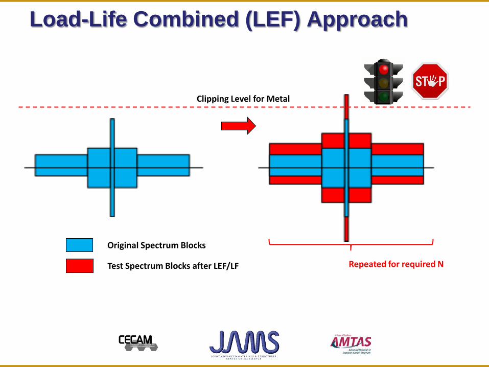
Load-Life Combined (LEF) Approach
Clipping Level for Metal
Original Spectrum Blocks
Test Spectrum Blocks after LEF/LF Repeated for required N
Clipping Level for Metal
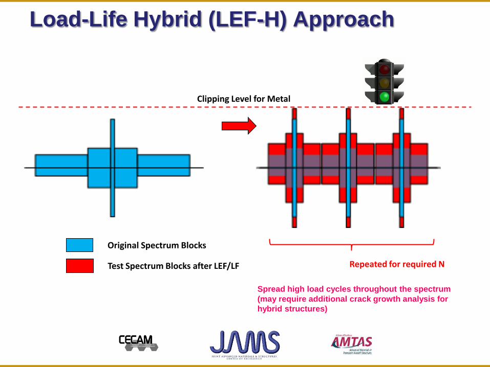
Load-Life Hybrid (LEF-H) Approach
Original Spectrum Blocks
Test Spectrum Blocks after LEF/LF Repeated for required N
Spread high load cycles throughout the spectrum (may require additional crack growth analysis for hybrid structures)
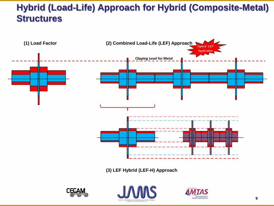
Hybrid (Load-Life) Approach for Hybrid (Composite-Metal) Structures
(1) Load Factor (2) Combined Load-Life (LEF) Approach
(3) LEF Hybrid (LEF-H) Approach
Clipping Level for Metal
Typical LEF Application
9
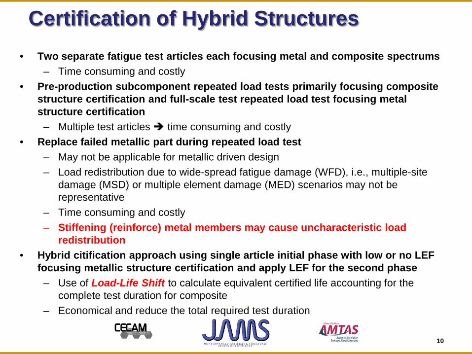
Certification of Hybrid Structures • Two separate fatigue test articles each focusing metal and composite spectrums
– Time consuming and costly • Pre-production subcomponent repeated load tests primarily focusing composite
structure certification and full-scale test repeated load test focusing metal structure certification
– Multiple test articles time consuming and costly • Replace failed metallic part during repeated load test
– May not be applicable for metallic driven design – Load redistribution due to wide-spread fatigue damage (WFD), i.e., multiple-site
damage (MSD) or multiple element damage (MED) scenarios may not be representative
– Time consuming and costly – Stiffening (reinforce) metal members may cause uncharacteristic load
redistribution • Hybrid citification approach using single article initial phase with low or no LEF
focusing metallic structure certification and apply LEF for the second phase – Use of Load-Life Shift to calculate equivalent certified life accounting for the
complete test duration for composite – Economical and reduce the total required test duration
10
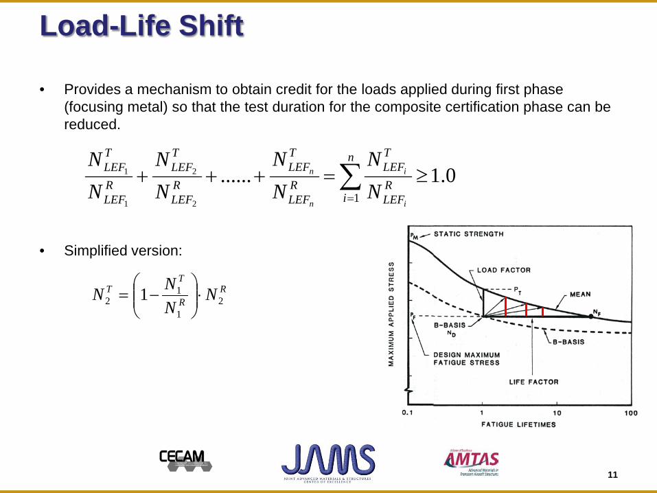
Load-Life Shift
• Provides a mechanism to obtain credit for the loads applied during first phase (focusing metal) so that the test duration for the composite certification phase can be reduced.
• Simplified version:
11
∑=
≥=+++n
iRLEF
TLEF
RLEF
TLEF
RLEF
TLEF
RLEF
TLEF
i
i
n
n
NN
NN
NN
NN
10.1......
2
2
1
1
R
R
TT N
NNN 2
1
12 1 ⋅
−=
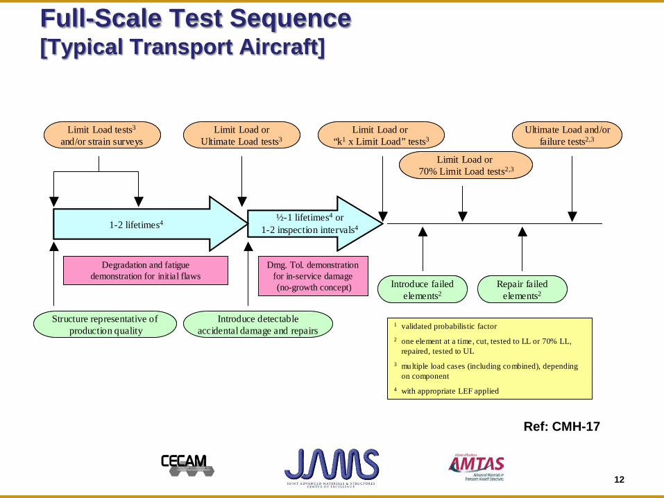
Full-Scale Test Sequence [Typical Transport Aircraft]
Limit Load or Ultimate Load tests3
Ultimate Load and/or failure tests2,3
Structure representative ofproduction quality
Introduce detectableaccidental damage and repairs
Dmg. Tol. demonstration for in-service damage(no-growth concept)
Degradation and fatigue demonstration for initial flaws
1 validated probabilistic factor2 one element at a time, cut, tested to LL or 70% LL,
repaired, tested to UL3 multiple load cases (including combined), depending
on component4 with appropriate LEF applied
½-1 lifetimes4 or1-2 inspection intervals41-2 lifetimes4
Limit Load or “k1 x Limit Load” tests3
Introduce failed elements2
Repair failed elements2
Limit Load or 70% Limit Load tests2,3
Limit Load tests3
and/or strain surveysLimit Load or
Ultimate Load tests3Ultimate Load and/or
failure tests2,3
Structure representative ofproduction quality
Introduce detectableaccidental damage and repairs
Dmg. Tol. demonstration for in-service damage(no-growth concept)
Degradation and fatigue demonstration for initial flaws
1 validated probabilistic factor2 one element at a time, cut, tested to LL or 70% LL,
repaired, tested to UL3 multiple load cases (including combined), depending
on component4 with appropriate LEF applied
½-1 lifetimes4 or1-2 inspection intervals4
½-1 lifetimes4 or1-2 inspection intervals41-2 lifetimes41-2 lifetimes4
Limit Load or “k1 x Limit Load” tests3
Introduce failed elements2
Repair failed elements2
Limit Load or 70% Limit Load tests2,3
Limit Load tests3
and/or strain surveys
12
Ref: CMH-17
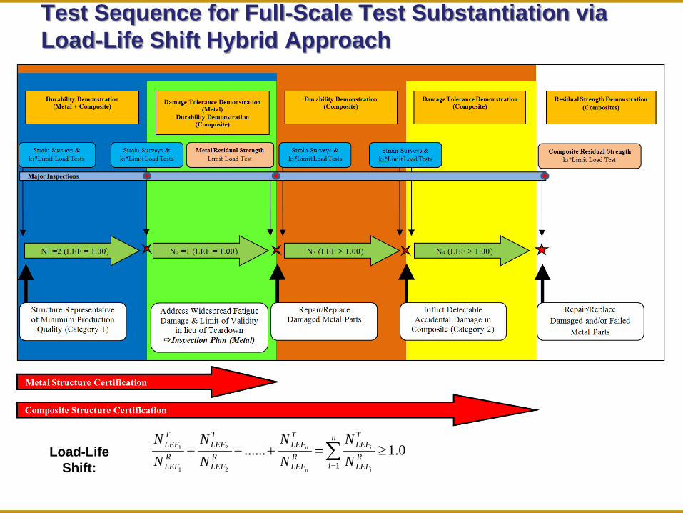
Test Sequence for Full-Scale Test Substantiation via Load-Life Shift Hybrid Approach
∑=
≥=+++n
iRLEF
TLEF
RLEF
TLEF
RLEF
TLEF
RLEF
TLEF
i
i
n
n
NN
NN
NN
NN
10.1......
2
2
1
1Load-Life Shift:
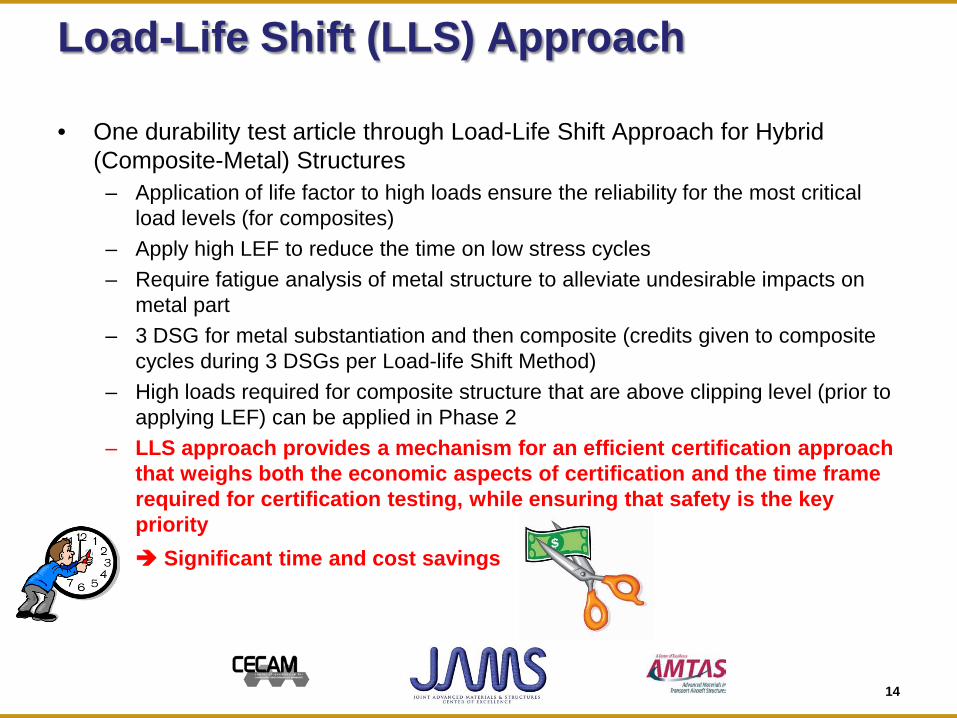
Load-Life Shift (LLS) Approach
• One durability test article through Load-Life Shift Approach for Hybrid (Composite-Metal) Structures
– Application of life factor to high loads ensure the reliability for the most critical load levels (for composites)
– Apply high LEF to reduce the time on low stress cycles – Require fatigue analysis of metal structure to alleviate undesirable impacts on
metal part – 3 DSG for metal substantiation and then composite (credits given to composite
cycles during 3 DSGs per Load-life Shift Method) – High loads required for composite structure that are above clipping level (prior to
applying LEF) can be applied in Phase 2 – LLS approach provides a mechanism for an efficient certification approach
that weighs both the economic aspects of certification and the time frame required for certification testing, while ensuring that safety is the key priority
Significant time and cost savings
14
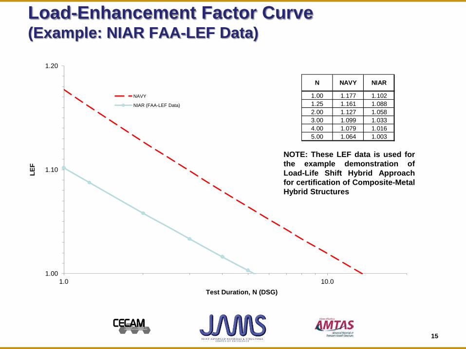
Load-Enhancement Factor Curve (Example: NIAR FAA-LEF Data)
1.00
1.10
1.20
1.0 10.0
LEF
Test Duration, N (DSG)
NAVY
NIAR (FAA-LEF Data)
1.00 1.177 1.1021.25 1.161 1.0882.00 1.127 1.0583.00 1.099 1.0334.00 1.079 1.0165.00 1.064 1.003
N NAVY NIAR
NOTE: These LEF data is used for the example demonstration of Load-Life Shift Hybrid Approach for certification of Composite-Metal Hybrid Structures
15
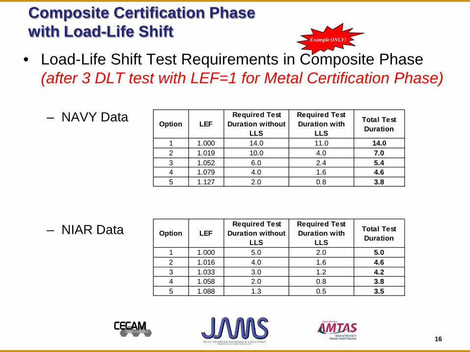
Composite Certification Phase with Load-Life Shift
• Load-Life Shift Test Requirements in Composite Phase (after 3 DLT test with LEF=1 for Metal Certification Phase)
– NAVY Data
– NIAR Data
Option LEF Required Test
Duration without LLS
Required Test Duration with
LLS
Total Test Duration
1 1.000 14.0 11.0 14.02 1.019 10.0 4.0 7.03 1.052 6.0 2.4 5.44 1.079 4.0 1.6 4.65 1.127 2.0 0.8 3.8
Option LEF Required Test
Duration without LLS
Required Test Duration with
LLS
Total Test Duration
1 1.000 5.0 2.0 5.02 1.016 4.0 1.6 4.63 1.033 3.0 1.2 4.24 1.058 2.0 0.8 3.85 1.088 1.3 0.5 3.5
Example ONLY!
16
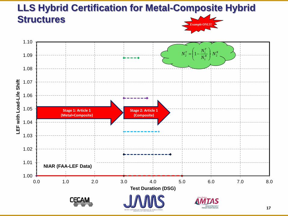
LLS Hybrid Certification for Metal-Composite Hybrid Structures
1.00
1.01
1.02
1.03
1.04
1.05
1.06
1.07
1.08
1.09
1.10
0.0 1.0 2.0 3.0 4.0 5.0 6.0 7.0 8.0
LEF
with
Loa
d-Li
fe S
hift
Test Duration (DSG)
Stage 2: Article 1 (Composite)
Stage 1: Article 1 (Metal+Composite)
NIAR (FAA-LEF Data)
Example ONLY!
17
RR
TT N
NNN 2
1
12 1 ⋅
−=
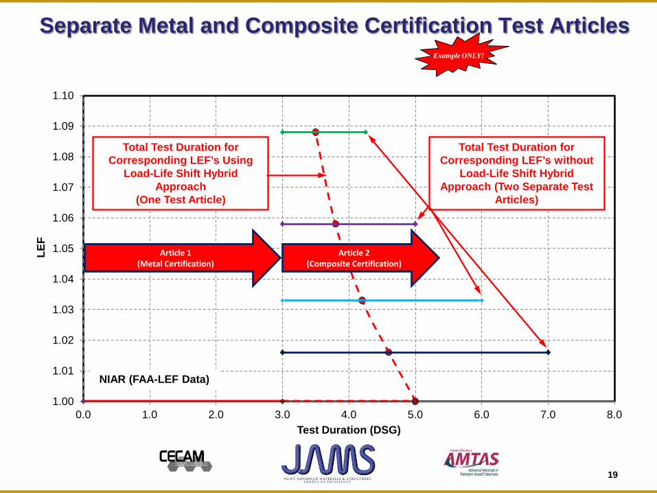
Separate Metal and Composite Certification Test Articles
1.00
1.01
1.02
1.03
1.04
1.05
1.06
1.07
1.08
1.09
1.10
0.0 1.0 2.0 3.0 4.0 5.0 6.0 7.0 8.0
LEF
Test Duration (DSG)
Article 2 (Composite Certification)
Article 1 (Metal Certification)
Total Test Duration for Corresponding LEF’s Using
Load-Life Shift Hybrid Approach
(One Test Article)
Total Test Duration for Corresponding LEF’s without
Load-Life Shift Hybrid Approach (Two Separate Test
Articles)
NIAR (FAA-LEF Data)
Example ONLY!
19
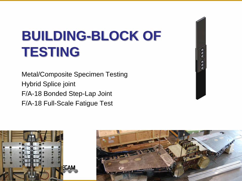
BUILDING-BLOCK OF TESTING Metal/Composite Specimen Testing Hybrid Splice joint F/A-18 Bonded Step-Lap Joint F/A-18 Full-Scale Fatigue Test
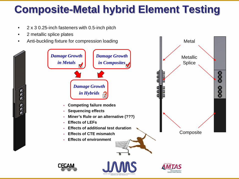
Composite-Metal hybrid Element Testing • 2 x 3 0.25-inch fasteners with 0.5-inch pitch • 2 metallic splice plates • Anti-buckling fixture for compression loading Metal
Composite
Metallic Splice
Damage Growth in Metals
Damage Growth in Composites
Damage Growth in Hybrids
• Competing failure modes • Sequencing effects • Miner’s Rule or an alternative (???) • Effects of LEFs • Effects of additional test duration • Effects of CTE mismatch • Effects of environment
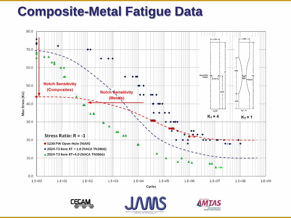
Composite-Metal Fatigue Data
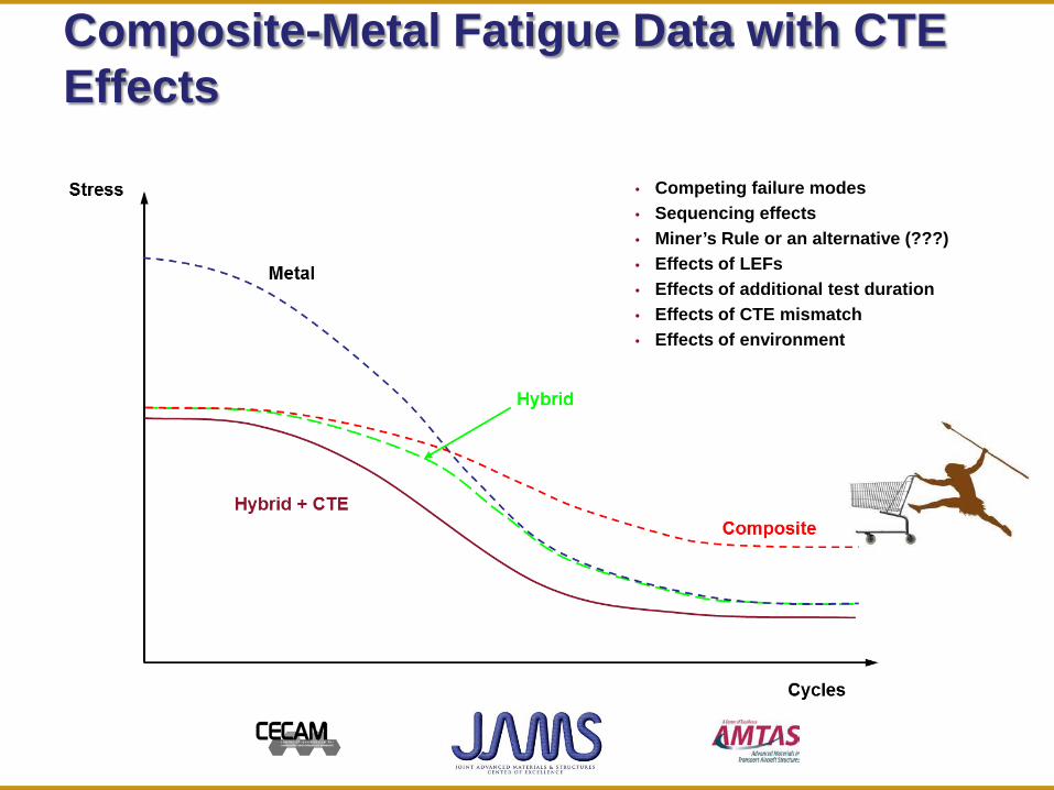
Composite-Metal Fatigue Data with CTE Effects
• Competing failure modes • Sequencing effects • Miner’s Rule or an alternative (???) • Effects of LEFs • Effects of additional test duration • Effects of CTE mismatch • Effects of environment
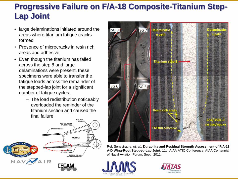
Progressive Failure on F/A-18 Composite-Titanium Step-Lap Joint • large delaminations initiated around the
areas where titanium fatigue cracks formed
• Presence of microcracks in resin rich areas and adhesive
• Even though the titanium has failed across the step 8 and large delaminations were present, these specimens were able to transfer the fatigue loads across the remainder of the stepped-lap joint for a significant number of fatigue cycles.
– The load redistribution noticeably overloaded the reminder of the titanium section and caused the final failure.
Ref: Seneviratne, et. al., Durability and Residual Strength Assessment of F/A-18 A-D Wing-Root Stepped-Lap Joint, 11th AIAA ATIO Conference, AIAA Centennial of Naval Aviation Forum, Sept., 2011.
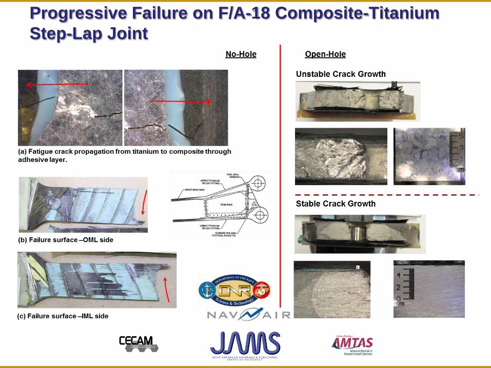
Progressive Failure on F/A-18 Composite-Titanium Step-Lap Joint

Full-Scale F/A-18 Inner-Wing Test Article Description
NAVAIR Public Release SPR-11-455: Distribution Statement A - "Approved for public release; distribution is unlimited"
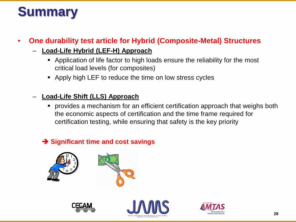
Summary
• One durability test article for Hybrid (Composite-Metal) Structures – Load-Life Hybrid (LEF-H) Approach
Application of life factor to high loads ensure the reliability for the most critical load levels (for composites)
Apply high LEF to reduce the time on low stress cycles
– Load-Life Shift (LLS) Approach provides a mechanism for an efficient certification approach that weighs both
the economic aspects of certification and the time frame required for certification testing, while ensuring that safety is the key priority
Significant time and cost savings
28
29
Looking Forward
• Benefit to Aviation – Efficient certification approach that weighs both the economic
aspects of certification and the time frame required for certification testing, while ensuring that safety is the key priority. Guidance materials for analysis and large-scale test substantiation of
composite-metal hybrid structures. Damage mechanics and competing failure modes (origination and
propagation) Guidance for hybrid load spectra and application LEF
• Future needs
– Representative test articles – Guidance on spectrum development
Notes
• Contact (Waruna Seneviratne): – [email protected] – Ph: 316-978-5221
• References:
– Tomblin, J and Seneviratne, W., Determining the Fatigue Life of Composite Aircraft Structures Using Life and Load-Enhancement Factors, DOT/FAA/AR-10/06, Federal Aviation Administration, National Technical Information Service, Springfield, VA, 2010.
– Tomblin, J and Seneviratne, W., Durability and Damage Tolerance Testing of Starship Forward Wing with Large Damages, DOT/FAA/AR-11/XX, Federal Aviation Administration, National Technical Information Service, Springfield, VA, 2013.
– Whitehead, R. S., Kan, H. P., Cordero, R., and Seather, E. S., Certification Testing Methodology for Composite Structures, Report No. NADC-87042-60, Volumes I and II, October, 1986.
30
End of Presentation.
Thank you.
31