certificate of ,$ffi1f,ttlljffif*, form qlffi iunnnnrl,trur
TRANSCRIPT

CERTIFICATE OF APPROPRIAAPPLICATIO
TENESS ,$ffi1f,ttllJffif*,N FORM qlffi
iunnnnrl,trurPROPERTY
Adoress 1040
Historic District / Landmark NOrhill HistoriC DistriCt HCAD # 0621120000030
subdivision North Norhill Lot 10 Block 133
DESIGNATION TYPEE Landmark
! Protected Landmark
I Archaeologicalsite
OWNER
*ur" Bruce Boatner
E Contributing
! Noncontributing
I Vacant
PROPOSED ACTION[l Ateration or Addition f] Retocation
fl Restoration E Dernolition
n New Construction ! Excavation
DOCUMENTS
K] Application checklist for each proposed action and all applicable documentation listed within are attached
APPLICANT 1ir other than owner)
ruameCarrie Gonzales
Company
Maiting Addres" 1040 Key Street
companv Richard Grothues Designs, lncrr,rairingeoaress 10810 Katy Frwy Suite 204
Houston Tx77043Houston TX 77009
Phone 713.385.4986 Pnone832.226.4232
emair
-Dsig"ature D-au<-,R#o,t" 9f >'r'rACKNOWLEDGEMENT OF RESPONSIBILITYRequirements: A complete application includes all applicable information requested on checklists to provide a completeand accurate description of existing and proposed conditions. Preliminary review meeting or site visii with staff may benecessary to process the application. owner contact information and signature is required. Late or incompleteapplications will not be considered.Deed Restrictions: You have verified that the work does not violate applicable deed restrictions.Public Records: lf attached materials are protected by copyright law, you grant the City of Houston, its officers, agencies,departments, and employees, non-exclusive rights to repiooJce, oistrioutJ and publish copyrighted materials before theHouston Archaeological and Historical Commiision, the Planning Commission, City Council, and other City of Houstoncommissions, agencies, and departments, on a City of Houston website, or oth-er public forum for the purposes ofapplication for a Certificate of Appropriateness or buiioing permit, and other educational and not for profit purposes. youhereby represent that you possess the requisite permissioin'or rights being conveyed here to the City.Gompliance: lf granted, you agree to comply with all conditions of the CoA. Revisions to approved work require staffreview and may require a new application and HAHC approval. Failure to comply with the CoA may result in projectdelays, fines or other penalties.
Emait
Rev. 02.2015
Application reeeived: _/_/_ Application complete: _/_/_

CERTIFICATE OF APPROPRIATENESS APPLICATION INSTRUCTIONS
Well in advance of the COA application deadline contact staff to discuss your project, application requirements, and, if necessary, to make an appointment to meet with staff for a project consultation. Visit the Historic Preservation Web Manual for historic district profiles, project guidance and forms. www.houstontx.gov/HistoricPreservationManual
Historic Preservation Office 832.393.6556 [email protected]
SUBMISSION INSTRUCTIONS To submit application to Planning Department:
• email documents to [email protected] (attachments must be less than 10MB) • send a Dropbox shared folder invitation to [email protected], or • contact staff to set up an appointment to drop off a disc or flash drive.
MEETING SCHEDULE • Applications are due 22 calendar days in advance of the HAHC meeting by 12 PM (noon) on the deadline
date. Exception: revisions to items deferred or denied at the previous HAHC meeting are due 15 days in advance of the scheduled meeting.
• Application deadlines are firm. All materials must be submitted by the deadline to be considered at the following HAHC meeting. Designs must be final at time of application; revisions will not be accepted after the deadline.
• HAHC will not accept new material or redesigns presented at the HAHC meeting. Deferral until the following month’s meeting may be necessary in such cases to allow for adequate review by staff and commissioners.
• HAHC monthly meetings are held at 3:00 PM at City Hall Annex, 900 Bagby Street, City Council Chambers, Public Level.
2015 Meeting Dates
(Thursdays unless noted otherwise) COA Application Deadlines Demolition / Relocation Posted Sign Deadlines
January 29 January 7 January 19
February 26 February 4 February 16
March 26 March 4 March 16
April 23 April 1 April 13
May 21 April 29 May 11
June 18 May 27 June 8
July 22 (Wednesday) June 30 July 12
August 27 August 5 August 17
September 24 September 2 September 14
October 22 September 30 October 12
November 19 October 28 November 9
December 16 (Wednesday) November 24 December 6
Rev. 02.2015

C E R T I F I C A T E O F A P P R O P R I A T E N E S S A P P L I C A T I O N P A R T I – G E N E R A L F O R M
DEFINITIONS Addition: any expansion to an existing building, structure or object. Alteration: any change to the exterior of a building or structure, including adding, moving, removing or replacing an exterior feature. Demolition: an act or process that destroys in whole, or a majority of, any building, structure, object or site. Excavation: to expose, uncover, or remove by digging, cutting or hollowing out. Exterior Feature: an element of the architectural character and the general arrangement of the external portion of a building, structure or object, including building materials. Mandatory Repair: a repair of a building or structure that is necessary to comply with Article IX, Ch. 10, Houston Code of Ordinances, as evidenced by an order of the hearing official or the building and standards commission or by a citation. New Construction: the erection of a new building, structure, or object, on a lot, site, or other property. Relocation: any change in the location of a building, structure, or object. Restoration: accurately recovering the form and detail of a building, structure, object, or site and its setting as it appeared at a particular period of time by means of the removal of later work, or by the replacement of missing earlier work, or both.
To be completed by PLANNING STAFF:
Application received by: Date:
Accepted as complete by: Date:

CERTIFICATE OF APPROPRIATENESS
ALTERATION & ADDITON CHECKLIST
Rev. 10.2014
Well in advance of the COA application deadline contact staff to discuss your project and, if necessary, to make an appointment to meet with staff for a project consultation.
Complete all applicable items and submit with the COA application form. Staff can assist you in determining what items are required for your scope of work. An incomplete application may cause delays in processing or may be deferred to the next agenda. Application materials must clearly represent current and proposed conditions. Refer to Houston Code of Ordinances, Ch. 33 VII, Sec. 33-241 for approval criteria for alteration, rehabilitation, restoration and additions.
PROPERTY ADDRESS:
BUILDING TYPE ALTERATION TYPE
single-family residence
multi-family residence
commercial building
mixed use building
institutional building
garage
carport
accessory structure
other
addition
foundation
wall siding or cladding
windows or doors
porch or balcony
roof
awning or canopy
commercial sign
ramp or lift
other
WRITTEN DESCRIPTION
property description, current conditions and any prior alterations or additions
proposed work; plans to change any exterior features, and/or addition description
current building material conditions and originality of any materials proposed to be repaired or replaced
proposed new materials description; attach specification sheets if necessary
PHOTOGRAPHS label photos with description and location
elevations of all sides
detail photos of exterior elements subject to proposed work
historical photos as evidence for restoration work
DRAWINGS scale like drawings the same; include all dimensions and drawing scale; label with cardinal directions
current site plan
proposed site plan
current floor plans
proposed floor plans
current window and door schedule
proposed window and door schedule
demolition plan
current roof plan
proposed roof plan
current elevations (all sides)
proposed elevations (all sides)
perspective and/or line of sight

Contact Information
Building Code
Abbreviations
INTERNATIONAL RESIDENTIAL CODE FOR ONE AND TWO
FAMILY DWELLINGS, 2006 EDITION
INTERNATIONAL MECHANICAL CODE, 2006 EDITION
INTERNATIONAL PLUMBING CODE, 2006 EDITION
NATIONAL ELECTRIC CODE OF THE NATIONAL FIRE
PROTECTION ASSOCIATION, INC., 2011 EDITION
INTERNATIONAL ENERGY CONSERVATION CODE, 2009
EDITION
ADJUST ADJUSTABLE
ADJ ADJACENT
AFF ABOVE FINISHED FLOOR
AHU AIR HANDLING UNIT
ALUM ALUMINUM
ANOD ANODIZED
AP ACCESS PANEL
ARCH
ARCHITECT/ARCHITECT
URAL
AT ARCHED TOP
A/C AIR CONDITIONING
A/V AUDIO VISUAL
BD BOARD
BLDG BUILDING
BLK BLOCKING
B.M. BENCH MARK
BUR BUILT UP ROOFING
CJ CONTROL JOINT
CLG CEILING
COL COLUMN
CONC CONCRETE
CONT CONTINUOUS
CTSK COUNTERSUNK
D DEEP / DEPTH
DBL DOUBLE
DIA DIAMETER
DWG DRAWING
EA EACH
EJ EXPANSION JOINT
EL ELEVATION
EXT EXTERIOR
FA FIRE ALARM
FD FLOOR DRAIN
FIN FINISH / FINISHED
FTG FOOTING
FT FOOT / FEET
FV FIELD VERIFY
GALV GALVANIZED
GA GAUGE
GEN GENERAL
GMP GUARANTEED MAXIMUM
PRICE
GYP GYPSUM
HC HOLLOW CORE
HDCP HANDICAPPED
HDWR HARDWARE
HM HOLLOW METAL
HORIZ HORIZONTAL
HVAC HEATING, VENTILATION,
& AIR CONDITIONING
ID INTERIOR DIAMETER
INSUL INSULATED /
INSULATION
INT INTERIOR
IN INCH
JAN JANITOR
JST JOIST
JT JOINT
LAM LAMINATED / LAMINATE
LAV LAVATORY
LH LEFT HAND
MAINT MAINTENANCE
MAX MAXIMUM
MECH MECHANICAL
MEP MECHANICAL, ELECTRICAL,
PLUMBING
MIN MINIMUM
MISC MISCELLANEOUS
MTD MOUNTED
MULL MULLION
NIC NOT IN CONTRACT
NO. OR # NUMBER
NTS NOT TO SCALE
OC ON CENTER(S)
OD OUTSIDE DIAMETER
OFCI OWNER FURNISHED,
CONTRACTOR INSTALLED
O.H. OPPOSITE HAND
O/H OVERHEAD
ORD OVERFLOW ROOF DRAIN
O.S. OVERFLOW SCUPPER
PERF PERFORATED
P.L. PROPERTY LINE
PLAM PLASTIC LAMINATE
PLAST PLASTER
PLWD PLYWOOD
PSF POUNDS PER SQUARE FOOT
PSI POUNDS PER SQUARE INCH
R RADIUS
R/A RETURN AIR
RD ROOF DRAIN
REQD REQUIRED
RH RIGHT HAND
RM ROOM
SCHED SCHEDULE(D)
SC SOLID CORE
SF SQUARE FOOT
SPEC SPECIFICATION
SRO SHEET ROCK OPENING
SS STAINLESS STEEL
STD STANDARD
STL STEEL
STOR STORAGE
STRUCT STRUCTURAL (DRAWINGS)
TEMP TEMPERED
TME TO MATCH EXISTING
TYP TYPICAL
UL UNDERWRITERS
LABORATORY
UNO UNLESS NOTED OTHERWISE
VIF VERIFY IN FIELD
WC WATER CLOSET
WD WOOD
WP WATERPROOF(ING)
WR WATER RESISTANT
W/ WITH
XFMR TRANSFORMER
Builder:
Structural Engineer:
Designer: Richard Grothues Designs
8734 Dawnblush Lane
Houston, TX 77095
713.449.9191
1040 Key Street
House Remodel
Bruce Boatner
House Remodel - 1040 Key Street
Legal Description:Legal Description:Legal Description:Legal Description:
LT 10 BLK 133 North Norhill
Address:Address:Address:Address:
1040 Key Street, Houston TX 77009
Current Conditions:Current Conditions:Current Conditions:Current Conditions:
The house is in good condition. House has been previously
altered, but date of alterations are unknown. There are
noticeable signs that the front door had previously been
relocated, as well as, the removal of a front window. The
porch columns and railing are not original.
Proposed Work:Proposed Work:Proposed Work:Proposed Work:
Relocate Front door to its original location. Replace non-
historic window on east elevation with two historical windows.
Add historic window back to the front of the house. Add glass
panel door to west elevation with a small roof and deck.
Replace the porch columns and railing.
Current Building Materials:Current Building Materials:Current Building Materials:Current Building Materials:
The house has all the existing Windows with one exception.
Doors, Siding, Trim, Gable brackets, and remaining windows are
original to the house.
Proposed New Materials:Proposed New Materials:Proposed New Materials:Proposed New Materials:
· Glass Panel Door
· Treated Lumber for Deck
· 117 Siding
· Wood Trim Boards
· Salvaged Historic Windows
Scope of WorkScope of WorkScope of WorkScope of Work

DN
DNNew 24" High Wood Deck
New Small Gable Roof
to Cover Door entry
4' - 0"
3' - 2" 8' - 10" 6' - 5" 2' - 9"
3' - 1"
10' Building Line
15' Building Line
Existing Roof Overhang (Typ)
2' - 0"
ALL IDEAS, PLANS AND SPECIFICATIONS ARE THE PROPERTY OF THE CREST GROUP. PURCHASER'S RIGHT IS CONDITIONAL AND LIMITED TO A ONE-TIME USE TO CONSTRUCT A SINGLE PROJECT ON THE LOT STATED HEREIN, AND USE IS LIMITED SPECIFICALLY TO SUCH PROPERTY. THE REPRODUCTION OR USE OF THESE PLANS CONCERNING ANY OTHER PROJECT IS STRICTLY PROHIBITED WITHOUT WRITTEN PERMISSION OF THE CREST GROUP. WRITTEN DIMENSIONS SHALL HAVE PRECEDENCE OVER SCALED DIMENSIONS. ALL
PLANS DESDIGNED FOR THE CONSTRUCTION OF THIS BUILDING SHOULD BE REVIEWED AND REFERENCED TO BEFORE ANY CONSTRUCTION BEGINS. IN THE EVENT OF ANY CONFLICTS OR INCONSISTENCIES IN THE PLANS, THE CREST GROUP SHOULD BE CONTACTED IMMEDIATELY. IF NO SUCH CONTACT IS MADE, THEN THE CONTRACTOR AND SUBCONTRACTORS, THEIR AGENTS AND EMPLOYEES, ASSUME ALL LIABILITY ASSOCIATED WITH SUCH CONFLICTS OR INCONSISTENCIES.
Richard Grothues Designs, Inc.
Residential Commercial Land Planning
8734 Dawnblush Lane
Houston, TX 77095
Phone: 713.449.9191 Fax: 713.893.6901
Sheet Number:
Sheet Name:
Job Number:
Last Plot:
Last Modified:
C:\Users\Rick\Dropbox (RGDesigns)\RGDesigns Team Folder\RGDI -2015\2015.0039 - 1040 Key Street\Drawings\1040 Key Historic Rev.rvt
9/11/2015 10:38:06 AM
1040 Key Street
2015.0039
Site Plan
A0.1
House Remodel
Bruce Boatner
1/4" = 1'-0"1Site Plan

BRICK
SECT. M1307.2
4" RND. PRE-FABFLUE (OR AS SIZEDBY MANUF.)
FLASHING
RAFTERS AS PERPLAN
MIN. 1 1/2" HIGH, 24 GA. METALPAN. FASTEN TO DECKING INACCORDANCE TO IRC 2006,
CEILING JOISTS AS PER PLAN
SECT. M1306
IRC 2006,
CLEARANCE PER
WATERHEATER
WHIRC 2006, SECT. R1003.10
1'-8"
1 1/2"
MIN.
3X3 STL. LINTEL
MASONRY
12"
M1
LINTEL
32" (FOR 48" WIDTH)
32" (FOR 42" WIDTH)
29" (FOR 36" WIDTH)
8"
4X4 STL.
ADDITIONAL INFORMATION.AND FIGURE R1003.1 FORSEE IRC 2006, TABLE R1003.1
MIN.
M2
IRC 2006, SECT.COMPLY WITHFLUE LINING TO
FIRE BRICK
8" MIN.
FIRE CLAY
MORTAR
DAMPER
1'-8"
8" 8"R1001.7
R1004 AND MANUFACTURERSPECIFICATIONS AND STANDARDS.
FACTORY-BUILT
FIREPLACE AS PER IRC 2006, SECT.
FIRESTOP BELOW FLOOR
2" MIN. CLEAR
DESIGN & INSTALL FACTORY- BUILT
JOISTS
IRC 2006 TABLE R1001.17
CEMENT
SECT. R1001.12.2SECT. R1001.12.1 OR
PER IRC 2006T.C. FLUE SIZING
CRICKET PER
2'-0"
10'-0"
FIRE BLOCKING
W/ FIREPROOFMATERIAL AS
2" AIR SPACE
2" 2" MIN
FIRESTOP ABOVE CEILINGJOISTS IN ATTIC.
MIN. OPENING FOR15" DIA. MTL. FLUE
19"X19"
AND STEEL LINTEL.BY SHEATHED FRAME WALL,
MASONRY VENEER SUPPORTED
SPECIFICATIONS.METAL FLUE AS PER MANUF.COMBUSTIBLE MATERIALS FORALLOW MIN. 2" CLEARANCE TOGALV. MTL. CHIMNEY CAP
CRICKET
CURVED STAIR MINIMUMS
ST
12"
4
RE: PLAN
6
MEASUREMENTSARE MINIMUM
6" MIN.
8
MIN.10"
7
2
15-1.3 (CEMENT PLASTER)
ITEM 1-1.1 or 1-1.2IBC 2006, TABLE 719.1(2)
IBC 2006, TABLE 719.1(2)ITEM 15-1.1 (SIDING) or
SECTIONWALL
NON-BRICK
RAKE DETAILWITH BRICK
WITHOUT BRICKWITHIN 3' OF PL.
WITHIN 3' OF PL.
RAKE DETAIL
ONE HOUR FIRE RATED WALL
ONE HOUR FIRE RATED WALL
(SELECT THICKNESS FOR A 2 HOUR ASSY.)DUE TO MATERIAL TYPE.
ITEM 3-1.1 THROUGH 3-1.4BLOCK WIDTH WILL VARY
IBC 2006, TABLE 719.1(2)
18
16
30
37
CONCRETE BLOCKPARTY WALL
TWO HOUR FIRE RATED WALL
ITEM 9-1.1 (NON-BEARING)IBC 2006, TABLE 719.1(2)
2x4 STUDPARTY WALL
NO SCALE
TWO HOUR FIRE RATED WALL
30
37
16
23
18
30
37
16
LINE
PROPERTY
18
NO SCALE
26
30
37
16
18
F11
17
BREEZWAY DETAIL
18
16
20
18
16
30
30
16 16
30
16
18
1922
2030
23
16
30
18
2219
3020
22
23
18
18
16
30
18 19
LINE
23
18
PROPERTY
16
18
19 18
30
18
16
30
2929
19
30
19
30
16
18
29
11
22
20
6
26
18
16 16
19 19
18
18
30
18
F10
CANTIL. OVERBRICK BELOW
STUD WALLS
BETWEENPROVIDE 2"
2
23
16
15
LINE
PROPERTY
1
16
15
2
15
1
WITHOUT BRICKRAKE DETAIL
F8PLANSPROPERTY
16
2
16
2
26
LINE
110 10
29
15
35
32
1
11
F9SEE
6
15-1.3 (CEMENT PLASTER)
ITEM 15-1.1 (SIDING) orIBC 2006, TABLE 719.1(2)
1 HR. EXT. WALL
NO SCALE
21
16
30
15
19 F1237
30
171918
19
28
16
2
4 31
21
30
22
16
21
16
21
30
2030
21
30
21
16
28
27
17
27
28
ELEVS.
BRICKWALLSECTION
28
3415
2
16
18
30 19
15
34112
SEE
2'-0" Min.
2x6 FASCIA
2
SEEELEVS.
19
TYPICAL ROOF SECTION
F3
4 53
4X4 POSTS AT 10' O.C.
IN BRZWY FOR DRAFTSTOP
5/8" TYPE 'X' S/R CONST.
13
15
ELEV.
SEE
6
3
12
2
PRESSURE TREATED
F2
51
12
11
WITH BRICKRAKE DETAIL
16
19
17
14
13
16
29
30
18
F5
11
6
7
3
2
39 41
F4
29
35
30
18
34
32
22
19
20
18
16
17
30
29
37
30
16
18
18
30
16
19
30
18
16
18
30
35
32
13
11
14
7
6
18
34
29
16
2
15
12
4 3391
ELEVS.SEE
ROOF BRACING OPTIONS
ALL INCLUDE COLLAR TIES
2
1
RIDGE BRACE
SEE PLANSFOR SIZE30 15
25
10
MIN.
19
18
16
45°
8
12
5
30
± 8' O.C.
9
2
13
19
38
17
29
37
16
30
18
11
7
14
29
17
F7
1213
30
18
16
20
22
38
29
34
32
35
F6
29
34
35
32
SEEELEVS.
29
35
19
U.O.N.
14" TYPICAL
2
6
1
18
16
30
30
16
18
18
30
15
16
12
11
7
32
34
14
1213
14" TYPICAL
U.O.N.
6
2
29
1
11F1
30
30
18
19
ELEVS.SEE
12
2
7
6
1412
14" TYPICAL
U.O.N.
1
1. Attics containing appliances requiring access shall be provided with
an opening and unobstructed passageway large enough to allow
removal of the largest appliance, but not less than 30" high and 22"
wide and not more than 20 feet long when measured along the
centerline of the passageway from the opening to the appliance
(2006 IRC Section M1305.1.3).
2. Attics containing appliances shall be provided with a pull down
stairway with a clear opening of not less than 22 inches in width
and a load capacity of not less than 350 pounds.
Attic Access Notes:
Electrical Notes:
1. Smoke alarms shall be installed in following locations:
1. In each sleepling room,
2. Oustide each separate sleeping area in the immediate vicinity of
the bedrooms,
3. On each additional story of the dwelling, including basements
and habitable attics but not including crawl spaces and
uninhabitable attics. (2006 IRC Section R314.3)
2. Smoke alarms shall receive their primary power from the building wiring
when such wiring is served from a commercial source, and when
primary power is interrupted, shall receive power from a battery. Wiring
shall be permanent and without a disconnecting switch other than those
required for overcurrent protection. Smoke alarms shall be
interconnected (2006 IRC Section R314.4)
3. GFCI receptacles to be located and installed per Sections E3801 and
E3802 of the 2006 IRC.
4. Provide 110v receptacle and switched light in attic near HVAC
equipment (2006 IRC Section M1305.1.3.1). Locate switch near (if not
outside) attic access.
5. Fire rated wall penetrations by electrical outlets - surface area of
individual metallic outlet or switch boxes shall not exceed 16 sq. in..
The aggregate surface area of boxes shall not exceed 100 sq. in. per
100 sq. ft.. Boxes located on opposite sides on walls or partitions shall
be separated by a horizontal distance of 24". Metallic outlet or switch
boxes shall be securely fastened to the studs, and the opening in the
wallboard facing shall be cut so that the clearance between the box and
the wallboard does not exceed 1/8 in. (taken from UL directory, page
13) (IRC 2006, Sect. R321.3).
6. Provide a Cat 5e cable to every bedroom and study.
7. Provide outside main of minimum 200 amp service with minimum #12
AWG copper wire and two ground rods.
General Notes
General Notes:
1. Do not scale drawings. written dimensions take precedence. contractor to
verify and be responsible for all dimensions and conditions on the job and
notify Richard Grothues Designs of any variations from the dimensions or
conditions shown on drawings.
2. All written notes on the architectural drawings shall take precedence over
the minimum standard notes detailed on this sheet.
3. Every sleeping room shall have at least one operable emergency escape
and rescue opening. The opening shall have a sill height of not more than
44" a.f.f. All emergency escape and rescue openings shall have a
minimum net clear opening of 5.7 sq. ft. except grade floor openings shall
have a minimum net clear opening of 5 sq. ft. The minimum net clear
opening height shall be 24 inches and the net clear opening width shall be
20 inches (IRC 2006, Sect. R310).
4. All window head heights taken from immediate interior floor level. Head
heights in stairwells taken from first floor level.
5. Ceiling heights taken from where the note is located on plan.
6. Bathtub and shower floors and walls above bathtubs with installed shower
heads and in shower compartments shall be finished with a nonabsorbent
surface. Such wall surfaces shall extend to a height of not less than 6 feet
above the floor (2006 IRC Section R307.2)
7. All insulation shall have a flame spread rating not to exceed 25 and a
smoke density rating not to exceed 450 (2006 IRC Section R316).
8. Enclosed attics and enclosed rafter spaces formed where ceilings are
applied direction to the underside of roof rafters shall have cross ventilation
for each separate space by ventilating openings protected against the
entrance of rain or snow. Ventilating openings shall be provided with
corrosion-resistant wire mesh with 1/8" minimum to 1/4" maximum spacing
(2006 IRC Section R806.1).
9. When garage door openers are installed, provide low voltage for shutoff
and reverse sensors at both sides of overhead door.
10. All walls with horizontal DWV shall be 2x6.
Glazing Notes:
1. Glazing in wall assemblies required to be one hour rated walls shall
be in accordance with 2006 IRC Section R317. Builder to determine
final material and provide appropriate test criteria to local authorities.
2. Glazing identification and protection in hazardous locations shall
comply with Section R308 of the 2006 IRC.
3. Glazing in doors and and enclosures for hot tubs, whirlpools, saunas,
steam rooms, bathtubs and showers shall comply with section R308
of the 2006 IRC.
4. Provide safety glazing in these hazardous locations (IRC 2006
Section R308.4):
a. Glazing in tubs and showers where the bottom edge of a pane is less
than 60" from any walking surface.
b. Glazing in side hinged doors except jalousies.
c. Glazing within 24" from a door and bottom of pane is less than 60"
from the floor.
d. Exposed area of an individual pane greater than 9 sq. ft.
e. Bottom edge of a pane is less than 18" from floor.
f. Top edge of a pane is greater than 36" from floor (when bottom of
this same pane is lower than 36" from the floor).
g. One or more walking surfaces within 36" horizontally of the glazing.
h. Glazing in stairwells where the bottom edge of a pane is less than
60" vertically from any nosing, and 60" horizontally from any stair
nosing, where the edge of pane is less than 60" above the floor.
Masonry Notes:
1. All concrete masonry units shall conform to IBC 2006, Section 2103.
2. Mortar for concrete masonry shall conform to IBC 2006, Sections 2103.7
and 2105.4, and IRC 2006, Section R607.
3. Grout for concrete masonry shall be in accordance with IBC 2006,
Sections 2103.10 and 2105.5, and IRC 2006, Section R609.
4. Provide bond breaker at masonry bearing of all cast-in-place concrete
slabs with building paper or as otherwise detailed.
5. Veneer ties, if strand wire, shall not be less in thickness than No. 9 U.S.
gage wire and shall have a hook embedded in the mortar joint, or if sheet
metal, shall be not less than No. 22 U.S. gage by 7/8 inch corrugated.
Each tie shall be spaced not more than 24 inches on center horizontally
and vertically and shall support not more than 2.67 square feet of wall
area (2006 IRC Section R703.7.4.1).
6. Weepholes shall be provided in the outside wythe of masonry walls at a
maximum spacing of 33 inches on center. Weepholes shall not be less
than 3/16" in diameter. Weepholes shall be located immediately above
the flashing (2006 IRC Section R703.7.6).
7. A minimum 0.019-inch, corrosion-resistant weep screed or plastic weep
screed, with a minimum vertical attachment flange of 3 1/2 inches shall
be provided at or below the foundation plate line on exterior stud walls in
accordance with ASTM C 926. The weep screed shall be placed a
minimum of 4 inches above the earth or 2 inches above paved areas and
shall be of a type that will allow trapped water to drain to the exterior of
the building. The weather-resistant barrier shall lap the attachment
flange. the exterior lath shall cover and terminate on the attachment
flange of the weep screed (2006 IRC Section R703.7.6.2.1).
8. Water-resistive barriers shall be installed as required in Section R703.2
and, where applied over wood-based sheathing, shall include a
water-resistive vapor-permeable barrier with a performance at least
equivalent to two layers of Grade D paper (2006 IRC Section R703.6.3).
9. The veneer shall be separated from the sheathing by an air space of a
minimum of a nominal 1 inch but not more than 4 1/2 inches (2006 IRC
Section R703.7.4.2).
10. In areas subject to damage from termites as indicated by Table
R301.2(1), methods of protection shall be in accordance with this section
(2006 IRC Section R320.1).
Plumbing Notes:
1. Floor drains shall have waste outlets not less than 2" in diameter and
shall be provided with a removable strainer. The floor drain shall be
constructed so that the drain is capable of being cleaned. Access shall
be provided to the drain inlet (IRC 2006, Section P2718).
2. Toilet, bath and showers shall be spaced as per figure R307.1 in the
2006 IRC.
3. Provide plumbing access panel at all bathtubs (IRC 2006, P2704).
4. Locate water heater(s) in attic, above load bearing partition, in a pan
with relief line to outside (IRC 2006, Sections M2005, M1305.1.3, and
G2406.
5. All gas appliances to comply with Chapter 24 of the 2006 IRC.
6. Before foundation inspection can be made, one plumbing ground must
extend a minimum of 10' above finished slab height and contain a 10'
column of water.
Ventilation Notes:
1. Provide ventilation at all baths and utility rooms through natural or
mechanical means. Minimum operable window opening is 1 1/2 sq. ft.,
and ventilation rate for a (intermittent) mechanical vent shall be 50 cfm.
(IRC 2006, Section R303.3).
Engineer of Record Notes:
1. When the local authority requires a registered engineer to provide a
sealed and signed document for purposes of permitting, the engineer of
record's details and schedules shall take precedence over the information
shown on this sheet.
Roof Notes:1. Plate heights as noted on sheet.
2. Slopes as noted on sheet.
3. 1'-6" overhangs from face of studs U.N.O.
4. 8" overhangs from face of studs on gable end U.N.O.
5. 12" overhangs from face of studs on dormers U.N.O.
6. Soffit and ridge venting per builder specifications.
7. Roofing material to be Owens Corning Duration or equivalent. Color to
be determined.
8. Roofing material shall withstand 110 mph winds and shall have a fire
resistance rating of A or B per UL790.
9. Minimum 6 nails per shingle. Nail pattern per manufacturer's
specifications.
10. Minimize plumbing penetrations through roof decking. Plumbing vents
and all other penetrations through roof decking shall be directed to back
roof slope where possible.
11. Color coordinate piping to roof material.
Fireplace Notes:
1. All brick or pre-fabricated fireplaces to be built and installed per Chapter
10 of the IRC 2006. A copy of the manufacturer's installation manual shall
be available on site for inspector's review.
2. Chimneys to be 2'-0" (min.) above any roof line within a 10"-0" radius, or
3'-0" from any roofline (ridge) (2006 IRC Table R1003.1, Letter "r").
3. Venting of both fireplace types shall comply to Chapter 18 of the 2006 IRC.
4. Optional spark arresters can be installed at chimney; mesh to have max.
1/2" gap.
Fireplace DetailsNot To Scale
Stair & Guard DetailsNot To Scale
Stair & Guard Notes:
1. Stairways, handrails and guardrails shall comply with Sections R311 and
R312 of the 2006 IRC.
2. Handrails & Guardrails (Design Loads) shall comply with Table R301.5
and Footnote d 2006 IRC. Handrails and guards shall be designed for a
minimum 200 lb live load and a single concentrated load applied in any
direction at any point along the top.
3. Handrails to be 34" to 38" above nose of tread (2006 IRC Section
R315.1).
4. Guardrails at 36" to 42" above finished floor (2006 IRC Section R316.1);
space between balusters at 4" max (2006 IRC Section R316.2).
5. Hand gripping portion of handrails shall be not less than 1 1/4", nor more
than 2 5/8" in cross section or the shape shall provide an equivalent
grasping surface (2006 IRC Section R315.2).
6. (One) handrail shall be continuous the full length of the stairs and shall
extend not less than 6" beyond top and bottom risers, and shall terminate
into a newel post or safety terminal (2006 IRC Section R315.1). Handrails
adjacent to a wall shall have a space of not less than 1 1/2" between wall
and rail. Handrails shall not project more than 4 1/2" on either side of the
stairway (2006 IRC Section R314.1).
7. If the underside of stairwell is closed off, provide 5/8" type "x" fire rated
gypsum board to the underside of stairs.
8. Newel post (that railing terminates into) shall be located no higher than
the first tread.
9. Minimum clear width between (and below) handrails shall be 27" (double),
and 31 1/2" (single rail) (2006 IRC Section R314.1).
10. Maximum riser height shall be 7 3/4", minimum tread depth shall be 10"
(2006 IRC Section R314.2).
11. Minimum headroom in all parts of the stair shall not be less than 6'-8"
(finished height), measured vertically from sloped plane adjoining the
tread nosing or from the floor surface of the landing or platform (2006 IRC
Section R314.3).
Water Heater DetailsNot To Scale
1. Installation of water heater to comply with Sections P2801.2 and M2005
of the 2006 IRC.
2. Provide adequate attic ventilation for gas water heater (2006 IRC Section
G2407).
3. Size of metal pan is determined by Section P2801.5.1 of the 2006 IRC.
4. Provide decking below metal pan in accordance to Section R1307.1 of
the 2006 IRC.
5. Provide drain lines from pan and water heater to exterior (not to the
sanitary sewer line)(2006 IRC Section P2801.5.2).
6. Locate water heater on at least one (2006 IRC Sections P2801.3 &
M2005):
a) partition
b) 2x6 joists at 16" o.c. (8' max. span)
c) 2x8 joists at 16" o.c. (10' max. span)
7. Gas water heaters in garages shall be raised on a 18" high platform, and
conform to 2006 IRC Sections P2801.6 and M1307.3.1.
Water Heater Notes:
Roof & Wall DetailsNot To Scale
Bubble Notes on Details:
1. Composition shingles (min 240#, max 360#) on 15# felt over:
a) 5/8" CDX plywood decking (typical), or
b) 5/8" 1 hour fire rated CDX plywood within 5' of prop. line
2. Rafters (2x6 typ.) with lap splice as required by span. See
elevations for slope. Maximum unsupported span for 2x6
rafters shall be 10'-7".
3. 2x4 barge rafter w/1x6 fascia or 2x6 barge w/1x8 fascia.
4. 2x6 blocking at 24" o.c.
5. Ridge, hip, or valley beams to be 1 size larger than rafters
6. Galvanized flashing (drip edge)
7. 1x2 trim
8. 2x6 continuous purlins with 2x6 braces @ 48" o.c. (tee 2x4
braces @ 48" o.c. when length exceeds 8'-0"). 2x4 runner
w/2x6 strongback installed at midspan between partitions
when partitions exceed 8'-0".
9. 2x6 collar ties at 48" o.c.
10. Metal flashing at top, down sides, & under shingles.
11. 1x8 or 1x6 fascia (see plans)
12. 2x4 outlooker and nailer
13. 3/8" plywood soffit w/ vents @ 6'-0" o.c.max
14. 1x4 trim
15. Ceiling joists - all joists shall have a minimum bearing of 1
1/2" and have lateral support at ends and at each support.
16. 2x4 stud wall at 16" o.c. (typ.). walls higher than 10' and walls
supporting 2 floors shall have 2x6, 2 - 2x4, or 4x4 studs at
16" o.c.
17. Exterior finish material as shown in 2006 IRC Table 1405.2
a) hardi-plank or equal siding, or
b) stucco or plaster
18. 1/2" gypsum wallboard
19. 2-2x4 top plate
20. Subflooring - see builder or owner for selection:
a) 2x6 tongue & groove installed diagonally
b) 1-1/8" APA sturdi-floor plywood or equal
c) 3/4" APA sturdi-floor plywood
21. 5/8" type "x" gypsum wallboard
22. Floor joists - all joists shall have a minimum bearing of 1 1/2"
and have lateral support at ends and at each support or use
Simpson 'U' joist metal hangers.
23. One full-length layer of 1/2" type 'x' gypsum wallboard
laminated to each side of 1" full-length v-edge gypsum
coreboard with approved laminating compound. Vertical
joints of face layer and coreboard staggered at least 3" (2006
IRC Table 719.1(2), item 9-1.1.
24. Two layers of 5/8" type 'x' one hour fire rated gypsum
wallboard.
25. Joist hanger
26. Concrete masonry units as shown in IBC 2006, table
719.1(2), items 3-1.1 through 3-1.4; two hour rating.
27. #15 asphalt felt or equal waterproofing
28. 5/8" type x gypsum wallboard applied over item #29 and
under items #17/#32.
29. Exterior sheathing* - see builder or owner for selection:
a) 1/2" exterior CDX plywood covered with Tyvek.
b) 2'x8' wp gypsum,
c) see IBC 2006, Table 2304.6.1 for other approved
materials.
*Rigid insulation can be placed over any exterior sheathing.
30. Insulation:
Batt or Icynence @ 3.6 R per inch of insulation.
Allow 2" air space above insulation over sloped ceilings and
provide cardboard baffles over plates.
31. n/a
32. Face brick veneer - weep holes at 36" o.c. at first course
33. n/a
34. Brick ties at 16" o.c. both ways
35. 1" Air space
36. Weepholes with weep screeds
37. 2x4 treated sole plate with 30# felt below and 12" up wall
38. Anchor bolts per structural engineer's specifications
39. Continuous band - size equal to barge rafter.
40. All framing lumber shall be Southern Yellow Pine #2 or
better, unless otherwise noted on plan. Studs and plates may
be construction grade material. 2x6 material shall be
Southern Yellow Pine #1 or or better.
41. Plywood sheathing shall be manufactured with exterior glue
in accordance with requirements of the 2006 IBC, and
American Plywood Association Standard PS1-83. The grade,
thickness, and panel identification index shall be as shown on
the plans.
42. All glue laminated beams shall be stress graded per
structural engineer's specifications
43. All framing clips and devices shall be Simpson "Strong Tie"
or equivalent.
44. Minimum nailing for connections not indicated on the plans
shall be in accordance with 2006 IBC Table 2304.9.1
45. Truss joists shall be manufactured and installed in
accordance with the requirements of the manufacturer.
46. All nails shall be common, unless otherwise noted.
47. Posts used for beam or girder supports shall have full bearing
to the foundation, unless otherwise noted.
48. Timber sizes prescribed are minimum. Larger sizes may be
substituted. Detailed connections may require modification if
substitutions are made.
49. Provide 2-2x6 strongback on all spans over 8'-0" located at
midpoint of span.
50. Provide double joists under all parallel partitions
51. Provide diagonal corner bracing per 2006 IBC Table 2306.3.3
or 1/2" CDX plywood per 2006 IBC Table 2308.9.3(3).
52. Recommend expanding foam sealer (Polyseal or equal) to
seal all possible infiltration.
53. 1x3 or solid 2x12 cross bridging on spans over 10'-0"
54. Provide fire breaks in walls greater than 10'-0" in height, and
on both side of all floor penetrations. Install fire breaks at
each end of breezeways when the breezeway is connected
to 2 separate structures.
Bubble Notes on Details:
1. STAIRWAYS SHALL COMPLY WITH 2006 IRC SECTIONS R312, R314, R315, AND R316
2. HANDRAILS TO BE 34" TO 38" ABOVE NOSE OF TREAD (2006 IRC SECTION R316.1). SPACE BETWEEN
BALUSTERS AT 4" MAX (2006 IRC SECTION R316.2).
3. GUARDRAILS AT 36" TO 42" ABOVE FINISHED FLOOR (2006 IRC SECTION R316.1). SPACE BETWEEN
BALUSTERS AT 4" MAX (2006 IRC SECTION R316.2).
4. HAND GRIPPING PORTION OF HANDRAILS SHALL BE NOT LESS THAN 1 1/4" AND NOT MORE THAN 2 5/8" IN
CROSS SECTION OR THE SHAPE SHALL PROVIDE AN EQUIVALENT GRASPING SURFACE (2006 IRC
SECTION 315.2).
5. (ONE) HANDRAIL SHALL BE CONTINUOUS THE FULL LENGTH OF THE STAIRS AND SHALL EXTEND NOT
LESS THAN 6" BEYOND TOP AND BOTTOM RISERS, AND SHALL TERMINATE INTO A NEWEL POST OR
SAFETY TERMINAL (2006 IRC SECTION R315.1). HANDRAILS ADJACENT TO A WALL SHALL HAVE A SPACE
OF NOT LESS THAN 1 1/2" BETWEEN WALL AND RAIL. HANDRAILS SHALL NOT PROJECT MORE THAN 4 1/2"
ON EITHER SIDE OF THE STAIRWAY (2006 IRC SECTION R314.1).
6. IF THE UNDERSIDE OF STAIRWELL IS CLOSED OFF, PROVIDE 5/8" TYPE 'X' FIRE RATED GYPSUM BOARD
TO UNDERSIDE OF STAIRS.
7. NEWEL POST (THAT RAILING TERMINATES INTO) SHALL BE LOCATED NO HIGHER THAN THE FIRST TREAD.
8. MAXIMUM CLEAR WIDTH BETWEEN (AND BELOW) HANDRAILS SHALL BE 27" (DOUBLE) AND 31 1/2" (SINGLE
RAIL) (2006 IRC SECTION R3214.1).
9. MAXIMUM RISER HEIGHT SHALL BE 7 3/4". MINIMUM TREAD DEPTH SHALL BE 10" (2006 IRC SECT. R314.2).
10. MINIMUM HEADROOM IN ALL PARTS OF THE STAIR SHALL NOT BE LESS THAN 6'-8" (FINISHED HEIGHT) AS
MEASURED VERTICALLY FROM SLOPED PLANE ADJOINING THE TREAD NOSING OR FROM THE FLOOR
SURFACE OF THE LANDING OR PLATFORM (2006 IRC SECTION R314.3).
PROPERTY LINE
36
R404.1.6 Height above finished grade. Concrete and masonry foundationwalls shall extend above the finished grade adjacent to the foundation atall points a minimum of 4 inches (102 mm) where masonry veneer isused and a minimum of 6 inches elsewhere.
11.
Last Updated 20140922
ALL IDEAS, PLANS AND SPECIFICATIONS ARE THE PROPERTY OF THE CREST GROUP. PURCHASER'S RIGHT IS CONDITIONAL AND LIMITED TO A ONE-TIME USE TO CONSTRUCT A SINGLE PROJECT ON THE LOT STATED HEREIN, AND USE IS LIMITED SPECIFICALLY TO SUCH PROPERTY. THE REPRODUCTION OR USE OF THESE PLANS CONCERNING ANY OTHER PROJECT IS STRICTLY PROHIBITED WITHOUT WRITTEN PERMISSION OF THE CREST GROUP. WRITTEN DIMENSIONS SHALL HAVE PRECEDENCE OVER SCALED DIMENSIONS. ALL
PLANS DESDIGNED FOR THE CONSTRUCTION OF THIS BUILDING SHOULD BE REVIEWED AND REFERENCED TO BEFORE ANY CONSTRUCTION BEGINS. IN THE EVENT OF ANY CONFLICTS OR INCONSISTENCIES IN THE PLANS, THE CREST GROUP SHOULD BE CONTACTED IMMEDIATELY. IF NO SUCH CONTACT IS MADE, THEN THE CONTRACTOR AND SUBCONTRACTORS, THEIR AGENTS AND EMPLOYEES, ASSUME ALL LIABILITY ASSOCIATED WITH SUCH CONFLICTS OR INCONSISTENCIES.
Richard Grothues Designs, Inc.
Residential Commercial Land Planning
8734 Dawnblush Lane
Houston, TX 77095
Sheet Number:
Sheet Name:
Job Number:
Last Plot:
Last Modified:
C:\Users\Rick\Dropbox (RGDesigns)\RGDesigns Team Folder\RGDI -2015\2015.0039 - 1040 Key Street\Drawings\1040 Key Historic Rev.rvt
9/11/2015 10:38:06 AM
1040 Key Street
2015.0039
General Notes
A1.0
House Remodel
Bruce Boatner

DN
DN
DN
DN
A2.1
3
A2.1 1
A2.12
A2.1
4
BathroomBathroomBathroomBathroom
Bedroom 1Bedroom 1Bedroom 1Bedroom 1
Closet
Closet
Closet
Closet
Closet
Closet
Closet
Closet
Bedroom 2Bedroom 2Bedroom 2Bedroom 2KitchenKitchenKitchenKitchenUtilityUtilityUtilityUtility
LivingLivingLivingLiving LivingLivingLivingLiving
GarageGarageGarageGarage
Front Porch
Front Porch
Front Porch
Front Porch
Deck
Deck
Deck
Deck
DiningDiningDiningDining
HallwayHallwayHallwayHallway
3' - 2" 6' - 9" 11' - 3" 12' - 3" 1' - 10 1/2" 16' - 0" 8' - 0"
14' - 3 1/2"
3' - 9"
10' - 0 1/2"
12' - 0" 14' - 1 1/2" 7' - 9 1/2" 14' - 2 1/2"
14' - 3 1/2"
13' - 9 1/2"
1' - 11"
24' - 3"
1' - 11"
27' - 1"
41' - 10 1/2"
Dining Living
Bathroom
Living
Hall
Front Porch
Bedroom 1Bedroom 2KitchenUtility
Closet
Closet
Existing Ceiling Joist Direction
Existing Ceiling Joist Direction
Existing Ceiling Joist Direction
Existing Ceiling Joist Direction
Existing Ceiling Joist Direction
Existing Ceiling Joist Direction
Existing Ceiling Joist Direction
Garage
ALL IDEAS, PLANS AND SPECIFICATIONS ARE THE PROPERTY OF THE CREST GROUP. PURCHASER'S RIGHT IS CONDITIONAL AND LIMITED TO A ONE-TIME USE TO CONSTRUCT A SINGLE PROJECT ON THE LOT STATED HEREIN, AND USE IS LIMITED SPECIFICALLY TO SUCH PROPERTY. THE REPRODUCTION OR USE OF THESE PLANS CONCERNING ANY OTHER PROJECT IS STRICTLY PROHIBITED WITHOUT WRITTEN PERMISSION OF THE CREST GROUP. WRITTEN DIMENSIONS SHALL HAVE PRECEDENCE OVER SCALED DIMENSIONS. ALL
PLANS DESDIGNED FOR THE CONSTRUCTION OF THIS BUILDING SHOULD BE REVIEWED AND REFERENCED TO BEFORE ANY CONSTRUCTION BEGINS. IN THE EVENT OF ANY CONFLICTS OR INCONSISTENCIES IN THE PLANS, THE CREST GROUP SHOULD BE CONTACTED IMMEDIATELY. IF NO SUCH CONTACT IS MADE, THEN THE CONTRACTOR AND SUBCONTRACTORS, THEIR AGENTS AND EMPLOYEES, ASSUME ALL LIABILITY ASSOCIATED WITH SUCH CONFLICTS OR INCONSISTENCIES.
Richard Grothues Designs, Inc.
Residential Commercial Land Planning
8734 Dawnblush Lane
Houston, TX 77095
Sheet Number:
Sheet Name:
Job Number:
Last Plot:
Last Modified:
C:\Users\Rick\Dropbox (RGDesigns)\RGDesigns Team Folder\RGDI -2015\2015.0039 - 1040 Key Street\Drawings\1040 Key Historic Rev.rvt
9/11/2015 10:38:07 AM
1040 Key Street
2015.0039
Floor Plans
A1.1
House Remodel
Bruce Boatner
1/4" = 1'-0"1Existing Floor Plan
1/4" = 1'-0"2Demo Floor Plan
DN
DN
A2.2 1
A2.2
3
A2.22
A2.2
4
W.I.C.W.I.C.W.I.C.W.I.C.
118
BathBathBathBath
112
Bedroom 2Bedroom 2Bedroom 2Bedroom 2
110
LivingLivingLivingLiving
103
EntryEntryEntryEntry
102
HallHallHallHall
109
DiningDiningDiningDining
104
Master BedroomMaster BedroomMaster BedroomMaster Bedroom
114
Utility
Utility
Utility
Utility
108
W/C
W/C
W/C
W/C
116
Front Porch
Front Porch
Front Porch
Front Porch
101
KitchenKitchenKitchenKitchen
106
Master BathMaster BathMaster BathMaster Bath
115
Seat
REF
D/WSink w/
Disposal
Range w/
Micro/Hood
Shelves
Shelves
Shower
Shower
Shower
Shower
117
PantryPantryPantryPantry
107
2R & 1S
2R & 1S
2R & 1S
2R & 1S
42"h Built-in Cabinets
w/ Direct vent Fireplace
1R & 1S
110v SD
110v SD
110v SD
CoatCoatCoatCoat
105
Non-Structural Columns and
Beam on 42"h Built-in Cabinets
116
117
115
114
110
109
103
108
107
105
118
109 108
107 106 105
104
102
101
116115
114113112
110
3' - 0"
6' - 2 1/2"
Align
Align
Align
2' - 3 1/2"
Align
4' - 5 1/2"
4' - 5 1/2" 9' - 5" 5' - 5"
110v SD
4' - 8 1/2" 7' - 0"
3' - 6"
3' - 10"
3' - 11"
LinenLinenLinenLinen
123
Shelves
113112
Linen
Flip door to
Original door
opening and Fill in
existing door
opening to match
existing
Add New historic
window to
original window
opening
103
110111
102
106
124b124c
GarageGarageGarageGarage
124
Roof O/H
124a
111b
5' - 2 1/2" 5' - 1"
2R & 1S
111a
2x4 Rafters 16" O.C.
Supported by Wood Brackets
Existing Roof to Remain
7" / 12"
7" / 12"
7" / 12"7" / 12"
7" / 12"7" / 12"
6" / 12"
6" / 12"
6" / 12"
7" / 12" 7" / 12"
2' - 0"
6' - 5" 9"
7" / 12"
7" / 12"
6" / 12"
6" / 12"
6" / 12"
7" / 12"7" / 12"
7" / 12"7" / 12"
ALL IDEAS, PLANS AND SPECIFICATIONS ARE THE PROPERTY OF THE CREST GROUP. PURCHASER'S RIGHT IS CONDITIONAL AND LIMITED TO A ONE-TIME USE TO CONSTRUCT A SINGLE PROJECT ON THE LOT STATED HEREIN, AND USE IS LIMITED SPECIFICALLY TO SUCH PROPERTY. THE REPRODUCTION OR USE OF THESE PLANS CONCERNING ANY OTHER PROJECT IS STRICTLY PROHIBITED WITHOUT WRITTEN PERMISSION OF THE CREST GROUP. WRITTEN DIMENSIONS SHALL HAVE PRECEDENCE OVER SCALED DIMENSIONS. ALL
PLANS DESDIGNED FOR THE CONSTRUCTION OF THIS BUILDING SHOULD BE REVIEWED AND REFERENCED TO BEFORE ANY CONSTRUCTION BEGINS. IN THE EVENT OF ANY CONFLICTS OR INCONSISTENCIES IN THE PLANS, THE CREST GROUP SHOULD BE CONTACTED IMMEDIATELY. IF NO SUCH CONTACT IS MADE, THEN THE CONTRACTOR AND SUBCONTRACTORS, THEIR AGENTS AND EMPLOYEES, ASSUME ALL LIABILITY ASSOCIATED WITH SUCH CONFLICTS OR INCONSISTENCIES.
Richard Grothues Designs, Inc.
Residential Commercial Land Planning
8734 Dawnblush Lane
Houston, TX 77095
Phone: 713.449.9191 Fax: 713.893.6901
Sheet Number:
Sheet Name:
Job Number:
Last Plot:
Last Modified:
C:\Users\Rick\Dropbox (RGDesigns)\RGDesigns Team Folder\RGDI -2015\2015.0039 - 1040 Key Street\Drawings\1040 Key Historic Rev.rvt
9/11/2015 10:38:07 AM
1040 Key Street
2015.0039
Floor Plans
A1.2
House Remodel
Bruce Boatner
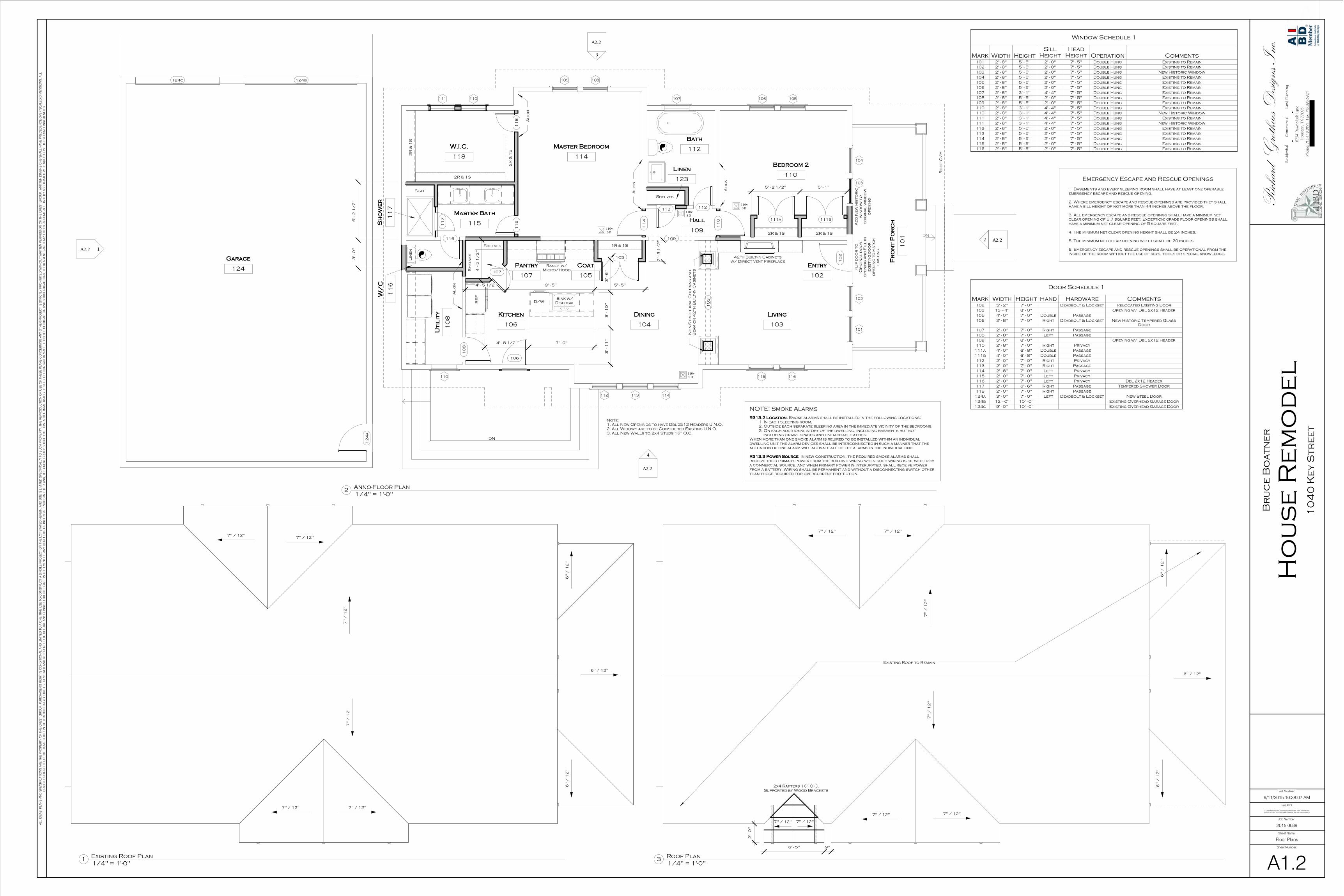
1. Basements and every sleeping room shall have at least one operable
emergency escape and rescue opening.
2. Where emergency escape and rescue openings are provided they shall
have a sill height of not more than 44 inches above the floor.
3. All emergency escape and rescue openings shall have a minimum net
clear opening of 5.7 square feet. Exception: grade floor openings shall
have a minimum net clear opening of 5 square feet.
4. The minimum net clear opening height shall be 24 inches.
5. The minimum net clear opening width shall be 20 inches.
6. Emergency escape and rescue openings shall be operational from the
inside of the room without the use of keys, tools or special knowledge.
Emergency Escape and Rescue Openings
Door Schedule 1
Mark Width Height Hand Hardware Comments102 5' - 2" 7' - 0" Deadbolt & Lockset Relocated Existing Door
103 13' - 4" 8' - 0" Opening w/ Dbl 2x12 Header
105 4' - 0" 7' - 0" Double Passage
106 2' - 8" 7' - 0" Right Deadbolt & Lockset New Historic Tempered Glass
Door
107 2' - 0" 7' - 0" Right Passage
108 2' - 8" 7' - 0" Left Passage
109 5' - 0" 8' - 0" Opening w/ Dbl 2x12 Header
110 2' - 8" 7' - 0" Right Privacy
111a 4' - 0" 6' - 8" Double Passage
111b 4' - 0" 6' - 8" Double Passage
112 2' - 0" 7' - 0" Right Privacy
113 2' - 0" 7' - 0" Right Passage
114 2' - 8" 7' - 0" Left Privacy
115 2' - 0" 7' - 0" Left Privacy
116 2' - 0" 7' - 0" Left Privacy Dbl 2x12 Header
117 2' - 0" 6' - 6" Right Passage Tempered Shower Door
118 2' - 0" 7' - 0" Right Passage
124a 3' - 0" 7' - 0" Left Deadbolt & Lockset New Steel Door
124b 12' - 0" 10' - 0" Existing Overhead Garage Door
124c 9' - 0" 10' - 0" Existing Overhead Garage Door
Window Schedule 1
Mark Width Height
Sill
Height
Head
Height Operation Comments101 2' - 8" 5' - 5" 2' - 0" 7' - 5" Double Hung Existing to Remain
102 2' - 8" 5' - 5" 2' - 0" 7' - 5" Double Hung Existing to Remain
103 2' - 8" 5' - 5" 2' - 0" 7' - 5" Double Hung New Historic Window
104 2' - 8" 5' - 5" 2' - 0" 7' - 5" Double Hung Existing to Remain
105 2' - 8" 5' - 5" 2' - 0" 7' - 5" Double Hung Existing to Remain
106 2' - 8" 5' - 5" 2' - 0" 7' - 5" Double Hung Existing to Remain
107 2' - 8" 3' - 1" 4' - 4" 7' - 5" Double Hung Existing to Remain
108 2' - 8" 5' - 5" 2' - 0" 7' - 5" Double Hung Existing to Remain
109 2' - 8" 5' - 5" 2' - 0" 7' - 5" Double Hung Existing to Remain
110 2' - 8" 3' - 1" 4' - 4" 7' - 5" Double Hung Existing to Remain
110 2' - 8" 3' - 1" 4' - 4" 7' - 5" Double Hung New Historic Window
111 2' - 8" 3' - 1" 4' - 4" 7' - 5" Double Hung Existing to Remain
111 2' - 8" 3' - 1" 4' - 4" 7' - 5" Double Hung New Historic Window
112 2' - 8" 5' - 5" 2' - 0" 7' - 5" Double Hung Existing to Remain
113 2' - 8" 5' - 5" 2' - 0" 7' - 5" Double Hung Existing to Remain
114 2' - 8" 5' - 5" 2' - 0" 7' - 5" Double Hung Existing to Remain
115 2' - 8" 5' - 5" 2' - 0" 7' - 5" Double Hung Existing to Remain
116 2' - 8" 5' - 5" 2' - 0" 7' - 5" Double Hung Existing to Remain
1/4" = 1'-0"2Anno-Floor Plan
Note:
1. All New Openings to have Dbl 2x12 Headers U.N.O.
2. All Widows are to be Considered Existing U.N.O.
3. All New Walls to 2x4 Studs 16" O.C.
1/4" = 1'-0"3Roof Plan
NOTE: Smoke Alarms
R313.2 Location.R313.2 Location.R313.2 Location.R313.2 Location. Smoke alarms shall be installed in the following locations:
1. In each sleeping room,
2. Outside each separate sleeping area in the immediate vicinity of the bedrooms.
3. On each additional story of the dwelling, including basments but not
including crawl spaces and unihabitable attics.
When more than one smoke alarm is reuired to be installed within an individual
dwelling unit the alarm devices shall be interconnected in such a manner that the
actuation of one alarm will activate all of the alarms in the individual unit.
R313.3 Power Source.R313.3 Power Source.R313.3 Power Source.R313.3 Power Source. In new construction, the required smoke alarms shall
receive their primary power from the building wiring when such wiring is served from
a commercial source, and when primary power is interuppted, shall receive power
from a battery. Wiring shall be permanent and without a disconnecting switch other
than those required for overcurrent protection.
1/4" = 1'-0"1Existing Roof Plan

Garage6"
Grade0"
Garage Roof13' - 1"
Lower Ridge16' - 1 3/8"
1st Floor2' - 6"
1st Ceiling11' - 7"
Grade0"
Porch2' - 0"
Top Ridge20' - 2 1/8"
Eave10' - 4 7/8"
Lower Ridge16' - 1 3/8"
Porch Beam9' - 0"
8" Wood
Columns (Typ.)
1st Floor2' - 6"
1st Ceiling11' - 7"
Garage6"Grade
0"
Garage Roof13' - 1"
Porch2' - 0"
Top Ridge20' - 2 1/8"
Eave10' - 4 7/8"Porch Beam9' - 0"
1st Floor2' - 6"
1st Ceiling11' - 7"
Garage6" Grade
0"
Garage Roof13' - 1"
Porch2' - 0"
Top Ridge20' - 2 1/8"
Eave10' - 4 7/8"
Lower Ridge16' - 1 3/8"
Porch Beam9' - 0"
ALL IDEAS, PLANS AND SPECIFICATIONS ARE THE PROPERTY OF THE CREST GROUP. PURCHASER'S RIGHT IS CONDITIONAL AND LIMITED TO A ONE-TIME USE TO CONSTRUCT A SINGLE PROJECT ON THE LOT STATED HEREIN, AND USE IS LIMITED SPECIFICALLY TO SUCH PROPERTY. THE REPRODUCTION OR USE OF THESE PLANS CONCERNING ANY OTHER PROJECT IS STRICTLY PROHIBITED WITHOUT WRITTEN PERMISSION OF THE CREST GROUP. WRITTEN DIMENSIONS SHALL HAVE PRECEDENCE OVER SCALED DIMENSIONS. ALL
PLANS DESDIGNED FOR THE CONSTRUCTION OF THIS BUILDING SHOULD BE REVIEWED AND REFERENCED TO BEFORE ANY CONSTRUCTION BEGINS. IN THE EVENT OF ANY CONFLICTS OR INCONSISTENCIES IN THE PLANS, THE CREST GROUP SHOULD BE CONTACTED IMMEDIATELY. IF NO SUCH CONTACT IS MADE, THEN THE CONTRACTOR AND SUBCONTRACTORS, THEIR AGENTS AND EMPLOYEES, ASSUME ALL LIABILITY ASSOCIATED WITH SUCH CONFLICTS OR INCONSISTENCIES.
Richard Grothues Designs, Inc.
Residential Commercial Land Planning
8734 Dawnblush Lane
Houston, TX 77095
Phone: 713.449.9191 Fax: 713.893.6901
Sheet Number:
Sheet Name:
Job Number:
Last Plot:
Last Modified:
C:\Users\Rick\Dropbox (RGDesigns)\RGDesigns Team Folder\RGDI -2015\2015.0039 - 1040 Key Street\Drawings\1040 Key Historic Rev.rvt
9/11/2015 10:38:09 AM
1040 Key Street
2015.0039
Building Elevations
A2.1
House Remodel
Bruce Boatner
1/4" = 1'-0"1Existing-North Elevation
1/4" = 1'-0"2Existing-South Elevation
1/4" = 1'-0"3Existing-East Elevation
1/4" = 1'-0"4Existing-West Elevation

Garage6"
Grade0"
Garage Roof13' - 1"
Top Ridge20' - 2 1/8"
Lower Ridge16' - 1 3/8"
1st Floor2' - 6"
1st Ceiling11' - 7"
Grade0"
Porch2' - 0"
Top Ridge20' - 2 1/8"
Eave10' - 4 7/8"
Lower Ridge16' - 1 3/8"
Porch Ridge15' - 10 1/8"
101 102 103 104
8.5" - 7"
Tapered Wood
Columns (Typ.)
Existing117 Wood
Siding (typ.)
Existing Gable
Brackets (Typ. U.N.O.)
Existing Composition
Shingles
Existing Composition
Shingles
Existing Wood
Trim (Typ.)
Porch Beam9' - 0"
Raise Gable Vent
to Create Sill to
Protect from
Wind Driven Rain
Existing Composition
Shingles
1st Floor2' - 6"
1st Ceiling11' - 7"
Garage6"Grade
0"
Garage Roof13' - 1"
Porch2' - 0"
24" High Guardrail
Top Ridge20' - 2 1/8"
Eave10' - 4 7/8"
105 106
107
108 109
110 111
Wood
Columns
Existing
Composition
Shingles
Existing117 Wood Siding (typ.)
Existing Gable
Brackets (Typ. U.N.O.)
Existing Wood Trim
(Typ. U.N.O.)
Porch Beam9' - 0"
1st Floor2' - 6"
1st Ceiling11' - 7"
Garage6" Grade
0"
Garage Roof13' - 1"
Porch2' - 0"
Top Ridge20' - 2 1/8"
Eave10' - 4 7/8"
Lower Ridge16' - 1 3/8"
110
112 113 114 115 116
24" High Guardrail
Wood
Columns
Existing
Composition
Shingles
Existing117 Wood Siding (typ.)
Existing Gable
Brackets (Typ. U.N.O.)
Existing Wood Trim
(Typ. U.N.O.)
Gable Brackets
Composition
ShinglesWood Trim
Porch Beam9' - 0"
ALL IDEAS, PLANS AND SPECIFICATIONS ARE THE PROPERTY OF THE CREST GROUP. PURCHASER'S RIGHT IS CONDITIONAL AND LIMITED TO A ONE-TIME USE TO CONSTRUCT A SINGLE PROJECT ON THE LOT STATED HEREIN, AND USE IS LIMITED SPECIFICALLY TO SUCH PROPERTY. THE REPRODUCTION OR USE OF THESE PLANS CONCERNING ANY OTHER PROJECT IS STRICTLY PROHIBITED WITHOUT WRITTEN PERMISSION OF THE CREST GROUP. WRITTEN DIMENSIONS SHALL HAVE PRECEDENCE OVER SCALED DIMENSIONS. ALL
PLANS DESDIGNED FOR THE CONSTRUCTION OF THIS BUILDING SHOULD BE REVIEWED AND REFERENCED TO BEFORE ANY CONSTRUCTION BEGINS. IN THE EVENT OF ANY CONFLICTS OR INCONSISTENCIES IN THE PLANS, THE CREST GROUP SHOULD BE CONTACTED IMMEDIATELY. IF NO SUCH CONTACT IS MADE, THEN THE CONTRACTOR AND SUBCONTRACTORS, THEIR AGENTS AND EMPLOYEES, ASSUME ALL LIABILITY ASSOCIATED WITH SUCH CONFLICTS OR INCONSISTENCIES.
Richard Grothues Designs, Inc.
Residential Commercial Land Planning
8734 Dawnblush Lane
Houston, TX 77095
Phone: 713.449.9191 Fax: 713.893.6901
Sheet Number:
Sheet Name:
Job Number:
Last Plot:
Last Modified:
C:\Users\Rick\Dropbox (RGDesigns)\RGDesigns Team Folder\RGDI -2015\2015.0039 - 1040 Key Street\Drawings\1040 Key Historic Rev.rvt
9/11/2015 10:38:10 AM
1040 Key Street
2015.0039
Building Elevations
A2.2
House Remodel
Bruce Boatner
1/4" = 1'-0"1North Elevation
1/4" = 1'-0"2South Elevation
1/4" = 1'-0"3East Elevation
1/4" = 1'-0"4West Elevation

1040 Key Street Remodel
Legal Description:
LT 10 BLK 133 North Norhill
Address:
1040 Key Street, Houston TX 77009
Current Conditions:
The house is in good condition. House has been previously altered, but date of alterations are unknown.
There are noticeable signs that the front door had previously been relocated, as well as, the removal of
a front window. The porch roof appears to have also been altered and houses in the area that are the
same supports this. The porch columns and railing are not original.
Proposed Work:
Relocate Front door to its original location. Replace non-historic window on east elevation with two
historical windows. Add historic window back to the front of the house. Add glass panel door to west
elevation with a small roof and deck. Change hipped porch roof back to a gable roof. Replace the porch
columns and railing.
Current Building Materials:
The house has all the existing Windows with one exception. Doors, Siding, Trim, Gable brackets, and
remaining windows are original to the house.
Proposed New Materials:
• Glass Panel Door
• Treated Lumber for Deck
• Composition Shingles on Porch Gable Roof
• 117 Siding
• 1x4 Trim Boards
• Salvaged Historic Windows

Existing House Pictures
Front
Side 1
Side 2

Garage
Example of a Similar House in the Area of Gable Porch Roof, Columns, and Railing
4001 Pineridge Street

Signs of Front Door Relocation and Window Removal

Non-Historic Window to be Replaced