cerberus: prototype for an agile inspection and … · american institute of aeronautics and...
TRANSCRIPT
American Institute of Aeronautics and Astronautics
1
CERBERUS: Prototype for an Agile Inspection and
Servicing Satellite Using Thrust-Vectoring Cold-Gas
Propulsion
Larissa Balestrero Machado1, Max Skuhersky2, Markus Wilde3
Florida Institute of Technology, Melbourne, FL, 32901
and
Christopher Brett4
Julius-Maximilians-Universität Würzburg, Würzburg, Germany, 97074
This paper presents the current status of project Cerberus: the development and testing of
a prototype for an agile inspection and servicing satellite using thrust-vectoring cold-gas
propulsion. The Cerberus concept uses a set of three cold-gas thrusters controlled on two-
degree-of-freedom (2DOF) mechanisms mounted on three sides of a hexagonal structure, 120°
apart, providing the spacecraft with 6DOF. A set of two modular small robotic manipulators,
each with 5DOF, enables Cerberus to capture and manipulate its targets. The robotic
manipulators are mounted to two surfaces of the hexagon, while the bottom surface is used to
mount the vehicle on a test platform. Cerberus was designed to be tested in the Orbital
Robotics Interaction, On-orbit servicing, and Navigation (ORION) laboratory at Florida
Institute of Technology, where an OptiTrack motion tracking system is used in conjunction
with on-board optical sensors and laser rangefinders for guidance, navigation, and control.
Nomenclature
A* = nozzle throat area
AERCam = Autonomous Extravehicular Activity Robotic Camera
γ = specific heat ratio
L = distance from geometric center to thruster center point
�̇� = mass flow rate through single thruster
ORION = Orbital Robotic Interaction, On-orbit servicing, and Navigation
P0 = stagnation pressure
R = universal gas constant
SPHERES = Synchronized Position Hold, Engage and Reorient Experimental Satellite
T = thrust force
T0 = stagnation temperature
𝑇𝑛 = thruster number
𝑡𝑐𝑝 = thruster center point
Ve = gas exit velocity
1 Graduate Student, Mechanical & Aerospace Engineering, 150 W University Blvd, Melbourne, FL 32901, AIAA
Student Member. 2 Graduate Student, Mechanical & Aerospace Engineering, 150 W University Blvd, Melbourne, FL 32901, AIAA
Student Member. 3 Assistant Professor, Mechanical & Aerospace Engineering, 150 W University Blvd, Melbourne, FL 32901, AIAA
Member. 4 Graduate Student, Institut für Informatik, Am Hubland, Würzburg, Germany, 97074.
Dow
nloa
ded
by 2
4.12
7.10
2.16
3 on
Oct
ober
7, 2
017
| http
://ar
c.ai
aa.o
rg |
DO
I: 1
0.25
14/6
.201
7-51
16
AIAA SPACE and Astronautics Forum and Exposition
12 - 14 Sep 2017, Orlando, FL
AIAA 2017-5116
Copyright © 2017 by the American Institute of Aeronautics and Astronautics, Inc.
All rights reserved.
AIAA SPACE Forum
American Institute of Aeronautics and Astronautics
2
I. Introduction
ERBERUS is designed as a laboratory prototype of an on-orbit utility vehicle capable of in-space inspection of
defective satellites and of repairing some common spacecraft malfunctions. The envisioned repair activities
include, but are not limited to, repairing surface damage due to micro-meteorites or orbital debris, freeing jammed
mechanisms (such as solar arrays and antennas) and cleaning contaminated solar arrays or optical instruments.1 The
primary mission concept of a Cerberus spacecraft is to be launched as piggy-back payload with high-value
communications or Earth-observation spacecraft. If these spacecraft develop malfunctions, Cerberus would detach,
inspect the defective subsystems and effect repairs, if possible. A secondary mission for a Cerberus spacecraft would
be to capture small space debris objects in the vicinity of high-value assets.
Past and present projects similar to Cerberus are NASA’s Autonomous Extravehicular Activity Robotic Camera
Sprint (AERCam Sprint)2, the Astrobee3, and the Synchronized Position Hold, Engage, Reorient, Experimental
Satellites (Spheres)4; and JAXA’s JEM Internal Ball Camera (Int-Ball)5. The AERCam Sprint was a prototype of a
nitrogen propelled, free-flying, remotely controlled, television camera that was planned to be used for ISS exterior
inspection. The prototype was tested during the STS-87 mission. Weighing around 16 kg with a fly time of 30 minutes,
AERCam Sprint resembles Cerberus dimensions closely.2 Similarly to the AERCam Sprint, project Astrobee is also
a free-flying, remotely controlled, monitoring robot. However, Astrobee is to be mainly operated within the interior
of the ISS using micro fans, taking away some of the tedious monitoring tasks from the crew.3 Project SPHERES is
used on the ISS to test autonomous formation flight and docking capabilities of small spacecraft, using cold gas
propulsion systems. The focus of project SPHERES is therefore related to project Cerberus. Similar to the project
Astrobee, Int-Ball is propelled using micro fans within the ISS. Int-Ball’s main purpose is to reduce the amount of
time Astronauts spend preparing recording devices, which can be as high as 10% of their total working time.5 Cerberus
in this sense follows a past and current research focus of developing an on-orbit maintenance/monitoring device, while
not being directly tied only to operations of ISS but rather focusing on usage on commercial, scientific, and national
security spacecraft. The main objectives of project Cerberus are to demonstrate the ability to locate, track, fly in formation with,
approach and capture target objects in a laboratory environment. The compact, hexagonally shaped vehicle has a
maximum mass design requirement of 27 kg (60 lb). Target identification, position, relative velocity, and attitude
estimation are obtained using a combination of lidar, infrared proximity sensors, and a stereoscopic navigation camera.
The propulsion system consists of three vectoring cold-gas thrusters radially distributed 120° from each other starting
from the top side of the hexagon to meet the requirement for full 6DOF control with a minimum number of actuators.
Three modular slots occupying the remaining sides of the vehicle will provide mounting points for 5DOF robotic
mechanisms for capture and manipulation of targets. The manipulators are designed to be able to grapple targets sized
up to a 3U CubeSat (4 kg). With the modular design, other appendages and/or sensors can also be installed depending
on mission requirements.
The paper describes the Cerberus concept of operations in Section II, then proceeds to provide an overview of the
design in Section III. A brief overview of the control system design and architecture is given in Section IV, followed
by experimental characterization of the thruster performance in Section V. Section VI concludes the paper.
II. Concept of Operations
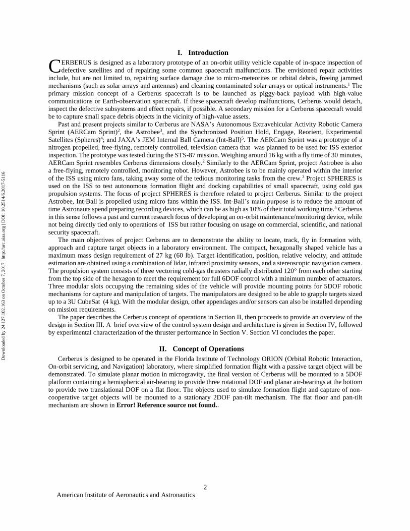
Cerberus is designed to be operated in the Florida Institute of Technology ORION (Orbital Robotic Interaction,
On-orbit servicing, and Navigation) laboratory, where simplified formation flight with a passive target object will be
demonstrated. To simulate planar motion in microgravity, the final version of Cerberus will be mounted to a 5DOF
platform containing a hemispherical air-bearing to provide three rotational DOF and planar air-bearings at the bottom
to provide two translational DOF on a flat floor. The objects used to simulate formation flight and capture of non-
cooperative target objects will be mounted to a stationary 2DOF pan-tilt mechanism. The flat floor and pan-tilt
mechanism are shown in Error! Reference source not found..
C
Dow
nloa
ded
by 2
4.12
7.10
2.16
3 on
Oct
ober
7, 2
017
| http
://ar
c.ai
aa.o
rg |
DO
I: 1
0.25
14/6
.201
7-51
16
American Institute of Aeronautics and Astronautics
3
After Cerberus and the target objects are mounted, the spacecraft will receive the current mission commands,
which will be sent via User Datagram Protocol (UDP) per WiFi to the vehicle from the ground station computer and
then distributed to the appropriate systems aboard the craft. An OptiTrack motion capture system installed in the
ORION lab, combined with the on-board sensors, will be used to accurately track Cerberus’ movements while the
craft performs a search for the target object within the test bed area. Once the target is located, Cerberus will approach
it until the target is within capture range, this phase can be automated or teleoperated.
The next phase is the target capture, which is always performed in teleoperation. Each capturing mechanism has a
camera at its end effector which will display the target object in the user interface so that the operator can maneuver
the capturing mechanisms to reach and capture the target object. Force sensing resistors will also be installed at the
end effector to confirm target capture, and the robotic mechanisms will then hold the target for a predefined amount
of time before releasing the object and relocating to a predefined location, bringing the experiment to an end.
III. Design Overview
A. Structure
The structural frame of the Cerberus spacecraft is a hexagonal box with each side being a 0.2 m by 0.2 m square,
providing three mounting surfaces for the vectoring thrusters and three modular slots for the robotic mechanisms and
other appendages. The structural frame is composed of Aluminum 6061 extrusion beams, making it lightweight and
easily configurable. The front and back panels are made of acrylic sheets and provide mounting interfaces for the laser
range finder, stereoscopic camera and two proximity sensors in the front and two proximity sensors in the back. These
panels are attached to the frame using neodymium magnets for easy access to the internal components.
Internally, the spacecraft contains an acrylic sheet that separates it vertically into two sections and provides more
mounting interfaces for some of the electronic components. The propulsion subsystem internal components such as
the compressed nitrogen tank, manifold, and pressure regulators are located on the back section while the on-board
computer and batteries are located on the front section, attached to the middle plate. The modular slots, base structure
for the thrusters and other supporting structures for some of the internal components are composed of 3D printed
Acrylonitrile Butadiene Styrene (ABS) plastic.
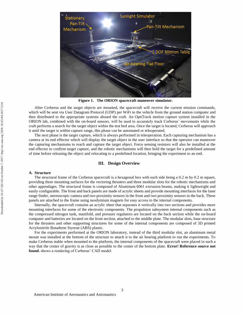
For the experiments performed at the ORION laboratory, instead of the third modular slot, an aluminum metal
mount was installed at the bottom of the structure to attach it to the air bearing platform to run the experiments. To
make Cerberus stable when mounted to the platform, the internal components of the spacecraft were placed in such a
way that the center of gravity is as close as possible to the center of the bottom plate. Error! Reference source not
found. shows a rendering of Cerberus’ CAD model.
Figure 1. The ORION spacecraft maneuver simulator.
Dow
nloa
ded
by 2
4.12
7.10
2.16
3 on
Oct
ober
7, 2
017
| http
://ar
c.ai
aa.o
rg |
DO
I: 1
0.25
14/6
.201
7-51
16
American Institute of Aeronautics and Astronautics
4
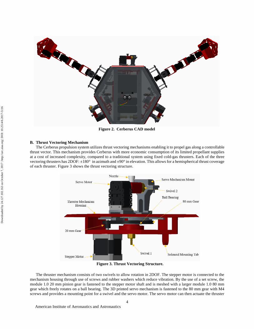
B. Thrust Vectoring Mechanism
The Cerberus propulsion system utilizes thrust vectoring mechanisms enabling it to propel gas along a controllable
thrust vector. This mechanism provides Cerberus with more economic consumption of its limited propellant supplies
at a cost of increased complexity, compared to a traditional system using fixed cold-gas thrusters. Each of the three
vectoring thrusters has 2DOF: ±180° in azimuth and ±90° in elevation. This allows for a hemispherical thrust coverage
of each thruster. Figure 3 shows the thrust vectoring structure.
The thruster mechanism consists of two swivels to allow rotation in 2DOF. The stepper motor is connected to the
mechanism housing through use of screws and rubber washers which reduce vibration. By the use of a set screw, the
module 1.0 20 mm pinion gear is fastened to the stepper motor shaft and is meshed with a larger module 1.0 80 mm
gear which freely rotates on a ball bearing. The 3D printed servo mechanism is fastened to the 80 mm gear with M4
screws and provides a mounting point for a swivel and the servo motor. The servo motor can then actuate the thruster
Figure 2. Cerberus CAD model
Figure 3. Thrust Vectoring Structure.
Dow
nloa
ded
by 2
4.12
7.10
2.16
3 on
Oct
ober
7, 2
017
| http
://ar
c.ai
aa.o
rg |
DO
I: 1
0.25
14/6
.201
7-51
16
American Institute of Aeronautics and Astronautics
5
elevation angle. The stepper and servo motor motions can be controlled to determine the desired thrust vector. The
updated design allows a slip ring to be included, which will prevent the servo wires from being tangled.
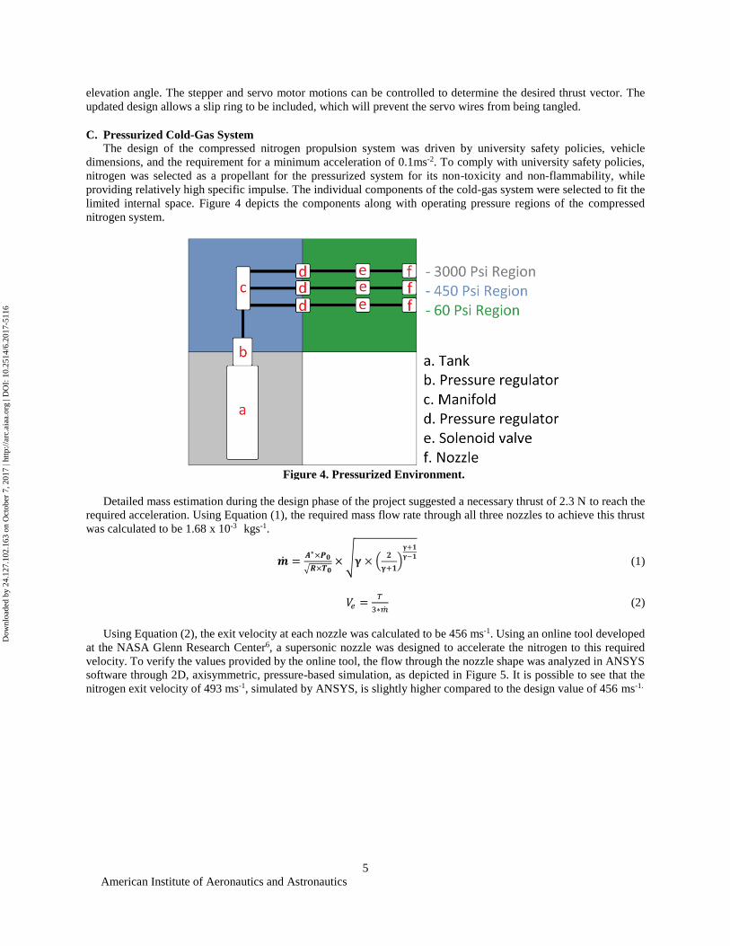
C. Pressurized Cold-Gas System
The design of the compressed nitrogen propulsion system was driven by university safety policies, vehicle
dimensions, and the requirement for a minimum acceleration of 0.1ms-2. To comply with university safety policies,
nitrogen was selected as a propellant for the pressurized system for its non-toxicity and non-flammability, while
providing relatively high specific impulse. The individual components of the cold-gas system were selected to fit the
limited internal space. Figure 4 depicts the components along with operating pressure regions of the compressed
nitrogen system.
Detailed mass estimation during the design phase of the project suggested a necessary thrust of 2.3 N to reach the
required acceleration. Using Equation (1), the required mass flow rate through all three nozzles to achieve this thrust
was calculated to be 1.68 x 10⁻³ kgs-1.
�̇� =𝑨∗×𝑷𝟎
√𝑹×𝑻𝟎× √𝛄 × (
𝟐
𝛄+𝟏)
𝛄+𝟏
𝛄−𝟏 (1)
𝑉𝑒 =𝑇
3∗�̇� (2)
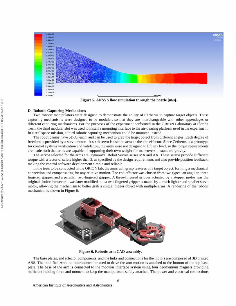
Using Equation (2), the exit velocity at each nozzle was calculated to be 456 ms-1. Using an online tool developed
at the NASA Glenn Research Center6, a supersonic nozzle was designed to accelerate the nitrogen to this required
velocity. To verify the values provided by the online tool, the flow through the nozzle shape was analyzed in ANSYS
software through 2D, axisymmetric, pressure-based simulation, as depicted in Figure 5. It is possible to see that the
nitrogen exit velocity of 493 ms-1, simulated by ANSYS, is slightly higher compared to the design value of 456 ms-1.
Figure 4. Pressurized Environment.
Dow
nloa
ded
by 2
4.12
7.10
2.16
3 on
Oct
ober
7, 2
017
| http
://ar
c.ai
aa.o
rg |
DO
I: 1
0.25
14/6
.201
7-51
16
American Institute of Aeronautics and Astronautics
6
D. Robotic Capturing Mechanisms
Two robotic manipulators were designed to demonstrate the ability of Cerberus to capture target objects. These
capturing mechanisms were designed to be modular, so that they are interchangeable with other appendages or
different capturing mechanisms. For the purposes of the experiment performed in the ORION Laboratory at Florida
Tech, the third modular slot was used to install a mounting interface to the air-bearing platform used in the experiment.
In a real space mission, a third robotic capturing mechanism could be mounted instead.
The robotic arms have 5DOF each, and can be used to grab the target object from different angles. Each degree of
freedom is provided by a servo motor. A sixth servo is used to actuate the end effector. Since Cerberus is a prototype
for control systems verification and validation, the arms were not designed to lift any load, so the torque requirements
are made such that arms are capable of supporting their own weight for maneuvers in standard gravity.
The servos selected for the arms are Dynamixel Robot Servos series MX and AX. These servos provide sufficient
torque with a factor of safety higher than 3, as specified by the design requirements and also provide position feedback,
making the control software development simple and reliable.
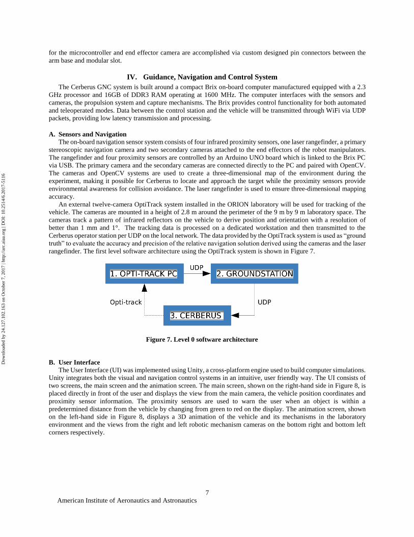
In the tests to be conducted in the ORION lab, the arms will grasp features of a target object, forming a mechanical
connection and compensating for any relative motion. The end effector was chosen from two types: an angular, three
fingered gripper and a parallel, two-fingered gripper. A three-fingered gripper actuated by a stepper motor was the
original choice, however it was later modified into a two-fingered gripper actuated by a much lighter and smaller servo
motor, allowing the mechanism to better grab a single, bigger object with multiple arms. A rendering of the robotic
mechanism is shown in Figure 6.
The base plates, end effector components, and the links and connections for the motors are composed of 3D printed
ABS. The modified Arduino microcontroller used to drive the arm motion is attached to the bottom of the top base
plate. The base of the arm is connected to the modular interface system using four neodymium magnets providing
sufficient holding force and moment to keep the manipulators safely attached. The power and electrical connections
Figure 5. ANSYS flow simulation through the nozzle [m/s].
Figure 6. Robotic arm CAD assembly.
Dow
nloa
ded
by 2
4.12
7.10
2.16
3 on
Oct
ober
7, 2
017
| http
://ar
c.ai
aa.o
rg |
DO
I: 1
0.25
14/6
.201
7-51
16
American Institute of Aeronautics and Astronautics
7
for the microcontroller and end effector camera are accomplished via custom designed pin connectors between the
arm base and modular slot.
IV. Guidance, Navigation and Control System
The Cerberus GNC system is built around a compact Brix on-board computer manufactured equipped with a 2.3
GHz processor and 16GB of DDR3 RAM operating at 1600 MHz. The computer interfaces with the sensors and
cameras, the propulsion system and capture mechanisms. The Brix provides control functionality for both automated
and teleoperated modes. Data between the control station and the vehicle will be transmitted through WiFi via UDP
packets, providing low latency transmission and processing.
A. Sensors and Navigation
The on-board navigation sensor system consists of four infrared proximity sensors, one laser rangefinder, a primary
stereoscopic navigation camera and two secondary cameras attached to the end effectors of the robot manipulators.
The rangefinder and four proximity sensors are controlled by an Arduino UNO board which is linked to the Brix PC
via USB. The primary camera and the secondary cameras are connected directly to the PC and paired with OpenCV.
The cameras and OpenCV systems are used to create a three-dimensional map of the environment during the
experiment, making it possible for Cerberus to locate and approach the target while the proximity sensors provide
environmental awareness for collision avoidance. The laser rangefinder is used to ensure three-dimensional mapping
accuracy.
An external twelve-camera OptiTrack system installed in the ORION laboratory will be used for tracking of the
vehicle. The cameras are mounted in a height of 2.8 m around the perimeter of the 9 m by 9 m laboratory space. The
cameras track a pattern of infrared reflectors on the vehicle to derive position and orientation with a resolution of
better than 1 mm and 1°. The tracking data is processed on a dedicated workstation and then transmitted to the
Cerberus operator station per UDP on the local network. The data provided by the OptiTrack system is used as “ground
truth” to evaluate the accuracy and precision of the relative navigation solution derived using the cameras and the laser
rangefinder. The first level software architecture using the OptiTrack system is shown in Figure 7.
B. User Interface
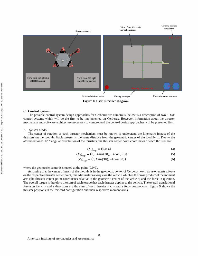
The User Interface (UI) was implemented using Unity, a cross-platform engine used to build computer simulations.
Unity integrates both the visual and navigation control systems in an intuitive, user friendly way. The UI consists of
two screens, the main screen and the animation screen. The main screen, shown on the right-hand side in Figure 8, is
placed directly in front of the user and displays the view from the main camera, the vehicle position coordinates and
proximity sensor information. The proximity sensors are used to warn the user when an object is within a
predetermined distance from the vehicle by changing from green to red on the display. The animation screen, shown
on the left-hand side in Figure 8, displays a 3D animation of the vehicle and its mechanisms in the laboratory
environment and the views from the right and left robotic mechanism cameras on the bottom right and bottom left
corners respectively.
Figure 7. Level 0 software architecture
Dow
nloa
ded
by 2
4.12
7.10
2.16
3 on
Oct
ober
7, 2
017
| http
://ar
c.ai
aa.o
rg |
DO
I: 1
0.25
14/6
.201
7-51
16
American Institute of Aeronautics and Astronautics
8
C. Control System
The possible control system design approaches for Cerberus are numerous, below is a description of two 3DOF
control systems which will be the first to be implemented on Cerberus. However, information about the thruster
mechanism and software architecture necessary to comprehend the control design approaches will be presented first.
1. System Model
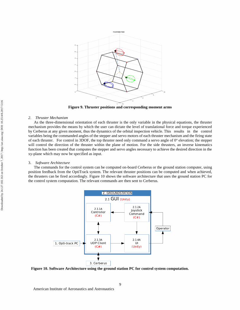
The center of rotation of each thruster mechanism must be known to understand the kinematic impact of the
thrusters on the module. Each thruster is the same distance from the geometric center of the module, L. Due to the
aforementioned 120o angular distribution of the thrusters, the thruster center point coordinates of each thruster are:
(𝑇1)𝑡𝑐𝑝 = (0,0, 𝐿) (4)
(𝑇2)𝑡𝑐𝑝 = (0, −𝐿𝑠𝑖𝑛(30), −𝐿𝑐𝑜𝑠(30)) (5)
(𝑇3)𝑡𝑐𝑝 = (0, 𝐿𝑠𝑖𝑛(30), −𝐿𝑐𝑜𝑠(30)) (6)
where the geometric center is situated at the point (0,0,0).
Assuming that the center of mass of the module is in the geometric center of Cerberus, each thruster exerts a force
on the respective thruster center point, this administers a torque on the vehicle which is the cross product of the moment
arm (the thruster center point coordinates relative to the geometric center of the vehicle) and the force in question.
The overall torque is therefore the sum of each torque that each thruster applies to the vehicle. The overall translational
forces in the x, y and z directions are the sum of each thruster’s x, y and z force components. Figure 9 shows the
thruster positions in the forward configuration and their respective moment arms.
Figure 8. User Interface diagram
Dow
nloa
ded
by 2
4.12
7.10
2.16
3 on
Oct
ober
7, 2
017
| http
://ar
c.ai
aa.o
rg |
DO
I: 1
0.25
14/6
.201
7-51
16
American Institute of Aeronautics and Astronautics
9
2. Thruster Mechanism
As the three-dimensional orientation of each thruster is the only variable in the physical equations, the thruster
mechanism provides the means by which the user can dictate the level of translational force and torque experienced
by Cerberus at any given moment, thus the dynamics of the orbital inspection vehicle. This results in the control
variables being the commanded angles of the stepper and servo motors of each thruster mechanism and the firing state
of each thruster. For control in 3DOF, the top thruster need only command a servo angle of 0o elevation; the stepper
will control the direction of the thruster within the plane of motion. For the side thrusters, an inverse kinematics
function has been created that computes the stepper and servo angles necessary to achieve the desired direction in the
xy-plane which may now be specified as input.
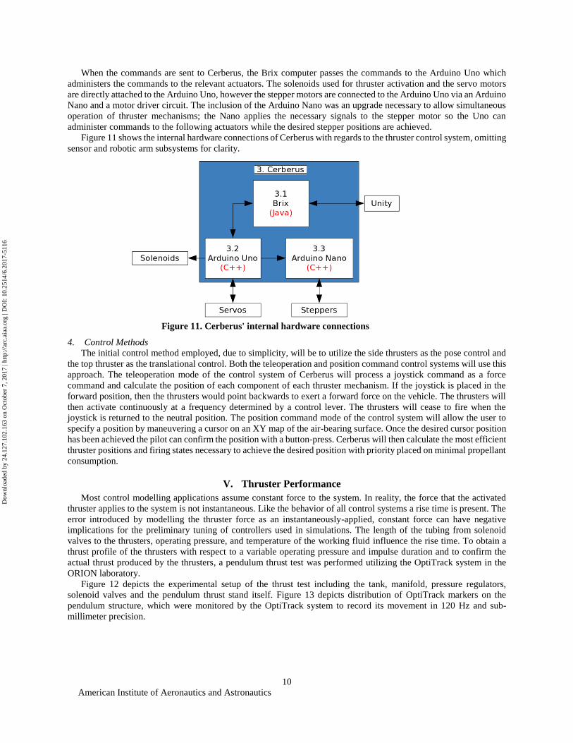
3. Software Architecture
The commands for the control system can be computed on-board Cerberus or the ground station computer, using
position feedback from the OptiTrack system. The relevant thruster positions can be computed and when achieved,
the thrusters can be fired accordingly. Figure 10 shows the software architecture that uses the ground station PC for
the control system computation. The relevant commands are then sent to Cerberus.
Figure 9. Thruster positions and corresponding moment arms
Figure 10. Software Architecture using the ground station PC for control system computation.
Dow
nloa
ded
by 2
4.12
7.10
2.16
3 on
Oct
ober
7, 2
017
| http
://ar
c.ai
aa.o
rg |
DO
I: 1
0.25
14/6
.201
7-51
16
American Institute of Aeronautics and Astronautics
10
When the commands are sent to Cerberus, the Brix computer passes the commands to the Arduino Uno which
administers the commands to the relevant actuators. The solenoids used for thruster activation and the servo motors
are directly attached to the Arduino Uno, however the stepper motors are connected to the Arduino Uno via an Arduino
Nano and a motor driver circuit. The inclusion of the Arduino Nano was an upgrade necessary to allow simultaneous
operation of thruster mechanisms; the Nano applies the necessary signals to the stepper motor so the Uno can
administer commands to the following actuators while the desired stepper positions are achieved.
Figure 11 shows the internal hardware connections of Cerberus with regards to the thruster control system, omitting
sensor and robotic arm subsystems for clarity.
4. Control Methods
The initial control method employed, due to simplicity, will be to utilize the side thrusters as the pose control and
the top thruster as the translational control. Both the teleoperation and position command control systems will use this
approach. The teleoperation mode of the control system of Cerberus will process a joystick command as a force
command and calculate the position of each component of each thruster mechanism. If the joystick is placed in the
forward position, then the thrusters would point backwards to exert a forward force on the vehicle. The thrusters will
then activate continuously at a frequency determined by a control lever. The thrusters will cease to fire when the
joystick is returned to the neutral position. The position command mode of the control system will allow the user to
specify a position by maneuvering a cursor on an XY map of the air-bearing surface. Once the desired cursor position
has been achieved the pilot can confirm the position with a button-press. Cerberus will then calculate the most efficient
thruster positions and firing states necessary to achieve the desired position with priority placed on minimal propellant
consumption.
V. Thruster Performance
Most control modelling applications assume constant force to the system. In reality, the force that the activated
thruster applies to the system is not instantaneous. Like the behavior of all control systems a rise time is present. The
error introduced by modelling the thruster force as an instantaneously-applied, constant force can have negative
implications for the preliminary tuning of controllers used in simulations. The length of the tubing from solenoid
valves to the thrusters, operating pressure, and temperature of the working fluid influence the rise time. To obtain a
thrust profile of the thrusters with respect to a variable operating pressure and impulse duration and to confirm the
actual thrust produced by the thrusters, a pendulum thrust test was performed utilizing the OptiTrack system in the
ORION laboratory.
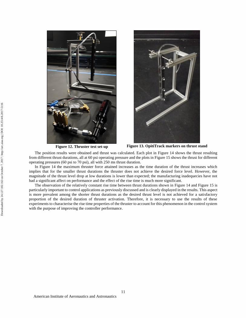
Figure 12 depicts the experimental setup of the thrust test including the tank, manifold, pressure regulators,
solenoid valves and the pendulum thrust stand itself. Figure 13 depicts distribution of OptiTrack markers on the
pendulum structure, which were monitored by the OptiTrack system to record its movement in 120 Hz and sub-
millimeter precision.
Figure 11. Cerberus' internal hardware connections
Dow
nloa
ded
by 2
4.12
7.10
2.16
3 on
Oct
ober
7, 2
017
| http
://ar
c.ai
aa.o
rg |
DO
I: 1
0.25
14/6
.201
7-51
16
American Institute of Aeronautics and Astronautics
11
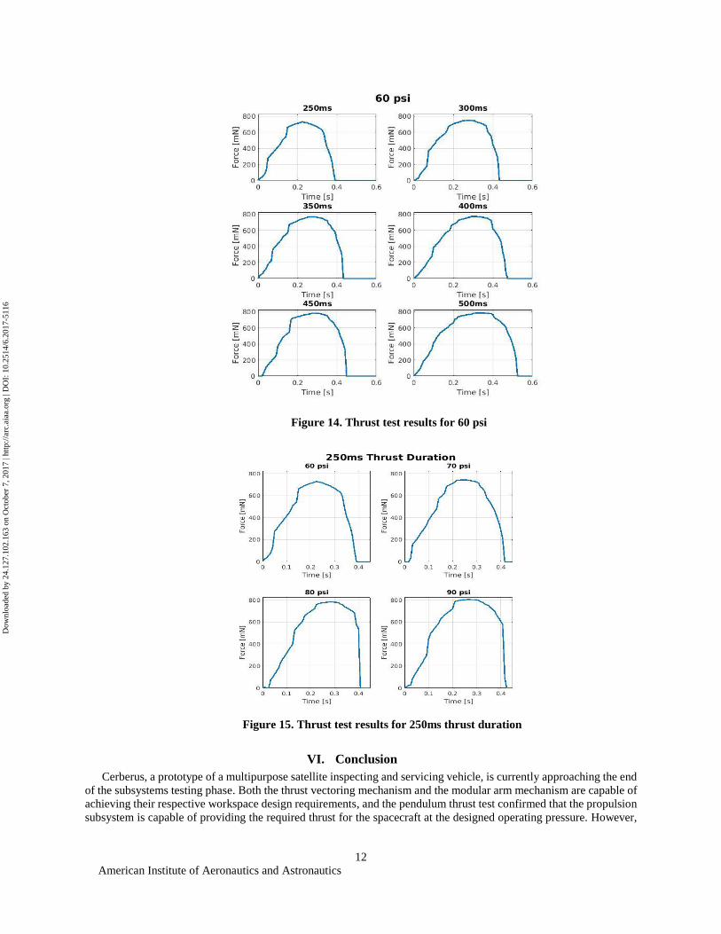
The position results were obtained and thrust was calculated. Each plot in Figure 14 shows the thrust resulting
from different thrust durations, all at 60 psi operating pressure and the plots in Figure 15 shows the thrust for different
operating pressures (60 psi to 70 psi), all with 250 ms thrust duration.
In Figure 14 the maximum thruster force attained increases as the time duration of the thrust increases which
implies that for the smaller thrust durations the thruster does not achieve the desired force level. However, the
magnitude of the thrust level drop at low durations is lower than expected; the manufacturing inadequecies have not
had a significant affect on performance and the effect of the rise time is much more significant.
The observation of the relatively constant rise time between thrust durations shown in Figure 14 and Figure 15 is
particularly important to control applications as previously discussed and is clearly displayed in the results. This aspect
is more prevalent among the shorter thrust durations as the desired thrust level is not achieved for a satisfactory
proportion of the desired duration of thruster activation. Therefore, it is necessary to use the results of these
experiments to characterise the rise time properties of the thruster to account for this phenomenon in the control system
with the purpose of improving the controller performance.
Figure 12. Thruster test set-up
Figure 13. OpitiTrack markers on thrust stand
Dow
nloa
ded
by 2
4.12
7.10
2.16
3 on
Oct
ober
7, 2
017
| http
://ar
c.ai
aa.o
rg |
DO
I: 1
0.25
14/6
.201
7-51
16
American Institute of Aeronautics and Astronautics
12
VI. Conclusion
Cerberus, a prototype of a multipurpose satellite inspecting and servicing vehicle, is currently approaching the end
of the subsystems testing phase. Both the thrust vectoring mechanism and the modular arm mechanism are capable of
achieving their respective workspace design requirements, and the pendulum thrust test confirmed that the propulsion
subsystem is capable of providing the required thrust for the spacecraft at the designed operating pressure. However,
Figure 14. Thrust test results for 60 psi
Figure 15. Thrust test results for 250ms thrust duration
Dow
nloa
ded
by 2
4.12
7.10
2.16
3 on
Oct
ober
7, 2
017
| http
://ar
c.ai
aa.o
rg |
DO
I: 1
0.25
14/6
.201
7-51
16
American Institute of Aeronautics and Astronautics
13
before progressing to the overall system testing phase, additional work is to be performed with regards to the spacecraft
control system design and the structural integration of all components.
The thrust tests will also provide the data for which the controller may be improved by modelling the thruster force
as a force profile which changes with time as opposed to a constant, instantaneously-applied force.
The thruster mechanism for Cerberus has been redesigned and is currently being manufactured while control
system design activities are progressing at the simulation level. Therefore, a full system test is not possible at present
although this will become reality in the near future. The overall system performance testing phase will begin once the
preliminary control system design for the vehicle has been performed and the structural integration is complete.
In order to upgrade Cerberus’ capability to 6DOF, the design of a dynamic mass balancing system and thruster
mechanism housing sockets need to be performed. The two side thruster mechanisms need to be placed below the
spherical air-bearing and in such a way that replicates the same configuration as the current design in order to
successfully simulate and evaluate possible control solutions for a thrust-vectored orbital inspection vehicle such as
Cerberus.
References 1 Tafazoli, M., “A study of on-orbit spacecraft failures,” Acta Astronautica, Vol. 64, Iss. 2-3, 2009, pp. 195 – 205, doi:
10.1016/j.actaastro.2008.07.019. 2 Pedersen, L., Kortenkamp, D., Wettergreen, D., and Nourbakhsh, I., “A Survey of Space Robotics,” Proceedings of the 7th
International Symposium of Artificial Intelligence, Robotics and Automation in Space (i-SAIRAS-03), 2003, pp. 1 – 8. 3 Bualat, M., Barlow, J., Fong, T., Provencher, C., Smith, T., and Zuniga, A., “Astrobee: Developing a Free-flying Robot for the
International Space Station,” AIAA SPACE 2015 Conference and Exposition, Pasadena, CA, 2015, AIAA paper 2015-4643, doi:
10.2514/6.2015-4643. 4 Mohan, S., Saenz-Otero, A., Nolet, S., Miller, D. W., and Sell, S., “SPHERES flight operations testing and execution,” Acta
Astronautica, Vol. 65, Iss. 7-8, 2009, pp. 1121 – 1132, doi: 10.1016/j.actaastro.2009.03.039. 5 John, T., “An Adorable Floating Robot is Helping Astronauts on the ISS,” Times, July 17, 2017. 6 Benson, T., “MOC Nozzle,” NASA Glenn Research Center, August 19th, 2014, Web, url: https://www.grc.nasa.gov/www/k-
12/UndergradProgs/index.htm, accessed: August 11, 2017.
Dow
nloa
ded
by 2
4.12
7.10
2.16
3 on
Oct
ober
7, 2
017
| http
://ar
c.ai
aa.o
rg |
DO
I: 1
0.25
14/6
.201
7-51
16