cerabar m pmc51, pmp51, pmp55 (ba) -...
TRANSCRIPT

BA00385P/00/EN/19.14
71269382
Valid from software version:
01.00.zz
Operating Instructions
Cerabar M PMC51, PMP51, PMP55
Process pressure measurement
Cerabar M Analog
2 Endress+Hauser
A0023555
TAG No.: XXX000
Ser. No.: X000X000000
Order code 00X00-XXXX0XX0XXX
www.endress.com/deviceviewer Endress+Hauser Operations App
Serial number

Cerabar M Analog Table of contents
Endress+Hauser 3
Table of contents
1 Safety instructions . . . . . . . . . . . . . . . . 4
1.1 Designated use . . . . . . . . . . . . . . . . . . . . . . . . . . . . 4
1.2 Installation, commissioning and operation . . . . . . . . 4
1.3 Operational and process safety . . . . . . . . . . . . . . . . . 4
1.4 Notes on safety conventions and icons . . . . . . . . . . . 5
2 Identification . . . . . . . . . . . . . . . . . . . . 6
2.1 Product identification . . . . . . . . . . . . . . . . . . . . . . . 6
2.2 Device designation . . . . . . . . . . . . . . . . . . . . . . . . . 6
2.3 Scope of delivery . . . . . . . . . . . . . . . . . . . . . . . . . . . 8
2.4 CE mark, Declaration of Conformity . . . . . . . . . . . . 9
2.5 Registered trademarks . . . . . . . . . . . . . . . . . . . . . . . 9
3 Installation . . . . . . . . . . . . . . . . . . . . . 10
3.1 Incoming acceptance, transport, storage . . . . . . . . . 10
3.2 Installation conditions . . . . . . . . . . . . . . . . . . . . . . 10
3.3 Installation instructions . . . . . . . . . . . . . . . . . . . . . 11
3.4 Closing the housing cover . . . . . . . . . . . . . . . . . . . 20
3.5 Mounting of the profile seal for universal process
mounting adapter . . . . . . . . . . . . . . . . . . . . . . . . . 20
3.6 Post-installation check . . . . . . . . . . . . . . . . . . . . . . 20
4 Wiring . . . . . . . . . . . . . . . . . . . . . . . . 21
4.1 Connecting the device . . . . . . . . . . . . . . . . . . . . . . 21
4.2 Connecting the measuring unit . . . . . . . . . . . . . . . 23
4.3 Potential equalization . . . . . . . . . . . . . . . . . . . . . . 23
4.4 Overvoltage protection (optional) . . . . . . . . . . . . . . 24
4.5 Post-connection check . . . . . . . . . . . . . . . . . . . . . . 25
5 Operation . . . . . . . . . . . . . . . . . . . . . . 26
5.1 Position of operating elements . . . . . . . . . . . . . . . . 26
5.2 Using the device display (optional) . . . . . . . . . . . . . 27
6 Commissioning. . . . . . . . . . . . . . . . . . 29
6.1 Function check . . . . . . . . . . . . . . . . . . . . . . . . . . . 29
6.2 Commissioning . . . . . . . . . . . . . . . . . . . . . . . . . . . 29
7 Maintenance. . . . . . . . . . . . . . . . . . . . 30
7.1 Cleaning instructions . . . . . . . . . . . . . . . . . . . . . . . 30
7.2 Exterior cleaning . . . . . . . . . . . . . . . . . . . . . . . . . . 30
8 Troubleshooting . . . . . . . . . . . . . . . . . 31
8.1 Messages . . . . . . . . . . . . . . . . . . . . . . . . . . . . . . . . 31
8.2 Measures . . . . . . . . . . . . . . . . . . . . . . . . . . . . . . . 31
8.3 Response of output to errors . . . . . . . . . . . . . . . . . 31
8.4 Repair . . . . . . . . . . . . . . . . . . . . . . . . . . . . . . . . . . 31
8.5 Spare Parts . . . . . . . . . . . . . . . . . . . . . . . . . . . . . . 31
8.6 Return . . . . . . . . . . . . . . . . . . . . . . . . . . . . . . . . . 32
8.7 Disposal . . . . . . . . . . . . . . . . . . . . . . . . . . . . . . . . 32
8.8 Software history . . . . . . . . . . . . . . . . . . . . . . . . . . 32
9 Technical data . . . . . . . . . . . . . . . . . . . 33
Index . . . . . . . . . . . . . . . . . . . . . . . . . . . . . . 34

Safety instructions Cerabar M Analog
4 Endress+Hauser
1 Safety instructions
1.1 Designated use
The Cerabar M is a pressure transmitter for measuring pressure and level.
The manufacturer accepts no liability for damages resulting from incorrect use or use other than that
designated.
1.2 Installation, commissioning and operation
The device is designed to meet state-of-the-art safety requirements and complies with applicable
standards and EU regulations. If used incorrectly or for applications for which it is not intended,
however, it can be a source of application-related danger, e.g. product overflow due to incorrect
installation or configuration. For this reason, installation, connection to the electricity supply,
commissioning, operation and maintenance of the measuring system must only be carried out by
trained, qualified specialists authorized to perform such work by the facility's owner-operator. The
specialist staff must have read and understood these Operating Instructions and must follow the
instructions they contain. Modifications and repairs to the devices are permissible only if they are
expressly approved in the Operating Instructions. Pay particular attention to the technical data and
information on the nameplate.
1.3 Operational and process safety
Alternative monitoring measures have to be taken while configuring, testing or servicing the device
to ensure the operational and process safety.
# Warning!
Dismantle device only when depressurized!

Cerabar M Analog Safety instructions
Endress+Hauser 5
1.4 Notes on safety conventions and icons
In order to highlight safety-relevant or alternative operating procedures in the manual, the following
conventions have been used, each indicated by a corresponding icon in the margin.
Symbol Meaning
#Warning!
A warning highlights actions or procedures which, if not performed correctly, will lead to serious
personal injury, a safety hazard or the destruction of the device.
"Caution!
Caution highlights actions or procedures which, if not performed correctly, can lead to personal
injury or the incorrect operation of the device.
!Note!
A note highlights actions or procedures which, if not performed correctly, can have an indirect
effect on operation or trigger an unexpected response on the part of the device.
% Direct current
A terminal to which DC voltage is applied or through which direct current flows.
&Alternating current
A terminal to which alternating voltage (sine-wave) is applied or through which alternating current
flows.
)Ground connection
A grounded terminal, which as far as the operator is concerned, is already grounded by means of a
grounding system.
* Protective ground connection
A terminal which must be connected to ground prior to establishing any other connections.
+Equipotential connection
A connection that has to be connected to the plant grounding system: This may be a potential
equalization line or a star grounding system depending on national or company codes of practice.
Connecting cable immunity to temperature change
Indicates that the connecting cables have to withstand a temperature of 85°C at least.
Safety instructions
Observe the safety instructions in the associated Operating Instructions.
>=t 85°C

Identification Cerabar M Analog
6 Endress+Hauser
2 Identification
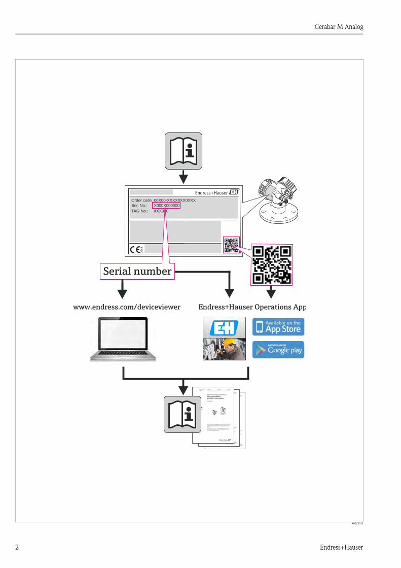
2.1 Product identification
The following options are available for identification of the measuring device:
• Nameplate specifications
• Order code with breakdown of the device features on the delivery note
• Enter serial numbers from nameplates in W@M Device Viewer
(www.endress.com/deviceviewer): All information about the measuring device is displayed.
For an overview of the technical documentation provided, enter the serial number from the
nameplates in the W@M Device Viewer (www.endress.com/deviceviewer).
2.2 Device designation
2.2.1 Nameplate
! Note!
• The MWP (maximum working pressure) is specified on the nameplate. This value refers to a
reference temperature of 20°C (68°F) or 100°F (38 °C) for ANSI flanges.
• The pressure values permitted at higher temperatures can be found in the following standards:
– EN 1092-1: 2001 Tab. 18 1)
– ASME B 16.5a – 1998 Tab. 2-2.2 F316
– ASME B 16.5a – 1998 Tab. 2.3.8 N10276
– JIS B 2220
• The test pressure corresponds to the over pressure limit (OPL) of the device = MWP x 1.5 2).
• The Pressure Equipment Directive (EC Directive 97/23/EC) uses the abbreviation "PS". The
abbreviation "PS" corresponds to the MWP (maximum working pressure) of the measuring
device.
1) With regard to their stability-temperature property, the materials 1.4435 and 1.4404 are grouped together under 13EO
in EN 1092-1 Tab. 18. The chemical composition of the two materials can be identical.
2) The equation does not apply for PMP51 and PMP55 with a 40 bar (600 psi) or a 100 bar (1500 psi) measuring cell.

Cerabar M Analog Identification
Endress+Hauser 7
Aluminum housing
P01-xMx5xxxx-18-xx-xx-xx-000
Fig. 1: Nameplate
1 Device name
2 Order code (for re-orders)
3 Serial number (for identification)
4 Extended order code (complete)
5 MWP (maximum working pressure)
6 Electronic version (output signal)
7 Min./max. span
8 Nominal measuring range
9 Supply voltage
10 Unit of length
11 No entry
12 ID number of notified body with regard to Pressure Equipment Directive (optional)
13 Approvals
14 Device version
15 Software version
16 Degree of protection
17 Wetted materials
18 Approval-specific information
Devices suitable for oxygen applications are fitted with an additional nameplate.
P01-xxxxxxxx-18-xx-xx-xx-000
Fig. 2: Additional nameplate for devices suitable for oxygen applications
1 Maximum pressure for oxygen applications
2 Maximum temperature for oxygen applications
3 Layout identification of the nameplate
ex works FW:
Dev.Rev.:
25
00
02
75
5-C
Ext. order code:Ser. no.:
U=Span
P
MWP
Order code:
Made in Germany, D-79689 Maulburg Mat.:
25
00
02
75
6-EL=
15
12 3
46 7
8 9 10
1112
1314
5
16
17
18
18
PmaxTmax
for oxygen serviceBei Sauerstoffeinsatz/
312

Identification Cerabar M Analog
8 Endress+Hauser
Stainless steel housing, hygienic
P01-xMx5xxxx-18-xx-xx-xx-001
Fig. 3: Nameplate
1 Device name
2 Order code (for re-orders)
3 Serial number (for identification)
4 Extended order code (complete)
5 Nominal measuring range
6 MWP (maximum working pressure)
7 Length data
8 Electronic version (output signal)
9 Supply voltage
10 Min./max. span
11 Wetted materials
12 Approval-specific information
13 No entry
14 ID number of notified body with regard to Pressure Equipment Directive (optional)
15 No entry
16 Software version
17 Device version
18 Degree of protection
Devices with certificates are fitted with an additional plate.
P01-xMx5xxxx-18-xx-xx-xx-002
Fig. 4: Additional nameplate for devices with certificates
1 Approval-specific information
2.3 Scope of delivery
The scope of delivery comprises:
• Device
• Optional accessories
Documentation supplied:
• The Operating Instructions BA00385P is available on the Internet.
See: www.endress.com Download
• Brief Operating Instructions: KA01036P
• Final inspection report
• Optional: factory calibration form, test certificates
00
27
57
-A
p
Order code:
Ext. order code:
Ser. no.:
MWP
D-79689 MaulburgMade in Germany,
ex works FW
U= Dev.Rev.:
L=
Span
Mat.:
00
27
58
-C
16
17
15
1
23
44
4
6
78
910
11
12
12
13
145
18
00
27
59
-B
1
1

Cerabar M Analog Identification
Endress+Hauser 9
2.4 CE mark, Declaration of Conformity
The devices are designed to meet state-of-the-art safety requirements, have been tested and left the
factory in a condition in which they are safe to operate. The devices comply with the applicable
standards and regulations as listed in the EC Declaration of Conformity and thus comply with the
statutory requirements of the EC Directives. Endress+Hauser confirms the conformity of the device
by affixing to it the CE mark.
2.5 Registered trademarks
KALREZ, VITON, TEFLON
Registered trademark of E.I. Du Pont de Nemours & Co., Wilmington, USA
TRI-CLAMP
Registered trademark of Ladish & Co., Inc., Kenosha, USA
GORE-TEX®
Registered trademark of W.L. Gore & Associates, Inc., USA
Installation Cerabar M Analog
10 Endress+Hauser
3 Installation
3.1 Incoming acceptance, transport, storage
3.1.1 Incoming acceptance
• Check the packaging and the contents for damage.
• Check the shipment, make sure nothing is missing and that the scope of supply matches your
order.
3.1.2 Transport
" Caution!
Follow the safety instructions and transport conditions for devices of more than 18 kg (39.69 lbs).
Transport the measuring device to the measuring point in its original packaging or at the process
connection.
3.1.3 Storage
The device must be stored in a dry, clean area and protected against damage from impact
(EN 837-2).
Storage temperature range:
See Technical Information for Cerabar M TI00436P.
3.2 Installation conditions
3.2.1 Dimensions
For dimensions, please refer to the Technical Information for Cerabar M TI00436P, "Mechanical
construction" section.

Cerabar M Analog Installation
Endress+Hauser 11
3.3 Installation instructions
! Note!
• Due to the orientation of the Cerabar M, there may be a shift in the zero point, i.e. when the
container is empty or partially full, the measured value does not display zero. You can correct this
zero point shift ä 27, Section 5.1.2 "Function of the operating elements".
• For PMP55, please refer to Section 3.3.2 "Installation instructions for devices with diaphragm
seals – PMP55", ä 14.
• Endress+Hauser offers a mounting bracket for installing on pipes or walls.
ä 17, Section 3.3.5 "Wall and pipe mounting (optional)".
3.3.1 Installation instructions for devices without diaphragm seals –
PMP51, PMC51
! Note!
• If a heated Cerabar M is cooled during the cleaning process (e.g. by cold water), a vacuum
develops for a short time, whereby moisture can penetrate the sensor through the pressure
compensation (1). If this is the case, mount the Cerabar M with the pressure compensation (1)
pointing downwards.
• Keep the pressure compensation and GORE-TEX® filter (1) free from contamination.
• Cerabar M transmitters without diaphragm seals are mounted as per the norms for a manometer
(DIN EN 837-2). We recommend the use of shutoff devices and siphons. The orientation depends
on the measuring application.
• Do not clean or touch process isolating diaphragms with hard or pointed objects.
• The device must be installed as follows in order to comply with the cleanability requirements of
the ASME-BPE (Part SD Cleanibility).:
1
1
1

Installation Cerabar M Analog
12 Endress+Hauser
Pressure measurement in gases
P01-PMx5xxxx-11-xx-xx-xx-003
Fig. 5: Measuring arrangement for pressure measurement in gases
1 Cerabar M
2 Shutoff device
• Mount the Cerabar M with the shutoff device above the tapping point so that any condensate can
flow into the process.
Pressure measurement in steams
P01-PMx5xxxx-11-xx-xx-xx-004
Fig. 6: Measuring arrangement for pressure measurement in steams
1 Cerabar M
2 Shutoff device
3 U-shaped siphon
4 Circular siphon
• Mount Cerabar M with siphon above the tapping point.
• Fill the siphon with liquid before commissioning.
The siphon reduces the temperature to almost the ambient temperature.
➁
➀
➂
➀
➁
➃
➀
➁

Cerabar M Analog Installation
Endress+Hauser 13
Pressure measurement in liquids
P01-PMx5xxxx-11-xx-xx-xx-005
Fig. 7: Measuring arrangement for pressure measurement in liquids
1 Cerabar M
2 Shutoff device
• Mount Cerabar M with shutoff device below or at the same level as the tapping point.
Level measurement
P01-xMx5xxxx-11-xx-xx-xx-000
Fig. 8: Measuring arrangement for level
• Always install the Cerabar M below the lowest measuring point.
• Do not mount the device in the filling curtain or at a point in the tank which could be affected by
pressure pulses from an agitator.
• Do not mount the device in the suction area of a pump.
• The calibration and functional test can be carried out more easily if you mount the device
downstream of a shutoff device.
PVDF interchangeable threaded boss
! Note!
A maximum torque of 7 Nm (5.16 lbs ft) is permitted for devices with a PVDF interchangeable
threaded boss. The thread connection may become loose at high temperatures and pressures. This
means that the integrity of the thread must be checked regularly and may need to be tightened using
the torque given above. Teflon tape is recommended for sealing the 1/2 NPT thread.
➁
➀

Installation Cerabar M Analog
14 Endress+Hauser
3.3.2 Installation instructions for devices with diaphragm seals –
PMP55
! Note!
• Cerabar M devices with diaphragm seals are screwed in, flanged or clamped, depending on the
type of diaphragm seal.
• A diaphragm seal and the pressure transmitter together form a closed, oil-filled calibrated system.
The fill fluid hole is sealed and may not be opened.
• Do not clean or touch the process isolating diaphragm of the diaphragm seal with hard or pointed
objects.
• Do not remove process isolating diaphragm protection until shortly before installation.
• When using a mounting bracket, sufficient strain relief must be ensured for the capillaries in order
to prevent the capillary bending down (bending radius 100 mm (3.94 in)).
• Please note that the hydrostatic pressure of the liquid columns in the capillaries can cause zero
point shift. The zero point shift can be corrected.
• Please observe the application limits of the diaphragm seal filling oil as detailed in the Technical
Information for Cerabar M TI00436P, "Planning instructions for diaphragm seal systems" section.
In order to obtain more precise measurement results and to avoid a defect in the device, mount the
capillaries as follows:
• Vibration-free (in order to avoid additional pressure fluctuations)
• Not in the vicinity of heating or cooling lines
• Insulate if the ambient temperature is below or above the reference temperature
• With a bending radius of 100 mm (3.94 in).

Cerabar M Analog Installation
Endress+Hauser 15
Vacuum application
For applications under vacuum, Endress+Hauser recommends mounting the pressure transmitter
below the diaphragm seal. This prevents vacuum loading of the diaphragm seal caused by the
presence of filling oil in the capillaries.
When the pressure transmitter is mounted above the diaphragm seal, the maximum height
difference H1 in accordance with the illustration below left must not be exceeded. The maximum
height difference depends on the density of the filling oil and the smallest ever pressure that is
permitted to occur at the diaphragm seal (empty container), see illustration below right.
Mounting with temperature isolator
P01-PMx5xxxx-11-xx-xx-xx-008
Endress+Hauser recommends the use of temperature isolators in the event of constant extreme
medium temperatures which lead to the maximum permissible electronics temperature of +85°C
(+185°F) being exceeded. To minimize the influence of rising heat, Endress+Hauser recommends
the device be mounted horizontally or with the housing pointing downwards.
The additional installation height also brings about a zero point shift of approx. 21 mbar (0.315 psi)
due to the hydrostatic column in the temperature isolator. You can correct this zero point shift.
ä 27 "Function of the operating elements".
P01-PMx5xxxx-11-xx-xx-xx-006
Fig. 9: Installation above the diaphragm
seal
P01-PMP75xxx-05-xx-xx-en-011
Fig. 10: Diagram of maximum installation height above the
diaphragm seal for vacuum applications, depending on
the pressure at the diaphragm seal
H1
0.0
2.0
4.0
6.0
8.0
10.0
12.0
50 100 300 400 500 600 700 800 900 1000200
Inert oil
High temperatureoil
Vegetable oil
Silicone oil
Pressure at diaphragm seal [mbarabs]H
eig
ht
diffe
ren
ce
H1
[m]
Low temperature oil
max. 115

Installation Cerabar M Analog
16 Endress+Hauser
3.3.3 Seal for flange mounting
P01-FMD7xxxx-11-xx-xx-xx-002
Fig. 11: Mounting the versions with a flange
1 Process isolating diaphragm
2 Seal
# Warning!
The seal is not allowed to press against the process isolating diaphragm as this could affect the
measurement result.
3.3.4 Thermal insulation – PMP55
The PMP55 may only be insulated up to a certain height. The maximum permitted insulation height
is indicated on the devices and applies to an insulation material with a heat conductivity
0.04 W/(m x K) and to the maximum permitted ambient and process temperature ( see table
below). The data were determined under the most critical application "quiescent air".
P01-PMx5xxxx-11-xx-xx-xx-010
Fig. 12: Maximum permitted insulation height, here indicated on a PMP55 with a flange
➁➀
� 0.04�W
m K•
TP
TA
PMP55
Ambient temperature (TA) 70°C (158°F)
Process temperature (TP) Max. 400°C (752°F), depending on the diaphragm seal filling oil used (see
TI00436PEN)

Cerabar M Analog Installation
Endress+Hauser 17
3.3.5 Wall and pipe mounting (optional)
Endress+Hauser offers a mounting bracket for installing on pipes or walls (for pipes from 1 1/4" up
to 2" diameter).
P01-xMx5xxxx-06-xx-xx-xx-001
Please note the following when mounting:
• Devices with capillary tubes: mount capillaries with a bending radius 100 mm (3.94 in).
• When mounting on a pipe, tighten the nuts on the bracket uniformly with a torque of
at least 5 Nm (3.69 lbs ft).
52 (
2.05
)
140 (
5.5
1)
122 (
4.8
)
70 (2.76)
6 (0.24)
mm (in)

Installation Cerabar M Analog
18 Endress+Hauser
3.3.6 Assembling and mounting the "separate housing" version
P01-XMx5xxxx-11-xx-xx-xx-009
Fig. 13: "Separate housing" version
1 In the case of the "separate housing" version, the sensor is delivered with the process connection and cable ready
mounted.
2 Cable with connection jack
3 Pressure compensation
4 Connector
5 Locking screw
6 Housing mounted with housing adapter, included
7 Mounting bracket provided, suitable for pipe and wall mounting (for pipes from 1 1/4" up to 2" diameter)
Assembly and mounting
1. Insert the connector (item 4) into the corresponding connection jack of the cable (item 2).
2. Plug the cable into the housing adapter (item 6).
3. Tighten the locking screw (item 5).
4. Mount the housing on a wall or pipe using the mounting bracket (item 7).
When mounting on a pipe, tighten the nuts on the bracket uniformly with a torque of at least
5 Nm (3.69 lbs ft).
Mount the cable with a bending radius (r) 120 mm (4.72 in).
r � 120 mm1
2
34
5
6
7
7
Cerabar M Analog Installation
Endress+Hauser 19
3.3.7 PMP51, version prepared for diaphragm seal mount –
welding recommendation
P01-PMP71xxx-11-xx-xx-xx-000
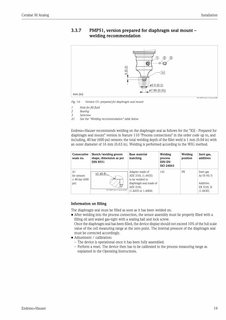
Fig. 14: Version U1: prepared for diaphragm seal mount
1 Hole for fill fluid
2 Bearing
3 Setscrew
A1 See the "Welding recommendation" table below
Endress+Hauser recommends welding on the diaphragm seal as follows for the "XSJ - Prepared for
diaphragm seal mount" version in feature 110 "Process connections" in the order code up to, and
including, 40 bar (600 psi) sensors: the total welding depth of the fillet weld is 1 mm (0.04 in) with
an outer diameter of 16 mm (0.63 in). Welding is performed according to the WIG method.
Information on filling
The diaphragm seal must be filled as soon as it has been welded on.
• After welding into the process connection, the sensor assembly must be properly filled with a
filling oil and sealed gas-tight with a sealing ball and lock screw.
Once the diaphragm seal has been filled, the device display should not exceed 10% of the full scale
value of the cell measuring range at the zero point. The internal pressure of the diaphragm seal
must be corrected accordingly.
• Adjustment / calibration:
– The device is operational once it has been fully assembled.
– Perform a reset. The device then has to be calibrated to the process measuring range as
explained in the Operating Instructions.
ø2.5 (0.1)
5 (0
.2)
➀ ➂➁
ø7.95 (0.31)
A1
mm (in)
Consecutive
seam no.
Sketch/welding groove
shape, dimension as per
DIN 8551
Base material
matching
Welding
process
DIN EN
ISO 24063
Welding
position
Inert gas,
additives
A1
for sensors
40 bar (600
psi)
P01-PMP71xxx-11-xx-xx-xx-001
Adapter made of
AISI 316L (1.4435)
to be welded to
diaphragm seal made of
AISI 316L
(1.4435 or 1.4404)
141 PB Inert gas
Ar/H 95/5
Additive:
ER 316L Si
(1.4430)
s1 a0.8

Installation Cerabar M Analog
20 Endress+Hauser
3.4 Closing the housing cover
! Note!
When closing the housing cover, please ensure that the thread of the cover and housing are free
from dirt, e.g. sand.If you feel any resistance when closing the cover, check the thread on both again
to ensure that they are free from dirt.
3.4.1 Closing the cover on the stainless steel housing
P01-XMx5xxxx-17-xx-xx-xx-001
Fig. 15: Closing the cover
The cover for the electronics compartment is tightened by hand at the housing until the stop. The
screw serves as DustEx protection (only available for devices with DustEx approval).
3.5 Mounting of the profile seal for universal process
mounting adapter
For details on mounting, see KA00096F/00/A3.
3.6 Post-installation check
After installing the device, carry out the following checks:
• Are all screws firmly tightened?
• Is the housing cover screwed down tight?
Cerabar M Analog Wiring
Endress+Hauser 21
4 Wiring
4.1 Connecting the device
# Warning!
Risk of electric shock and/or explosion in hazardous areas! In a wet environment, do not open the
cover if voltage is present.
! Note!
• A suitable circuit breaker must be provided for the device in accordance with IEC/EN61010.
• Devices with integrated overvoltage protection must be grounded.
• Protective circuits against reverse polarity, HF influences and overvoltage peaks are integrated.
The procedure
1. Check that the supply voltage corresponds to the supply voltage indicated on the nameplate.
2. Switch off the supply voltage before connecting the device.
3. Remove housing cover.
4. Guide the cable through the gland. Preferably use a twisted, shielded two-wire cable.
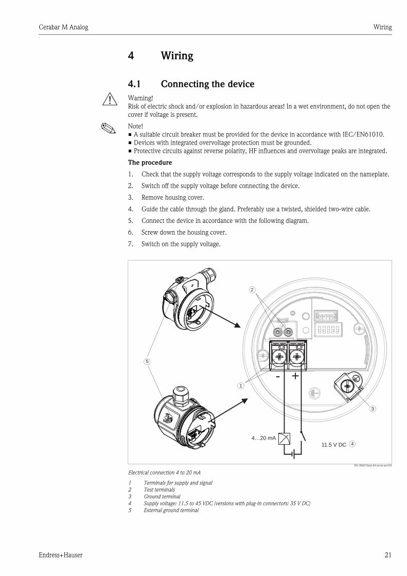
5. Connect the device in accordance with the following diagram.
6. Screw down the housing cover.
7. Switch on the supply voltage.
P01-PMD55xxx-04-xx-xx-xx-010
Electrical connection 4 to 20 mA
1 Terminals for supply and signal
2 Test terminals
3 Ground terminal
4 Supply voltage: 11.5 to 45 VDC (versions with plug-in connectors: 35 V DC)
5 External ground terminal
4…20 mA
11.5 V DC
- +1
2
3
4
5

Wiring Cerabar M Analog
22 Endress+Hauser
4.1.1 Devices with Harting connector Han7D
P01-xMD7xxxx-04-xx-xx-xx-000
Fig. 16: Left: electrical connection for devices with a Harting connector Han7D
Right: view of the connection at the device
4.1.2 Connecting devices with an M12 connector
PIN assignment for M12 connector
4.1.3 Devices with 7/8" plug
PIN assignment for 7/8" connector
4.1.4 Devices with valve connector
P01-xMx5xxxx-04-xx-xx-xx-005
Fig. 17: BN = brown, BU = blue, GNYE = green/yellow; Left: electrical connection for devices with a valve connector
Right: view of the connector at the device
Han7D
–+
+ – –
+
15
4
67
8
23
A0011175
PIN Meaning
1 Signal +
2 Not assigned
3 Signal –
4 Earth
A0011176
PIN Meaning
1 Signal –
2 Signal +
3 Shield
4 Not assigned
21
34
+
–
nc
2
1
4
3
–+
BN BU GNYE 12
3
+–
1 2 3

Cerabar M Analog Wiring
Endress+Hauser 23
4.2 Connecting the measuring unit
4.2.1 Supply voltage
Taking 4 to 20 mA test signal
A 4 to 20 mA test signal may be measured via the test terminals without interrupting the
measurement. To keep the corresponding measured error below 0.1 %, the current measuring
device should exhibit an internal resistance of < 0.7 .
4.2.2 Cable specification
• Endress+Hauser recommends using twisted, shielded two-wire cables.
• Terminals for wire cross-sections 0.5 to 2.5 mm2 (20 to 14 AWG)
• Cable outer diameter: 5 to 9 mm (0.2 to 0.35 in) depends on the used cable gland (see technical
information)
4.2.3 Load
P01-xxxxxxxx-05-xx-xx-xx-003
Load diagram
Power supply 11.5 to 45 V DC (versions with plug connectors: 35 V DC) for other types of protection and for uncertified
device versions
RLmax Maximum load resistance
U Supply voltage
4.2.4 Shielding/potential equalization
You achieve optimum shielding against disturbances if the shielding is connected on both sides (in
the cabinet and on the device). If potential equalization currents are expected in the plant, only
ground shielding on one side, preferably at the transmitter.
4.3 Potential equalization
Observe the applicable regulations.
Electronic version
4 to 20 mA 11.5 to 45 V DC
(Versions with plug-in connectors: 35 V DC)
302011.5 U[V]
40 45
1239
1456
804
369
[ ]�
RLmax
U – 11.5 VRLmax 0.023 A
�

Wiring Cerabar M Analog
24 Endress+Hauser
4.4 Overvoltage protection (optional)
Devices showing version "NA" in feature 610 "Accessory mounted" in the order code are equipped
with overvoltage protection (see also Technical Information TI00436P "Ordering information").
The overvoltage protection is mounted at the factory on the housing thread for the cable gland and
is approx. 70 mm (2.76 in) in length (take additional length into account when installing).
The device is connected as specified in the following graphic. For details, see TI001013KEN,
XA01003KA3 and BA00304KA2.
4.4.1 Wiring
P01-xMx5xxxx-04-xx-xx-en-006
4.4.2 Installation
P01-xMx5xxxx-04-xx-xx-en-007
➀
➁
Unit to beprotected
Connectioncables
Incomingconnection cables
HAW569-DA2B
+
-
+
-Red
Black
+
-
Shield grounding
without
direct
➀➁
5
red
red
+
-
+
-
black
black5 7
10
10
15
➁
➂
min. 1.5 mm²
max. 3.75 Nm
max. 1.5 mm²
0.4 Nm
max. 2.5 mm²
➀
Shield grounding
➁➂
without
direct
➀ Screw coupling glued at the factory: hold in place with a wrench when loosening/tightening the coupling nut

Cerabar M Analog Wiring
Endress+Hauser 25
4.5 Post-connection check
Perform the following checks after completing electrical installation of the device:
• Does the supply voltage match the specifications on the nameplate?
• Is the device connected as per Section 4.1?
• Are all screws firmly tightened?
• Is the housing cover screwed down tight?
As soon as voltage is applied to the device, the green LED on the electronic insert lights up for a few
seconds or the connected local display lights up.

Operation Cerabar M Analog
26 Endress+Hauser
5 Operation
5.1 Position of operating elements
The operating keys and DIP switch are located on the electronic insert in the device.
5.1.1 Function of the DIP switch
P01-Mxxxxxxx-19-xx-xx-xx-010
Fig. 18: Electronic insert
1 Operating keys for lower range value (zero) and upper range value (span)
2 Green LED to indicate successful operation
3 Slot for optional local display
4 DIP switch for switching damping on/off
Switch position
"off" "on"
Damping is switched off.
The output signal follows measured value
changes without any delay.
Damping is switched on.
The output signal follows measured value
changes with the delay time Factory
setting: = 2 s or as per order specifications).
➂
➁
on
off
dam
pin
g
1
➃
➀ on
off
DisplayZero
Span
da
mp
ing

Cerabar M Analog Operation
Endress+Hauser 27
5.1.2 Function of the operating elements
5.2 Using the device display (optional)
A 4-line liquid crystal display (LCD) is used. The local display shows measured values, fault
messages and notice messages.
The display can be removed for easy operation (see diagram, steps 1 - 3). It is connected to the
device via a 90 mm (3.54 in) long cable.
The device display can be rotated in 90 ° stages (see diagram, steps 4 - 6).
Depending on the orientation of the device, this makes it easy to read the measured values.
P01-Mxxxxxxx-19-xx-xx-xx-011
Functions:
• 8-digit measured value display including sign and decimal point, bar graph for 4 to 20 mA as
current display.
• Diagnostic functions (fault and warning message etc.)
Operating key(s) Meaning
"Zero"
pressed briefly
Display lower range value
"Zero"
pressed for at least 3 seconds
Get lower range value
The pressure present is accepted as the lower range value (LRV).
"Span"
pressed briefly
Display upper range value
"Span"
pressed for at least 3 seconds
Get upper range value
The pressure present is accepted as the upper range value (LRV).
"Zero" and "Span" pressed together briefly Display position adjustment
"Zero" and "Span" pressed simultaneously
for at least 3 seconds
Position adjustment
The sensor characteristic curve is shifted parallel to itself, so that the
pressure present becomes the zero value.
"Zero" and "Span" pressed simultaneously
for at least 12 seconds
Reset
All parameters are reset to the order configuration.
1. 2. 3.
4. 5. 6.

Operation Cerabar M Analog
28 Endress+Hauser
P01-Mxxxxxxx-07-xx-xx-xx-002
The following table illustrates the symbols that can appear on the local display. Four symbols can
occur at one time.
Symbol Meaning
Error message "Out of specification"
The device is being operated outside its technical specifications (e.g. during warmup or
cleaning processes).
Error message "Service mode"
The device is in the service mode (during a simulation, for example).
Error message "Maintenance required"
Maintenance is required. The measured value remains valid.
Error message "Failure detected"
An operating error has occurred. The measured value is no longer valid.
Symbol��
Value
Measured value display
Unit
Bargraph
Informationline
Main line
�
�
�
�

Cerabar M Analog Commissioning
Endress+Hauser 29
6 Commissioning
# Warning!
• If the pressure present at the device is less that the permitted minimum pressure or greater than
the permitted maximum pressure, the message "S" and "Warning" are output alternately.
" Caution!
The measuring range and the unit in which the measured value is displayed correspond to the
specifications on the nameplate.
6.1 Function check
Carry out a post-installation and a post-connection check as per the checklist before commissioning
the device.
• "Post-installation check" ä 20 checklist
• "Post-connection check" ä 25 checklist
6.2 Commissioning
The following functions are possible via the keys on the electronic insert:
• Position adjustment (zero point correction) A pressure shift resulting from the orientation of the
measuring device can be corrected by performing the position adjustment.
• Setting lower range value and upper range value
• Device reset
! Note!
• The pressure applied must be within the nominal pressure limits of the sensor. See information
on the nameplate.
1.) Carrying out position
adjustment
2.) Setting lower range value 3.) Setting upper range value 4.) Check configuration
Pressure is present at device. Desired pressure for lower range
value is present at device.
Desired pressure for upper range
value is present at device.
Press "Zero" key briefly to display the
lower range value.
Press the "Zero" and "Span" keys
simultaneously for at least 3 s.
Press the "Zero" key for at least 3 s. Press the "Span" key for at least 3 s. Press "Span" key briefly to display the
upper range value.
Does the LED on the electronic insert
light up briefly?
Does the LED on the electronic insert
light up briefly?
Does the LED on the electronic insert
light up briefly?
Press "Zero" and "Span" keys together
briefly to display the calibration offset.
Yes No Yes No Yes No
Applied pressure
for position
adjustment has
been accepted.
Applied pressure
for position
adjustment has
not been
accepted.
Observe the input
limits.
Applied pressure
for lower range
value has been
accepted.
Applied pressure
for lower range
value has not
been accepted.
Observe the input
limits.
Applied pressure
for upper range
value has been
accepted.
Applied pressure
for upper range
value has not
been accepted.
Observe the input
limits.

Maintenance Cerabar M Analog
30 Endress+Hauser
7 Maintenance
Keep the pressure compensation and GORE-TEX® filter (1) free from contamination.
P01-xMx5xxxx-17-xx-xx-xx-000.
7.1 Cleaning instructions
Endress+Hauser offer flushing rings as accessories to clean process isolating diaphragms without
taking the transmitters out of the process.
For further information please contact your local Endress+Hauser Sales Center.
7.1.1 Cerabar M PMP55
We recommend you perform CIP (cleaning in place (hot water)) before SIP (sterilization in place
(steam)) for pipe diaphragm seals. A frequent use of sterilization in place (SIP) will increase the stress
on the process isolating diaphragm. Under unfavorable circumstances in the long term view we
cannot exclude that a frequent temperature change could lead to a material fatigue of the process
isolating diaphragm and possibly to a leakage.
7.2 Exterior cleaning
Please note the following points when cleaning the device:
• The cleaning agents used should not corrode the surface and the seals.
• Mechanical damage to the diaphragm, e.g. due to sharp objects, must be avoided.
• Observe the degree of protection of the device. See the nameplate if necessary ( ? 6 ff).
11
Cerabar M Analog Troubleshooting
Endress+Hauser 31
8 Troubleshooting
8.1 Messages
The following is a list of the messages that can occur. The device has four different status
information codes in accordance with NE107:
• F = failure
• M (warning) = maintenance required
• C (warning) = function check
• S (warning) = out of specification (deviations from the permitted ambient or process conditions
determined by the device with the self-monitoring function, or errors in the device itself indicate
that the measuring uncertainty is greater than what would be expected under normal operating
conditions).
8.2 Measures
When a message is a displayed, the following steps can be taken:
• Check cable/pressure value
• Restart device
• Perform a reset
If these steps do not correct the error, please contact your
Endress+Hauser subsidiary.
8.3 Response of output to errors
In the event of an error, the current output assumes a value of 3.6mA.
8.4 Repair
The Endress+Hauser repair concept provides for measuring devices to have a modular design and
that the customer can also carry out repairs (see ä 31, on Section 8.5 "Spare Parts").
! Note!
• For more information on service and spare parts, contact Endress+Hauser Service.
See www.endress.com/worldwide.
8.5 Spare Parts
• Some replaceable measuring device components are identified by means of a spare part
nameplate. This contains information about the spare part.
• All the spare parts for the measuring device along with the order code are listed In the W@M
Device Viewer (www.endress.com/deviceviewer) and can be ordered. If available, users can also
download the associated Installation Instructions.
! Note!
Measuring device serial number:
• Located on the device and spare part nameplate.

Troubleshooting Cerabar M Analog
32 Endress+Hauser
8.6 Return
The measuring device must be returned if repairs or a factory calibration are required, or if the
wrong measuring device has been ordered or delivered. According to legal regulations,
Endress+Hauser, as a ISO-certified company, is required to follow certain procedures when
handling returned products that are in contact with process fluids.
To ensure swift, safe and professional device returns, please read the return procedures and
conditions on the Endress+Hauser website at www.services.endress.com/return-material.
8.7 Disposal
When disposing, separate and recycle the device components based on the materials.
8.8 Software history
Date Software version Software modifications Documentation
Operating Instructions
10.2009 01.00.zz Original software. BA385P/00/EN/10.09 71102503
BA00385P/00/EN/13.10 71125888
BA00385P/00/EN/15.11 71134887
BA00385P/00/EN/16.12 71157152
BA00385P/00/EN/17.12 71191314
BA00385P/00/EN/18.14 71241498

Cerabar M Analog Technical data
Endress+Hauser 33
9 Technical data
For the technical data, please refer to the Technical Information TI00436P.
Cerabar M Analog Index
34 Endress+Hauser
Index
Numerics4 to 20 mA test signal. . . . . . . . . . . . . . . . . . . . . . . . . . . . 23
CCable specification . . . . . . . . . . . . . . . . . . . . . . . . . . . . . . 23
DDiaphragm seals, installation instructions . . . . . . . . . . . . . 14
Diaphragm seals, vacuum application . . . . . . . . . . . . . . . . 15
Display. . . . . . . . . . . . . . . . . . . . . . . . . . . . . . . . . . . . . . . 27
EElectrical connection . . . . . . . . . . . . . . . . . . . . . . . . . . . . 21
IIncoming acceptance . . . . . . . . . . . . . . . . . . . . . . . . . . . . 10
Installation instructions for devices with diaphragm seals. . 14
Installation instructions for devices without diaphragm seals . .
11
KKeys, local, function . . . . . . . . . . . . . . . . . . . . . . . . . . . . . 27
LLoad . . . . . . . . . . . . . . . . . . . . . . . . . . . . . . . . . . . . . . . . 23
Local display . . . . . . . . . . . . . . . . . . . . . . . . . . . . . . . . . . 27
MMeasuring arrangement for level measurement . . . . . . . . . 13
Measuring arrangement for pressure measurement . . . 12–13
NNameplate . . . . . . . . . . . . . . . . . . . . . . . . . . . . . . . . . . . . . 6
OOperating elements, function . . . . . . . . . . . . . . . . . . . . . . 27
Operating elements, position . . . . . . . . . . . . . . . . . . . . . . 26
Operating keys, position . . . . . . . . . . . . . . . . . . . . . . . . . . 26
Overvoltage protection . . . . . . . . . . . . . . . . . . . . . . . . . . . 24
PPipe mounting . . . . . . . . . . . . . . . . . . . . . . . . . . . . . . . . . 17
Potential equalization . . . . . . . . . . . . . . . . . . . . . . . . . . . . 23
RRepair . . . . . . . . . . . . . . . . . . . . . . . . . . . . . . . . . . . . . . . 31
Returning devices. . . . . . . . . . . . . . . . . . . . . . . . . . . . . . . 32
SScope of delivery . . . . . . . . . . . . . . . . . . . . . . . . . . . . . . . . 8
Separate housing, assembly and mounting . . . . . . . . . . . . 18
Shielding . . . . . . . . . . . . . . . . . . . . . . . . . . . . . . . . . . . . . 23
Software history . . . . . . . . . . . . . . . . . . . . . . . . . . . . . . . . 32
Spare Parts . . . . . . . . . . . . . . . . . . . . . . . . . . . . . . . . . . . . 31
Storage. . . . . . . . . . . . . . . . . . . . . . . . . . . . . . . . . . . . . . . 10
Supply voltage . . . . . . . . . . . . . . . . . . . . . . . . . . . . . . . . . 23
TTemperature isolator, installation instructions . . . . . . . . . . 15
WWall mounting . . . . . . . . . . . . . . . . . . . . . . . . . . . . . . . . . 17
Welding recommendation. . . . . . . . . . . . . . . . . . . . . . . . . 19

Cerabar M Analog Index
Endress+Hauser 35

www.endress.com/worldwide
BA00385P/00/EN/19.14
71269382
CCS/FM+SGML 9 71269382