ceqa environmental document analysis/checklist · 14-12-2015 · department of toxic substances...
TRANSCRIPT

Department of Toxic Substances Control
CEQA Environmental Document Analysis/Checklist: Phibro-Tech, Inc. California Environmental Protection Agency
Office of Planning & Environmental Analysis December 14, 2015

1
Introduction
This Environmental Document Analysis/Checklist, including the incorporated supporting technical documents, were prepared pursuant to the California Environmental Quality Act (CEQA) (Pub. Resources Code, Section 21000 et seq.) and the CEQA Guidelines (Cal. Code Regs., tit. 14, § 15000 et seq. ) for purposes of the Department of Toxic Substances Control’s (DTSC’s) consideration of several activities at the Phibro-Tech, Inc. hazardous waste facility (“Phibro-Tech Hazardous Waste Facility”), located at 8851 Dice Road, Santa Fe Springs, California. This Environmental Document Analysis/Environmental Checklist was prepared pursuant to California Public Resources Code, Section 21166, and California Code of Regulations, title 14, Sections 15162, 15163 and 15164 to assess whether previously adopted Negative Declaration(s) remain sufficient for purposes of the Department of Toxic Substances Control’s (DTSC’s) approval of Interim Measure Work Plan, Revised Modified Pond 1 Closure Plan, Revised Corrective Measure Study and permit application for permit renewal (Project), or if an Addendum, Supplement or Subsequent environmental document is required to be prepared. This Environmental Document Analysis/Environmental Checklist also examines the potential environmental effects of proposed activities, as well as all other reasonably foreseeable activities on-site and in the vicinity of the Phibro-Tech Hazardous Waste Facility, upon the current physical environmental conditions in the vicinity of the proposed project and in light of the current regulatory standards and new information, as required by California Code of Regulations, title 14, Section 15162. This Environmental Document Analysis/Checklist is an informational document, intended to be used in the planning and decision making process as provided for under the CEQA Guidelines. This document neither recommends approval or denial of the project nor will it be the sole basis for the DTSC’s action on the project.
Explanation of Environmental Document Analysis/ Checklist Contents The following describes the contents of the various sections of the Environmental Document Analysis/Checklist:
SECTION A: PROPOSED PROJECT DESCRIPTION
This section provides a description of the proposed Project as contained in the administratively complete permit application, including all previously permitted activities that will be continued upon renewal, and any proposed additions or modifications, including closure and corrective action activities.
2
SECTION B: PROJECT BACKGROUND
This section provides a description of previous permit decisions and authorized activities included in the initial permit, any modifications and corrective action, and date(s) of approval(s).
This section also identifies the CEQA documents (i.e., certified Environmental Impact Report, adopted Negative Declaration, Notice of Exemption) prepared for all previous permit and corrective action decisions. The CEQA document title, name of lead agency, date of certification or approval, and State Clearinghouse (SCH) number are also provided.
SECTION C: ANALYSIS/ CHECKLIST
Following is an explanation of the content provided in each column of the Analysis/Checklist:
Project Description
Where Project Activities Were Described in Prior Environmental Documents. This column provides a cross-reference to the pages of the previous Environmental Impact Report or Negative Declaration and other applicable documents where previously approved Project activities can be found.
Have Project Activities Changed From Those Described in the Prior Environmental Documents? This column indicates whether Project activities changed from those described in the prior Environmental Impact Report or Negative Declaration and other applicable documents. For example, this section would note any new processes, equipment changes, changes in throughput capacity, etc., as applicable.
Any New Information of Substantial Importance Since Certification/ Approval of Prior Environmental Document? This column indicates whether any new information of substantial importance has arisen since certification or approval of the prior Environmental Impact Report or Negative Declaration and other applicable documents and was not discussed or contemplated in the prior environmental documents. For example, an increase in waste handled above the limits expected under the previous permit, new waste streams, exceedance of an air district threshold standard, etc.
Discussion. This section provides information that supports the responses to each column described above by comparing the information contained in the prior Environmental Impact Report or Negative Declaration and other

3
applicable documents with that existing at the time the current Project determination is being considered. This summary constitutes the baseline conditions that are used to determine the significance of potential Project impacts described in the Environmental Resource section that follows.
Environmental Resource
The purpose of this checklist is to evaluate the environmental resource categories in terms of any “changed condition” (i.e., changed circumstances, project changes, or new information of substantial importance) that may result in environmental impact significance conclusions different from those found in the previously adopted Negative Declarations. The row titles of the checklist include the full range of environmental topics, as presented in Appendix G of the State CEQA Guidelines. The column titles of the checklist have been modified from the Appendix G presentation to help answer the questions to be addressed pursuant to CEQA Section 21166 and State CEQA Guidelines Section 15162. A “no” answer does not necessarily mean that there are no potential impacts relative to the environmental category, but that there is no change in the condition or status of the impact because it was analyzed and addressed in a previously adopted Negative Declaration. For instance, the environmental categories might be answered with a “no” in the checklist because the impacts associated with the proposed permit renewal were adequately addressed in the 1990 Negative Declaration, and the environmental impact significance conclusions of that document remain applicable. The purpose of each column of the checklist is described below.
Where Were Impacts Analyzed in Prior Environmental Documents? This column provides a cross-reference to the pages of the previous Environmental Impact Report or Negative Declaration and other applicable documents where information and analysis may be found relative to the environmental issue listed under each topic.
Do Proposed Changes Involve New Significant Impacts or Substantially More Severe Impacts? Pursuant to CEQA Guidelines section 15162, subdivision (a)(1), this column indicates whether substantial changes are proposed in the Project which will require major revisions of the previous Environmental Impact Report or Negative Declaration due to the involvement of new significant environmental impacts or a substantial increase in the severity of previously identified significant impacts.
Any New Circumstances Involving New Significant Impacts or Substantially More Severe Impacts? Pursuant to CEQA Guidelines section 15162, subdivision (a)(2), this column indicates whether there have been substantial changes with respect to the circumstances under which the proposed Project is undertaken which will require major revisions to the previous Environmental Impact Report or Negative Declaration due to the involvement of new significant environmental effects or a substantial increase in the severity of previously identified significant
4
effects.
New Information Requiring New Analysis or Verification? Pursuant to CEQA Guidelines section 15162, subdivision (a)(3)(A-D), this column indicates whether new information of substantial importance, which was not known and could not have been known with the exercise of reasonable diligence at the time the previous Environmental Impact Report or Negative Declaration was certified as complete, shows any of the following:
The Project will have one or more significant effects not discussed in the previous Environmental Impact Report or Negative Declaration.
Significant effects previously examined will be substantially more severe than shown in the previous Environmental Impact Report.
Mitigation measures or alternatives previously found not to be feasible would in fact be feasible, and would substantially reduce one or more significant effects of the Project, but the project proponents decline to adopt the mitigation measure or alternative.
Mitigation measures or alternatives which are considerably different from those analyzed in the previous Environmental Impact Report, and would substantially reduce one or more significant effects on the environment, but the project proponents decline to adopt the mitigation measure or alternative.
Do Prior Environmental Documents Provide Mitigation Measures to Address Effects? Pursuant to CEQA Guidelines section 15162, subdivision (a)(3), this column indicates whether the previous Environmental Impact Report or Negative Declaration provides mitigation measures to address effects in the related impact category. If these mitigation measures will be implemented with the proposed project, then a “yes” response will be provided in either instance. If “no” is indicated, then this would indicate that the previous Environmental Impact Report or Negative Declaration and this Environmental Document Analysis/Checklist concluded that impacts would not occur with the proposed Project, or that the impact is not significant, and no additional mitigation measures are needed.
Discussion. This section provides information about the particular environmental issue, how the proposed Project relates to the issue and an identification of any mitigation measures that may be required or that may have been identified as required in the previous Environmental Impact Report or Negative Declaration that apply to the Project, and a discussion of the conclusions relating to the analysis contained in each section.

5
SECTION D: DETERMINATION OF APPROPRIATE ENVIRONMENTAL DOCUMENT
This section contains the findings pursuant to California Code of Regulations, title 14, Sections 15162, 15163, and 15164 based on the information and analysis contained in the environmental Document Analysis/Checklist as to whether previously certified Environmental Impact Report or approved Negative Declaration(s) remain sufficient for purposes of DTSC’s approval of the Interim Measure Work Plan, Revised Modified Pond 1 Closure Plan, Revised Corrective Measure Study and permit application (Project), or if an Addendum, Supplement or Subsequent environmental document is required to be prepared. SECTION E: APPROVAL SIGNATURES
This section identifies the individuals responsible for preparation and approval of the Environmental Document Analysis/Checklist.
6
ENVIRONMENTAL DOCUMENT ANALYSIS/ CHECKLIST
SECTION A: PROPOSED PROJECT DESCRIPTION
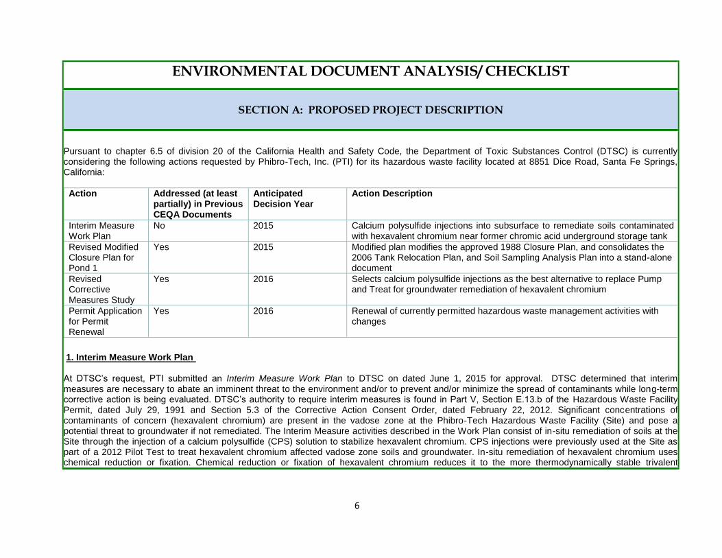
Pursuant to chapter 6.5 of division 20 of the California Health and Safety Code, the Department of Toxic Substances Control (DTSC) is currently considering the following actions requested by Phibro-Tech, Inc. (PTI) for its hazardous waste facility located at 8851 Dice Road, Santa Fe Springs, California:
Action Addressed (at least partially) in Previous CEQA Documents
Anticipated Decision Year
Action Description
Interim Measure Work Plan
No 2015 Calcium polysulfide injections into subsurface to remediate soils contaminated with hexavalent chromium near former chromic acid underground storage tank
Revised Modified Closure Plan for Pond 1
Yes 2015 Modified plan modifies the approved 1988 Closure Plan, and consolidates the 2006 Tank Relocation Plan, and Soil Sampling Analysis Plan into a stand-alone document
Revised Corrective Measures Study
Yes 2016 Selects calcium polysulfide injections as the best alternative to replace Pump and Treat for groundwater remediation of hexavalent chromium
Permit Application for Permit Renewal
Yes 2016 Renewal of currently permitted hazardous waste management activities with changes
1. Interim Measure Work Plan At DTSC’s request, PTI submitted an Interim Measure Work Plan to DTSC on dated June 1, 2015 for approval. DTSC determined that interim measures are necessary to abate an imminent threat to the environment and/or to prevent and/or minimize the spread of contaminants while long-term corrective action is being evaluated. DTSC’s authority to require interim measures is found in Part V, Section E.13.b of the Hazardous Waste Facility Permit, dated July 29, 1991 and Section 5.3 of the Corrective Action Consent Order, dated February 22, 2012. Significant concentrations of contaminants of concern (hexavalent chromium) are present in the vadose zone at the Phibro-Tech Hazardous Waste Facility (Site) and pose a potential threat to groundwater if not remediated. The Interim Measure activities described in the Work Plan consist of in-situ remediation of soils at the Site through the injection of a calcium polysulfide (CPS) solution to stabilize hexavalent chromium. CPS injections were previously used at the Site as part of a 2012 Pilot Test to treat hexavalent chromium affected vadose zone soils and groundwater. In-situ remediation of hexavalent chromium uses chemical reduction or fixation. Chemical reduction or fixation of hexavalent chromium reduces it to the more thermodynamically stable trivalent
7
chromium, which can precipitate or adsorb to soil. A reductant such as CPS can convert the toxic and soluble hexavalent chromium into an insoluble non-toxic hydroxide compound.
12
Interim Measure activities are proposed near the former chromic acid underground storage tank that was removed in or around 1981. The area is adjacent to the Pilot Test injection area, in the alleyway east of Pond 1 in the vicinity of groundwater monitoring wells MW-4 and MW-9. A 45-foot thick target injection zone will extend from approximately 10 to 55 feet below ground surface (bgs) and will be composed of five vadose zone units, including the upper portion of the Hollydale Aquifer. The top layer is fill, which is found at variable depths below the Site. Below the fill is the upper sandy silt unit, sometimes referred to as the Bellflower Aquiclude, which consists of sandy silt with a trace of clay and extends 15 feet bgs. Below the Bellflower Aquiclude is the Gage Aquifer - a fine to coarse grain sand layer with fine gravel lenses that extends to approximately 30 feet bgs. This aquifer has been unsaturated since the groundwater monitoring began in 1985. Below the Gage Aquifer is an unnamed aquitard of silt and clay, which extends to approximately 50 feet bgs. Below the unnamed aquitard is the Hollydale Aquifer, which extends between approximately 50 and 150 feet bgs. While it is typically a fully saturated aquifer, the Hollydale Aquifer is currently unsaturated from the bottom of the unnamed aquitard to a depth of approximately 75 feet bgs due to drought conditions. The top 5 feet of the unsaturated Hollydale Aquifer will be included in the target injection zone. Before advancing borings, a concrete cutting contractor will core concrete and asphalt at all borehole locations. The contractor may clear each borehole to a depth of five feet bgs with a hand auger to check for potential utilities not detected during the utility locating process. The Site Environmental Health and Safety Plan (EHASP) will be modified for proposed tasks. Twenty-five injection boreholes will be advanced adjacent to and in close proximity of the Pilot Test injection area. Borehole locations have been chosen to address distributed impacts from the assumed former chromic acid tank releases. Injection points will be advanced approximately 15-feet on-center within the CPS solution injection area. An 8040-series Geoprobe® truck-mounted, direct-push drill rig or its equivalent will be used to advance small-diameter stainless steel injection rods (a larger rig than used in the Pilot Test). At each target depth, the drive rod will be retracted to expose the five-, two-, or one-foot injection interval of the rod. The injection interval used will vary based on field performance of the injection tooling. The target volume of CPS solution to be injected at each interval will vary based on the stratigraphic unit being targeted. Following injection of the target CPS solution volume into the treatment interval, the injection tooling will be advanced to the next treatment interval. The remaining CPS solution will be injected incrementally such that the whole target zone is treated in a step-wise fashion from top to bottom with approximately equal volumes of CPS solution being injected at each interval of each injection zone. The CPS solution injected into the treatment zone will be mixed to a dosage concentration of 5% by volume. The CPS solution will be injected using a
1 Iris Environmental. Revised Groundwater Corrective Action Pilot Test Work Plan. Phibro-Tech Inc., Santa Fe Springs, California. May 29, 2008.
2 The Centers for Disease Control and Prevention (CDC) prepared an International Chemical Safety Card for Calcium Polysulfide (ICSC # 1038) describing safe
handling requirements; including eye protection, gloves, and respirators, as well as potential risks from exposure to CPS; including irritation to eyes, skin, and respiratory tract. Extreme exposure may result in death. The Occupational, Safety and Health Administration (OSHA) lists CPS as a “hazardous material” under the Federal OHA Hazard Communication Standard, 29 CFR 1910.1200. Upon application, CPS quickly degrades to calcium hydroxide and sulfur. Calcium hydroxide is one of many hydroxides found in food and are generally regarded as safe by the Food and Drug Administration (USEPA, Office of Prevention, Pesticides and Other Toxic Substances. Reregistration Eligibility Decision for Inorganic Polysulfides. List D – Case No. 4054. September 30, 2005.). CPS is not listed as a known or suspected carcinogen (IBID). DTSC has previously approved the use of CPS to treat hexavalent chrome and found it to be safe and effective. Additional information about hexavalent chrome can be found at the EPA website: https://clu-in.org/contaminantfocus/default.focus/sec/chromium_VI/cat/Overview/
8
progressive cavity pump with a flow rate of up to 100 gallons per minute (gpm) and pressure up to approximately 800 psi. To confirm the CPS solution has been distributed throughout the subsurface as expected, a test boring will be advanced shortly after the injection program begins to verify the assumed radius of influence in each geologic unit. Soil test borings will also be advanced after the entire program has been completed to assess evidence of hexavalent chromium fixation. Soil cores from all sampling events will be visually inspected and soil samples will be collected from approximately every five feet of soil core for laboratory analytical testing to confirm the success of the injection. After injection, the boreholes will be grouted with neat cement and bentonite and the surface seal constructed with like materials. The start date for Interim Measure activities will depend on approval of an amendment to the existing Waste Discharge Requirements Permit from the Los Angeles Regional Water Quality Control Board. It is anticipated that obtaining the initial samples to measure existing levels (baseline) of hexavalent chromium in soil samples, CPS solution injection, and process monitoring will take approximately eight weeks, after receiving all agency approvals. Laboratory results for performance monitoring samples of soil will typically be available two weeks following the collection date. Submittal of an Interim Measure Report is anticipated two months following receipt of the last performance monitoring analytical results.
3
2. Revised Modified Pond 1 Closure Plan PTI submitted a Revised Modified Closure Plan for Pond 1 dated September 2015 (Revised Modified Pond 1 Closure Plan) to DTSC for approval.
4 The
Revised Modified Pond 1 Closure Plan updates the earlier Modified Pond 1 Closure Plan approved by US EPA and Department of Health Services (“DHS” and predecessor to DTSC) in 1988. An Initial Study and Negative Declaration (IS/ND) was prepared for the 1988 Modified Pond 1 Closure Plan and certified by DTSC as Lead Agency. Pond 1 was incorporated in the Interim Status Document issued to Southern California Chemical (Predecessor to PTI) in 1980. Pond 1, a former surface impoundment, is located in the northwest portion of the Facility. Pond 1 was constructed in 1975 by modifying a former zinc pond and was used as a surface impoundment for facility waste water between 1975 and 1985. Modifications included relining the pond with a 6-inch thick layer of reinforced concrete and extending the height of the walls. The structure is roughly square, measuring about 37-feet by 37-feet and 3 feet deep with 1 foot below grade and extending two feet above grade. Pond 1 was taken out of service in July 1985 in accordance with an unapproved closure plan in violation of California law. All liquids were removed from Pond 1 and the unit cleaned of any residual wastes. However, this closure plan was not approved by US EPA and California agencies prior to undertaking the closure activities. Additionally, the former Pond 1 structure has been used as a secondary containment structure for two 30,000-gallon wastewater tanks (W-1 and W-2) that are crucial to the continued operation of the Facility. In 2012, DTSC requested that PTI submit a modified closure plan to address new closure regulations, new information regarding facility conditions, the proposed new treatment of groundwater and soil contamination, which could also potentially be appropriate for Pond 1, and that would allow for third-party closure of Pond 1, if required. The Revised Modified Pond 1 Closure Plan was prepared as a result of this request. The Revised Modified Pond 1 Closure plan proposes new and revised details on how Pond 1 will be closed and how any contamination will be detected and cleaned up if found. Such closure activities include the removal of hazardous waste tanks, a filter press, and ancillary equipment, removal of the pond structure, removal of underlying soils and confirmation testing of underlying soils. Additionally, the Revised Modified Pond 1 Closure Plan includes groundwater monitoring
3 Iris Environmental. Interim Measure Work Plan. Phibro-Tech Inc., Santa Fe Springs, California. June 1, 2015
4 “Phibro-Tech, Inc., CAD 008 488 025, Santa Fe Springs, California, TSD Facility, Pond 1 Closure Plan, September 2015, (With Updated Appendices B [figures] and
G)”, dated September 2015, Received December 3, 2015, prepared by Iris Environmental, Submittal Cover Letter dated December 3, 2015.

9
requirements (Article 6), a contingent post-closure plan, and in-situ soil treatment for contamination. The removal and cleanup would involve excavation of the top 10 feet of soil and treatment of the deeper soil using in-situ treatment. The purpose of the in-situ treatment is to reduce the mass of toxic hexavalent chromium in the vadose zone to the nontoxic trivalent chromium. As part of Pond 1 closure, PTI is required to close and remove four hazardous waste tanks (permitted waste water treatment tanks (W-1, W-2) and variance waste water treatment tanks (W-3, W-4) and filter press. Tanks W-1 and W-2 are hazardous waste tanks located within the structure of the pond. Tanks W-3 and W-4 are located adjacent to Pond 1 and must be closed to facilitate closure. The following is a summary of those steps necessary to close Pond 1, which include the closure and removal of tanks W-1 and W-2, and W-3 and W-4, the excavation of soil and in-situ treatment:
Sample and remove waste from tanks W-1, W-2, W-3, and W-4 and pressure wash them with water within a containment area;
Remove and decontaminate any instrumentation on the tanks;
Cut tanks into pieces that can be placed into a 30-cubic yard or 40-cubic yard roll-off bin staged near to the Pond 1 containment basin;
Remove a filter press (PTI is authorized to operate the filter press under a variance)
Collect soil samples beneath the concrete basin;
Remove and dispose of the concrete basin;
Inject calcium polysulfide to soils to a depth of 10 feet;
Excavate soil to a depth of 10 feet below the containment basin;
Inject calcium polysulfide between the depths of 10 and 55 feet;
Backfill excavated area with clean fill and cover with a temporary asphalt cap.5
PTI is required to close Pond 1, and waste water treatment tanks W-3 and W-4, pursuant to the closure requirements found in California Code of Regulations, title 22, division 4.5., Chapter 15. Additionally, PTI is required to close permitted waste water treatment tanks W-1 and W-2 pursuant to closure requirements found in California Code of Regulations, title 22, division 4.5., Chapter 14. A permit modification modifying applicable permit language to incorporate the Revised Modified Pond 1 Closure Plan, and applicable documents will also be available for public review and comment. The Revised Modified Pond 1 Closure Plan proposes that all closure activities are expected to be completed within 180 days of the start of the closure process. 3. Revised Corrective Measures Study (CMS) PTI is required to implement corrective action at the Facility. In 1988, the U.S. EPA and Southern California Chemical (PTI’s predecessor) entered into an Administrative Order on Consent, Docket No. RCRA-09-89-0001 (Consent Agreement). The Consent Agreement required, in part, a RCRA Facility Investigation (RFI) to determine fully the nature and extent of any release of hazardous waste and hazardous constituents at or from the Phibro-Tech Hazardous Waste Facility. The RFI showed that there is soil and groundwater contamination at the Facility. Groundwater present in the uppermost saturated zone beneath the Facility, the Hollydale Aquifer, contained
5 AECOM. Pond 1 Closure Plan. Phibro-Tech, Santa Fe Springs, California. May, 2013 and revised September 2015.
10
elevated concentrations of the following hazardous waste or hazardous constituents of concern: (1) heavy metals, including cadmium, hexavalent chromium, chromium, copper, nickel, and zinc, (2) halogenated volatile organic compounds (VOCs), including tetrachloroethylene (PCE), trichloroethylene (TCE), 1,1-dichloroethane (1,1-DCA) , 1,1-dichloroethene (1,1-DCE), and 1,2,-dichloroethane (1,2-DCA), (3) aromatic VOCs, including benzene, toluene, ethylbenzene and xylenes and (4) chlorides. Soils at the Facility contained elevated concentrations of the following hazardous waste or hazardous constituents of concern: (1) heavy metals, including lead, arsenic, cadmium, hexavalent chromium, chromium, copper, and zinc, (2) halogenated VOC's, including TCE, 1,2-DCA and PCE, (3) aromatic VOC's, including benzene, toluene, ethylbenzene and xylenes, (4) polychlorinated biphenyls (PCB's), (5) petroleum hydrocarbons, including diesel fuel, gasoline and an unidentified heavy hydrocarbon believed to be crude oil, and (6) chlorides. Southern California Chemical was also required to conduct a Corrective Measure Study (CMS) to identify and evaluate alternatives for the corrective action necessary to prevent or mitigate any release of hazardous wastes or hazardous constituents at or from the Facility; and a human health risk assessment to evaluate potential impacts to human health from the soil and groundwater contamination identified at the Facility. Based on the findings of the RFI, CMS, risk assessment and other information, DTSC required PTI to implement corrective measures to address releases from the Facility in a DTSC-initiated Permit Modification (effective August 2, 1995). An IS/ND was prepared for the 1995 Permit Modification and approved by DTSC as Lead Agency on June 30, 1995. The selected corrective measures are summarized in part as follows: pumping and treating contaminated groundwater; quarterly monitoring to track groundwater quality and to identify any new releases should they occur; a soil vapor survey to determine the nature and extent of halogenated VOC contamination; in-situ soil vapor extraction if needed to cleanup soils contaminated with halogenated VOC's; in-situ bioventing to cleanup hydrocarbon contaminated soils in the former underground fuel storage tank area; containment measures to prevent human contact with contaminated soils; berming to contain surface water runoff; vadose zone monitoring to identify contaminant migration in subsurface soils; surface water sampling to measure contaminants in surface water discharged from the Facility; status report on Pond 1 closure; site cover operation, maintenance and inspection; financial assurance for corrective action; notification requirements in the event that a potential or immediate threat to human health or the environment is identified, if a new release of hazardous waste or constituents is discovered, or if new solid waste management units are identified or discovered; and deed restrictions to prevent future residential and other sensitive uses of the property. PTI has implemented some of the required corrective measures. Corrective action measures that have been implemented at the Facility are summarized, and include in part, the following: preparation of a Soil Vapor Survey work plan; soil vapor extraction and bioventing to cleanup soils contaminated with halogenated/non-halogenated VOC's and petroleum hydrocarbons; containment measures to prevent contaminant runoff, accidental spills or tank overfilling from infiltrating into subsurface soils or discharging offsite; quarterly monitoring to track groundwater quality and identify any new releases should they occur; vadose zone monitoring; site cover operation, maintenance and inspection; preparation of a Corrective Action Containment System Report and Corrective Action Site Cover Operation, Maintenance and Inspection Plan; deed notice restricting the property from future residential and other sensitive uses; and financial assurance for corrective action. Upon DTSC’s request, PTI submitted a Site Conceptual Model on March 9, 2005, which in part summarized available data regarding the historical sumps, including location, use, status, and related sampling. The Site Conceptual Model document was approved by DTSC on April 18, 2005. DTSC provided comments on the Corrective Action Vadose Zone Monitoring Work Plan to PTI on August 29, 2006. PTI withdrew the Corrective Action Vadose Zone Monitoring Work Plan because of changes in facility operations and submitted a Sump Management Plan and Vadose Zone Monitoring Work Plan to DTSC on January 29, 2007. DTSC provided comments on October 3, 2007 and PTI provided revisions and response to comments. PTI eliminated most of the facility sumps and retrofitted the remaining sumps with double-wall containment and a leak detection system. PTI has completed further characterization of the Facility. In connection with data gaps regarding groundwater conditions, PTI conducted field work and submitted a Data Gap Field Investigation Report on August 15, 2007 and provided the results of field work on October 24, 2007. DTSC provided comments on the Data Gap Report and Addendum on June 17, 2008.
11
Soil Vapor Extraction: PTI was required to conduct a soil vapor survey to determine the nature and extent of halogenated VOC contamination and to conduct in-situ soil vapor extraction if needed to cleanup soils contaminated with halogenated VOC's. PTI submitted a Soil Vapor Survey (SVS) Work Plan and Bioventing Treatability Study Work Plan for bioventing pilot testing to DTSC on February 16, 1998. Based on DTSC comments, the SVS Work Plan was resubmitted in two phases and approved by DTSC on February 27, 2001. PTI performed the SVS fieldwork and submitted a “Phase 1” report to DTSC on April 16, 2001 and “Phase 2” SVS and SVE Pilot Test Work Plan to DTSC on October 17, 2001. PTI further submitted a Soil Vapor Extraction (SVE) Pilot Test Work Plan to DTSC on October 17, 2001. DTSC approved combining the bioventing and soil vapor extraction pilot tests. PTI submitted a Site Conceptual Model on March 9, 2005, which was approved by DTSC on April 18, 2005, resulting in a third phase of SVS. Upon completion of field work, PTI submitted a Comprehensive Soil Vapor Survey Report and SVE Pilot Test Work Plan to DTSC on September 30, 2005 that presented a work plan for a combined SVE pilot test and included the results of PTI’s soil vapor sampling. DTSC approved the revised work plan and addendums on August 3, 2007 and PTI commenced fieldwork for the SVE Pilot test. On May 8, 2008, PTI submitted a remedial design and implementation package which DTSC conditionally approved on May 29, 2008. PTI constructed the approved SVE and bioventing system and operation commenced on October 6, 2008. On June 23, 2009, PTI submitted a SVE System Start up report. DTSC provided comments on February 17, 2010. The SVE system includes seven extraction wells . Three of the extraction wells were installed as well pairs, with one shallow and one deep well at the same location. The shallow wells were screened, generally, in the Gage Aquifer and the deep wells in the fine-grained soils of the unnamed aquitard. The deep wells were eliminated from the extraction system because they did not meet the extraction well air flow rate criteria during pilot testing. Four additional shallow extraction wells were installed to complete the extraction system. The extraction wells were four-inch diameter and 27.5 to 31.5-feet deep with 10 to 20-foot screens, consisting of polyvinyl chloride (PVC). Eleven soil vapor wells were installed to monitor the chemical concentrations in the soil vapor. Seven of the 11 monitoring wells were nested (one shallow and one deep well in the same location) and four were single point monitoring wells. Each monitoring well was one-inch diameter with 5-foot well screens consisting of PVC. The nested monitoring well depths ranged from 24.5 to 29 feet deep (shallow wells) and 42 to 45 feet deep (deep wells). The nested monitoring well screens ranged between 19.5 and 29 feet (shallow wells) and 36 and 45 feet deep (deep wells). The four single point well screens ranged from 18 to 25 feet deep. Since 2008, the SVE system has removed 13,000 pounds of VOCs from 7 SVE wells. Rebound tests have been completed and the soil gas data is being evaluated. Groundwater Monitoring: PTI is required to conduct groundwater monitoring and groundwater has been monitored at the PTI since 1985. PTI submitted a Groundwater Monitoring Work Plan to DTSC on September 29, 1995. PTI submitted a revised draft Water Quality Sampling and Analysis Plan (WQSAP) to DTSC on November 14, 2005, which was revised, based on DTSC comments on August 18, 2006, and further revised based on DTSC comments on May 18, 2007 and May 22, 2012. DTSC approved the WQSAP on April 14, 2014. Data gaps regarding groundwater conditions resulted in further field work and the installation of new upgradient monitoring wells. PTI submitted a Data Gap Field Investigation Report on August 15, 2007 and provided the results of field work on October 24, 2007. DTSC provided comments on the Data Gap Report and Addendum on June 17, 2008. Based on the results of the field work, DTSC provided comments on the May 18, 2007 draft WQSAP on February 16, 2010 and February 28, 2010. PTI continues to conduct groundwater monitoring. Groundwater Remediation PTI is required to conduct groundwater remediation to cleanup contamination in the Hollydale and other affected aquifers. PTI submitted a Groundwater Remediation Work Plan to DTSC on December 15, 1997 and per DTSC request, PTI submitted a follow up pilot study work plan to DTSC on June 29, 2001. On November 11, 2006, PTI proposed a soil and groundwater injection program. As bench scale testing determined the proposed program feasible, PTI submitted a Groundwater Corrective Action Pilot Test Work Plan on September 28, 2007, and a Revised Groundwater Corrective Action Pilot Test Work Plan on May 29, 2008, which DTSC approved on June 27, 2008. The Regional Water Quality Control Board issued a Waste Discharge

12
Requirement (“WDR”) permit to PTI on November 30, 2009. Following the successful implementation of a 2012 p ilot test to treat hexavalent chromium impacted vadose zone soils and in groundwater using CPS injections, PTI proposed modifying the selected groundwater remedy required in the Permit, as modified by DTSC in 1995. PTI submitted a new Corrective Measures Study Report (CMS), dated December 13, 2013 to DTSC for approval. The purpose of the CMS was to evaluate groundwater remediation alternatives and propose a remedy to replace groundwater treatment selected and required to be implemented in the Permit (pump and treat (P&T). PTI submitted a Revised Corrective Measures Study Report (Revised CMS), dated October 6, 2015. The Revised CMS addressed DTSC comments submitted to PTI on September 5, 2014. In support of PTI’s proposal to modify the selected corrective action groundwater remediation, PTI points to several subsurface investigations that have characterized subsurface soil and groundwater conditions. Concentrations of VOCs in the vadose zone have been reduced by a soil vapor extraction system to below human health risk levels. In addition, remediation technologies have advanced since 1995 and the state of the practice has evolved to include many “in-situ” remediation technologies that effectively and cost-efficiently treat hexavalent chromium and VOCs in soil and groundwater. Groundwater P&T can be effective at controlling further migration of dissolved contaminants in groundwater; however, it is inefficient at remediating impacted groundwater and vadose zone sources, is unsustainable, and is expensive to implement and operate over the long term. Based on the advances in remediation technologies since 1995, coupled with the successful implementation of CPS at the Site, PTI proposed reevaluating and changing the groundwater remedy to injection of CPS for the Site. The Revised CMS evaluated the following four corrective measures alternatives:
No action;
Groundwater pump and treat;
In-situ injection of calcium polysulfide; and,
Zero-valent iron nanoparticle injection.
The Revised CMS recommends in-situ injection of CPS to modify DTSC-selected groundwater remedy and permit conditions. The recommendation is based on the results of the Pilot Study, which has demonstrated that in-situ injection of CPS can reduce the soluble, toxic hexavalent chromium upon contact to non-toxic, non-soluble trivalent form of chromium in the soil and groundwater. The CPS solution would be injected into the vadose zone and groundwater impacted with hexavalent chromium above background concentrations, using specially designed injection tooling mounted to a direct push drill rig. The solution is mixed to a specified weight percent concentration in surface holding tanks and then injected under controlled pressures and flow rates to the target depth through a manifold to single or multiple hoses at once. Groundwater quality will be monitored in accordance with amendment to the existing Waste Discharge Requirements Permit from the Los Angeles Regional Water Quality Control Board. The facility’s ex isting groundwater wells will be monitored during the injection process for changes in groundwater chemistry. Soil samples will be collected before and after injection, while samples of groundwater will be collected before, during and after injection for hexavalent chromium, metals, and VOCs. DTSC is reviewing the Revised CMS. This alternative, if selected, would allow PTI to use in-situ treatment of CPS to remediate contaminated groundwater.
6 DTSC will decide to either adopt the proposed in-situ treatment, adopt it with changes or other alternatives, or reject the proposal. DTSC
will prepare a Statement of Basis summarizing DTSC selected decision. DTSC will provide the public with an opportunity to review and comment on the proposed cleanup alternative.
6 Iris Environmental. Corrective Measures Study Report. Phibro-Tech, Inc. Santa Fe Springs, California. December 13, 2013, Revised October 6, 2015.

13
4. Permit Renewal PTI submitted an application seeking to renew its Hazardous Waste Facility Permit (Permit Application) pursuant to California Health and Safety Code (HSC) Section 25200 (California’s Hazardous Waste Control Act (HWCA), originally adopted in 1972 (HSC Section 25101 et seq., and largely implemented in lieu of the federal Resource Conservation and Recovery Act of 1976). DTSC is reviewing the Permit Application. The Permit Application contains activities previously authorized in the PTI’s Hazardous Waste Facility Permit and new activities. In determining whether to issue the Permit Renewal, DTSC may exercise discretion and impose conditions as provided in HSC Section 25200 et seq. and the implementing code of regulations found in California Code of Regulations (Cal. Code Regs.), title 22, including section 66271.5, subdivision (c)(1)-(4) (Draft Permits). Each permit issued must also include terms and conditions as the Department determines necessary to protect human health and the environment from hazardous waste treatment, storage and disposal related activities. (HSC Section 25200; Cal. Code Regs., title 22, section 66270.32.) DTSC’s discretion in deciding whether to issue and, if so, how to condition issuance of the Permit Renewal is therefore proscribed by statute (i.e., HSC Section 25200 et seq.) and the implementing regulations. PTI currently operates a hazardous waste facility under a Hazardous Waste Facility Permit issued on July 29, 1991 (1991 Permit). An Initial Study and approved a Negative Declaration was certified by DHS which supported the 1991 Permit decision. By operation of law, PTI may continue to operate under the terms of the 1991 Permit until DTSC makes a determination on whether to issue a new permit or deny the Permit Application. PTI owns and operates a hazardous waste facility that stores, treats, and transfers hazardous wastes. Hazardous wastes are shipped to the Facility for treatment from various industries including, but not limited to, the following:
Electronics manufacturing;
chemical manufacturing;
metal finishing; and
aerospace industries.
PTI recovers metals from inorganic waste streams, primarily spent metal plating and stripping etchants. Examples of waste types managed at the PTI Facility include the following:
Alkaline and acidic metal etchants, metal strippers, and metal finishing baths;
Alkaline and acidic materials that include solids, slurries, and other metal-containing materials; and
Other miscellaneous inorganic solutions and solids.
PTI is requesting in Section D of their September 2014 Permit Application to make the following changes to their operations: 1. Construction of New Container Storage Area (CS-) 5 Container Storage area 5 (CS-5) will be a new regulated containment area located between CS-2 and CS-3 and CS-4 and will be primarily used for the storage of containers during loading/unloading trucks. This unit is a bermed, irregular L-shaped area made of reinforced concrete that comprises two areas: an acid area and a base area. The acid area measures 67.45 feet deep and varies in width, with a maximum of 40.1 feet wide at the north end
14
and about 35.25 feet on the southern end. A truncated triangular shaped portion, the base area, is separated by a wall and extends to the west along the south border of CS-2 and is approximately 46.25 feet wide on the south end and changes in depth from about 29.5 feet on the east side to 17.27 feet to the west. The floor of the unit is sloped to follow the grade elevations with the north part being about two inches lower. There will be with a five-inch rollover-berm along the south side height of approximately 5 inches. This height will be maintained on containment walls which means that the height from top of containment wall to floor of containment area will vary from about five to seven inches on the north side. Outer walls of containment areas CS-2 and CS/3/CS-4 will be utilized as they will exceed the required minimum height. From Testing, Inspection & Certification Services Report 14-3-20 the total usable storage area for CS-5 is 2,648 square feet for the acid area and 913 square feet for the base area. This containment area will be concrete and coated with a chemical resistant coating similar to the other containment areas (e.g. Novalac or Corro-Flor). PTI will use the same or similar coating materials when repairs are needed. It is expected that construction of CS-5 will be impacted by the construction efforts to install new wastewater tanks to allow for Pond 1 Closure and that construction would not be completed until up to two years after the new permit effective date. The surficial asphalt/base material of up to six-inched thick, will be removed with a mini-dozer with any the removed material collected in one or more small bins/or roll-off bin(s). It is expected that only the upper layer of asphalt will be removed. If soil is exposed in any area, soil samples will be collected following the methodology in the November 22, 2006 “Revised Draft Pond 1 Soil Sampling and Analysis Plan” which was submitted and approved as part of the 2006 Tank Relocation Plan. Sample depths in the area of the CS-5 are not expected to be collected more than a few feet bgs and would most likely be collected using a hydraulically driven direct push rig mounted to a heavy-duty pick-up truck or small work truck. The foundation for the new CS-5 area will be constructed by fabricating wood and/or cardboard forms, laying down the steel reinforcing, and then pouring concrete using a concrete pumping truck. After the concrete cures, the surface will be prepped and coated with an epoxy coating. 2. Modifications and Expansion of CS-1 Area
7
The Facility is planning to make several modifications to the CS-1 area. The expanded CS-1 area is referred to as CS-1 Ex. Although there will be a net gain in storage area, the planned storage capacity of 69,000 gallons will remain the same. The proposed changes are: Modification A – The existing CS-1 north containment wall will be moved 4 feet south so a that a pedestrian sidewalk can be added between CS-1 Ex and the main plant roadway to allow for improved safety for pedestrians. Modification B – Since Modification A will relocate the north containment wall where the entrance ramp is currently located in the northwest corner, a new ramp will be required. This 15-foot wide entrance ramp will be placed in a new location 33 feet east of the northwest corner of CS-1 Ex. This reduces the containment surface area by about 227 square feet. Modification C – A new 1,500 square feet pad will be added to the southeast corner of the existing CS-1. A berm will be provided to southeast corner of CS-1 extending south 34.66 feet then west 38.96 feet until it intersects with the New J-Containment Area. Along the north end, this will be 47.43 feet. The total containment area will be 3,817.5 square feet. The perimeter containment wall in the expanded area will be 10-inches high. Modification D – A 22 feet by 15 feet roof structure will be installed at a height of 10 feet in the southeast corner of the CS-1 Ex area so that waste materials that may be affected by heat can be shaded from the sun. The roof support will not be attached directly through the CS-1 containment floor or
7 PTI may request authorization from DTSC to complete activities 2, 4, and 9 by submitting a Class II Permit Modification request. (DTSC Letter to Phibro-Tech., Inc.
November 17, 2015).
15
walls. The CS-1 container storage area will be expanded to the south adding 1,500 square feet to the existing area. The expanded area will have a 12-inch wide concrete curb. The area where the expansion will take place is currently a storage area for non-hazardous maintenance and production supplies. The expanded area will be at the same elevation as the existing containment. The entrance to CS-1 Ex will be relocated 33 feet to the east. This entrance will have a rollover berm with an elevation of 10 inches above surrounding grade. The existing rollover berm will be removed and replaced with coated concrete at the same grade as the surrounding containment area. A 10-inch tall curb will be placed in the location of the previous entrance. In addition to the expansion, the section of the north border of the area east of the new entrance will be moved to the south by 4 feet to accommodate a walking path next to the storage area. A 15 feet by 22 feet roof structure will be added to the southeast side of the new area to shade containers which may be more sensitive to heat. During the construction of the CS-1 Ex modifications, there will be short periods of time when containment berms will be disturbed. Along the southeastern corner of the existing CS-1, the containment berm will be removed so the new expansion containment area can be connected into the existing area and the junction made smooth and level and the floor coated as described above. Waste drums will remain in CS-1. During this time, a temporary secondary containment berm will be created by using sandbags and polyethylene sheeting to create a berm of at least the same height as the former containment area wall when waste remains in CS-1. The temporary berm will be in place during any time the containment wall is disturbed until construction of the new area is complete, including the containment wall and protective coating. Core samples will be collected to determine characteristics of soil and disposal and/or treatment methods for any soil that is exposed and/or removed. Soil samples will be taken following the methodology in the November 22, 2006 “Revised Draft Pond 1 Soil Sampling and Analysis Plan” which was submitted and approved as part of the 2006 Tank Relocation Plan. Sample depths in this area are not expected to be collected more than 5 feet bgs and samples would be collected using a hydraulically driven direct push rig mounted to a heavy-duty pick-up truck or small work truck. Existing asphalt and concrete covering in the new expanded area and the existing south curb of CS-1 will be removed. Concrete or asphalt debris and excavated soil will be assumed to be hazardous waste or separately characterized in accordance with California regulations to determine if it is hazardous waste. About 17 cubic yards of soil will be removed in this area. Equipment used will include a gasoline powered concrete/asphalt saw, diesel-powered off-road backhoe/loader (such as a Caterpillar 416) with a demolition ram attachment, diesel-powered off-road skidsteer loader with buckets, diesel-powered off-road mini-excavator with buckets, and diesel-powered end dump trucks. After the containment area is cleared, about 17 cubic yards of clean fill will be brought on site by diesel-powered end dump trucks and compacted. About 6 cubic yards of clean fill will be brought on site for construction of the rollover berm at the new entrance. About 6 cubic yards of soil will be removed when the old rollover berm is removed. Construction of the containment area would involve fabricating wood and/or cardboard forms and installing a rebar mesh. Concrete and concrete reinforcement details will be according to the engineering plans to meet local codes. The concrete will contain #4 rebar or greater. The new concrete will be 8 inches thick. The concrete will be poured directly from the concrete truck or by using a concrete pumping truck. The existing south containment curb of CS-1 will remain intact as long as possible during construction to maintain containment of the area. At the time, that construction requires this curb to be breached, adequate temporary containment structures will be put in place to contain contents stored in the area. Likewise, adequate temporary containment structures will be used when the north curb of the area is removed and relocated 4 feet to the south and when the new entrance to CS-1 is constructed. Equipment used for this work will be diesel-powered off-road reach forklifts, diesel-powered concrete truck, diesel-powered concrete pumps (on road) and concrete vibrators.
16
Concrete curbs will be poured. The curbs will contain #4 rebar or greater and be doweled with rebar to the concrete foundation. The equipment used for this work will be the same as used in pouring the tank foundation described above. After the concrete has cured for at least seven days, the floor and interior walls will be coated with a 100% solids Novalac epoxy lining system (or equal) that is chemically resistant to the types of wastes handled by the facility. A 15 feet by 22 feet roof structure will be added to the south east side of the new area to shade some containers which are more sensitive to heat. The supports of the roof structure will be anchored to pads that are within the containment area but elevated above the liquid containment height. This will eliminate the need to penetrate any containment surfaces with anchors. 3. Construction of New CS-6 Roll-Off Bin Storage Area for Dry Solids It is expected that construction of CS-6 will be impacted by the construction efforts to install new wastewater tanks to allow for Pond 1 Closure and that construction would not be completed until up to two years after the new permit effective date. CS-6 will be a 25 feet by 18 feet area and will be used for the storage of up to two roll-off containers of solid waste (i.e. containing no free liquids as measured by the paint filter test. Dry hazardous waste solids in roll-off bins will include off-site waste and various materials placed in roll-off bins or end-dumps at the Facility. This includes hazardous waste generated by operation of the Facility, excluded recyclable materials (if applicable), and hazardous wastes of the same type that are received in containers and consolidated into a roll-off bin. Dry solid roll-off bins received and/or managed in the Facility may vary in capacity from 10 cubic yards to 40 cubic yards and will be managed in one location, along the fence at the northwest corner of the facility, just north of the Laboratory. This area is out of the heavy traffic area of the Facility. Roll-off bins used on site will be either open top bins that can be covered with a tarp or closeable cover bins. End dump trailers if used, will be covered unless waste is being added or sampled. The maximum storage capacity of this unit is two roll-off bins (each with a capacity of between 20 and 40 cubic yards) with a combined weight of up to 40 tons of hazardous waste. Managed waste types include: dewatered sludge, copper, nickel or other wastes from on-site treatment processes and storage of containers (e.g. supersacks) of off-site hazardous waste. The following is a description of the installation of container storage area CS-6 which will be located in along the north property boundary in the western area of the facility. This will be 25 feet by 18 feet area and will be used for the storage of up to two roll-off containers of solid waste. The area where the new tanks and containment system will be installed is currently an open space with concrete and asphalt covering where production materials (filters, empty drums, spare maintenance parts, etc.) were temporarily placed in the past. Subsurface samples will be obtained in the area of the CS-6 construction to determine characteristics of soil to be removed to facilitate disposal and/or treatment. In addition, the samples may indicate whether additional cleanup by over excavation or other means may be warranted. Soil samples will be collected following the methodology in the November 22, 2006 “Revised Draft Pond 1 Soil Sampling and Analysis Plan” which was submitted and approved as part of the 2006 Tank Relocation Plan. Sample depths in this area are not expected to be collected more than 5 feet bgs and would be collected using a hydraulically driven direct push rig mounted to a heavy-duty pick-up truck or small work truck. Existing asphalt and concrete covering in the area will be removed. Concrete or asphalt debris and excavated soil will be assumed to be hazardous waste or separately characterized in accordance with California regulations to determine if it is hazardous waste. Assuming an excavation depth of 5 feet, about 80 cubic yards of soil will be removed in this area. Equipment used will include a gasoline-powered concrete/asphalt saw, diesel-powered off-road backhoe/loader (such as a Caterpillar 416) with a demolition ram attachment, diesel-powered off-road skidsteer loader with buckets, diesel-powered off-road mini-excavator with buckets, and diesel-powered end dump trucks.

17
Diesel-powered end dump trucks will bring in and compact about 70 cubic yards of clean fill material. Construction of the containment area would involve fabricating wood and/or cardboard forms and installing a rebar mesh. Concrete and concrete reinforcement details will be according to the engineering plans to meet local codes. The concrete will be 8 inches thick and be reinforced with #4 rebar. Concrete will be poured directly from the concrete truck or by using a concrete pumping truck. Equipment used for this work will be diesel-powered, off-road reach forklifts, diesel-powered concrete truck, diesel powered concrete pumps (on road) and concrete vibrators. Five-inch high concrete curbs, nominally six-inches wide will be poured. The curb on the southwest side will be rounded to enable the containers to roll over as they are loaded in this area. The walls will contain #4 rebar or greater and be doweled with rebar to the concrete foundation. The equipment used for this work will be the same as used in pouring the tank foundation described above. This area may not be coated with epoxy because this material would become damaged from the container wheels as they roll across the surface. The concrete in this area will not be exposed to liquid chemical spills so a chemically resistant coating may not be required. The concrete surface will be inspected regularly as specified in the inspection schedule in the Operating Plan. 4. Construction of Tanks W-7 and W-8 in a new location to replace tanks W-1 and W-2, which are currently situated on top of Pond 1.
8
Permit No. 91-3-TS-002, effective July 29, 1991, identifies tanks W-1 and W-2 as wastewater treatment tanks that are each identified in the permit as 30,000 gallons, but as 30,457 gallons in engineering certifications. Effective or operating capacity is less than 30,000 gallons. Because tanks W-1 and W-2 were installed in the concrete-lined area that formerly served as Pond 1, which was identified under the 1981 Interim Status Document, tanks W-1 and W-2 must be relocated to allow access to execute the planned closure of Pond 1 (closure of Pond 1 is proposed under separate approval). PTI requests authorization to install two new tanks W-7 and W-8, each 30,500 gallons, to replace W-1 and W-2. W-7 and W-8 will be placed in a newly constructed secondary containment area just north of the existing Pond 1 that is sized to contain the release of one tank, plus the rainfall from a 25-year/24-hour storm event. Before the containment area for W-7 and W-8 can be constructed, the 75 cubic foot filter press currently identified as filter press FP-#2 will be removed. A new filter press FP-#2A of comparable size will be constructed in a nearby location. This would involve fabricating wood and/or cardboard forms and pouring concrete using a concrete pumping truck for construction of the foundation and then using and a 17 or 23-ton boom truck for placing the filter press components on the foundation. When installation of FP-#2A is complete, FP-#2 will be disassembled and closed, as described in the Part B closure plan (Volume 2) submitted to DTSC in September 2014. This will be considered a partial closure for the filter press and tanks W-1 and W-2. Closure records will be maintained and submitted to DTSC and will also be maintained in facility records so that they can be included in the final facility closure report. Another Filter Press known as Filter Press #1 must also be closed and dismantled in order for the Tanks W-7 and W-8 to be constructed. Filter Press #1 will be closed using procedures in the Facility Closure Plan. It will be dismantled using a 17 or 23-ton boom truck. Filter plates and hydraulic oil will be removed and managed separately as closure wastes. The filter press metal components will be placed on a truck for management as scrap metal or as closure generated waste.
8 PTI may request authorization from DTSC to complete activities 2, 4, and 9 by submitting a Class II Permit Modification request.
18
Existing asphalt, concrete covering, and tank walls in the area of the new tanks W-7 and W-8 will be removed. Concrete or asphalt debris and excavated soil will be assumed to be hazardous waste or separately characterized in accordance with California regulations to determine if it is hazardous waste. Assuming an excavation of up to five feet, about 180 cubic yards of soil will be removed in this area. Equipment used will include a gasoline-powered concrete/asphalt saw, diesel-powered off-road backhoe/loader (such as a Caterpillar 416) with a demolition ram attachment, diesel-powered off-road skidsteer loader with buckets, diesel powered off-road mini-excavator with buckets, and diesel-powered end dump trucks. After the tank and containment area is cleared, about 110 cubic yards of clean fill will be brought on site by diesel-powered end dump trucks and compacted. Construction of the containment area would involve fabricating wood and/or cardboard forms and installing a rebar mesh. Concrete and concrete reinforcement details will be according to the engineering plans to meet local codes. The concrete will contain #4 rebar or greater and be 17 inches thick. The concrete will be poured directly from the concrete truck or by using a concrete pumping truck. The tank pads for Tanks J-6 and J-7 will have radial grooves to allow for inspection and identification of possible leaks at the bottoms of the tanks. Equipment used for this work will be diesel-powered off-road reach forklifts, diesel-powered concrete truck, diesel-powered concrete pumps (on road) and concrete vibrators. Concrete walls will be poured. The walls will be 8 inches thick and reinforced with #4 rebar or greater. Water stops will be installed between the walls and containment pad. The equipment used for this work will be the same as used in pouring the tank foundation described above. After the concrete has cured for at least seven days, the floor and interior walls will be coated with a 100% solids Novalac epoxy lining system (or equal) that is chemically resistant to the types of wastes handled by the facility. New fiberglass reinforced plastic (FRP) tanks will be placed on their designated tank pads using a diesel-powered boom truck. Seismic restraints will be installed on the tanks. Penetrations into the coated tank pad will be repaired and sealed as needed. Tank installation and seismic restraints will be certified by a professional engineer. Tank piping and instrumentation (e.g. level indicators, mixers, etc.) will be installed. 5. Construction of New Tank Containment Area S and Tanks S-8 and S-9 New Containment Area S for the proposed Tanks S-8 and S-9 will be located west of the existing containment area for Tank S-5. This area will be 19.33 feet by 34.33 feet, and will have a minimum containment wall height of 36 inches. The containment area for the two new tanks will be made of reinforced concrete and coated with a 100% solids Novalac epoxy lining system (or equal) that is chemically resistant to the types of wastes handled by the Facility. The eastern containment wall of the S-8/S-9 area will be shared with the western wall of the S-8/S-9 containment wall. The following is a description of the installation of two new tanks (S-8 and S-9) and a containment structure west of existing tank S-5. The existing tank containment will be extended by 34 feet by 19 feet and contain two tanks; each with volume of 12,300 gallons. The area where the new tanks and containment system will be installed is currently an open aisle covered with concrete and asphalt that is used by forklift and foot traffic. Subsurface samples will be obtained in the area of the new S-area to determine characteristics of soil and disposal and/or treatment methods. In addition, the samples may indicate whether additional cleanup by over excavation or other means may be warranted. Soil samples will be collected following the methodology in the November 22, 2006 “Revised Draft Pond 1 Soil Sampling and Analysis Plan” which was submitted and approved as part of the 2006 Tank Relocation Plan. Sample depths in this area are not expected to be collected more than 5 feet bgs and would be collected using a
19
hydraulically driven direct push rig mounted to a heavy-duty pick-up truck or small work truck. Existing asphalt and concrete covering in the 34 feet by 19 feet area of new tank and tank walls will be removed. Concrete or asphalt debris and excavated soil will be assumed to be hazardous waste or separately characterized in accordance with California regulations to determine if it is hazardous waste. Assuming a 5 foot depth of soil removal, about 120 cubic yards of soil will be removed in this area. Equipment used will include a gasoline-powered concrete/asphalt saw, diesel-powered off-road backhoe/loader (such as a Caterpillar 416) with a demolition ram attachment, diesel-powered off-road skidsteer loader with buckets, diesel-powered off-road mini-excavator with buckets, and diesel-powered end dump trucks. After the tank and containment area is cleared, construction of the containment area would commence which involves fabricating wood and/or cardboard forms and installing a rebar mesh. About 80 yards of clean fill will be added. Concrete and concrete reinforcement details will be according to the engineering plans to meet local codes. The concrete will contain #4 rebar or greater. The concrete will be poured directly from the concrete truck or by using a concrete pumping truck. The existing west containment wall for tank S-5 will remain intact as long as possible during construction to maintain containment of the existing tanks. At the time that construction requires this wall to be breached, adequate temporary containment structures will be put in place or tanks taken out of service as needed. The tank pads for S-8 and S-9 will have radial grooves to allow for inspection and identification of possible leaks at the bottoms of the tanks. Equipment used for this work will be diesel-powered off-road reach forklifts, diesel-powered concrete truck, diesel-powered concrete pumps (on road) and concrete vibrators. Concrete walls will be poured. The walls will contain #4 rebar or greater and water stops will be used between the containment floor and the walls. The equipment used for this work will be the same as used in pouring the tank foundation described above. After the concrete has cured for at least seven days, the floor and interior walls will be coated with a 100% solids Novalac epoxy lining system (or equal) that is chemically resistant to the types of wastes handled by the facility. New FRP tanks will be placed on designated tank pads using a 17 or 23- ton diesel-powered boom truck. Seismic restraints will be installed on the tanks. Penetrations into the coated tank pad will be repaired and sealed as needed. Tank installation and seismic restraints will be certified by a professional engineer. Tank piping and instrumentation (e.g. level indicators, mixers, etc.) will be installed. 6. Modifications to Existing Containment Area F Containment Area F is located in the southwest portion of the Facility. There are two tanks that store or treat hazardous waste, F-1 and F-2A contained within Subarea F4. In addition there is a 10-foot diameter open-topped container called the dry basin that collects the solids from F-2A before they are packaged for disposal. The total area within containment walls is about 1,074 square feet. The outer perimeter wall has varying heights as shown on Unit Drawing C10 of 25 to 51 inches. The walls and floors of this containment area are made of reinforced concrete and coated with an impervious fiberglass coating. The following is a description changes to the dimensions of the containment area around regulated hazardous waste tanks F-1 and F-2A. Currently, the containment area includes tanks F-1, F-2A, an air scrubber, and a filter press; the containment area has a square footage of 1,074 square feet.

20
Proposed changes to the containment area are as follows: A new wall will be constructed running east-west feet south of tank F-2A. A wall to the east of tank F-1 will be removed and the containment area will be extended horizontally 12 feet to the east. An opening will be made in the wall to the north of F-1 to allow the containment area to be joined with an adjacent existing containment area (Area C) to the north. In the containment area to the north, a 3-foot tall north-south wall will be constructed to provide enough containment volume to hold the contents of the largest tank (F-1). The air scrubber F-3B will be moved to the contained area north of tank F-1. The filter press will be moved to within a containment area west of Area C. Subsurface samples will be obtained in the excavation area to determine characteristics of soil and disposal and/or treatment methods. In addition, the samples may indicate whether additional cleanup by over excavation or other means may be warranted. Soil samples will be collected following the methodology detailed in the November 22, 2006 “Revised Draft Pond 1 Soil Sampling and Analysis Plan” which was submitted and approved as part of the 2006 Tank Relocation Plan. Sample depths in this area are not expected to be collected more than 5 feet bgs and would be collected using a hydraulically driven direct push rig mounted to a heavy-duty pick-up truck or small work truck. The containment area east of the existing tank containment will be improved by repairing any damage to existing walls and coating the entire surface with a 100% solids Novalac epoxy lining system (or equal) that is chemically resistant to the types of wastes currently permitted to be handled at the facility. A new 3,500 cubic feet per minute (CFM) packed bed air scrubber utilizing a sodium hydroxide scrubbing solution will be installed in the existing containment area north of the tank containment (Area C). This will replace the existing and same sized F-2B scrubber. A new wall will be installed along a north-south line creating a 12 feet by 15 feet containment area (Area D). This containment will be joined with the F-1/F-2A tank containment through an opening in the wall between the two containments. A new wall will be built along an east –west line four feet south of tank F-2A and F-1 which will create the southern boundary of the new containment for tanks F-1 and F-2A. The resulting new containment area for tanks F-1, F-2A and the scrubber will be large enough to contain the contents of the largest tank (F-1). Concrete or asphalt debris and excavated soil will be assumed to be hazardous waste or separately characterized in accordance with California regulations to determine if it is hazardous waste. About 10 cubic yards of soil will be removed in this area. Equipment used will include a gasoline-powered concrete/asphalt saw, diesel-powered off-road backhoe/loader (such as a Caterpillar 416) with a demolition ram attachment, diesel-powered off-road skidsteer loader with buckets, diesel-powered off-road mini-excavator with buckets, and diesel-powered end dump trucks. Construction of the new containment walls would involve fabricating wood and/or cardboard forms and installing a rebar mesh. Concrete and concrete reinforcement details will be according to the engineering plans to meet local codes. Walls will be 8 inches thick. The concrete will contain #4 rebar or greater. The concrete will be poured directly from the concrete truck or by using a concrete pumping truck. Whenever a containment wall needs to be breached, adequate temporary containment structures will be put in place or tanks taken out of service as needed. Equipment used for this work will be diesel-powered off-road reach forklifts, diesel-powered concrete truck, diesel-powered concrete pumps (on road) and concrete vibrators. 7. Construction of new Containment Area O The Containment Area O will be a new containment area dedicated to the processing of oily water streams. The new Containment Area O will be constructed in the southern portion of the property just east of the new J-Area and CS-1 expansion. The new O-area will contain a total of ten tanks plus additional processing equipment described in Sections D10.4 through D10.7. The containment area will be about 64 feet by 64 feet. The outer perimeter
21
wall will have a height of at least 20 inches. A new bulk tank unload area will also be constructed for oily water tanker trucks arriving at the Facility for unloading. The bulk truck unload containment area will be a concrete pad located in the eastern portion of the Facility, south of the scales. The area will be 24 feet (wide) by 70 feet (length) and have a containment berm of at least six inches high. This area may potentially handle any of the waste types that are received in bulk at the Facility. At the end of the unloading area where the tanker truck is located, there will be a two compartment truck wash basin. This will also be concrete with a Novalac epoxy coating (or equal), however this area need not be designed to handle the weight of delivery vehicles. This will be about six feet in length and each of the two basins will be 12 feet wide (24 feet total). This area will be used to collect residues from rinsing the truck. Residues in the area will be pumped to an appropriate on-site tank to be processed. The new O-Area will include a container pumping station located inside the northwest tank containment wall. This will be a metal or fiberglass grate at about the same height as the containment wall so containers can be placed on here by a fork truck from outside the containment area. The container placement area will be 8 feet by 16 feet, with space to hold 8 pallets of drums (32 drums total). The grating will be supported by legs into the containment basin. Therefore, this container pumping station will not displace containment volume for the tanks and the O-containment basin provides full secondary containment for releases from the drums or during the pumping process. The City of Santa Fe Springs 2008 IS/ND analyzed the potential environmental impacts from the construction and operation of this proposed containment area. 8. New W-9 and W-10 Tanks and Containment Area (Construction TBD) The New W-9/W-10 Containment Area is a new containment area that will be placed in the former location of the Variance Tank (W-3 and W-4) Containment Area east and slightly north of Pond 1. This containment area will first require installation and temporary use of two new J Tanks (J-6 and J-7) in the new J containment area until tanks W-3 and W-4 can be removed and a new containment system constructed. Although construction of the New W-9/W-10 Containment Area is a required component of the Permit Reissuance, the two new 30,500-gallon wastewater storage/treatment tanks (W-9 and W-10) designed for placement in this containment area are an optional feature. The containment area will generally be an “L” shape to provide a cut out for access to a groundwater monitoring in this area. The containment area is 37 feet by 30 feet overall with a 6-foot by 9-foot area cut out of the northeast corner where the monitoring well is located. The height of the outer perimeter wall will be at least 36 inches. The walls of New W-9/W-10 Containment Area will be connected to the New W-7/W-8 Containment Area and the old eastern wall of W-7/W-8 Containment Area will be saw cut in the middle and recoated to reduce the height to less than 36 inches. This design is being utilized in case Tank W-9 or W-10 were to have a release, liquid would be able to overtop the W-9/W-10 Containment Area and flow into the W-7/W-8 Containment Area. The walls and floors of the new W- 9/W-10 Containment Area will be made of reinforced concrete and coated with an impervious fiberglass coating that is chemically resistant to the types of wastes and materials anticipated to be handled in the wastewater treatment area. Table D-2 identifies the materials that may be managed in these tanks, as well as the tank capacities. Tanks W-9 and W-10 are optional and will be added when business justifies their need. The estimated capacity for five existing wastewater tanks totaling 94,418 gallons. Adding Tanks W-3 and W-4 at 12,500 gallons each results in total wastewater tank capacity of 119,418 gallons. In the new configuration described above, if W-9 and W-10 are added, there will be a total of 122,000 gallons of wastewater tank capacity (a 2.2% increase).

22
9. Construction of Tanks J-6 and J-7 and containment area in a new location to replace tanks W-3 and W-4, which are currently located adjacent to Pond 1.
9
Tanks W-3 and W-4 are located adjacent to the Pond 1 containment area currently used for W-1 and W-2. Removal of these tanks prior to Pond 1 closure will improve the safety of the closure activities and also enhance the integrity of operations by eliminating a potential concern for the integrity of the W-3/W-4 containment area and tanks should a seismic event or other factors cause the tank containment area to subside. New tanks J-6 and J-7 will be installed in a new J-containment area. J-6 and J-7 tanks will each be 12,500 gallons and contained by a five (5) foot wall. The containment area will have an “L” shape 34.33 feet by 35.19 feet overall with a 10-foot by 15.83 foot area cut out of the north east corner. The area where the new tanks and containment system will be installed is a mostly unused asphalt pad that is occasionally used to store miscellaneous spare parts and materials such as motors, piping, steam, or heating coils. Soil core samples will be obtained to determine characteristics of soil and disposal and/or treatment methods. Soil samples will be collected following the methodology in the November 22, 2006 “Revised Draft Pond 1 Soil Sampling and Analysis Plan” which was submitted and approved as part of the 2006 Tank Relocation Plan. Sample depths in this area are not expected to be collected more than 5 feet bgs and samples would be collected using a hydraulically driven direct push rig mounted to a heavy-duty pick-up truck or small work truck. Existing asphalt and concrete covering in the area of the new tank and tank walls will be removed. Concrete or asphalt debris and excavated soil will be assumed to be hazardous waste or separately characterized in accordance with California regulations to determine if it is hazardous waste. Assuming an excavation of up to five feet, about 180 cubic yards of soil will be removed in this area. Equipment used will include a gasoline-powered concrete/asphalt saw, diesel-powered off-road backhoe/loader (such as a Caterpillar 416) with a demolition ram attachment, diesel-powered off-road skidsteer loader with buckets, diesel-powered off-road mini-excavator with buckets, and diesel-powered end dump trucks. After the tank and containment area is cleared, about 110 cubic yards of clean fill will be brought on site by diesel-powered end dump trucks and compacted. Construction of the containment area would involve fabricating wood and/or cardboard forms and installing a rebar mesh. Concrete and concrete reinforcement details will be according to the engineering plans to meet local codes. The concrete will contain #4 rebar or greater and be 17 inches thick. The concrete will be poured directly from the concrete truck or by using a concrete pumping truck. The tank pads for Tanks J-6 and J-7 will have radial grooves to allow for inspection and identification of possible leaks at the bottoms of the tanks. Equipment used for this work will be diesel-powered off-road reach forklifts, diesel-powered concrete truck, diesel-powered concrete pumps (on road) and concrete vibrators. Concrete walls will be poured. The walls will be 8 inches thick and contain #4 rebar or greater. Water stops will be installed between the walls and containment pad. The equipment used for this work will be the same as used in pouring the tank foundation described above. After the concrete has cured for at least seven days, the floor and interior walls will be coated with a 100% solids Novalac epoxy lining system (or equal) that is chemically resistant to the types of wastes handled by the facility. New FRP tanks will be placed on designated tank pads using a diesel-powered boom truck. Seismic restraints will be installed on the tanks. Penetrations into the coated tank pad will be repaired and sealed as needed. Tank installation and seismic restraints will be certified by a professional engineer.
9 PTI may request authorization from DTSC to complete activities 2, 4, and 9 by submitting a Class II Permit Modification request.
23
Tank piping and instrumentation (e.g. level indicators, mixers, etc.) will be installed. 10. Construction of New J-5 Tank as part of new J Containment Area (Construction TBD) Tank J-5 is an 8,500 gallon wastewater treatment tank to be constructed as part of the new J Containment Area, but at a later date than the construction of Tanks J-6, and J-7. Tank J-5 will be installed following the same procedures as J-6 and J-7. The new J Containment Area should already be in place when Tank J-5 is installed. Tank J-5 will be placed on the designated tank pad using a diesel-powered boom truck. 11. Construction of New C-Area Container Pumping Station A 797 square foot container pumping station will be created within the existing C-area, in the north-central part of the facility just north of tank C-1D and south of the main driveway. The area will be excavated and regraded to provide containment capacity of 763 gallons plus 4.5 inches of rain. Subsurface samples will be obtained in the area to determine characteristics of soil to be removed to facilitate disposal and/or treatment. In addition, the samples may indicate whether additional cleanup by over excavation or other means may be warranted. Soil samples will be collected following the methodology in the November 22, 2006 “Revised Draft Pond 1 Soil Sampling and Analysis Plan” which was submitted and approved as part of the 2006 Tank Relocation Plan. Sample depths in this area are not expected to be collected more than 5 feet bgs and would be collected using a hydraulically driven direct push rig mounted to a heavy-duty pick-up truck or small work truck. Existing asphalt and concrete covering will be removed. Concrete or asphalt debris and excavated soil will be assumed to be hazardous waste or separately characterized in accordance with California regulations to determine if it is a hazardous waste. Assuming 5 feet of excavation about 180 cubic yards of soil will be removed in this area. Equipment used will include a gasoline-powered concrete/asphalt saw, diesel-powered off-road backhoe/loader (such as a Caterpillar 416) with a demolition ram attachment, diesel-powered off-road skidsteer loader with buckets, diesel-powered off-road mini-excavator with buckets, and diesel-powered end dump trucks. After the area is cleared, about 125 cubic yards of clean fill will be brought on site by diesel-powered end dump trucks and compacted. The new area will be lower in elevation than the existing surface to provide for adequate containment. Construction of the containment area would involve fabricating wood and/or cardboard forms and installing a rebar mesh. Concrete and concrete reinforcement details will be according to the engineering plans to meet local codes. The concrete will contain #4 rebar or greater and be 8 inches thick. The concrete will be poured directly from the concrete truck or by using a concrete pumping truck. Equipment used for this work will be diesel-powered off-road reach forklifts, diesel-powered concrete truck, diesel-powered concrete pumps (on road) and concrete vibrators. Concrete walls will be poured. The height of the walls above the finished surface will vary and are described in the engineering report “Design of Containment for Storage Area Adjacent to C Tanks Located at the South End of the Phibro Tech Facility in Santa Fe Springs, CA.“ The walls will contain #4 rebar or greater and be doweled with rebar to the concrete foundation. Water stops will be installed between the curbs and the floor. The equipment used for this work will be the same as used in pouring the tank foundation described above. After the concrete has cured for at least seven days, the floor and interior walls will be coated with a 100% solids Novalac epoxy lining system (or equal) that is chemically resistant to the types of wastes handled by the facility. 12. Construction of New S-Area Container Pumping Station
24
A new 25 feet by 5 feet concrete area with 10-inch curbs will be created just north of the new Tank S-8/S-9 containment basin. Fiberglass grating will be secured permanently over the curbs to support the drums or totes to be pumped. The container pumping station can hold up to seven tote bins of hazardous waste. Core samples will be obtained to determine characteristics of soil and disposal and/or treatment methods. Soil samples will be collected following the methodology in the November 22, 2006 “Revised Draft Pond 1 Soil Sampling and Analysis Plan”. Existing covering in area of the new curbs will be removed. Disposal of concrete/soil asphalt will be according to regulations depending on analysis of soil removed in this area. It is assumed that soil will be removed to a depth of five feet resulting in about 30 cubic yards of soil removal. Equipment used will include a concrete/asphalt saw (off road), backhoe with a breaker and buckets (off road), skidsteer with buckets (off road, mini-excavator with buckets (off road) and dump trucks (on road). The containment pad and curb will be poured as a monolithic structure. Concrete and concrete reinforcement details will be in accordance with the engineering plans to meet local codes. The concrete will contain #4 rebar or greater. Equipment used for this work will be reach forklifts (off road), concrete truck (on road), concrete pumps (on road) and concrete vibrators (off road). The floor and interior curbs will be coated with a 100% solids Novalac epoxy lining system (or equal) that is chemically resistant to the types of wastes handled by the facility. The area will be given the required amount of cure time. 13. Construction of New W-9/W-10 Container Pumping Station A new 32 feet by 5 feet concrete area with 10-inch curbs will be created just east of the new Tank W-9/W-10 containment basin. Fiberglass grating will be secured permanently over the curbs to support the drums or totes to be pumped. The container pumping station can hold up to nine tote bins of hazardous waste. Core samples will be obtained to determine characteristics of soil and disposal and/or treatment methods. Soil samples will be collected following the methodology in the November 22, 2006 “Revised Draft Pond 1 Soil Sampling and Analysis Plan”. Existing covering in area of the new curbs will be removed. Disposal of concrete/soil asphalt will be according to regulations depending on analysis of soil removed in this area. It is assumed that soil will be excavated to a depth of five feet resulting in removal of about 30 cubic yards of soil. Equipment used will include a concrete/asphalt saw (off road), backhoe with a breaker and buckets (off road), skidsteer with buckets (off road, mini-excavator with buckets (off road) and dump trucks (on road). The containment pad and curb will be poured as a monolithic structure. Concrete and concrete reinforcement details will be in accordance with the engineering plans to meet local codes. The concrete will contain #4 rebar or greater. Equipment used for this work will be reach forklifts (off road), concrete truck (on road), concrete pumps (on road) and concrete vibrators (off road). The floor and interior curbs will be coated with a 100% solids Novalac epoxy lining system (or equal) that is chemically resistant to the types of wastes handled by the facility. The area will be given the required amount of cure time.
25
14. Construction of New W-7/W-8 Container Pumping Station After the new W-7/W-8 Containment Area is constructed, a new 25 feet by 5 feet concrete area with 10-inch curbs will be created just west of the new Tank W-7/W-8 containment basin. Fiberglass grating will be secured permanently over the curbs to support the drums or totes to be pumped. The container pumping station can hold up to seven tote bins of hazardous waste. Core samples will be obtained to determine characteristics of soil and disposal and/or treatment methods. Soil samples will be collected following the methodology in the November 22, 2006 “Revised Draft Pond 1 Soil Sampling and Analysis Plan”. Existing covering in area of the new curbs will be removed. Disposal of concrete/soil asphalt will be according to regulations depending on analysis of soil. It is assumed that soil will be removed to a depth of five feet resulting in excavation of about 25 cubic yards of soil. Equipment used will include a concrete/asphalt saw (off-road), backhoe with a breaker and buckets (off-road), skidsteer with buckets (off-road, mini-excavator with buckets (off-road) and dump trucks (on road). The containment pad and curb will be poured as a monolithic structure. Concrete and concrete reinforcement details will be according to the engineering plans to meet local codes. The concrete will contain #4 rebar or greater. Equipment used for this work will be reach forklifts (off-road), concrete truck (on road), concrete pumps (on road) and concrete vibrators (off-road). The floor and interior curbs will be coated with a 100% solids Novalac epoxy lining system (or equal) that is chemically resistant to the types of wastes handled by the facility. The area will be given the required amount of cure time. 15. Additional changes to current operation that do not require any construction A. The following existing tanks have historically been used at the facility and will be converted from hazardous material service to hazardous waste service without changing existing treatment processes or increasing the total capacity of the treatment processes:
C-40 – located in C-Containment Area, contains potentially hazardous decant water from the copper oxide treatment process;
C-1, C-2, and C-3 – located in C-Containment Pad (West Area); contain ammonium chloride solution that results from scrubbing ammonia vapor
evolved in the copper oxide process in a hydrochloric acid scrubber permitted by South Coast Air Quality Management District (SCAQMD);
S-2 and S-4 – located in S-Containment Area, currently contain virgin copper sulfate, but will be designated to also allow for the capability to
manage hazardous wastes of similar chemical composition;
S-7 – located in the S-Containment Area, is designed to hold virgin copper sulfate for special process subsequently not implemented; currently
mostly unused, but will also be designated to also allow for the capability to manage hazardous wastes of similar chemical composition.
B. Change in status of two current hazardous material product drum storage areas (CS-3 and CS-4) to be regulated as hazardous waste drum storage areas. This would allow hazardous waste drums to be stored in four areas rather than two, but would not increase the number of hazardous waste drums that may be stored at the facility. Expansion of the Site The site footprint will remain unchanged and none of the actions described in detail above, will expand the existing footprint of the facility beyond the

26
current parcel boundaries, increase the amount of impervious surface, or reduce any natural habitat. Other Known, Current, or Probable Projects Occurring Within One Mile and Not Under DTSC Oversight
10
1. PROJECT NAME: Altamar Warehouse DESCRIPTION: The Chalmers Equity Group has proposed to construct a 63,458 square foot warehouse on a 2.92-acre site located at 12140 Altamar Place within the City of Santa Fe Springs. The facility will dedicate approximately 55,266 square feet to warehousing; 5,140 square feet to office use; and 3,052 square feet to office mezzanine. In addition, 99 parking stalls, a bike rack, eight dock high loading doors, two grade-level truck doors, and a 1,064 square foot trash enclosure will be provided. Lastly, approximately 10,191 square feet will be dedicated for landscaping. The Altamar Warehouse is located approximately 1,450 feet to the southeast of the PhibroTech Facility. The most direct access between the two facilities is along Dice Road. CEQA: Mitigated Negative Declaration - 6/17/2015 2. PROJECT NAME: Universal Waste Systems, Inc., Material Recovery Facility and Transfer Station DESCRIPTION: Evaluates the environmental impacts associated with the operation of a new Material Recovery Facility (MRF) and Transfer Station (TS) in the City of Santa Fe Springs. The proposed project is a request by Universal Waste Systems, Inc. (UWS), to obtain a Conditional Use Permit (CUP) to operate a MRF and TS at their existing collection truck storage and repair facility located at 9016 Norwalk Boulevard. Other discretionary approvals will include a Design Development Plan Approval (DPA), a Modification of Property Development Standards, and a Tentative Parcel Map (TPM). The proposed project, if approved, will provide a full range of solid waste processing and recycling activities within the project site. Although the UWS site is less than 200 feet west of the Phibro Tech Facility, there is no direct road access between the properties. The properties are situated on opposite sides of the rail spur line and public access is not provided between the properties. CEQA: Mitigated Negative Declaration – 5/26/2015 3. PROJECT NAME: Burke Street Industrial Complex DESCRIPTION: A largely single-story structure concrete tilt-up structure will be constructed within that portion of the project site located at 11770 Burke Street near the corner of Dice Road and Burke Street. The total floor area of the proposed new building will be 79,252 square feet. The majority of the new building will be devoted to warehouse-related uses. A total of 70,088 square feet of floor area will be devoted to warehouse uses. A total of 9,165 square feet will consist of office uses. The office areas will include a ground level and a mezzanine level located in the new building’s northeast corner. The ground level office area will consist of 4,875 square feet while the mezzanine level will consist of 4,289 square feet. A total of seven dock-high loading docks will be located on the building’s southwest corner.
10
City of Santa Fe Springs. http://www.santafesprings.org/cityhall/planning/planning/environmental_documents.asp
27
Access to the site will be provided by three driveways including two existing located along the Dice Road frontage. Truck and general vehicular access will be provided by a new driveway connection with Burke Street and an existing drive on Dice Road. A third driveway connection with Dice Road will provide access to parking area located along the Dice Road frontage. The driveway widths will be 30-feet. An internal drive-aisle will extend along the site’s west and south sides. This drive-aisle will provide access to a second parking area, located in the project site’s southwest corner, and the loading docks. A total of 157 parking spaces will be provided. Of this total, 107 spaces will be standard stalls, six spaces will be ADA accessible, and 44 spaces will be compact spaces. An internal drive-aisle will extend along the west and south sides of the site. This drive-aisle will provide access to a second parking area, located in the project site’s southwest corner, and the loading docks. Landscaping will be provided along the Burke Street and Dice Road frontages. Additional landscaping will be provided along the site perimeter and along the east-facing elevation of the new building. Perimeter and interior landscaping will total 34,864 square feet. The Burke Street Industrial Complex is located approximately 1,100 feet north of PhibroTech along Dice Road. CEQA: Mitigated Negative Declaration – 5/12/2015 4. PROJECT: Concrete building approved for construction at 11904 Washington Blvd, 58,000 sq. ft. in April 2015
11
5. PROJECT: Project at the Intersection of Altamar Plaza and Dice Road. Currently, waiting for details from City of Santa Fe Springs.
12
Other Known Active DTSC Clean-up Projects Within 1 Mile of PTI
13
1. Angeles Chemical Company, Inc. - 8915 Sorensen Avenue 2. Foss Plating Company - 8140 Secura Way 3. McKesson Chemical Company - 9005 Sorensen Avenue 4. Productol, Inc. - 10051 Romandel Avenue 5. Associated Plating Company - 9636 Ann Street
11
Wayne Morrell, Santa Fe Springs City Planner, telephone conversation, 6/26/2015. 12
Wayne Morrell, Santa Fe Springs City Planner, telephone conversation, 6/26/2015. 13
http://www.envirostor.dtsc.ca.gov/public/search.asp?page=1&cmd=search&business_name=&main_street_name=&city=SANTA+FE+SPRINGS&zip=&county=&status=&branch=&site_type=&npl=&funding=&reporttitle=PROJECT+SEARCH+RESULTS&reporttype=&federal_superfund=True&state_response=True&voluntary_cleanup=True&school_cleanup=True&operating=True&post_closure=True&non_operating=True&corrective_action=True&tiered_permit=True&evaluation=True&spec_prog=&national_priority_list=&senate=&congress=&assembly=&critical_pol=&business_type=&case_type=&searchtype=&hwmp_site_type=&cleanup_type=&ocieerp=False&hwmp=False&permitted=&pc_permitted=&inspections=True&complaints=&orderby=status_description

28
SECTION B: PROJECT BACKGROUND
This section provides a description of previous permit decisions and authorized activities including any permit modifications or corrective action, date(s) of approval(s) and also identifies the CEQA documents (i.e., certified Environmental Impact Report, approved adopted Negative Declaration, Notice of Exemption) prepared. The CEQA document title, name of lead agency, date of certification or approval, and State Clearinghouse (SCH) number are also provided. On September 22, 1988, the Department of Health Services (DTSC’s predecessor) and U.S. EPA approved a Modified Closure Plan for Pond 1. The 1988 Modified Closure Plan activities include removal and relocation of the wastewater tanks, site characterization, removal of the concrete liner and some of the underlying soils and closure as a land disposal unit in accordance with 40 CFR 265. 228. The Department prepared an IS/ND for this project (Subject Title: Southern California Chemical Co. (Pond NO. 1), SCH# 1988072715).
14
On June 19, 1991, DTSC, then known as the Department of Health Services, approved a Hazardous Waste Treatment and Storage permit for Entech Recovery Inc. aka Sothern California Chemical (PTI’s predecessors). The Hazardous Waste Facility Permit has an expiration date of July 29, 1996. By operation of law, PTI may continue to operate under the terms of the 1991 Permit until DTSC makes a determination on whether to issue a new permit or deny the Permit Application. The Department prepared an IS/ND in 1990 (SCH# 1990011026) for this project.
15
On June 30, 1995, DTSC approved a DTSC-initiated permit modification to select required corrective measures to be implemented at the PTI Facility. The permit modification required PTI to implement corrective measures to address releases from the Facility. As discussed previously, required corrective measures included the following:
• Groundwater remediation: pumping and treating contaminated groundwater, • Groundwater monitoring: quarterly monitoring to track groundwater quality and identify any new releases should they occur, • Soil Vapor: a soil vapor survey to determine the nature and extent of halogenated VOC contamination, • In-situ soil vapor extraction if needed to clean up soils contaminated with halogenated VOCs, • In-situ bioventing to clean up hydrocarbon contaminated soils in the former underground fuel storage tank area, • Containment measures to contain surface water runoff, • Vadose zone monitoring to identify contaminant migration in subsurface soils, • Surface sampling to measure contaminants in surface water discharged from the Facility and • Deed restrictions to prevent future residential and other sensitive uses of the property.
16
DTSC prepared an Initial Study and Negative Declaration (SCH# 1994111022), for this project.
14
Department of Health Services. RCRA Closure Plan for Southern California Chemical – Approval Letter, September 22, 1988. 15
United States Environmental Protection Agency. Permit for a Hazardous Waste Management Facility – Entech Recovery Inc. a.k.a. Southern California Chemical. May 29, 1991. 16
Department of Toxic Substances Control. Order Denying Petition for Review for Permit Modification Determination for Phibro-Tech Inc. September 5, 1997.
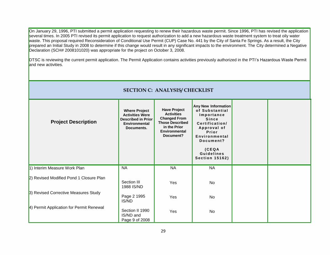
29
On January 29, 1996, PTI submitted a permit application requesting to renew their hazardous waste permit. Since 1996, PTI has revised the application several times. In 2005 PTI revised its permit application to request authorization to add a new hazardous waste treatment system to treat oily water waste. This proposal required Reconsideration of Conditional Use Permit (CUP) Case No. 441 by the City of Santa Fe Springs. As a result, the City prepared an Initial Study in 2008 to determine if this change would result in any significant impacts to the environment. The City determined a Negative Declaration (SCH# 2008101020) was appropriate for the project on October 3, 2008. DTSC is reviewing the current permit application. The Permit Application contains activities previously authorized in the PTI’s Hazardous Waste Permit and new activities.
SECTION C: ANALYSIS/ CHECKLIST
Project Description
Where Project Activities Were
Described in Prior Environmental
Documents.
Have Project Activities
Changed From Those Described
in the Prior Environmental
Document?
Any New Information
o f S ub s ta n t i a l I m p o r t a nc e
S i n ce C e r t i f i c a t i on / Ap p r o va l o f
P r i o r E n v i r o n me n ta l
D o c um e nt ?
( C E Q A G u i d e l i ne s
S e c t i o n 1 51 62 )
1) Interim Measure Work Plan
2) Revised Modified Pond 1 Closure Plan
3) Revised Corrective Measures Study
4) Permit Application for Permit Renewal
NA Section III 1988 IS/ND Page 2 1995 IS/ND Section II 1990 IS/ND and Page 9 of 2008
NA
Yes
Yes
Yes
NA
No
No
No
30
IS/ND Discussion:
This section provides information that supports the responses to each column described above by comparing the information contained in the prior Environmental Impact Report or Negative Declaration and other applicable documents with that existing at the time the current Project determination is being considered. This summary constitutes the baseline conditions that are used to determine the significance of potential Project impacts described in the Environmental Resource section that follows.
Current Baseline Information The earlier environmental documents considered baseline conditions at the time of analysis; one of the purposes of the EDA form is to bring these baseline conditions into the present. The information presented below provides the current baseline conditions. -The Facility is located at 8851 Dice Road in Santa Fe Springs. The entire Facility is paved, except for minimal perimeter landscape vegetation along Dice Road. -The Facility and surrounding buildings are located in an area zoned as M-2, Heavy Manufacturing by the City of Santa Fe Springs. The surrounding area is highly developed and does not provide more than a minimal amount of natural vegetation or habitat. -The nearest residential area is located approximately 550 feet to the north of the Facility along Burke Street. The Kingdom Hall of Jehovah’s Witnesses is also located along Burke Street adjacent to this residential area. - The nearest schools are Aeolian Elementary (0.30 miles), Los Nietos Middle (0.35 miles). Another possible school - Our Lady of Perpetual Help (0.26 miles) is located at the corner of Orange street and Walnut street. The type and current operating status of this school is unknown. St. Paul Catholic High School is located 0.70 miles east of PhibroTech along Santa Fe Springs Road.
- The California Department of Transportation (Caltrans) identifies that closest Officially Designated State Scenic Highway as State Route 2 (SR-2) from the City of La Canada-Flintridge north to the San Bernardino County line. In Los Angeles County, Interstate 110 (I-110) (Arroyo Seco Historic Parkway) between milepost 25.7 and milepost 31.9 is identified by Caltrans as a Historic Parkway. Both of these highways are located more than 10 miles north and northwest, respectively, of the Project site. There is a railroad storage yard located 0.23 miles to the east of Phibro-Tech across Sorensen Avenue and another 0.40 miles to the west across Los Nietos Road.
- The Project site is located in the South Coast Air Basin (Air Basin) within the jurisdiction of the SCAQMD. - The closest public park facility to the Project site is Los Nietos Park, which is located approximately 0.70 mile southwest of the site. A building, operated by Johnson and Wilshire Inc. was constructed near the corner of Burke Street and Norwalk Blvd. This building was constructed sometime between 2010 and 2011 after the last CEQA document for PTI was completed in 2008. In addition, a building at the intersection of Burke

31
Street and Dice Road was demolished in 2011. The site is currently vacant and City of Santa Fe Springs Planning Department staff did not indicate that plans to redevelop the site have been filed with the City.
17
DTSC has determined that there is new information concerning the baseline environmental settings and physical and regulatory conditions since approval of prior environmental document(s); however, such information would not result in any of the conditions described in CEQA Guidelines section 15162 or 15163 that would require preparation of a subsequent or supplemental negative declaration or EIR. As documented in the environmental resource analysis provided below, DTSC has determined that the new information is limited to the following environmental resource areas and that the impact levels for each of the environmental resource areas remains less than significant or as having no impact:
• Air Quality: Addition of air emission estimates for workers and import of fill material to make the analyses from the various analyses consistent; • Greenhouse gas (GHG) Emissions: Addition of GHG emissions as an environmental resource issue area for activities evaluated prior to 2008;
and • Cumulative Effects Analysis: Addition of a cumulative effects analysis to ensure that reasonably foreseeable project(s) would not, in total, result
in any significant environmental affect. References
California Department of Transportation. California Scenic Mapping System. http://www.dot.ca.gov/hq/LandArch/16_livability/scenic_highways/index.htm. Last Updated on 9/2/2011. Accessed 9/2015.
DUDEK. Environmental Information Form. Phibro-Tech, Santa Fe Springs, California. May 29, 2015
Environmental Resource
Where Impact Was Analyzed in
Prior Environmental
Documents.
Do Proposed Changes Involve New Significant
Impacts or Substantially More Severe
Impacts?
[CEQA Guidelines
Section 15162(a)(1)]
Any New Circumstances Involving New
Significant Impacts or Substantially
More Severe Impacts?
[CEQA Guidelines
Section 15162(a)(2)]
Any New Information Requiring
New Analysis or
Verification?
[CEQA Guidelines
Section 15162(a)(3)(A-
D)]
Prior Environmental Documents Mitigations
Implemented or Address Effects?
1. AESTHETICS. Would the project: 1Interim Measure Work Plan 2. Revised Modified Pond 1 Closure Plan - 1988 IS/ND
17
Wayne Morrell, Santa Fe Springs City Planner, telephone conversation, 6/26/2015.
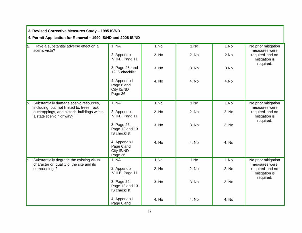
32
3. Revised Corrective Measures Study – 1995 IS/ND 4. Permit Application for Renewal – 1990 IS/ND and 2008 IS/ND
a. Have a substantial adverse effect on a scenic vista?
1. NA 2. Appendix VIII-B, Page 11 3. Page 26, and 12 IS checklist 4. Appendix I Page 6 and City IS/ND Page 36
1.No
2. No
3. No
4. No
1.No
2. No
3. No
4. No
1.No
2.No
3.No
4.No
No prior mitigation measures were required and no
mitigation is required.
b. Substantially damage scenic resources, including, but not limited to, trees, rock outcroppings, and historic buildings within a state scenic highway?
1. NA 2. Appendix VIII-B, Page 11 3. Page 26, Page 12 and 13 IS checklist 4. Appendix I Page 6 and City IS/ND Page 36
1.No
2. No
3. No
4. No
1.No
2. No
3. No
4. No
1.No
2. No
3. No
4. No
No prior mitigation measures were required and no
mitigation is required.
c. Substantially degrade the existing visual character or quality of the site and its surroundings?
1. NA 2. Appendix VIII-B, Page 11 3. Page 26, Page 12 and 13 IS checklist 4. Appendix I Page 6 and
1.No
2. No
3. No
4. No
1.No
2. No
3. No
4. No
1.No
2. No
3. No
4. No
No prior mitigation measures were required and no
mitigation is required.

33
City IS/ND Page 36
d. Create a new source of substantial light or glare which would adversely affect day or nighttime views in the area?
1. NA 2. NA 3. Page 12 IS checklist 4.NA, and City IS/ND Page 37
1. No
2. No
3. No
4. No
1. No
2. No
3. No
4. No
1. No
2. No
3. No
4. No
No prior mitigation measures were required and no
mitigation is required.
Discussion:
1 (a-d). The potential environmental impacts from the project activities proposed in the June 2015 Interim Measure Work Plan were not evaluated in a previous CEQA document. The Interim Measure activities described in the Work Plan consist of In-situ remediation of Site soils through the injection of a CPS solution to stabilize hexavalent chromium. CPS injections were previously used at the facility as part of a 2012 Pilot Test to treat hexavalent chromium impacted vadose zone soils and groundwater. In-situ remediation of hexavalent chromium uses chemical reduction or fixation. Chemical reduction or fixation of hexavalent chromium reduces it to the more thermodynamically stable trivalent chromium, which can precipitate or adsorb to soil. A reductant such as CPS can convert the toxic and soluble hexavalent chromium into an insoluble non-toxic hydroxide compound.
To treat hexavalent chromium in vadose zone soils, 25 injection boreholes will be advanced to expand the Pilot Test injection area, which is onsite near the center of the facility property. An 8040-series Geoprobe® truck-mounted, direct-push drill rig or equivalent will be used to advance the small diameter stainless steel injection rods. It is anticipated that the baseline sampling, CPS solution injection, and process monitoring will take approximately eight weeks after all agency approvals.
The project activities are temporary and would take place on the facility property, which is currently utilized for a variety of hazardous waste management operations and in an area zoned M-2, Heavy Manufacturing. The truck mounted drill rig and additional equipment involved would have no effect on the existing character and visual quality of the site or the surrounding area. Therefore, there will be no significant impacts to any scenic vista or resources. Project activities are anticipated to occur only during the day. Thus, an increase in the overall level of lighting at the site is not expected and therefore, no adverse effects to day or nighttime views would occur in the area.
2 (a-d). The general closure procedures for Pond 1 as written in the 1988 Closure Plan are as follows:
Site Characterization/Tank Relocation Plan
Impoundment Characterization
Concrete and Soil Removal, Soil stabilization
Interim Cover/FinaI Cover

34
Closure certification
Post-Closure Care & Maintenance
Along with the 1988 Modified Pond 1 Closure Plan, DTSC (then known as Department of Health Services) prepared and circulated to the public an IS/ND. This document addressed the environmental impacts from these activities and concluded that the closure would not result in the obstruction of any scenic vista or view open to the public, or result in the creation of an aesthetically offensive site open to public view.
The Revised Modified Pond 1 Closure Plan submitted in 2015, as requested by DTSC, contains many of the same activities. However, it provides more detail, proposes the removal of soil specifically down to 10 feet beneath Pond 1, adds the removal of wastewater treatment tanks W-3 and W-4, adds the injection of calcium polysulfide (CPS) as an in-situ treatment of hexavalent chromium contaminated soils below 10 feet, and is prepared to allow for third-party closure of Pond 1, if required.
The modifications to the 1988 Modified Pond 1 Closure Plan will not result in any significant impacts to any scenic vista or resources in the surrounding area, nor will they substantially degrade the existing visual character or quality of the site and its surroundings . The in-situ remediation of soils will be completed in a similar manner as proposed in the Interim Measure Work Plan. All closure activities will be completed within 180 days and not substantially change the industrial nature of the site and the immediately surrounding area, which is zoned M-2, Heavy Manufacturing. Project activities are anticipated to occur only during the day. Thus, an increase in the overall level of lighting at the site is not expected and therefore, no adverse effects to day or nighttime views would occur in the area.
3(a-d). The purpose of the Revised Corrective Measures Study is to evaluate groundwater remediation alternatives and propose a remedy to replace groundwater pump and treat (P&T), the remedy required in the Permit as modified by DTSC in 1995. DTSC completed an Initial Study and Negative Declaration in 1994 in support of this permit modification decision. In the 1994 IS/ND, it was concluded that no aesthetic impact would result from the project and no mitigation measures were required. Changing the corrective action requirements for groundwater at the facility from P&T to in-situ treatment using CPS would not change the visual context of the site from the surrounding community and would not cause any new impacts to scenic resources or the visual character of the site or surrounding area. The P&T equipment would be similar in nature to the equipment involved with CPS injections and no increase in the overall level of lighting at the site is expected.
4(a-d). PTI submitted a permit renewal application to DTSC, which is still under review. The application proposes a variety of changes to the current hazardous waste management operations at the Facility (see project description above). Some of those changes involve the addition of several new tanks to be constructed onsite. The most significant change proposed is the construction and operation of a new treatment system to treat oily wastewater. The potential environmental impacts from this proposal were evaluated in an Initial Study completed by the City of Santa Fe Springs in 2008. That Initial Study concluded that there would be no new sources of light that would affect nighttime views, no significant impacts to any scenic vista or resources, nor would there any significant impacts to the visual character of the site or surrounding area.
DTSC completed an IS/ND in 1991, which evaluated the potential environmental impacts from the majority of the current hazardous waste management operations at PTI. DTSC concluded that the operations would not result in the obstruction of any scenic vista or view open to the public, or result in the creation of an aesthetically offensive site open to public view. This document did not consider any sources of substantial light or glare, which would

35
adversely affect day or nighttime views in the area. However, the Environmental Information Form submitted by PTI stated that “Nighttime exterior
lighting is currently provided on the Project site for safety and security purposes. Consistent with Santa Fe Springs Municipal Code Sections 155.415
and 155.432, lighting used on the Project site is shielded, hooded, and/or directed onsite in order to minimize light trespass onto adjacent properties.”
Further, in the City of Santa Fe Springs 2008 Initial Study, the following was concluded:
“Given that the subject site is currently developed with an inorganic chemical manufacturing and recycling facility, some existing lighting is already in place. If additional lighting is required for project, both Planning and Police Service staff will review the new lighting plan to ensure it meets Santa Fe Springs Municipal Code Sections 155.415 and 155.432, which address issues of light or glare. Further, no new lighting is permitted without approvals from both Planning and Police Services department. Therefore, the project is not expected to have any significant effects relating to lighting and glare (pg. 37).”
DTSC has determined that no new circumstances or project changes have occurred nor has any substantial information been found that warrant preparation of a Supplemental environmental document. Therefore, the conclusions of the Negative Declarations remain valid and the proposed project activities would not result in new or substantially more severe significant impact to visual quality and aesthetics.
References
AECOM. Pond 1 Closure Plan. Phibro-Tech, Santa Fe Springs, California. May 2013, and revised June 2015, August 7, 2015, and September 2015.
City of Santa Fe Springs. Initial Study and Negative Declaration. Reconsideration of Conditional Use Permit Case No. 441. Phibro-Tech. October 2008.
Department of Toxic Substances Control. Proposed Negative Declaration and Initial Study for Entech Recovery Inc. (A.K.A. Southern CA Chemical). October 25, 1990
Iris Environmental. Interim Measure Work Plan. Phibro-Tech Inc., Santa Fe Springs, California. June 1, 2015
Iris Environmental. Corrective Measures Study Report. Phibro-Tech, Inc. Santa Fe Springs, California. December 13, 2013, Revised October 6, 2015
Southern California Chemical. Modified Closure/Post-Closure Plan. July, 29, 1988.
Environmental Resource
Where Impact Was Analyzed in
Prior Environmental
Documents.
Do Proposed Changes Involve New Significant
Impacts or Substantially More Severe
Impacts?
Any New Circumstances Involving New
Significant Impacts or Substantially
More Severe Impacts?
Any New Information Requiring
New Analysis or
Verification?
Prior Environmental
Documents Mitigations
Implemented or Address Impacts
2. AGRICULTURE AND FORESTRY RESOURCES. Would the project: 1. Interim Measure Work Plan 2. Revised Modified Pond 1 Closure Plan

36
3. Revised Corrective Measures Study 4. Permit Application for Permit Renewal
a. Convert Prime Farmland, Unique Farmland, or Farmland of Statewide Importance (Farmland), as shown on the maps prepared pursuant to the Farmland Mapping and Monitoring Program of the California Resources Agency, to non-agricultural use?
1. NA 2. 3. 4. Page 38 City of Santa Fe Springs IS/ND
1. No 2. No 3. No 4. No
1. No 2. No 3. No 4. No
1. No 2. No 3. No 4. No
No prior mitigation measures were required and no
mitigation is required
b. Conflict with existing zoning for agricultural use, or a Williamson Act contract?
1. NA 2. 3. 4. Page 38 City of Santa Fe Springs IS/ND
1. No 2. No 3. No 4. No
1. No 2. No 3. No 4. No
1. No 2. No 3. No 4. No
No prior mitigation measures were required and no
mitigation is required
c. Conflict with existing zoning for, or cause rezoning of, forest land (as defined in Public Resources Code Section 12220(g)), timberland (as defined by Public Resources Code Section 4526), or timberland zoned Timberland Production (as defined by Government Code Section 51104(g))?
1. NA 2. 3. 4. Page 38 City of Santa Fe Springs IS/ND
1. No 2. No 3. No 4. No
1. No 2. No 3. No 4. No
1. No 2. No 3. No 4. No
No prior mitigation measures were required and no
mitigation is required
d. Result in the loss of forest land or conversion of forest land to non-forest use?
1. NA 2. 3. 4. Page 38 City of Santa Fe Springs IS/ND
1. No 2. No 3. No 4. No
1. No 2. No 3. No 4. No
1. No 2. No 3. No 4. No
No prior mitigation measures were required and no
mitigation is required
e. Involve other changes in the existing environment which, due to their location
1. NA 2.
1. No 2. No
1. No 2. No
1. No 2. No
No prior mitigation measures were
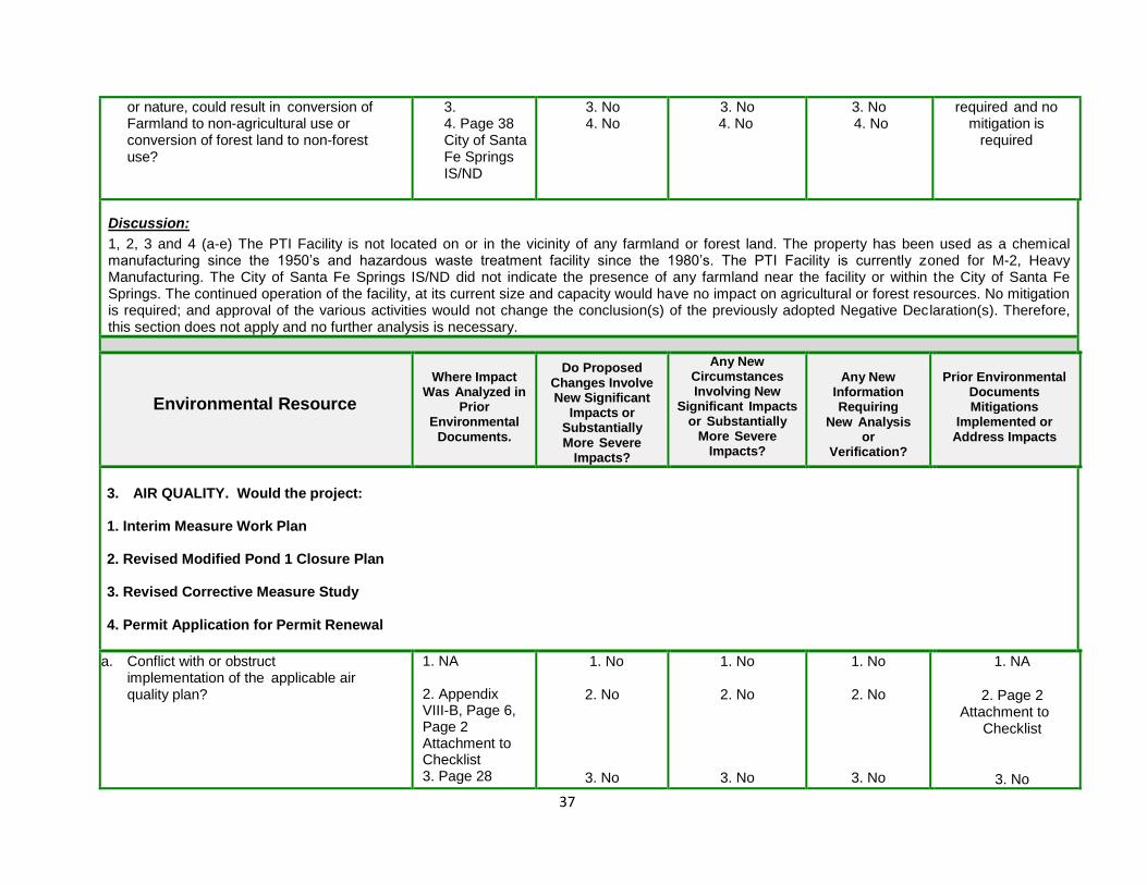
37
or nature, could result in conversion of Farmland to non-agricultural use or conversion of forest land to non-forest use?
3. 4. Page 38 City of Santa Fe Springs IS/ND
3. No 4. No
3. No 4. No
3. No 4. No
required and no mitigation is
required
Discussion:
1, 2, 3 and 4 (a-e) The PTI Facility is not located on or in the vicinity of any farmland or forest land. The property has been used as a chemical manufacturing since the 1950’s and hazardous waste treatment facility since the 1980’s. The PTI Facility is currently zoned for M-2, Heavy Manufacturing. The City of Santa Fe Springs IS/ND did not indicate the presence of any farmland near the facility or within the City of Santa Fe Springs. The continued operation of the facility, at its current size and capacity would have no impact on agricultural or forest resources. No mitigation is required; and approval of the various activities would not change the conclusion(s) of the previously adopted Negative Declaration(s). Therefore, this section does not apply and no further analysis is necessary.
Environmental Resource
Where Impact Was Analyzed in
Prior Environmental
Documents.
Do Proposed Changes Involve New Significant
Impacts or Substantially More Severe
Impacts?
Any New Circumstances Involving New
Significant Impacts or Substantially
More Severe Impacts?
Any New Information Requiring
New Analysis or
Verification?
Prior Environmental
Documents Mitigations
Implemented or Address Impacts
3. AIR QUALITY. Would the project: 1. Interim Measure Work Plan 2. Revised Modified Pond 1 Closure Plan 3. Revised Corrective Measure Study 4. Permit Application for Permit Renewal
a. Conflict with or obstruct implementation of the applicable air quality plan?
1. NA 2. Appendix VIII-B, Page 6, Page 2 Attachment to Checklist 3. Page 28
1. No
2. No
3. No
1. No
2. No
3. No
1. No
2. No
3. No
1. NA
2. Page 2 Attachment to
Checklist
3. No

38
Page 2 Initial Study Checklist 4. Appendix I Page 2 and City IS/ND Page 39
4. No
4. No
4.No
4. No
b. Violate any air quality standard or contribute substantially to an existing or projected air quality violation?
1. NA 2. Appendix VIII-B, Page 6, Page 2 Attachment to Checklist 3. Page 28 Page 2 Initial Study Checklist 4. Appendix I Page 2 and City IS/ND Page 39
1. No 2. No
3. No
4. No
1. No 2. No
3. No
4. No
1. No 2. No
3. No
4. No
1. NA 2. Page 2
Attachment to Checklist
3. No
4. No
c. Result in a cumulatively considerable net increase of any criteria pollutant for which the project region is non-attainment under an applicable federal or state ambient air quality standard (including releasing emissions which exceed quantitative thresholds for ozone precursors)?
1. NA 2. Appendix VIII-B, Page 6, Page 2 Attachment to Checklist 3. Page 28 Page 2 Initial Study Checklist 4. Appendix I Page 2 and City IS/ND Page 39
1. No 2. No
3. No
4. No
1. No 2. No
3. No
4. No
1. No 2. No
3. No
4. No
1. NA 2. Page 2
Attachment to Checklist
3. No
4. No
d. Expose sensitive receptors to substantial pollutant concentrations?
1. NA 2. Appendix VIII-B, Page 6, Page 2 Attachment to Checklist
1. No 2. No
1. No 2. No
1. No 2. No
1. NA 2. Page 2
Attachment to Checklist

39
3. Page 28 Page 2 Initial Study Checklist 4. Appendix I Page 2 and City IS/ND Page 39
3. No
4. No
3. No
4. No
3. No
4. No
3. No
4. No
e. Create objectionable odors affecting a substantial number of people?
1. NA 2. Appendix VIII-B, Page 6, Page 2 Attachment to Checklist 3. Page 28 Page 2 Initial Study Checklist 4. Appendix I Page 2 and City IS/ND Page 39
1. No 2. No
3. No
4. No
1. No 2. No
3. No
4. No
1. No 2. No
3. No
4. No
1. NA 2. Page 2
Attachment to Checklist
3. No
4. No
Discussion:
1(a-d). The Interim Measure Work Plan proposes the use of a truck-mounted, direct-push drill rig to advance small-diameter stainless steel injection rods into the subsurface to inject the CPS, which will treat soils contaminated with hexavalent chromium. The SCAQMD released a report in 2005 entitled Sample Construction Scenarios for Projects Less than Five Acres in Size, which contained emission factors for drill rigs. The amount of carbon monoxide (CO), nitric oxides (NOx), particulate matter up to 10 micrometers in size (PM10), Sulfur oxides (SOx), and volatile organic compounds (VOCs) emitted from a 120 Hp drill rig would be 0.471, 0.822, 0.072, 0.166, and 0.101 pounds/day respectively. The Work Plan states that the baseline sampling, CPS solution injection, and process monitoring will take approximately eight weeks. The drill rig would be in operation for approximately 7 days. Therefore, the total amount of the following criteria pollutants emitted from the operation would be approximately 3.3 lbs of CO, 5.8 lbs of NOx, 0.50 lbs of PM10, 1.2 lbs of SOx, and 0.71 lbs of VOC’s. A comparison of these emission levels with the SCAQMD Mass Daily Thresholds presented in the table below indicates that this element of the project would not violate any applicable air quality plan, exceed any air quality standard, result in a cumulatively considerable net increase of any criteria pollutant for which the project region is non-attainment, or expose sensitive receptors to substantial pollutant concentrations.
The Project site is located in the South Coast Air Basin (Air Basin) within the jurisdiction of the SCAQMD. The Air Basin is currently in non-attainment for the 1-hour ozone, 8-hour ozone, suspended particulate matter (PM10), particulate matter (PM2.5), and lead (Pb) standards. Air quality significance thresholds for daily emissions of criteria pollutants from construction and operation are the following:

40
SCAQMD Mass Daily Thresholds
Pollutant Construction (lbs/day) Operation (lbs/day)
NOx 100 55
VOC 75 55
PM10 150 150
PM2.5 55 55
SOx 150 150
CO 550 550
Lead 3 3
Source: http://www.aqmd.gov/docs/default-source/ceqa/handbook/scaqmd-air-quality-significance-thresholds.pdf?sfvrsn=2 accessed 9/2015
2 (a-d). The closure of Pond 1 will include the deconstruction and removal of Tanks W-1, W-2, W-3, and W-4, removal of the concrete basins, removal of a filter press under a variance, and excavation and removal of approximately 610 cubic yards of soil beneath the pond.
Tanks W-1, W-2, W-3, and W-4 will be cut into pieces that can be placed into a 30-cubic yard or 40-cubic yard roll-off bin staged near the Pond 1 containment basin. Sections removed may be handled by a small crane to prevent them from falling and for lifting into the roll-off bin. The tanks will be pressure washed before they are cut. If pressure washing proves ineffective, abrasive blasting methods will be used and preference shall be given to wet methods. All applicable provisions of SCAQMD Rule 1140 shall be followed to minimize the effects of carryover. Dry unconfined abrasive blasting shall not be used unless the abrasives have been approved for use by SCAQMD.
The use of the filter press associated with the wastewater treatment unit was authorized pursuant to a variance issued by the Toxics Branch of the DHS and the filter press will be closed pursuant to California Code of Regulations, title 22, division 4.5., Chapter 15. The plates will be removed from the filter press and managed as hazardous waste debris. The frames, surrounding areas on the structure, and structural support members under the filter presses will be washed with a high pressure water spray to remove accumulated sludge. Visqueen plastic will be draped around the equipment and used as necessary to confine the spray washing. A visual closure performance standard will be used. The cleaned metal components will be either be sent off site as scrap metal or sent to a landfill as non-hazardous waste. Piping will either be managed as a closure generated waste or cleaned to the closure performance standard and managed as non-hazardous waste.
The concrete basin of the former Pond 1 and containment area for Tanks W-3 and W-4 will be broken up with a diesel-powered backhoe/loader (such as a Caterpillar 416) with a demolition ram attachment or cut with a concrete saw. The backhoe/loader will be positioned outside the former Pond 1 area. A second diesel-powered wheeled front-end loader (such as a Caterpillar 950) will be stationed at grade and will be equipped with about a three cubic yard bucket and will be used to remove concrete floor sections created by the demolition ram or the concrete saw. The concrete pieces will be placed into roll-off bins or directly into dump trucks for offsite disposal.

41
A diesel-powered hydraulic excavator with extended arm with a two-three cubic yard bucket attachment will remove the soils and transfer them to another diesel powered wheeled front-end loader (such as a Caterpillar 950). The loader will place the soils directly into trucks or onto a remediation waste staging area to the west of Pond 1 near the rainwater tanks. The remediation waste staging area will be a poly liner (minimum 20 millimeter thickness) placed over the asphalt and concrete base. A perimeter berm will be placed beneath the base sheeting to prevent storm water run-on or run-off or fiber rolls shall be used to surround the base of the excavation spoils. Two separate areas may be constructed – one for soils that are suspected to be clean and another for soils suspected to be contaminated.
Alternatively, if the soil can be properly characterized based on the samples, it will be directly loaded into 20-cubic yard end-dump trucks.
During placement of soil onto the pile, mitigation measures shall be taken to reduce fugitive dust such as minimizing the drop height, or dampening the soil. Any soil storage piles and disturbed soil areas will be secured and covered at the end of the work day. If a storage pile or disturbed soil area remains inactive for longer than 10 days, additional precautions will be used to secure the cover, or the surfaces will be treated with appropriate dust suppressant compounds.
Once the soil is properly profiled, it will be loaded into 20-cubic yard end-dump trucks. While loading from the soil pile to the trucks, fugitive dust shall be minimized by using one or more of the following measures: minimizing the drop height into the end dump; dampening the soil; or using wind screens. Before leaving the site, trucks shall also be covered with a tight fitting tarp. It is estimated that up to 30 trucks will be used. If this soil loading takes place over two or three days, that will be 10 to 15 trucks per day. This is a minor increase in traffic levels compared with the 33,703 vehicles per day traveling on the primary route of Slauson Avenue near Dice Road, or the 12,774 vehicles per day at Los Nietos Road near Dice Road. Traffic at Los Nietos Road near Dice Road includes over 20 trucks per day.
For the purposes of this Closure Plan, it is expected that closure activities would generate the following waste shipments:
Truck shipment (bulk) of wastewater off-site from Tanks W-1 and W-2 –would generate between 12 and 15 tanker trucks
Rinse water from closure decontamination would require up to 10 tanker truck trips (if rinse water is not processed in an on-site wastewater plant)
Trucks or roll-off bins (20 cubic yard capacity) of closure-generated waste would require three to four trucks of concrete debris, one truck of miscellaneous solid debris, and about 30 – 33 trucks (20-cubic yard end-dumps) of excavated soil.
All diesel-fueled engines used in the closure work with a rating of 50 horsepower (hp) or higher and lower than 750 hp shall meet, at a minimum, the Tier 3 California Emission Standards for Off-Road Compression-Ignition Engines, as specified in California Code of Regulations, Title 13, section 2423(b)(1), unless such an engine is not available for that particular type of equipment. Engines larger than 750 hp shall meet Tier 2 engine standards. In the event that a Tier 3 engine is not available for any off-road equipment larger than 50 hp and smaller than 750 hp, that equipment shall be equipped with a Tier 2 engine, or an engine that is equipped with retrofit controls to reduce exhaust emissions of NOx and diesel particulate matter (DPM) to no more than Tier 2 levels unless certified by engine manufacturers that the use of such devices is not practical for that specific engine type. For purposes of this condition, the use of such devices is “not practical” for the following, as well as other, reasons:
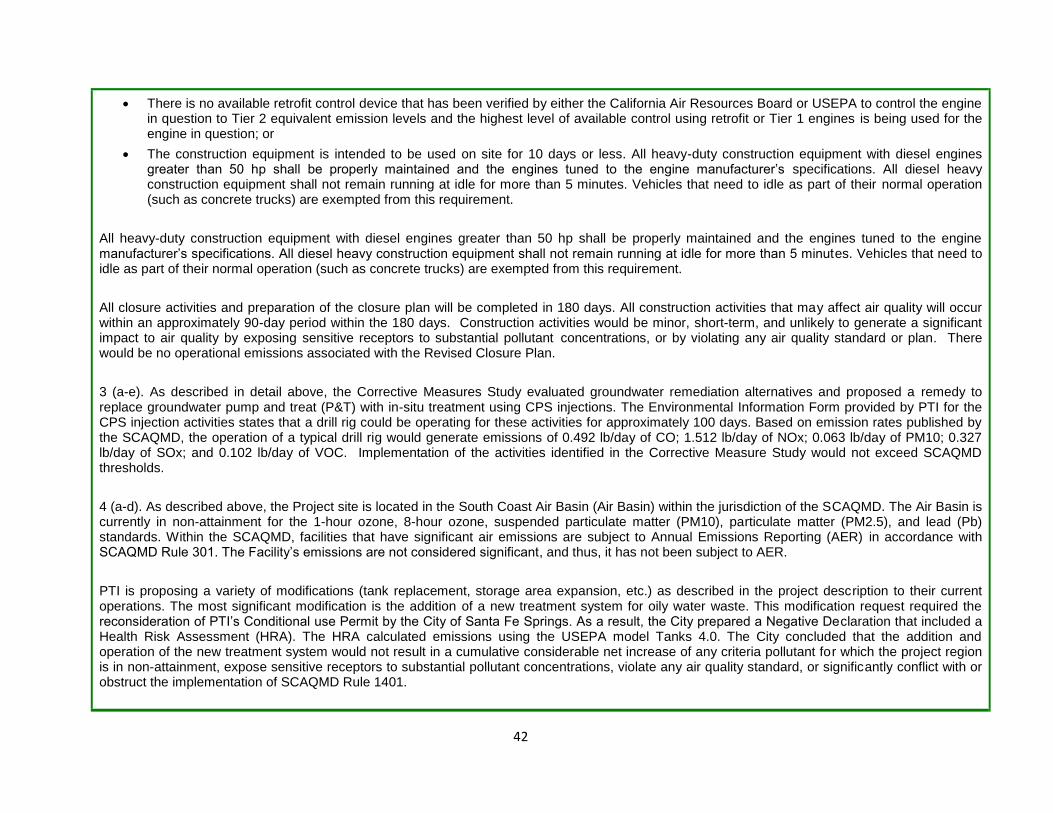
42
There is no available retrofit control device that has been verified by either the California Air Resources Board or USEPA to control the engine in question to Tier 2 equivalent emission levels and the highest level of available control using retrofit or Tier 1 engines is being used for the engine in question; or
The construction equipment is intended to be used on site for 10 days or less. All heavy-duty construction equipment with diesel engines greater than 50 hp shall be properly maintained and the engines tuned to the engine manufacturer’s specifications. All diesel heavy construction equipment shall not remain running at idle for more than 5 minutes. Vehicles that need to idle as part of their normal operation (such as concrete trucks) are exempted from this requirement.
All heavy-duty construction equipment with diesel engines greater than 50 hp shall be properly maintained and the engines tuned to the engine manufacturer’s specifications. All diesel heavy construction equipment shall not remain running at idle for more than 5 minutes. Vehicles that need to idle as part of their normal operation (such as concrete trucks) are exempted from this requirement.
All closure activities and preparation of the closure plan will be completed in 180 days. All construction activities that may affect air quality will occur within an approximately 90-day period within the 180 days. Construction activities would be minor, short-term, and unlikely to generate a significant impact to air quality by exposing sensitive receptors to substantial pollutant concentrations, or by violating any air quality standard or plan. There would be no operational emissions associated with the Revised Closure Plan.
3 (a-e). As described in detail above, the Corrective Measures Study evaluated groundwater remediation alternatives and proposed a remedy to replace groundwater pump and treat (P&T) with in-situ treatment using CPS injections. The Environmental Information Form provided by PTI for the CPS injection activities states that a drill rig could be operating for these activities for approximately 100 days. Based on emission rates published by the SCAQMD, the operation of a typical drill rig would generate emissions of 0.492 lb/day of CO; 1.512 lb/day of NOx; 0.063 lb/day of PM10; 0.327 lb/day of SOx; and 0.102 lb/day of VOC. Implementation of the activities identified in the Corrective Measure Study would not exceed SCAQMD thresholds.
4 (a-d). As described above, the Project site is located in the South Coast Air Basin (Air Basin) within the jurisdiction of the SCAQMD. The Air Basin is currently in non-attainment for the 1-hour ozone, 8-hour ozone, suspended particulate matter (PM10), particulate matter (PM2.5), and lead (Pb) standards. Within the SCAQMD, facilities that have significant air emissions are subject to Annual Emissions Reporting (AER) in accordance with SCAQMD Rule 301. The Facility’s emissions are not considered significant, and thus, it has not been subject to AER.
PTI is proposing a variety of modifications (tank replacement, storage area expansion, etc.) as described in the project description to their current operations. The most significant modification is the addition of a new treatment system for oily water waste. This modification request required the reconsideration of PTI’s Conditional use Permit by the City of Santa Fe Springs. As a result, the City prepared a Negative Declaration that included a Health Risk Assessment (HRA). The HRA calculated emissions using the USEPA model Tanks 4.0. The City concluded that the addition and operation of the new treatment system would not result in a cumulative considerable net increase of any criteria pollutant for which the project region is in non-attainment, expose sensitive receptors to substantial pollutant concentrations, violate any air quality standard, or significantly conflict with or obstruct the implementation of SCAQMD Rule 1401.

43
PTI operates ammonia and hydrochloric acid scrubbers that are connected to various tanks and process vessels within the Facility. These scrubbers abate emissions from onsite process and storage tanks. The scrubbers are regulated and permitted by the SCAQMD and are inspected and maintained regularly as required by their respective SCAQMD permit requirements.
Current Operations Health Risk Assessment (COHRA)
The COHRA, completed by PTI in January 2015 identified, evaluated, and characterized potential chronic hazards/risks to current and reasonably expected future on and offsite receptors posed by Site-related chemicals associated with the current Site operations. The COHRA did not assess whether the levels of chemicals detected in subsurface soil, soil gas, and groundwater pose an unacceptable risk to human health. The human health risk from historical releases was evaluated in a separate assessment.
The COHRA generally followed the procedures and methodologies originally presented in the COHRA Work Plan Addendum as amended and included: 1) development of emission rates for chemicals of potential concern; 2) transport and exposure assessment; 3) toxicity assessment; and 4) risk characterization. The COHRA was completed in conjunction with Yorke Engineering, LLC (Yorke), who modeled potential off-site and on-site health risks associated with diesel-fueled trucks at the Facility, and modeled the transport of fugitive emissions using source parameters provided by Iris Environmental.
The California Air Resources Board (CARB) maintains a list of Toxic Air Contaminants (TACs) for use in emissions evaluations. Of the chemicals used or processed at the facility during current operations, only nickel and hexavalent chromium are listed as TACs. Diesel Particulate Matter (DPM) is also a TAC and generated during operation of the PhibroTech facility. Nickel was not carried forward since when processed, it remains in a moist cake and thus it is not a potential particulate emission source. Hexavalent chromium was not carried forward since it represents less than one percent of chemicals processed at the facility, and is only received sporadically. The health risks from previous releases of hexavalent chromium to soil and groundwater were evaluated in a separate assessment
18.
The remaining chemicals identified as chemicals of potential concern (COPCs) for risk screening included:
Aqueous ammonia
Hydrochloric acid
Sulfuric acid
Nitric acid
Ferric oxide (dry)
Copper carbonate (dry)
Copper oxide (dry)
18
PTI submitted a Final Human Health Risk Assessment for Historical Releases to Soil and Groundwater to DTSC in February of 2015. The HHRA assessed whether the levels of chemicals detected in subsurface soil, soil gas, and groundwater at the Site could pose an unacceptable risk to human health. The assessment concluded that none of the chemicals posed a significant health risk to current offsite residential populations, or current and future onsite commercial workers.

44
The SCAQMD thresholds for TAC’s are the following:
Maximum Incremental Cancer Risk ≥ 10 in 1 million
Cancer Burden > 0.5 excess cancer cases (in areas ≥ 1 in 1 million)
Chronic & Acute Hazard Index ≥ 1.0 (project increment)
The results of the COHRA indicated that none of the chemical emissions modeled for the facility pose a significant health risk to current populations working at or nearby the Site or to current residential populations living near the facility. A summary of these results can be found in Section 7, page 25 of the COHRA.
Overall, no new circumstances or project changes have occurred nor has any substantial information been found that warrant preparation of a supplemental or subsequent environmental document. Therefore, the conclusions of the Negative Declarations remain valid and the proposed project activities would not result in new or substantially more severe significant impact to air quality.
1, 2, 3, 4 (e) Odors
During the subsurface injection of calcium polysulfide solution, evolved hydrogen sulfide gas may be formed on site. As a result, air monitoring will be conducted during excavation activities. Monitoring for hydrogen sulfide was performed during the CPS injections for the 2012 pilot test. During the pilot test, over 20,000 gallons of CPS solution were delivered to the site and subsequently diluted with water and injected into the soil. No detections of hydrogen sulfide were observed on the field instruments throughout the multi-week pilot test.
The PTI Facility has both ammonia (NH3) and hydrogen chloride (HCL) sensors located within the facility boundary and at the fence line. The HCL sensors are set up to report detections of airborne concentrations at 2.5 ppm. The NH3 sensors along the fence line are set up to report detections of airborne concentrations at 15 ppm. Sensors are inspected weekly.
On February 23, 2012, DTSC staff sampled the air in the neighborhood adjacent to PTI. Ammonia and VOCs were sampled from approx. 10 am to 12 pm. Dice Rd, Burke Rd, Skabo Rd, Walnut Rd, Verback Rd, Rivera Rd, Sorensen Td, and Altamar Street were surveyed. Ammonia was not detected above the detection limit of 1 ppm and VOC’s were not detected above the detection limit of 0.1 ppm.
DTSC has a hotline to call for nearby residents to report odors that they think may be coming from the PTI facility. Two complaints of foul odors from residents were received in May of 2012. Four complaints were received in June 2012. In response to these complaints, DTSC reviewed data of ammonia concentrations taken from fence line sensors at the facility and found that there were no detections above the detection limit. PTI is also required to comply with SCAQMD Rule 402, which states the following:
“A person shall not discharge from any source whatsoever such quantities of air contaminants or other material which cause in jury, detriment, nuisance, or annoyance to any considerable number of persons or to the public, or which endanger the comfort, repose, health or safety of any such persons or the public, or which cause, or have a natural tendency to cause, injury or damage to business or property.”

45
In addition, PTI works in coordination with SCAQMD, City of Santa Fe Springs Fire Department, and DTSC to resolve odor issues if any. No project changes have occurred that require preparation of a subsequent or supplemental environmental document. Air quality and emissions were reviewed and it was determined that the proposed activities would not generate air emissions in excess of current standards. Therefore, the conclusions of the previously adopted Negative Declarations remain valid and the proposed activities would not result in new or substantially more severe significant impacts to air quality.
References
South Coast Air Quality Manage District. SCAQMD Air Quality Significance Thresholds
http://www.aqmd.gov/docs/default-source/ceqa/handbook/scaqmd-air-quality-significance-thresholds.pdf?sfvrsn=2. Revised March 2015. Accessed September 2015.
South Coast Air Quality Manage District. Sample Construction Scenarios for Projects Less than Five Acres in Size.
http://www.aqmd.gov/docs/default-source/ceqa/handbook/localized-significance-thresholds/final-sample-construction-scenario-report.pdf?sfvrsn=2
February 2005. Accessed September 2015.
AECOM. Pond 1 Closure Plan. Phibro-Tech, Santa Fe Springs, California. May 2013, and revised June 2015, August 7, 2015, and September 2015.
DUDEK. Environmental Information Form. Phibro-Tech, Santa Fe Springs, California. May 29, 2015
Iris Environmental and York Engineering. Current Operations Health Risk Assessment. Phibro-Tech, Santa Fe Springs, California. January 15, 2015.
York Engineering. Part B Permit Application. Phibro-Tech, Santa Fe Springs, California. August 28, 2014.
Environmental Resource
Where Impact Was Analyzed in
Prior Environmental
Documents.
Do Proposed Changes Involve New Significant
Impacts or Substantially More Severe
Impacts?
Any New Circumstances Involving New
Significant Impacts or Substantially
More Severe Impacts?
Any New Information Requiring
New Analysis or
Verification?
Prior Environmental
Documents Mitigations
Implemented or Address Impacts
4. BIOLOGICAL RESOURCES. Would the project: 1. Interim Measure Work Plan 2. Revised Modified Pond 1 Closure Plan 3. Revised Corrective Measure Study 4. Permit Application for Permit Renewal
a. Have a substantial adverse effect, either directly or through habitat modifications,
1. NA 2. Page 8
1. No 2. No
1. No 2. No
1. No 2. No
No prior mitigation

46
on any species identified as a candidate, sensitive, or special status species in local or regional plans, policies, or regulations, or by the California Department of Fish and Game or U.S. Fish and Wildlife Service?
Appendix VIII-B 3. Page 5 and 6
Initial Study Checklist 4. Page 3 Initial
Study Checklist, Page 48 City IS/ND
3. No
4. No
3. No
4. No
3. No
4. No
measures were required and no
mitigation is required
b. Have a substantial adverse effect on any riparian habitat or other sensitive natural community identified in local or regional plans, policies, or regulations or by the California Department of Fish and Game or US Fish and Wildlife Service?
1. No 2. No 3. No 4. No
1. No 2. No 3. No 4. No
1. No 2. No 3. No 4. No
No prior mitigation measures were required and no
mitigation is required
c. Have a substantial adverse effect on federally protected wetlands as defined by Section 404 of the Clean Water Act (including, but not limited to, marsh, vernal pool, coastal, etc.) through direct removal, filling, hydrological interruption, or other means?
1. No 2. No 3. No 4. No
1. No 2. No 3. No 4. No
1. No 2. No 3. No 4. No
No prior mitigation measures were required and no
mitigation is required
d. Interfere substantially with the movement of any native resident or migratory fish and wildlife species or with established native resident or migratory wildlife corridors, or impede the use of native wildlife nursery sites?
1. No 2. No 3. No 4. No
1. No 2. No 3. No 4. No
1. No 2. No 3. No 4. No
No prior mitigation measures were required and no
mitigation is required
e. Conflict with any local policies or ordinances protecting biological resources, such as a tree preservation policy or ordinance?
1. No 2. No 3. No 4. No
1. No 2. No 3. No 4. No
1. No 2. No 3. No 4. No
No prior mitigation measures were required and no
mitigation is required
f. Conflict with the provisions of an adopted Habitat Conservation Plan, Natural
1. No 2. No
1. No 2. No
1. No 2. No
No prior mitigation measures were
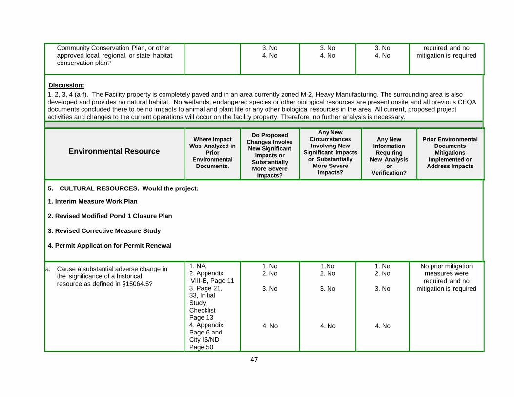
47
Community Conservation Plan, or other approved local, regional, or state habitat conservation plan?
3. No 4. No
3. No 4. No
3. No 4. No
required and no mitigation is required
Discussion:
1, 2, 3, 4 (a-f). The Facility property is completely paved and in an area currently zoned M-2, Heavy Manufacturing. The surrounding area is also developed and provides no natural habitat. No wetlands, endangered species or other biological resources are present onsite and all previous CEQA documents concluded there to be no impacts to animal and plant life or any other biological resources in the area. All current, proposed project activities and changes to the current operations will occur on the facility property. Therefore, no further analysis is necessary.
Environmental Resource
Where Impact Was Analyzed in
Prior Environmental
Documents.
Do Proposed Changes Involve New Significant
Impacts or Substantially More Severe
Impacts?
Any New Circumstances Involving New
Significant Impacts or Substantially
More Severe Impacts?
Any New Information Requiring
New Analysis or
Verification?
Prior Environmental
Documents Mitigations
Implemented or Address Impacts
5. CULTURAL RESOURCES. Would the project: 1. Interim Measure Work Plan 2. Revised Modified Pond 1 Closure Plan 3. Revised Corrective Measure Study 4. Permit Application for Permit Renewal
a. Cause a substantial adverse change in the significance of a historical resource as defined in §15064.5?
1. NA 2. Appendix VIII-B, Page 11 3. Page 21, 33, Initial Study Checklist Page 13 4. Appendix I Page 6 and City IS/ND Page 50
1. No 2. No
3. No
4. No
1.No 2. No
3. No
4. No
1. No 2. No
3. No
4. No
No prior mitigation measures were required and no
mitigation is required
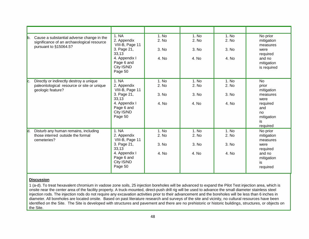
48
b. Cause a substantial adverse change in the significance of an archaeological resource pursuant to §15064.5?
1. NA 2. Appendix VIII-B, Page 11 3. Page 21, 33,13 4. Appendix I Page 6 and City IS/ND Page 50
1. No 2. No
3. No
4. No
1. No 2. No
3. No
4. No
1. No 2. No
3. No
4. No
No prior mitigation measures were required and no mitigation is required
c. Directly or indirectly destroy a unique paleontological resource or site or unique geologic feature?
1. NA 2. Appendix VIII-B, Page 11 3. Page 21, 33,13 4. Appendix I Page 6 and City IS/ND Page 50
1. No 2. No
3. No
4. No
1. No 2. No
3. No
4. No
1. No 2. No
3. No
4. No
No prior mitigation measures were required and no mitigation is required
d. Disturb any human remains, including those interred outside the formal cemeteries?
1. NA 2. Appendix VIII-B, Page 11 3. Page 21, 33,13 4. Appendix I Page 6 and City IS/ND Page 50
1. No 2. No
3. No
4. No
1. No 2. No
3. No
4. No
1. No 2. No
3. No
4. No
No prior mitigation measures were required and no mitigation is required
Discussion
1 (a-d). To treat hexavalent chromium in vadose zone soils, 25 injection boreholes will be advanced to expand the Pilot Test injection area, which is onsite near the center area of the facility property. A truck-mounted, direct-push drill rig will be used to advance the small diameter stainless steel injection rods. The injection rods do not require any excavation activities prior to their advancement and the boreholes will be less than 6 inches in diameter. All boreholes are located onsite. Based on past literature research and surveys of the site and vicinity, no cultural resources have been identified on the Site. The Site is developed with structures and pavement and there are no prehistoric or historic buildings, structures, or objects on the Site.

49
2. 3. 4 (a-d). Under the California Code of Regulations Title 14 section 15064.5(a) is a list of items that are considered to be “historical resources”. Previous CEQA documents have not indicated the presence of any of these items onsite. Previous public comments to DTSC have indicated that the PTI site was used by a foundry in the 1920’s. PTI, in their Environmental Information Form submitted to DTSC on May 29, 2015, stated that a foundry operated at the site from the late 1940’s to the early 1950’s. The foundry and all remnants were removed when the current facility was constructed.
The current project site is fully paved and developed, with the exception of some minor, perimeter landscaping. All previous CEQA documents indicated no impacts to Cultural Resources. The modifications to the facilities operations as described in the current permit application (Part B) will require several excavation of previously disturbed material at various locations on the property. The depth of the excavations range from 3 feet to a maximum of 10 feet below ground surface. If any archaeological or paleontological items are encountered, steps to analyze and protect those items must be conducted in accordance with CEQA guidelines section 15064.5. Therefore, it is anticipated that there will be no impact to any historical resources from the proposed project activities and no further analysis is necessary.
Environmental Resource
Where Impact Was Analyzed in
Prior Environmental
Documents.
Do Proposed Changes Involve New Significant
Impacts or Substantially More Severe
Impacts?
Any New Circumstances Involving New
Significant Impacts or Substantially
More Severe Impacts?
Any New Information Requiring
New Analysis or
Verification?
Prior Environmental
Documents Mitigations
Implemented or Address Impacts
6. GEOLOGY AND SOILS. Would the project: 1. Interim Measure Work Plan 2. Revised Modified Pond 1 Closure Plan 3. Revised Corrective Measure Study 4. Permit Application for Permit Renewal
a. Expose people or structures to potential substantial adverse effects, including the risk of loss, injury, or death involving: i. Rupture of a known earthquake fault,
as delineated on the most recent Alquist-Priolo Earthquake Fault Zoning Map issued by the State Geologist for the area or based on
1. NA 2. Page 6
and 7 Appendix
VIII-B 3. Pages 5-7, 10, page
1 of
1. No 2. No
3. No
1. No 2. No
3. No
1. No 2. No
3. No
No prior mitigation measures were required and no
mitigation is required

50
other substantial evidence of a known fault? Refer to Division of Mines and
Geology Special Publication 42.
ii. Strong seismic ground shaking? iii. Seismic-related ground failure,
including liquefaction? iv. Landslides?
checklist 4. Page 1
Appendix I, Page 51-53 City IS/ND
4. No
4. No
4. No
b. Result in substantial soil erosion or the loss of topsoil?
1. NA 2. Page 6
and 7 Appendix
VIII-B 3. Pages 5-7, 10, page
1 of checklist
4. Page 1 Appendix I, Page 51-53 City IS/ND
1. No 2. No
3. No
4. No
1. No 2. No
3. No
4. No
1. No 2. No
3. No
4. No
No prior mitigation measures were required and no
mitigation is required
c. Be located on a geologic unit or soil that is unstable, or that would become unstable as a result of the project, and potentially result in on-or off-site landslide, lateral spreading, subsidence, liquefaction or collapse?
1. NA 2. Page 6
and 7 Appendix
VIII-B 3. Pages 5-7, 10, page
1 of checklist 4. Page 1
Appendix I, Page 51-53 City IS/ND
1. No 2. No
3. No
4. No
1. No 2. No
3. No
4. No
1. No 2. No
3. No
4. No
No prior mitigation measures were required and no
mitigation is required
d. Be located on expansive soil, as defined in Table 18- 1-B of the Uniform Building Code (1994), creating substantial risks to life or property?
1. NA 2. Page 6
and 7 Appendix
VIII-B 3. Pages 5-7, 10, page
1 of
1. No 2. No
3. No
1. No 2. No
3. No
1. No 2. No
3. No
No prior mitigation measures were required and no
mitigation is required

51
checklist 4. Page 1
Appendix I, Page 51-53 City IS/ND
4. No
4. No
4. No
e. Have soils incapable of adequately supporting the u s e of septic tanks or alternative wastewater disposal systems where sewers are not available for the disposal of wastewater?
1. NA 2. Page 6
and 7 Appendix
VIII-B 3. Pages 5-7, 10, page
1 of checklist 4. Page 1
Appendix I, Page 51-53 City IS/ND
1. No 2. No
3. No
4. No
1. No 2. No
3. No
4. No
1. No 2. No
3. No
4. No
No prior mitigation measures were required and no
mitigation is required
Discussion: 1, 2, 3, 4. a) The California Department of Conservation has not published an Alquist-Priolo Earthquake Fault Zoning Map for the City, likely because no known surface faults, active or otherwise, are located in the City or on the Project site. However, the Puente Hills Blind Thrust (PBT) fault is located beneath the City. A blind thrust fault does not rupture all the way up to the surface, resulting in a lack of evidence of it at the ground surface. The Santa Fe Springs segment of the PBT is beneath the Santa Fe Springs anticline (fold). This fold provides structural trap for the Santa Fe Springs oil field. The PHT is thought to be responsible for the 1987 Whittier Narrows Earthquake. b) All soil excavated due to remediation or tank system replacement will be backfilled. Therefore, there will be no substantial loss of topsoil. c) The Department of Conservation’s Seismic Hazard Zone Map: Whittier Quadrangle shows the Project site being located outside of an area susceptible to liquefaction, landslide, or other seismically induced, geological condition. d) The surficial and near surface soils across the site have been sampled and characterized by a California Licensed Professional Engineering Geologist. These soils contain substantial percentages of fine gravels, sand, and silt, in addition to low percentages of clays. Laboratory and field tests have demonstrated that the clay fraction in the soil is not of an expansive mineralogy. Therefore the soils at the site are not expansive as defined in Table 18-1-B of the Uniform Building Code (1994). e) The Facility currently connects to the municipal sanitary sewer system and no septic or alternative wastewater disposal systems are proposed as part of the Projects. Based on the above information, it is anticipated there will be no significant impacts from implementation of the projects currently under consideration No new circumstances or project changes have occurred nor has any substantially important new information been found requiring new analysis or verification. Therefore, the conclusions of the prior Negative Declaration(s) remain valid and the proposed activities would not result in new or substantially more severe significant impacts to geology, soils, or seismicity.

52
References: Department of Agriculture, U.S. 2013. Web Soil Survey; Department of Conservation, California. 2007. Regional Geologic Hazards and Mapping Program: Regulatory Map Search; Department of Conservation. California. 1999. Seismic Hazard Zone Map: Whittier Quadrangle; Iris Environmental. 2015. Final Human Health Risk Assessment for Historical Releases to Soil and Groundwater.
Environmental Resource
Where Impact Was Analyzed in
Prior Environmental
Documents.
Do Proposed Changes Involve New Significant
Impacts or Substantially More Severe
Impacts?
Any New Circumstances Involving New
Significant Impacts or Substantially
More Severe Impacts?
Any New Information Requiring
New Analysis or
Verification?
Prior Environmental
Documents Mitigations
Implemented or Address Impacts
7. GREENHOUSE GAS EMISSIONS. Would the project: 1. Interim Measure Work Plan 2. Revised Modified Pond 1 Closure Plan 3. Revised Corrective Measure Study 4. Permit Application for Permit Renewal
a. Generate greenhouse gas emissions, either directly or indirectly, that may have a significant impact on the environment?
1. NA 2. NA 3. NA 4. NA,
City IS/ND Pages 42-45
1. No 2. No 3. No 4. No
1. No 2. No 3. No 4. No
1. No 2. No 3. No 4. No
No mitigation is required
b. Conflict with an applicable plan, policy or regulation adopted for the purpose of reducing the emission of greenhouse gases?
1. NA 2. NA 3. NA 4. NA,
City IS/ND Pages 42-45
1. No 2. No 3. No 4. No
1. No 2. No 3. No 4. No
1. No 2. No 3. No 4. No
No mitigation is required
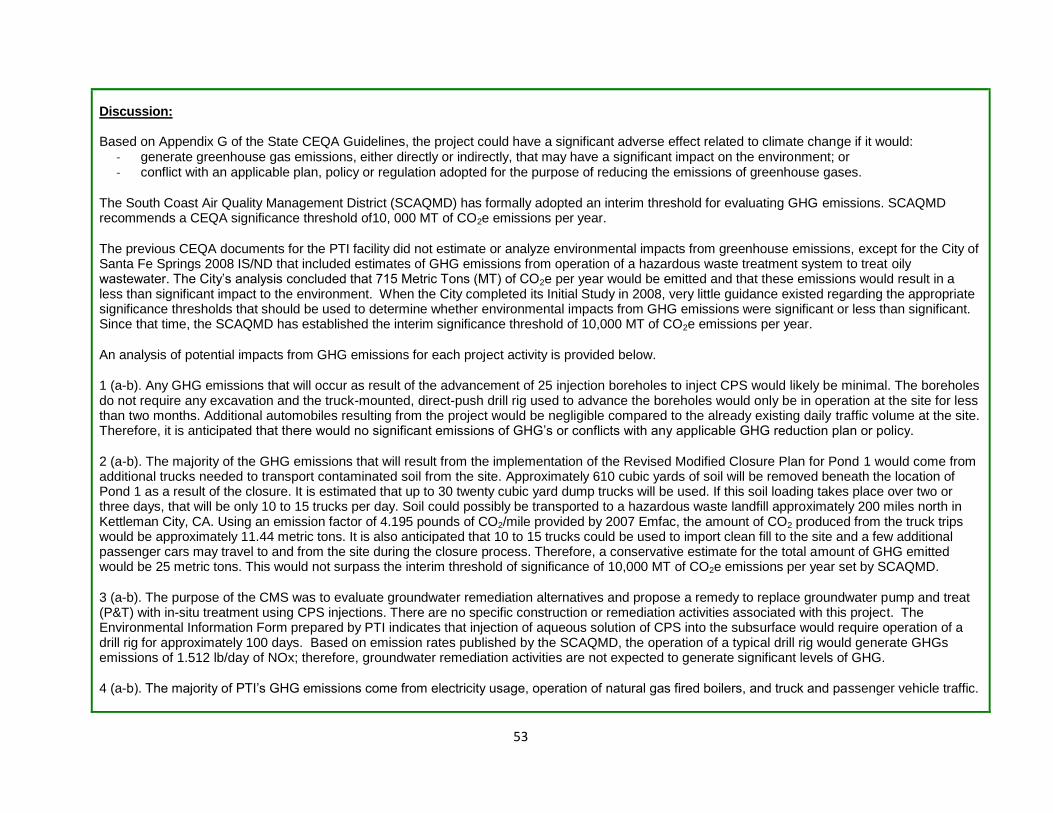
53
Discussion: Based on Appendix G of the State CEQA Guidelines, the project could have a significant adverse effect related to climate change if it would: - generate greenhouse gas emissions, either directly or indirectly, that may have a significant impact on the environment; or - conflict with an applicable plan, policy or regulation adopted for the purpose of reducing the emissions of greenhouse gases.
The South Coast Air Quality Management District (SCAQMD) has formally adopted an interim threshold for evaluating GHG emissions. SCAQMD recommends a CEQA significance threshold of10, 000 MT of CO2e emissions per year. The previous CEQA documents for the PTI facility did not estimate or analyze environmental impacts from greenhouse emissions, except for the City of Santa Fe Springs 2008 IS/ND that included estimates of GHG emissions from operation of a hazardous waste treatment system to treat oily wastewater. The City’s analysis concluded that 715 Metric Tons (MT) of CO2e per year would be emitted and that these emissions would result in a less than significant impact to the environment. When the City completed its Initial Study in 2008, very little guidance existed regarding the appropriate significance thresholds that should be used to determine whether environmental impacts from GHG emissions were significant or less than significant. Since that time, the SCAQMD has established the interim significance threshold of 10,000 MT of CO2e emissions per year. An analysis of potential impacts from GHG emissions for each project activity is provided below. 1 (a-b). Any GHG emissions that will occur as result of the advancement of 25 injection boreholes to inject CPS would likely be minimal. The boreholes do not require any excavation and the truck-mounted, direct-push drill rig used to advance the boreholes would only be in operation at the site for less than two months. Additional automobiles resulting from the project would be negligible compared to the already existing daily traffic volume at the site. Therefore, it is anticipated that there would no significant emissions of GHG’s or conflicts with any applicable GHG reduction plan or policy. 2 (a-b). The majority of the GHG emissions that will result from the implementation of the Revised Modified Closure Plan for Pond 1 would come from additional trucks needed to transport contaminated soil from the site. Approximately 610 cubic yards of soil will be removed beneath the location of Pond 1 as a result of the closure. It is estimated that up to 30 twenty cubic yard dump trucks will be used. If this soil loading takes place over two or three days, that will be only 10 to 15 trucks per day. Soil could possibly be transported to a hazardous waste landfill approximately 200 miles north in Kettleman City, CA. Using an emission factor of 4.195 pounds of CO2/mile provided by 2007 Emfac, the amount of CO2 produced from the truck trips would be approximately 11.44 metric tons. It is also anticipated that 10 to 15 trucks could be used to import clean fill to the site and a few additional passenger cars may travel to and from the site during the closure process. Therefore, a conservative estimate for the total amount of GHG emitted would be 25 metric tons. This would not surpass the interim threshold of significance of 10,000 MT of CO2e emissions per year set by SCAQMD. 3 (a-b). The purpose of the CMS was to evaluate groundwater remediation alternatives and propose a remedy to replace groundwater pump and treat (P&T) with in-situ treatment using CPS injections. There are no specific construction or remediation activities associated with this project. The Environmental Information Form prepared by PTI indicates that injection of aqueous solution of CPS into the subsurface would require operation of a drill rig for approximately 100 days. Based on emission rates published by the SCAQMD, the operation of a typical drill rig would generate GHGs emissions of 1.512 lb/day of NOx; therefore, groundwater remediation activities are not expected to generate significant levels of GHG. 4 (a-b). The majority of PTI’s GHG emissions come from electricity usage, operation of natural gas fired boilers, and truck and passenger vehicle traffic.

54
The City of Santa Fe Springs’ IS/ND stated that PTI’s average electrical demand is 1,555 Megawatt-hours per year (MWh/yr) and that the oily waste expansion project would increase this consumption by 20%, bringing the total average to 1,866 MWh/yr. The IS/ND used a 2006 California Climate Action Registry (CCAR) composite emission factor of 641.26 pounds of GHGs (CO2e) per MWh for GHGs from PTI’s electrical utility, Southern California Edison. The City determined that approximately 90 MT of additional of CO2e would be emitted per year. Using this same emission factor (updated CCAR 2011 factor is less), it is estimated that the entire facility’s electricity demand will create, on average approximately 543 MT/year CO2e. In Section B of PTI’s draft Operations Plan for the proposed Hazardous Waste Facility Permit, average weekly traffic volumes are summarized for the site. Approximately, 310 passenger cars per week could travel to and from PTI as well as up to 190 trucks containing waste, raw material, or products. This equates to approximately 16,120 passenger cars and 9,880 trucks per year arriving to and departing from the facility. Using the estimated average round trip lengths from the City of Santa Fe Springs IS/ND for trucks (100 miles) and passenger cars (38.4 miles) and the emissions factors from 2007 EMFAC, CO2 emissions for the majority of the facility’s transportation activities can be calculated. The total amount of CO2 emitted from passenger cars and trucks carrying hazardous waste is approximately 2,196 MT/year. The following information regarding the two natural gas boilers was submitted to DTSC by PTI in their May 29, 2015 Environmental Information Form. One (1) Hurst boiler is operated on the Project site. This boiler operates at 10.5 million BTU per hour. This boiler is permitted by the SCAQMD to emit no more than 9 part per million (PPM) of NOx. In addition, an industrial boiler also is operated onsite. This boiler operates at 3.35 million BTU per hour. Unlike the permit issued for the Hurst boiler, the SCAQMD permit issued for the industrial boiler does not specify a maximum permitted NOx emissions output. In separate guidance published by the SCAQMD, the agency finds that industrial boilers emit the following controlled maximum daily outputs of GHGs: 7.0 lb/day of NOx. For the last year, heat duty to the Hurst boiler was 177,854 therms and 3,515 therms to the standby boiler. This amount of natural gas combustion results in 963 metric tons per year of CO2E emissions.
Sources GHG Emissions (MT/year CO2e)
Cars & Heavy-duty Trucks 2221
Natural Gas Boiler 963
Electrical Consumption 543
Total 3727 There are several other small excavations that will occur as a result of the replacement and construction of new tank systems and equipment, modified storage areas, etc. However, none of these excavations will be larger than the excavation proposed for the closure of Pond 1 and CO2 emitted from the trucks transporting soil from this closure is estimated to total 25 MT. The table above lists the sources that produce the majority of GHG emissions and the 3727 MT of CO2e per year produced from these sources is far less than the 10,000 MT significance threshold established by the SCAQMD. Therefore, there would not be any conflict with an applicable plan, policy or regulation adopted for the purpose of reducing the emission of greenhouse gases because there would a less than significant impact to the environment as a result of the GHG emissions emitted from the projects.
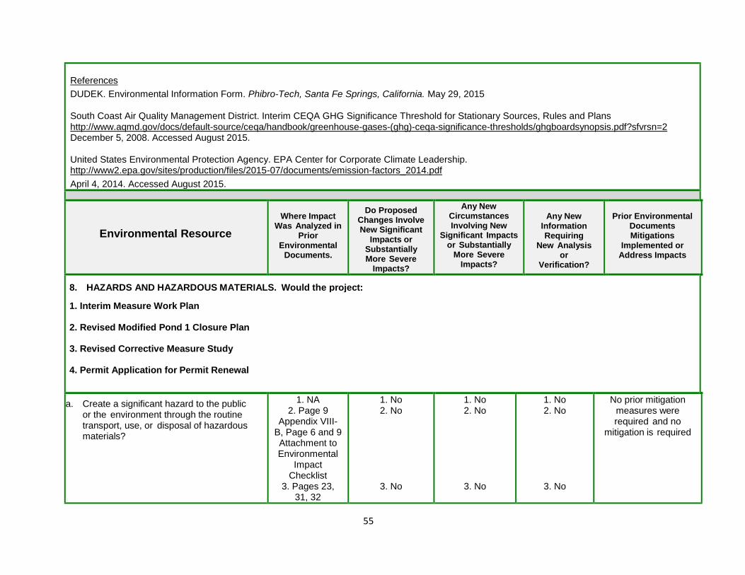
55
References
DUDEK. Environmental Information Form. Phibro-Tech, Santa Fe Springs, California. May 29, 2015
South Coast Air Quality Management District. Interim CEQA GHG Significance Threshold for Stationary Sources, Rules and Plans http://www.aqmd.gov/docs/default-source/ceqa/handbook/greenhouse-gases-(ghg)-ceqa-significance-thresholds/ghgboardsynopsis.pdf?sfvrsn=2 December 5, 2008. Accessed August 2015. United States Environmental Protection Agency. EPA Center for Corporate Climate Leadership. http://www2.epa.gov/sites/production/files/2015-07/documents/emission-factors_2014.pdf
April 4, 2014. Accessed August 2015.
Environmental Resource
Where Impact Was Analyzed in
Prior Environmental
Documents.
Do Proposed Changes Involve New Significant
Impacts or Substantially More Severe
Impacts?
Any New Circumstances Involving New
Significant Impacts or Substantially
More Severe Impacts?
Any New Information Requiring
New Analysis or
Verification?
Prior Environmental
Documents Mitigations
Implemented or Address Impacts
8. HAZARDS AND HAZARDOUS MATERIALS. Would the project: 1. Interim Measure Work Plan 2. Revised Modified Pond 1 Closure Plan 3. Revised Corrective Measure Study 4. Permit Application for Permit Renewal
a. Create a significant hazard to the public or the environment through the routine transport, use, or disposal of hazardous materials?
1. NA 2. Page 9
Appendix VIII-B, Page 6 and 9 Attachment to Environmental
Impact Checklist
3. Pages 23, 31, 32
1. No 2. No
3. No
1. No 2. No
3. No
1. No 2. No
3. No
No prior mitigation measures were required and no
mitigation is required

56
4. Page 4, 6 and footnote
#3, Page 54 of City’s IS/ND
4. No 4. No 4. No
b. Create a significant hazard to the public or the environment through reasonably foreseeable upset and accident conditions involving the release of hazardous materials into the environment?
1. NA 2. Page 6 and 9 Attachment to Environmental
Impact Checklist
3. Pages 23, 31, 32
4. Page 4, 6 and footnote
#3, Page 54 of City’s IS/ND
1. No 2. No
3. No
4. No
1. No 2. No
3. No
4. No
1. No 2. No
3. No
4. No
No prior mitigation measures were required and no
mitigation is required
c. Emit hazardous emissions or handle hazardous or acutely hazardous materials, substances, or waste within one-quarter mile of an existing or proposed school?
1. NA 2. 3.
4. Page 4, 6 and footnote
#3, Page 54 of City’s IS/ND
1. No 2. No 3. No 4. No
1. No 2. No 3. No 4. No
1. No 2. No 3. No 4. No
No prior mitigation measures were required and no
mitigation is required
d. Be located on a site which is included on a list of hazardous materials sites compiled pursuant to Government Code Section 65962.5 and, as a result, would it create a significant hazard to the public or the environment?
1. NA 2. Page 6 and 9 Attachment to Environmental
Impact Checklist
3. Pages 23, 31, 32
4. Page 4, 6 and footnote
#3,
Page 54 of City’s IS/ND
1. No 2. No
3. No
4. No
1. No 2. No
3. No
4. No
1. No 2. No
3. No
4. No
No prior mitigation measures were required and no
mitigation is required
e. For a project located within an airport land NA 1. NA 1. NA 1. NA No prior mitigation

57
use plan or, where such a plan has not been adopted, within two miles of a public airport or public use airport, would the project result in a safety hazard for people residing or working in the project area?
2. NA 3. NA 4. NA
2. NA 3. NA 4. NA
2. NA 3. NA 4. NA
measures were required and no
mitigation is required
f. For a project within the vicinity of a private airstrip, would the project result in a safety hazard for people residing or working on the project area?
NA
1. NA 2. NA 3. NA 4. NA
1. NA 2. NA 3. NA 4. NA
1. NA 2.NA 3.NA 4. NA
No prior mitigation measures were required and no
mitigation is required
g. Impair implementation of or physically interfere with an adopted emergency response plan or emergency evacuation plan?
1. No 2. No 3. No 4. No
1. No 2. No 3. No 4. No
1. No 2. No 3. No 4. No
No prior mitigation measures were required and no
mitigation is required
h. Expose people or structures to a significant risk of loss, injury or death involving wildland fires, including where wildlands are adjacent to urbanized areas or where residences are intermixed with wild lands?
NA 1. No 2. No 3. No 4. No
1. No 2. No 3. No 4. No
1. No 2. No 3. No 4. No
No prior mitigation measures were required and no
mitigation is required
Discussion:
1 (a-b). The Proposed Interim Measures Work Plan involves the in-situ treatment via injection of CPS to site soils contaminated with hexavalent chromium. The purpose of the injections is to reduce the chance of exposure to a hazardous waste, which in this case is hexavalent chromium. As described above in the project description, when handled in accordance with standard safety precautions, CPS is not a risk to public health or the environment. The Interim Measure Work Plan states that it is anticipated that the project can be completed using Level D personal protection. The project does not involve the routine transport, use, or disposal of hazardous materials, nor will it result in any hazardous emissions.
During the subsurface injection of calcium polysulfide solution, evolved hydrogen sulfide gas may be formed on site. As a result, air monitoring will be conducted during excavation activities. Monitoring for hydrogen sulfide was performed during the CPS injections for the 2012 pilot test. During the pilot test, over 20,000 gallons of CPS solution were delivered to the site and subsequently diluted with water and injected into the soil. No detections of hydrogen sulfide were observed on the field instruments throughout the multi-week pilot test.
Overall, the goal of the project is to improve the environment by completing in-situ treatment and reducing hexavalent chromium to the more thermodynamically stable trivalent chromium, which can precipitate or adsorb to soil. Because CPS is a non-toxic, benign material, implementation of the IM would not result in a short-term increase in risk. Therefore, there will be no impacts to the environment from hazardous materials.
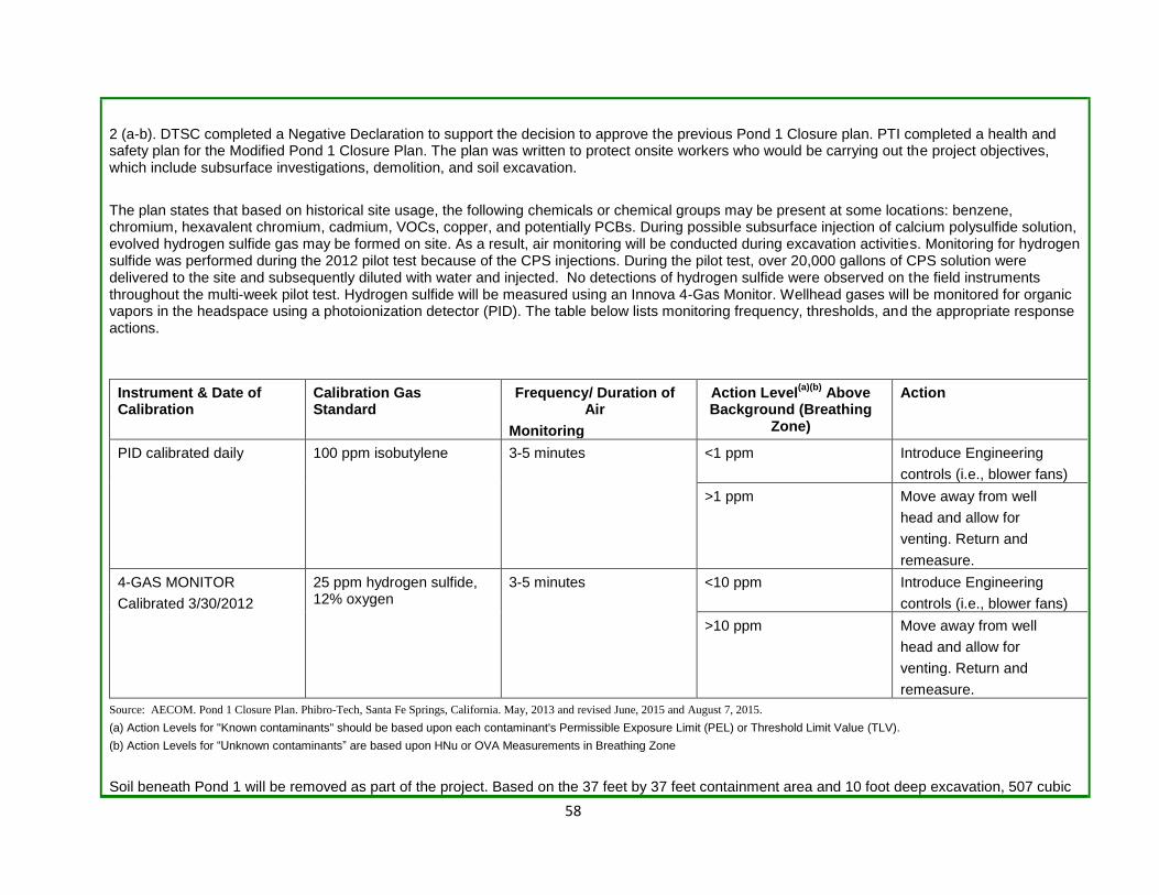
58
2 (a-b). DTSC completed a Negative Declaration to support the decision to approve the previous Pond 1 Closure plan. PTI completed a health and safety plan for the Modified Pond 1 Closure Plan. The plan was written to protect onsite workers who would be carrying out the project objectives, which include subsurface investigations, demolition, and soil excavation.
The plan states that based on historical site usage, the following chemicals or chemical groups may be present at some locations: benzene, chromium, hexavalent chromium, cadmium, VOCs, copper, and potentially PCBs. During possible subsurface injection of calcium polysulfide solution, evolved hydrogen sulfide gas may be formed on site. As a result, air monitoring will be conducted during excavation activities. Monitoring for hydrogen sulfide was performed during the 2012 pilot test because of the CPS injections. During the pilot test, over 20,000 gallons of CPS solution were delivered to the site and subsequently diluted with water and injected. No detections of hydrogen sulfide were observed on the field instruments throughout the multi-week pilot test. Hydrogen sulfide will be measured using an Innova 4-Gas Monitor. Wellhead gases will be monitored for organic vapors in the headspace using a photoionization detector (PID). The table below lists monitoring frequency, thresholds, and the appropriate response actions.
Instrument & Date of Calibration
Calibration Gas Standard
Frequency/ Duration of Air
Monitoring
Action Level(a)(b)
Above Background (Breathing
Zone)
Action
PID calibrated daily 100 ppm isobutylene 3-5 minutes <1 ppm Introduce Engineering
controls (i.e., blower fans)
>1 ppm Move away from well
head and allow for
venting. Return and
remeasure.
4-GAS MONITOR
Calibrated 3/30/2012
25 ppm hydrogen sulfide, 12% oxygen
3-5 minutes <10 ppm Introduce Engineering
controls (i.e., blower fans)
>10 ppm Move away from well
head and allow for
venting. Return and
remeasure.
Source: AECOM. Pond 1 Closure Plan. Phibro-Tech, Santa Fe Springs, California. May, 2013 and revised June, 2015 and August 7, 2015.
(a) Action Levels for "Known contaminants" should be based upon each contaminant's Permissible Exposure Limit (PEL) or Threshold Limit Value (TLV).
(b) Action Levels for “Unknown contaminants” are based upon HNu or OVA Measurements in Breathing Zone
Soil beneath Pond 1 will be removed as part of the project. Based on the 37 feet by 37 feet containment area and 10 foot deep excavation, 507 cubic
59
yards (in ground) will be excavated which is estimated to be about 610 cubic yards as excavated. During placement of soil onto the pile, mitigation measures shall be taken to reduce fugitive dust such as minimizing the drop height, or dampening the soil. Any soil storage piles and disturbed soil areas will be secured and covered at the end of the workday. If a storage pile or disturbed soil area remains inactive for longer than 10 days, additional precautions will be used to secure the cover, or the surfaces will be treated with appropriate dust suppressant compounds.
Once the soil is properly profiled, it will be loaded into 20-cubic yard end-dump trucks. While loading from the soil pile to the trucks, fugitive dust shall be minimized by using one or more of the following measures: minimizing the drop height into the end dump; dampening the soil; or using windscreens. Before leaving the site, trucks shall also be covered with a tight fitting tarp.
Activities associated with the closure are not expected to create a significant hazard to the public or the environment through the routine transport, use, or disposal of hazardous materials nor emit hazardous emissions or handle hazardous or acutely hazardous materials, substances. Transportation offsite of contaminated soil will not be routine once the closure is complete. Because of the controls in place during the removal of contaminated soil and subsurface injections, it is anticipated that there would be no significant impacts to the public resulting from exposure to hazardous waste or materials.
3 (a-b). The purpose of the Corrective Measure Study was to evaluate groundwater remediation alternatives, and the study proposed a remedy to replace groundwater pump and treat (P&T) with in-situ treatment using CPS injections. There are no specific construction or remediation activities associated with this project. Future groundwater remediation activities have not yet been submitted to DTSC for review and approval.
However, in the previous Negative Declaration completed in support of the decision to select required corrective measures, which included groundwater pump and treat, DTSC concluded that the project would not result in any health hazard or potential health hazard or expose people to potential health hazards. It also was concluded that the project would not measurably increase risk of upset since the number of trips to be generated by the project would be negligible compared to the amount of trips done on an annual basis. The replacement of the pump and treat operation with the CPS injections is not anticipated to create any new impacts. Further analysis of impacts may be necessary if PTI proposes specific projects.
4 (a-b). DTSC requested a Current Operations Health Risk Assessment (COHRA) to evaluate whether facility operations may pose a potential health risk to onsite workers and whether the chemicals used at the facility could pose a potential health risk to current and reasonably expected future receptors who may be present at or in nearby surroundings of the Site. In addition, based on this evaluation, determine if mitigation measures are required for current Site operations.
The final COHRA was submitted on January 15, 2015, and generally followed the procedures and methodologies originally presented in the COHRA Work Plan Addendum as amended and included: 1) development of emission rates for chemicals of potential concern; 2) transport and exposure assessment; 3) toxicity assessment; and 4) risk characterization.
The COHRA was conducted to assess whether the types and concentrations of chemicals used at the Facility during normal operations and in the event of a hypothetical accidental spill or release could pose an unacceptable risk to human health for either onsite commercial or surrounding offsite residential populations. The COHRA was intended to be conservative, resulting in projected estimates of health risks that are likely higher than the
60
actual risks that may be posed by facility operations. The human receptors that could potentially be impacted through use of the facility and offsite areas were identified and included in the evaluation.
The results of the COHRA indicated that none of the chemical emissions modeled for the facility pose a significant health risk to current populations working at or nearby the Site, nor is there a significant health risk to current residential populations living near the facility from facility operations or through reasonably foreseeable upset and accident conditions involving the release of hazardous materials into the environment.
1, 2, 3, and 4 (c-h). The Site is not on a list complied pursuant to Government Code Section 65962.5 or located within a quarter mile of a school (see current baseline information on page 30). It is not located in the vicinity of a private airstrip and would not interfere with the site evacuation plan. There are two evacuation routes at the facility, which are illustrated in Figure G-3 of the September 2014 Operations Plan. PTI is also required to maintain a contingency plan under California Code of Regulations Title 22 Division 4.5, section 66264.51. The plan must include an evacuation plan and a description of arrangements agreed to by local police departments, fire departments, hospitals, contractors, and State and local emergency response teams to coordinate emergency services. Therefore, it is not anticipated there will be any impairment or interference with an adopted emergency response plan or emergency evacuation plan. The site is not intermixed with any wild lands.
No new circumstances or project changes have occurred nor has any substantially important new information been found requiring new analysis or verification. Therefore, the conclusions of the prior Negative Declaration remain valid and the proposed activities would not result in new or substantially more severe significant impacts to hazards or hazardous materials .
References
Iris Environmental. Current Operations Health Risk Assessment. Phibro-Tech, Inc., 8851 Dice Road, Santa Fe Springs, CA. January 15, 2015
DUDEK. Environmental Information Form. Phibro-Tech, Santa Fe Springs, California. May 29, 2015
Environmental Resource
Where Impact Was Analyzed in
Prior Environmental
Documents.
Do Proposed Changes Involve New Significant
Impacts or Substantially More Severe
Impacts?
Any New Circumstances Involving New
Significant Impacts or Substantially
More Severe Impacts?
Any New Information Requiring
New Analysis or
Verification?
Prior Environmental
Documents Mitigations
Implemented or Address Impacts
9. HYDROLOGY AND WATER QUALITY. Would the Project: 1. Interim Measure Work Plan 2. Revised Modified Pond 1 Closure Plan

61
3. Revised Corrective Measure Study 4. Permit Application for Permit Renewal
a. Violate any water quality standards or waste discharge requirements?
1. NA 2. Page 7
Appendix VIII-B 3. Pages 7-
8, 14-19, page 3-4 of
checklist 4. Appendix
I page 2 Pages 57-60 of City’s
IS/ND
1. No 2. No
3. No
4. No
1. No 2. No
3. No
4. No
1. No 2. No
3. No
4. No
No prior mitigation measures were required and no
mitigation is required
b. Substantially deplete groundwater supplies or interfere substantially with groundwater recharge such that there would be a net deficit in aquifer volume or a lowering of the local groundwater table level (e.g., the production rate of pre-existing nearby wells would drop to a level which would not support existing land uses or planned uses for which permits have been granted)?
1. NA 2. Page 7
Appendix VIII-B 3. Pages 7-
8, 14-19, page 3-4 of
checklist 4. Appendix
I page 2 Pages 57-60 of City’s
IS/ND
1. No 2. No
3. No
4. No
1. No 2. No
3. No
4. No
1. No 2. No
3. No
4. No
No prior mitigation measures were required and no
mitigation is required
c. Substantially alter the existing drainage pattern of the site or area, including through the alteration of the course of a stream or river, in a manner which would result in substantial erosion or siltation on- or off-site?
1. NA 2. Page 7
Appendix VIII-B 3. Pages 7-
8, 14-19, page 3-4 of
checklist 4. Appendix
I page 2 Pages 57-60 of City’s
1. No 2. No
3. No
4. No
1. No 2. No
3. No
4. No
1. No 2. No
3. No
4. No
No prior mitigation measures were required and no
mitigation is required
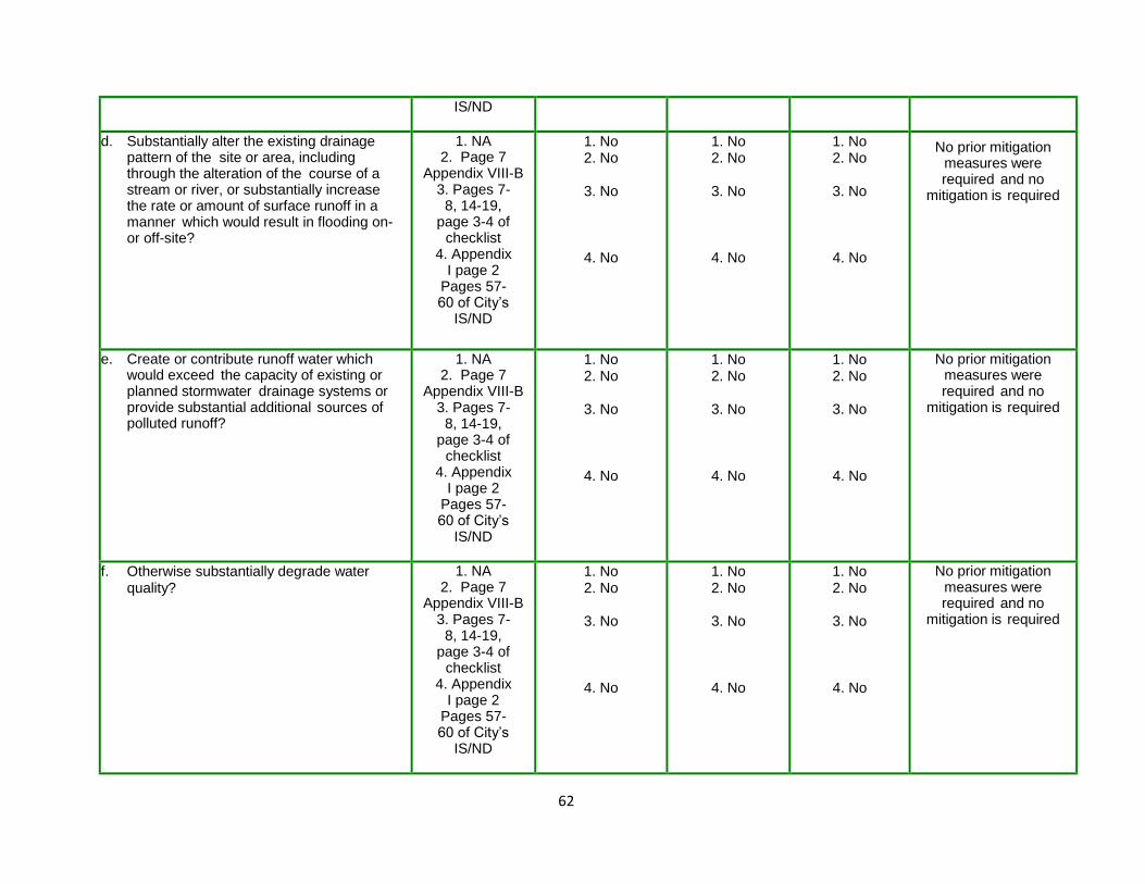
62
IS/ND
d. Substantially alter the existing drainage pattern of the site or area, including through the alteration of the course of a stream or river, or substantially increase the rate or amount of surface runoff in a manner which would result in flooding on- or off-site?
1. NA 2. Page 7
Appendix VIII-B 3. Pages 7-
8, 14-19, page 3-4 of
checklist 4. Appendix
I page 2 Pages 57-60 of City’s
IS/ND
1. No 2. No
3. No
4. No
1. No 2. No
3. No
4. No
1. No 2. No
3. No
4. No
No prior mitigation measures were required and no
mitigation is required
e. Create or contribute runoff water which would exceed the capacity of existing or planned stormwater drainage systems or provide substantial additional sources of polluted runoff?
1. NA 2. Page 7
Appendix VIII-B 3. Pages 7-
8, 14-19, page 3-4 of
checklist 4. Appendix
I page 2 Pages 57-60 of City’s
IS/ND
1. No 2. No
3. No
4. No
1. No 2. No
3. No
4. No
1. No 2. No
3. No
4. No
No prior mitigation measures were required and no
mitigation is required
f. Otherwise substantially degrade water quality?
1. NA 2. Page 7
Appendix VIII-B 3. Pages 7-
8, 14-19, page 3-4 of
checklist 4. Appendix
I page 2 Pages 57-60 of City’s
IS/ND
1. No 2. No
3. No
4. No
1. No 2. No
3. No
4. No
1. No 2. No
3. No
4. No
No prior mitigation measures were required and no
mitigation is required

63
g. Place housing within a 100-year flood hazard area as mapped on a federal Flood Hazard Boundary or Flood Insurance Rate Map or other flood hazard delineation map?
NA 1. No 2. No 3. No 4. No
1. No 2. No 3. No 4. No
1. No 2. No 3. No 4. No
No prior mitigation measures were required and no
mitigation is required
h. Place within a 100-year flood hazard area structures which would impede or redirect flood flows?
1. NA 2. Page 7
Appendix VIII-B 3. Pages 7-
8, 14-19, page 3-4 of
checklist 4. Appendix
I page 2 Pages 57-60 of City’s
IS/ND
1. No 2. No
3. No
4. No
1. No 2. No
3. No
4. No
1. No 2. No
3. No
4. No
No prior mitigation measures were required and no
mitigation is required
i. Expose people or structures to a significant risk of loss, injury or death involving flooding, including flooding as a result of the failure of a levee or dam?
1. NA 2. Page 7
Appendix VIII-B 3. Pages 7-
8, 14-19, page 3-4 of
checklist 4. Appendix
I page 2 Pages 57-60 of City’s
IS/ND
1. No 2. No
3. No
4. No
1. No 2. No
3. No
4. No
1. No 2. No
3. No
4. No
No prior mitigation measures were required and no
mitigation is required
j. Inundation by seiche, tsunami, or mudflow? 1. NA 2. Page 7
Appendix VIII-B 3. Pages 7-
8, 14-19, page 3-4 of
checklist 4. Appendix
I page 2 Pages 57-
1. No 2. No
3. No
4. No
1. No 2. No
3. No
4. No
1. No 2. No
3. No
4. No
No prior mitigation measures were required and no
mitigation is required

64
60 of City’s IS/ND
Discussion:
1, 2, 3, and 4.
a) The Project site is located within the jurisdiction of the Los Angeles RWQCB. The RWQCB protects ground and surface water quality in the Los Angeles Region, including the coastal watersheds of Los Angeles and Ventura Counties, along with very small portions of Kern and Santa Barbara Counties. An existing LARWQCB Waste Discharge Permit (WDR) for the CPS pilot test will be updated to include future CPS based remediation, as necessary.
The Facility is also under the jurisdiction of the Sanitation District of Los Angeles County (SDLAC). Any business that desires to discharge industrial wastewater to the Districts' sewerage system must first obtain an Industrial Wastewater Discharge Permit. The Facility operates under an existing Industrial Wastewater Discharge Permit (Permit No. 21498), which was issued June 10, 2014, and expires June 9, 2019. Industrial wastewater is defined as all wastewater from any manufacturing, processing, institutional, commercial, or agricultural operation or any operation where the wastewater discharged includes significant quantities of waste of non-human origin.
Ongoing facility operations or additional activities associated with the closure of Pond 1 are not expected to require a new or amended permit from LARWQCB or SDLAC. Therefore, the projects should not violate any water quality standards or waste discharge requirements.
b) None of the Project activities require extraction of groundwater or will affect recharge of groundwater. The purpose of the CPS injections to the subsurface is to reduce hexavalent chromium to trivalent chromium and fixate total chromium in soil and groundwater.
c, d, e) In regards to drainage patterns and runoff, the City of Santa Fe Springs, in their 2008 IS/ND for the proposed oily water waste treatment system, stated the following:
“…..all projects must conform to Chapter 52 of the City Code, and implement the requirements of the approved Standard Urban Stormwater Mitigation Plan (SUSMP). The SUSMP includes a requirement to implement post construction Best Management Practices (BMPs) to mitigate (infiltrate and treat) the first three-quarters of an inch (3/4”) of runoff from all storm events and to control peak flow discharges. All onsite storm systems and filters shall be maintained by the property owner.
Moreover, if drainage becomes an issue on the subject property as a result of the use, the owner/operator would be required to submit a drawing to the City Engineer for approval, showing the proposed plan and profile of onsite storm drain systems to minimize the impact that have occurred. Such drawing must be prepared by a Registered Civil Engineer. Upon completion, the owner/developer will also be required to submit a record drawing, or “As-Built” for approval by the City Engineer. If necessary, the owner/developer will also be required to submit to the City Engineer any drainage covenants, private easement documents, or reciprocal drainage provisions for cross-lot drainage flows to be recorded in the Office of the County Recorder.
Therefore, because of the methods and programs mentioned above, project implementation should not result in substantial erosion or siltation either on or off-site, nor will it cause a substantial increase to the rate or amount of surface runoff in a manner that would result in flooding on-or-off-site. Although the subject use may create or contribute runoff water, the runoff is not expected to exceed the capacity of the existing or planned storm water drain age system.”
The Project site is entirely paved or covered with concrete. The Facility has been contoured to direct all storm water to one of two collection sumps

65
(maintenance sump at east end of facility and street sump at middle of facility), where runoff is collected and then either used in onsite processes or treated through the onsite wastewater treatment system and discharged to the SDLAC treatment plant. The wastewater treatment system is located in the former Pond 1 structure, and thus, in order for closure of Pond 1 to occur, this system, consisting of wastewater treatment tanks, must be relocated elsewhere on the Project site. However, these relocated tanks would be designed to have the same treatment capacity as under the existing conditions. Additionally, the Project would not alter the existing drainage pattern of the Project site, will not increase the percentage of impervious surface onsite, or affect either the volume or rate of storm water flows onsite. Thus, the Project would not increase the amount of storm water runoff originating onsite.
f) In regards to groundwater quality, the Site is completely paved and all permitted and proposed hazardous waste management units at the facility require some form of secondary containment to protect from spills. CPS injections proposed in the Interim Measure Work Plan are to remediate contaminated soils, which reduce risk of contamination to groundwater. The injections also require a Waste Discharge Permit from the California Regional Water Quality Control Board Los Angeles Region (LARWQCB). Therefore, project activities are not anticipated to substantially degrade water quality.
g, h, i, j) According to the Flood Rate Insurance Map (Panel #060158) published by the Federal Emergency Management Agency, the Facility is not located within a 100- and 500-year flood hazard area. The Facility is also not located near any dams or levees and is not at risk from being damaged by a seiche, tsunami, or mudflow.
No new circumstances or project changes have occurred nor has any substantially important new information been found requiring new analysis or verification. Therefore, the conclusions of the prior Negative Declaration(s) remain valid and the proposed activities would not result in new or substantially more severe significant impacts to hydrology and water quality.
References
City of Santa Fe Springs. Initial Study and Negative Declaration. Reconsideration of Conditional Use Permit Case No. 441. Phibro-Tech. October 2008.
DUDEK. Environmental Information Form. Phibro-Tech, Santa Fe Springs, California. May 29, 2015
Sanitation Districts of Los Angeles County. ND. Information and Instructions for Obtaining an Industrial Waste Discharge Permit Webpage.
Environmental Resource
Where Impact Was Analyzed in
Prior Environmental
Documents.
Do Proposed Changes Involve New Significant
Impacts or Substantially More Severe
Impacts?
Any New Circumstances Involving New
Significant Impacts or Substantially
More Severe Impacts?
Any New Information Requiring
New Analysis or
Verification?
Prior Environmental
Documents Mitigations
Implemented or Address Impacts
10. LAND USE AND PLANNING. Would the project:
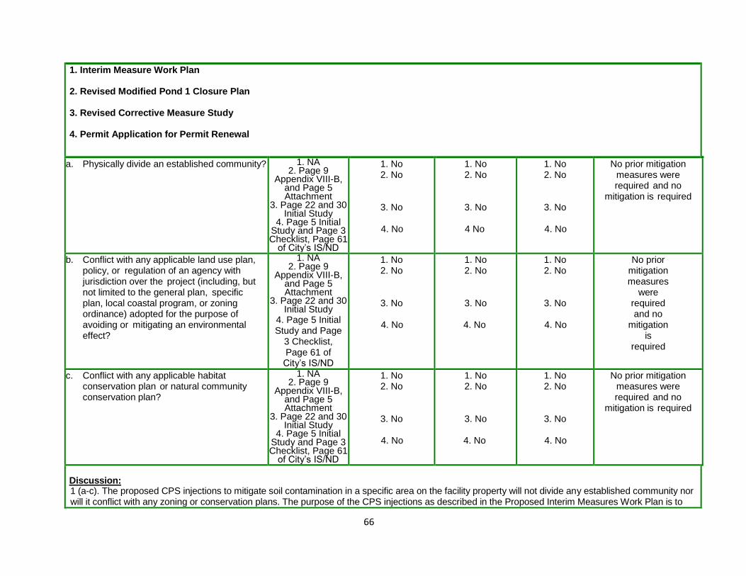
66
1. Interim Measure Work Plan 2. Revised Modified Pond 1 Closure Plan 3. Revised Corrective Measure Study 4. Permit Application for Permit Renewal
a. Physically divide an established community? 1. NA 2. Page 9
Appendix VIII-B, and Page 5 Attachment
3. Page 22 and 30 Initial Study
4. Page 5 Initial Study and Page 3 Checklist, Page 61
of City’s IS/ND
1. No 2. No
3. No
4. No
1. No 2. No
3. No
4 No
1. No 2. No
3. No
4. No
No prior mitigation measures were required and no
mitigation is required
b. Conflict with any applicable land use plan, policy, or regulation of an agency with jurisdiction over the project (including, but not limited to the general plan, specific plan, local coastal program, or zoning ordinance) adopted for the purpose of avoiding or mitigating an environmental effect?
1. NA 2. Page 9
Appendix VIII-B, and Page 5 Attachment
3. Page 22 and 30 Initial Study
4. Page 5 Initial Study and Page
3 Checklist, Page 61 of City’s IS/ND
1. No 2. No
3. No
4. No
1. No 2. No
3. No
4. No
1. No 2. No
3. No
4. No
No prior mitigation measures
were required and no
mitigation is
required
c. Conflict with any applicable habitat conservation plan or natural community conservation plan?
1. NA 2. Page 9
Appendix VIII-B, and Page 5 Attachment
3. Page 22 and 30 Initial Study
4. Page 5 Initial Study and Page 3 Checklist, Page 61
of City’s IS/ND
1. No 2. No
3. No
4. No
1. No 2. No
3. No
4. No
1. No 2. No
3. No
4. No
No prior mitigation measures were required and no
mitigation is required
Discussion: 1 (a-c). The proposed CPS injections to mitigate soil contamination in a specific area on the facility property will not divide any established community nor will it conflict with any zoning or conservation plans. The purpose of the CPS injections as described in the Proposed Interim Measures Work Plan is to

67
treat hexavalent chromium impacted vadose zone soils in an area onsite. The PTI facility is zoned M-2, Heavy Manufacturing and none of the activities will occur outside the facility boundary. As discussed under Environmental Resource #4 (above), there are no known biological resources at the facility and would therefore not conflict with any conservation plan established by the City of Santa Fe Springs or any other public agency. 2 (a-c). All soil excavation and demolition activities associated with the closure of Pond 1 will occur onsite and will not physically divide any established neighborhood. The purpose of the project is to complete closure of the former surface impoundment, which is currently being used as a secondary containment structure for two 30,000-gallon wastewater tanks (W-1 and W-2). The closure will not change the current zoning status of the property, which is M-2, Heavy Manufacturing and there are no known biological resources at the facility so there would not be any conflicts with any conservation plan established by the City of Santa Fe Springs or any other public agency. 3 (a-c). The purpose of the CMS was to evaluate groundwater remediation alternatives and the study proposed CPS injections as a remedy to replace groundwater pump and treat (P&T), the remedy prescribed as in the Permit as modified by DTSC in 1995. To support the decision to modify the permit in 1995, DTSC completed an Initial Study, which concluded that there would be no alteration of present or planned land use because the project is located in a designed industrial zone and the corrective action will not change that zone's usage or purpose. The selection of CPS as an alternative to groundwater P&T would not change this determination. 4(a-c). PTI is requesting in their current permit application to continue their current operations and make several changes by adding and upgrading certain tanks, storage areas, equipment, etc. The most significant change to their operation is the addition of a new treatment system (Area O) to treat oily wastewater, which is a hazardous waste not currently managed at the facility. This proposed process required Reconsideration of CUP Case No. 441 by the City of Santa Fe Springs. The City determined in their 2008 Initial Study that there would be no impacts to land use from treating oily wastewater at the facility. The Initial Study stated the following:
“…project implementation will not divide an established community or disrupt patterns of community life. The proposed project is for an industrial use within an industrial area of the city. In addition, the applicant is required to obtain approval for the requested Conditional Use Permit (CUP), as well as any other required, local, state, or federal permits before the owner may begin operations of the oily wastewater operation on the subject site. In processing the CUP entitlement, staff will be reviewing the project to ensure that it will not conflict with any applicable land use plan, policy, or regulation of an agency with jurisdiction over the project (including, but not limited to the general plan, local coastal program, or zoning ordinance).”
The City of Santa Fe Springs has stated that they do not consider CUP 441 “as having expired”
19 and that “there are no actions currently pending with
the SFS (Santa Fe Springs) Planning Commission, or other City board, with respect to CUP Case No. 441… The City of Santa Fe Springs does not regard said CUP, as "Reconsidered" (or amended) in 2009, as having expired.”
20 Because the additional changes the facility is requesting to their
operations do not require further reconsideration of the CUP 441 and do not alter the property’s zoning designation, there would be no impacts to the existing land use and no further analysis is necessary.
19
Email from Steve Skolnik, City Attorney, Santa Fe Springs, to Erika Giorgi, Attorney, DTSC Office of Legal Affairs, March 18, 2015. 20
Email from Steve Skolnik, City Attorney, Santa Fe Springs, to Erika Giorgi, Attorney, DTSC Office of Legal Affairs, March 18, 2015.

68
Environmental Resource
Where Impact Was Analyzed in
Prior Environmental
Documents.
Do Proposed Changes Involve New Significant
Impacts or Substantially More Severe
Impacts?
Any New Circumstances Involving New
Significant Impacts or Substantially
More Severe Impacts?
Any New Information Requiring
New Analysis or
Verification?
Prior Environmental
Documents Mitigations
Implemented or Address Impacts
11. MINERAL RESOURCES. Would the Project: 1. Interim Measure Workplan 2. Modified Pond 1 Closure Plan 3. Draft CMS 4. Permit Renewal
a. Result in the loss of availability of a known mineral resource that would be of value to the region and the residents of the state?
1.NA 2. NA 3. NA 4. Page 62 City IS/ND
1. No 2. No 3. No 4. No
1. No 2. No 3. No 4. No
1. No 2. No 3. No 4. No
No prior mitigation measures were required and no
mitigation is required
b. Result in the loss of availability of a locally-important mineral resource recovery site delineated on a local general plan, specific plan or other land use plan?
1. NA 2. NA 3. NA 4. Page 62 City IS/ND
1. No 2. No 3. No 4. No
1. No 2. No 3. No 4. No
1. No 2. No 3. No 4. No
No prior mitigation measures were required and no
mitigation is required
Discussion:
1, 2, 3, 4 (a-b). Los Angeles County depends on the California Geological Survey to identify deposits of regionally-significant aggregate resources. These clusters or belts of mineral deposits are designated as Mineral Resource Zones (MRZ-2s). The Draft March 2015 Los Angeles County General Plan, Figure 9.6, shows that the facility is not located within any MRZ-2s. Therefore, project activities are not likely to impact mineral any resources and no further analysis is necessary.
Reference
Department of Regional Planning. http://planning.lacounty.gov/assets/upl/project/gp_2035_2014-FIG_9-6_mineral_resources.pdf May, 2014.

69
Accessed August 2015
Environmental Resource
Where Impact Was Analyzed in
Prior Environmental
Documents.
Do Proposed Changes Involve New Significant
Impacts or Substantially More Severe
Impacts?
Any New Circumstances Involving New
Significant Impacts or Substantially
More Severe Impacts?
Any New Information Requiring
New Analysis or
Verification?
Prior Environmental
Documents Mitigations
Implemented or Address Impacts
12. NOISE. Would the project result in: 1. Interim Measure Work Plan 2. Revised Modified Pond 1 Closure Plan 3. Revised Corrective Measure Study 4. Permit Application for Permit Renewal
a. Exposure of persons to or generation of noise levels in excess of standards established in the local general plan or noise ordinance, or applicable standards of other agencies?
1. NA 2. Page 4
Attachment to Checklist 3. Page 25
and 29 4. Page 2
Appendix I and Page 63 City’s IS/ND
1.No 2.No
3. No
4. No
1. No 2. No
3. No
4. No
1. No 2. No
3. No
4. No
No prior mitigation measures were required and no
mitigation is required
b. Exposure of persons to or generation of excessive groundborne vibration or groundborne noise levels?
1. NA 2. Page 4
Attachment to Checklist 3. Page 25
and 29 4. Page 2
Appendix I and Page 63 City’s
1. No 2. No
3. No
4. No
1. No 2. No
3. No
4. No
1. No 2. No
3. No
4. No
No prior mitigation measures were required and no
mitigation is required

70
IS/ND
c. A substantial permanent increase in ambient noise levels in the project vicinity above levels existing without the project?
1. NA 2. Page 4
Attachment to Checklist 3. Page 25
and 29 4. Page 2
Appendix I and Page 63 City’s IS/ND
1. No 2. No
3. No
4. No
1. No 2. No
3. No
4. No
1. No 2. No
3. No
4. No
No prior mitigation measures were required and no
mitigation is required
d. A substantial temporary or periodic increase in ambient noise levels in the project vicinity above levels existing without the project?
1. NA 2. Page 4
Attachment to Checklist 3. Page 25
and 29 4. Page 2
Appendix I and Page 63
1. No 2. No
3. No
4. No
1. No 2. No
3. No
4. No
1. No 2. No
3. No
4. No
No prior mitigation measures were required and no
mitigation is required
e. For a project located within an airport land use plan or, where such a plan has not been adopted, within two miles of a public airport or public use airport, would the project expose people residing or working in the project area to excessive noise levels?
NA NA NA NA No prior mitigation measures were required and no
mitigation is required
f. For a project within the vicinity of a private airstrip, would the project expose people residing or working in the project area to excessive noise levels?
NA
NA
NA
NA
No prior mitigation measures were required and no
mitigation is required
Discussion: 1, 2, 3, and 4 (a-d). Previous CEQA documents indicated that noise impacts would be less than significant. Future and current operations are the same or essentially the same as those evaluated. PTI included a noise analysis in their Environmental Information Form submitted to DTSC on 5/29/2015. The analysis included noise level measurements that were taken from various locations on the facility property. Time Weighted Averages (TWA) were between 79.7 dBA and 57.5 dBA. Noise measurements taken along the facility’s northern boundary, which is closest to the nearest residential receptors located approximately 550 feet (facility fence line to residential property line) to the north, were in the 68.7 to 68.9 dBA range.

71
The following noise level table is from City of Santa Fe Springs Code of Ordinances section 155.424(E):
A-Weighted Sound Level in Decibels (dB(A))
Daytime
(7:00 a.m. to 10:00 p.m.)
Nighttime
(10:00 p.m. to 7:00 a.m.)
Maximum Cumulative Minutes
Duration in Any 1-Hour Period
Absolute
Maximum
Maximum Cumulative Minutes Duration
in Any 1-Hour Period
Absolute
Maximum
Receiving Area 30 15 5 1 30 15 5 1
Outdoor Noise
at Lot Line Of:
Any school,
church or
hospital
45 50 55 60 65 45 50 55 60 65
Any other use
In the A-1, R-1
or R-3 Zone
50 55 60 65 70 45 50 55 60 65
In the C-1 or C-4
Zone
60 65 70 75 80 55 60 65 70 75
1 In the ML, PF
or BP Zone
60 65 70 75 80 60 65 70 75 80
In the M-1 or M-
2 Zone
70 75 80 85 90 70 75 80 85 90
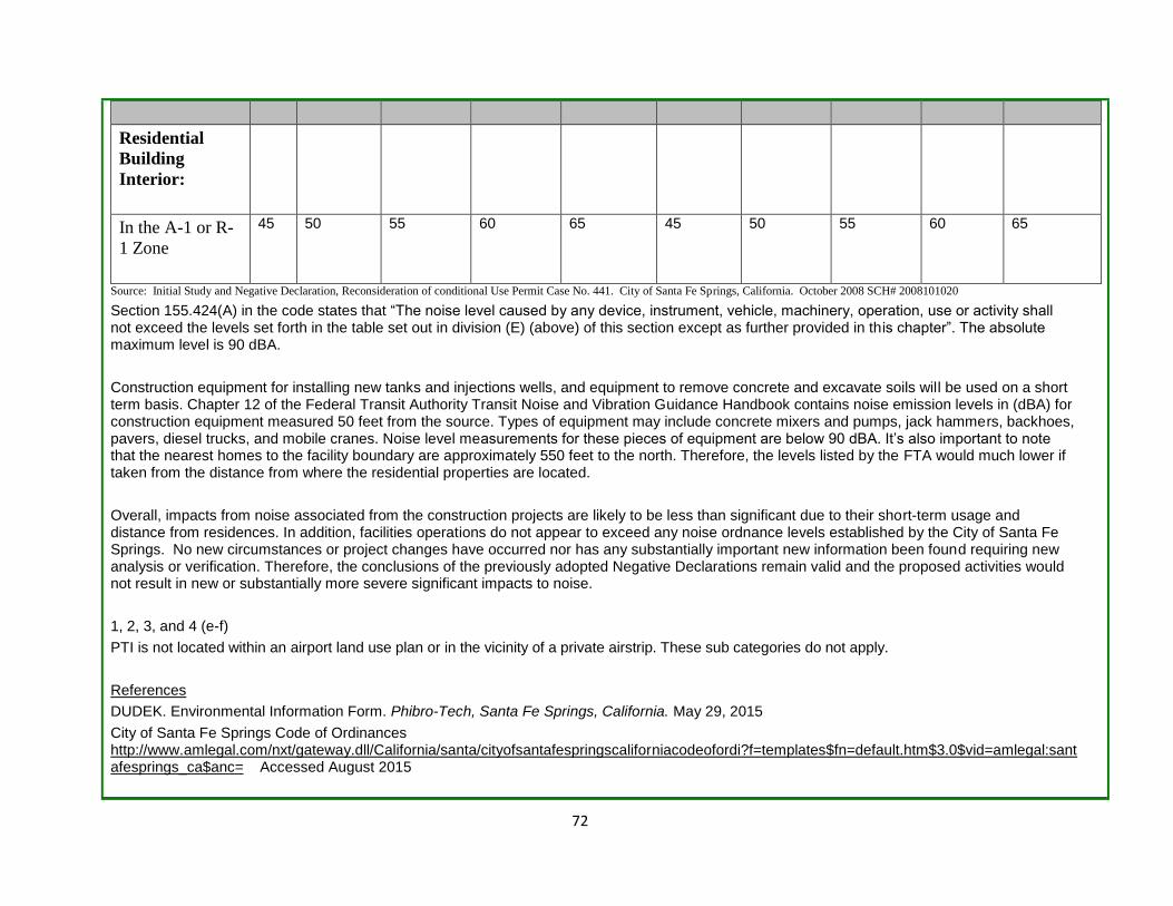
72
Residential
Building
Interior:
In the A-1 or R-
1 Zone
45 50 55 60 65 45 50 55 60 65
Source: Initial Study and Negative Declaration, Reconsideration of conditional Use Permit Case No. 441. City of Santa Fe Springs, California. October 2008 SCH# 2008101020
Section 155.424(A) in the code states that “The noise level caused by any device, instrument, vehicle, machinery, operation, use or activity shall not exceed the levels set forth in the table set out in division (E) (above) of this section except as further provided in this chapter”. The absolute maximum level is 90 dBA.
Construction equipment for installing new tanks and injections wells, and equipment to remove concrete and excavate soils will be used on a short term basis. Chapter 12 of the Federal Transit Authority Transit Noise and Vibration Guidance Handbook contains noise emission levels in (dBA) for construction equipment measured 50 feet from the source. Types of equipment may include concrete mixers and pumps, jack hammers, backhoes, pavers, diesel trucks, and mobile cranes. Noise level measurements for these pieces of equipment are below 90 dBA. It’s also important to note that the nearest homes to the facility boundary are approximately 550 feet to the north. Therefore, the levels listed by the FTA would much lower if taken from the distance from where the residential properties are located.
Overall, impacts from noise associated from the construction projects are likely to be less than significant due to their short-term usage and distance from residences. In addition, facilities operations do not appear to exceed any noise ordnance levels established by the City of Santa Fe Springs. No new circumstances or project changes have occurred nor has any substantially important new information been found requiring new analysis or verification. Therefore, the conclusions of the previously adopted Negative Declarations remain valid and the proposed activities would not result in new or substantially more severe significant impacts to noise.
1, 2, 3, and 4 (e-f)
PTI is not located within an airport land use plan or in the vicinity of a private airstrip. These sub categories do not apply.
References
DUDEK. Environmental Information Form. Phibro-Tech, Santa Fe Springs, California. May 29, 2015
City of Santa Fe Springs Code of Ordinances http://www.amlegal.com/nxt/gateway.dll/California/santa/cityofsantafespringscaliforniacodeofordi?f=templates$fn=default.htm$3.0$vid=amlegal:santafesprings_ca$anc= Accessed August 2015

73
United States Department of Transportation, Federal Highway Administration, Office of Planning, Environment, and Realty – Highway Traffic Noise
http://www.fhwa.dot.gov/environment/noise/construction_noise/handbook/handbook09.cfm Accessed August 2015
Environmental Resource
Where Impact Was Analyzed in
Prior Environmental
Documents.
Do Proposed Changes Involve New Significant
Impacts or Substantially More Severe
Impacts?
Any New Circumstances Involving New
Significant Impacts or Substantially
More Severe Impacts?
Any New Information Requiring
New Analysis or
Verification?
Prior Environmental
Documents Mitigations
Implemented or Address Impacts
13. POPULATION AND HOUSING. Would the Project: 1. Interim Measure Work Plan 2. Revised Modified Pond 1 Closure Plan 3. Revised Corrective Measure Study 4. Permit Application for Permit Renewal
a. Induce substantial population growth in an area, either directly (for example, by proposing new homes and businesses) or indirectly (for example, through extension of roads or other infrastructure)?
1. NA 2. page 9 Appendix VIII-B
3. Page 32 4. Page 4 Environmental Checklist, and page 65
1. No 2. No
3. No 4. No
1. No 2. No
3. No 4. No
1. No 2. No
3. No 4. No
No prior mitigation measures were required and no
mitigation is required
b. Displace substantial numbers of existing housing, necessitating the construction of replacement housing elsewhere?
1. NA 2. page 9 Appendix VIII-B 3. Page 32 4. Page 4 Environmental Checklist, and
1. No 2. No
3. No 4. No
1. No 2. No
3. No 4. No
1. No 2. No
3. No 4. No
No prior mitigation measures were required and no
mitigation is required

74
page 65
c. Displace substantial numbers of people, necessitating the construction of replacement housing elsewhere?
1. NA 2. page 9 Appendix VIII-B 3. Page 32 4. Page 4 Environmental Checklist, and page 65
1. No 2. No
3. No 4. No
1. No 2. No
3. No 4. No
1. No 2. No
3. No 4. No
No prior mitigation measures were required and no
mitigation is required
Discussion:
1, 2, 3, and 4 (a-c). All previous CEQA documents indicated no impacts to population growth or housing from construction activities or operation of the facility. The current project activities involve the renewal of a hazardous waste facility permit, closure of a surface impoundment and various corrective actions. All project activities will occur within the facility property. No additional housing or replacement housing is required, nor will the proposed activities induce population growth. Therefore, no further analysis is necessary.
Environmental Resource
Where Impact Was Analyzed in
Prior Environmental
Documents.
Do Proposed Changes Involve New Significant
Impacts or Substantially More Severe
Impacts?
Any New Circumstances Involving New
Significant Impacts or Substantially
More Severe Impacts?
Any New Information Requiring
New Analysis or
Verification?
Prior Environmental
Documents Mitigations
Implemented or Address Impacts
14. PUBLIC SERVICES. Would the project: 1. Interim Measure Work Plan 2. Revised Modified Pond 1 Closure Plan 3. Revised Corrective Measure Study 4. Permit Application for Permit Renewal
a. Result in substantial adverse physical impacts associated with the provision of
1. NA 2. page 9
1.No 2. No
1. No 2. No
1. No 2. No
No prior mitigation measures were

75
new or physically altered governmental facilities, need for new or physically altered governmental facilities, the construction of which could cause significant environmental impacts, in order to maintain acceptable service ratios, response times or other performance objectives for any of the public services:
Appendix VIII-B 3. Page 32 4. Page 5 Environmental Checklist, Page 66-67 City IS/ND
3. No 4. No
3. No 4. No
3. No 4. No
required and no mitigation is required
Fire protection?
1. No 2. No 3. No 4. No
1. No 2. No 3. No 4. No
1. No 2. No 3. No 4. No
No prior mitigation measures were required and no
mitigation is required
Police protection? 1. No 2. No 3. No 4. No
1. No 2. No 3. No 4. No
1. No 2. No 3. No 4. No
No prior mitigation measures were required and no
mitigation is required
Schools? 1. No 2. No 3. No 4. No
1. No 2. No 3. No 4. No
1. No 2. No 3. No 4. No
No prior mitigation measures were required and no
mitigation is required
Parks? 1. No 2. No 3. No 4. No
1. No 2. No 3. No 4. No
1. No 2. No 3. No 4. No
No prior mitigation measures were required and no
mitigation is required
Other public facilities?
1. No 2. No 3. No 4. No
1. No 2. No 3. No 4. No
1. No 2. No 3. No 4. No
No prior mitigation measures were required and no
mitigation is required

76
Discussion: 1, 2, 3, and 4 (a). Previous CEQA documents concluded that there would no impacts to existing public services such as police, fire, and schools, nor would the project require new services in the area, except for the City of Santa Fe Springs 2008 IS/ND. In that document, the City stated there would be a less than significant impact, but did not provide any detailed explanation as to why. The projects would not change the existing land use for the site and there are no known provisions for new or physically altered governmental facilities or need to alter any existing governmental facilities. Fire and crime protection services are provided by the City and calls for service are not expected to increase after implementation of the proposed activities. Therefore, no impacts on public services are expected and no further analysis is necessary. References DUDEK. Environmental Information Form. Phibro-Tech, Santa Fe Springs, California. May 29, 2015
Environmental Resource
Where Impact Was Analyzed in
Prior Environmental
Documents.
Do Proposed Changes Involve New Significant
Impacts or Substantially More Severe
Impacts?
Any New Circumstances Involving New
Significant Impacts or Substantially
More Severe Impacts?
Any New Information Requiring
New Analysis or
Verification?
Prior Environmental
Documents Mitigations
Implemented or Address Impacts
15. RECREATION. Would the project: 1. Interim Measure Work Plan 2. Revised Modified Pond 1 Closure Plan 3. Revised Corrective Measure Study 4. Permit Application for Permit Renewal
a. Increase the use of existing neighborhood and regional parks or other recreational facilities such that substantial physical deterioration of the facility would occur or be accelerated?
1. NA 2. page 11 Appendix VIII-B 3. Page 33 4. Page 6 Environmental Checklist, Page 68City IS/ND
1. No 2. No
3. No 4. No
1. No 2. No
3. No 4. No
1. No 2.No
3. No 4. No
No prior mitigation measures were required and no
mitigation is required

77
b. Include recreational facilities or require the construction or expansion of recreational facilities which might have an adverse physical effect on the environment?
1. No 2. No 3. No 4. No
1. No 2. No 3. No 4. No
1. No 2. No 3. No 4. No
No prior mitigation measures were required and no
mitigation is required
Discussion: 1, 2, 3, and 4 (a, b).
All previous CEQA documents concluded there to be no impacts on existing recreational facilities nor would any additional recreational facilities need to be constructed. The facility is located in an area zoned M-2, Heavy Manufacturing and the permit renewal, and construction, closure, and interim measure activities will occur on the facility property. No impacts to parks or recreational facilities are anticipated and no further analysis is necessary.
Environmental Resource
Where Impact Was Analyzed in
Prior Environmental
Documents.
Do Proposed Changes Involve New Significant
Impacts or Substantially More Severe
Impacts?
Any New Circumstances Involving New
Significant Impacts or Substantially
More Severe Impacts?
Any New Information Requiring
New Analysis or
Verification?
Prior Environmental
Documents Mitigations
Implemented or Address Impacts
16. TRANSPORTATION/TRAFFIC. Would the project: 1. Interim Measure Work Plan 2. Revised Modified Pond 1 Closure Plan 3. Revised Corrective Measure Study 4. Permit Application for Permit Renewal
a. Conflict with an applicable plan, ordinance or policy establishing measures of effectiveness for the performance of the circulation system, taking into account all modes of transportation including mass transit and
1. NA 2. page 10
Appendix VIII-B, page 10
Attachment to Checklist
1. No 2. No
1. No 2. No
1. No 2. No
No prior mitigation measures were required and no
mitigation is required
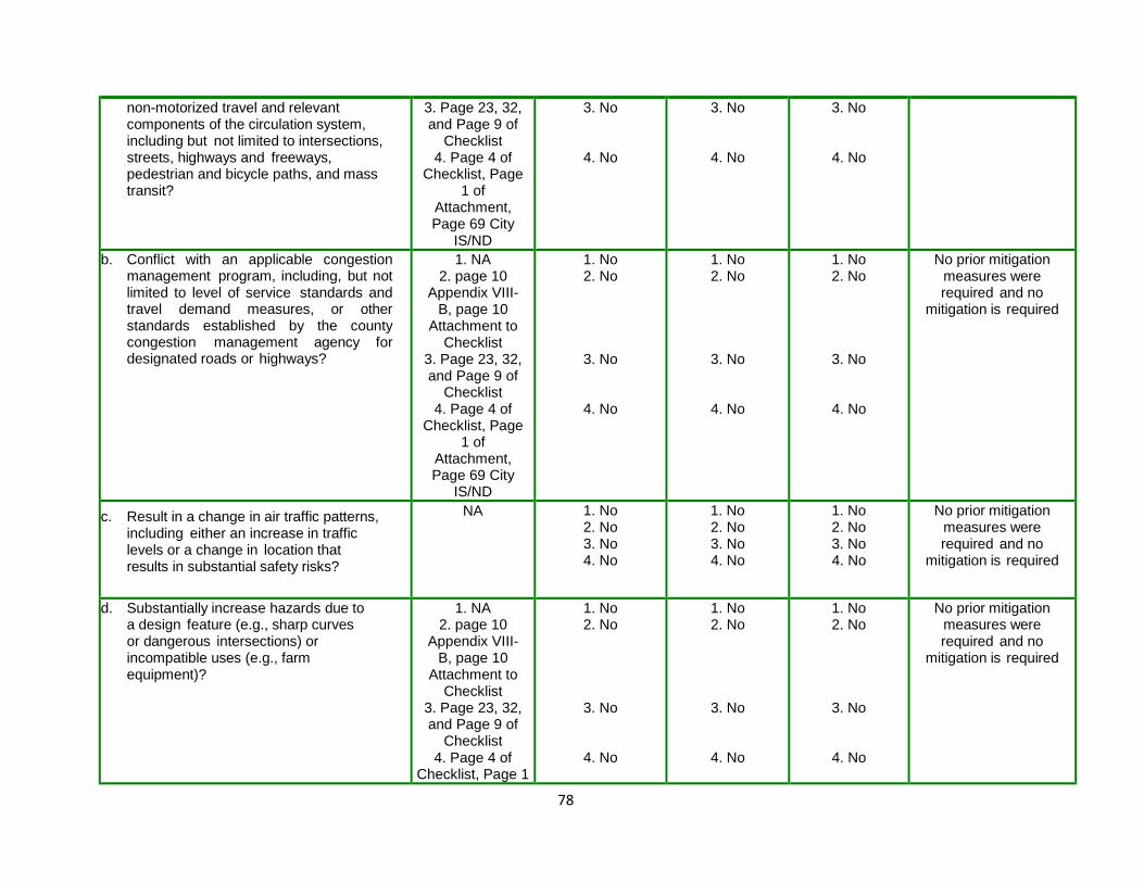
78
non-motorized travel and relevant components of the circulation system, including but not limited to intersections, streets, highways and freeways, pedestrian and bicycle paths, and mass transit?
3. Page 23, 32, and Page 9 of
Checklist 4. Page 4 of
Checklist, Page 1 of
Attachment, Page 69 City
IS/ND
3. No
4. No
3. No
4. No
3. No
4. No
b. Conflict with an applicable congestion management program, including, but not limited to level of service standards and travel demand measures, or other standards established by the county congestion management agency for designated roads or highways?
1. NA 2. page 10
Appendix VIII-B, page 10
Attachment to Checklist
3. Page 23, 32, and Page 9 of
Checklist 4. Page 4 of
Checklist, Page 1 of
Attachment, Page 69 City
IS/ND
1. No 2. No
3. No
4. No
1. No 2. No
3. No
4. No
1. No 2. No
3. No
4. No
No prior mitigation measures were required and no
mitigation is required
c. Result in a change in air traffic patterns, including either an increase in traffic levels or a change in location that results in substantial safety risks?
NA 1. No 2. No 3. No 4. No
1. No 2. No 3. No 4. No
1. No 2. No 3. No 4. No
No prior mitigation measures were required and no
mitigation is required
d. Substantially increase hazards due to a design feature (e.g., sharp curves or dangerous intersections) or incompatible uses (e.g., farm equipment)?
1. NA 2. page 10
Appendix VIII-B, page 10
Attachment to Checklist
3. Page 23, 32, and Page 9 of
Checklist 4. Page 4 of
Checklist, Page 1
1. No 2. No
3. No
4. No
1. No 2. No
3. No
4. No
1. No 2. No
3. No
4. No
No prior mitigation measures were required and no
mitigation is required
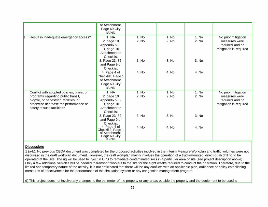
79
of Attachment, Page 69 City
IS/ND
e. Result in inadequate emergency access? 1. NA 2. page 10
Appendix VIII-B, page 10
Attachment to Checklist
3. Page 23, 32, and Page 9 of
Checklist 4. Page 4 of
Checklist, Page 1 of Attachment, Page 69 City
IS/ND
1. No 2. No
3. No
4. No
1. No 2. No
3. No
4. No
1. No 2. No
3. No
4. No
No prior mitigation measures were required and no
mitigation is required
f. Conflict with adopted policies, plans, or programs regarding public transit, bicycle, or pedestrian facilities, or otherwise decrease the performance or safety of such facilities?
1. NA 2. page 10
Appendix VIII-B, page 10
Attachment to Checklist
3. Page 23, 32, and Page 9 of
Checklist 4. Page 4 of
Checklist, Page 1 of Attachment, Page 69 City
IS/ND
1. No 2. No
3. No
4. No
1. No 2. No
3. No
4. No
1. No 2. No
3. No
4. No
No prior mitigation measures were required and no
mitigation is required
Discussion:
1 (a-b). No previous CEQA document was completed for the proposed activities involved in the Interim Measure Workplan and traffic volumes were not discussed in the draft workplan document. However, the draft workplan mainly involves the operation of a truck-mounted, direct-push drill rig to be operated at the Site. The rig will be used to inject in CPS to remediate contaminated soils in a particular area onsite (see project description above). Only a few additional vehicles will be needed to transport workers to the site for the eight weeks required to conduct the operation. Therefore, due to the limited and temporary nature of the activity, it is not anticipated that there will be any conflicts with an applicable plan, ordinance or policy establishing measures of effectiveness for the performance of the circulation system or any congestion management program.
d) This project does not involve any changes to the perimeter of the property or any areas outside the property and the equipment to be used is

80
appropriate for an area zoned HM-2, Heavy Manufacturing. Therefore, there will be no increase in hazards due to intersection designs or result in inadequate emergency access to the facility. The conclusion is no impact.
2 (a-b). The closure of Pond 1 will involve the removal of wastewater treatment tanks W-1 and W-2, the removal of the concrete containment system, and the excavation of soils to a maximum depth of ten feet below the containment system. CPS injections will then occur below 10 feet to approximately 50 feet to transform the mass of toxic hexavalent chromium in the vadose zone to the nontoxic trivalent chromium. The excavated area will then be backfilled with clean fill material and covered with an asphalt cap. The 1988 Closure Plan Negative Declaration concluded that additional traffic to remove and bring soils would occur for approximately one or two months and impacts would not be considered substantial compared with the existing traffic in the area.
The current closure plan addresses new closure regulations, new information regarding facility conditions, the proposed new treatment of groundwater and soil contamination, which could also potentially be appropriate for Pond 1, and that would allow for third-party closure of Pond 1, if required. In regards to traffic, the current plan estimates that up to 30 trucks will be used to remove contaminated soil and if soil loading takes place over two or three days, that will be only 10 to 15 trucks per day. Approximately 30 trucks may also be used to transport clean fill to the site. It states that this amount of additional traffic “is a less than significant level compared to existing car and truck traffic in the area compared with 33,703 vehicles per day traveling on the primary route of Slauson Avenue near Dice Road and 12,774 vehicles per including over 20 trucks per day at Los Nietos Road near Dice Road. (reference City of Santa Fe Springs, Reconsideration of Conditional Use Permit Case No. 441, Mitigated Negative Declaration, State Clearinghouse Number 2008101020, October 2008).” Therefore, there should be no conflicts with an applicable plan, ordinance or policy establishing measures of effectiveness for the performance of the circulation system or any congestion management program.
3(a-f). The draft Corrective Measures Study is a document that proposes to replace groundwater pump and treatment with CPS injections to remediate hexavalent chromium affected vadose zone soils and groundwater. Groundwater pump and treat was required as part of a Class III permit modification completed in 1995. DTSC completed a Negative Declaration to support the Class III permit modification decision and the Negative Declaration concluded there to be no impacts from additional vehicular movement, or on existing transportation systems and parking facilities, or alter patterns of circulation or movement of people and/or goods.
It is not anticipated that the proposal to replace groundwater pump and treat with CPS injections would change this conclusion; however, future clean up actions using CPS injections, which are currently under consideration, would require further DTSC review and approval.
4 (a, b). The PTI hazardous waste facility stores, treats, and transfers hazardous wastes. The traffic impacts from the current operations at facility were determined to be no impact (1991 IS/ND). DTSC concluded in the 1991 IS/ND that the proposed project is not expected to generate substantial additional vehicular movement. The expected volume of traffic directly related to this facility will range from the existing 12 trucks per day to a maximum of 19 trucks per day.
PTI is proposing several changes to the current operations, most notably the addition of a new treatment system for oily water waste. In 2008, the City of Santa Fe Springs completed an Initial Study/Negative Declaration, which analyzed traffic impacts transportation from operation of this treatment system. The City concluded that the 34 additional daily vehicle trips associated with the oily wastewater treatment would not cause a significant increase in traffic, nor would it be substantial in relation to the existing traffic load and capacity of the street system, and there would be no individual

81
or cumulative exceedance of the service standard established by the County. The City stated that 33,703 vehicles per day travel on the primary route of Slauson Avenue near Dice Road and the alternate route of Los Nietos Road near Dice Road handles 12,774 vehicles per day.
Other changes to current operations at the facility include several short term construction projects to install new or modify existing tank systems and storage areas. These projects will involve additional vehicles during their duration. However, they will not occur at the same time nor will they result in a permanent increase in the level of traffic already at the facility or surrounding area. Therefore, there should be no conflicts with an applicable plan, ordinance or policy establishing measures of effectiveness for the performance of the circulation system or any congestion management program.
1, 2, and 4 (c-f) c) Project activities will impact air traffic patterns. This sub category is not applicable. d) These projects do not involve any changes to the perimeter of the property or any areas outside the property and the equipment to be used is appropriate for an area zoned HM-2, Heavy Manufacturing. Therefore, there will be no substantial increase in hazards due to a design feature.
e) PTI is required to maintain a contingency plan under California Code of Regulations Title 22 Division 4.5, section 66264.51. The plan must include an evacuation plan and a description of arrangements agreed to by local police departments, fire departments, hospitals, contractors, and State and local emergency response teams to coordinate emergency services. Therefore, it is not anticipated there will be any effects to emergency evacuation plans.
f) Project activities will not conflict with applicable policies, plans, or programs supporting alternative transportation.
Environmental Resource
Where Impact Was Analyzed in
Prior Environmental
Documents.
Do Proposed Changes Involve New Significant
Impacts or Substantially More Severe
Impacts?
Any New Circumstances Involving New
Significant Impacts or Substantially
More Severe Impacts?
Any New Information Requiring
New Analysis or
Verification?
Prior Environmental
Documents Mitigations
Implemented or Address Impacts
17. UTILITIES AND SERVICE SYSTEMS. Would the project: 1. Interim Measure Work Plan 2. Revised Modified Pond 1 Closure Plan 3. Revised Corrective Measure Study 4. Permit Application for Permit Renewal
a. Exceed wastewater treatment requirements of the applicable Regional
1. NA 2. page 10
1. No 2. No
1. No 2. No
1. No 2. No
No prior mitigation measures were

82
Water Quality Control Board?
Appendix VIII-B 3. Page 25, Page 10 IS Checklist 4. page 5 Appendix VIII-B, page 72 City IS/ND
3. No
4. No
3. No
4. No
3. No
4. No
required and no mitigation is required
b. Require or result in the construction of new water or wastewater treatment facilities or expansion of existing facilities, the construction of which could cause significant environmental effects?
1. NA 2. page 10 Appendix VIII-B 3. Page 25, Page 10 IS Checklist 4. page 5 Appendix VIII-B, page 72 City IS/ND
1. No 2. No
3. No
4. No
1. No 2. No
3. No
4. No
1. No 2. No
3. No
4. No
No prior mitigation measures were required and no
mitigation is required
c. Require or result in the construction of new storm water drainage facilities or expansion of existing facilities, the construction of which could cause significant environmental effects?
1. NA 2. page 10 Appendix VIII-B 3. Page 25, Page 10 IS Checklist 4. page 5 Appendix VIII-B, page 72 City IS/ND
1. No 2. No
3. No
4. No
1. No 2. No
3. No
4. No
1. No 2. No
3. No
4. No
No prior mitigation measures were required and no
mitigation is required
d. Have sufficient water supplies available to serve the project from existing entitlements and resources, or are new or expanded entitlements needed?
1. NA 2. page 10 Appendix VIII-B 3. Page 25, Page 10 IS Checklist 4. page 5 Appendix
1. No 2. No
3. No
4. No
1. No 2. No
3. No
4. No
1. No 2. No
3. No
4. No
No prior mitigation measures were required and no
mitigation is required
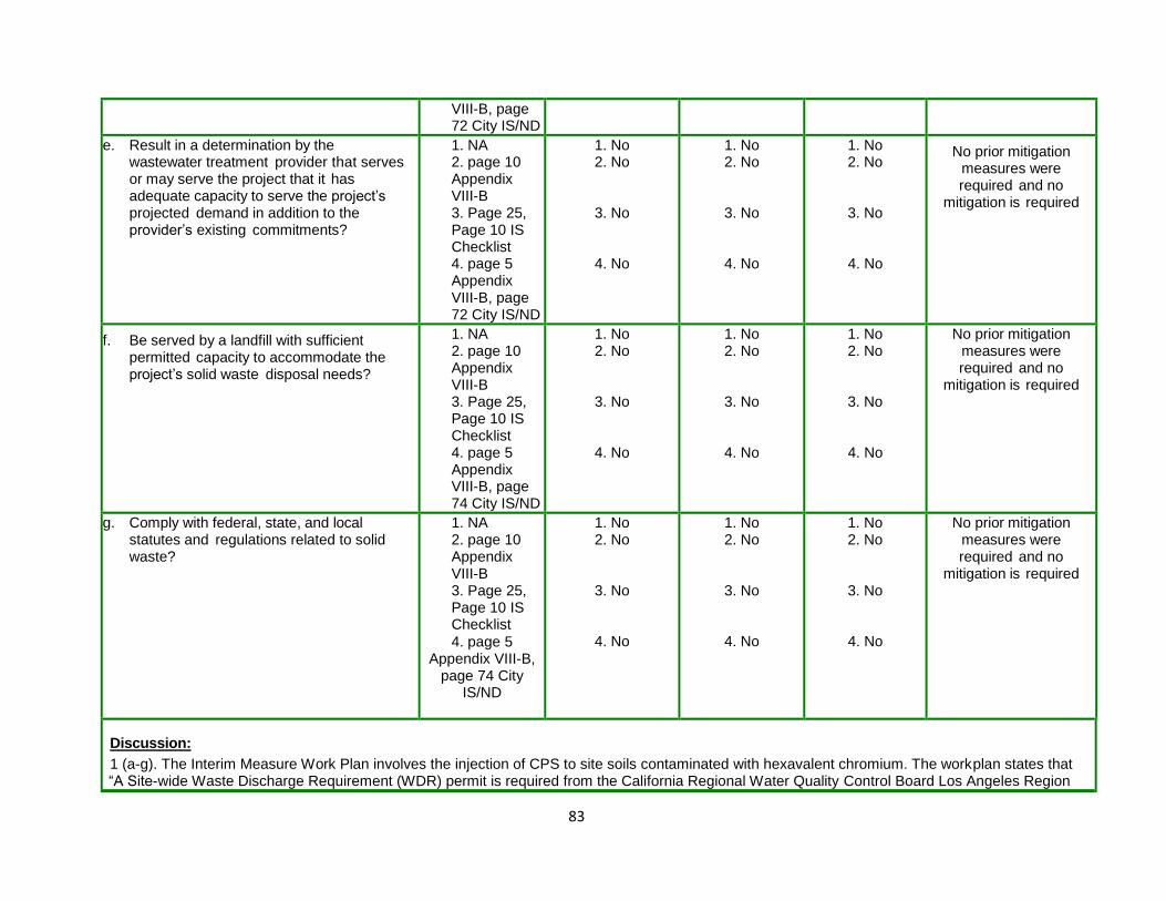
83
VIII-B, page 72 City IS/ND
e. Result in a determination by the wastewater treatment provider that serves or may serve the project that it has adequate capacity to serve the project’s projected demand in addition to the provider’s existing commitments?
1. NA 2. page 10 Appendix VIII-B 3. Page 25, Page 10 IS Checklist 4. page 5 Appendix VIII-B, page 72 City IS/ND
1. No 2. No
3. No
4. No
1. No 2. No
3. No
4. No
1. No 2. No
3. No
4. No
No prior mitigation measures were required and no
mitigation is required
f. Be served by a landfill with sufficient permitted capacity to accommodate the project’s solid waste disposal needs?
1. NA 2. page 10 Appendix VIII-B 3. Page 25, Page 10 IS Checklist 4. page 5 Appendix VIII-B, page 74 City IS/ND
1. No 2. No
3. No
4. No
1. No 2. No
3. No
4. No
1. No 2. No
3. No
4. No
No prior mitigation measures were required and no
mitigation is required
g. Comply with federal, state, and local statutes and regulations related to solid waste?
1. NA 2. page 10 Appendix VIII-B 3. Page 25, Page 10 IS Checklist
4. page 5 Appendix VIII-B,
page 74 City IS/ND
1. No 2. No
3. No
4. No
1. No 2. No
3. No
4. No
1. No 2. No
3. No
4. No
No prior mitigation measures were required and no
mitigation is required
Discussion:
1 (a-g). The Interim Measure Work Plan involves the injection of CPS to site soils contaminated with hexavalent chromium. The workplan states that “A Site-wide Waste Discharge Requirement (WDR) permit is required from the California Regional Water Quality Control Board Los Angeles Region

84
(LARWQCB) for in-situ soil and groundwater remedial activities at the Site, including in-situ chemical reduction of hexavalent chromium. Iris Environmental (PTI consultant) obtained a WDR permit from for the Pilot Test activities and is in discussions with the LARWQCB about amending the existing permit to include the interim measure activities. The LARWQCB requires that this Work Plan be approved by DTSC before a modified WDR permit can be issued.” The Interim Measure Work Plan also states that the project does not involve substantial site preparation and all soil cuttings will be drummed and disposed of following the receipt of analytical results. Any water derived from equipment decontamination procedures will be recycled on-site.
The project does not involve any expansion of wastewater treatment systems or need additional water or landfill capacity. The Facility is also under the jurisdiction of the Sanitation District of Los Angeles County (SDLAC). Any business that desires to discharge industrial wastewater to the Districts' sewerage system must first obtain an Industrial Wastewater Discharge Permit. The facility operates under an existing Industrial Wastewater Discharge Permit (Permit No. 21498), which was issued June 10, 2014, and expires June 9, 2019. Therefore, there will be no impacts to any utilities or service systems.
2 (a-g). The closure of Pond 1 will involve the removal of wastewater treatment tanks W-1 W-2, W-3, and W-4, the removal of the concrete containment system, and the excavation of soils ten feet beneath. CPS injections will then occur below 10 feet to approximately 50 feet to reduce the mass of toxic hexavalent chromium in the vadose zone to the nontoxic trivalent chromium. The excavated area will then be backfilled and covered with an asphalt cap.
Again, a WDR permit is required from the LARWQC for in-situ soil and groundwater remedial activities at the Site. It is not anticipated that the project will affect and or involve any new storm drainage systems, water supplies, or require any significant additional solid waste landfill capacity. Therefore, there will be no impacts to utilities or service systems.
3 (a-g). The Revised Corrective Measures Study is a document that proposes to replace groundwater pump and treatment with CPS injections to remediate hexavalent chromium impacted vadose zone soils and groundwater. Groundwater pump and treat was required as part of a DTSC- initiated permit modification completed in 1995. A Negative Declaration was completed by DTSC to support the DTSC initiated permit modification decision and the Negative Declaration concluded the project did not involve, address, nor result in the need for new utilities because neither new nor substantially altered utilities are required. It is not anticipated that the proposal to replace groundwater pump and treat with CPS injections would change this conclusion; however, future clean up actions using CPS injections, which are currently under consideration, would require further DTSC review and approval.
4 (a-g). The 1991 Negative Declaration completed by DTSC to support the issuance of a permit to PTI, concluded there to be no impacts to the following utilities
Natural Gas
Communication Systems
Water
Sewer or Septic Tanks

85
Storm Water Drainage
Solid Waste Disposal
The EIF completed by PTI states that the facility is under the jurisdiction of the Sanitation District of Los Angeles County (SDLAC) and operates under an existing Industrial Wastewater Discharge Permit. The facility is also under the jurisdiction of the Los Angeles RWQCB and currently the facility operations under 1991 permit do not require a permit from this agency.
The facility has its own wastewater treatment system that pretreats wastewater prior to disposal in the sanitary sewer. The permit renewal proposes to relocate and replace those tank systems with ones that are basically equivalent in size and capacity. The current permitted treatment capacity is 137,200 gallons per day and the permit renewal does not propose any increase to this limit.
Additional employees and tank systems that would be added because of the oily water waste expansion would not cause a significant increase to the current solid waste disposal or cause any significant increase in needed landfill capacity. The Facility is a fully-permitted hazardous waste treatment and storage primarily engage in the recovery of metals such a copper from metal bearing hazardous wastes. Thus, the Project reduces landfill disposal of hazardous wastes in the state’s two active and permitted disposal facilities - Clean Harbors Buttonwillow, LLC in the community of Buttonwillow, and Kettleman Hills - B18 Non-hazardous material disposal in the community of Kettleman City.
Also, in regards to solid waste disposal, the City of Santa Fe Springs stated the following in their 2008 Initial Study/Negative Declaration:
“Solid waste generated by the proposed use as well as several cities within the Los Angeles County is disposed of in a number of landfills, both County and privately owned. Sixteen facilities were identified as accepting solid waste from the City. The closest landfill (operated by the County Sanitation Districts) that could be used by the proposed project is the 1,365-acre Puente Hill Landfill. The Puente Hills Landfill is located immediately southeast of the intersection of the San Gabriel Valley (I-605) Freeway and the Pomona (SR-60) Freeway, in unincorporated Los Angeles County. The landfill operates under a local land use permit that is valid through October 31, 2013. The permit allows the landfill to accept a maximum of 13,200 tons of refuse per day. It is general knowledge that a shortfall in permitted daily landfill capacity may be experienced in the County of Los Angeles within the first decade of the 21st century.
The California Integrated Waste Management Act of 1989 (AB 939) was enacted to reduce, recycle, and reuse solid waste generated in the State to the maximum amount feasible. The Act required city and county jurisdictions to identify an implementation schedule to divert 25% of their total solid waste stream from landfill disposal by the year 1995, and 50% of the total waste stream from landfill disposal by the year 2000. In 2000, the City surpassed the mandated diversion goal. The Act also requires each city and county to promote source reduction, recycling, and safe disposal or transformation.
The City of Santa Fe Springs has prepared a Source Reduction and Recycling Element (SRRE) that identified all programs the City plans to implement to meet the mandated diversion goals. Although no new construction is anticipated from the proposed use, future developments on the subject site shall comply with Ordinance No. 914 which requires contractors to recycle materials generated on the

86
site. The required goal is to reuse or recycle 75% of the project waste. Contractors must submit a Waste Management Plan indicating the types of materials that will be recycled and the permitted Recycling Dealer. Construction and Demolition permits are not issued until the Waste Management Plan is submitted and approved. Contractor has to submit receipts or a report from the waste hauler and recycling dealer to show that 75% of the waste on site was recycled.
Further, the California Solid Waste Reuse and Recycling Access Act of 1991, as amended, require each development project to provide storage area for collection and removal of recyclable materials. All future development shall provide adequate storage areas for collection/storage of recyclable and green waste materials.
No impacts are anticipated in this regard.”
No information regarding storm drainage or current waste water entitlements to the facility have been provided in the earlier environmental documents. However, the 2008 Negative Declaration completed by the City of Santa Fe Springs concluded that existing storm drains at the perimeter of the site are adequate for current and proposed operations and that levels of service to the facility will be consistent with regional growth forecast adopted by the Southern California Association of Governments.
DTSC determined that no new circumstances or project changes have occurred nor has any substantially important new information been found requiring new analysis or verification. Therefore, the conclusions of the prior Negative Declarations remain valid and the proposed activities would not result in new or substantially more severe significant impacts to utilities.
References
City of Santa Fe Springs. Initial Study and Negative Declaration. Reconsideration of Conditional Use Permit Case No. 441. Phibro-Tech. October 2008. DUDEK. Environmental Information Form. Phibro-Tech, Santa Fe Springs, California. May 29, 2015
Environmental Resource
Where Impact
Was Analyzed in Prior
Environmental Documents.
Do Proposed Changes Involve New Significant
Impacts or Substantially More Severe
Impacts?
Any New Circumstances Involving New
Significant Impacts or Substantially
More Severe Impacts?
Any New
Information Requiring
New Analysis or
Verification?
Prior Environmental
Documents Mitigations
Implemented or Address Impacts
18. MANDATORY FINDINGS OF SIGNIFICANCE.
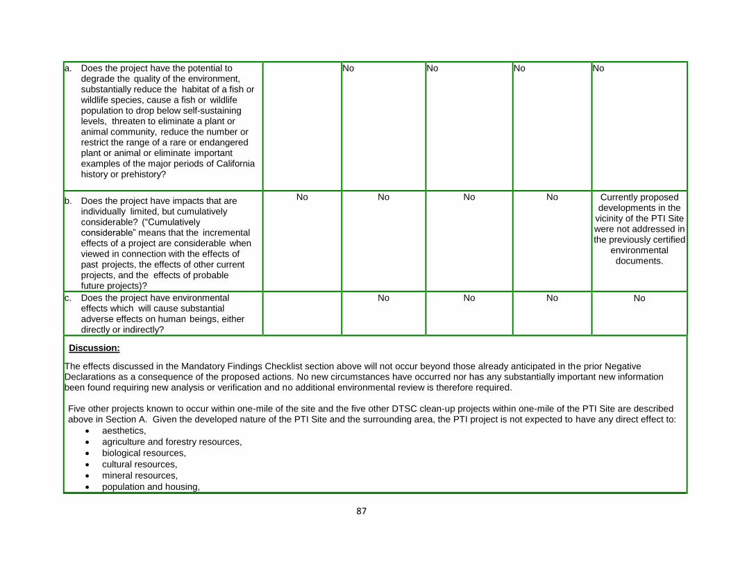
87
a. Does the project have the potential to degrade the quality of the environment, substantially reduce the habitat of a fish or wildlife species, cause a fish or wildlife population to drop below self-sustaining levels, threaten to eliminate a plant or animal community, reduce the number or restrict the range of a rare or endangered plant or animal or eliminate important examples of the major periods of California history or prehistory?
No
No
No
No
b. Does the project have impacts that are individually limited, but cumulatively considerable? (“Cumulatively considerable” means that the incremental effects of a project are considerable when viewed in connection with the effects of past projects, the effects of other current projects, and the effects of probable future projects)?
No No
No
No
Currently proposed developments in the
vicinity of the PTI Site were not addressed in the previously certified
environmental documents.
c. Does the project have environmental effects which will cause substantial adverse effects on human beings, either directly or indirectly?
No
No
No
No
Discussion:
The effects discussed in the Mandatory Findings Checklist section above will not occur beyond those already anticipated in the prior Negative Declarations as a consequence of the proposed actions. No new circumstances have occurred nor has any substantially important new information been found requiring new analysis or verification and no additional environmental review is therefore required. Five other projects known to occur within one-mile of the site and the five other DTSC clean-up projects within one-mile of the PTI Site are described above in Section A. Given the developed nature of the PTI Site and the surrounding area, the PTI project is not expected to have any direct effect to:
aesthetics,
agriculture and forestry resources,
biological resources,
cultural resources,
mineral resources,
population and housing,

88
public services,
recreation, and
utilities and service systems. Because the project is not expected to have any direct impact to these elements of the environment, potential cumulative effects are not expected and will not be considered or evaluated further. As components of the PTI project include measures to improve groundwater quality and remediate existing soil contamination, the project would improve conditions for:
geology and soils,
hazards and hazardous materials, and
hydrology and water quality. Because the project would not adversely affect, but rather would improve the baseline conditions for these environmental elements, potential cumulative effects to these elements from short-term construction as well as long-term operations will not be evaluated further. The PTI project and the nearby projects identified in Section A above would redevelop properties in the area or intensify existing uses; therefore, there could be could be cumulative impacts to the following resource areas:
air quality,
greenhouse gas (GHG),
land use and planning,
noise, and
transportation/traffic.
The cumulative effects of the proposed action and the other known projects in the area to these resource elements are analyzed below.
Air Quality
In regards to air quality, renewal of the permit for the existing hazardous waste facility would not increase emissions above current levels that are included in the background conditions for the area. The other activities currently under consideration would be minor, short-term actions that would not contribute to a cumulative effect to air quality. In addition, with the exception of the change in the Interim Measure, DTSC or the City of Santa Fe Springs previously evaluated all of the actions in CEQA-certified documents. The new Interim Measure (in-situ treatment) is likely to result in less air quality impacts compared with the earlier proposal (pump and treatment of contaminated groundwater). In total, air quality impacts from the PTI project would be slightly less than previously anticipated. None of the 10 other projects in the area is expected to have substantial operating emissions from stationary sources. Because the facility components regulated by the Hazardous Waste Facility Permit are not expected to generate greater emissions (emissions will be the same as those previously analyzed), approval of the permit and continued operation of the facility is not expected to contribute to a cumulative impact. For these reasons, the cumulative effects to air quality are not expected to be significant.
Greenhouse Gas
The current 2015 EDA and the 2008 Initial Study are the only project-related documents that considered potential impacts to GHG; the earlier CEQA

89
documents did not address GHG. The current evaluation concluded that none of the PTI project activities would generate significant levels of GHG, and if construction activities and operations were to overlap, these impacts taken in total would not generate a significant impact to GHG. None of the other projects in the area is expected to have substantial operating emissions from stationary sources. Because the facility components regulated through the Hazardous Waste Facility Permit are not expected to generate greater GHG emissions, approval of the permit and continued operation of the facility is not expected to contribute to a cumulative impact to GHG emissions. Evaluation of the potential environmental impacts of the proposed activities and these other projects does not indicate that there will be any significant cumulative effect to GHG emissions.
Land Use & Planning
The activities that comprise the PTI project are currently allowed land uses, temporary remediation activities that will have no effect to land use, or have previously been approved by the City of Santa Fe Springs. The City has deemed that subsequent to the certification of the 2008 Waste Water Initial Study (reference City of Santa Fe Springs, Reconsideration of Conditional Use Permit Case No. 441, Mitigated Negative Declaration, State Clearinghouse Number 2008101020, October 2008), they have no further land use approvals associated with the PTI Site. Reissuance of the Hazardous Waste Facility Permit would not change current land use, and would have no effect on land use or land use planning in the City of Santa Fe Springs or the broader surrounding communities. The five other identified projects near the PTI site have all been evaluated by the City of Santa Fe Springs and must obtain all necessary approvals from the City prior to implementation. These proposed developments considered in this cumulative effects analysis must comply with current land use requirements and are anticipated in the City of Santa Fe Springs Comprehensive Plan and Land Use Zoning. Approval of the plans for the other projects indicates that the impacts to land use have already been considered by the City and deemed consistent with all land use plans and policies. The five other remediation activities identified in Section A above are to address health and safety concerns and do not change land use. Evaluation of the potential environmental impacts of the proposed PTI activities and these other projects does not indicate that there will be any significant cumulative effect to land use. Noise The activities that comprise the PTI project would not increase noise levels compared with previously evaluated conditions and the other activities associated with this project will be temporary. The other projects described above in Section A would result in greater or more intensive commercial or industrial activities near the PTI project site that are likely to generate noise. These activities were anticipated during preparation of the City of Santa Fe Springs Comprehensive Plan, especially the Land Use component of the Plan. Noise impacts associated with more intensive land use, therefore, have been previously evaluated and deemed acceptable. No cumulatively significant increase in noise levels are expected from approval of the proposed PTI project. Traffic The activities that comprise the PTI project would not increase traffic volumes compared with previously evaluated conditions or above current volumes. The other activities associated with this project will be short-term and will generate only minor, temporary increases in traffic volume. The other projects would result in more traffic along the roadways near the PTI project site. Of particular concern is the potential for increased traffic on Dice Road from the proposed Altamar Warehouse and the Burke Street Industrial Complex. Because the PTI Facility is an existing activity and its traffic is incorporated as part of the background conditions, approval of the permit would not result in any cumulative increase to traffic or traffic congestion. The PTI project would not change the transportation system or change the use of the transportation system and would not have any cumulative impact.
The preceding analysis demonstrates that the proposed changes to the PTI Pond 1 closure, corrective measures and permit application, as well as interim measures, will not result in new significant environmental effects or substantially increased severity of previously identified significant effects;
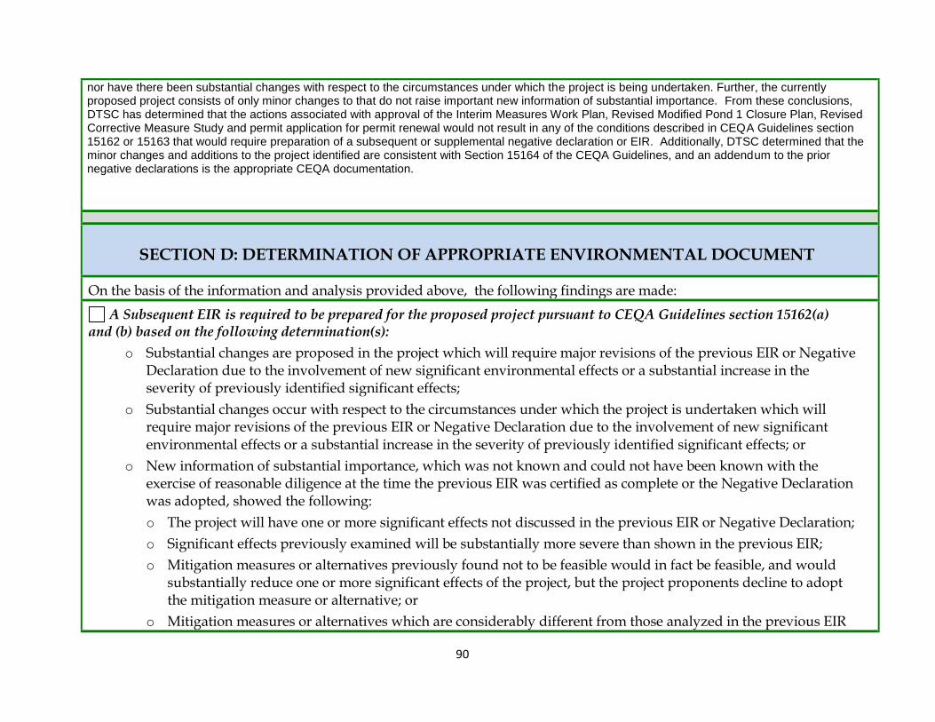
90
nor have there been substantial changes with respect to the circumstances under which the project is being undertaken. Further, the currently proposed project consists of only minor changes to that do not raise important new information of substantial importance. From these conclusions, DTSC has determined that the actions associated with approval of the Interim Measures Work Plan, Revised Modified Pond 1 Closure Plan, Revised Corrective Measure Study and permit application for permit renewal would not result in any of the conditions described in CEQA Guidelines section 15162 or 15163 that would require preparation of a subsequent or supplemental negative declaration or EIR. Additionally, DTSC determined that the minor changes and additions to the project identified are consistent with Section 15164 of the CEQA Guidelines, and an addendum to the prior negative declarations is the appropriate CEQA documentation.
SECTION D: DETERMINATION OF APPROPRIATE ENVIRONMENTAL DOCUMENT
On the basis of the information and analysis provided above, the following findings are made:
A Subsequent EIR is required to be prepared for the proposed project pursuant to CEQA Guidelines section 15162(a) and (b) based on the following determination(s):
o Substantial changes are proposed in the project which will require major revisions of the previous EIR or Negative Declaration due to the involvement of new significant environmental effects or a substantial increase in the severity of previously identified significant effects;
o Substantial changes occur with respect to the circumstances under which the project is undertaken which will require major revisions of the previous EIR or Negative Declaration due to the involvement of new significant environmental effects or a substantial increase in the severity of previously identified significant effects; or
o New information of substantial importance, which was not known and could not have been known with the exercise of reasonable diligence at the time the previous EIR was certified as complete or the Negative Declaration was adopted, showed the following:
o The project will have one or more significant effects not discussed in the previous EIR or Negative Declaration;
o Significant effects previously examined will be substantially more severe than shown in the previous EIR;
o Mitigation measures or alternatives previously found not to be feasible would in fact be feasible, and would substantially reduce one or more significant effects of the project, but the project proponents decline to adopt the mitigation measure or alternative; or
o Mitigation measures or alternatives which are considerably different from those analyzed in the previous EIR

91
would substantially reduce one or more significant effects on the environment, but the project proponents decline to adopt the mitigation measure or alternative.
o Changes to the project or its circumstances occurred or new information became available after adoption of the Negative Declaration, and a Subsequent EIR is required under CEQA Guidelines section 15162 (a).
A Supplement to an EIR is required to be prepared for the proposed project pursuant to CEQA Guidelines section 15163(a)(1) and (2) based on the following determination(s):
o One or more of the conditions described in Section 15162 required the preparation of a subsequent EIR, and
o Only minor additions or changes would be necessary to make the previous EIR adequately apply to the project in the changed situation.
An Addendum to a previously certified Environmental Impact Report is required to be prepared for the proposed project pursuant to CEQA Guidelines section 15164(a) based on the following determination(s):
o Some changes or additions are necessary but none of the conditions described in CEQA Guidelines section 15162 calling for the preparation of a subsequent EIR have occurred.
An Addendum to an adopted Negative Declaration is required to be prepared for the proposed project pursuant to CEQA Guidelines section 15164(b) based on the following determination(s):
o Only minor technical changes or additions are necessary; or
o None of the conditions described in CEQA Guidelines section 15162 calling for the preparation of a subsequent EIR or Negative Declaration have occurred.
No additional documentation is required to be prepared for the proposed project pursuant to CEQA Guidelines section 15162(b).