century 125 i.e e4 - kymco · 2019. 10. 30. · century 125 i.e. e nglish this manual for service...
TRANSCRIPT

CENTURY 125 i.e E4
Eng ine Workshop Manua l
EngineWorkshop Manual
Century 125i.e.
EN
GLIS
HThe descriptions and images in this publication are given for illustrative purposes only and are not binding. While the basic characteristics as described and illustrated in this booklet remain unchanged, Rieju S.A. reserves the right, at any time and without being required to update this publication beforehand, to make any changes to components, parts or accessories, which it considers necessary to improve the product
or which are required for manufacturing or construction reasons.Not all versions/models shown in this publication are available in all countries. The availability of each
model should be checked at the official RIEJU sales network.© Copyright 2014 - Rieju S.A. All rights reserved. Reproduction of this publication in whole or in part is
prohibited.Rieju S.A. C/ Borrassà 41 E-17600 Figueres GIRONA-SPAIN
www.riejumoto.com
ENGINE WORKSHOP MANUAL Century 125 i.e.
EN
GLIS
H
This manual for service stations was made by Rieju S.A. to be used by the workshops of dealers and sub-agencies RIEJU. It is assumed that users of this publication for the maintenance and repair of Rieju vehicles has a basic knowledge of the principles of mechanics and technique procedures of vehicle repair. Any significant changes to vehicle characteristics or specific repair operations will be communicated by updates to this manual.
N.B. Provides key information to make the procedure easier to understand and carry out.
CAUTION Refers to specific procedures to carry out for preventing damages to the vehicle.
WARNING Refers to specific procedures to carry out to prevent injuries to the repairer.
Personal safety Failure to completely observe these instructions will result in serious risk of personalinjury.
Safeguarding the environment Sections marked with this symbol indicate the correct use of the vehicleto prevent damaging the environment.
Vehicle intactness The incomplete or non-observance of these regulations leads to the risk of seriousdamage to the vehicle and sometimes even the invalidity of the guarantee.
6
8
14
19
21
23
32
36
43
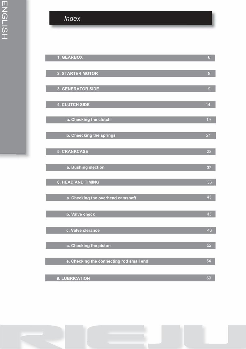
1. GEARBOX
2. STARTER MOTOR
3. GENERATOR SIDE
4. CLUTCH SIDE
a. Checking the clutch
b. Cheecking the springs
5. CRANKCASE
a. Bushing slection
6. HEAD AND TIMING
a. Checking the overhead camshaft
6.
9
EN
GLIS
H
Index
43
46
52
54
599. LUBRICATION
c. Valve cleranceb. Valve check
d. e. Checking the connecting rod small end
b. Valve checkc. Valve clerance
b. Valve checkc. Checking the piston

Engine
EN
GLIS
H
5

Engine
6
EN
GLIS
H
Gearbox
Gearbox shafts
Disassembling the gearbox
• Open the crankcase halves.
• Remove the gaskets from the crank-
case.
• Take out both fork rods and the trans-
mission forks (1) (2).
• Take out the desmodromic control (3).
• Take out the secondary axle (4).
• Take out the primary axle (5).
See also
Crankcase opening
Checking the primary shaft
COUPLING CLASSES
The gears of the primary drive are classified according to the coupling with the gear of the clutch housing
and with the gear of the balancing countershaft and follow the logic shown in the tables listed below:
COUPLING CLASSES CLUTCH HOUSING - FIRST GEAR SHAFTCoupling classes on Crankcase Clutch housing gear Transmission gear
X X XY Y Y
COUPLING CLASSES FIRST GEAR SHAFT - BALANCING COUNTERSHAFTCoupling classes on Crankcase Transmission gear Balancing countershaft gear
S S ST T T
NOTE

EN
GLIS
H
Engine
7
THE CLASS AS WELL AS BEING REPRODUCED ON TWO COUPLING ELEMENTS IS ALSOSHOWN ON THE TWO CRANKCASE HALVES OF THE CRANKCASE.NOTE
CRANKCASE SPARE PARTS ARE ALWAYS CLASS X.
Checking the desmodromic drum
• Check the contact zone on fork (1) and the driving pin (2) of the forks for wear.
• Check the desmodromic drum (4) grooves (3) for wear.
• Make sure that both ball bearings rotate freely and check if there are signs of corrosion.
• Check the eccentricity of the transmis-
sion shafts.
• Check the condition of the two springs
(5) and (6) of the selector (7).
• Check the condition of the gears, re-
place them if they are blue, if they have
cracks or are worn.
Assembling the gearbox
• Place the specific tool on the secon-
dary shaft to avoid damaging the oil
seal.
• Heat up the engine crankcase.
• Apply LOCTITE Anti-Seize on the
bearing seats present on the crank-
case.
• Fit the bearings in their seats.
• Insert the gears unit (5).
• Apply oil for gears on the grooves of the desmodromic drum.
Engine
8
EN
GLIS
H
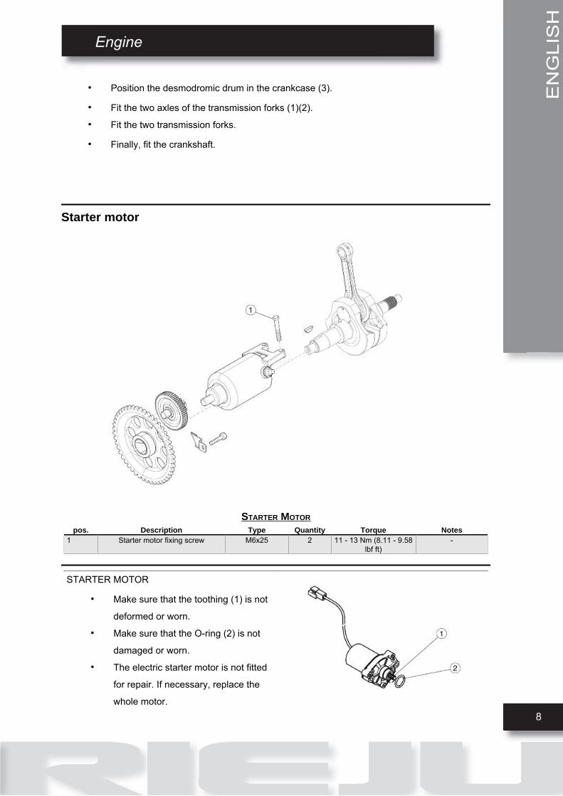
• Position the desmodromic drum in the crankcase (3).
• Fit the two axles of the transmission forks (1)(2).
• Fit the two transmission forks.
• Finally, fit the crankshaft.
Starter motor
STARTER MOTORpos. Description Type Quantity Torque Notes
1 Starter motor fixing screw M6x25 2 11 - 13 Nm (8.11 - 9.58lbf ft)
-
STARTER MOTOR
• Make sure that the toothing (1) is not
deformed or worn.
• Make sure that the O-ring (2) is not
damaged or worn.
• The electric starter motor is not fitted
for repair. If necessary, replace the
whole motor.

EN
GLIS
H
Engine
9
Removing the starter motor
• Undo and remove the two fixing screws
(1).
• Remove the starter motor (2).NOTETHE STARTER MOTOR CAN ALSO BE REMOVED IF THEENGINE IS FITTED TO THE VEHICLE.
Installing the starter motor
• Place the electric starter motor.
• Apply LOCTITE 221.
• Tighten the starter motor fixing screws.
Generator side
FLYWHEEL COVERpos. Description Type Quantity Torque Notes
1 Flywheel cover fastener screw M6 10 11 - 13 Nm (8.11 - 9.58lbf ft)
-

Engine
10
EN
GLIS
H
pos. Description Type Quantity Torque Notes2 Timing control cover M18 2 3.5 - 4.5 Nm (2.58 - 3.31
lbf ft)-
3 Oil dipstick M12x1.5 1 4 - 6 Nm (2.95 - 4.42 lbfft)
-
IGNITION UNITpos. Description Type Quantity Torque Notes
1 Flywheel rotor fixing screw M14x1.5 1 83 - 90 Nm (61.21 -66.38 lb ft)
-
Removing the flywheel cover
• Unscrew and remove the two adjust-
ment plugs (1).
• Unscrew and remove the engine oil
pre-filter plug (2).
• Remove the engine oil pre-filter.
• Undo and remove the ten screws fixing
the flywheel cover.
• Remove the flywheel cover.
EN
GLIS
H
Engine
11
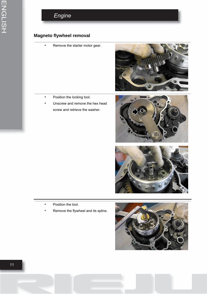
Magneto flywheel removal
• Remove the starter motor gear.
• Position the locking tool.
• Unscrew and remove the hex head
screw and retrieve the washer.
• Position the tool.
• Remove the flywheel and its spline.

Engine
12
EN
GLIS
H
• Remove the oil filter.

EN
GLIS
H
Engine
13
Freewheel removal
• Undo and remove the screw from the
lock.
• Remove the freewheel.
Installing the flywheel
For refitting follow the operations described previously in reverse order.
See also
Magneto flywheel removal
Motor
14
EN
GLIS
H
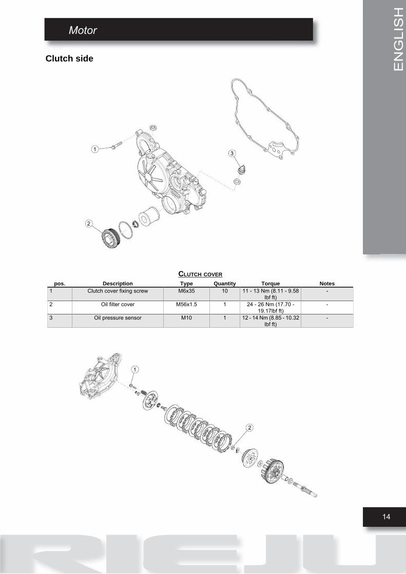
Clutch side
CLUTCH COVERpos. Description Type Quantity Torque Notes
1 Clutch cover fixing screw M6x35 10 11 - 13 Nm (8.11 - 9.58lbf ft)
-
2 Oil filter cover M56x1.5 1 24 - 26 Nm (17.70 -19.17lbf ft)
-
3 Oil pressure sensor M10 1 12 - 14 Nm (8.85 - 10.32lbf ft)
-

EN
GLIS
H
Engine
15
CLUTCHpos. Description Type Quantity Torque Notes
1 Clutch spring screw M5 5 3.5 - 4.5 Nm (2.58 - 3.31lbf ft)
-
2 Clutch housing retainer nut M12 1 35 - 45 Nm (25.81 -33.19 lbf ft)
-
Removing the clutch cover
• Unscrew and remove the three water
pump cover screws.
• Remove the water pump cover.
• Unscrew and remove the rotor fixing
screw.
• Remove the rotor.

Engine
16
EN
GLIS
H
• Unscrew and remove the oil filter plug.
• Remove the spring and oil filter.

EN
GLIS
H
Engine
17
• Unscrew and remove the ten clutch
cover screws.
• Remove the clutch cover and the gas-
ket.
• Collect the dowel pins.WARNING
REPLACE THE GASKET DURING REFITTING.
• Remove the lubrication circuit by-pass
spring.
Disassembling the clutch
• Unscrew and remove the six screws by
loosening them 1/4 of a turn at a time;
operate in stages and diagonally, and
retrieve the washers and the clutch
springs.
Engine
18
EN
GLIS
H
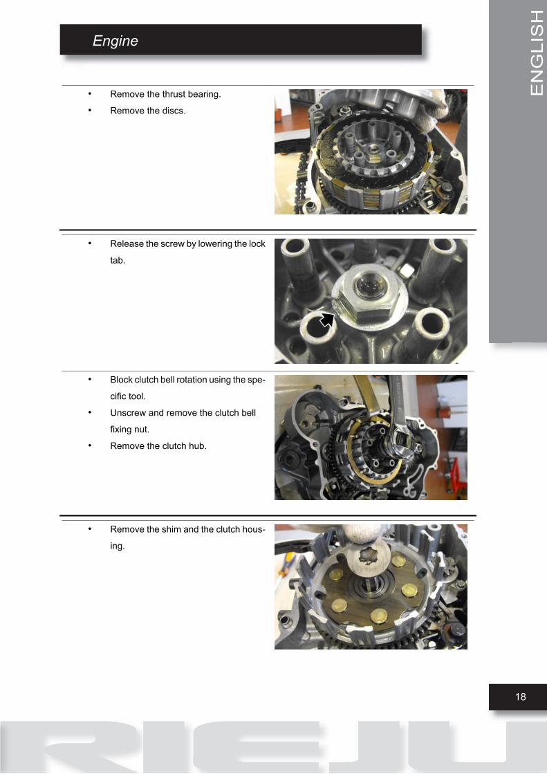
• Remove the thrust bearing.
• Remove the discs.
• Release the screw by lowering the lock
tab.
• Block clutch bell rotation using the spe-
cific tool.
• Unscrew and remove the clutch bell
fixing nut.
• Remove the clutch hub.
• Remove the shim and the clutch hous-
ing.

ENGLISH
Engine
19
• Remove the shim.
Checking the clutch plates
CharacteristicDriving plates thickness2.85 - 2.95 mm (0.112 - 0.116 in)
Number of driving plates5
Driven plates thickness1.46 - 1.53 mm (0.057 - 0.06 in)
Number of driven plates4
Checking the clutch housing
COUPLING CLASSES
The gears that are coupled to each other: clutch housing, first gear shaft and balancing countershaft,
indicate the coupling classes; in this regard, see section "Checking the primary shaft" within the topic
"Gearshift".
Engine
20
ENGLISH
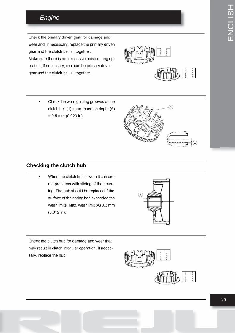
Check the primary driven gear for damage and
wear and, if necessary, replace the primary driven
gear and the clutch bell all together.
Make sure there is not excessive noise during op-
eration; if necessary, replace the primary drive
gear and the clutch bell all together.
• Check the worn guiding grooves of the
clutch bell (1); max. insertion depth (A)
= 0.5 mm (0.020 in).
Checking the clutch hub
• When the clutch hub is worn it can cre-
ate problems with sliding of the hous-
ing. The hub should be replaced if the
surface of the spring has exceeded the
wear limits. Max. wear limit (A) 0.3 mm
(0.012 in).
Check the clutch hub for damage and wear that
may result in clutch irregular operation. If neces-
sary, replace the hub.
ENGLISH
Engine
21
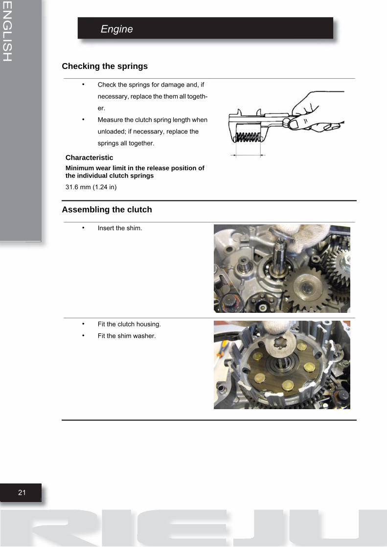
Checking the springs
• Check the springs for damage and, if
necessary, replace the them all togeth-
er.
• Measure the clutch spring length when
unloaded; if necessary, replace the
springs all together.
CharacteristicMinimum wear limit in the release position ofthe individual clutch springs31.6 mm (1.24 in)
Assembling the clutch
• Insert the shim.
• Fit the clutch housing.
• Fit the shim washer.

Engine
22
ENGLISH
• Insert the clutch hub.
• Screw in the retainer nut locking the
rotation of the clutch housing with the
specific tool.
• Lift one side of the lock tab.
• Insert the disc covered with the friction material into the bell.
• Continue inserting, alternating a metal
disc with one with friction material, fin-
ishing with a friction material disc with
a black tooth.
• Place the thrust plate.
• Fit the clutch springs.
• Fit the screw washers.
• Tighten the six screws operating in stages and diagonally.

ENGLISH
Engine
23
• Insert a new gasket.
• Position the dowel pins and the cover.
• Position the clutch cable support.
• Screw in the ten screws, tightening di-
agonally and in stages.
• Refit the water pump.
• Refit the oil filter.
• Add engine oil up to the correct level.WARNING
TO FACILITATE INSERTION OF THE COVER, ROTATE WA-TER PUMP THE ROTOR UNTIL THE GEARS ENGAGE.
Crankcase
ENGINE CRANKCASEpos. Description Type Quantity Torque Notes
1 Crankcase halves union M6 12 11 - 13 Nm (8.11 - 9.58lbf ft)
-

Engine
24
ENGLISH
CRANKSHAFTpos. Description Type Quantity Torque Notes
1 Countershaft gear retainer nut M10 1 35 - 45 Nm (25.81 -33.19 lbf ft)
-
Balancing countershaft removal
• Before taking out the balancing coun-
tershaft the clutch cover and flywheel
cover must be removed.
• Lock the countershaft with the specific
tool.
• Unscrew and remove the nut and col-
lect the washer
See also
ENGLISH
Engine
25
Removing the clutch coverRemoving the flywheel cover
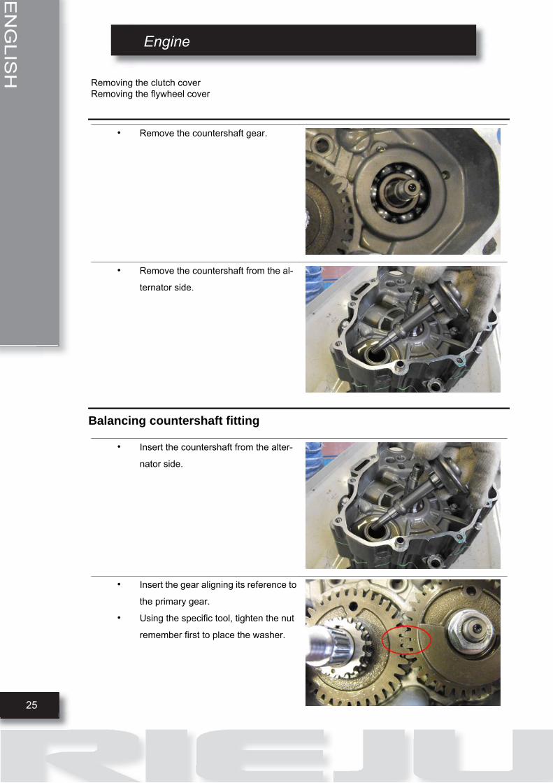
• Remove the countershaft gear.
• Remove the countershaft from the al-
ternator side.
Balancing countershaft fitting
• Insert the countershaft from the alter-
nator side.
• Insert the gear aligning its reference to
the primary gear.
• Using the specific tool, tighten the nut
remember first to place the washer.
Engine
26
ENGLISH
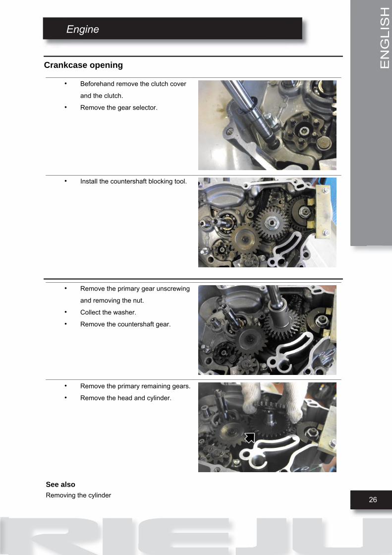
Crankcase opening
• Beforehand remove the clutch cover
and the clutch.
• Remove the gear selector.
• Install the countershaft blocking tool.
• Remove the primary gear unscrewing
and removing the nut.
• Collect the washer.
• Remove the countershaft gear.
• Remove the primary remaining gears.
• Remove the head and cylinder.
See alsoRemoving the cylinder
ENGLISH
Engine
27
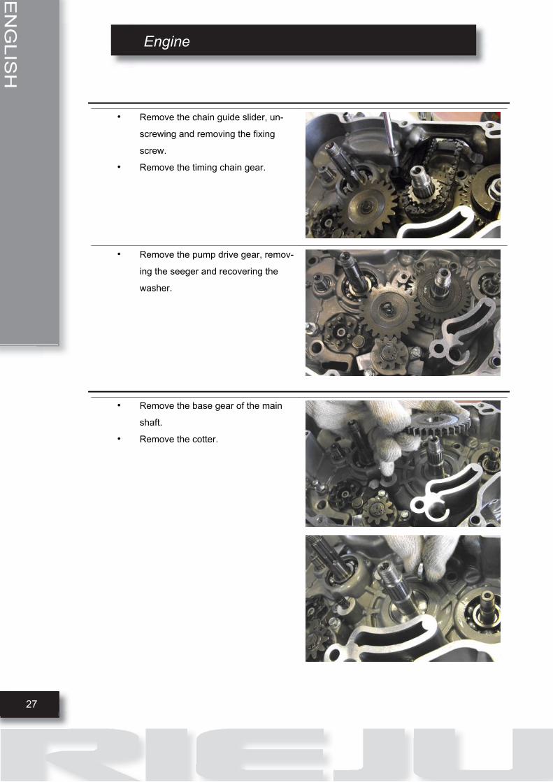
• Remove the chain guide slider, un-
screwing and removing the fixing
screw.
• Remove the timing chain gear.
• Remove the pump drive gear, remov-
ing the seeger and recovering the
washer.
• Remove the base gear of the main
shaft.
• Remove the cotter.
Engine
28
ENGLISH
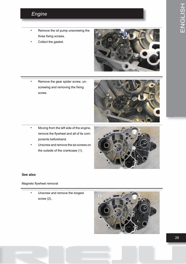
• Remove the oil pump unscrewing the
three fixing screws.
• Collect the gasket.
• Remove the gear spider screw, un-
screwing and removing the fixing
screw.
• Moving from the left side of the engine,
remove the flywheel and all of its com-
ponents beforehand.
• Unscrew and remove the six screws on
the outside of the crankcase (1).
See also
Magneto flywheel removal
• Unscrew and remove the longest
screw (2).
ENGLISH
Engine
29
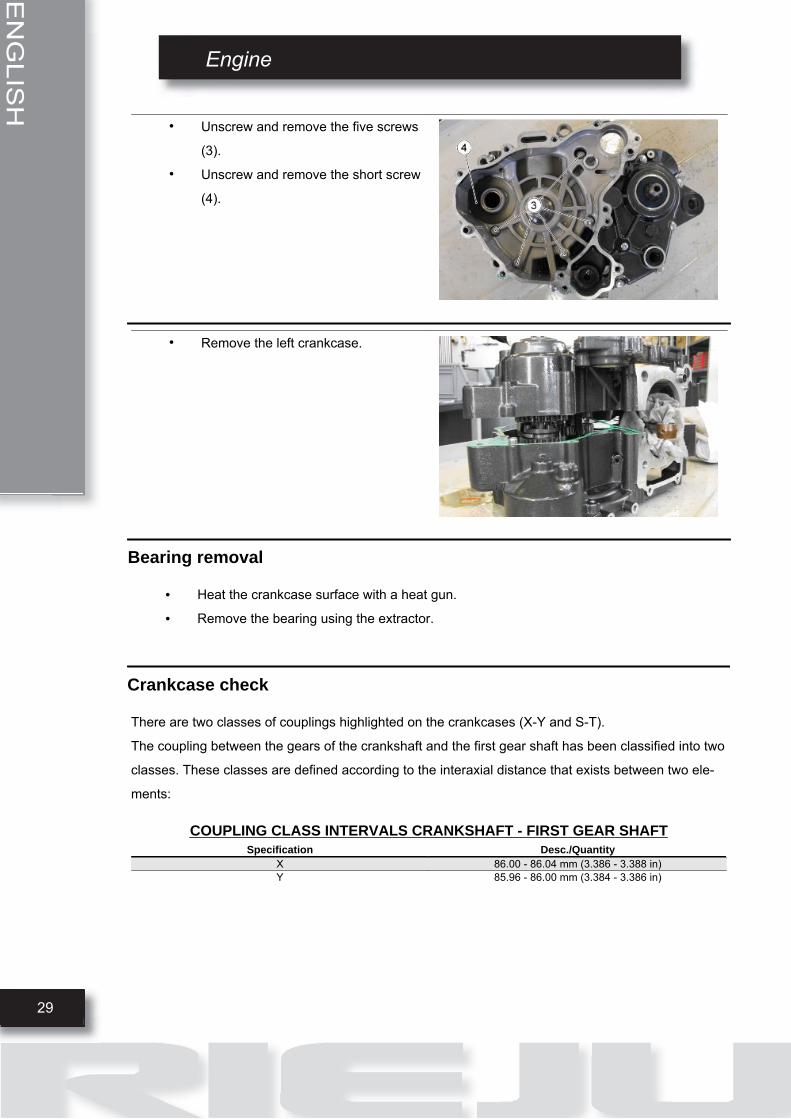
• Unscrew and remove the five screws
(3).
• Unscrew and remove the short screw
(4).
• Remove the left crankcase.
Bearing removal
• Heat the crankcase surface with a heat gun.
• Remove the bearing using the extractor.
Crankcase check
There are two classes of couplings highlighted on the crankcases (X-Y and S-T).
The coupling between the gears of the crankshaft and the first gear shaft has been classified into two
classes. These classes are defined according to the interaxial distance that exists between two ele-
ments:
COUPLING CLASS INTERVALS CRANKSHAFT - FIRST GEAR SHAFTSpecification Desc./Quantity
X 86.00 - 86.04 mm (3.386 - 3.388 in)Y 85.96 - 86.00 mm (3.384 - 3.386 in)
30
ENGLISH
Engine
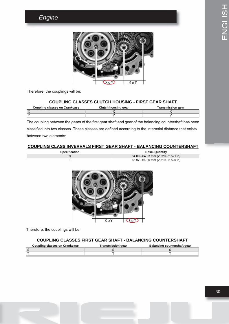
Therefore, the couplings will be:
COUPLING CLASSES CLUTCH HOUSING - FIRST GEAR SHAFTCoupling classes on Crankcase Clutch housing gear Transmission gear
X X XY Y Y
The coupling between the gears of the first gear shaft and gear of the balancing countershaft has been
classified into two classes. These classes are defined according to the interaxial distance that exists
between two elements:
COUPLING CLASS INVERVALS FIRST GEAR SHAFT - BALANCING COUNTERSHAFTSpecification Desc./Quantity
S 64.00 - 64.03 mm (2.520 - 2.521 in)T 63.97 - 64.00 mm (2.519 - 2.520 in)
Therefore, the couplings will be:
COUPLING CLASSES FIRST GEAR SHAFT - BALANCING COUNTERSHAFTCoupling classes on Crankcase Transmission gear Balancing countershaft gear
S S ST T T

ENGLISH
Engine
31
The classes of the transmission elements are also
listed on the two crankcase halves.
NOTE
CRANKCASE SPARE PARTS ARE ALWAYS CLASS X.
Crankshaft check
• Before checking the crankcase halves, thoroughly clean all the surfaces and the oil pipes.
• For the crankcase half on the transmission side, take particular care when handling the
housing and hoses for the oil pump, the duct with the by-pass valve and the main bushings.
• As already described in the lubrication chapter, it is especially important that the by-pass
valve housing shows no wear that may impair the proper sealing of the lubrication pressure
adjustment ball.
• Check that the surfaces are free from dents or deformations, with special attention to both
the crankcase coupling and the cylinder-crankcase surfaces.
• Defects in the crankcase coupling gasket or the surfaces indicated in the figure can cause
a drop in the oil pressure and affect the lubrication pressure for the main bushings and the
connecting rod.• Check that the surfaces that limit crankshaft axial clearance show no signs of wear. To
measure and check sizes follow the procedure described previously for checking crankshaft
axial clearance and dimensions.
Balancing countershaft check
COUPLING CLASSES
The gears that are coupled to each other: clutch housing, first gear shaft and balancing countershaft,
indicate the coupling classes; in this regard, see section "Checking the primary shaft" within the topic
"Gearshift".

Engine
32
ENGLISH
Bushing selection
BUSHING SEAT DIAMETER ON CRANKCASESpecification Desc./Quantity
Class 1 MIN 36.500 mm (1.4370 in)MAX 36.508 mm (1.4373 in)
Class 2 MIN 36.508 mm (1.4373 in)MAX 36.516 mm (1.4376 in)
CRANKSHAFT DIAMETERSpecification Desc./Quantity
Class 1 MIN 32.480 mm (1.2787 in)MAX 32.485 mm (1.2789 in)
Class 2 MIN 32.485 mm (1.2789 in)MAX 32.490 mm (1.2791 in)
BUSHING THICKNESSSpecification Desc./Quantity
Red MIN 2.005 mm (0.0789 in)MAX 2.010 mm (0.0791 in)
Blue MIN 2.010 mm (0.0791 in)MAX 2.015 mm (0.0793 in)
CRANKSHAFT COUPLING/BUSHING SEAT DIAMETERSpecification Desc./Quantity
Crankshaft type 2 Type 1 crankcase diameter RED + REDType 2 crankcase diameter RED + BLUE
Crankshaft type 1 Type 1 crankcase diameter RED + BLUEType 2 crankcase diameter BLUE + BLUE
Bearing fitting
• Heat up the crankcase using the thermal gun.
• Fit the bearing in the seat with the aid of the tool.
NOTE: insertion of the roller bearing cages in line with the crankcase is recommended from the
inside to the outside.
Crankcase closing
• After fitting the transmission, fit a new
gasket.
• Close the two crankcases using the
dowel pins.

ENGLISH
Engine
33
• Position and screw the short screw (4).
• Position and screw the five screws (3).
See also Assembling the gearbox
• Position and screw the long screw (2).
• Moving from the left side of the crank-
case, position and screw the six
screws (1).
• Fit the countershaft.
• Position the selection spider screw.
• Position and screw the screw.
See alsoBalancing countershaft fitting

Engine
34
ENGLISH
• Fit a new oil pump gasket.
• Fit the oil pump, screwing the three
screws.
• Insert the countershaft gear and posi-
tion the washer.
• Use the specific tool to tighten the nut.
• Apply the cotter to the main shaft.
• Position the base gear of the primary,
aligning the two references.

ENGLISH
Engine
35
• Insert the pump drive gear.
• Insert the washer and apply the fixing
seeger.
• Insert the timing chain gear, paying at-
tention to the direction. The engraving
must face upward.
• Fit the timing chain.
• Position the chain guide slider.
• Position and screw the fixing screw.
• Fit the rest of the primary gears.
• Tighten the fixing nut.
• Remove the countershaft locking tool.
Engine
36
ENGLISH
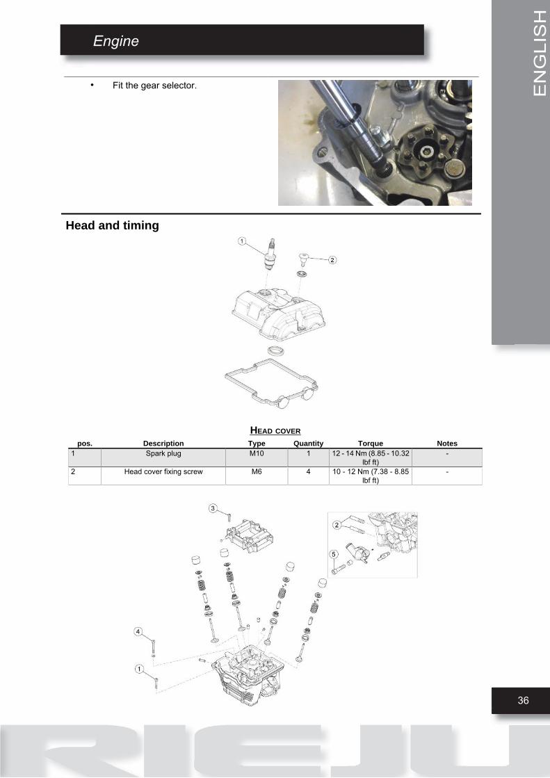
• Fit the gear selector.
Head and timing
HEAD COVERpos. Description Type Quantity Torque Notes
1 Spark plug M10 1 12 - 14 Nm (8.85 - 10.32lbf ft)
-
2 Head cover fixing screw M6 4 10 - 12 Nm (7.38 - 8.85lbf ft)
-

ENGLISH
Engine
37
HEAD - VALVESpos. Description Type Quantity Torque Notes
1 Head fastener screw, chain side M6x130 2 11 Nm (8.11 lbf ft) -2 Exhaust side fixing stud bolt M8x40 2 12 Nm (8.85 lbf ft) -3 Camshaft support fixing screw M6x40 8 10 Nm (7.38 lbf ft) -4 Head fixing screw M8x166 4 25 Nm + 90° (18.44 lbf ft
+ 90°-
5 Thermostat cover fixing screw M6x20 2 10 Nm (7.38 lbf ft) -
TIMING SYSTEMpos. Description Type Quantity Torque Notes
1 Chain tensioner slider fulcrum fixingscrew
M6x16 1 10 Nm (7.38 lbf ft) Loctite 243
2 Transmission timing gear fixingscrew
M8x40 1 27 Nm (19.91 lbf ft) Loctite 243
Removing the head cover
• Remove the adjuster screw covers (1).

Engine
38
ENGLISH
• Unscrew and remove the four cylinder
head screws (2).
• Remove the cylinder head (3).
• Remove the gasket (4).
• Remove the spark plug.

ENGLISH
Engine
39
Removing the timing control
• Turn the crankshaft from the hole on
the cover (1)
• Take the piston to TDC.
• The sign (2) must be aligned with the
sign (3).
• Insert the specific pins (4) on the valves
cam tower.
• Remove the starter motor beforehand.
• Loosen and remove the tensioner
screw (5).
• Remove the spring.
• Unscrew and remove the two screws
(6)6) and remove the entire tensio
control.
See alsoRemoving the starter motor

Engine
40
ENGLISH
• Lock the timing gear using the tool.
• Unscrew and remove the gear.
• Repeat the operation with the other
gear.
Cylinder head
Removing the overhead camshaft
)
•
11
• Unscrew and remove the six screws
(1)1)) a
Remove the cylinder head (3).
ENGLISH
Engine
41
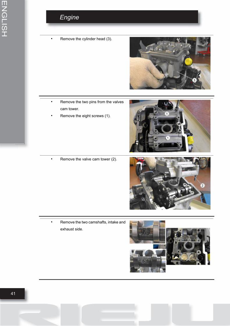
• Remove the cylinder head (3).
• Remove the two pins from the valves
cam tower.
• Remove the eight screws (1).
• Remove the valve cam tower (2).
• Remove the two camshafts, intake and
exhaust side.

Engine
42
ENGLISH
Removing the valves
• Remove the head.
• Place the head on supporting surface.
• Number the valves and their bucket
tappets in order to position them cor-
rectly upon refitting.
• Remove the valve bucket tappets.
• Compress the valve spring using the
tool.
• Remove both cotter pins.
ENGLISH
Engine
43
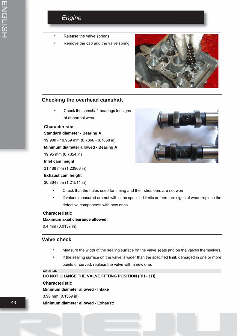
• Release the valve springs.
• Remove the cap and the valve spring.
Checking the overhead camshaft
• Check the camshaft bearings for signs
of abnormal wear.
CharacteristicStandard diameter - Bearing A19.980 - 19.959 mm (0.7866 - 0.7858 in)
Minimum diameter allowed - Bearing A19.95 mm (0.7854 in)
Inlet cam height31.488 mm (1.23968 in)
Exhaust cam height30.864 mm (1.21511 in)
• Check that the holes used for timing and their shoulders are not worn.
• If values measured are not within the specified limits or there are signs of wear, replace the
defective components with new ones.
CharacteristicMaximum axial clearance allowed:0.4 mm (0.0157 in)
Valve check
• Measure the width of the sealing surface on the valve seats and on the valves themselves.
• If the sealing surface on the valve is wider than the specified limit, damaged in one or more
points or curved, replace the valve with a new one.CAUTIONDO NOT CHANGE THE VALVE FITTING POSITION (RH - LH).
CharacteristicMinimum diameter allowed - Intake3.96 mm (0.1559 in)
Minimum diameter allowed - Exhaust:

Engine
44
ENGLISH
3.95 mm (0.1555 in)
Standard clearance - Intake:
0.015/0.042 mm (0.00059/ 0.0016 in)
Standard clearance - Exhaust:
0.025/0.052 mm (0.00098/ 0.00204 in)
Maximum clearance admitted - Intake:
0.060 mm (0.0023 in)
Maximum clearance admitted - Exhaust:
0.070 mm (0.0027 in)
• Remove the head cover.
• Bring the engine to reach the top dead
centre and lock it at that position using
the tool (4).
ENGLISH
Engine
45
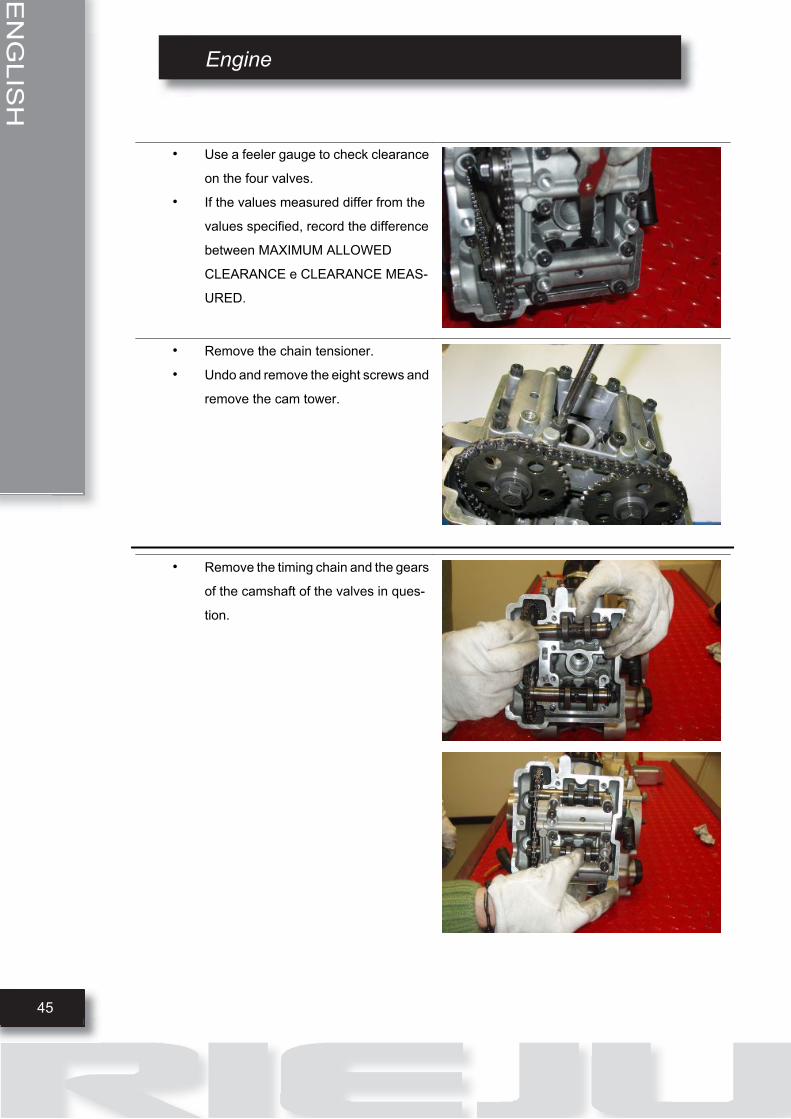
• Use a feeler gauge to check clearance
on the four valves.
• If the values measured differ from the
values specified, record the difference
between MAXIMUM ALLOWED
CLEARANCE e CLEARANCE MEAS-
URED.
• Remove the chain tensioner.
• Undo and remove the eight screws and
remove the cam tower.
• Remove the timing chain and the gears
of the camshaft of the valves in ques-
tion.
Engine
46
ENGLISH
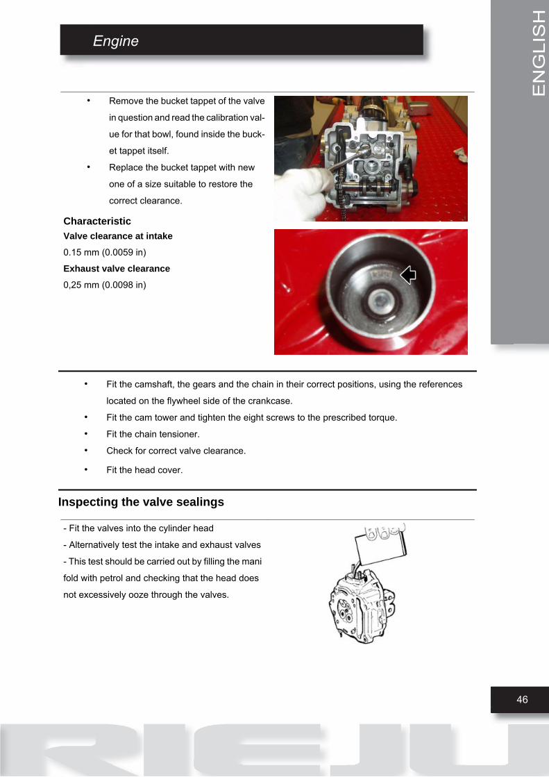
• Remove the bucket tappet of the valve
in question and read the calibration val-
ue for that bowl, found inside the buck-
et tappet itself.
• Replace the bucket tappet with new
one of a size suitable to restore the
correct clearance.
CharacteristicValve clearance at intake0.15 mm (0.0059 in)
Exhaust valve clearance0,25 mm (0.0098 in)
• Fit the camshaft, the gears and the chain in their correct positions, using the references
located on the flywheel side of the crankcase.
• Fit the cam tower and tighten the eight screws to the prescribed torque.
• Fit the chain tensioner.
• Check for correct valve clearance.
• Fit the head cover.
Inspecting the valve sealings
- Fit the valves into the cylinder head
- Alternatively test the intake and exhaust valves
- This test should be carried out by filling the mani
fold with petrol and checking that the head does
not excessively ooze through the valves.
ENGLISH
Engine
47
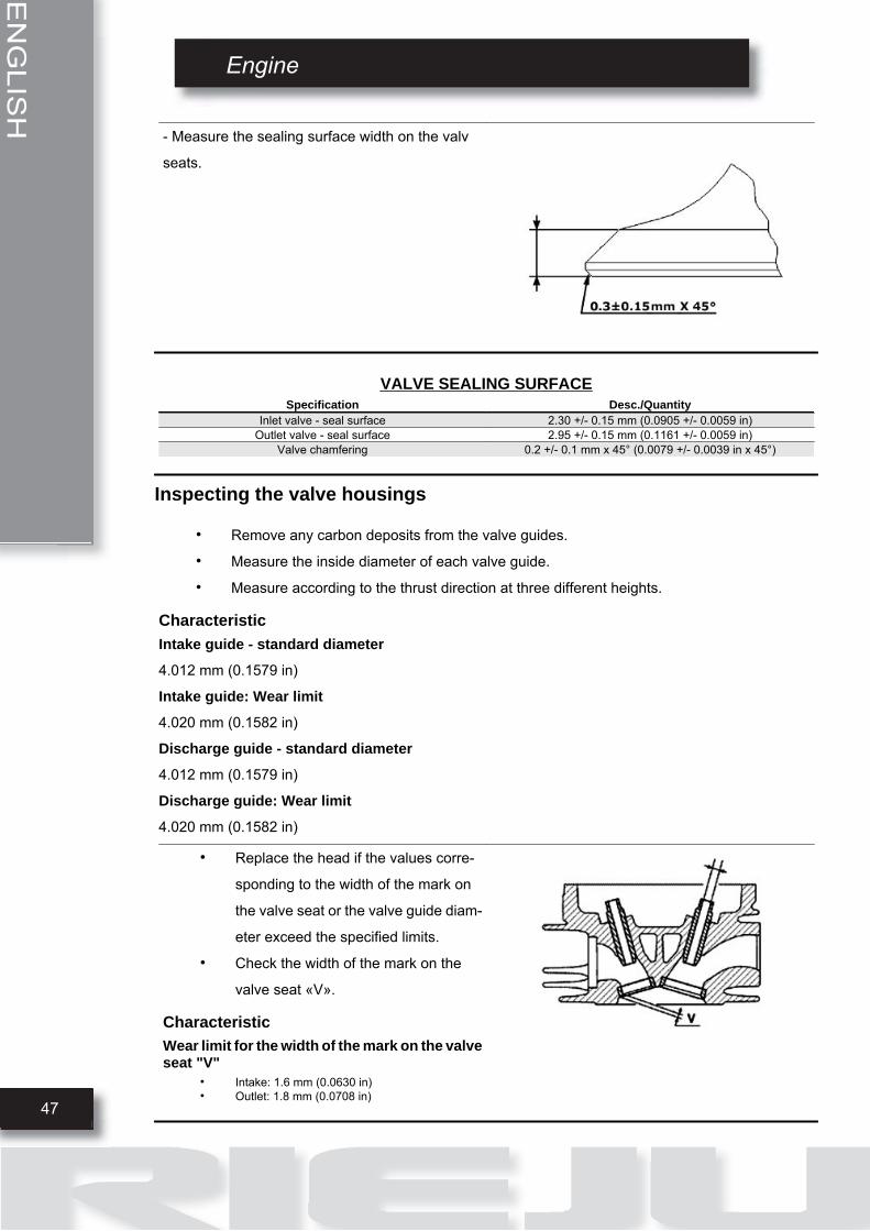
- Measure the sealing surface width on the valv
seats.
VALVE SEALING SURFACESpecification Desc./Quantity
Inlet valve - seal surface 2.30 +/- 0.15 mm (0.0905 +/- 0.0059 in)Outlet valve - seal surface 2.95 +/- 0.15 mm (0.1161 +/- 0.0059 in)
Valve chamfering 0.2 +/- 0.1 mm x 45° (0.0079 +/- 0.0039 in x 45°)
Inspecting the valve housings
• Remove any carbon deposits from the valve guides.
• Measure the inside diameter of each valve guide.
• Measure according to the thrust direction at three different heights.
CharacteristicIntake guide - standard diameter
4.012 mm (0.1579 in)
Intake guide: Wear limit
4.020 mm (0.1582 in)
Discharge guide - standard diameter
4.012 mm (0.1579 in)
Discharge guide: Wear limit
4.020 mm (0.1582 in)
• Replace the head if the values corre-
sponding to the width of the mark on
the valve seat or the valve guide diam-
eter exceed the specified limits.
• Check the width of the mark on the
valve seat «V».
CharacteristicWear limit for the width of the mark on the valveseat "V"
• Intake: 1.6 mm (0.0630 in)• Outlet: 1.8 mm (0.0708 in)

Engine
48
ENGLISH
Inspecting the springs and half-cones
• Check that the spring upper supporting
caps and the cotters show no signs of
abnormal wear.
• Check the unloaded spring length.
CharacteristicValve spring length:33.24 +/- 0.25 mm (1.3086 +/-0.0098 in)
Checking the cylinder head
• Using a trued bar, check that the head surface is not worn or distorted.
• Check that the camshaft bushings are not worn.
• Check that the head cover surface, the intake manifold and the exhaust manifold are not
worn.
Installing the valves
• Lubricate the valve guides with engine oil.
• Position the two oil seals on the cylinder head.
- Fit the valves, the springs and the caps. Usin
the specific tool, compress the springs and fit the
cotters in their seats.

ENGLISH
Engine
49
Checking the chain tensioner
CHAIN TENSIONER
• Remove the central screw with the
washer and the tensioner spring.
Check that the one-way mechanism is
not worn.
• Check the condition of the tensioner
spring.
• If signs of wear are found, replace the
whole assembly.
Checking the chain• Check that the guide slider and the ten-
sioner pad are not excessively worn.
• Check that the chain assembly, the
camshaft driving pulleys and the
sprocket wheel are not worn.
• Replace the parts if signs of wear are
found.
Cylinder-piston assembly

Engine
50
ENGLISH
CYLINDER - PISTONpos. Description Type Quantity Torque Notes
1 Chain tensioner screw M8 1 6 Nm (4.43 lbf ft) -
Removing the cylinder
CYLINDER REMOVAL
• Remove the cylinder head gasket (1).
• Remove the guide slider (2).
• Remove the water sleeve clamp (3).
ENGLISH
Engine
51
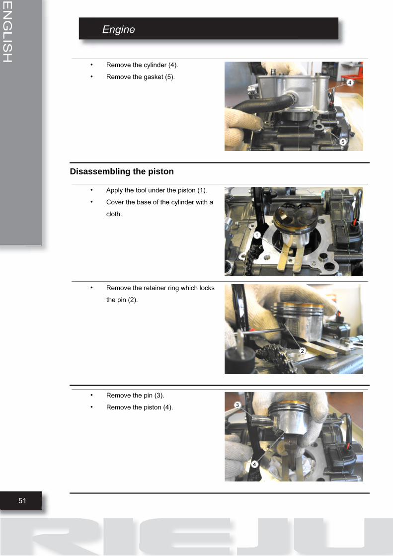
• Remove the cylinder (4).
• Remove the gasket (5).
Disassembling the piston
• Apply the tool under the piston (1).
• Cover the base of the cylinder with a
cloth.
• Remove the retainer ring which locks
the pin (2).
• Remove the pin (3).
• Remove the piston (4).
52
ENGLISH
Engine
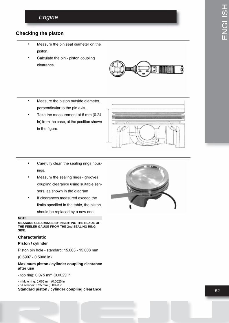
Checking the piston
• Measure the pin seat diameter on the
piston.
• Calculate the pin - piston coupling
clearance.
• Measure the piston outside diameter,
perpendicular to the pin axis.
• Take the measurement at 6 mm (0.24
in) from the base, at the position shown
in the figure.
• Carefully clean the sealing rings hous-
ings.
• Measure the sealing rings - grooves
coupling clearance using suitable sen-
sors, as shown in the diagram
• If clearances measured exceed the
limits specified in the table, the piston
should be replaced by a new one.NOTEMEASURE CLEARANCE BY INSERTING THE BLADE OFTHE FEELER GAUGE FROM THE 2nd SEALING RINGSIDE.
CharacteristicPiston / cylinderPiston pin hole - standard: 15.003 - 15.008 mm
(0.5907 - 0.5908 in)
Maximum piston / cylinder coupling clearanceafter use- top ring: 0.075 mm (0.0029 in- middle ring: 0.065 mm (0.0025 in- oil scraper: 0.25 mm (0.0098 inStandard piston / cylinder coupling clearance
ENGLISH
53
Engine
- top ring: +0.03 / 0.062 mm (0.0012 / 0.0024 in- middle ring: +0.02 / 0.052 mm (0.0008 / 0.0020 in- oil scraper: +0.01 / 0.19 mm (0.0004 / 0.007480 in
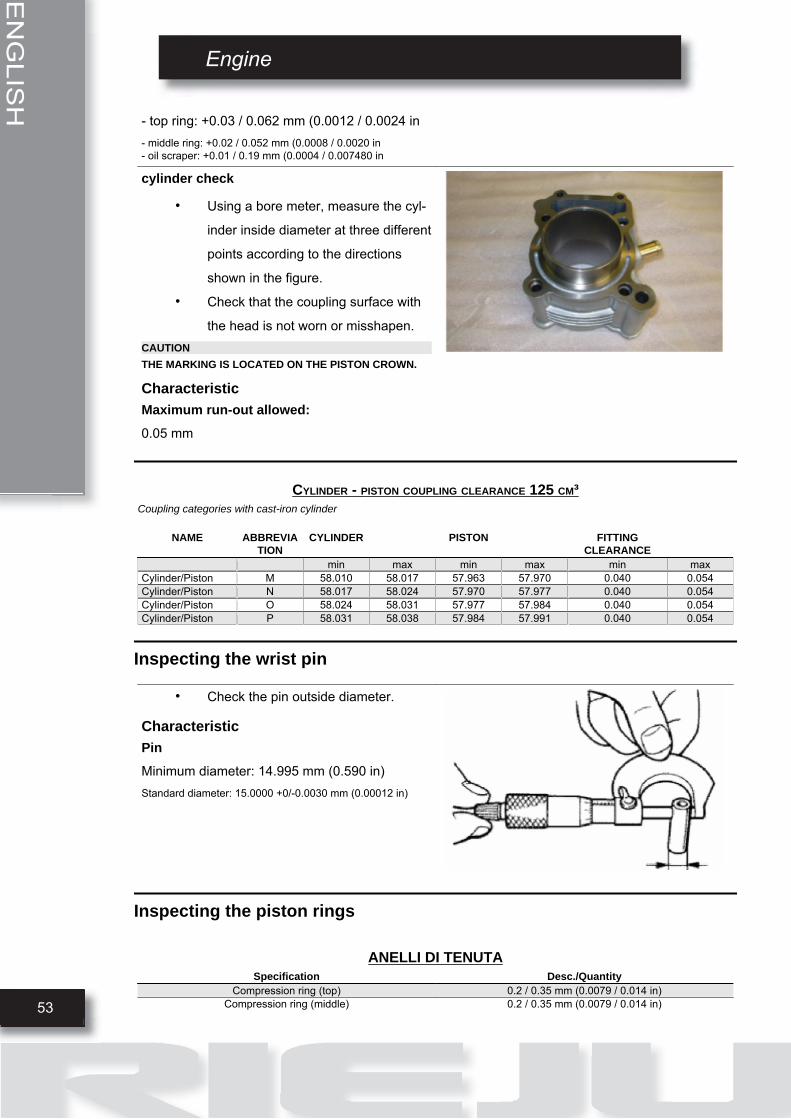
cylinder check
• Using a bore meter, measure the cyl-
inder inside diameter at three different
points according to the directions
shown in the figure.
• Check that the coupling surface with
the head is not worn or misshapen.CAUTIONTHE MARKING IS LOCATED ON THE PISTON CROWN.
CharacteristicMaximum run-out allowed:0.05 mm
CYLINDER - PISTON COUPLING CLEARANCE 125 CM³Coupling categories with cast-iron cylinder
NAME ABBREVIATION
CYLINDER PISTON FITTINGCLEARANCE
min max min max min maxCylinder/Piston M 58.010 58.017 57.963 57.970 0.040 0.054Cylinder/Piston N 58.017 58.024 57.970 57.977 0.040 0.054Cylinder/Piston O 58.024 58.031 57.977 57.984 0.040 0.054Cylinder/Piston P 58.031 58.038 57.984 57.991 0.040 0.054
Inspecting the wrist pin
• Check the pin outside diameter.
CharacteristicPinMinimum diameter: 14.995 mm (0.590 in)Standard diameter: 15.0000 +0/-0.0030 mm (0.00012 in)
Inspecting the piston rings
ANELLI DI TENUTASpecification Desc./Quantity
Compression ring (top) 0.2 / 0.35 mm (0.0079 / 0.014 in)Compression ring (middle) 0.2 / 0.35 mm (0.0079 / 0.014 in)

Engine
54
ENGLISH
Specification Desc./QuantityOil scraper ring 0.2 / 0.7 mm (0.0079 / 0.027 in)
Top ring maximum value 0.45 mm (0.18 in)Middle ring maximum value 0.45 mm (0.18 in)
Checking the connecting rod small end
• Measure the inside diameter of the
connecting rod small end using a spe-
cific micrometer.NOTEIF THE CONNECTING ROD SMALL END DIAMETER EX-CEEDS THE MAXIMUM DIAMETER ALLOWED, SHOWSSIGNS OF WEAR OR OVERHEATING, REPLACE THECRANKSHAFT AS DESCRIBED IN THE "CRANKCASEAND CRANKSHAFT" CHAPTER.
CharacteristicRod small endMaximum diameter: 15.023 mm (0.591 in)Standard diameter: 15.010 - 15.018 mm (0.5910 - 0.5912 in)
Fitting the piston
• Install piston and pin onto the connect-
ing rod, aligning the piston arrow the
arrow facing towards the exhaust.
• Fit the retainer ring.

ENGLISH
Engine
55
• Temporarily install the cylinder on the
piston, without the gasket of the cylin-
der's base.
• Fit a dial gauge on the specific tool.
• Take the piston to TDC.
• Position the dial gauge on one side of
the cylinder and fasten it in order to de-
tect the zero position correctly.
• Move the dial gauge diagonally and
measure the piston protrusion in rela-
tion to the reference surface.
• Calculate the necessary thickness of
the gasket, selecting it based on the
values shown in the table below.
Installing the cylinder
• Fit a new cylinder base gasket of the
chosen thickness.
• Refit the cylinder as indicated in the
figure using the specific clamp tighten-
er tool.NOTEBEFORE FITTING THE CYLINDER, CAREFULLY BLOW AIR INTO THE LUBRICATION DUCT AND LUBRICATE THE CYLINDER LINER.
Engine
56
ENGLISH
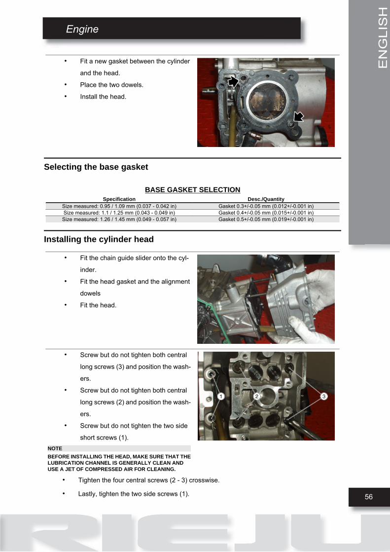
• Fit a new gasket between the cylinder
and the head.
• Place the two dowels.
• Install the head.
Selecting the base gasket
BASE GASKET SELECTIONSpecification Desc./Quantity
Size measured: 0.95 / 1.09 mm (0.037 - 0.042 in) Gasket 0.3+/-0.05 mm (0.012+/-0.001 in)Size measured: 1.1 / 1.25 mm (0.043 - 0.049 in) Gasket 0.4+/-0.05 mm (0.015+/-0.001 in)
Size measured: 1.26 / 1.45 mm (0.049 - 0.057 in) Gasket 0.5+/-0.05 mm (0.019+/-0.001 in)
Installing the cylinder head
• Fit the chain guide slider onto the cyl-
inder.
• Fit the head gasket and the alignment
dowels
• Fit the head.
• Screw but do not tighten both central
long screws (3) and position the wash-
ers.
• Screw but do not tighten both central
long screws (2) and position the wash-
ers.
• Screw but do not tighten the two side
short screws (1).NOTEBEFORE INSTALLING THE HEAD, MAKE SURE THAT THELUBRICATION CHANNEL IS GENERALLY CLEAN ANDUSE A JET OF COMPRESSED AIR FOR CLEANING.
• Tighten the four central screws (2 - 3) crosswise.
• Lastly, tighten the two side screws (1).

ENGLISH
Engine
57
• Insert the timing control chain on the
crankshaft.
• Insert the chain tensioner pad of the
head and lock it with the fixing screw.
• Insert the camshafts in their seats on
the head, remember to position the
camshaft marked with the letter (A) on
the intake side and the camshaft
marked with the letter (S) on the ex-
haust side.WARNINGPOSITION THE CAMS OF BOTH SHAFTS FACING OUT-WARDS.
• Position the cam tower cap.
• Screw but do not and tighten the eight
screws.
• Place the pins in their positions on the
overhead camshafts.

Engine
58
ENGLISH
• Place the camshaft gears on the chain,
be careful not to invert the original di-
rection of rotation.
• Keep the camshafts locked with the
pins and screw but do not tighten the
screws fixing the gears using Loctite
243.
• Fit the chain tensioner on the cylinder
using a new gasket, and tighten the two
screws (1) to the prescribed torque.
• Insert the spring with the central screw
(2)2) and o-ring, and tighten the cap
the prescribed torque.
• Tighten the screws fixing the camshaft gears to the prescribed torque.
• Remove the pins on the camshafts.
• Remove the specific crankshaft locking tool.
• Tighten the screw on the crankcase.
• Check the valve clearance and adjust it if required.
• Refit the tappet cover.
ENGLISH
59
Engine
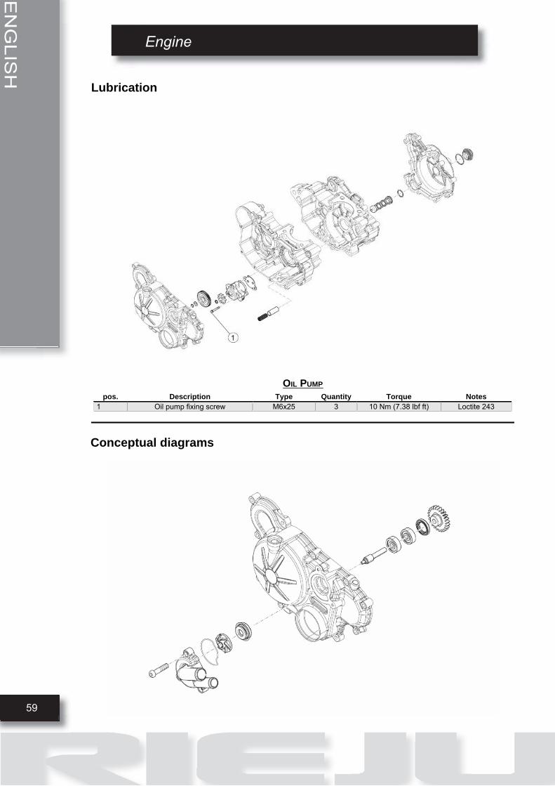
Lubrication
OIL PUMPpos. Description Type Quantity Torque Notes
1 Oil pump fixing screw M6x25 3 10 Nm (7.38 lbf ft) Loctite 243
Conceptual diagrams

Engine
60
ENGLISH
Removing
• Remove the Seeger ring.
• Remove the pump gear.
• Remove the pump gear.
• Separate the components to inspect
them.

ENGLISH
Engine
61
Inspection
• Measure distance between rotors with
a feeler gauge at the positions shown
in the picture.
CharacteristicOil intake rotorThickness: 13.5 mm (0.53 in)
Oil supply rotorThickness: 8.5 mm (0.33 in)
Standard valuesRadial clearance (1) between points of the rotor:
0.04 mm (0.0015 in)Radial clearance (2) between points of the rotor: 0.08 mm(0.003 in)Radial clearance (3) between rotor 1 and the pump body: 0.04mm (0.0015 in)Radial clearance (3) between rotor 2 and the pump body: 0.05mm (0.0019 in)
Installing
• Refit the oil pump proceeding in re-
verse order of disassembly. Pay atten-
tion to the direction of the rotor, the dot
should stay on the opposite part of the
resting face.


RIEJU, S.A. c/.Borrassà, 41 E-17600 FIGUERES, GIRONA (SPAIN)
Telf. +34 / 972500850 Fax +34 / 972506950 www.riejumoto.com / e-mail [email protected]