centurion c5 m-view monochrome lcd (mv-5-c) · mv-5-c display – back side the leds are located...
TRANSCRIPT

00-02-1031 2019-08-07 Section 50
Centurion™ C5
M-VIEW™ Monochrome LCD (MV-5-C)
Operations Manual

BEFORE BEGINNING INSTALLATION OF THIS FW MURPHY PRODUCT:
Please read the following information before operating the Centurion controller. This installation information is intended for Centurion controller only.
Visually inspect the product for any damage during shipping.
Before proceeding please visit our website and review our support documentation including Wiring the Murphy Way. www.fwmurphy.com/uploaded/WIR_Murphy_Way.pdf
Disconnect all power and be sure machine is inoperative before beginning installation.
Installation is to be done only by a qualified technician of the Responsible Body.
Observe all Warnings and Cautions at each section in these instructions.
Device shall be wired in accordance with NEC, CEC or other local code, as applicable.
Please contact FW Murphy immediately if you have any questions.

For Class I, Division 2:
This equipment is an open-type device and is meant to be installed in an
enclosure suitable for the environment such that the equipment is only
accessible with the use of a tool.
This equipment is suitable for use in Class I, Division 2, Groups A, B, C and D or non-hazardous locations only.
Warning – Explosion Hazard – Do not disconnect equipment unless power has
been removed or the area is known to be non-hazardous.
Warning – Explosion Hazard – Do not replace batteries unless the area is
known to be free of ignitable concentrations.
For AEx/Ex Zone 2:
The equipment shall only be used in an area of pollution degree 2, as defined in IEC 60664-1.
The equipment shall be installed completely within an enclosure that provides a minimum ingress protection of IP 54 in accordance with UL 60079-0 and only accessible by the use of a tool.
Transient protection shall be provided that is set at a level not exceeding 140% of the peak rated voltage value at the supply terminals to the equipment. This protection is supplied internal to the equipment. No additional protection is required.
The wire size, torque rating of 12-24 AWG, 0.37-0.44 ft.-lbs. and suitable supply wire temperature rating of 96ºC minimum shall be provided for the input power terminal block.

THIS PAGE INTENTIONALLY LEFT BLANK

Table of Contents
Introduction .................................................................................................................................................................... 1
Product Description................................................................................................................................... 1
Led Indicators ........................................................................................................................................... 1
MV-5-C Display Features ............................................................................................................................................. 4
Home Screen /Landing Page .................................................................................................................... 4
Navigation Keys ........................................................................................................................................ 5
Reading the Screen .................................................................................................................................. 7
Maneuvering in Edit Mode ........................................................................................................................ 8
Status and Mode of the Controller ............................................................................................................ 9
FN Screen ................................................................................................................................................. 9
Password ...................................................................................................................................................................... 10
Passwords and Screen Access .............................................................................................................. 10
Before Starting the Equipment for the First Time ................................................................................................. 11
Setup – MV-5-C Display ......................................................................................................................... 11
Operational Screens ................................................................................................................................................... 14
User-Configurable Screens .................................................................................................................... 14
Map of Operational Screens ................................................................................................................... 14
FW Murphy Logo Screen ........................................................................................................................ 14
Corporate and Configuration Information Screen ................................................................................... 15
Bootloader and Firmware Information Screen ........................................................................................ 15
Digital Input Status Screen ..................................................................................................................... 15
Temp Input Status Screen ...................................................................................................................... 16
Shutdown History Screen ....................................................................................................................... 16
Shutdown Snapshot Screen ................................................................................................................... 16
Event History Screen .............................................................................................................................. 17
Active Alarm Screen ............................................................................................................................... 17
Gage Display Screen .............................................................................................................................. 18
Line-by-Line Screen ................................................................................................................................ 18
Custom Control Loop Screen ................................................................................................................. 18
Rod Load Screen .................................................................................................................................... 19
Setup Screens and Menus......................................................................................................................................... 20
Setpoints Setup Screen .......................................................................................................................... 21
General Timer Setup Screen .................................................................................................................. 22

State Timer Setup Screen ...................................................................................................................... 23
Maintenance Timer Setup Screen .......................................................................................................... 23
Control Loop Setup Screen .................................................................................................................... 24
Miscellaneous Setup Screen .................................................................................................................. 27
Digital Input Setup Screen ...................................................................................................................... 28
Pulse Input Status Screen ...................................................................................................................... 28
Digital Output Setup Screen ................................................................................................................... 29
Analog Inputs Setup Screen ................................................................................................................... 30
Analog Outputs Setup Screen ................................................................................................................ 31
Temperature Inputs Setup Screen .......................................................................................................... 32
Rod load Setup Screen ........................................................................................................................... 33
Display Board Status Screen .................................................................................................................. 34
MVIEW Communication Status Screen .................................................................................................. 35
Centurion Communication Status Screen .............................................................................................. 36
Real Time Clock Setup Screen ............................................................................................................... 36
Super User Menu Screen (Super User Password Protected) ................................................................ 37
Centurion Serial Ports Screen (Super User Password Protected) ......................................................... 38
Centurion CAN Ports Screen (Super User Password Protected) ........................................................... 38
Centurion Ethernet Screen (Super User Password Protected) .............................................................. 39
Centurion EMMC Log Files Screen (Super User Password Protected) ................................................. 39
MVIEW Serial Ports Screen (Super User Password Protected) ............................................................ 40
MVIEW CAN Ports Screen (Super User Password Protected) .............................................................. 40
MVIEW Ethernet Screen (Super User Password Protected) ................................................................. 41
MVIEW Static Block Screen (Super User Password Protected) ............................................................ 41
Communications ......................................................................................................................................................... 42
Display Communication Ports ................................................................................................................. 42
Downloading Configurations and Firmware Updates ............................................................................. 42
Replacement Parts and Assemblies ........................................................................................................................ 43
Accessories .................................................................................................................................................................. 43
Centurion Configuration Tool Software .................................................................................................. 43
Glossary ........................................................................................................................................................................ 43

Section 50 00-02-1031 2019-08-07 - 1 -
Introduction
Product Description
The Centurion configurable controller is a display and controller combination expressly designed to meet the requirements of three specific kinds of applications:
Screw Compressors
Reciprocating Compressors
Pumps
The heart of the Centurion system is the main input/output (I/O) module or controller, which can be mounted on a standard DIN rail. While it is designed to work with any Modbus (Master) compliant HMI (Human Machine Interface) or with no operator interface at all, it is optimally configured and field-configurable using the Centurion Configuration Tool, powerful software developed to configure the controller. Parameters can be modified in the field without special need for laptop or software by utilizing FW Murphy’s specially programmed M-VIEW controller display.
The controller is designed to monitor, control, protect and optimize small-to medium-sized gas operated compressors and pumps in the field. Proper operation is maintained by monitoring setpoints and digital, analog and temperature input points and providing the logic to take corrective and/or proactive steps.
The controller also allows for controlled shutdown and no-flow monitoring as well as auto start up and engine control capabilities.
The controller provides real-time data via communications ports to a connected display and/or supervisory system. This advanced system offers multiple options for remote communications and operation. The industry standard Modbus RTU or Modbus TCP/IP protocol means greater support for a wide variety of communication equipment including radio and satellite communications systems.
Led Indicators
MV-5-C Display – Front Side
Please be aware of the following conditions and the resulting LED appearances:
If the unit has an invalid application or needs to sync (M-VIEW Replacement only), the Red LED is Off and the Amber LED will Flash.
When the bootloader exits to run the application, the Red and Amber LEDs are turned Off.
Section 50 00-02-1031 2019-08-07 - 2 -
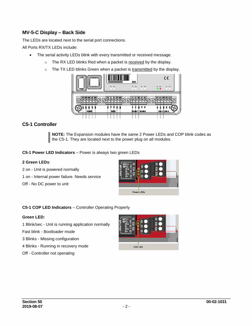
MV-5-C Display – Back Side
The LEDs are located next to the serial port connections.
All Ports RX/TX LEDs include:
The serial activity LEDs blink with every transmitted or received message.
o The RX LED blinks Red when a packet is received by the display.
o The TX LED blinks Green when a packet is transmitted by the display.
C5-1 Controller
NOTE: The Expansion modules have the same 2 Power LEDs and COP blink codes as
the C5-1. They are located next to the power plug on all modules.
C5-1 Power LED Indicators – Power is always two green LEDs
2 Green LEDs:
2 on - Unit is powered normally
1 on - Internal power failure. Needs service
Off - No DC power to unit
C5-1 COP LED Indicators – Controller Operating Properly
Green LED:
1 Blink/sec - Unit is running application normally
Fast blink - Bootloader mode
3 Blinks - Missing configuration
4 Blinks - Running in recovery mode
Off - Controller not operating

Section 50 00-02-1031 2019-08-07 - 3 -
C5-1 Digital Input LED Indicators – Digital Inputs
Green LED:
On - Input active (DC+ or -)
Off - Input active (open)
C5-1 Digital Output LED Indicators – Relay Outputs, FET DC+, FET DC-
Green LED:
On - Output on
Off - Output off
C5-1 Communication LED Indicators - RS232, RS485, CAN bus
RED LED:
Flash - Unit is transmitting data to device
Off - No communication active
GREEN LED:
Flash - Unit is receiving data
Off - No communication active
RS232 RS485 CAN bus
C5-1 DIP Switch Setting
Switch 1-8: Modbus Slave Address function for RS485-2 / RS232-2
Selectable 1-253
If set to address 0, RS485-2 and RS232-2 ports default to 9600 baud.
Set to address 1 to connect to the controller if settings are not known. This is the
default setting from the factory.
Switch 9: Set to ON to enable CAN1 line termination if C5-1 is at the end of the CAN bus
network.
Switch 10: Set to ON to enable CAN2 line termination if C5-1 is at the end of the CAN bus network

Section 50 00-02-1031 2019-08-07 - 4 -
Display Features
The display module is a highly integrated operator interface specially programmed to complement and support the Centurion controller. The primary purpose of the display is to:
view controller operational information
view/edit controller operational parameters
send commands to controller, such as stop, edit and reset
Home Screen / Landing Page
Your default Home Screen / Landing Page is determined by the first page configured in the Centurion
configuration, and may look similar to this example.

Section 50 00-02-1031 2019-08-07 - 5 -
Navigation Keys
The keys actions are relative to the location of the cursor and the screen being displayed.
The following table describes the keys and their function for each screen type:
Operating Status screens
Setup screens (password required)
Edit screens (password required)
Key ID Description
HOME
Operating Status Screen - Allows the user to get to the first line of the current screen,
if pressed again, to get to the default operating status screen. Set Up Screen - -Allows the user to get to the first line of the current screen, if pressed
again, to get to the first setup screen. Edit Screen - No associated action.
ESC/ACK
Operating Status Screen - Acknowledges all active messages and alarms displayed in
the active alarm screen.
Set Up Screen - Exit Setup mode.
Edit Screen - Exit without saving changes to the current configuration.
Fn (Function Key)
Operating Status Screen - Enter “Function mode” and display a dialog box with
additional available functions. Automatically cancels upon moving to the next mode or if no subsequent function is chosen within five seconds.
Set Up Screen - No associated action.
Edit Screen - No associated action.
Control Loop Screens - Press FN to toggle Control Loop mode between Auto and
Manual.
SETUP/
ENTER
Operating Status Screen - Enter Setup Mode.
Set Up Screen - Enter Edit mode or Submenu.
Edit Screen - Accept and save changes made to a current parameter before exiting edit
mode.
RESET
Operating Status Screen - Reset any active timers and alarms/faults.
Set Up Screen - No associated action.
Edit Screen - No associated action.
RUN/STOP
Operating Status Screen - Initiate or cancel a start sequence. Set Up Screen - Cancel a start sequence. Edit Screen - Cancel a start sequence.

Section 50 00-02-1031 2019-08-07 - 6 -
Key ID Description
ARROW UP
Operating Status Screen - Scroll up one line. Automatically repeats if held down
continuously until reaching the first line.
For history screens, scrolls up one history (for example: shutdown or event).
Set Up Screen - Scroll up one line. Automatically repeats if held down continuously until reaching the first line.
Edit Screen - Increase the digit selected by the cursor (from 0 to 9). The user will not be
allowed to increase the selected digit if it would result in exceeding range limits. Toggle the value in a list of options if editing a non-numeric value.
Control Loop Screens - Press this in Manual mode to increment the output manually.
ARROW DOWN
Operating Status Screen - Scroll down one line. Automatically repeats if held down
continuously until reaching the final line.
For history screens, scrolls down one history (i.e. shutdown or event).
Set Up Screen - Scroll down one line. Automatically repeats if held down continuously
until reaching the final line.
Edit Screen - Decrease the digit selected by the cursor (from 0 to 9). The user will not
be allowed to decrease the selected digit if it would result in exceeding range limits. Toggle the value in a list of options if editing a non-numeric value.
Control Loop Screens - Press this in Manual mode to decrement the output manually.
ARROW LEFT
Operating Status Screen - Display previous screen. Automatically repeats if held down
continuously until reaching the first screen.
Set Up Screen - Display previous screen. This key has no action when in a submenu.
Edit Screen - Move the cursor left one position when a numeric value is displayed.
ARROW RIGHT
Operating Status Screen - Display next screen. Automatically repeats if held down
continuously until reaching the final screen.
Set Up Screen - Display next screen. This key has no action when in a submenu.
Edit Screen - Move the cursor right one position when a numeric value is displayed.
TEST
Operating Status Screen - Enter test mode and start test timer. This is not applicable
in shutdown mode.
Set Up Screen - No associated action.
Edit Screen - No associated action.
TIMER “0”
Operating Status Screen - Zero displayed timer (global timers, state timers, etc.)
Set Up Screen - No associated action.
Edit Screen - No associated action.
Section 50 00-02-1031 2019-08-07 - 7 -
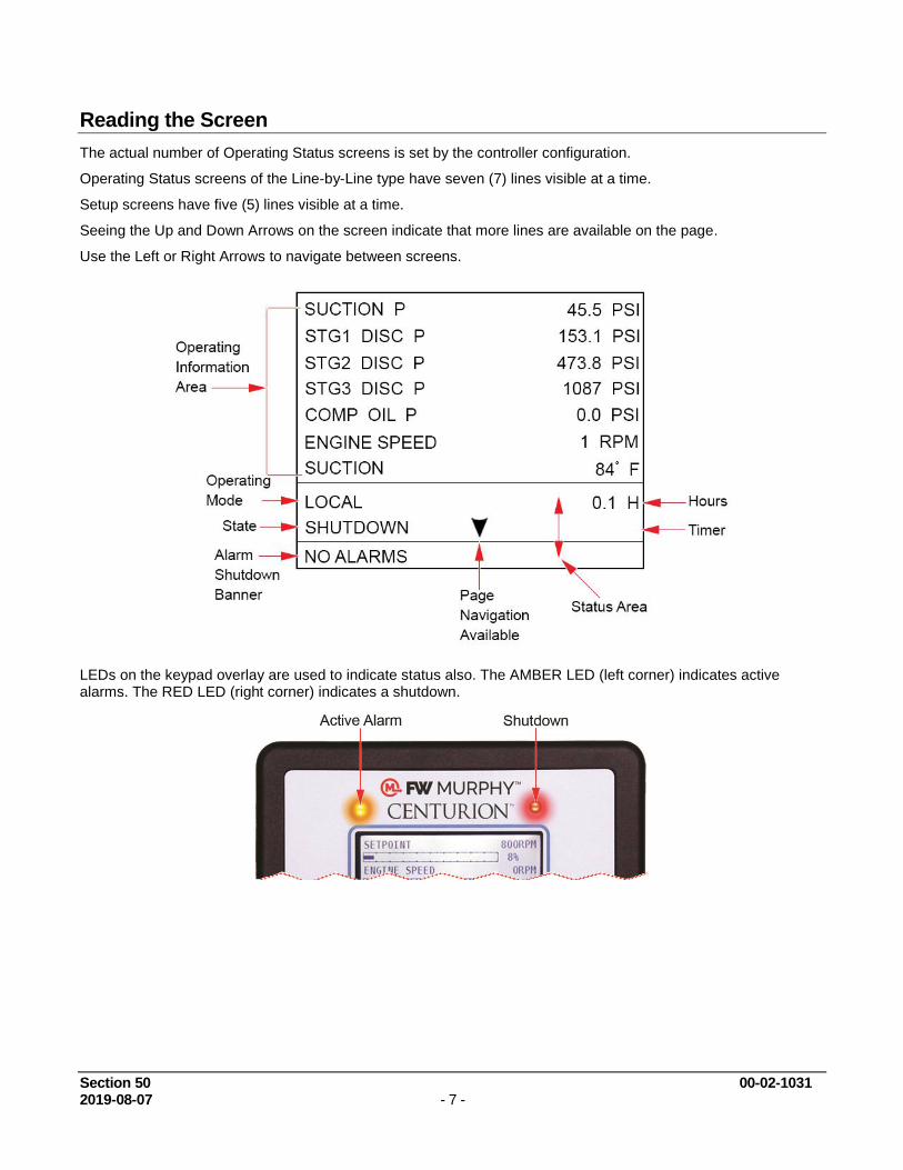
Reading the Screen
The actual number of Operating Status screens is set by the controller configuration.
Operating Status screens of the Line-by-Line type have seven (7) lines visible at a time.
Setup screens have five (5) lines visible at a time.
Seeing the Up and Down Arrows on the screen indicate that more lines are available on the page.
Use the Left or Right Arrows to navigate between screens.
LEDs on the keypad overlay are used to indicate status also. The AMBER LED (left corner) indicates active alarms. The RED LED (right corner) indicates a shutdown.
Section 50 00-02-1031 2019-08-07 - 8 -
Maneuvering in Edit Mode
In the edit mode you may see the curser blinking where it’s being edited. In some instances, a word rather than a value is represented and you may choose one or the other, such as Yes or No, On or Off in the Edit Mode.
The edit curser rest on the far right digit. Example 00000.
Press the Up / Down Arrows to add a number value.
Press the Left / Right Arrow to move the edit cursor to the next digit and so on.
Press Setup / Enter to save, once all numbers are placed. Example 00164.
Some digits may not be allowed to increase if it would result in exceeding range limits.
Values which can be positive or negative, will have a sign (±) to the left of the number.
o To change the sign value, move the cursor to the sign using the Left Arrow key and toggle between + and – using the Up and Down Arrow keys.
o If the range of the value will exceed range limits, the sign may not be allowed to change. In this case, try reducing the number by decreasing the left most digit by one or more and attempt to change the sign again.
Press the Up / Down Arrows to toggle between choices, such as On/Off or Yes/No.
Press Setup / Enter to save, once all choices are placed. Example Yes/No.
Press the ESC key to discard any changes and keep the original value prior to entering the Edit Mode.
NOTE: A select few menu parameters change in real-time when the value is changed.
These will be noted in this document.
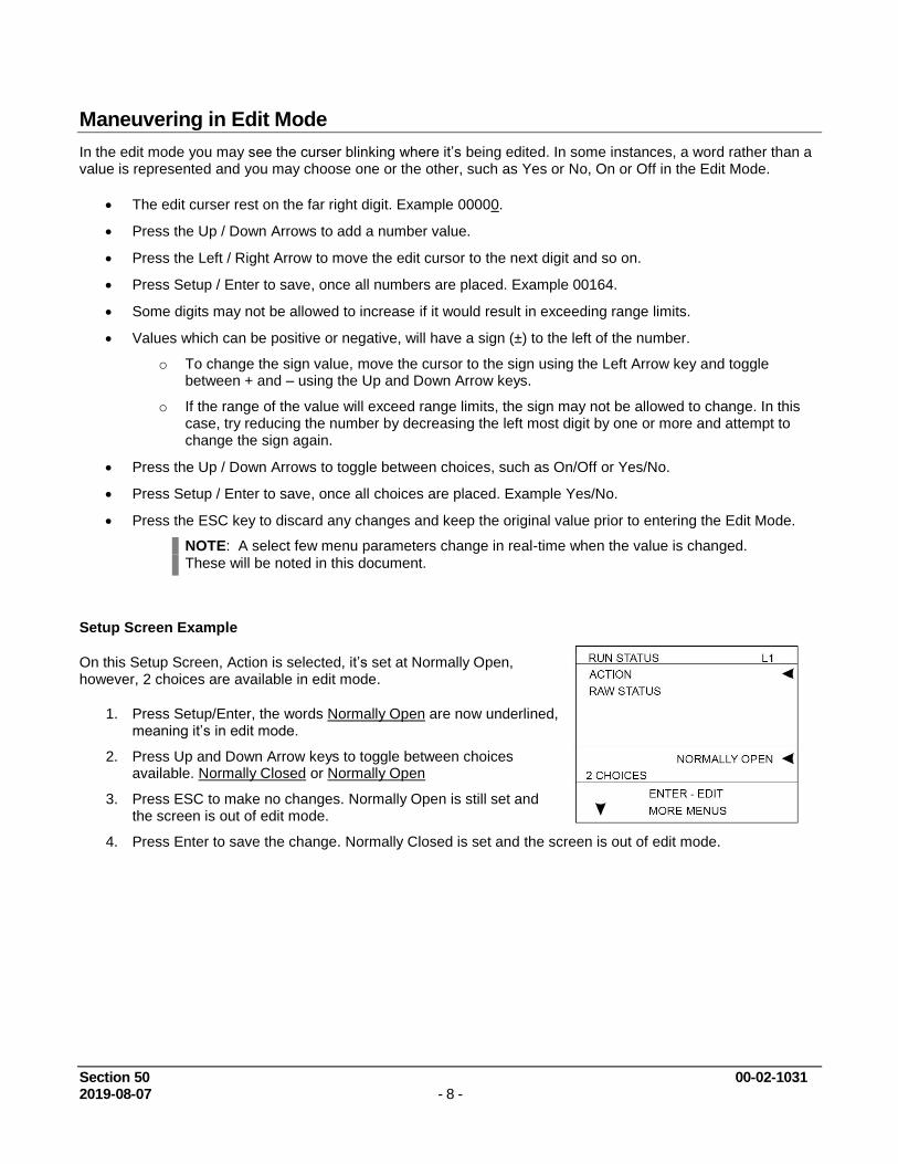
Setup Screen Example
On this Setup Screen, Action is selected, it’s set at Normally Open, however, 2 choices are available in edit mode.
1. Press Setup/Enter, the words Normally Open are now underlined, meaning it’s in edit mode.
2. Press Up and Down Arrow keys to toggle between choices available. Normally Closed or Normally Open
3. Press ESC to make no changes. Normally Open is still set and the screen is out of edit mode.
4. Press Enter to save the change. Normally Closed is set and the screen is out of edit mode.

Section 50 00-02-1031 2019-08-07 - 9 -
Status and Mode of the Controller
Local and Remote are the two Operating Modes of the controller. The operation may differ depending on what Mode the controller is currently displaying.
The Mode can be changed by pressing certain keys, if the configuration allows for Remote mode.
Pressing Reset or Run/Stop is a Local function and will change the Mode to Local if it is in Remote.
Pressing the Fn key before pressing Reset or Run/Stop is a Remote function and will change the Mode to Remote if it is in Local.
FN Screen
Pressing the Function (Fn) key from any Operational screen will display the Function Menu screen momentarily to gain quick access to other pages.
Press the down arrow to select a screen and press enter to open it. Only available function key commands will be displayed. A prompt to enter a password may appear for some screens to open.
Remote mode commands are available only while the Fn key is pressed.
If the Fn key is not followed by another key press in five seconds, function mode will time out, and the screen will return to the previous screen.

Section 50 00-02-1031 2019-08-07 - 10 -
Password
Passwords and Screen Access
Some settings are password protected, including the setup screens.
There are two separate levels of passwords to accommodate several security needs:
Standard password – Allows access to some features except the super user menu and setup editing.
Super User password – Adds the super user menu and setup editing to the standard menus.
Where to Log ON and OFF
The password screen is displayed whenever security access is required for an action, and you may log in from there. Default passwords are 164 for operator or 133 for super.
1. To access the password screen anytime, from the Home Screen / Landing Page, press the Setup / Enter key to open the Password screen. The edit curser rest on the far right digit. Example 00000.
2. Press the Up / Down arrows to add a number value.
3. Press the Left / Right arrow to move the edit cursor to the next digit and so on.
4. Press Setup / Enter to save, once all numbers are placed. Example 00164.
NOTE: After three minutes without activity, the keypad returns to the default operational
screen, and a password must be re-entered to return to the setup and edit menus.
Once you have entered with the default password, we recommend you change passwords for better security. See the explanation on the Super User Menu page.
Standard Password Example Super User Password Example

Section 50 00-02-1031 2019-08-07 - 11 -
Before Starting the Equipment for the First Time
Setup – MV-5-C Display
Read and follow steps in the order listed.
1. Locate the system drawing inside the panel and verify its drawing number matches the sticker on the lower front panel.
2. Locate the legend of the drawing and find the configuration description. Record this description.
3. Power up the Centurion System.
a. Allow time for the display to boot up and land on the Home Screen / Landing Page, approximately 15 seconds.
b. From the Centurion Home Screen / Landing Page, touch the Arrow key to scroll left until you find the screen FW Murphy – MVIEW screen.
c. Verify that the configuration description matches the one you previously recorded from the drawing legend.

Section 50 00-02-1031 2019-08-07 - 12 -
4. Press the Setup Enter key to open the Password screen.
a. Use the Arrow keys to enter your password. Default passwords are Operator 164, Super User 133. If further details are needed, see Display Passwords.
5. Once the password is entered, the display opens the Setpoints Setup screen. Use the right and left Arrow keys to find the screen you want to view / edit.
Map of the Setup Screens for MV-5-C Display
>Home/Setup Enter Key/Password/Setpoints Setup/Arrow Key scroll to screen<
Setpoints Setup
General Timer Setup
State Timer Setup
Maintenance Timer Setup
Control Loop Setup
Miscellaneous Setup
Digital Input Setup
Pulse Input Status
Digital Output Setup
Analog Inputs Setup
AnalogOutputs Setup
TemperatureInputs Setup
Rod Load Setup
DisplayBoard Status
MVIEW Comm Status
Centurion Comm Status
Real Time Clock Setup
Super User Setup
Centurion Serial Ports
Centurion Can Ports
Centurion Ethernet
Centurion EMMC Log
MVIEW Serial Ports
MVIEWCAN Ports
MVIEW Ethernet
MVIEW Static Block
6. Open the following list of screens to verify or change the factory settings as needed for your site location.
a. We suggest you record these values in the Sequence of Operation. This gives you a reference of any changed settings from the factory default.
b. Select and enter each active item on the screen and verify its set values.
i. Edit values as needed using the active Arrow keys.
ii. Press the Setup / Enter key to change or accept the value.
iii. Press the ESC / ACK key to go back one page without change.
iv. Record any changes.
v. Repeat these steps until all screens listed below are verified for your site location.
Setpoints Setup
Control Loop Setup
Analog Input Setup
General Timer Setup
State Timer Setup
Temperature Inputs Setup
Rod Load Setup

Section 50 00-02-1031 2019-08-07 - 13 -
7. Start the unit.
a. Clear any Alarms Class A (always armed) faults from the system. On the display, the Unit State will read Panel Ready if no Class A shutdown condition exist.
b. Press and hold the Run Stop key on the display for 2 seconds. This will initiate the start cycle. Depending on your configuration, the Centurion will send signals to possibly prelube the equipment, check pre-starting permissives, and then signal the driver to start the equipment. Confirmation of running may be in the form of RPM signal or digital switch input feedback. Once running signal is confirmed, the Centurion will be in a running condition. Class B and S lockout timers will begin timing to faults that require time lockout. Additional warmup and load permissives will be monitored as configured for the package prior to enabling any load control.
c. After all preload permissives have been achieved, such as oil or water temperatures, and possible minimum warmup times, the Unit State will read Loaded and will continue until the stop button is pressed, RPM is lost or a fault condition exist.
Faults, Stops and Alarms
Normal Stop
When a normal stop is issued and the unit is running, the system will start a normal shut-down sequence.
1. To issue a normal stop, press and hold the Run Stop key on the display for 2 seconds.
2. On the display, the Unit State will read Cooldown, and the Cooldown state delay will begin timing (if configured).
3. After the Cooldown is completed, the Unit State will read Stopping.
4. When everything has been recognized as back to normal the Unit State will read Panel Ready.
Fault Shutdown
The Centurion will continually monitor for Fault or ESD shutdown events which require the equipment to stop immediately or prevent it to start.
On the display, the Unit State will read Shutdown and the Alarm Shutdown banner on the bottom of the screen shows the shutdown message in a firstout fashion, and the LED on the upper part of the display will illuminate Red.
The cause of the event is recorded and can be viewed on the Shutdown History screen with time and date of occurrence.
1. The Shutdown History screen displays information of the fault.
a. <Centurion Home Screen / FN / Shutdown History>
2. The Shutdown Snapshot screen displays the values of the unit running at the time a fault occurred.
a. <Centurion Home Screen / FN / Shutdown History / Right Arrow to scroll >
3. Once the corrections are made, clear the Shutdown condition by pressing the Reset key on the display.
4. Always make corrections on the unit before attempting to restart the equipment.
Alarms
If an alarm condition is detected, the Alarm Shutdown banner on the bottom of the screen shows the active alarm messages in the system, and the LED on the upper part of the display will illuminate Amber. Alarms may be configured as self-clearing or as requiring acknowledgement. Self-clearing alarms will auto clear if no longer present. Alarms requiring acknowledgement will persist until the ACK key is pressed.
You can view up to 20 active alarms on the Active Alarms screen.
o <Centurion Home Screen / FN / Active Alarms>
Press the ESC ACK key to acknowledge the Active Alarm.

Section 50 00-02-1031 2019-08-07 - 14 -
Operational Screens
User-Configurable Screens
The Centurion has (9) user-configurable pages of (4) types. The Centurion Configuration Tool software allows users to configure up to nine (9) screens with controller input signal groupings. Possible custom screen types may include:
a) Custom Line by Line allows user to display process data in a list format with description and value.
b) Custom Gage allows user to display four (4) most important pieces of data on a 2 x 2 table in larger font.
c) Custom Control Loop allows user to display Control Loop functions. The control output will be displayed as a percentage of the range.
d) Custom Generic Register allows user to display up to 20 items on a page that can be mapped to the Centurion Modbus map and given a label.
For more information on configuring the optional screens through the Centurion Configuration Tool, please refer to the Configuration Tool Quick Start Guide.
Map of Operational Screens
From the Home Screen / Landing Page, use the left and right arrows to view the Operating Screens. A password is not required to view these screens.
Some screens are application specific and may not be used.
* When Configured
Logo Screen
ConfigurationScreen
Firmware Bootloader
Digital input /Output Status
TemperatureInput Status
ShutdownHistory
ShutdownSnapshot
EventHistory
Active Alarms
Home Screen /Landing Page
Line-By-Line
ControlLoop
RodLoad *
NOTE:Based on configuration, up to 9 custom screens here.
FW Murphy Logo Screen
The FW Murphy logo is the first screen in the sequence of display screens and can be viewed by holding down the left arrow until scrolling left ceases.
Section 50 00-02-1031 2019-08-07 - 15 -
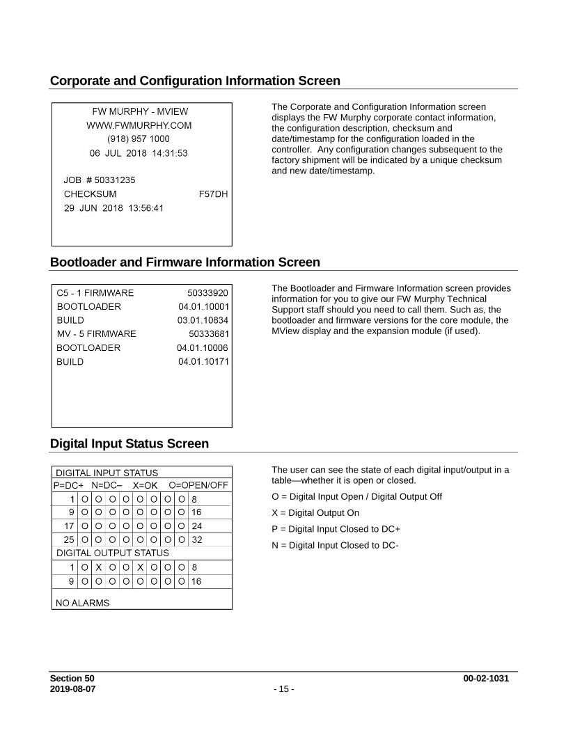
Corporate and Configuration Information Screen
The Corporate and Configuration Information screen displays the FW Murphy corporate contact information, the configuration description, checksum and date/timestamp for the configuration loaded in the controller. Any configuration changes subsequent to the factory shipment will be indicated by a unique checksum and new date/timestamp.
Bootloader and Firmware Information Screen
The Bootloader and Firmware Information screen provides information for you to give our FW Murphy Technical Support staff should you need to call them. Such as, the bootloader and firmware versions for the core module, the MView display and the expansion module (if used).
Digital Input Status Screen
The user can see the state of each digital input/output in a table—whether it is open or closed.
O = Digital Input Open / Digital Output Off
X = Digital Output On
P = Digital Input Closed to DC+
N = Digital Input Closed to DC-

Section 50 00-02-1031 2019-08-07 - 16 -
Temp Input Status Screen
t
The user can see the state of each temperature input in a table—whether it is OK or has a wiring fault.
X = OK
p = Wire Fault Leaking to DC+ (input still able to be read, but some error is being introduced)
n = Wire Fault Leaking to DC- (input still able to be read, but some error is being introduced)
P = Wire Fault Short to DC+ (input not able to be read)
N = Wire Fault Short to DC- (input not able to be read)
Shutdown History Screen
The history of the shutdowns are displayed on this screen, with the most recent at the top of the list and the oldest at the bottom.
The number displayed in the top right corner indicates how many entries are in the list.
Each event is displayed with the event label on one line and the real time clock and hour meter reading on the following line.
Shutdown Snapshot Screen
The shutdown snapshot screen is a capture of the values displayed on the line-by-line custom screen at the time of a Fault SD or ESD event. These values will be retained and display on the shutdown snapshot screen until the next Fault SD or ESD event occurs. A “---“ displayed instead of a value indicates the shutdown snapshot has not captured any data. Fault snapshots are taken only while the equipment has been called to start/run. This behavior ensures that repeated attempts to reset a fault will not “clear” a previous run cycle’s fault snapshot.
NOTE: Only the first two line-by-line screens
configured will be captured on the fault snapshot page. If no line-by-line custom screens are configured, the shutdown snapshot will not function.

Section 50 00-02-1031 2019-08-07 - 17 -
Event History Screen
The history of the last 32 events is displayed on this screen, with the most recent at the top of the list and the oldest at the bottom.
The number displayed in the top right corner indicates how many entries are in the list.
Events include shutdowns, starts, stops, resets, etc.
The user easily can view the events (alarms, etc.) logged before and after a shutdown.
Each event is displayed with the event label on one line and the real time clock and hour meter reading on the following line.
Active Alarm Screen
All active alarms and warnings will be displayed on this screen.
Unacknowledged alarms will be preceded by an asterisk, and acknowledged alarms will clear the asterisk.
Pressing ACK on this screen will acknowledge all active alarms.
The top right corner will indicate the number of alarms and which line the cursor is currently on. Example: 3/10 indicates 10 alarms, and the cursor is on line 3 of the list. A maximum of twenty (20) active alarms will be displayed.
NOTE: Alarms are warnings based on setpoints
and/or digital inputs which are separate from shutdowns that allow the equipment to continue to run.
Alarm / Shutdown Banner
This screen shows the alarm / shutdown annunciation as it will appear on most Operating Status screens.
The message(s) will be visible at the bottom line of the status screen area and then briefly clear once a second.
This will continue until alarms are acknowledged and/or shutdowns are cleared.
If there is more than one unacknowledged alarm active, each alarm will be displayed for one second each until acknowledged.
Pressing the Fn key followed by the ACK key will switch to the active alarms screen.

Section 50 00-02-1031 2019-08-07 - 18 -
Gage Display Screen
This is an example of a custom gage display.
This display provides larger characters for easier viewing as well as a means to prominently display items of interest.
Line-by-Line Screen
This is an example of a custom line-by-line status screen.
If the parameters do not fit in the viewable area of the screen, up/down arrow icons will appear at the bottom of the screen to indicate the ability to scroll up or down to see additional parameters.
Custom Control Loop Screen
The user may choose to display any configured Control Loop functions in this convenient format. The control output will be displayed as a percentage of the range.
Press the Fn key on this page to toggle the mode between AUTO and MANUAL modes of control loop operation.
If the Control Loop is in MANUAL, the UP and DOWN arrow keys will adjust the output directly to manually make adjustments to the desired setting.

Section 50 00-02-1031 2019-08-07 - 19 -
Rod Load Screen
If Rod Load calculations have been enabled on the Centurion Configuration, the last page to the right will contain the Compressor Rod Load information.
The calculated tension and compression forces on the rod are displayed in Imperial or Metric units as configured by the user.
There is support for 1 through 6 throws of rod load calculation.

Section 50 00-02-1031 2019-08-07 - 20 -
Setup Screens and Menus
After entering your password, use the right and left arrow to view the Setup Screens available at your security level.
The setup screens provide access to system parameters. These settings can be modified with appropriate password access.
The two bottom lines in the setup screens list navigation and command options that are available with the selected item.
READ ONLY
ENTER – EDIT
ENTER – ACCEPT
ESC – CANCEL
MORE MENUS
ENTER - SUBMENU

Section 50 00-02-1031 2019-08-07 - 21 -
Setpoints Setup Screen
Up to 192 setpoints may be configured in the system by the Centurion Configuration Tool software. The values for the setpoints are user editable.
Setpoints are data entries used in greater than or less than comparisons of signals based on variable input types such as MPU, analog or thermocouples. The setpoint is a threshold, exception or any other out-of-limit event that can be configured to take a required action. Multiple setpoints are often applied to a process, and they may be configured as often as needed to meet changing conditions.
Common alarm and shutdown setpoints a user might have configured include:
High shutdown (High-High)
High warning (High)
Low warning (Low)
Low shutdown (Low-Low)
To edit a configured setpoint:
a) Select the setpoint group submenu that requires editing. The configuration listing provided will include a listing of all setpoints and their respective number.
b) Assign numeric threshold that if crossed, triggers the setpoint.
b) Adjust the sign of the threshold value as plus (+) or minus (-) by moving the cursor to the sign symbol position and use the up and down keys to toggle the sign.
NOTE: Setpoints 1-16 and 17-32 can also have
debounce timing applied as a signal filter. The setpoint comparison must be sustained through this time delay to see the setpoint as true. This time filter can be used to ignore transients of short duration.

Section 50 00-02-1031 2019-08-07 - 22 -
General Timer Setup Screen
User may edit all general purpose timers. Generally, global timers affect driver operation. They also help define an event arming condition.
B1: All event types can be associated with, and locked out
by, a Bx timer. B1 is the first global timer used for delaying an event condition detection. The timer starts and runs in the running States of the controller operation. B1 is also known as the Lockout Timer, start bypass or start/run timer.
B2: The second global timer used for delaying event condition detection. B2 is also known as a secondary
Lockout Timer.
C2: The delay after reaching the Run Loaded State that allows Class C2 events to arm. Class C events require
a clear reading sustained for 2 seconds to arm. This time used as stabilization time for any manual loading to be
operated and the load to stabilize on the machine.
S1-4: Users have up to four (4) options to assign additional special global timers to signals. The Sx timers begin
concurrently with the Bx timers.
No Flow: The global delay used for delaying the triggering of a no-flow event. This global no flow timer is
enabled after B1 expires and begins timing after any of the pulse transition times configured in the digital input dialog expires.
Test: Time given to allow for maintenance testing of end devices without triggering a fault or shutdown condition.
The timer initiates when switched to test mode.
Ignition On Delay: Time delay before the assigned ignition output turns on. This is typically used to delay
ignition until engine has started cranking (also known as a purge delay).
Fuel On Delay: Time delay before the assigned fuel valve output is turned on. This is typically used to delay fuel until ignition has been turned on.
Ignition Off Delay: Time delay before the assigned ignition output turns off. This is typically used to burn
remaining fuel vapors after the fuel valve is turned off.
Power Save Timer: Time delay that begins timing upon shutdown or stopping of the equipment, and will turn off a
configurable Power Save digital output that can be used to remove power to the controller or other equipment to save batteries.

Section 50 00-02-1031 2019-08-07 - 23 -
State Timer Setup Screen
User may edit all state timers if marked in use. State 1 – Panel Ready and 23 – Shutdown are Read Only and cannot be edited. The states used for a given application are configured by the Centurion Configuration Tool software.
When the state timeout value is reached, the state logic proceeds to the next In Use state. A state timeout may also be configured to trigger a fault event such as a prelube permissive failure; however, the operation depends on the configuration.
Maintenance Timer Setup Screen
The user may access and edit the ten (10) maintenance duration presets and time remaining settings, if used by the configuration. All maintenance timer units are in hours.
NOTE: These are configured by the Centurion
configuration tool software and must be manually initialized in Centurion display.
When the timer reaches 0 hours an event may be configured to alarm or generate a message event that maintenance is required.
Start / Restart Maintenance Timers
To initialize or restart the timers, position cursor on TIME REMAINING and press the reset key.

Section 50 00-02-1031 2019-08-07 - 24 -
Control Loop Setup Screen
Users may view and edit up to eight (8) configured control loops. The settings on this page will differ depending on the type of control configured for the system. The control loops all operate on the principle of a 0-100% calculated output with special considerations for the Digital loop types. Four control loop types are possible.
a) Analog and Digital types use a closed loop PID calculation to calculate the output value, in which a process variable is maintained at a desired setpoint with the PID generating a 0-100% corrective action to the process. The ultimate goal of the PID is to reduce the error to zero effectively maintaining the control setpoint (e.g. speed, load, pressure). PID calculations attempt to model the process being controlled by allowing tuning for the dynamics of the process based on the present (Proportional), past (Integral) and future (Derivative) error of the loop. The controller uses the parallel form of the PID equation as follows:
% Output = Kp(Error) + Ki∫(Error)dt + Kd×dError∕dt
b) 2 Pulsed Digital type uses a closed loop pulse equation that calculates the On time for either the increase or decrease digital output based on the control error.
% Output = (Error x Kp) + 50%
The ultimate goal of the loop is to reduce the error to zero effectively maintaining the control setpoint (e.g. speed, load, pressure). The control algorithm is centered at 50% output. At 50% output, neither digital output is on. The control loop will either add to 50% or subtract from 50% to pulse the increase or the decrease outputs. Larger deviation from 50% will result in longer output pulses.
c) 4-Step Load turns on 4 digital outputs in a 4-step staggered loading scheme with time delays in between the loading steps. The ultimate goal of the loop is to reduce the error to zero while maintaining the control setpoint (e.g. speed, load, pressure). The control loop will turn on the outputs in succession, and the 0-100% control value will step up from 0 to 20%, 40%, 60% and 80% as the time delays expire. If the deadband is reached, the time delays will reset, and no change in control will occur.
d) Open Loop calculates an analog output value using a linear scaling based on a feedback input. In this case, there is no closed feedback and no setpoint to maintain. There are 2 coordinates specified in engineering units for the process being controlled, one for minimum % output and one for maximum % output. A linear scaling function will be applied using these 2 values to range the output between the specified minimum and maximum % settings.
e) Common setpoints to Analog/Digital, 2 Pulsed Digital and 4-Step Load loop types. Open Loop Ramp loop type shares only those setpoints marked with (*).
1. Auto/Manual Mode*: Set the loop to Auto to enable the control. Set to Manual to allow user entry for the control output as a 0.00-100.00% value.
2. Setpoint: Assign the desired value that is to be maintained by the loop. Depending on configuration this may be a variable setpoint based on analog input, not user editable from the display.
3. Deadband: Assign a value around the setpoint during which the loop will not take any corrective action.
4. Minimum Output*: Set the minimum limit on the calculated value during auto control
5. Maximum Output*: Set the maximum limit on the calculated value during auto control.
6. Loop Update time: Loop calculation frequency. This time should be set no shorter than the update rate
for the feedback reading.

Section 50 00-02-1031 2019-08-07 - 25 -
7. Max Rate of Decrease/Increase: This is a maximum slew rate setting for the output change per loop update time.
8. Set Output % (Manual) *: This is the control output value data entry for manual mode.
9. Override 1-3 Ramp time*: Set the interval used to modify the calculated output when a configured override signal is active.
10. Override 1-3 Change %: Set the amount of change either positive or negative required to the calculated output while a configured override signal is active.
NOTE: Override settings are only used when there is a configuration for overriding the control
loop with another process variable. Each control loop may have up to 3 control loop override settings based on setpoint or digital inputs signals going true and false.
11. Display Loop Bar Graph*: Set to yes to show a bar graph page for the control loop as it operates.
12. Ref Line Select*: Setting to select any value to be shown on the Display Loop Bar Graph in addition to the setpoint, feedback and control output values. This setting is useful for showing the process value of a different analog, thermocouple or speed input that may be affected by changes to the PID output. Select from available analog, thermocouple or speed inputs or None to disable the Reference Line Select feature.

Section 50 00-02-1031 2019-08-07 - 26 -
Control Loop Setup Screen (continued)
a) Analog/Digital PID loop specific setpoints:
1. Proportional: Proportional gain tuning for the
control process.
2. Integral: Integral time constant (%/sec) tuning for
the control process. Integration adjusts the output value on the accumulated of the error over time.
3. Derivative: Derivative time (% seconds) tuning for
the control process. Derivative adjusts the output value based on the rate of change of the error over time.
b) 2 Pulse Digital loop specific setpoints:
1. Proportional: Proportional number multiplied by the
error to result in the on time for the pulse. Larger numbers here will result in longer on times for the pulse at a given error.
2. Inc/Dec Max On Time 1/20s: Set the maximum on
times for the calculated on time of the pulse. This is a clipping value applied to the calculated result.
3. Inc/Dec Sample Time 1/20s: Set the fixed off time between pulses. This should be set long enough to allow the results of the previous pulse to have effect on the process before a new pulse is generated.
4. Inc/Dec Xover On Time 1/20s: Set the fixed on
pulse that is generated when the control changes from increasing to decreasing or vice versa. This is optional and typically used to prime hydraulic controls to reverse direction.
5. Inc/Dec Xover Off Time 1/20s: Set the fixed off
pulse that is generated when the control changes from increasing to decreasing or vice versa. This is optional and typically used to prime hydraulic controls to reverse direction.
C) 4. Step Load loop specific setpoints:
1. Input For Min % Out: This is the engineering unit
value for the loop input that will cause the Minimum % output to be calculated. This value will be a pressure, temperature, RPM or other variable signal that controls the output directly.
2. Input For Max % Out: This is the engineering unit
value for the loop input that will cause the Maximum % output to be calculated. This value will be a pressure, temperature, RPM or other variable signal that controls the output directly.

Section 50 00-02-1031 2019-08-07 - 27 -
Miscellaneous Setup Screen
a) Core/Expansion Flywheel Teeth:
Engine: Define a value for flywheel teeth (Pulses Per
Revolution) used to calculate RPM.
Motor: When setpoint set to zero, crank attempts becomes
# of starts per hour (Short cycle limit) for electric motor applications.
b) Hour Meter (0.0-499999.9): Reset or preset the internal
hour meter.
c) Crank Attempts (1-16):
Engine: Define a value for number of crank attempts after which an over-crank sequence signal will be triggered in the system. If the configuration includes an Overcrank event, it will be triggered by this signal.
Motor: Define a value for number of motor start attempts per hour after (Short cycle) which an excess start attempts will be triggered in the system. If the configuration includes an Overcrank/Excess starts event, it will be triggered by this signal.
WARNING: The following cold temperature offset values should only be adjusted by personnel with a full working knowledge of the Centurion in conjunction with calibrated reference equipment.
h) Core CJ Temp: Enter a non-zero value for temperature
adjustment in tenths of a degree to offset the temperature readings.
i) Exp CJ Temp Offset: Enter a non-zero value for
temperature adjustment in tenths of a degree to offset the temperature readings.

Section 50 00-02-1031 2019-08-07 - 28 -
Digital Input Setup Screen
For all configured digital inputs, the user may edit:
a) Signal Type - Select one of three choices;
normally open, normally closed DC+ or normally closed DC-.
b) Signal Filter - Select None to disable filter function for the digital input. This will not disable the digital input for normal operation. Select Pulse for lubricator divider blocks with a proximity switch output. Select DB to debounce or delay input detection for unstable inputs such as surge tank level.
c) Filter Timing - Delay time in seconds for the
selected filter type. For Pulse, this delay is the transition time for the lubricator divider block to cycle. For DB, this is the duration the digital input must remain either ON or OFF before the input will be recognized and accepted as ON or OFF by the sequence. If the input does not remain ON or OFF for the duration of the delay, the timer will reset.
d) Raw Status: The actual measured sensor state.
e) Total Pulsed - Total number of pulses counted when the filter type is set to Pulse. The value is expressed in hundreds of pulses. A displayed reading of 1 is equal to 100 pulses. (*only visible on pulse filter types) It may be reset on this display line as well.
Pulse Input Status Screen
Pulsed inputs are designed to accept a cycling digital output from a lubricator divider block, typically from a general purpose proximity switch.
The user may view information about the pulsed inputs. If a digital input is designated for use as a pulsed input, it will display how much time elapsed before the last transition and how much time has elapsed since that transition. If the input is not designated as a pulsed input, there will be zeros displayed. Both have a maximum value of 999.

Section 50 00-02-1031 2019-08-07 - 29 -
Digital Output Setup Screen
Digital output: For all configured digital outputs, the user
may edit:
a) Action - Select normally open or normally closed.
Normally closed inverts the logic associated with the output if desired.
b) Raw Status: The actual output state.
To force the output, toggling the normally open to normally closed will cause it to invert state.

Section 50 00-02-1031 2019-08-07 - 30 -
Analog Inputs Setup Screen
For all configured analog input devices, the user may edit:
a) Scaled Minimum - Minimum engineering scale for the
input when the raw counts are at the raw count offset reading. Example: 0 PSI for a 0-100 PSI transmitter.
b) Scaled Maximum - Maximum engineering scale for the
input when the raw counts are at the raw count offset + raw count max (total raw counts). Example: 100 PSI for a 0-100 PSI transmitter.
NOTE: To calibrate an analog input, change the raw
offset and max settings. The scaled minimum and maximum settings should match the engineering unit range for the device.
c) Moving Average Samples. (1, 2, 4). Apply averaging
filter to the input.
d) Raw Count Offset. Set the lowest raw analog input
counts seen from the device.
e) Raw Count Span. Set the highest raw analog input
counts span seen from the device. This number is added to the raw count offset to equal the actual raw count reading.
The user can view the raw counts of the analog inputs to calibrate the input by adjusting the offset and max raw count readings.
NOTE: Typical approximate raw readings for 4-20mA input:
4mA = 5243 counts
20mA = 26214 counts (5243 + 20971)
Section 50 00-02-1031 2019-08-07 - 31 -
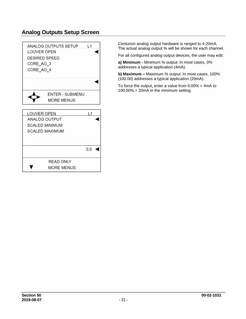
Analog Outputs Setup Screen
Centurion analog output hardware is ranged to 4-20mA. The actual analog output % will be shown for each channel.
For all configured analog output devices, the user may edit:
a) Minimum - Minimum % output. In most cases, 0%
addresses a typical application (4mA).
b) Maximum – Maximum % output. In most cases, 100%
(100.00) addresses a typical application (20mA).
To force the output, enter a value from 0.00% = 4mA to 100.00%.= 20mA in the minimum setting.

Section 50 00-02-1031 2019-08-07 - 32 -
Temperature Inputs Setup Screen
The actual temperature reading in degrees will be shown per channel.
For all configured temperature devices, the user may edit:
a) Temperature: The actual measured sensor reading.
b) Status: Real-time display of any wire faults that may
exist for the sensor.
c) Last Status Error: The last detected wire fault for the
sensor, use this record to troubleshoot intermittent faults, this line will hold the last recorded error.
d) Type. Identify whether the input type should be set to
one of three types: J thermocouple, K thermocouple or 100 OHM Pt RTD.
NOTE: for MX4-R2 even channels can only be selected
as J thermocouple or K thermocouple
e) Offset. Assign an optional thermocouple reading offset value.

Section 50 00-02-1031 2019-08-07 - 33 -
Rod load Setup Screen
Rod Load setup screen is visible if Compressor Rod Load is configured in the Centurion. For each throw setup in the configuration, the user can view and set these parameters.
a) Throw Type: Display for the set action of the compressor throw. If set to Single or Double by the configuration tool, the user may change the action back and forth if the compressor geometry is changed. Blank or Tandem options are Read Only
b) Rod Size: Setpoint displayed in inches or centimeters, depending on the configured Rod Load Units, for the rod size.
c) Suction Pressure: Display for the input channel used as suction pressure for the throw.
d) Suction Pressure Drop: Setpoint in Percent for the pressure drop from the measurement point to the internal cylinder pressures. This is aggregate of valve and piping pressure losses.
e) Discharge Pressure: Display for the input channel used as suction pressure for the throw.
f) Discharge Pressure Drop: Setpoint in Percent for the pressure drop from the internal cylinder pressures to the measurement point. This is aggregate of valve and piping pressure losses.
g) Cylinder Size: Setpoint displayed in inches or centimeters, depending on the configured Rod Load Units, for the cylinder size.
h) Hi Compression: Setpoint in lbs-force or Newtons, depending on the configured Rod Load Units, for the rod load alarm event.
i) Hi Hi Compression: Setpoint in lbs-force or Newtons, depending on the configured Rod Load Units, for the rod load shutdown event.
j) Hi Tension: Setpoint in lbs-force or Newtons, depending on the configured Rod Load Units, for the rod load alarm event.
k) Hi Hi Tension: Setpoint in lbs-force or Newtons, depending on the configured Rod Load Units, for the rod load shutdown event.
NOTE: These are the options shown for single or double
acting options. If the throw is a tandem type, it will have twice the settings, (a low pressure (LP) and high pressure (HP) set of setpoints.

Section 50 00-02-1031 2019-08-07 - 34 -
Display Board Status Screen
The user may view diagnostic information that reflects the operating conditions of the display only.
a) Backlight - Adjust the value from 0 (OFF) to 100 (Full
ON) percent to modify the intensity of the backlight. NOTE: This value changes in real-time as adjustment are being made. Pressing ESC will NOT discard the changes made to this value. A password is not required to change this setting.
b) DSP Contrast - Adjust the value from 150 to 180 to
modify the LCD contrast. As the number is increased the active pixels of the display will become darker. Increasing the contrast too much may also increase the darkness of the background. NOTE: This value changes in real-time as adjustment are being made. Pressing ESC will NOT discard the changes made to this value. A password is not required to change this setting.
c) System Volts - Indicates internal voltage measurement of display VDC input.
d) PCB Temperature - Indicates internal temperature
measurement of display. This is used primarily to monitor ambient temperature to operate LCD heater.
e) Heater PWM % - Refers to the LCD heater which only operates in cold temperature conditions.
f) Reset Source - Indicates the cause of the last reset.
Possible causes include external reset, power-up, brown-out and watch dog.

Section 50 00-02-1031 2019-08-07 - 35 -
MVIEW Communication Status Screen
This menu is used for diagnostic statistics for the display’s communication ports. Note that communication ports may or may not be used for a specific application.
a) Bus Load: % measurement of relative loading of the communication bus.
b) Receive count: total number of received packets
c) Transmit Count: total number of transmitted packets
d) Frame Errors: total number of packets with frame errors detected.
e) HW Overruns: total number of hardware overruns
f) MB Exceptions: total number of Modbus packets with exception codes
g) MB No Response: total number of Modbus packets with no response
h) MB Bad Packet: total number Modbus bad packets detected

Section 50 00-02-1031 2019-08-07 - 36 -
Centurion Communication Status Screen
Users may view the statistics for both of the display unit serial ports, including Modbus requests and responses.
Note: a), b), c), d) and e) settings are all common to the
485-1, 232 and 485-2 ports.
a) Bus Load: % measurement of relative loading of the communication bus.
b) Receive count: total number of received packets
c) Transmit Count: total number of transmitted packets
d) Frame Errors: total number of packets with frame errors detected.
e) HW Overruns: total number of hardware overruns
f) MB Exceptions: total number of Modbus packets with exception codes
g) MB No Response: total number of Modbus packets with no response
h) MB Bad Packet: total number Modbus bad packets detected
Real Time Clock Setup Screen
This menu is used to set the real-time clock in the Centurion controller. This clock will be used to synchronize the Centurion display and EICS if present in the system.
a) Set Minutes
b) Set Hours
c) Set Day
d) Set Month
e) Set Year
f) Set Day of Week

Section 50 00-02-1031 2019-08-07 - 37 -
Super User Menu Screen (Super User Password Protected)
The super user menu will only be visible if the super user password has been entered.
a) Reset Fault History: Set to Yes to clear the
Shutdown History screen.
b) Reset Event History: Set to Yes to clear the Event History screen.
NOTE: The Reset History commands do not permanently
switch to Yes when entered but instead toggle back to No after sending the command to the controller.
c) User Code: Press ENTER key to change the
Standard user Password. The current password is displayed and can be changed to zero or any number between 100 and 65535. If it’s set to zero, the result is that anyone can have read/write access to setup menus.
d) Super User Code: Press the ENTER key to
change the Super user Password. The current password is displayed and can be changed to any number between 100 and 65535. It cannot be the same as the standard password and cannot be set to zero.
e) Display Factory Setups: Set to Yes to overwrite passwords, LCD contrast, and communication settings for the MVIEW to default settings and password settings from the last downloaded configuration file.
NOTE: The Restore Defaults command does not
permanently switch to Yes when entered but instead toggles back to No after sending the command to the controller.
f) Centurion Factory Setup: Set to Yes to overwrite
all settings changed through the display to the original configuration settings from the last downloaded configuration file.
g) Key Press Counter: total keypress diagnostic
counter.
h) Outputs: 1 – 2
i) LED: 1 – 2 (Force menus for display outputs
including LEDs located on the front of the display.)
j) Language Set: Options include English or Spanish

Section 50 00-02-1031 2019-08-07 - 38 -
Centurion Serial Ports Screen (Super User Password Protected)
Setup menu for the Centurion serial ports.
a) 485 – 1 / 2, FS BIAS: Choose YES to enable
RS485 line fail-safe biasing. This should only be done in one location on the RS485 network.
b) 485 – 1 / 2, Term RES: Choose YES to enable a 120 ohm termination resistor on the bus. This should be done at each end of the RS485 networks.
c) 485 – 1 / 2, Modbus Address: Display/Set the
Modbus RTU slave address for the serial port.
d) 485 – 1 / 2, Reply Delay (0 - 65535mS): Optional time delay for the Modbus response.
e) 485 – 1 / 2, Baud Rate: Select the appropriate
transmission baud rate from these six choices (9600, 19200, 38400, 57600, 115200)
f) 232 – 1 / 2, Modbus Address: Display/Set the
Modbus RTU slave address for the serial port.
g) 232 – 1 / 2, Reply Delay (0 - 65535mS): Optional
time delay for the Modbus response.
h) 232 – 1 / 2, Baud Rate: Select the appropriate
transmission baud rate from these six choices (9600, 19200, 38400, 57600, 115200)
NOTE: The port 2 is set by the DIP switch and is read only
from the display.
NOTE: All ports use no parity, 8 data bits, 1 stop bit:
Centurion CAN Ports Screen (Super User Password Protected)
Setup menu for the Centurion CANBUS ports
CAN0 / 1 Address: Set the CAN address for the
Centurion
CAN0 / 1 Arbitrary: Set to YES to allow the port to be
Arbitrary address capable
CAN0 / 1 Term RES: Displays the status of the 120 ohm
termination resistor on the bus. This is set by DIP switch 9 and 10. This should be done at each end of the CAN networks.
Lost CAN0 DLY: Time delay for configuring the loss of
comm detection for devices on the CAN port.

Section 50 00-02-1031 2019-08-07 - 39 -
Centurion Ethernet Screen (Super User Password Protected)
Setup menu for the Centurion Ethernet ports.
IP Address: View/Set the IP address for the Centurion.
Gateway: View/Set the default gateway IP address to be used by the Centurion.
Netmask: View/Set the IP network mask for the Centurion.
Centurion EMMC Log Files Screen (Super User Password Protected)
Diagnostic menu for the Centurion filesystem. Used by the Factory.
EMMC Total File Size:
EMMC Total File Count:
EMMC Transfer Time:

Section 50 00-02-1031 2019-08-07 - 40 -
MVIEW Serial Ports Screen (Super User Password Protected)
Setup menu for the Centurion serial ports.
a) 485 – 1 / 2, FS BIAS: Choose YES to enable
RS485 line fail-safe biasing. This should only be done in one location on the RS485 network.
b) 485 – 1 / 2, Term RES: Choose YES to enable a
120 ohm termination resistor on the bus. This should be done at each end of the RS485 networks.
c) 485 – 1 / 2, Modbus Address: Display/Set the Modbus RTU slave address for the serial port.
d) 485 – 1 / 2, Reply Delay (0 - 65535mS): Optional
time delay for the Modbus response.
e) 485 – 1 / 2, Baud Rate: Select the appropriate
transmission baud rate from these six choices (9600, 19200, 38400, 57600, 115200)
f) 485 – 1 / 2, Mode:
MVIEW CAN Ports Screen (Super User Password Protected)
CANbus is used for long distance high speed communication. Distances up to 100 feet are possible depending on data rates, and multiple devices can be on the network.
CAN – 1 Adress: Source Address is displayed for the address that was negotiated.
CAN – 1 Arbitrary: Arbitrary Address Capable is yes if other devices support address arbitration.
CAN – 1 Term Res: (set by DIP sw) is enabled. Line termination should be turned on at the ends of the network.
Lost CAN 1 DLY: Lost CAN Communication Delay.
120 ohm twisted shielded pair cable should be used for proper line integrity, wired in a daisy-chain fashion.
Star networks should be avoided.

Section 50 00-02-1031 2019-08-07 - 41 -
MVIEW Ethernet Screen (Super User Password Protected)
Future use.
MVIEW Static Block Screen (Super User Password Protected)
Diagnostic menu for the M-View manufacturing information. Used by the Factory.
Mac Address
SB Length, CRC, VER
Serial Number
Product Name

Section 50 00-02-1031 2019-08-07 - 42 -
Communications
Display Communication Ports
RS232 – Not used with C5-1.
RS485-1 Not used with C5-1.
RS485-2 Available for optional slave port.
Protocol: Modbus RTU slave
Connection: RS485-1/RS485-2 shared terminal block. RS485-2 uses A-2, B-2 and common SHD (shield).
NOTE: Shields should only be terminated on one side of the communication cable connection.
USB – Used for firmware updates
Interface: USB 1.1 compliant port.
Protocol/Services: Proprietary (for firmware transfer).
Connection: USB type B connector.
USB-A (Not Used)
CAN 1 Primary connection to C5-1 Centurion with configuration synchronization.
Protocol: Proprietary/binary
Connection: CAN-1/CAN-2 shared terminal block. CAN-1 uses HI-1, LO-1 and common SHD (shield).
CAN 2 (Not Used)
Downloading Configurations and Firmware Updates
The Centurion controller and display are configured and upgradeable through software transfers using a PC or laptop computer.
Configuration files are generated by the Centurion Configuration Tool software and provide the application specific personality to the controller and display.
Firmware defines the available set of features that can be configured in the controller and display that the configuration file uses to operate.
FW Murphy can provide future enhancements and support changes to process requirement for customers using simple email and obtaining the required transfer utilities from www.fwmurphy.com .
Refer to the Centurion Transfer Guide to obtain step-by-step instruction on file transfer operations.

Section 50 00-02-1031 2019-08-07 - 43 -
Display to Controller Data Transfer
Parameter changes made in the display are actually communicated to the Centurion controller where the logic resides. No changes made through the display affect the display configuration as the display merely reads from and writes to the Centurion main I/O module. As such, the display can write numeric parameters to the controller.
Replacement Parts and Assemblies
M-VIEW Plug Kit 50001150 Printed replacement terminal plugs for Centurion display module.
Choke 50000774 Ignition noise (choke) filter
Accessories
Centurion Configuration Tool Software
The Centurion Configuration Tool software generates and modifies the properties of the system specific to the hardware connected to the controller, the sequence of operation, defined setpoints, timers, faults and displays* for the Centurion system. The software includes file transfer utilities for configuration and firmware upgrades.
CD, Centurion Configuration Tool software. (50-70-2313)
*Display configuration and other settings for display are only for use with the M-VIEW Display Module.
Glossary
Analog Input Terminals 18 to 29 are analog inputs on the Centurion Main I/O module. Accepts voltage signals within the range of (0 to 5) VDC or (0 to 24) mA and are compared to controller setpoints and/or displayed.
Boot Loader Means by which the Centurion controller communicates with Centurion Configuration Tool to transfer new or updated configurations and firmware and ensures data and configuration synchronization.
Controller Setpoints User defines normal operating range for the controller to optimize the equipment. Setpoints can also define some other threshold, exception or event that may require action. Multiple setpoints are often applied to a process, and they may be manipulated as needed to meet changing conditions.
DeadBand The user set range at which input may fluctuate without the controller taking any action. The range may be fixed or variable.
Digital Input Terminals 30 to 61 are the digital input channels, activated by either a ground or supply voltage level. User selects whether digital input is normally open (N/O) or normally closed (N/C). Users may also associate these inputs with transition times for indicating no-flow conditions on divider blocks.
Event Defines the action required by the controller in response to any number of parameters. Event actions range from simple alarm message to emergency shutdown (ESD).

Section 50 00-02-1031 2019-08-07 - 44 -
No-flow Designed to protect against compressor or engine failures, the controller monitors the cycle time of lubrication system cycles, and if that cycle time falls under a user assigned value, the controller will activate a defined associated action such as an alarm or shutdown.
Offset User-defined value to correct for known variance in the raw data.
Panel Ready In states, the first logical step in startup.
Permissive A process condition (digital input or analog setpoint) that must be met in order for the sequence to proceed to the next state.
RTD A device for measuring temperature consisting of a device that changes resistance according to temperature.
Signal An electrical quantity of voltage or current that is used to represent or signify some other physical quantity such as the state of a switch (ON/OFF) or the status of a device (SHUTDOWN/OK).
Span The difference between the full scale output and the offset as raw data.
Start Delay A time delay function to prevent premature start up.
State Predefined step of multiple logical steps (or states) needed to successfully start and operate a compressor.
Thermocouple A device for measuring temperature consisting of two dissimilar metals of high purity for an accurate temperature/voltage relationship. User defines whether the calibration is J or K. Terminals 1 to 17 are for thermocouple inputs.
Type J uses Red (-) and White (+) insulation. Type K uses Red (-) and Yellow (+) insulation.

Section 50 00-02-1031 2019-08-07 - 45 -
NOTES
