centum vp installation guide -- ti 33m01j10-40e_001
TRANSCRIPT
TechnicalInformation
CENTUM VPInstallation Guidance
TI 33M01J10-40E
TI 33M01J10-40E©Copyright Apr. 20081st Edition Apr. 2008
Yokogawa Electric Corporation2-9-32, Nakacho, Musashino-shi, Tokyo, 180-8750 JapanTel.: 81-422-52-5634 Fax.: 81-422-52-9802

Blank Page

i
TI 33M01J10-40E
IntroductionThe CENTUM VP is a distributed control system (abbreviated as DCS) for small to large plants.
This manual describes the requirements for installation (control room size and power supply requirements), storage and transportation, and wiring.
I/O modules which can be installed to AFS10S/AFS10D, AFS20S/AFS20D, AFG10S/AFG10D, AFG20S/AFG20D, and PFCS/PFCD are called RIOs; I/O modules installable to AFS30S/AFS30D, AFS40S/AFS40D, AFG30S/AFG30D, AFG40S/AFG40D, and AFF50S/AFF50D are called FIOs.
Chapter 1 System Installation RequirementsThis chapter describes engineering specifications covering control room design/environment, power supply system, grounding and noise prevention. For power consumption specifications and list of consumable parts, see Chapter 4.
Chapter 2 Transportation, Storage and InstallationThis chapter describes precautions in transit, unpacking and storage, such as humidity, temperature change, and how to install cabinets and 19-inch rack mountable devices.
Chapter 3 CablingThis chapter describes how to connect power, ground, signal and bus cables to the installed devices, and how to connect optical fiber cables.
Chapter 4 Installation SpecificationsThis chapter covers power consumption and power dissipation, in-rush current, fuse and breaker ratings, and parts that need replacement within 10 years. Read this section when deciding power supply capacity.
Chapter 5 Post-installation Inspection and Environmental PreservationThis chapter describes items that must be checked before applying power and the precautions to be taken to safeguard the environment after installing the system.
All Rights Reserved Copyright © 2008, Yokogawa Electric Corporation Apr.25,2008-00

ii
TI 33M01J10-40E
Safety Precautions
Safety, Protection, and Modification of the Product• In order to protect the system controlled by the product and the product itself and ensure
safe operation, observe the safety precautions described in this instruction manual. We assume no liability for safety if users fail to observe these instructions when operating the product.
• If any protection or safety circuit is required for the system controlled by the product or for the product itself, prepare it separately.
• Be sure to use the spare parts approved by Yokogawa Electric Corporation (hereafter simply referred to as YOKOGAWA) when replacing parts or consumables.
• Modification of the product is strictly prohibited.
• The following symbols are used in the product and instruction manual to indicate that there are precautions for safety:
Indicates that a caution must be given for operation. This symbol is placed on the product where the user is recommended to refer to the instruction manual in order to protect the operator and the equipment. In the instruction manuals you will find precautions to avoid physical injury or death to the operator, including electrical shocks.
Identifies a protective grounding terminal. Before using the product, ground the terminal.
Identifies a functional grounding terminal. Before using the product, ground the terminal.
Indicates an AC supply.
Indicates a DC supply.
Indicates that the main switch is ON.
Indicates that the main switch is OFF.
Apr.25,2008-00
iii
TI 33M01J10-40E
Symbol Marks of Installation GuidanceThroughout this Technical Information, you will find several different types of symbols are used to identify different sections of text. This section describes these icons.
CAUTION Identifies instructions that must be observed in order to avoid physical injury and electric
shock or death to the operator.
IMPORTANT Identifies important information required to understand operations or functions.
TIP Identifies additional information.
SEE ALSO
Identifies a source to be referred to.
Apr.25,2008-00

iv
TI 33M01J10-40E
Cautions for Safely Applying the Device
Wiring Power Cable
CAUTIONConnect the power cables according to the procedure in this document. Power cables must conform to the safety standards of the country where the device is installed.
SEE ALSO For Wiring Power Cable, refer to 3.2, “Connecting Power.”
Earth Wiring
CAUTIONGround the device following the procedure in this document to prevent from electric shock and to minimize the noise.
SEE ALSO For Earth Wiring, refer to 3.3, “Connecting Ground Cable.”
Battery
CAUTION• Must use Yokogawa designated batteries.
• Mounting and changing batteries must follow the procedure in the hardware instruction manual for each device.
• When changing batteries while the power supply is not shutdown, do not put hands inside of the device since it is danger of electric shock.
Apr.25,2008-00
v
TI 33M01J10-40E
Air Filter
CAUTIONWash the air filters periodically (such as every three months). Use water and the neutral detergent to clean the filter then reuse it after drying.
• Follow the procedure in the hardware instruction manual for each device to exchange the air filter at the specified period.
SEE ALSO For Air Filter, refer to 4, “Installation Specification (data) Parts Durability.”
Fan Unit
CAUTIONWhen changing fan unit while the power supply is not shutdown, be careful not to touch other parts so as to avoid electric shock.
SEE ALSO For Fan Unit, refer to 4, “Installation Specification (data) Parts Durability.”
Wiring I/O Cables
CAUTIONWiring I/O cables must follow the procedure in this document.
• CSA 61010, CSA 950 (100-120 V AC power) and EN 61010 (220-240 V AC power) are recommended as the wiring material and wiring tools for wiring the I/O devices.
SEE ALSO For Wiring I/O Cables, refer to 3.5, “Connecting Signal Cable.”
Apr.25,2008-00
vi
TI 33M01J10-40E
Power Distribution Board
CAUTIONExchanging the fuses must follow the procedure in the hardware instruction manual for each device since it has danger of electric shock.
• The fuses for exchange must be the Yokogawa designated fuses.
• Exchanging relay must follow the procedure in the hardware instruction manual for each device so as to avoid electric shock.
SEE ALSO For Power Distribution Board, refer to 3.4, “Power and Ground Cable.”
Exchanging Relay
CAUTIONExchanging relay must follow the procedure in the hardware instruction manual for each device so as to avoid electric shock.
Exchanging Fuse
CAUTION• The fuses for exchange must be the Yokogawa designated fuses.
• Switch off the power supply before exchanging the fuses.
Apr.25,2008-00
vii
TI 33M01J10-40E
Maintenance
CAUTION• The maintenance work for the devices described in this manual should be performed only
by the educated experts.
• When the device becomes dusty, use a vacuum cleaner or a soft cloth to clean it.
• During maintenance, put up wrist strap, and take other ESD (Electrostatic Discharge) measures.
• If the existing caution label is dirty and illegible, prepare a new label (part number:T9029BX) to replace it.
SEE ALSO For Maintenance, refer to 1.5.2, “Countermeasures against Static Electricity.”
Drawing ConventionsSome drawings may be partially emphasized, simplified, or omitted, for the convenience of description.
Apr.25,2008-00

viii
TI 33M01J10-40E
Trademark
Trademark• CENTUM is a registered trademark of YOKOGAWA.
• “FOUNDATIOn” in “FOUNDATION fieldbus” is a registered trademark of Fieldbus Foundation.
• All other company and product names mentioned in this manual are trademarks or registered trademarks of their respective companies.
• We do not use TM or ® mark to indicate those trademarks or registered trademarks in this manual.
Apr.25,2008-00
Toc-1
TI 33M01J10-40E
CENTUM VPInstallation Guidance
Apr.25,2008-00
CONTENTS
TI 33M01J10-40E 1st Edition
1. System Installation Requirements ......................................................... 1-11.1 Control Room Design .......................................................................................1-21.2 Control Room Environment .............................................................................1-51.3 Power Supply System ....................................................................................1-141.4 Grounding ........................................................................................................1-191.5 Noise Countermeasures ................................................................................1-26
1.5.1 Noise Sources and Noise Countermeasures ..................................1-27
1.5.2 Countermeasures against Static Electricity .....................................1-30
1.6 Cabling Requirements ....................................................................................1-311.7 Corrosive-gas Environment Compatibility ..................................................1-33
2. Transportation, Storage and Installation ............................................... 2-12.1 Precautions for Transportation .......................................................................2-22.2 Unpacking ..........................................................................................................2-62.3 Storage ...............................................................................................................2-82.4 Servicing Area ...................................................................................................2-92.5 Installation .......................................................................................................2-10
2.5.1 Installation on Floor .......................................................................... 2-11
2.5.2 Installing the Console Type HIS Side-by-Side .................................2-15
2.5.3 Installing Cabinets in a Side-by-Side Arrangement .........................2-20
2.5.4 19-inch Rack Mount Devices ...........................................................2-23
2.5.5 Desktop Equipment .........................................................................2-29
2.5.6 Desk (YAX101, YAX801) .................................................................2-30
2.5.7 Installing Control Bus Interface Card ...............................................2-31

Toc-2
TI 33M01J10-40E Apr.25,2008-00
3. Cabling ...................................................................................................... 3-13.1 Cables and Terminals .......................................................................................3-23.2 Connecting Power ............................................................................................3-53.3 Connecting Ground Cable ............................................................................. 3-113.4 Power and Ground Cabling ...........................................................................3-123.5 Connecting Signal Cable ...............................................................................3-303.6 Connecting Signal Cables with Fieldnetwork I/O (FIO) ..............................3-49
3.6.1 Combination of Fieldnetwork I/O (FIO) and Terminal Blocks ..........3-49
3.6.2 List of Signal Cables for Connection with FIO ................................3-51
3.6.3 Connecting Signal Cables with FIO .................................................3-54
3.6.4 Implementation and Cable Connection of Fieldbus Communication Module ALF111 ......................................................3-60
3.7 Connecting Signal Cables with Remote I/O (RIO) .......................................3-653.7.1 I/O Module Nests ............................................................................3-65
3.7.2 Signal Cables for Connection with RIO ...........................................3-66
3.7.3 Connecting Signal Cables with Analog I/O Modules .......................3-67
3.7.4 Connecting Signal Cables with Multipont Analog Control I/O Module AMC80 ................................................................................3-72
3.7.5 Connecting Signal Cables with Relay I/O Modules .........................3-74
3.7.6 Connecting Signal Cables with Multiplexer Modules (Terminal Type) ................................................................................3-75
3.7.7 Connecting Signal Cables with Multiplexer Modules (Connector Type) .............................................................................3-76
3.7.8 Connecting Signal Cables with Digital I/O Modules (Terminal Type) ................................................................................3-77
3.7.9 Connecting Signal Cables with Digital I/O Modules (Connector Type) .............................................................................3-78
3.7.10 Connecting Signal Cables with Communication Modules ...............3-79
3.7.11 Connecting the Fieldbus Cable and Handling the Shield Mesh for Fieldbus Communication Module ACF11 ........................................3-86
3.7.12 Connecting Signal Cables with PROFIBUS Communication Module ACP71 ..............................................................................................3-88
3.8 Connecting Bus Cable ...................................................................................3-893.9 Connecting Optical Fiber Cable ..................................................................3-1063.10 Alarm and Contact I/O Cabling ....................................................................3-108
4. Installation Specifications ....................................................................... 4-15. Post-installation Inspection and Environmental Preservation ........... 5-1

1. System Installation Requirements 1-1
TI 33M01J10-40E
1. System Installation RequirementsThis section describes installation requirements such as environmental conditions, required space and layout considerations, power consumption, cabling and grounding.
Apr.25,2008-00

1. System Installation Requirements 1-2
TI 33M01J10-40E
1.1 Control Room DesignThe control room, in which the system control equipment is to be installed, should be designed in accordance with the following conditions:
GeneralIn designing a control room, ensure adequate floor strength and air conditioning including dust, and moisture-proofing.
SEE ALSO • 1.1 Control Room Design Air Conditioner
• 1.2 Control Room Environment Air Purity
Applied Standards (Table JEIDA-63-2000 Classification of Installation Environment Specifications)
Floor Strength and SpaceThe floor should have adequate strength, and you should design the layout in accordance with the weight and size of equipment to be installed.
SEE ALSO • For the maintenance space required, refer to 2.4, “Servicing Area.”
• For the weight and dimensions of standard equipment, refer to “External Dimensions” (TI 33Q01J10-02E).
Floor StructureTo prevent damage to cables by operators and maintenance equipment, do not lay cables on the floor.Lay cables under the floor as follows:
• Provide an “accessible” floor which also facilitates maintenance work.
• Make cable pits under the floor if it is concrete.
Flooding- & Dust-proof FloorTo protect equipment and cables, design a flooding-proof floor.After the cabling is completed, seal all cable conduits using putty to prevent intrusion of dust, moisture, rats, and insects into the equipment.
Apr.25,2008-00

1. System Installation Requirements 1-3
TI 33M01J10-40E
Clearance From The Wall and The Floor SurfaceThere are ventilation holes on the front and rear doors of the cabinets (AFS40S/AFS40D, AFG40S/AFG40D, ACB41, AFS20S/AFS20D, AFG20S/AFG20D, and ACB21). To ensure good air ventilation and easy maintenance, provide a clearance of at least 1000 mm (including the service areas) from the wall to the front and rear doors of the cabinets. Also make sure the height of the ceiling is at least 2400 mm from the floor. For a console HIS (LPCKIT or YPCKIT), a desk (YAX101, YAX801), provide a clearance of at least 1000 mm from the wall to the rear of the unit for heat release and easy maintenance.
Current flow Wall
1000mmor
more
2400 mmor more
Ceiling
Floor surfaceF010101.ai
Ventilationholes
Side ofCabinet
Filters (outside)and fans (inside)
Cabinet Cabinet
Figure Wall Clearance and Ceiling Height
IlluminationThe illumination level around a display unit should be 700 to 1500 lux (target illumination level: 1000 lux). The illumination level inside the control room should be reasonably uniform. Select proper light fixtures and install them in positions where they don’t cause glare on the CRT displays and LCDs.
TIPREFERENCE (Illumination standards):
For ultra-precision work: 1500 to 3000 lux (illumination level: 2000)
For precision work: 700 to 1500 lux (illumination level: 1000)
For ordinary work: 300 to 700 lux (illumination level: 500)
For non-detail work: 150 to 300 lux (illumination level: 200)
Passages, warehouses: 30 to 150 lux (illumination level: 50 to 100)
(Source: JIS Z9110)
Apr.25,2008-00

1. System Installation Requirements 1-4
TI 33M01J10-40E
Outlets for MaintenanceOutlets (approx. 1.5 kVA) for measurement devices should be provided near the installed equipment for maintenance.
TelephoneTelephones should be installed for communications with related stations.
Air ConditionerThe air conditioner should be operated following the conditions below to prevent dew condensing on the installed equipment:
• Keep the change of temperatures within ±10 °C/h.
• Install air conditioner away from equipment.
• Install substitute air conditioners to prevent dew condensing as a result of temperature rise or fall if an air conditioner fails.
WindowsClose the windows of the control room. If a draft comes in around the windows, seal around the windows.Opening the window while air conditioning is running may result in condensation forming, or let in dust or corrosive gas, adversely affecting the installed equipment. Windows on the sea side must be closed to keep out salt air.Install blinds, if necessary, to prevent sunlight reflecting from CRT displays and LCDs.
Side-by-Side Cabinet InstallationWhen cabinets are placed side by side, make sure of their ventilation system.For cabinet ventilation system, we have air-cooling without blower and with blower. Moreover, either blast fan pressurization (door fan) or exhaust fan (ceiling fan) is used for air-cooling with blower.
As cabinets with the same ventilation system can be placed side by side, group them according to ventilation system and place them in the same group side by side with side board.
CENTUM VP, CENTUM CS 3000 and CENTUM CS cabinets get air from the bottom front and rear of the cabinet doors, and emit air from the top front and rear of the doors, using a “fan pressurization” system. On the other hand, CENTUM-XL cabinets get air from rear of the doors, and emit air from the top of the cabinets, using an “exhaust fan” system.
When cabinets with different ventilation systems are placed side by side without using side board, a special partition board must be placed between cabinets. For the board, please contact Yokogawa sales.
Apr.25,2008-00

1. System Installation Requirements 1-5
TI 33M01J10-40E
1.2 Control Room EnvironmentThis section describes environmental conditions of the control room to operate the system safely, and stably over a long period of time.
It is recommended that user have the control room environment assessment. Consult Yokogawa sales for the assessment if necessary.
Temperatures and HumidityWhen equipment is brought from the place out of operational temperature range to the place in operational temperature range, bring it without a package, keep it within temperature change rate and avoid condensation. Keep ambient temperature within operational temperature range and leave it for more than three hours before starting operation.Under normal operation, the rate of change of ambient temperatures should be within 10 °C/h. All the equipment should be kept out of direct sunlight.
SEE ALSO See “Table of Equipment Installation Specifications” in this section, for the temperatures and humidity limits for
operating and storing this equipment.
CondensationPrevent condensation. If condensation occurs, or its trace is found on the control room equipment, contact Yokogawa.
SEE ALSO See “Section 2.3 Storage” for more information.
Apr.25,2008-00

1. System Installation Requirements 1-6
TI 33M01J10-40E
VibrationVibration in the control room should be limited as follows:
• For vibration frequency up to 14 Hz: Limit displacement amplitude to 0.25 mm or less.
• For vibration frequency over 14 Hz: Limit acceleration to 2 m/s2 or less.
The following is the relationship of the vibration frequency, displacement amplitude, and acceleration:
Acceleration (m/s2) = 42 x A x F2 x 10-3A: Displacement amplitude (mm)F: Frequency (Hz)
F010201.ai
The allowable range of displacement amplitude is shown below. Consult our engineer if complex vibrations are involved.
0.3
0.2
0.1
10 11 12 13 14 15 16 17 18 19 20 21
mm
Hz
Allowable range
Vibration frequency
Displacementamplitude
F010202.ai
Figure Range of Allowable Displacement Amplitude
Air PurityThe dust in the control room should be kept below 0.3 mg/m3. Avoid corrosive gas such as hydrogen sulfide (H2S), sulfur dioxide (SO2), chlorine, and conductive dust such as iron powder and carbon.The allowable content of H2S, SO2, or any other corrosive gas varies with temperatures, humidity, or existence of other corrosive gas. Consult Yokogawa if corrosive gas exists.
Magnetic FieldDo not install the CRT near cables with heavy current flowing or in the magnetic field of a power supply. If installed in such locations, the display may be distorted or its colors may be affected by the magnetic fields.
Apr.25,2008-00

1. System Installation Requirements 1-7
TI 33M01J10-40E
Electric field strength (Electric wave condition)For the proper and stable operation of this system, the field strength of the location for the equipment should be controlled as following:
3 V/m or less (26 MHz to 1.0 GHz)
3 V/m or less (1.4 to 2.0 GHz)
1 V/m or less (2.0 to 2.7 GHz)
In case of the usage of codeless equipment such as transceiver nearby this system, note as following:
• The door of this system should be closed.
• In case of the usage of transceiver with 3 W or less, the distance from this system should be kept 1 m or more, with 10 W or less, 2 m or more.
• As for the usage of codeless equipment with 1 W or less such as mobile-telephone, PHS, codeless telephone or LAN equipment, the distance should be kept 1 m or more. Attention should be paid to the micro wave radiated from mobile-telephone or PHS even out of usage.
Following formula represents the Electric filed strength. However, the calculated value requests ideal environment. Worse conditioned environment should be taken into consideration. In case some codeless equipment is used nearby this system, this formula would be useless. The value calculated through this formula should be considered noting other than reference.
E= dk P E : Electric filed strength (V/m)
k : Coefficient (0.45 to 3.35; average 3.0)P : Radiation power (W)d : Distance (m)
F010203.ai
Installation SpecificationInstallable altitude: up to 2000 m above sea levelIEC 61010 installation category: II (*1)IEC 61010 pollution level: 2 (*2)*1: Also called overvoltage category. Covers impulse withstanding voltage. Class II applies to electrical equipment.*2: Level of adhesion of solid, liquid, gas, and other foreign substances which reduce insulation resistance. Level 2 applies to
ordinary indoor atmosphere.
SEE ALSO See “Installation Environment Specifications” at the end of this chapter.
Apr.25,2008-00
1. System Installation Requirements 1-8
TI 33M01J10-40E
Measurement CategoriesRegarding to the measurement inputs, to meet the requirements of the device the following specification must be satisfied:
IEC 61010-1 Category: I
The rated transient overvoltage of the measurement category I is 1500 V.Note: This equipment has Measurement category I, therefore do not use the equipment for measurements within measurement
categories II, III and IV.
• Measurement category I Measurement category I is for measurements performed on circuits not directly connected to MAINS.
• Measurement category II Measurement category II is for measurements performed on circuits directly connected to the low voltage installation.
• Measurement category III Measurement category III is for measurements performed in the building installation.
• Measurement category IV Measurement category IV is for measurements performed at the source of the low-voltage installation.
Applied StandardsThe CENTUM VP system complies with the standards shown below.
IMPORTANT Different standards are applied according to the types of equipment. For details, refer to the hardware General Specifications (GS) for each equipment.
Safety Standards (*1)[CSA] CSA C22.2 No.61010-1-04 (for 100-120 V AC and 24 V DC power supply)[CE Mark] Low Voltage Directive EN 61010-1 (for 220-240 V AC and 24 V DC power supply)*1: To conform to the safety standards and the EMC conformity standards, install the 19-inch rack mountable type devices in a
keyed metallic cabinet.
Apr.25,2008-00
1. System Installation Requirements 1-9
TI 33M01J10-40E
EMC Conformity Standards (*1)[CE Mark] EMC DirectiveEN 55011 Group1 Class A (for 220-240 V AC and 24 V DC power supply) (*8) EN 61000-6-2 (for 220-240 V AC and 24 V DC power supply) (*2) EN 61000-3-2 (for 220-240 V AC power supply) (*3) EN 61000-3-3 (for 220-240 V AC power supply) (*4)[C-Tick Mark]AS/NZS CISPR 11 (for 220-240 V AC and 24 V DC power supply)
Standards for Hazardous Location Equipment[CSA Non-Incendive] (*5)Class I, Division 2, Groups A, B, C and D Temperature code T4 CSA Standard C22.2 No.157-92 CSA Standard C22.2 No.213-M1987 ISA Standard ISA-S12.12 1994 (for 100-120 V AC and 24 V DC power supply)[FM Non-Incendive] (*6)Class I, Division 2, Groups A, B, C and D Temperature code T4 FM Class Number 3600:1998 FM Class Number 3611:2004 FM Class Number 3810:2005 (for 100-120 V AC, 220-240 V AC and 24 V DC power supply)[Type n] (*7)EN 60079-15:2005 IEC 60079-0:2004 IEC 60079-11:1999 (for 24 V DC power supply)[Intrinsic Safety]EN 50014:1997 +A1 +A2 EN 50020:1994 EN 50021:1999*1: To conform to the safety standards and the EMC conformity standards, install the 19-inch rack mountable type devices in a
keyed metallic cabinet.*2: A lightening arrester or the like is required to meet this surge immunity standard.*3: An external device such as a power unit with harmonic current neutralizer and an active harmonics conditioner must be
connected to meet this harmonic current emission standard. See Section 1.3 “Power Supply System”. *4: The specified limits of voltage drop across wiring must be satisfied to meet this standard. For the selection of the power cables
and their wiring, refer to Section 3.2 “Connecting Power”.*5: To meet a standard for hazardous location equipment, the 19-inch rack-mounted devices must be installed in a keyed metallic
cabinet approved by CSA or non-incendive regulator in your area.*6: To meet a standard for hazardous location equipment, the 19-inch rack-mounted devices must be installed in a keyed metallic
cabinet approved by FM or non-incendive regulator in your area.*7: To be compatible with Type n, the specification requirements of EN 61010 and EN 60079-15 must be met, and a keyed metallic
cabinet, whose degree of protection is IP54 or above, prescribed by IEC 60529 must be used for housing.*8: A Class A hardware device is designed for use in the industrial environment. Please use this device in the industrial environment
only.
Note: According to the New Approach Directive, the manufacturer and the representative office in EU are indicated below. Manufacturer : YOKOGAWA Electric Corporation (2-9-32 Nakacho, Musashino-shi, Tokyo 180-8750, Japan). Representative office in EU Community : Yokogawa Europe B.V. (Databankweg 20, 3821 AL Amesfoort, The Netherlands).
Apr.25,2008-00

1. System Installation Requirements 1-10
TI 33M01J10-40E
Installation Environment SpecificationsThe following table lists environmental requirements for the installation of the CENTUM VP system:For environmental requirements for devices including PC and UPS, refer to their environmental specifications.
SEE ALSO For details, refer to the hardware general specifications (GS) for each equipment.
Table Equipment Installation Specifications (1/2)
Item Specifications (LPCKIT)
Specifications (YPCKIT, YAX101 and YAX801)
Temperature Normal operation 5 to 40 °C YPCKIT: 5 to 35 °C
YAX101, YAX801: 5 to 40 °C Transportation/storage –20 to 60 °C –20 to 60 °C
Humidity Normal operation 20 to 80 %RH 20 to 80 %RH Transportation/storage 20 to 80 %RH 20 to 80 %RH
Temperature fluctuation
Normal operation Within ±10 °C/h Within ±10 °C/h Transportation/storage Within ±20 °C/h Within ±20 °C/h
Power source
Voltage range 100-120 V AC ±10 % 220-240 V AC ±10 %
100-120 V AC ±10 % 220-240 V AC ±10 %
Frequency 50/60 ±3 Hz 50/60 ±3 Hz Distortion factor 10 % or less 10 % or less
Peak value 125 V or larger (for 100-120 V) 275 V or larger (for 220-240 V)
125 V or larger (for 100-120 V) 275 V or larger (for 220-240 V)
Momentary failure 20 ms or less 20 ms or less Withstanding voltage 1500 V AC/min. 1500 V AC/min. Insulation resistance 20 M ohms/500 V DC – Grounding 100 ohms or less 100 ohms or less
Noise
Electric field 3 V/m or less (26 MHz to 1.0 GHz) 3 V/m or less (1.4 to 2.0 GHz) 1 V/m or less (2.0 to 2.7 GHz)
3 V/m or less (26 MHz to 1.0 GHz)3 V/m or less (1.4 to 2.0 GHz) 1 V/m or less (2.0 to 2.7 GHz)
Magnetic field 30 A/m or less (AC)400 A/m or less (DC)
30 A/m or less (AC)400 A/m or less (DC)
Static electricity 4 kV or less (direct discharge)8 kV or less (aerial discharge)
4 kV or less (direct discharge)8 kV or less (aerial discharge)
Vibration
Vibration
Displacement amplitude: 0.25 mm or less (1 to 14 Hz) Acceleration: 2.0 m/s2 or less (14 to 100 Hz)
Displacement amplitude: 0.25 mm or less (1 to 14 Hz) Acceleration: 2.0 m/s2 or less (14 to 100 Hz) excl. LCD
Quake resistance 4.9 m/s2 or less 4.9 m/s2 or less excl. LCD Vibration during transportation
Horizontal: 2.9 m/s2 or less Vertical: 4.9 m/s2 or less
Horizontal: 2.9 m/s2 or less Vertical: 4.9 m/s2 or less
Impact Transportation impact Horizontal: 49 m/s2 or less Vertical: 98 m/s2 or less
Horizontal: 49 m/s2 or less Vertical: 98 m/s2 or less
Dust 0.3 mg/m3 or less 0.3 mg/m3 or less Corrosive gas Class A, JEIDA-63 Class A, JEIDA-63
Note: The above specifications apply to a KIT only.
Apr.25,2008-00

1. System Installation Requirements 1-11
TI 33M01J10-40E
Table Equipment Installation Specifications (2/2)
Item Specifications
(except for LPCKIT, YPCKIT, YAX101. YAX801, and ANR10)
Specifications (ANR10) Remarks
Temperature Normal operation 0 to 50 °C 0 to 60 °C (Temperature
option: –20 to 70 °C)(*1) Avoid direct sunlight.
Transportation/storage –20 to 60 °C –20 to 60 °C (Temperature option: –40 to 85 °C) Avoid direct sunlight.
Humidity Normal operation 10 to 90 %RH (In case of
AFF50 / 5 to 95 %RH) 5 to 95 %RH No condensation
Transportation/storage 10 to 90 %RH (In case of AFF50 / 5 to 95 %RH) 5 to 95 %RH No condensation
Temperature fluctuation
Normal operation Within ±10 °C/h Within ±10 °C/h – Transportation/storage Within ±20 °C/h Within ±20 °C/h –
Power source
Voltage range
100-120 V AC ±10 % 220-240 V AC ±10 % 24 V DC ±10 % (including ripple)
100-120 V AC ±10 % 220-240 V AC ±10 % 24 V DC ±10 % (including ripple)
–
Frequency 50/60 ±3 Hz 50/60 ±3 Hz – Distortion factor 10 % or less 10 % or less –
Peak value
125 V or larger (for 100-120 V AC) 274 V or larger (for 220-240 V AC)
125 V or larger (for 100-120 V AC) 274 V or larger (for 220-240 V AC)
–
Momentary failure 20 ms or less (for 100-120/220-240 V AC)
20 ms or less (for 100-120/220-240 V AC)
With rated voltage supplied
Withstanding voltage 1500 V AC for 1 minute (for 100-120/220-240 V AC)
1500 V AC for 1 minute (for 100-120/220-240 V AC)
Between power & ground terminals
Insulation resistance 20 megaohms at 500 V DC 20 megaohms at 500 V DC Between power & ground terminals
Grounding 100 ohms or less 100 ohms or less Independent grounding
Noise
Electric field
3 V/m or less (26 MHz to 1.0 GHz) 3 V/m or less (1.4 to 2.0 GHz) 1 V/m or less (2.0 to 2.7 GHz)
3 V/m or less (26 MHz to 1.0 GHz) 3 V/m or less (1.4 to 2.0 GHz) 1 V/m or less (2.0 to 2.7 GHz)
–
Magnetic field 30 A/m or less (AC)400 A/m or less (DC)
30 A/m or less (AC)400 A/m or less (DC)
Earth magnetism not included in DC magnetic field
Static electricity 4 kV or less (direct discharge) 8 kV or less (aerial discharge)
4 kV or less (direct discharge) 8 kV or less (aerial discharge)
In accordance with IEC 1000-4-2
Vibration
Vibration
Displacement amplitude: 0.25 mm or less (1 to 14 Hz) Acceleration: 2.0 m/s2 or less (14 to 100 Hz)
Displacement amplitude: 0.25 mm or less (1 to 14 Hz) Acceleration: 2.0 m/s2 or less (14 to 100 Hz)
Quake resistance 4.9 m/s2 or less 4.9 m/s2 or less
Vibration during transportation
For cabinets: Horizontal: 2.9 m/s2 or less Vertical: 4.9 m/s2 or less For others: Horizontal: 4.9 m/s2 or less Vertical: 9.8 m/s2 or less
Horizontal: 4.9 m/s2 or less Vertical: 9.8 m/s2 or less In packed condition
Impact Transportation impact Horizontal: 49 m/s2 or less Vertical: 98 m/s2 or less
Horizontal: 49 m/s2 or less Vertical: 98 m/s2 or less In packed condition
Dust 0.3 mg/m3 or less 0.3 mg/m3 or less –
Corrosive gas Ordinary office level In case of AFF50/ ISA S71.04.G2 (ISA G3 option: ISA S71.04.G3)
ISA S71.04 G2 (ISA G3 option: ISA S71.04 G3) –
*1: When an AAP149, AAP849, ADV157, ADV557, ADV161, ADV561, ADV859, ADV159, ADV559, ADV869, ADV169, ADV569, ALR111, ALR121, ALE111, ALF111, ALP111, AGS813 and AGP813 is installed, the ambient temperature should range from 0 to 50 °C.
Apr.25,2008-00

1. System Installation Requirements 1-12
TI 33M01J10-40E
SEE ALSO For the level of corrosive gases permitted in an ordinary office, refer to TI 33Q01J20-01E “Guidelines for
Installation Environment”.
The following table shows the installation environment standard for the occasion where devices including PC or UPS are mounted in the console kit.
Table Installation Environment Standard Used When PC or UPS is Built in Console Kit
Item Enclosed display style console assembly Open display style console assembly
Temperature The range including the console kit temperature range and the installed device temperature ranges (Subtract 5 °C from the upper limit) is the standard for the installation environment.
The range including the console kit temperature range and the installed device temperature ranges is the standard for the installation environment.
Humidity The range including the console kit humidity range and the installed device humidity ranges is the standard for the installation environment.
Temperature fluctuation
The console kit temperature fluctuation or the installed device temperature fluctuation whichever is severer is the standard for the installation environment.
Power source
For the voltage range and frequency, the range including the console kit range and the PC or UPS range is the standard for the installation environment. For the distortion factor, peak value, and instantaneous power failure, the console kit value or the PC or UPS value whichever is severer is the standard for the installation environment.
Withstand voltage
1500 V AC for 1 minutes for PC or UPS which has obtained IEC950-equivalent safety standard (EN 60950, CSA C22.2 No.60950, UL60950). Note: Choose a PC or UPS which has obtained or conforms to the above safety standard.
Insulation resistance The console kit insulation resistance or the PC or UPS insulation resistance whichever is lower
Noise
The console kit value or the PC or UPS value whichever is lower Note: Usually, PCs have obtained EN 55024 or equivalent as noise standard.
The EN 55024 standard defines the electrical field, magnetic field, and static electricity as follows: Electrical field 3 V/m 80 to 1000 MHz Magnetic field 1 A/m (AC) No standard for DC Static electricity 4 kV or less (contact discharge), 8 kV or less (aerial discharge)
Vibration The vibration characteristic depends on the specifications of the installed devices. Dust, corrosive gas
The console kit environmental specification or the PC or UPS environmental specification whichever is severer is the standard for the installation environment.
Apr.25,2008-00

1. System Installation Requirements 1-13
TI 33M01J10-40E
JEIDA-63 classifications are shown below:
Table Classification of JEIDA-63 Environment Specifications
Class A Class B Class S (S1) Class S2 Class S3 (S4)
Temperature and humidity
Temperature 15 to 30 °C 5 to 40 °C 0 to 50 °C –10 to 60 °C –25 to 70 °C
Humidity 40 to 70 %RH 20 to 80 %RH 10 to 90 %RH 5 to 95 %RH 5 to 100 %RH including condensation
Temperature fluctuation ±5 °C/h ±10 °C/h ±15 °C/h – –
Power source
Voltage ±5 % ±10 % +15 %, –20 % – – Frequency ±0.5 Hz ±1 Hz ±3 Hz – – Distortion factor 5 % or less 10 % or less 20 % or less – –
Peak value reduction 2 % or less 5 % or less 10 % or less – –
Instantaneous power failure 3 ms or less 10ms or less or
1/2 cycle or less 200 ms or less – –
Grounding Dedicated class A or C Dedicated class D
Class D common (excl. power supply equipment)
– –
Noise
Static electricity (*1) 2 kV 4 kV 6 kV 8 kV Open
Electrical field 1 V/m or less 3 V/m or less 10 V/m or less (Special) – Continuous wave transmission noise
1 V 3 V 10 V (Special) –
Magnetic field 1 A/m or less 3 A/m or less 10 A/m or less 30 A/m or less 100 A/m or less (Special)
Lightening surge 0.5 kV 1.0 kV 2.0 kV 4.0 kV Special
Fast transient/ burst wave noise
0.5 kV (Repetitive ratio 5 kHz)
1.0 kV (Repetitive ratio 5 kHz)
2.0 kV (Repetitive ratio 5 kHz)
4.0 kV (Repetitive ratio 2.5 kHz)
Special
Vibration
Continuous vibration 1.0 m/s2 or less 2.0 m/s2 or less 4.9 m/s2 or less – –
Brief vibration (*2)
2.0 m/s2 or less (Seismic intensity 4 or less)
4.9 m/s2 or less (Seismic intensity 5 Upper or less)
9.8 m/s2 or less (Seismic intensity 6 Lower or less)
– –
Transportation vibration
Vertical: 4.9 m/s2 or less Horizontal: 2.9 m/s2 or less
Vertical: 9.8 m/s2 or less Horizontal: 4.9 m/s2 or less
Vertical: 19.6 m/s2 or less Horizontal: 9.8 m/s2 or less
– –
Transportation impact
Vertical: 49 m/s2 or less Horizontal: 29.4 m/s2 or less
Vertical: 98.1 m/s2 or less Horizontal: 49.0 m/s2 or less
Vertical: 196.1 m/s2 or less Horizontal: 98.1 m/s2 or less
– –
Dust 0.1 mg/m3 or less 0.3 mg/m3 or less 10 mg/m3 or less – –
Corrosive gas
Low temperature and humidity No gas detected. (Evaluation point ≤ 9)
Relatively low humidity Little gas detected.(Evaluation point ≤ 25)
Slightly high humidity Little gas detected. (Evaluation point ≤ 36)
High temperature and humidity Some gases detected. (Evaluation point ≤ 50)
High temperature and humidity A lot of gases detected. (51 ≤ Evaluation point)
JEIDA-63-2000 : Industrial Information Processing and Control Equipment Installation Environment Standard(Japan Electronics and Information Technorogy Industries)
*1: Immunity level based on direct contact discharge system*2: The value enclosed in ( ) indicates the Japan Meteorological Agency Seismic Intensity Scale (reference value) estimated from
acceleration.
Class A: No effect on computer system (Difficult conditions for user to meet)Class B: OfficeClass S: Poor environment for computer system, worsening environment class S1→S2→S3
Apr.25,2008-00

1. System Installation Requirements 1-14
TI 33M01J10-40E
1.3 Power Supply SystemFor stable operation, a high quality power supply is required. The following conditions should be met:
• Voltage and frequency fluctuations are within the limits specified for each system component.
• Waveform distortion is within limits.• High-frequency noise is not at a level that affects system operation.• Use an UPS (uninterruptible power supply) if necessary.
AC Power SpecificationAC power used for the system must be within ±10 % of specified rated voltage and the peak value must be greater than the minimum specified (see below). DC power must be within ±10 % of specified 24 V DC at the power supply terminals.
IMPORTANT If the power unit has high output impedance or high wiring impedance, the resulting voltage drop flattens the input voltage wave, forming a distorted waveform with a low peak value (“B” in the chart below).
Even if the effective value of the distorted input voltage wave is the same as that specified for a non-distorted input voltage wave, the voltage across the terminals of the smoothing capacitor in the power circuit may be so low that the system detects power failure. If input voltage waves A and B shown below, have the same effective value of 100 V AC, wave B will have a lower smoothing capacitor terminal voltage.
Peak A
Peak B
F010301.ai
A: Ideal, non-distorted input voltage wave
B: Distorted input voltage wave
Figure Distorted Input Voltage Waveform
Apr.25,2008-00
1. System Installation Requirements 1-15
TI 33M01J10-40E
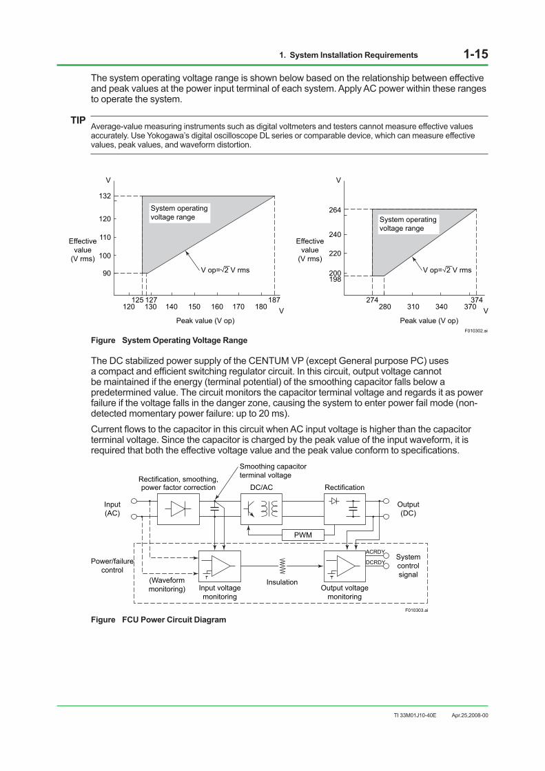
The system operating voltage range is shown below based on the relationship between effective and peak values at the power input terminal of each system. Apply AC power within these ranges to operate the system.
TIPAverage-value measuring instruments such as digital voltmeters and testers cannot measure effective values accurately. Use Yokogawa’s digital oscilloscope DL series or comparable device, which can measure effective values, peak values, and waveform distortion.
120125 127
90
100
110
120
132
130 140 150 160 170187
Peak value (V op)V
V
Effectivevalue
(V rms)
Effectivevalue
(V rms)
System operating voltage range
F010302.ai
274
200198
220
240
264
280 310 340 370374
Peak value (V op)V
V
180
System operating voltage range
V op= 2 V rms V op= 2 V rms
Figure System Operating Voltage Range
The DC stabilized power supply of the CENTUM VP (except General purpose PC) uses a compact and efficient switching regulator circuit. In this circuit, output voltage cannot be maintained if the energy (terminal potential) of the smoothing capacitor falls below a predetermined value. The circuit monitors the capacitor terminal voltage and regards it as power failure if the voltage falls in the danger zone, causing the system to enter power fail mode (non-detected momentary power failure: up to 20 ms). Current flows to the capacitor in this circuit when AC input voltage is higher than the capacitor terminal voltage. Since the capacitor is charged by the peak value of the input waveform, it is required that both the effective voltage value and the peak value conform to specifications.
F010303.ai
Rectification, smoothing,power factor correction
Input voltagemonitoring
DC/AC Rectification
Output voltagemonitoring
PWM
ACRDY
DCRDY
Input(AC)
Power/failurecontrol
Output(DC)
Systemcontrolsignal
(Waveformmonitoring)
Insulation
Smoothing capacitorterminal voltage
Figure FCU Power Circuit Diagram
Apr.25,2008-00

1. System Installation Requirements 1-16
TI 33M01J10-40E
Selecting a Power SystemThe CENTUM VP system requires a power supply that satisfies power requirements in accordance with EMC regulations. It is recommended that an external power supply unit is employed in order to prevent disruptions due to momentary or extended power failure, line noise, or lightening surges, as well as to suppress harmonic current from various devices. For selection of the power supply unit, consult with a power unit manufacturer taking the following points into consideration.
Source Output CapacityTake the following items into consideration when consulting with a power unit manufacturer to determine the output capacity.
Power consumption: Both volt-ampere and watt data should be studied (refer to Chapter 4).Device crest factor: Ratio of the peak value to the effective value of the device input current.Device in-rush current: See Chapter 4 Table “In-rush Current.” The method of turning on the power should also be studied.Backup ready time after failure: Time period required to backup the devices when power fails.Reserve capacity: An extra power capacity should be determined as reserve to meet any device additions.
Crest factorThe crest factor is the ratio of the peak value to the effective value of the device input current.
F010304.ai
Input voltage waveform
Approx. 5 msInput current waveform
Effective value
Peak value
Effective valuePeak value
Crest factor =
Figure Input Voltage and Input Current Waveforms
Apr.25,2008-00
1. System Installation Requirements 1-17
TI 33M01J10-40E
Crest factor = Peak value of device input current/Effective value of device input current The crest factor must be considered for the input current supplied to every device connected to the system when estimating the power output capacity in selecting the power unit. Approximate device crest factors should be as follows:100-120 V supply voltage: Crest factor About 3.220-240 V supply voltage: Crest factor About 6.
Common Method to Determine Power Unit CapacityThe following shows the commonly used method used to determine the power unit capacity taking the crest factor into consideration - the final determination should be made in consultation with a power unit manufacturer:
• If the specification of power unit crest factor (the peak current value allowable for the effective current value) is larger than the above device crest factor, the power unit can be used for up to full rated capacity. However, in-rush current, backup time, reserve capacity, etc., must be separately taken into consideration.
• If the power unit crest factor is smaller than the device crest factor, the power unit capacity needs to be calculated in the expression shown below. In-rush current, backup time, reserve capacity, etc., must be separately taken into consideration.
Power unit output capacity = Total device power consumption x Capacity coefficient
Capacity coefficient = Device crest factor / Power unit crest factor specification
In-Rush CurrentWhen the equipment is turned on, a large in-rush current flows as the capacitor is instantaneously charged and the transformer is excited. When any equipment is turned on or shut down, this should not cause any voltage fluctuation that could adversely affect other equipment. Do not turn on all equipment at the same time. Start equipment one by one. Power may be switched to backup or AC line power if in-rush current activates the overload protection circuit on power-up. After such an overload, select an uninterruptible power unit, with automatic-recovery.
Suppressing Harmonic CurrentIn order to suppress harmonic current supplied to a low-voltage distribution system, it is necessary to install a power unit or an active harmonic suppressor, such as indicated below, between a device and the distribution system:
• Power unit equipped with the harmonic suppression function (a high power-factor inverter-type uninterruptible power unit, etc.)
• Active harmonic suppressor
In Europe, a power unit should be selected so that harmonic current emissions are within the limits specified by EMC regulations. The capacity of the harmonic suppression unit should be determined in consultation with a power unit manufacturer in the same manner as the selection of power unit’s output capacity previously discussed.
Apr.25,2008-00

1. System Installation Requirements 1-18
TI 33M01J10-40E
CablingObserve the following when cabling the power unit to the CENTUM VP system equipment:
• Protect signal cables from induced noise.
• Protect signal cables from induction from high-voltage power lines.
• Separate the CENTUM VP system power supply from other equipment power supplies-use a separate power distribution board.
• Provide a dedicated breaker for each power supply. Install breakers and devices they control they control in the same room.
• As far as possible install power supply cables and high-voltage power lines in metallic conduits.
• Use shielded cables if metallic conduits cannot be provided.
Apr.25,2008-00
1. System Installation Requirements 1-19
TI 33M01J10-40E
1.4 GroundingTo avoid shock hazards and minimize the effects of external noise, the installed devices must be grounded with a ground resistance of 100 ohms or less and a grounding bus of 22 mm2 or thicker. Do not ground the CENTUM VP system to the same ground as devices of other systems. In the CENTUM VP field control station (FCS), expansion I/O cabinets, and console type human interface station (console type HIS), grounding bars are provided. When the power supply is plug-in rather than hard-wired, use the power cable for grounding.
The reference-grounding bar and the concatenation grounding bus, which is for potential equalization defined with the relevant standards, or grounding including meshed earth described in IEC 60364, IEC 62305 and IEC 61000-5-2 can be selected to satisfy the specification of 100 ohms or less.
The term “independent grounding” means to avoid any impedance caused by grounding the system to the same ground as devices of other systems, and it does not necessarily forbid equipotential bonding, nor require to install a grounding electrode independently.
Apr.25,2008-00
1. System Installation Requirements 1-20
TI 33M01J10-40E
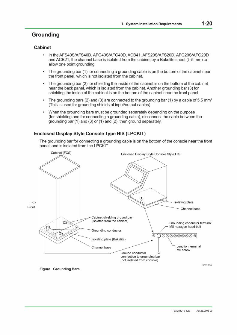
Grounding
Cabinet• In the AFS40S/AFS40D, AFG40S/AFG40D, ACB41, AFS20S/AFS20D, AFG20S/AFG20D
and ACB21, the channel base is isolated from the cabinet by a Bakelite sheet (t=5 mm) to allow one point grounding.
• The grounding bar (1) for connecting a grounding cable is on the bottom of the cabinet near the front panel, which is not isolated from the cabinet.
• The grounding bar (2) for shielding the inside of the cabinet is on the bottom of the cabinet near the back panel, which is isolated from the cabinet. Another grounding bar (3) for shielding the inside of the cabinet is on the bottom of the cabinet near the front panel.
• The grounding bars (2) and (3) are connected to the grounding bar (1) by a cable of 5.5 mm2 (This is used for grounding shields of input/output cables).
• When the grounding bars must be grounded separately depending on the purpose (for shielding and for connecting a grounding cable), disconnect the cable between the grounding bar (1) and (3) or (1) and (2), then ground separately.
Enclosed Display Style Console Type HIS (LPCKIT)The grounding bar for connecting a grounding cable is on the bottom of the console near the front panel, and is isolated from the LPCKIT.
F010401.ai
Cabinet (FCS)
Front
Grounding conductor terminal:M8 hexagon head bolt
Isolating plate
Channel base
Junction terminal:M5 screw
Channel base
Isolating plate (Bakelite)
Grounding conductor
Cabinet shielding ground bar(isolated from the cabinet)
Ground conductorconnection to grounding bar(not isolated from console)
Enclosed Display Style Console Style HIS
(1)(2)
(3)
(1)
Figure Grounding Bars
Apr.25,2008-00

1. System Installation Requirements 1-21
TI 33M01J10-40E
Open Display Style Console Type HIS (YPCKIT)The grounding bar for connecting a grounding cable is on the bottom of the console near the front panel, and is isolated from the HIS.
Example Dual Stacked LCD
Ground wiring bar(not isolated from console)
Isolating plate
Channel base
Ground terminal:M8 hexagon head bolt
Junction Terminal: M5 screw
F010409.ai
Figure Open Display Style Console Kit Grounding Bar
Apr.25,2008-00
1. System Installation Requirements 1-22
TI 33M01J10-40E
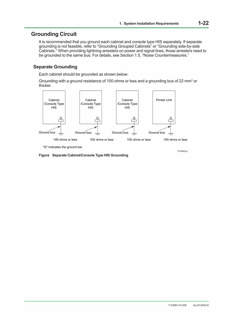
Grounding CircuitIt is recommended that you ground each cabinet and console type HIS separately. If separate grounding is not feasible, refer to “Grounding Grouped Cabinets” or “Grounding side-by-side Cabinets.” When providing lightning arresters on power and signal lines, those arresters need to be grounded to the same bus. For details, see Section 1.5, “Noise Countermeasures.”
Separate GroundingEach cabinet should be grounded as shown below:Grounding with a ground resistance of 100 ohms or less and a grounding bus of 22 mm2 or thicker.
F010402.ai
G
Cabinet/Console Type
HIS
G
Cabinet/Console Type
HIS
G
Cabinet/Console Type
HIS
100 ohms or less
Ground bus
100 ohms or less
Ground bus
100 ohms or less
Ground bus
"G" indicates the ground bar.
G
Printer Unit
100 ohms or less
Ground bus
Figure Separate Cabinet/Console Type HIS Grounding
Apr.25,2008-00
1. System Installation Requirements 1-23
TI 33M01J10-40E
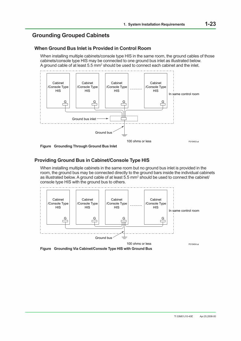
Grounding Grouped Cabinets
When Ground Bus Inlet is Provided in Control RoomWhen installing multiple cabinets/console type HIS in the same room, the ground cables of those cabinets/console type HIS may be connected to one ground bus inlet as illustrated below. A ground cable of at least 5.5 mm2 should be used to connect each cabinet and the inlet.
G
Cabinet/Console Type
HIS
G
Cabinet/Console Type
HIS
G
Cabinet/Console Type
HIS
G
Cabinet/Console Type
HISIn same control room
100 ohms or less
Ground bus
Ground bus inlet
F010403.ai
Figure Grounding Through Ground Bus Inlet
Providing Ground Bus in Cabinet/Console Type HISWhen installing multiple cabinets in the same room but no ground bus inlet is provided in the room, the ground bus may be connected directly to the ground bars inside the individual cabinets as illustrated below. A ground cable of at least 5.5 mm2 should be used to connect the cabinet/console type HIS with the ground bus to others.
G
Cabinet/Console Type
HIS
G
Cabinet/Console Type
HIS
G
Cabinet/Console Type
HIS
G
Cabinet/Console Type
HISIn same control room
100 ohms or less
Ground bus
F010404.ai
Figure Grounding Via Cabinet/Console Type HIS with Ground Bus
Apr.25,2008-00

1. System Installation Requirements 1-24
TI 33M01J10-40E
Grounding with Other SystemAs far as possible, avoid mounting CENTUM VP in contact with an other system. If this cannot be avoided, either provide insulating sheets and separate grounding or insulate the other system from the floor, and ground both CENTUM VP and the other system via a common ground bar.
IMPORTANT Do not install the following systems side-by-side with CENTUM VP:
• Systems using power supply voltages over 300 V AC.
• Systems with current consumption over 50 A.
• System containing high frequency sources.
G
Cabinet
G
100 ohms or lessF010405.ai
Ground bus
Insulating sheet
Insulating sheet
CENTUM VP Other system Insulating sheet material: PVC or PL-PEV BakeliteThickness: 5-10 mm
Figure Grounding Using Insulating Sheets
G
Cabinet
G
100 ohms or less F010406.ai
Ground bus
Insulating sheet
CENTUM VP Other system
Figure Grounding by Insulation from Floor
Apr.25,2008-00
1. System Installation Requirements 1-25
TI 33M01J10-40E
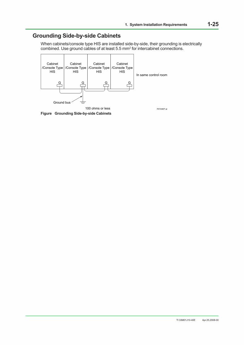
Grounding Side-by-side CabinetsWhen cabinets/console type HIS are installed side-by-side, their grounding is electrically combined. Use ground cables of at least 5.5 mm2 for intercabinet connections.
G
Cabinet/Console Type
HIS
G
Cabinet/Console Type
HIS
G
Cabinet/Console Type
HIS
G
Cabinet/Console Type
HISIn same control room
100 ohms or less
Ground bus
F010407.ai
Figure Grounding Side-by-side Cabinets
Apr.25,2008-00

1. System Installation Requirements 1-26
TI 33M01J10-40E
1.5 Noise CountermeasuresNoise may be induced by electromagnetic induction, electrostatic induction, or from radio waves, lightning, inductive loads, static electricity and ground potential differences. It can be picked up by power, signal and ground cables, and devices. With computerized control systems, noise-induced errors in A/D conversion or in an instruction word may lead to malfunction.
To prevent noise and electrostatic buildup, take the measures described in this section in deciding cable type, cable routing, and grounding.
Apr.25,2008-00
1. System Installation Requirements 1-27
TI 33M01J10-40E
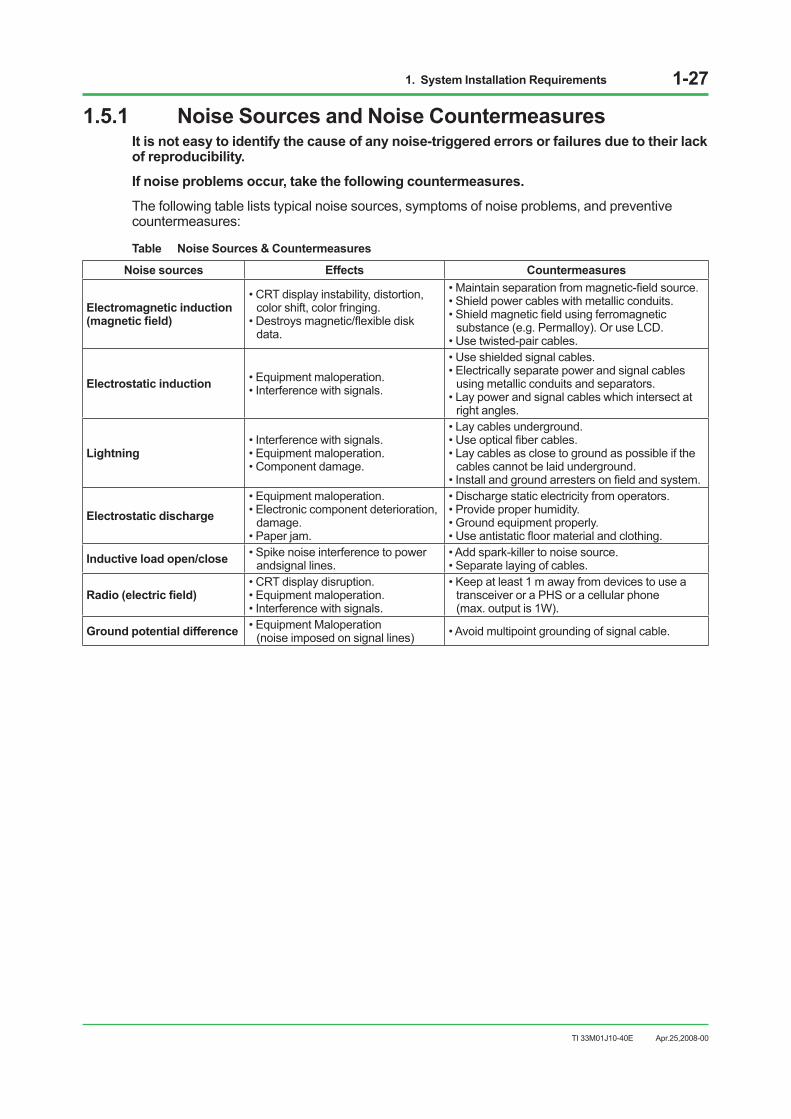
1.5.1 Noise Sources and Noise CountermeasuresIt is not easy to identify the cause of any noise-triggered errors or failures due to their lack of reproducibility.
If noise problems occur, take the following countermeasures.
The following table lists typical noise sources, symptoms of noise problems, and preventive countermeasures:
Table Noise Sources & Countermeasures
Noise sources Effects Countermeasures
Electromagnetic induction (magnetic field)
• CRT display instability, distortion, color shift, color fringing.
• Destroys magnetic/flexible disk data.
• Maintain separation from magnetic-field source. • Shield power cables with metallic conduits. • Shield magnetic field using ferromagnetic
substance (e.g. Permalloy). Or use LCD. • Use twisted-pair cables.
Electrostatic induction • Equipment maloperation. • Interference with signals.
• Use shielded signal cables. • Electrically separate power and signal cables
using metallic conduits and separators. • Lay power and signal cables which intersect at
right angles.
Lightning • Interference with signals. • Equipment maloperation. • Component damage.
• Lay cables underground. • Use optical fiber cables. • Lay cables as close to ground as possible if the
cables cannot be laid underground. • Install and ground arresters on field and system.
Electrostatic discharge • Equipment maloperation. • Electronic component deterioration,
damage. • Paper jam.
• Discharge static electricity from operators. • Provide proper humidity. • Ground equipment properly. • Use antistatic floor material and clothing.
Inductive load open/close • Spike noise interference to power andsignal lines.
• Add spark-killer to noise source. • Separate laying of cables.
Radio (electric field) • CRT display disruption. • Equipment maloperation. • Interference with signals.
• Keep at least 1 m away from devices to use a transceiver or a PHS or a cellular phone (max. output is 1W).
Ground potential difference • Equipment Maloperation (noise imposed on signal lines) • Avoid multipoint grounding of signal cable.
Apr.25,2008-00
1. System Installation Requirements 1-28
TI 33M01J10-40E
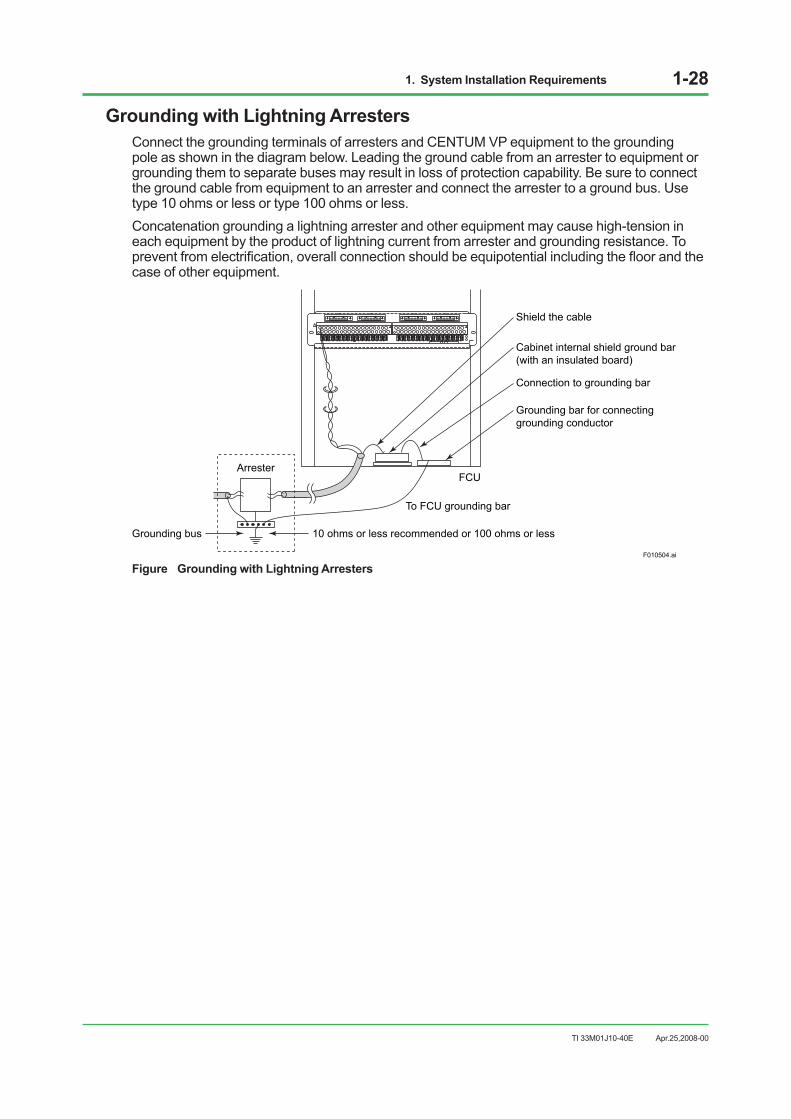
Grounding with Lightning ArrestersConnect the grounding terminals of arresters and CENTUM VP equipment to the grounding pole as shown in the diagram below. Leading the ground cable from an arrester to equipment or grounding them to separate buses may result in loss of protection capability. Be sure to connect the ground cable from equipment to an arrester and connect the arrester to a ground bus. Use type 10 ohms or less or type 100 ohms or less.Concatenation grounding a lightning arrester and other equipment may cause high-tension in each equipment by the product of lightning current from arrester and grounding resistance. To prevent from electrification, overall connection should be equipotential including the floor and the case of other equipment.
F010504.ai
ArresterFCU
10 ohms or less recommended or 100 ohms or lessGrounding bus
To FCU grounding bar
Grounding bar for connectinggrounding conductor
Connection to grounding bar
Shield the cable
Cabinet internal shield ground bar(with an insulated board)
Figure Grounding with Lightning Arresters
Apr.25,2008-00

1. System Installation Requirements 1-29
TI 33M01J10-40E
Examples of ArresterThe following shows how to install an arrester as a countermeasure against lightning-induced noise :
GND
I/Omodule
AR ARI/O
module
GND
System sideField wiring
+
-
AR AR
System sideField wiring
A
BB
I/Omodule
GND
AR
System sideField wiring
+
-
AR
Field wiring
: Induced lightning strike point AR: Arrester
F010501.ai
2-wire transmitter/analyzer
Resistance temperature detector
Thermocouple
Power supply
GND
System
2-wiretransmitter
Figure Examples of Arrester Installation
Examples of Spark-killer InstallationThe following shows how to install a spark-killer as a countermeasure against inductive load-caused noise:
Relay contact
Power supply
F010502.ai
Example R: 120 ohmsC: 0.1 to 0.3 μF
Example R: 120 ohmsC: 0.1 μF
Spark killer CENTUM VP100 V ACFluorescent
lamp or fan
The spark killer prevents noise-caused equipment failure when a fluorescent lamp or fan is turned on or off.
The diode protects the output transistorfrom noise occurring during on-to-offtransitions of the relay.
The spark killer protects the output relay contact. Diode Controller
control signal
Sparkkiller
24 V DC
Tr
Relay
Figure Examples of Spark-killer Installation
Apr.25,2008-00
1. System Installation Requirements 1-30
TI 33M01J10-40E
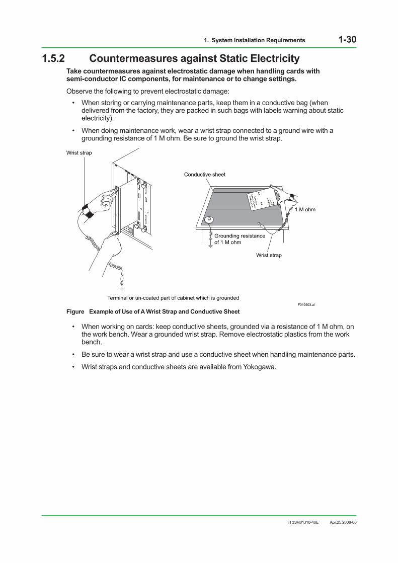
1.5.2 Countermeasures against Static ElectricityTake countermeasures against electrostatic damage when handling cards with semi-conductor IC components, for maintenance or to change settings.
Observe the following to prevent electrostatic damage:• When storing or carrying maintenance parts, keep them in a conductive bag (when
delivered from the factory, they are packed in such bags with labels warning about static electricity).
• When doing maintenance work, wear a wrist strap connected to a ground wire with a grounding resistance of 1 M ohm. Be sure to ground the wrist strap.
F010503.ai
Wrist strap
Terminal or un-coated part of cabinet which is grounded
1 M ohm
Conductive sheet
Grounding resistanceof 1 M ohm
Wrist strap
Figure Example of Use of A Wrist Strap and Conductive Sheet
• When working on cards: keep conductive sheets, grounded via a resistance of 1 M ohm, on the work bench. Wear a grounded wrist strap. Remove electrostatic plastics from the work bench.
• Be sure to wear a wrist strap and use a conductive sheet when handling maintenance parts.
• Wrist straps and conductive sheets are available from Yokogawa.
Apr.25,2008-00
1. System Installation Requirements 1-31
TI 33M01J10-40E
1.6 Cabling RequirementsThe following requirements must be fulfilled when laying power and signal cables (These are shielded cables unless specified).
Any signal cable used for high-voltage, high-frequency signals (inductive load ON/ OFF) must be separated from other signal cables.
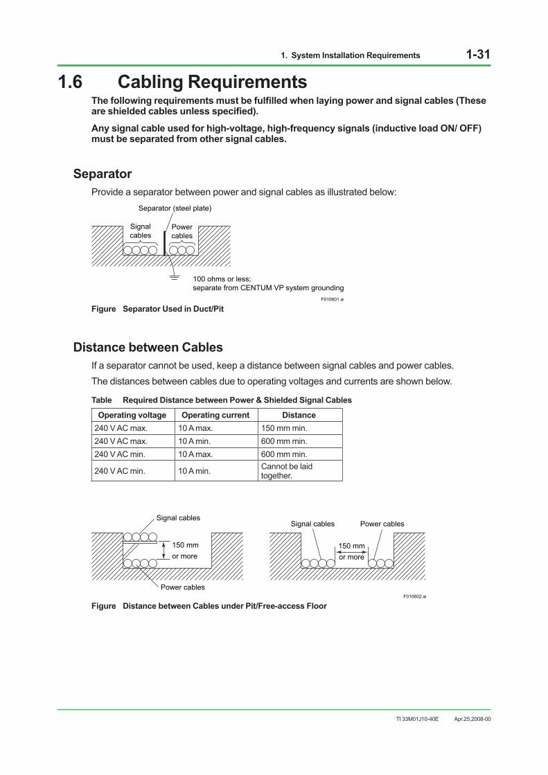
SeparatorProvide a separator between power and signal cables as illustrated below:
Signalcables
Powercables
Separator (steel plate)
100 ohms or less; separate from CENTUM VP system grounding
F010601.ai
Figure Separator Used in Duct/Pit
Distance between CablesIf a separator cannot be used, keep a distance between signal cables and power cables.The distances between cables due to operating voltages and currents are shown below.
Table Required Distance between Power & Shielded Signal Cables
Operating voltage Operating current Distance 240 V AC max. 10 A max. 150 mm min. 240 V AC max. 10 A min. 600 mm min. 240 V AC min. 10 A max. 600 mm min.
240 V AC min. 10 A min. Cannot be laid together.
Power cablesF010602.ai
150 mm or more
Signal cablesSignal cables Power cables
150 mmor more
Figure Distance between Cables under Pit/Free-access Floor
Apr.25,2008-00

1. System Installation Requirements 1-32
TI 33M01J10-40E
Intersecting CablesWith unshielded power cables, place a grounded steel plate with a thickness of at least 1.6 mm over the cables where they intersect with signal cables.
Signal cables
Steel plate (1.6 mm or thicker, grounded)
Unshielded power cablesF010603.ai
Figure Intersecting Cables under Pit/Free-access Floor
Ambient TemperatureThe ambient temperature where signal and bus cables are laid must be within the range –10 to 60 °C.When using ER bus node units (ANR10S/ANR10D) to conform to the temperature specification, the ambient temperature where the cables are laid must be within the range –20 to 70 °C.
Measures against EMIAs a rule, avoid laying the cables on the floor. However, lay them on the floor when there are no ducts and no pits. In that case, it is required to cover them with shield plates or take other measures to suit the EMC Directive.
Apr.25,2008-00

1. System Installation Requirements 1-33
TI 33M01J10-40E
1.7 Corrosive-gas Environment CompatibilityThe CENTUM VP system employs ER bus node units and FIO input/output modules which meet the ANSI/ISA G3 environment requirements and are compatible with the corrosive gas-susceptible environment.
G3 Environment-compatible ProductsTable G3 Environment-compatible Products (1/2)
No. Product Model Description
1 Field control unit AFF50 -1 Compact Field control unit (for FIO)
2 Node unit ANR10-3 ER bus node unit (19-inch Rack Mount type)
3 Analog I/O modules
AAI141-3 Analog input module (4 to 20 mA, 16-channel, non-isolated) AAV141-3 Analog input module (1 to 5 V, 16-channel, non-isolated) AAV142-3 Analog input module (–10 to +10 V, 16-channel, non-isolated)
AAI841-3 Analog I/O module (4 to 20 mA input, 4 to 20 mA output, 8-channel/8-channel, non-isolated)
AAB841-3 Analog I/O module (1 to 5 V input, 4 to 20 mA output, 8-channel/8-channel, non-isolated)
AAV542-3 Analog output module (–10 to +10 V, 16-channel, non-isolated)
AAP149-1 Pulse input module for compatible PM1 (16-channel, pulse count, 0 to 6 kHz, non-isolated)
AAP849-1 Pulse input/Analog output module for compatible PAC (Pulse count input, 4 to 20mA output, 8-channel/8-channel, non-isolated)
AAI143-3 Analog Input Module (4 to 20 mA, 16-Channel, Isolated) AAI543-3 Analog Output Module (4 to 20 mA, 16-Channel, Isolated) AAV141-3 Analog input module (–10 to +10 V, 16-channel, isolated) AAV544-3 Analog output module (–10 to +10 V, 16-channel, isolated) AAT141-3 Thermocouple/mV input module (16-channel, isolated) AAR181-3 Resistance temperature detector input module (12-channel, isolated) AAI135-3 Analog input module (4 to 20 mA, 8-channel, isolated channels) AAI835-3 Analog I/O module (4 to 20 mA, 4-channel/4-channel, isolated channels) AAT145-3 Thermocouple/mV input module (16-channel, isolated channels)
AAR145-3 Resistance temperature detector/potentiometer input module (16-channel, isolated channels)
AAP135-3 Pulse input module (8-channel, 0 to 10 kHz, isolated channels)
Apr.25,2008-00

1. System Installation Requirements 1-34
TI 33M01J10-40E
Table G3 Environment-compatible Products (2/2)
No. Product Model Description
4 Digital I/O modules
ADV151-3 Digital input module (32-channel, 24 V DC, isolated)
ADV141-3 Digital input module (16-channel, 100 to 120 V AC, isolated)
ADV142-3 Digital input module (16-channel, 220 to 240 V AC, isolated)
ADV551-3 Digital output module (32-channel, 24 V DC, isolated)
ADR541-3 Relay output module (16-channel, 24 to 110 V DC/100 to 240 V AC, isolated)
ADV157-1 Digital input module (32-channel, 24 V DC, for pressure clamp terminals, isolated)
ADV557-1 Digital output module (32-channel, 24 V DC, for pressure clamp terminals, isolated)
ADV161-1 Digital input module (64-channel, 24 V DC, isolated)
ADV561-1 Digital output module (64-channel, isolated)
ADV859-1 Digital I/O module for compatible ST2 (16-channel input/16-channel output, isolated channels)
ADV159-1 Digital input module for compatible ST3 (32-channel, isolated channels)
ADV559-1 Digital output module for compatible ST4 (32-channel, isolated channels)
ADV869-1 Digital I/O module for compatible ST5 (32-channel input/32-channel output, isolated, common minus side every 16-channel)
ADV169-1 Digital input module for compatible ST6 (64-channel, isolated, common minus side every 16-channel)
ADV569-1 Digital output module for compatible ST7 (64-channel, isolated, common minus side every 16-channel)
5
ALR111-1 RS-232C Communication Module (2-Port, 1200 bps to 115.2 kbps)
ALR121-1 RS-422/RS-485 Communication Module (2-Port, 1200 bps to 115.2 kbps)
ALE111-1 Ethernet Communication Module (1-Port, 10 Mbps)
ALF111-1 Foundation Fieldbus (FF-H1) Communication Module (4-Port, 31.25 kbps)
ALP111-1 PROFIBUS-DPV1 Communication Module (1-Port, 9600 bps to 12 Mbps)
6AGS813-1 Servo Module (Isolated)
AGP813-1 High Speed Protection Module (Isolated)
Apr.25,2008-00

1. System Installation Requirements 1-35
TI 33M01J10-40E
Outline of G3 Environment CompatibilityThe classification of the environment in which the process control equipment is installed is determined by the ANSI/ISA S71.04 “Environmental Conditions for Process Control Systems” standard. The environment having an atmosphere which contains steams and mists (liquids, coded L), dusts (solids, coded S), or corrosive gases (gases, coded G) is classified into four categories according the levels of these substances determined.
The four categories of the corrosive gas environment are defined as follows:G1 (mild): A well-controlled environment in which corrosive gas is not the major cause adversely affecting the reliability of plant equipment. The corrosion level on the copper test piece is below 0.03 µm (see note below).G2 (moderate): An environment in which corrosive gas can be detected and it could be determined that the gas is the major cause adversely affecting the reliability of plant equipment. The corrosion level on the copper test piece is below 0.1 µm (see note below).G3 (harsh): An environment in which corrosive gas is frequently generated to cause corrosion and that it is necessary to provide special measures or employ specially designed or packaged plant equipment. The corrosion level on the copper test piece is below 0.2 µm (see note below).GX (severe): A corrosive gas-polluted environment that demands special protective chassis for the plant equipment, specifications of which should be seriously determined by the user and a power unit manufacturer. The corrosion level on the copper test piece is 0.2 µm or more (see note below).Note: Copper test pieces are used to determine the level of corrosion for the classification of the plant environment. The test piece is an
oxygen-free copper sheet, which is 15 cm2 in area, 0.635 mm in thickness, 1/2 to 3/4 H in hardness. The test piece is placed in the plant site for one month and checked for any change before and after the test to determine the degree of corrosion (see table below). If the test period is shorter than one month, the result is calculated to obtain equivalent data using a expression defined by the standard.
Table Classification of Corrosive-gas Corrosion Levels
Environment category G1 Mild
G2 Moderate
G3 arsh
GX Severe
Copper corrosion level < 300 (< 0.03)
< 1000 (< 0.1)
< 2000 (< 0.2)
≥ 2000 (≥ 0.2)
[Å] ( [μm] )
Group A H2S < 3 < 10 < 50 ≥ 50 [mm3/m3]
SO2, SO3 < 10 < 100 < 300 ≥ 300
Cl2 < 1 < 2 < 10 ≥ 10
NOx < 50 < 125 < 1250 ≥ 1250
Group B HF < 1 < 2 < 10 ≥ 10
NH3 < 500 < 10000 < 25000 ≥ 25000
O3 < 2 < 25 < 100 ≥ 100
Note: The gas density data indicated in the table are for reference only, with the relative humidity of 50 %RH or less. The category goes up one rank higher every time the humidity increases 10 % exceeding the 50 %RH or over 6 % per hour.
The Group-A gases shown in the table may coexist and cause inter-reaction. Inter-reaction factors are not known for the Group-B gases.
Apr.25,2008-00

2. Transportation, Storage and Installation 2-1
TI 33M01J10-40E
2. Transportation, Storage and Installation
This chapter describes the precautions in transporting, storing, and installing the CENTUM VP system equipment.
SEE ALSO See “Section 1.2 Control Room Environment” for the environmental requirement for each piece of equipment.
Apr.25,2008-00

2. Transportation, Storage and Installation 2-2
TI 33M01J10-40E
2.1 Precautions for TransportationThis section describes the precautions required to prevent accidents and damage when transporting CENTUM VP system equipment. These precautions apply when the equipment is contained in our original packing.
Transportation
SEE ALSO See “Table Equipment Installation Specifications” in Section 1.2 Control Room Environment for ambient
temperature, humidity, vibration and impact.
Loading• Do not load crates on top of others or turn them on their sides.
• Keep all crates upright.
• Secure loaded crates using ropes, and cover them completely with waterproof coverings.
• Do not load crates outdoors when it is raining.
Don’t Stack OutdoorsBe sure to store cargoes inside a warehouse if they must be stored for some time.
TransportationCargoes contain precision instruments. Select a company specializing in the transportation of computers and precision instruments.Keep all products upright during air transport, freightage, or truck transport. When transporting by track, drive at low speed to avoid vibration and impact. Also, slow down to the limit on a bad road.
Transportation for LPCKIT, YPCKITWhen transporting these kits, pack its personal computer (main body) and UPS (if installed) separately from others. For YPCKIT, LCD must be packed separately as well.
OthersDo not transport equipment through areas where there may be corrosive gas, intense electric or magnetic fields.
Apr.25,2008-00

2. Transportation, Storage and Installation 2-3
TI 33M01J10-40E
UnloadingPrepare special equipment for unloading. Avoid unloading outdoor in case of rain.
Location for UnloadingTo select a location for safe unloading, check that:
• There is ample space for crane and forklift maneuvering.
• Ground is solid.
• The handrails of scaffold can be removed.
• There is enough working space for unpacking (at least 2500 mm by 4000 mm). Provide a platform if necessary.
• There is a height of at least 3000 mm under the roof.
• Outdoor-indoor temperature difference should be less than 10 °C to avoid condensation.
Keep UprightKeep crates upright when unloading.
Avoid Physical ShockAvoid physical shock. Be careful not to lose balance or swing when lifting or placing cargoes on the ground or platform. Also check scaffold strength.
CAUTION• When lifting Hardware with a crane, do not unpack it, but attach lifting bolts or wire ropes to
the baseboard positions shown to lift it. Keep the distance between the crane hook and the cargo to be lifted at a minimum.
• If it is difficult to do this, tie four belts together at a point close to the cargo to keep it from falling.
• Unpacked items are more likely to lose their balance and fall.
Apr.25,2008-00
LPCKIT and YPCKIT with CraneThere are no eye bolts on top of LPCKIT/YPCKIT for lifting it. When lifting a LPCKIT or a YPCKIT with crane, use a baseboard with lifting bolts on front and rear, or use wire ropes (see figure). Labels indicating the center of gravity are attached at the both sides of the package.
F020102.ai
Center of gravity label
Baseboard
Figure Lifting LPCKIT/YPCKIT with a Crane
2. Transportation, Storage and Installation 2-4
TI 33M01J10-40E
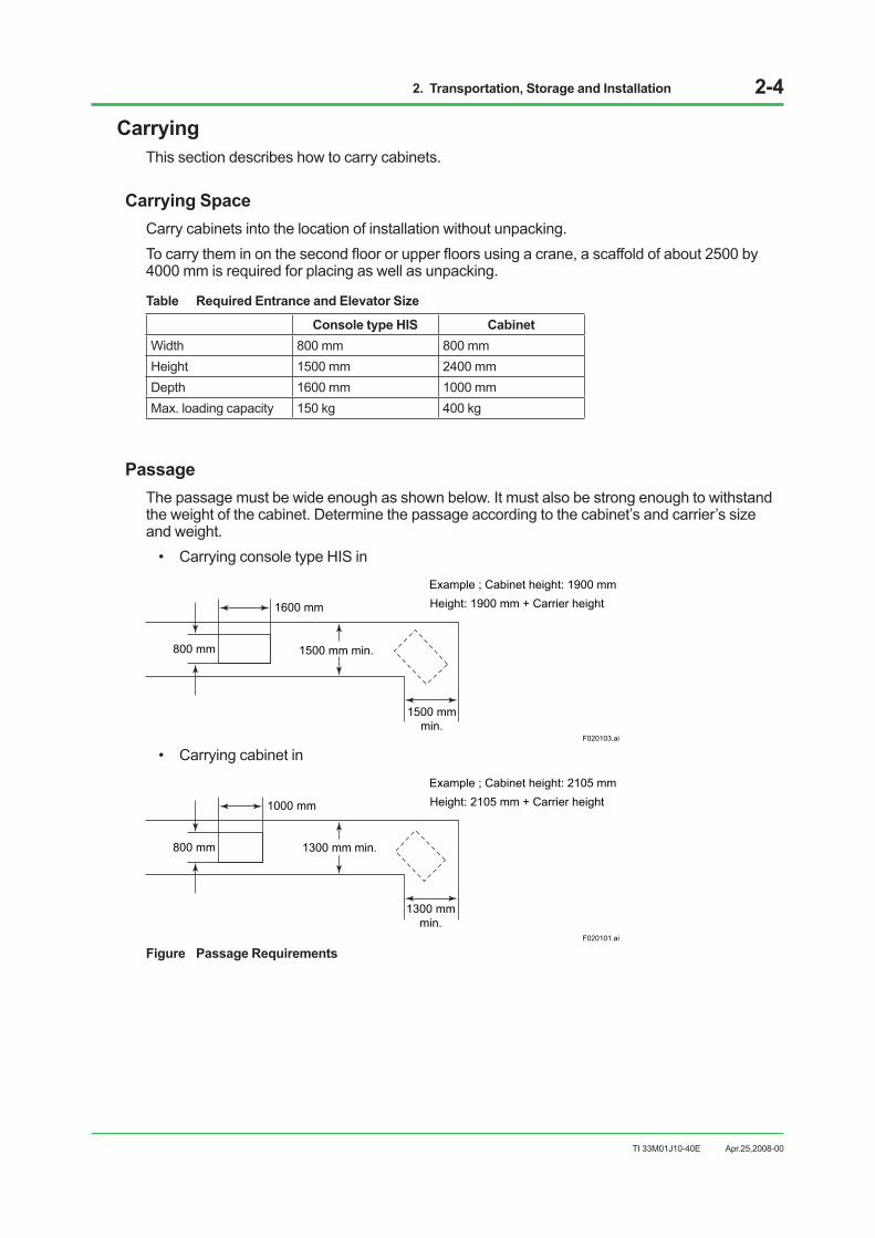
CarryingThis section describes how to carry cabinets.
Carrying SpaceCarry cabinets into the location of installation without unpacking. To carry them in on the second floor or upper floors using a crane, a scaffold of about 2500 by 4000 mm is required for placing as well as unpacking.
Table Required Entrance and Elevator Size
Console type HIS Cabinet Width 800 mm 800 mm Height 1500 mm 2400 mm Depth 1600 mm 1000 mm Max. loading capacity 150 kg 400 kg
PassageThe passage must be wide enough as shown below. It must also be strong enough to withstand the weight of the cabinet. Determine the passage according to the cabinet’s and carrier’s size and weight.
• Carrying console type HIS in
1600 mm
800 mm 1500 mm min.
1500 mmmin.
F020103.ai
Height: 1900 mm + Carrier heightExample ; Cabinet height: 1900 mm
• Carrying cabinet in
1000 mm
800 mm
1300 mmmin.
Height: 2105 mm + Carrier height
F020101.ai
1300 mm min.
Example ; Cabinet height: 2105 mm
Figure Passage Requirements
Apr.25,2008-00

2. Transportation, Storage and Installation 2-5
TI 33M01J10-40E
Carrying when Headroom is LowThe cabinet should be carried upright. If this is impossible due to low headroom,
• Remove the side boards.
• Turn the cabinet’s right or left side (viewed from its front) down.
• Gently carry the cabinet with the side down.
• Turn the cabinet to its upright position as soon as the cabinet passes through a place with low headroom. Attach the side boards to the cabinet.
Using RollersThe cabinet should be carried in to or near the installation location without unpacking. Do not use rollers if possible. When using them, take the following precautions:
• Use wooden rollers which are long enough so that more than 200 mm remains outside of the cabinet on each side.
• Make sure that two or more rollers are always under the cabinet.
• Do not use a hammer to correct roller positions on the move.
Apr.25,2008-00

2. Transportation, Storage and Installation 2-6
TI 33M01J10-40E
2.2 UnpackingIn unpacking the received cargoes and equipment, inspect them according to inspection list below. It is recommended to unpack by Yokogawa engineers or in their presence.
Table Inspection List
Inspection Items Result Measures Required
Exterior
• Environment of unpacking location (temperature, humidity, dust)
Suitable Unsuitable If unsuitable, select proper location according to specified environmental requirements.
• Rapid temperature fluctuation (should be within ±10 °C/h)
No Yes If yes, do not unpack and wait until the fluctuation remains within ±10 °C/h.
• Damage to equipment exterior No Yes If damaged badly, inform Yokogawa. • Condensation or its trace on
equipment exterior. (*1)No Yes If yes, inform Yokogawa.
Interior
• Loose parts inside equipment. No Yes If yes, remove them and check the surrounding. • Damage to equipment interior. No Yes If damaged badly, inform Yokogawa. • Condensation or its trace on
equipment interior. (*1)No Yes If yes, inform Yokogawa.
*1: Condensation symptoms are as follows: • Dew patterns on PCBs. • Printed circuit copper trace is floating off the board. • Label characters on PCBs are smudged. • Connectors on PCBs are smudged. • Dew patterns or traces of droplets are found on cabinet panels.
IMPORTANT Condensation may cause a fatal system failure in the CENTUM VP system. Be sure to unpack the equipment indoor under the specified environmental conditions. Strictly observe the allowable temperature fluctuation range of ±10 °C/h. Do not bring the equipment into a heated room straight from the outside in winter. Our warranty does not cover any damage caused by condensation. Proper treatment may be able to minimize the damage caused by condensation, however. Contact Yokogawa in case of condensation.
IMPORTANT Be careful not to let the products fall when you handle them.When they are hit hard, the interior of them can be damaged, although there is no damage in the exterior.If you accidentally drop an product, stop using it immediately and report it to YOKOGAWA or YOKOGAWA’s service department.
Apr.25,2008-00
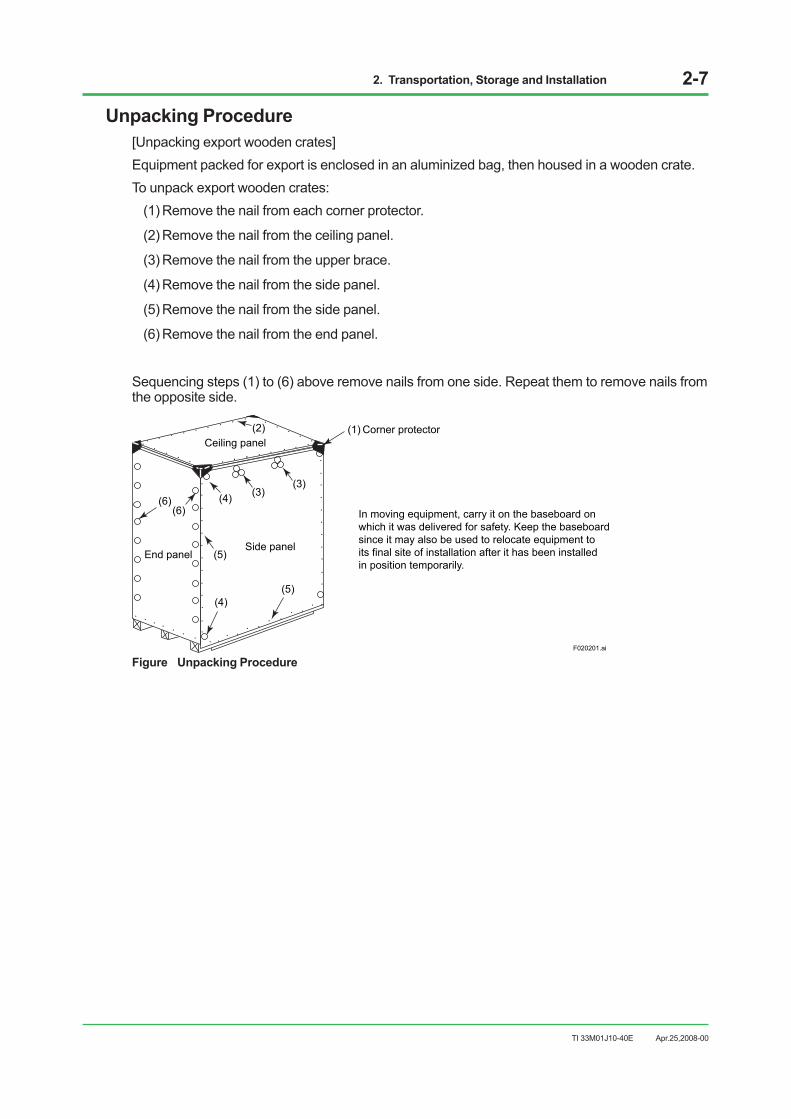
2. Transportation, Storage and Installation 2-7
TI 33M01J10-40E
Unpacking Procedure[Unpacking export wooden crates]Equipment packed for export is enclosed in an aluminized bag, then housed in a wooden crate. To unpack export wooden crates:
(1) Remove the nail from each corner protector.
(2) Remove the nail from the ceiling panel.
(3) Remove the nail from the upper brace.
(4) Remove the nail from the side panel.
(5) Remove the nail from the side panel.
(6) Remove the nail from the end panel.
Sequencing steps (1) to (6) above remove nails from one side. Repeat them to remove nails from the opposite side.
F020201.ai
(1)(2)
(3)(3)
(4)
(5)
(6)(6)
(4)(5)
Corner protector
Side panel
Ceiling panel
End panel
In moving equipment, carry it on the baseboard on which it was delivered for safety. Keep the baseboard since it may also be used to relocate equipment to its final site of installation after it has been installed in position temporarily.
Figure Unpacking Procedure
Apr.25,2008-00

2. Transportation, Storage and Installation 2-8
TI 33M01J10-40E
2.3 StorageThe delivery date should be determined in accordance with your installation schedule. Avoid storing products more than three months. If long-term storage cannot be avoided, consult us in advance because it is necessary to provide waterproofing, condensation prevention, and dustproofing measures as well as periodical inspections.
Storage ConditionStore products without unpacking. Be sure to confirm that the crate is not damaged. To store them after unpacking, be sure to take the precautions described below.
Location of StorageStore products in a warehouse or indoor facilities - never in an open-air location.
Storage Environment• Avoid direct sunlight.
• Prevent condensation.
• Do not store products where corrosive gas or salty air may be present.
SEE ALSO See “Section 1.2 Control Room Environment” for permissible temperature, humidity and temperature fluctuation
of storage area.
Storage of Packed Equipment• Place squared pieces of lumber with a height of 100 mm or higher on the floor. The lumber
should be long enough so that more than 100 mm remain outside of the crate on every side.
• Securely place unopened crates on the lumber platform.
• Do not stack crates in piles.
• Make sure to provide good air circulation in the storage area and periodically inspect the crates to keep them under proper conditions.
Storage of Unpacked EquipmentTo store unpacked products without power connection, follow the specified environmental requirements. If stored in a non-air-conditioned room, cover them with polyethylene or other sheets for protection against dust and moisture. For moisture-proofing, place a sufficient amount of Silica gel or other desiccating agent inside the covering and inspect replace from time to time.
Apr.25,2008-00

2. Transportation, Storage and Installation 2-9
TI 33M01J10-40E
2.4 Servicing AreaTake enough space around equipment for its operation and maintenance service. This servicing area is indicated for each equipment.
The servicing area should be considered in determining the size of installation location. When installing a number of equipment side by side, take the largest service-area between them if different dimensions are indicated for different side of equipment (see below).
800
800
800
600A
800
800
800
600A80080
080
0600A
800
800
800
600A 800
800
800
600A
F020400.ai
Placing another unit on this side
Good example
Unit: mm
Bad example
Figure Servicing Area when Installing Units Side-by-side
SEE ALSO For equipment servicing areas, refer to TI 33Q01J10-02E “External Dimensions.”
Apr.25,2008-00

2. Transportation, Storage and Installation 2-10
TI 33M01J10-40E
2.5 InstallationBefore installation, be sure that anchor bolts, pedestals, and cable holes are provided according to the customer’s system configuration plans. Check that the positions of holes on the floor fit the anchor bolt holes in the channel base of each piece of equipment.
Apr.25,2008-00

2. Transportation, Storage and Installation 2-11
TI 33M01J10-40E
2.5.1 Installation on FloorThe installation method varies with the type of the floor and building.
• After unpacked, be careful not to put any impact until it is fixed to the floor to prevent from tip-over.
• Install devices as specified in the plans. Check the position of front and back panels of the cabinet. Avoid physical shock. Never use hammers.
• The open display style console assembly YPCKIT (excluding option code FT) is provided with simple legs. When the YPCKIT is secured to the floor, remove and store the simple legs. Use them at the time of movement in the future.
• Fix each equipment to the floor. The explanation below shows how to fix devices on different types of floors.
Concrete FloorClamp the equipment to the floor using anchor bolts. It is recommended to use M12 bolts and 3,200 N•cm tightening torque.
Equipment
Anchor bolts
F020401.ai
Figure Using Anchor Bolts
Steel FloorClamp the equipment to the floor using clamp bolts. After cabling through the riser duct, fill the duct with rubber sponges and seal the top with putty.
Equipment
Steel floor
Clamp bolt
F020402.ai
Duct
Riser
Figure Using Clamp Bolts
Apr.25,2008-00

2. Transportation, Storage and Installation 2-12
TI 33M01J10-40E
“Free-access” FloorClamp the equipment to pedestals which are anchored to the base floor.
Equipment
Free-access floor
Base floor
Pedestal
F020403.ai
Figure Using Pedestal
In the “free-access” floor, make holes for riser cables to connect to each piece of equipment as follows:
• If one floor tile is removed, be sure to reinforce the opening with an angle frame for floor stability.
Free-access floor supports
Angle frame
F020404.ai
Figure Removing One Floor Tile
• Do not make a holes near the floor supports.
• Do not cut away more than 1/3 of a floor tile.
Apr.25,2008-00

2. Transportation, Storage and Installation 2-13
TI 33M01J10-40E
IMPORTANT If a number of neighboring floor tiles are removed, be sure to provide angle frames or pedestals for reinforcement.
F020405.ai
Bad example Good example
Figure Partially Cutting Floor Tile
Apr.25,2008-00

2. Transportation, Storage and Installation 2-14
TI 33M01J10-40E
Size of Cabling Holes in FloorFor ease of cabling, and for separating power cables from signal cables, it is recommended that you create holes in the floor for cabling that are the maximum size indicated in the floor plans.
SEE ALSO Refer to “External Dimensions” (TI 33Q01J10-02E) for the weight and dimensions.
If the specified maximum size hole cannot be provided due to the floor construction or pit dimensions, the size may be smaller within the range indicated in the plans. If you use the specified minimum size of hole, use flexible cables that can bend inside the channel base.
Cabinet
Sealed with putty
Cabling to frontCabling hole
Cabling to rear
F020406.ai
Distributionboard
Figure Cabling through Maximum Size Hole
Cabinet
Sealed with putty
Cabling to frontCabling hole
Cabling to rear
F020407.ai
Distributionboard
Figure Cabling through Minimum Size Hole
Apr.25,2008-00

2. Transportation, Storage and Installation 2-15
TI 33M01J10-40E
2.5.2 Installing the Console Type HIS Side-by-Side
LPCKITThe way to mount two or more console type HIS side by side, using bolts to join them, is described below. The same method is used to join universal consoles or CENTUM-XL cabinets with the same shape.
IMPORTANT The CENTUM-XL EOPS has a different-shaped operation keyboard than the console type HIS, so you can’t use the EOPS flat membrane keyboard if you want to mount EOPS and console type HIS side by side.
A B C D E F G
F020417.ai
Front door below desk
Channel base
Desk
LCD
Figure Example of side-by-side mounting of Console Type HIS
Installation(a) Level the floor surface on which cabinets are to be installed.
(b) To install two or more cabinets in a line, install the central one first (D in Figure), and next ones on both sides (C→B→A, E→F→G).
(c) With bottom plate (see Figure on next page) off, install the cabinet in position, making sure that the anchor bolt position and channel base hole align with each other.
(d) Tighten anchor bolt nut (a) (see Figure on next page) when the installation is complete. When linking many cabinets in a row, tighten the nuts only finger-tight first, fully tightening them when the cabinet interconnection is complete.
Apr.25,2008-00
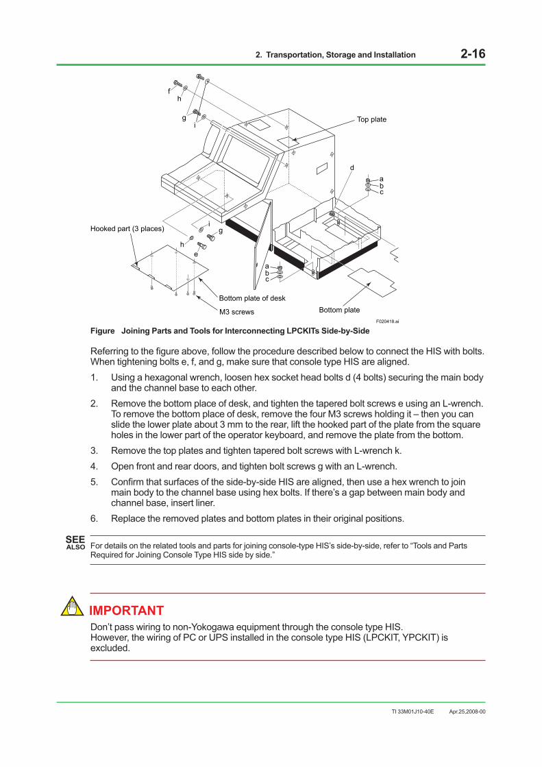
2. Transportation, Storage and Installation 2-16
TI 33M01J10-40E
abc
F020418.ai
Top plate
Bottom plateBottom plate of desk
M3 screws
Hooked part (3 places)
ad
bc
ig
eh
gi
fh
Figure Joining Parts and Tools for Interconnecting LPCKITs Side-by-Side
Referring to the figure above, follow the procedure described below to connect the HIS with bolts. When tightening bolts e, f, and g, make sure that console type HIS are aligned. 1. Using a hexagonal wrench, loosen hex socket head bolts d (4 bolts) securing the main body
and the channel base to each other. 2. Remove the bottom place of desk, and tighten the tapered bolt screws e using an L-wrench.
To remove the bottom place of desk, remove the four M3 screws holding it – then you can slide the lower plate about 3 mm to the rear, lift the hooked part of the plate from the square holes in the lower part of the operator keyboard, and remove the plate from the bottom.
3. Remove the top plates and tighten tapered bolt screws with L-wrench k. 4. Open front and rear doors, and tighten bolt screws g with an L-wrench. 5. Confirm that surfaces of the side-by-side HIS are aligned, then use a hex wrench to join
main body to the channel base using hex bolts. If there’s a gap between main body and channel base, insert liner.
6. Replace the removed plates and bottom plates in their original positions.
SEE ALSO For details on the related tools and parts for joining console-type HIS’s side-by-side, refer to “Tools and Parts
Required for Joining Console Type HIS side by side.”
IMPORTANT Don’t pass wiring to non-Yokogawa equipment through the console type HIS. However, the wiring of PC or UPS installed in the console type HIS (LPCKIT, YPCKIT) is excluded.
Apr.25,2008-00

2. Transportation, Storage and Installation 2-17
TI 33M01J10-40E
YPCKITThe way to mount two or more console type HIS side-by-side, using bolts to join them, is described below. The same method is used to join universal consoles or CENTUM-XL cabinets with the same shape.
IMPORTANT The CENTUM-XL EOPS has a different-shaped operation keyboard than the console type HIS, so you can’t use the EOPS flat membrane keyboard if you want to mount EOPS and console type HIS side-by-side.
F020422.ai
A B C
LCD
Desk
Front door below desk
Channel base
Figure Example of Side-by-side mounting of Console Type HIS
Installation(a) Level the floor surface on which HISs are to be installed.
(b) To install two or more HISs in a line, install the central one first (B in Figure), and next ones on both sides (C, A).
(c) With bottom plate (see Figure on next page) off, install the HIS in position, making sure that the anchor bolt position and channel base hole align with each other.
(d) Tighten anchor bolt nut (a) (see Figure on next page) when the installation is complete. When linking many HISs in a row, tighten the nuts only finger-tight first, fully tightening them when the HIS interconnection is complete.
Apr.25,2008-00

2. Transportation, Storage and Installation 2-18
TI 33M01J10-40E
F020423.ai
eh
Hooked part (1place)
Bottom plate of desk
M3 screws
Bottom plate
abc
ad
bc
i g
h f
Figure Joining Parts and Tools for Interconnecting YPCKITs Side-by-Side
Referring to the figure above, follow the procedure described below to connect the HIS with bolts. When tightening bolts e, f, and g, make sure that console type HIS are aligned. 1. Using a hexagonal wrench, loosen hex socket head bolts d (4 bolts) securing the main body
and the channel base to each other. 2. Remove the bottom place of desk, and tighten the tapered bolt screws e using an L-wrench.
To remove the bottom plate of the desk, remove the nine M3 screws, pull the front side of the bottom plate down and pull the plate toward you. You can then release the hooked part of the plate and remove the operator keyboard from the bottom area.
3. Open front and rear doors, and tighten tapered bolt screws f with L-wrench k. 4. Tighten bolt screws g with an L-wrench j. 5. Confirm that surfaces of the side-by-side HIS are aligned, then use a hex wrench to join
main body to the channel base using hex bolts. If there’s a gap between main body and channel base, insert liner.
6. Replace the removed plates and bottom plates in their original positions.
SEE ALSO For details on the related tools and parts for joining console-type HIS’s side-by-side, refer to “Tools and Parts
Required for Joining Console Type HIS side by side.”
Apr.25,2008-00
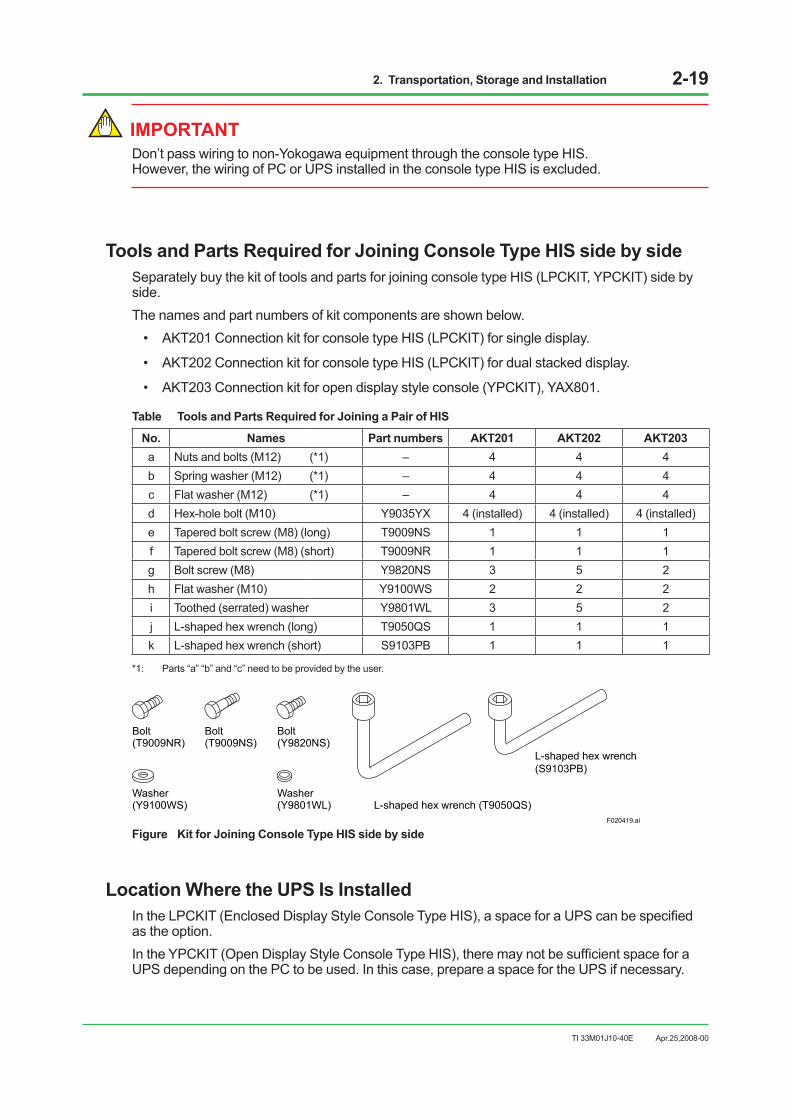
2. Transportation, Storage and Installation 2-19
TI 33M01J10-40E
IMPORTANT Don’t pass wiring to non-Yokogawa equipment through the console type HIS. However, the wiring of PC or UPS installed in the console type HIS is excluded.
Tools and Parts Required for Joining Console Type HIS side by sideSeparately buy the kit of tools and parts for joining console type HIS (LPCKIT, YPCKIT) side by side. The names and part numbers of kit components are shown below.
• AKT201 Connection kit for console type HIS (LPCKIT) for single display.
• AKT202 Connection kit for console type HIS (LPCKIT) for dual stacked display.
• AKT203 Connection kit for open display style console (YPCKIT), YAX801.
Table Tools and Parts Required for Joining a Pair of HIS
No. Names Part numbers AKT201 AKT202 AKT203 a Nuts and bolts (M12) (*1) – 4 4 4 b Spring washer (M12) (*1) – 4 4 4 c Flat washer (M12) (*1) – 4 4 4 d Hex-hole bolt (M10) Y9035YX 4 (installed) 4 (installed) 4 (installed) e Tapered bolt screw (M8) (long) T9009NS 1 1 1 f Tapered bolt screw (M8) (short) T9009NR 1 1 1 g Bolt screw (M8) Y9820NS 3 5 2 h Flat washer (M10) Y9100WS 2 2 2 i Toothed (serrated) washer Y9801WL 3 5 2 j L-shaped hex wrench (long) T9050QS 1 1 1 k L-shaped hex wrench (short) S9103PB 1 1 1
*1: Parts “a” “b” and “c” need to be provided by the user.
Bolt(T9009NR)
Washer(Y9100WS)
Washer(Y9801WL) L-shaped hex wrench (T9050QS)
L-shaped hex wrench (S9103PB)
F020419.ai
Bolt(T9009NS)
Bolt(Y9820NS)
Figure Kit for Joining Console Type HIS side by side
Location Where the UPS Is InstalledIn the LPCKIT (Enclosed Display Style Console Type HIS), a space for a UPS can be specified as the option.In the YPCKIT (Open Display Style Console Type HIS), there may not be sufficient space for a UPS depending on the PC to be used. In this case, prepare a space for the UPS if necessary.
Apr.25,2008-00
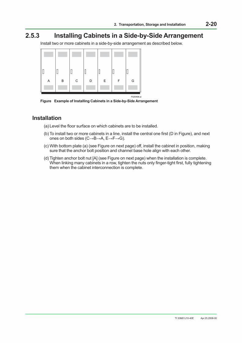
2. Transportation, Storage and Installation 2-20
TI 33M01J10-40E
2.5.3 Installing Cabinets in a Side-by-Side ArrangementInstall two or more cabinets in a side-by-side arrangement as described below.
C DBA GFE
F020408.ai
Figure Example of Installing Cabinets in a Side-by-Side Arrangement
Installation(a) Level the floor surface on which cabinets are to be installed.
(b) To install two or more cabinets in a line, install the central one first (D in Figure), and next ones on both sides (C→B→A, E→F→G).
(c) With bottom plate (a) (see Figure on next page) off, install the cabinet in position, making sure that the anchor bolt position and channel base hole align with each other.
(d) Tighten anchor bolt nut [A] (see Figure on next page) when the installation is complete. When linking many cabinets in a row, tighten the nuts only finger-tight first, fully tightening them when the cabinet interconnection is complete.
Apr.25,2008-00

2. Transportation, Storage and Installation 2-21
TI 33M01J10-40E
F020409.ai
Side plate
M4 screw
Side plate
Bottom plate (a)
[A]
[D]
[B][C]
[G]
[E]
[F]
[F]
Figure Installing Cabinets Side by Side
Interconnecting cabinets(a) Using a hexagon wrench, loosen hexagonal socket head bolts [D] (eight bolts) securing the
main body and the channel base to each other.
(b) With the front and rear doors open, clamp bolt screw [E], toothed washer [F] and nut [G] using a wrench (at eight positions on the front and rear in total).
(c) After verifying that the cabinet is level in all directions, clamp hexagonal socket head bolts [D] (eight bolts) securing the main body and the channel base to each other using a hexagonal wrench. If there is a gap between the main body and channel base when the hexagonal socket head bolts are clamped, insert liners into the gap for adjustment.
(d) Replace all bottom plates that have been removed in their original position.
SEE ALSO For details on the related tools and parts for joining cabinet’s side-by-side, refer to “Tools and Parts Required for
Joining Cabinets.”
Apr.25,2008-00

2. Transportation, Storage and Installation 2-22
TI 33M01J10-40E
Tools and Parts Required for Joining CabinetsConnecting kit to install cabinets side by side. Table lists those parts needed to connect two cabinets together.
- AKT211: Connection kit for Cabinet
Table Joining Parts and Tools (required per additional station)
No. Names Part numbers Quantity a Nut or bolt (M12) (*1) – 4 b Spring washer (M12) (*1) – 4 c Flat washer (M12) (*1) – 4 d Hex hole bolt (M10) – (Cabinet accessory) 8 e Bolt (M8) Y9820NS 8 f Toothed (serrated) washer (M8) Y9801WL 16 g Nut (M8) Y9801BS 8 h L-shaped hex wrench S9103PB 2
*1: Parts “a” “b” and “c” need to be provided by the user.
Bolt(Y9820NS)
Toothed washer(Y9801WL)
Nut(Y9801BS)
L-shaped hex wrench (S9103PB)
F020410.ai
Figure Cabinet Connecting Parts
Apr.25,2008-00

2. Transportation, Storage and Installation 2-23
TI 33M01J10-40E
2.5.4 19-inch Rack Mount DevicesRack-mount devices include AFS30S/AFS30D, AFG30S/AFG30D, AFS10S/AFS10D, AFG10S/AFG10D, AFF50S/AFF50D Field Control Unit, PFCS/PFCD Control Station, YNT511S/YNT511D, YNT522S/YNT522D Optical Bus Repeater, YNT512S/YNT512D Bus Repeater, ACG10S Communication Gateway Unit, ANS50/AND50 Node Interface Unit, ANB10S/ANB10D, ANR10S/ANR10D Node Unit for FIO and ABC11S/ABC11D Bus Converter.
CAUTION• Use 19-inch rack mount devices inside a keyed metallic cabinet, especially for Safety
standard and CE Mark.
• Do not install them next to each other. When installing an 19-inch rack mount devices on the same rack, use 3-unit spacing (*1) (1 unit: 44.45 mm) between devices.
*1: Space between devices can be smaller than 3U to the extent it does not interfere device mounting and maintenance, only if thermal design for the cabinet interior is done and ambient temperature is within the product specifications.
Notes on Installation
IMPORTANT For installation, secure ample working space and work in a team for safety.
Be sure to observe the following when installing in the rack or on an instrumentation panel:
Attaching BracketsThere are the 19-inch rack mountable devices that the positions of their brackets can be changed according to the front and rear space of the rack. Before attaching the devices to the instrumentation panel or rack, change bracket positions as shown below, if necessary: For example, the optical bus repeaters (YNT511S/YNT511D, YNT522S/YNT522D) and bus repeater (YNT512S/YNT512D) can be mounted in one of three positions located depth-wise.The mounting bracket positions of the optical bus repeater are shown below.
Apr.25,2008-00
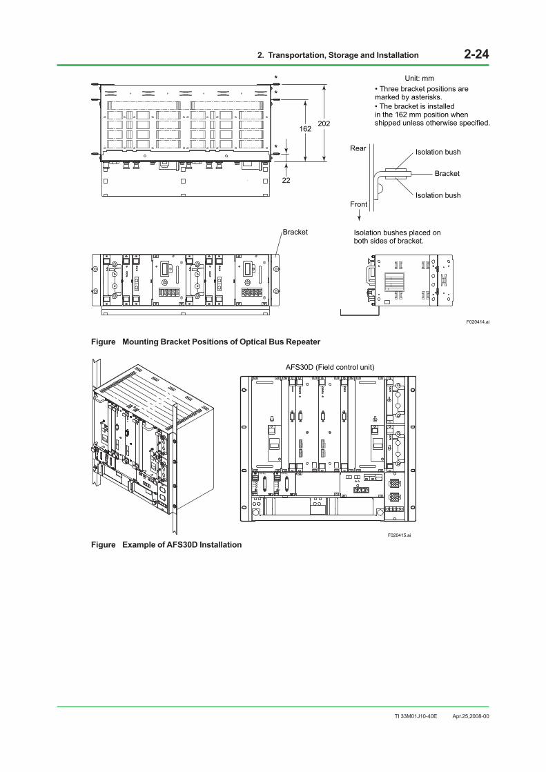
2. Transportation, Storage and Installation 2-24
TI 33M01J10-40E
202162
22
F020414.ai
*
• Three bracket positions aremarked by asterisks.
**
Bracket
Unit: mm
Rear
Front
Isolation bush
Isolation bush
Bracket
Isolation bushes placed on both sides of bracket.
• The bracket is installedin the 162 mm position when shipped unless otherwise specified.
Figure Mounting Bracket Positions of Optical Bus Repeater
F020415.ai
AFS30D (Field control unit)
REVISIONU H1 H2
MODELAIP532
STYLE1 SIYOKOGAWA
ESB BusCN1
RCV
SND-L
SND-R
REVISIONU H1 H2
MODELAIP532
STYLE1 SIYOKOGAWA
ESB BusCN1
RCV
SND-L
SND-R
REVISIONUH1 H2
MODELAIP532STYLE1 SI
YOKOGAWA
ESB BusCN1
RCVSND-LSND-R
REVISIONUH1 H2
MODELAIP532STYLE1 SI
YOKOGAWA
ESB BusCN1
RCVSND-LSND-R
Figure Example of AFS30D Installation
Apr.25,2008-00

2. Transportation, Storage and Installation 2-25
TI 33M01J10-40E
F020411.ai
Figure Example of PFCD Mounting
F020516.ai
Figure Example of ANR10D Mounting
Apr.25,2008-00

2. Transportation, Storage and Installation 2-26
TI 33M01J10-40E
Isolation from RackIsolate the rack mountable devices from the rack by attaching isolation bushings. Fasten a pair of isolation bushings together to each of the screw holes on the plate or the bracket on the devices to prevent the devices from touching the rack. And then screw the devices to the rack. After screwing the devices to the rack, confirm that the devices is electrically isolated. Isolation bushings are supplied with the rack mountable devices.
CAUTIONWhen you install the ‘devices with isolation bushings attached’ on a rack or an instrument panel, do not keep the devices hung on loose screws in an unstable status. Too much force may apply to the isolation bushings and cause damaged or broken isolation bushings.
Installation Procedure 1. Fasten a pair of isolation bushings together to each of the screw holes on the plate or the
bracket on the device. The tapering end of the isolation bushings must come to the front side where a screw enters.
2. Using eight M5 screws to fix the device onto the rack or the panel.
F020413.ai
Input/output module slots
Power supply module
Processor module
Cable tray
Using grounding terminal to connect the base unit to earth (less than 100 ohm). Make the grounding cable to pass throughthe tray and pull it down along the right side of the racks.
M5 screws (8 pieces)
M5 screws
Attach isolation to both sides of the plate.
How to install isolation bushings
Rack
Rack
Isolation bushing(with a tapering)
Isolation bushing
Plate(front)
Isolation bushings (8 pieces)
Plate
Base unit
Figure Example of Mounting FFCS on a Rack
Apr.25,2008-00
2. Transportation, Storage and Installation 2-27
TI 33M01J10-40E
Isolation BushIn the front of the I/O expansion cabinet (ACB21, ACB41): for cabinet installation type node and the rear: for 19-inch rack mount type (ACB1-S20), the cabinet installation type node is installed in the front. For this node, the independent grounding plays an important role in the circuit systems. Therefore, in order that the rear 19-inch rack mount devices do not pass the grounding current which is important to the node, it and devices manufactured by other companies, must be insulated with an insulation brush. As devices manufactured by Yokogawa (Models ACG10S, ABC11S/ABC11D, etc.) also do not have the guarantee that it will share a common power supply or grounding with the Model ACB21 or ACB41 itself, make sure to insulate with an isolation bush.In the front and rear of the I/O expansion cabinet: (ACB1-S30) installing 19-inch rack mount devices, the installed devices cannot restrict, similar in panels. Therefore, to ensure that problems will not occur whatever is connected to the grounding, insulate Yokogawa devices (Models ACG10S, ABC11S/ABC11D, etc.) with the isolation bush.
TIPThe isolation bush of Yokogawa devices can be eliminated if both I/O expansion cabinet types are installing Yokogawa devices (Models ACG10S, ABC11S/ABC11D, etc.) and shares a common power supply and grounding with Model ACB21, ACB41, and only when other company devices are insulated with an isolation bush.
Installation DirectionPlease install the device in the rack with the screws in the vertically correct direction.Please check the installation direction by referring to SD (External Dimensions).
TIPWhen the device is supplied with power even if it is temporary, the device must be installed on the rack. Placing the device on a desk etc. and laying it on its side should be avoided. The device may become malfunction if the heat radiated from the device cannot be cooled smoothly.
Providing Space for Heat RadiationLeave space at the top and bottom of rack-mount equipment to permit heat radiation.
• Separate the top of the instrumentation board at least 100 mm away from the ceiling, and cut a ventilation hole of 200 cm2 or larger in the ceiling or install a ventilation fan.
• Keep at least 50 mm between the back of the equipment and the instrumentation panel or wall.
• When installing an 19-inch rack mount devices on the same rack, use 3-unit spacing (1 unit: 44.45 mm) between devices. Do not use any space between equipments for cable wiring or anything.
• Do not block ventilation openings in top and bottom face of equipment.
Apr.25,2008-00

2. Transportation, Storage and Installation 2-28
TI 33M01J10-40E
Providing Area for ServicingLeave about at least 1000 mm of space at the front of the equipment for:
• Cabling to 19-inch rack mount devices, or I/O modules.
• Indicator lamp confirmation, making card settings, inspection, card mounting/dismounting, and maintenance.
F020412.ai
CeilingVentilation fan
Front
Servicing area
3 units or more
50 mm or more
100 mm or more
1000 mm or more
Figure Space Required for Rack-mount Equipment
Apr.25,2008-00

2. Transportation, Storage and Installation 2-29
TI 33M01J10-40E
2.5.5 Desktop EquipmentThere are general-purpose PCs, printers, etc. as the devices used on the desks.
When installing any devices on the desks, take care the followings:• It should provide a level horizontal surface for the PC or the printer.
• A work space should be preserved to connect the cables.
• Support rising cables to prevent their weight from being applied to connectors directly. Keep a space of 100 mm radius or more around the connectors.
• Do not place the desk such as to expose the PC to direct sunlight or high humidity.
Apr.25,2008-00
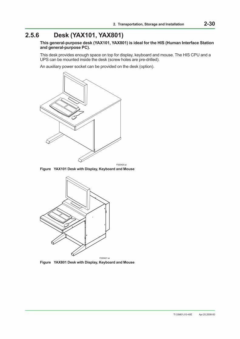
2. Transportation, Storage and Installation 2-30
TI 33M01J10-40E
2.5.6 Desk (YAX101, YAX801)This general-purpose desk (YAX101, YAX801) is ideal for the HIS (Human Interface Station and general-purpose PC).
This desk provides enough space on top for display, keyboard and mouse. The HIS CPU and a UPS can be mounted inside the desk (screw holes are pre-drilled).An auxiliary power socket can be provided on the desk (option).
F020420.ai
Figure YAX101 Desk with Display, Keyboard and Mouse
F020421.ai
Figure YAX801 Desk with Display, Keyboard and Mouse
Apr.25,2008-00

2. Transportation, Storage and Installation 2-31
TI 33M01J10-40E
2.5.7 Installing Control Bus Interface CardThis section describes how to install VF701 Control Bus interface card. The card is installed in the expansion PCI slot of a PC/AT compatible general-purpose PC to connect it to the Control Bus. The card permits you to use CENTUM VP system operation and monitoring functions on the PC when used with the dedicated software.
SEE ALSO • The steps described below are based on a common PC/AT compatible machine. Refer to the manual of the
PC to be used for precise instructions.
• For station address setting, refer to “Peripherals Manual (A4. Control Bus Interface Card)” (IM 33M50C10-40E).
Card Installation Procedure1. Set a station address for the Control Bus interface card.2. Turn off the computer and unplug the power cord to ensure safety.3. Remove the screws from the computer cover and remove the cover.4. Remove the screws from the expansion card slot cover and remove the cover.5. Insert the Control Bus interface card in the PCI expansion slot. Make certain that the card is
properly set in the slot.6. Clamp the Control Bus interface card using the screws removed in Step 4.7. Attach the computer cover.8. Write the station address on a seal (sticker) and attach it to the front of the PC or a similar
highly-visible place.
SEE ALSO For electrostatic protection, refer to Item 1.5.2, “Countermeasures against Static Electricity.”
Apr.25,2008-00
3. Cabling 3-1
TI 33M01J10-40E
3. CablingThis section describes how to cable the installed system equipment.
Connecting terminals for power, grounding, and signal cables are shown in figures.
The figures also show how to connect the HIS-connected Control Bus interface card to Field Control Units, and an optical fiber cable to the optical bus repeater.
Apr.25,2008-00

3. Cabling 3-2
TI 33M01J10-40E
3.1 Cables and TerminalsIt is recommended that you use flexible, thin, easy-to-bend, twisted-pair cables to connect the terminals of the system equipment. Use solderless (crimp-on) terminals with insulating cover, which have low contact resistance little aging.
Rigid cables make cabling work difficult and exert unnecessary force on the terminals, which may result in system failures.
Signal Cables• Nominal conductor cross-sectional area: 0.75 to 2.00 mm2
Example of Suitable Cables: 600 V vinyl isolated cable (IV); JIS C 3307 Vinyl isolated wire (KIV); JIS C 3316 600 V vinyl isolated cable type 2 (HIV); JIS C 3317 Heat-proof vinyl isolated wire (UL1015/UL1007) Vinyl isolated sheath cable for control loop (CVV); JIS C 3401
• Solderless (crimp-on) terminal: Circular solderless terminal (for use with M4 screws)
Alarm and Control Circuit Cables• Nominal conductor cross-sectional area: 0.5 to 1.25 mm2
Example of Suitable Cables: 600 V vinyl isolated cable (IV); JIS C 3307 Vinyl isolated wire (KIV); JIS C 3316 Heat-proof vinyl-insulated wire (UL1007)
• Solderless (crimp-on) terminal: Circular solderless terminal (for use with M4 screws)
Power Cables• Nominal conductor cross-sectional area
For rack-mounted AC 100-120/220-240 V-driven equipment: 1.25 to 2.0 mm2 For rack-mounted DC 24 V-driven equipment: Minimum 2.0 mm2 For cabinets and console HISs: Minimum 8.0 mm2 Example of suitable cables: 600 V vinyl isolated cable (IV); JIS C 3307 Vinyl isolated wire (KIV); JIS C 3316
• Solderless (crimp-on) terminal lugs: Circular solderless terminal lugs for M4 or M6 screw terminal
Note: Use cables capable of supplying current required by respective pieces of equipment with low voltage drop.
Apr.25,2008-00

3. Cabling 3-3
TI 33M01J10-40E
Grounding Cables
SEE ALSO See Section 1.4, “Grounding,” for wiring of grounding cables connecting grounding bars of different cabinets
and/or panels to each other.
• Nominal conductor cross-sectional area For rack-mounted equipment: Minimum 2.0 mm2 Grounding cables connecting cabinets and console HISs to grounding bus: Minimum 5.5 mm2 Grounding buses connected to cabinets and console HISs: Minimum 22.0 mm2 Example of suitable cables: 600 V vinyl isolated cable (IV); JIS C 3307 Vinyl insulated wire (KIV); JIS C 3316
• Solderless (crimp-on) terminal lugs For rack mounted equipment: Circular solderless terminal lugs for M4 screw terminal For cabinets and console HISs: Circular solderless terminal lugs for M5 or M8 hexagonal bolt
Cable TerminalsUse the specified solderless terminals and sleeves for pressure clamp terminal on the end of terminal-connected cables, providing low contact resistance, high durability, and low aging.
Solderless Lug
IMPORTANT • Be sure to use solderless terminals with insulating sheath.
• Use solderless terminals and crimp tools from the same maker.
• Use different crimp tools according to cable size.
F030101.ai
Figure Solderless Terminal with Insulating Sheath
Apr.25,2008-00
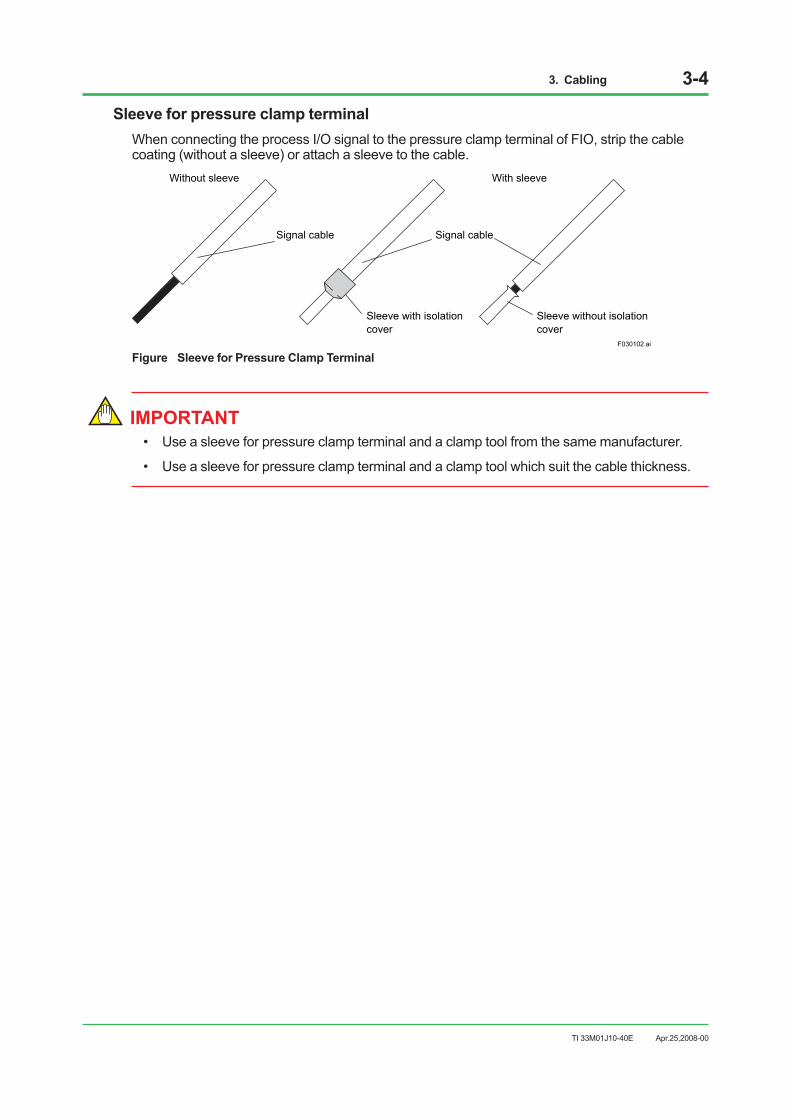
3. Cabling 3-4
TI 33M01J10-40E
Sleeve for pressure clamp terminalWhen connecting the process I/O signal to the pressure clamp terminal of FIO, strip the cable coating (without a sleeve) or attach a sleeve to the cable.
Signal cable Signal cable
Without sleeve With sleeve
Sleeve with isolation cover
Sleeve without isolation cover
F030102.ai
Figure Sleeve for Pressure Clamp Terminal
IMPORTANT • Use a sleeve for pressure clamp terminal and a clamp tool from the same manufacturer.
• Use a sleeve for pressure clamp terminal and a clamp tool which suit the cable thickness.
Apr.25,2008-00
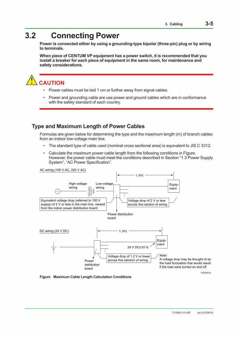
3. Cabling 3-5
TI 33M01J10-40E
3.2 Connecting PowerPower is connected either by using a grounding-type bipolar (three-pin) plug or by wiring to terminals.
When piece of CENTUM VP equipment has a power switch, it is recommended that you install a breaker for each piece of equipment in the same room, for maintenance and safety considerations.
CAUTION• Power cables must be laid 1 cm or further away from signal cables.
• Power and grounding cable are use power and ground cables which are in conformance with the safety standard of each country.
Type and Maximum Length of Power CablesFormulas are given below for determining the type and the maximum length (m) of branch cables from an indoor low-voltage main line.
• The standard type of cable used (nominal cross sectional area) is equivalent to JIS C 3312.
• Calculate the maximum power cable length from the following conditions in Figure. However, the power cable must meet the conditions described in Section “1.3 Power Supply System”, “AC Power Specification”.
Low-voltagewiring
Power dstribution board
Power distribution board
Equivalent voltage drop (referred to 100 V supply) of 2 V or less in the main line, viewed from the indoor power distribution board
Voltage drop of 2 V or lessacross this section of wiring
Equip-ment
L (m)AC wiring (100 V AC, 220 V AC)
High-voltagewiring
Voltage drop of 1.2 V or loweracross this setction of wiring
L (m)
24 V DC±10 %
DC wiring (24 V DC)
Note:A voltage drop may be thought of as the load fluctuation that would resultif the load were turned on and off.
F030205.ai
Equip-ment
Figure Maximum Cable Length Calculation Conditions
Apr.25,2008-00

3. Cabling 3-6
TI 33M01J10-40E
[Maximum power cable length calculation conditions]Use the following formula to calculate the maximum power cable length:(a) 100 V AC and 220 V AC supply voltages
F030206.ai
L (m)=Voltage drop across wiring
Conductor resistance (ohm/km)×(Number of cores)×Equipment current consumption× 1000
(b) 24 V DC supply voltage
F030207.ai
L (m)=Voltage drop across wiring
Conductor resistance (ohm/km)×(Number of cores)×Equipment current consumption× 1000
Note: In the formulas above, the voltage drop across wiring is assumed to be 2 V for AC power supplies and 1.2 V for DC power supplies; the number of cores is two; and the conductor resistance is as specified in the table below.
Table Wire Nominal Cross Sectional Areas and Resistances
Wire nominal cross sectional area 5.5 mm2 8 mm2 14 mm2 22 mm2 Wire conductor resistance 3.37 ohm/km 2.39 ohm/km 1.36 ohm/km 0.82 ohm/km
Apr.25,2008-00
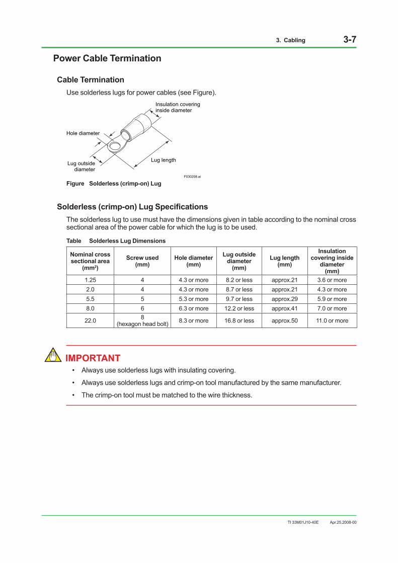
3. Cabling 3-7
TI 33M01J10-40E
Power Cable Termination
Cable TerminationUse solderless lugs for power cables (see Figure).
F030208.ai
Insulation covering inside diameter
Hole diameter
Lug outsidediameter
Lug length
Figure Solderless (crimp-on) Lug
Solderless (crimp-on) Lug SpecificationsThe solderless lug to use must have the dimensions given in table according to the nominal cross sectional area of the power cable for which the lug is to be used.
Table Solderless Lug Dimensions
Nominal cross sectional area
(mm2) Screw used
(mm) Hole diameter
(mm) Lug outside
diameter (mm)
Lug length (mm)
Insulation covering inside
diameter (mm)
1.25 4 4.3 or more 8.2 or less approx.21 3.6 or more 2.0 4 4.3 or more 8.7 or less approx.21 4.3 or more 5.5 5 5.3 or more 9.7 or less approx.29 5.9 or more 8.0 6 6.3 or more 12.2 or less approx.41 7.0 or more
22.0 8 (hexagon head bolt) 8.3 or more 16.8 or less approx.50 11.0 or more
IMPORTANT • Always use solderless lugs with insulating covering.
• Always use solderless lugs and crimp-on tool manufactured by the same manufacturer.
• The crimp-on tool must be matched to the wire thickness.
Apr.25,2008-00

3. Cabling 3-8
TI 33M01J10-40E
Power Distribution BoardsPower distribution boards are normally provided by the customer. Figures show examples of AC and DC power distribution boards.
AC Power Distribution BoardThe power cables is branched to each unit by way of a circuit breaker.Each power system uses three terminals (AC and ground: ISO M4 to M6 screws).
Unit
Unit
Unit
Power distribution board
100-120 V AC or220-240 V AC
F030209.ai
Figure AC Power Distribution Board
24 V DC Power Distribution Board
Unit
Unit
Unit
Power distribution board
24 V DC
F030210.ai
Figure 24 V DC Power Distribution Board
Apr.25,2008-00
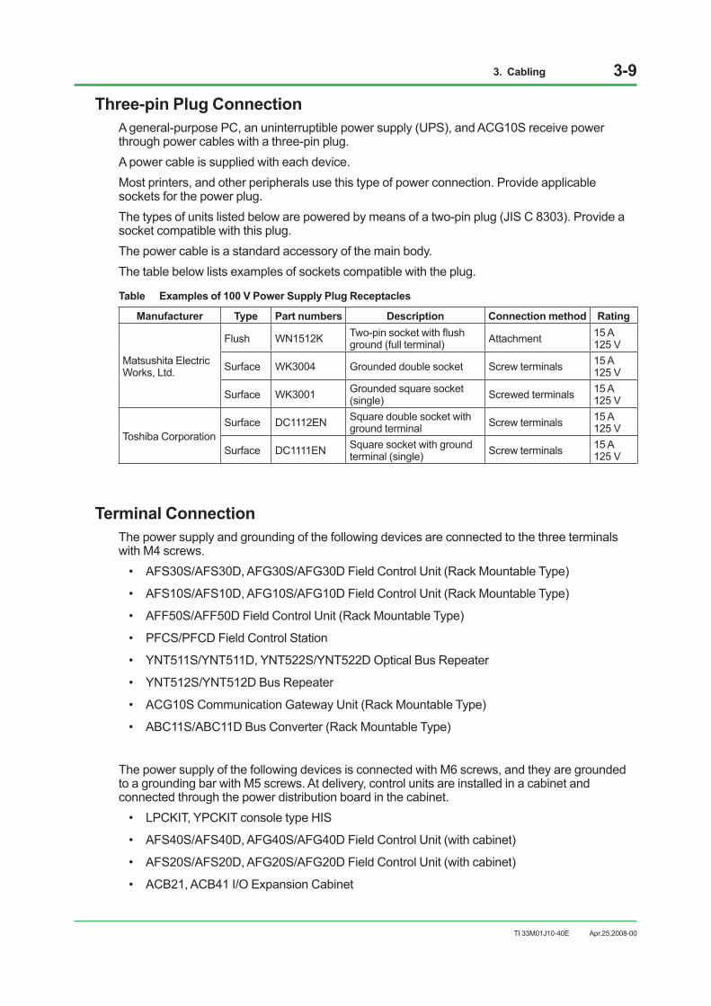
3. Cabling 3-9
TI 33M01J10-40E
Three-pin Plug ConnectionA general-purpose PC, an uninterruptible power supply (UPS), and ACG10S receive power through power cables with a three-pin plug.A power cable is supplied with each device.Most printers, and other peripherals use this type of power connection. Provide applicable sockets for the power plug.The types of units listed below are powered by means of a two-pin plug (JIS C 8303). Provide a socket compatible with this plug.The power cable is a standard accessory of the main body.The table below lists examples of sockets compatible with the plug.
Table Examples of 100 V Power Supply Plug Receptacles
Manufacturer Type Part numbers Description Connection method Rating
Matsushita Electric Works, Ltd.
Flush WN1512K Two-pin socket with flush ground (full terminal) Attachment 15 A
125 V
Surface WK3004 Grounded double socket Screw terminals 15 A 125 V
Surface WK3001 Grounded square socket (single) Screwed terminals 15 A
125 V
Toshiba Corporation Surface DC1112EN Square double socket with
ground terminal Screw terminals 15 A 125 V
Surface DC1111EN Square socket with ground terminal (single) Screw terminals 15 A
125 V
Terminal ConnectionThe power supply and grounding of the following devices are connected to the three terminals with M4 screws.
• AFS30S/AFS30D, AFG30S/AFG30D Field Control Unit (Rack Mountable Type)
• AFS10S/AFS10D, AFG10S/AFG10D Field Control Unit (Rack Mountable Type)
• AFF50S/AFF50D Field Control Unit (Rack Mountable Type)
• PFCS/PFCD Field Control Station
• YNT511S/YNT511D, YNT522S/YNT522D Optical Bus Repeater
• YNT512S/YNT512D Bus Repeater
• ACG10S Communication Gateway Unit (Rack Mountable Type)
• ABC11S/ABC11D Bus Converter (Rack Mountable Type)
The power supply of the following devices is connected with M6 screws, and they are grounded to a grounding bar with M5 screws. At delivery, control units are installed in a cabinet and connected through the power distribution board in the cabinet.
• LPCKIT, YPCKIT console type HIS
• AFS40S/AFS40D, AFG40S/AFG40D Field Control Unit (with cabinet)
• AFS20S/AFS20D, AFG20S/AFG20D Field Control Unit (with cabinet)
• ACB21, ACB41 I/O Expansion Cabinet
Apr.25,2008-00

3. Cabling 3-10
TI 33M01J10-40E
Conduit Power-cablingConduit cabling using cable glands is recommended to lay a power cable for the cabinet and instrumentation boards. It prevents the power cable from contacting metallic plates and putting its weight on power connection terminal.The console type HIS, or cabinet, has a conduit hole in the bottom plate directly below the terminal box, and the hole can be exposed by removing the blank plate screwed to the bottom. See figures below for conduit cabling:
F030203.ai
Blank plate (not needed after cabling)
Bottom plate
Conduit hole
Cable gland (clamps cable to tighten it)
Power cable
Figure Conduit Hole & Cable Gland
F030204.ai
Power input terminal box
Cable gland
Bottom plate
Bottom plate Ground bar
Channel base
Figure Conduit Cabling
Conduit cabling is also recommended for the 19-inch rack-mount equipment, laying a power cable through a conduit hole where the cable enters the metallic cabinet.
Apr.25,2008-00

3. Cabling 3-11
TI 33M01J10-40E
3.3 Connecting Ground CableConnect ground cables as follows:
CAUTION• Connect the terminal connection type device to the ground terminal.
• Connect LPCKIT, YPCKIT, AFS40S/AFS40D, AFG40S/AFG40D, AFS20S/AFS20D, AFG20S/AFG20D, ACB41, and ACB21 to the relay terminal of the ground bar for connecting a ground cable with M5 screws.
• Connect a power cable of the plug-in device to a grounded socket. The cabinet is grounded when the power cable is plugged in.
Apr.25,2008-00
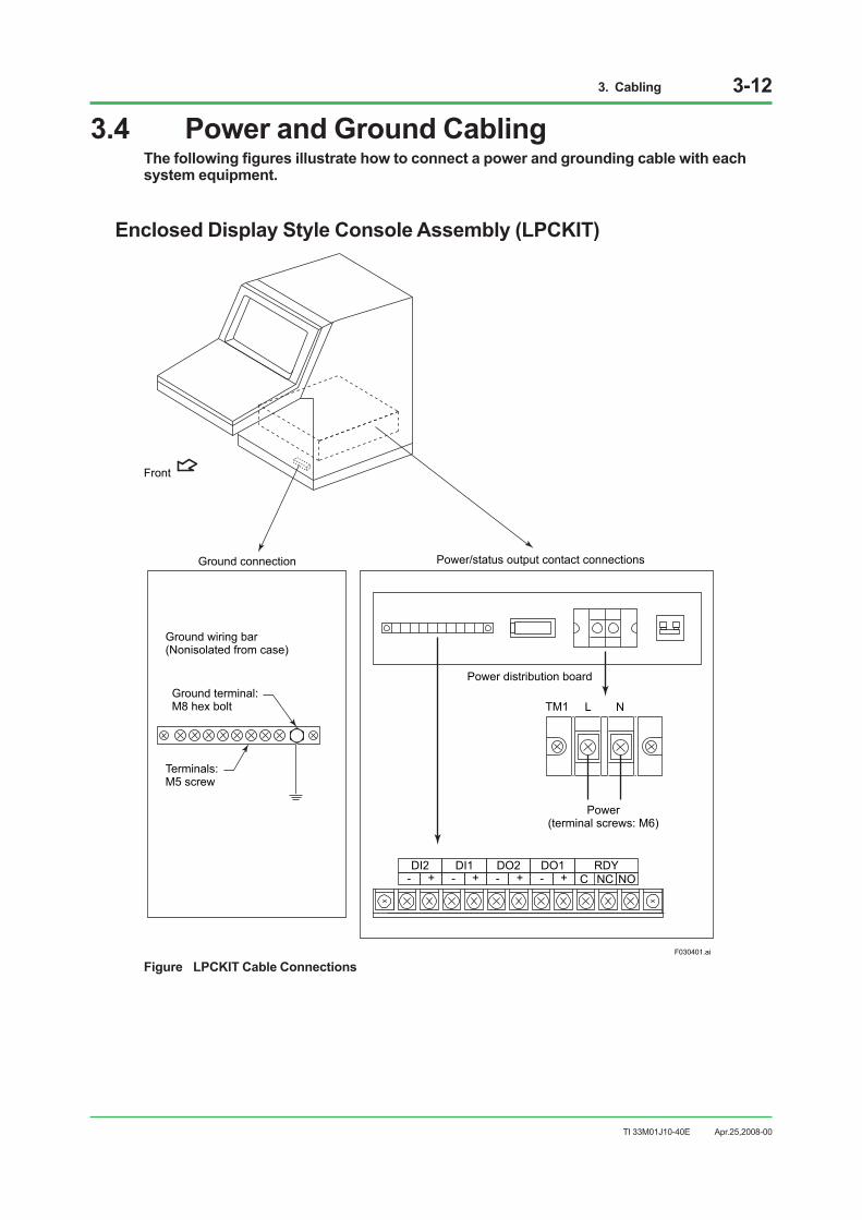
3. Cabling 3-12
TI 33M01J10-40E
3.4 Power and Ground CablingThe following figures illustrate how to connect a power and grounding cable with each system equipment.
Enclosed Display Style Console Assembly (LPCKIT)
Ground wiring bar(Nonisolated from case)
Power distribution board
Power(terminal screws: M6)
NTM1 L
F030401.ai
Front
Ground connection Power/status output contact connections
Ground terminal:M8 hex bolt
Terminals:M5 screw
DI2+- - - -+ + + C NC NO
DI1 DO2 DO1 RDY
Figure LPCKIT Cable Connections
Apr.25,2008-00

3. Cabling 3-13
TI 33M01J10-40E
Open Display Style Console Assembly (YPCKIT)
Ground wiring bar(Nonisolated from case)
Power distribution board
Power(Terminal screw: M6)
NTM1 L
F030402.ai
Front
Ground connection Power/status output contact connections
Example dual stacked LCD
DI2+- - - -+ + + C NC NO
DI1 DO2 DO1 RDY
Ground terminal:M8 hex bolt
Terminals:M5 screw
Figure YPCKIT Cable Connection
Apr.25,2008-00

3. Cabling 3-14
TI 33M01J10-40E
AFS10S/AFS10D, AFG10S/AFG10D Field Control Unit (19-inch Rack Mountable Type)
1 2 3
4 5 6
F030409.ai
L NREADY
TM1
TM1
Power supply(Terminal screw: M4)
READY contacts(Terminal screw: M4)
RIO bus coupler(Refer to “Section 3.8 RIO Bus”)
Figure AFS10S/AFS10D, AFG10S/AFG10D Cable Connections
IMPORTANT If wiring the contact output cable to the READY contact output terminals, attach a clamp filter (part No. A1193MN with cable fastener) supplied with AFS10S/AFS10D and AFG10S/AFG10D, near the terminals. This inside diameter of the core is 9±1 mm.
F030410.ai
READY
TM1
FUSE
RL1 RL2FAN ALARM
N1 N2
Clamp Filter
Contact OutputTerminals
Contact Output Terminals (external interface unit)
Figure Clamp Filter
Apr.25,2008-00
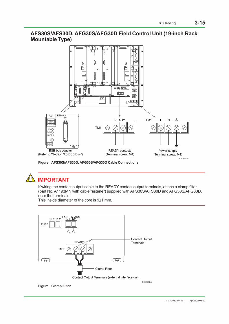
3. Cabling 3-15
TI 33M01J10-40E
AFS30S/AFS30D, AFG30S/AFG30D Field Control Unit (19-inch Rack Mountable Type)
F030405.ai
L NREADY
TM1
TM1
Power supply(Terminal screw: M4)
READY contacts(Terminal screw: M4)
ESB bus coupler(Refer to “Section 3.8 ESB Bus”)
REVISIONU H1 H2
MODELAIP532
STYLE1 SIYOKOGAWA
ESB BusCN1
RCV
SND-L
SND-R
REVISIONU H1 H2
MODELAIP532
STYLE1 SIYOKOGAWA
ESB BusCN1
RCV
SND-L
SND-R
REVISIONU H1 H2
MODELAIP532
STYLE1 SIYOKOGAWA
ESB BusCN1
RCV
SND-L
SND-R
Figure AFS30S/AFS30D, AFG30S/AFG30D Cable Connections
IMPORTANT If wiring the contact output cable to the READY contact output terminals, attach a clamp filter (part No. A1193MN with cable fastener) supplied with AFS30S/AFS30D and AFG30S/AFG30D, near the terminals. This inside diameter of the core is 9±1 mm.
F030410.ai
READY
TM1
FUSE
RL1 RL2FAN ALARM
N1 N2
Clamp Filter
Contact OutputTerminals
Contact Output Terminals (external interface unit)
Figure Clamp Filter
Apr.25,2008-00

3. Cabling 3-16
TI 33M01J10-40E
AFS20S/AFS20D, AFG20S/AFG20D Field Control Unit (with Cabinet), AFS40S/AFS40D, AFG40S/AFG40D Field Control Unit (with Cabinet) ACB21 I/O Expansion Cabinet, ACB41 I/O Expansion Cabinet
Grounding bar for function grounding(isolated from frame)By removing the cablebetween grounding barof the groundingconductor connection,it can be used isolatedfrom the frame
Grounding conductor connection
Wire from the wiring holes rightunderneath the power supply or contactconnection terminals(remove the square plates for conduitholes)
Power cable connection/status contact output connection
Grounding conductorterminal: M8hexagon head bolt
Terminals:M5 screw
Front
Front
Grounding conductorconnection grounding bar(not isolated from frame)
Powerdistributionboard
Dual power connection
Power supply(Terminal screw: M6)
Power supply(Terminal screw: M6)
READY output contact terminals
(Terminal screw: M4)
Dual power connection is available only forduplexed FCSs (with cabinet) or ACB.
TM1 L N NTM1 LREADY
F030411.ai
Figure Cabinet Cable Connections
Apr.25,2008-00
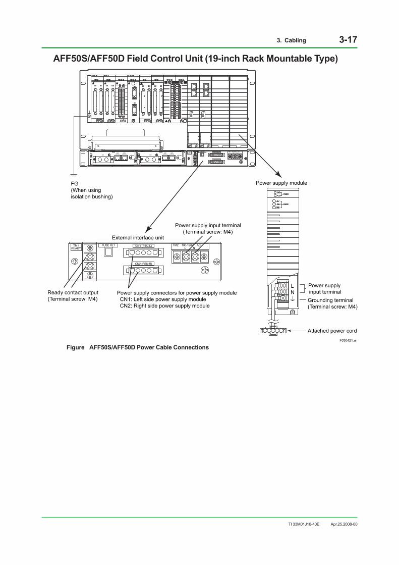
3. Cabling 3-17
TI 33M01J10-40E
AFF50S/AFF50D Field Control Unit (19-inch Rack Mountable Type)
CN2(CPU-L)
CN3(CPU-R)
CN1 ENBL
DSBL
CN2(CPU-L)
CN3(CPU-R)
TM1READY
FUSE RL1
CN1 ENBL
DSBL
CN1 (PSU-L) TM2 100-120V AC , L N
CN2 (PSU-R)
TM1READY
FUSE RL1 CN1 (PSU-L) TM2 100-120V AC , L N
CN2 (PSU-R)
F030421.ai
Power supply module
External interface unit
Power supply input terminal(Terminal screw: M4)
Grounding terminal(Terminal screw: M4)
Attached power cord
Power supply input terminalReady contact output
(Terminal screw: M4)
LN
FG(When usingisolation bushing)
Power supply connectors for power supply module CN1: Left side power supply module CN2: Right side power supply module
Figure AFF50S/AFF50D Power Cable Connections
Apr.25,2008-00

3. Cabling 3-18
TI 33M01J10-40E
PFCS/PFCD Field Control Station
CN1(PSU-L) CN2(PSU-R)TM1
L
N
100-120
TM1
L
N
VAC
220-240
TM1
+
-
DC24V
VAC
F030404.ai
Power input terminals
For 220-240V AC
For 24V DC
Grounding terminal
Figure PFCS/PFCD Power Cable Connections
Apr.25,2008-00
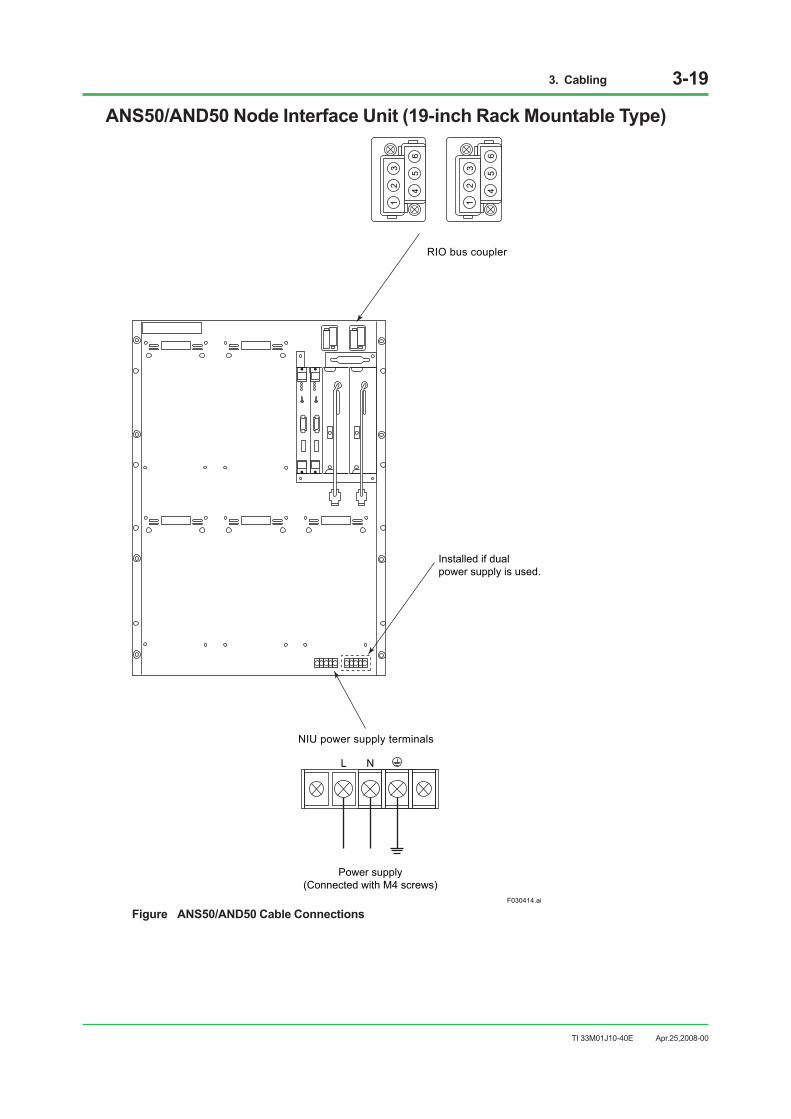
3. Cabling 3-19
TI 33M01J10-40E
ANS50/AND50 Node Interface Unit (19-inch Rack Mountable Type)
F030414.ai
12
3
45
6
12
3
45
6
RIO bus coupler
NIU power supply terminals
L N
Power supply(Connected with M4 screws)
Installed if dualpower supply is used.
Figure ANS50/AND50 Cable Connections
Apr.25,2008-00

3. Cabling 3-20
TI 33M01J10-40E
Power Wiring When Connecting Dual Power Supply LinesWhen installing an AND50 to an ACB21 I/O expansion cabinet, abide by the following: 1. Do not connect the shield wire of either power supply cable to the power distribution board
in the ACB21. Cut off the shields at the ends of the insulation for both cables. 2. Connect the conductors of each power supply cable to the L and N terminals on the power
distribution board in the ACB21. 3. For power wiring to the AND50 (dual power connection model), connect the L and N
terminals on power distribution board to the L and N terminals of the AND50, respectively, as shown in the figure below. Connect the G terminals of the AND50 to the grounding bar of the cabinet.
4. For the grounding of an entire cabinet, connect the grounding bar of the cabinet to the dedicated grounding bus or pole at a grounding resistance of 100 ohms or less.
AND50
100 ohms or less
Grounding bar
Power cables
ACB21
L N L N
L GN L GN
F030419.ai
Figure Power Wiring When Connecting Dual Power Supply Lines
Apr.25,2008-00

3. Cabling 3-21
TI 33M01J10-40E
ANB10S/ANB10D ESB Bus Node Unit (19-inch Rack Mountable Type)
F030420.ai
When not using the attached power cord,uncover and remove its cord, then connecta power cable and a grounding cable.
Power supply module
Power supply(Connected with M4 screws)
LN Power input terminals
Attached Power Cord
Grounding terminal
Cover
ESB bus connectionFG(When usingisolation bushing)
Figure ANB10S/ANB10D Power Cable Connection
Apr.25,2008-00

3. Cabling 3-22
TI 33M01J10-40E
ANR10S/ANR10D ER Bus Node Unit (19-inch Rack Mountable Type)
F030412.ai
ER bus connection
When not using the attached power cord,uncover and remove its cord, then connecta power cable and a grounding cable.
Power supply module
Supply power(Connected with M4 screws)
LN Power input terminals
Attached Power Cord
Grounding terminals
Cover
FG(When usingisolation bushing)
Figure ANR10S/ANR10D Power Cable Connection
Apr.25,2008-00

3. Cabling 3-23
TI 33M01J10-40E
An example of installing an ER Bus Node Unit in a general-purpose cabinet along with an AEP7D Primary Power Supply Bus Unit is shown.
L N
L N
TM2
100-12
0V AC
,
TM1
100-12
0V AC
,
ANR10S/ANR10D
F030422.ai
AEP7D
ANR10S/ANR10D
General-purposeCabinet
Figure Example of Installing ANR10S/ANR10D in a General-purpose Cabinet (Dual AC Power Supply Line)
Apr.25,2008-00

3. Cabling 3-24
TI 33M01J10-40E
19-inch Rack-mount Devices and WiringAn example of wiring when AFF50 or ANB10 is mounted to a general-purpose cabinet in the following:
F030423.ai
General-purpose Cabinet
3 units spacingbetween devices (*1)
AFF50
Node Unit
Node Unit
Node Unit
AEP7D
Ground terminal
Grounding bar
Cabinet ground
FG
Ground bus inlet
100 ohrmsor less
Insulating plate
Power
Isolated
Isolation bush
*1: Keep a space of 3U or more for heat radiation.
Figure 19-inch Rack-mount Devices and Wiring
Apr.25,2008-00

3. Cabling 3-25
TI 33M01J10-40E
YNT511S/YNT511D, YNT522S/YNT522D Optical Bus Repeater
RDYRCVSND
OUT
IN
OPTICALLINK
210
ERR
RDYRCVSND
CN1
CN2
RDYRCVSND
OUT
IN
OPTICALLINK
210
ERR
RDYRCVSND
CN1
CN2100-120VAC
FUSE
POWER
250V 1A
L N 100-120VAC
FUSE
POWER
250V 1A
L N
F030406.ai
L N
Power input terminals Grounding
terminal(Connected with M4 screws)
Figure Optical Bus Repeater Power Cable Connection
YNT512S/YNT512D Bus Repeater
F030407.ai
L N
Power input terminals Grounding
terminal(Connected with M4 screws)
Figure Bus Repeater Power Cable Connection
Apr.25,2008-00

3. Cabling 3-26
TI 33M01J10-40E
ACG10S Communication Gateway Unit
F030415.ai
LTM1 N
Desktop Type
19-inch Rack Mountable Type
Socket
Power input terminals Grounding
terminal(Connected with M4 screws)
Figure ACG10S Power Cable Connection
Apr.25,2008-00
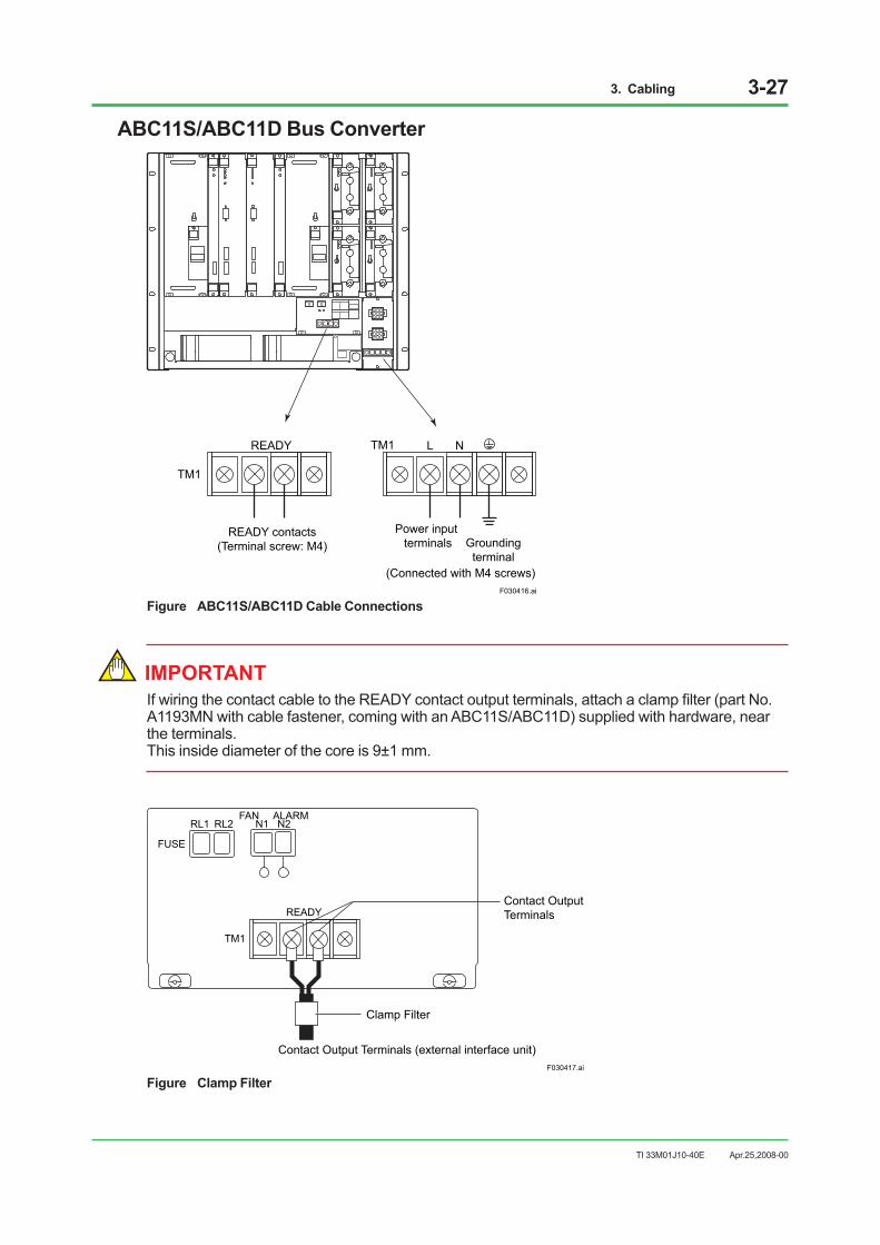
3. Cabling 3-27
TI 33M01J10-40E
ABC11S/ABC11D Bus Converter
F030416.ai
L NREADY
TM1
TM1
READY contacts(Terminal screw: M4)
Power input terminals Grounding
terminal(Connected with M4 screws)
Figure ABC11S/ABC11D Cable Connections
IMPORTANT If wiring the contact cable to the READY contact output terminals, attach a clamp filter (part No. A1193MN with cable fastener, coming with an ABC11S/ABC11D) supplied with hardware, near the terminals. This inside diameter of the core is 9±1 mm.
F030417.ai
READY
TM1
FUSE
RL1 RL2FAN ALARM
N1 N2
Clamp Filter
Contact Output Terminals (external interface unit)
Contact OutputTerminals
Figure Clamp Filter
Apr.25,2008-00

3. Cabling 3-28
TI 33M01J10-40E
YAX101 General-Purpose Desk
F030408.ai
POWER
100-120VAC
TM1 L N
CN3
CN4TOTAL
10AMAX.
CN1
CN2TOTAL
10AMAX.
Rear of desk
Sockets
Protective earth terminalProtective earth mark
Breaker
Power input terminals
Figure YAX101 Power Cabling
Apr.25,2008-00
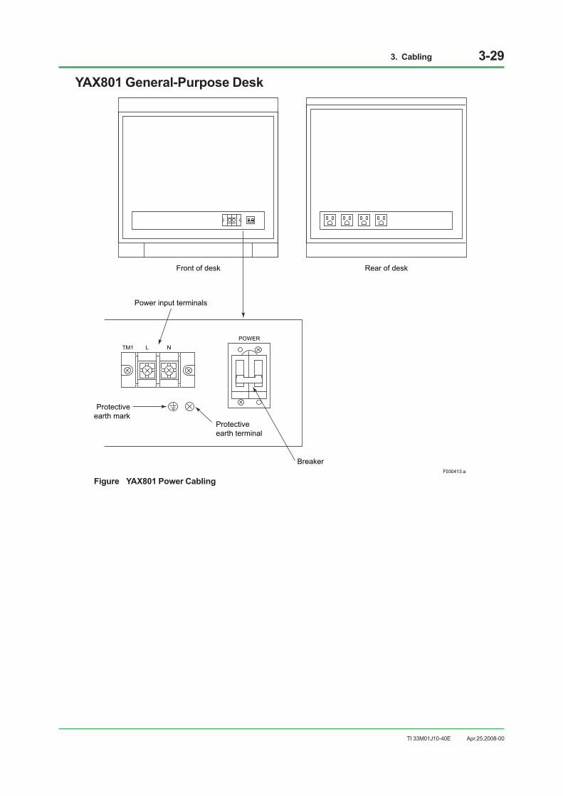
3. Cabling 3-29
TI 33M01J10-40E
YAX801 General-Purpose Desk
F030413.ai
Front of desk
Protectiveearth terminal
Power input terminals
Breaker
Protectiveearth mark
Rear of desk
TM1POWER
L N
Figure YAX801 Power Cabling
Apr.25,2008-00
3. Cabling 3-30
TI 33M01J10-40E
3.5 Connecting Signal CableThe terminals or connectors of field control station I/O modules interface I/O signals from the field.
Process I/O Signal Connection• Power, Control Bus, and signal cables must be separately laid. Avoid laying them in parallel.
• The use of group-shielded twisted-pair cables is recommended for analog signal input specifically in order to prevent induction noise. A twisted-pair cable pitch of 50 mm or less should be used and the shielded cables must be grounded.
• The use of twisted-pair cables is also recommended for digital signals.
• The twisted-pair cable has the following advantages over a solid wire:
- More flexible for easy curving and cabling in limited spaces.
- With good contact and durable in using a solderless contact.
• Signal cables must be clamped so that their weight does not affect terminals.
• Use solderless lug or pressure clamp terminal contact when process I/O signals are connected with terminals.
Solderless Lug
IMPORTANT • The CENTUM VP system uses spring terminals for RIO signal and RIO bus connections.
• Use the solderless contact with an insulation covering.
• Use the solderless contact and crimp tools of the same make.
• Use correct-size crimp tools according to cable sizes.
• When the door is attached or detached for cable connection, be sure to then OFF the power of the main unit before connecting or disconnecting a cable.
Pressure Clamp Terminal
IMPORTANT • The CENTUM VP uses a pressure clamp terminal for signal connection of FIO.
• For cable connection with a sleeve attached, use a sleeve and a clamp tool from the same manufacturer.
• Use a clamp tool which suits the cable thickness.
• When the door is attached or detached for cable connection, be sure to then OFF the power of the main unit before connecting or disconnecting a cable.
Apr.25,2008-00
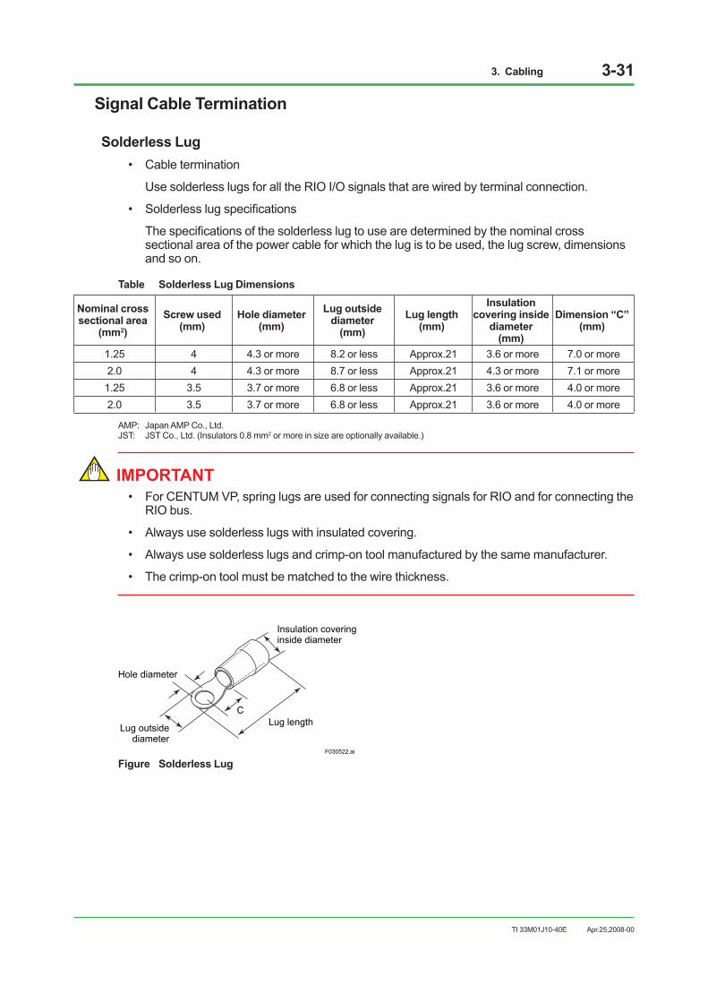
3. Cabling 3-31
TI 33M01J10-40E
Signal Cable Termination
Solderless Lug• Cable termination
Use solderless lugs for all the RIO I/O signals that are wired by terminal connection.
• Solderless lug specifications
The specifications of the solderless lug to use are determined by the nominal cross sectional area of the power cable for which the lug is to be used, the lug screw, dimensions and so on.
Table Solderless Lug Dimensions
Nominal crosssectional area
(mm2)Screw used
(mm)Hole diameter
(mm)Lug outside
diameter (mm)
Lug length (mm)
Insulation covering inside
diameter (mm)
Dimension “C”(mm)
1.25 4 4.3 or more 8.2 or less Approx.21 3.6 or more 7.0 or more2.0 4 4.3 or more 8.7 or less Approx.21 4.3 or more 7.1 or more1.25 3.5 3.7 or more 6.8 or less Approx.21 3.6 or more 4.0 or more2.0 3.5 3.7 or more 6.8 or less Approx.21 3.6 or more 4.0 or more
AMP: Japan AMP Co., Ltd.JST: JST Co., Ltd. (Insulators 0.8 mm2 or more in size are optionally available.)
IMPORTANT • For CENTUM VP, spring lugs are used for connecting signals for RIO and for connecting the
RIO bus.
• Always use solderless lugs with insulated covering.
• Always use solderless lugs and crimp-on tool manufactured by the same manufacturer.
• The crimp-on tool must be matched to the wire thickness.
F030522.ai
Insulation coveringinside diameter
Hole diameter
Lug outsidediameter
Lug lengthC
Figure Solderless Lug
Apr.25,2008-00

3. Cabling 3-32
TI 33M01J10-40E
Pressure Clamp Terminal (for Pressure Clamp Terminal Block)• Terminal processing
When connecting the process I/O signal to the pressure clamp terminal of FIO, strip the cable coating (without a sleeve) or attach a sleeve to the cable. The following shows the length of the coating stripped for cases when a sleeve is not used and when it is used.
Table Without a sleeve
Cable thickness (mm2) Length of coating stripped (mm) Remarks 0.5 to 2 (AWG20 to 14) 11 Other than below 1.25 to 2 (AWG16 to 14) 13 When connecting to ATC4S, ATC5S
Table With a sleeve
Cable thickness
(mm2)
When using a sleeve with an isolation cover When using a sleeve without an isolation cover Length of coating stripped
(mm)
Sleeve size Model No. of Weidmuller
Length of coating stripped
(mm)
Sleeve size Model No. of WeidmullerTotal
length Contact
section length Total length
(mm)
0.5 11 16 10 H0.5/16 11 10 H0.5/10 0.75 11 16 10 H0.75/16 11 10 H0.75/10 1 11 16 10 H1/16 11 10 H1/10 1.25 to 1.5 11 16 10 H1.5/16 11 10 H1.5/10 1.25 to 1.5 13 18 12 H1.5/18D(*1) 13 12 H1.5/12(*1)
*1: When connecting to ATC4S, ATC5S
Pressure Clamp Terminal (for ARSM) For both signal line and power line of the Solid State Relay Board ARSM, pressure clamp terminals are used.
• Terminal processing When connecting the signal and power line to the pressure clamp terminal, strip the cable coating (without a sleeve) or attach a sleeve to the cable. The following shows the length of the coating stripped for cases when a sleeve is not used and when it is used.
Table Terminal treatment for pressure clamp terminal signal line
Cable thickness (mm2) Length of coating stripped (mm)
Inserting length of sleeve (mm)
Without sleeve 0.5 to 2 (AWG20 to 14) 8 – With sleeve 0.5 to 2 (AWG20 to 14) 8 8
Table Terminal treatment for pressure clamp terminal power line
Cable thickness (mm2) Length of coating stripped (mm)
Inserting length of sleeve (mm)
Without sleeve 0.5 to 2 (AWG20 to 14) 9 – With sleeve 0.5 to 1.5 (AWG20 to 16) 9 8
Apr.25,2008-00

3. Cabling 3-33
TI 33M01J10-40E
Connecting Signal Cables to Terminals (for FIO)
Connecting to Pressure-clamp Terminal1. Loosen the cable connecting terminal screw.2. Strip the cable coating (without a sleeve) or attach a sleeve to the cable, then insert the tip of
the cable into the connecting section of the pressure clamp terminal.3. Fasten the screw using the special tool (a screw driver conforming to the DIC 5264B
standard with a tip width of 0.6 mm and a shaft diameter of 3.5 mm) with a fastening torque of 0.5 N•m.
Terminal screwCable terminal
ATA4S-00 S1
F030507.ai
Figure Connecting Signal Cable to Terminal (for FIO)
IMPORTANT Do not use non-standard signal cable or sleeve; using them could cause improper connection. Be sure to remove the cable sheath just as much as specified, fit the sleeve, and clamp the cable firmly to the terminal.
Apr.25,2008-00
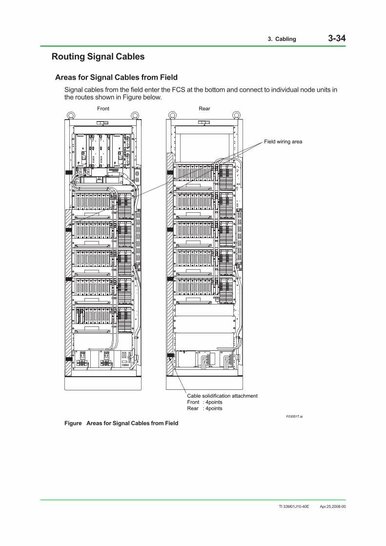
3. Cabling 3-34
TI 33M01J10-40E
Routing Signal Cables
Areas for Signal Cables from FieldSignal cables from the field enter the FCS at the bottom and connect to individual node units in the routes shown in Figure below.
F030517.ai
Front Rear
Field wiring area
Cable solidification attachmentFront : 4pointsRear : 4points
Figure Areas for Signal Cables from Field
Apr.25,2008-00
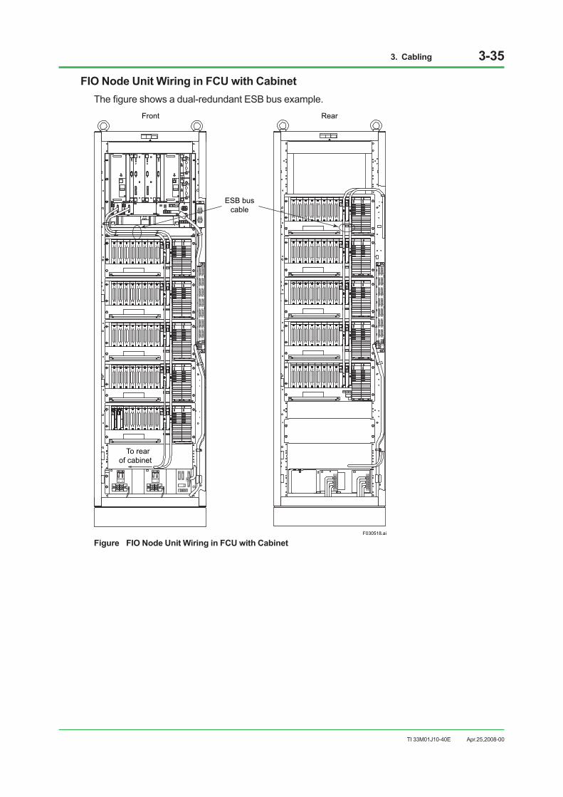
3. Cabling 3-35
TI 33M01J10-40E
FIO Node Unit Wiring in FCU with CabinetThe figure shows a dual-redundant ESB bus example.
F030518.ai
REVISIONU H1 H2
MODELAIP532
STYLE1 SIYOKOGAWA
ESB BusCN1
RCV
SND-L
SND-R
REVISIONU H1 H2
MODELAIP532
STYLE1 SIYOKOGAWA
ESB BusCN1
RCV
SND-L
SND-R
ESB buscable
To rear of cabinet
Front Rear
Figure FIO Node Unit Wiring in FCU with Cabinet
Apr.25,2008-00

3. Cabling 3-36
TI 33M01J10-40E
FIO Node Unit Wiring in I/O Expansion CabinetThe figure shows a dual-redundant ESB bus example, the ESB bus node units installed in the front of the cabinet and the terminal boards in the rear.Avoid using ESB bus cable with other cables and also avoid wiring its cable in parallel with others.
ESB bus cable
FG connecting screw (When usingisolation bushing)
Terminal board
Rear
F030519.ai
Front
To FCU
ESB bus cable
Figure FIO Node Unit Wiring in I/O Expansion Cabinet
Apr.25,2008-00

3. Cabling 3-37
TI 33M01J10-40E
AFF50S/AFF50D, ANR10S/ANR10D Wiring
IMPORTANT To reserve the ventilation for I/O module, the signal cable should not exceed the separator at the center of cable tray.
The following shows a duplexed ER bus example.
F030516.ai
Power
ANR10D
Magnified
Signal cable
Cable tray Power cable
ER bus cable
the ventilationopening
Signal Cable
To ensure the airflow route around I/O modulesthe signal cables over the tray should be kept awayfrom the ventilation opening of the tray.Therefore, the cables should not be laid over the ventilation openings of the tray.
Figure ANR10D Wiring
Apr.25,2008-00
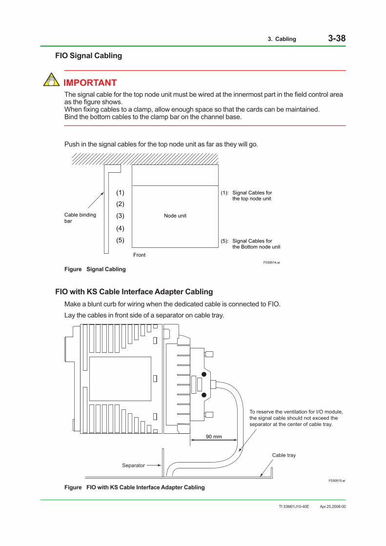
3. Cabling 3-38
TI 33M01J10-40E
FIO Signal Cabling
IMPORTANT The signal cable for the top node unit must be wired at the innermost part in the field control area as the figure shows. When fixing cables to a clamp, allow enough space so that the cards can be maintained. Bind the bottom cables to the clamp bar on the channel base.
Push in the signal cables for the top node unit as far as they will go.
F030514.ai
Front
Node unit
(1)
(2)
(3)
(4)
(5)
(1): Signal Cables for the top node unit
(5): Signal Cables for the Bottom node unit
Cable bindingbar
Figure Signal Cabling
FIO with KS Cable Interface Adapter CablingMake a blunt curb for wiring when the dedicated cable is connected to FIO.Lay the cables in front side of a separator on cable tray.
F030515.ai
90 mm
Separator
Cable tray
To reserve the ventilation for I/O module, the signal cable should not exceed the separator at the center of cable tray.
Figure FIO with KS Cable Interface Adapter Cabling
Apr.25,2008-00

3. Cabling 3-39
TI 33M01J10-40E
Connecting Signal Cables to Terminals (for RIO)1. Open the terminal board cover.2. Loosen the terminal screws.3. Insert the tip of the cable’s solderless contact between the screw and the spring retainer,
and press the retainer to make a gap of about 2 mm between them.4. Insert the solderless contact further in the gap until the screw enters in the hole of the
solderless contact.5. Tighten the terminal screw.6. Close the terminal board cover.
F030501.ai
Initial state
Solderless contact clamped
Covers
Cross section
ScrewSpring retainer
Screw loosened
Approx. 2 mm
Solderlesscontact
Solderless contact inserted
Solderless contacttentatively held in position
Figure Connecting Signal Cables to Terminals (Example: multiplexer module)
IMPORTANT • When connecting solderless lug, be sure to clamp its ring only.
• Using non-standard solderless lug may crush its sleeve, causing a connection failure.
F030502.ai
Correct clamping Incorrect clamping
Solderless lug
Sleeve
Ring
Figure Connect Clamping of Solderless Lug
Apr.25,2008-00
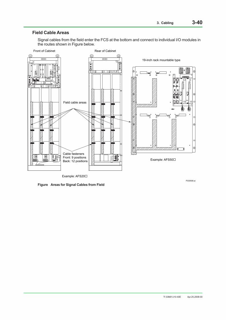
3. Cabling 3-40
TI 33M01J10-40E
Field Cable AreasSignal cables from the field enter the FCS at the bottom and connect to individual I/O modules in the routes shown in Figure below.
OKOK
Front of Cabinet Rear of Cabinet
19-inch rack mountable type
F030508.ai
Field cable areas
Cable fastenersFront: 9 positionsBack: 12 positions
Example: AFS20
Example: AFS50
Figure Areas for Signal Cables from Field
Apr.25,2008-00
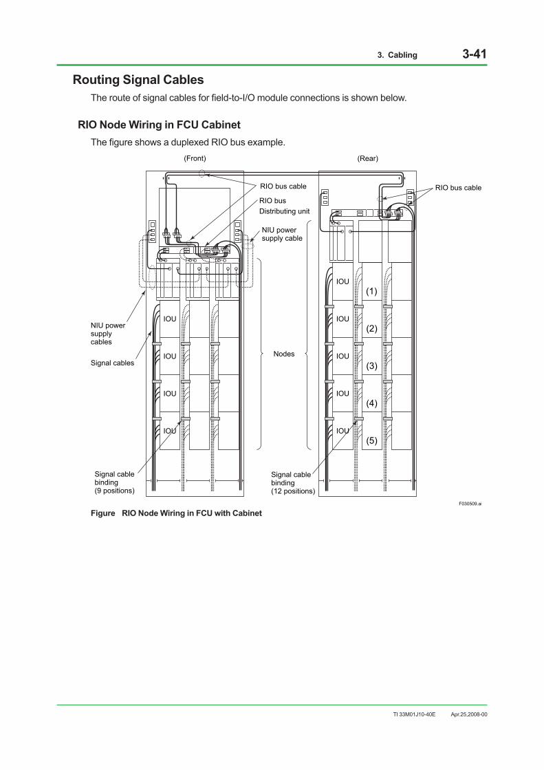
3. Cabling 3-41
TI 33M01J10-40E
Routing Signal CablesThe route of signal cables for field-to-I/O module connections is shown below.
RIO Node Wiring in FCU CabinetThe figure shows a duplexed RIO bus example.
(Front) (Rear)
IOU
IOU
IOU
IOU
IOU
IOU
IOU
IOU
IOU
(1)
(2)
(3)
(4)
(5)
F030509.ai
Nodes
Signal cablebinding(12 positions)
Signal cablebinding(9 positions)
NIU powersupply cable
RIO bus Distributing unit
NIU powersupplycables
Signal cables
RIO bus cable RIO bus cable
Figure RIO Node Wiring in FCU with Cabinet
Apr.25,2008-00

3. Cabling 3-42
TI 33M01J10-40E
RIO Node Wiring in I/O Expansion CabinetThe figure shows a duplexed RIO bus example.
IOU
IOU
IOU
IOU
IOU
IOU
IOU
IOU
IOU
IOU
F030511.ai
Nodes
Signal cablebinding(12 positions)
Cabinetinstallationtype NIU
Signal cables
Signal cablebinding(12 positions)
RIO bus distributing unit RIO bus cablesRIO bus cables
NIU power supply cablesNIU
powersupplycables
Figure RIO Node Wiring in I/O Expansion Cabinet
Apr.25,2008-00
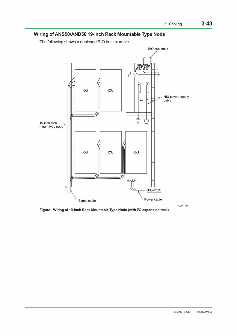
3. Cabling 3-43
TI 33M01J10-40E
Wiring of ANS50/AND50 19-inch Rack Mountable Type NodeThe following shows a duplexed RIO bus example.
IOUIOU
IOUIOU IOU
POWER
F030513.ai
19-inch rack mount type node
Signal cable
RIO bus cable
Power cable
NIU power supplycable
Figure Wiring of 19-inch Rack Mountable Type Node (with I/O expansion rack)
Apr.25,2008-00
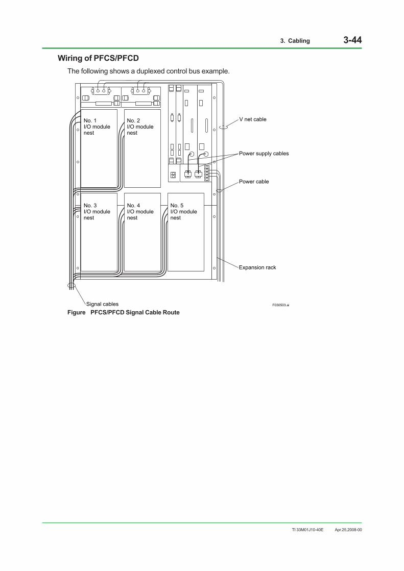
3. Cabling 3-44
TI 33M01J10-40E
Wiring of PFCS/PFCDThe following shows a duplexed control bus example.
Power supply cables
Expansion rack
Signal cables F030503.ai
No. 1 I/O module nest
No. 2 I/O module nest
No. 3 I/O module nest
No. 4 I/O module nest
No. 5 I/O module nest
V net cable
Power cable
Figure PFCS/PFCD Signal Cable Route
Apr.25,2008-00
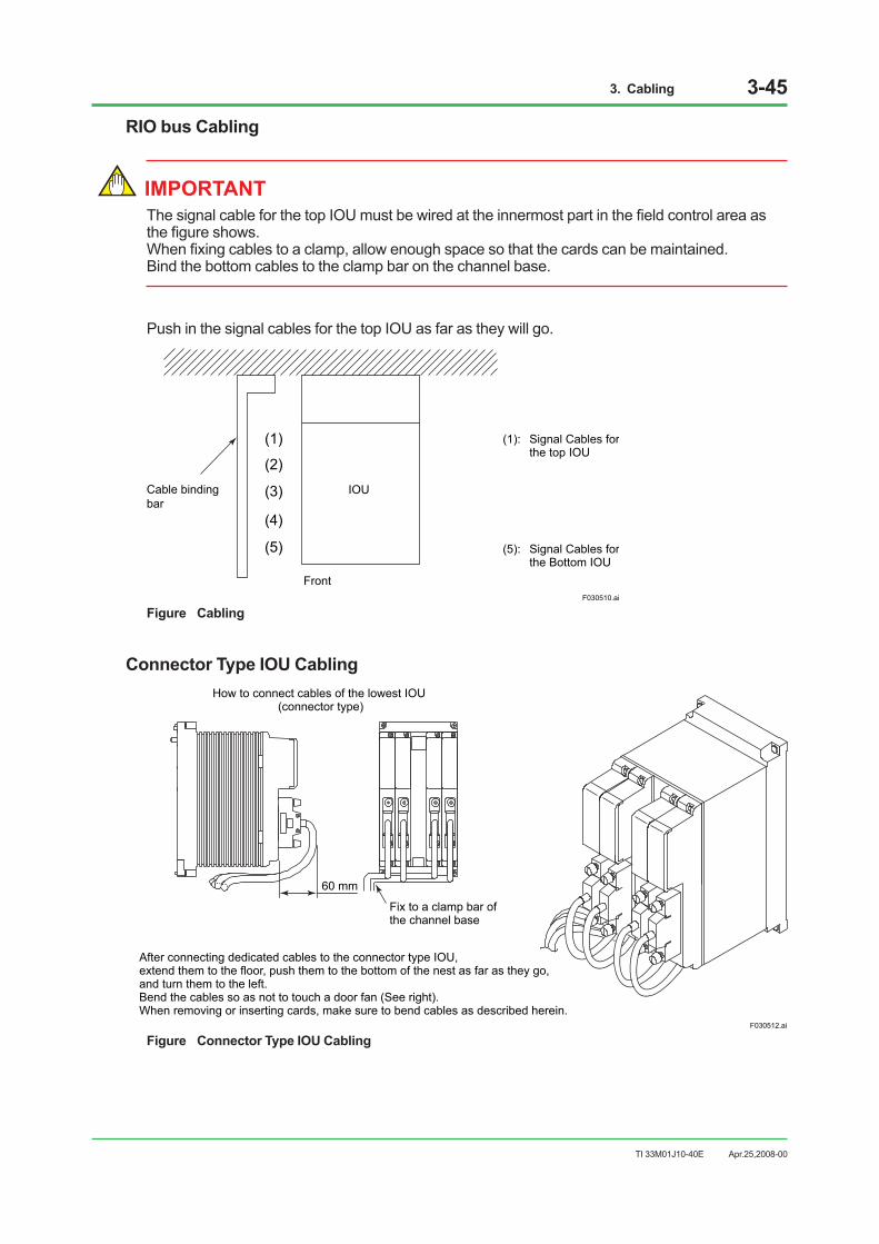
3. Cabling 3-45
TI 33M01J10-40E
RIO bus Cabling
IMPORTANT The signal cable for the top IOU must be wired at the innermost part in the field control area as the figure shows. When fixing cables to a clamp, allow enough space so that the cards can be maintained. Bind the bottom cables to the clamp bar on the channel base.
Push in the signal cables for the top IOU as far as they will go.
F030510.ai
Front
IOU
(1)
(2)
(3)
(4)
(5)
(1): Signal Cables for the top IOU
(5): Signal Cables for the Bottom IOU
Cable bindingbar
Figure Cabling
Connector Type IOU CablingHow to connect cables of the lowest IOU
(connector type)
F030512.ai
60 mm
Fix to a clamp bar of the channel base
After connecting dedicated cables to the connector type IOU, extend them to the floor, push them to the bottom of the nest as far as they go, and turn them to the left. Bend the cables so as not to touch a door fan (See right). When removing or inserting cards, make sure to bend cables as described herein.
Figure Connector Type IOU Cabling
Apr.25,2008-00
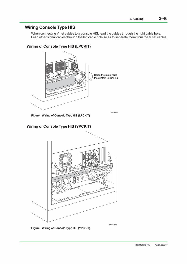
3. Cabling 3-46
TI 33M01J10-40E
Wiring Console Type HISWhen connecting V net cables to a console HIS, lead the cables through the right cable hole. Lead other signal cables through the left cable hole so as to separate them from the V net cables.
Wiring of Console Type HIS (LPCKIT)
F030521.ai
Raise the plate whilethe system is running
Figure Wiring of Console Type HIS (LPCKIT)
Wiring of Console Type HIS (YPCKIT)
F030523.ai
Figure Wiring of Console Type HIS (YPCKIT)
Apr.25,2008-00

3. Cabling 3-47
TI 33M01J10-40E
Modifying the Cabinet Bottom Plates for Cable WiringCables are passed through the holes in the bottom plates of the cabinet. The diameters of these holes can be changed to match the diameter of the cables. There are four bottom plates each at the front and rear of AF20/ACB21 specifically for signal cable wiring. There are three bottom plates each at the front and rear of AF40/ACB41 specifically for signal cable wiring.
F030504.ai
Bottom plates
Figure Bottom Plates of AF20/ACB21
Apr.25,2008-00

3. Cabling 3-48
TI 33M01J10-40E
To modify the bottom plates, follow these steps.1. Remove the bottom plate to be modified.
F030505.ai
Bottom plate
Screw
Cabinet
Figure Removing the Bottom Plate
2. Turn the bottom plate upside down so that the bottom faces upwards.3. Use a wire cutter or another appropriate tool to remove sections of the bottom plate so that
a hole large enough for the cable to pass through is made. Do not cut the sponge pad on the reverse side of the plate.
4. Cut and remove the area protective padding approximately 20 mm inside the opening made in the preceding step.
5. Turn the rim of the protective padding (width: 320 mm) inside out. This will protect the cable from the rough edges of the plate. The sponge pad has an adhesive surface. Peel the paper from the surface and stick the sponge pad to the plate.
F030506.ai
Cut the bottom plate
Cut off a part of the sponge pad
Turn over thesponge pad
Bottom plate
Sponge pad Sponge pad Sponge pad
Figure Modifying the Bottom Plate
6. Replace the bottom plate.
Apr.25,2008-00

3. Cabling 3-49
TI 33M01J10-40E
3.6 Connecting Signal Cables with Fieldnetwork I/O (FIO)
This section describes the signal connections with Fieldnetwork I/O (FIO) used on the AFS30S/AFS30D, AFG30S/AFG30D, AFS40S/AFS40D, AFG40S/AFG40D, or AFF50S/AFF50D.
3.6.1 Combination of Fieldnetwork I/O (FIO) and Terminal Blocks
A pressure clamp terminal block or KS cable (also called a “Yokogawa-specific cable”) interface adapter is available for field-wiring, or an MIL cable provided by the user may be used.
SEE ALSO For the terminal arrangement of the pressure clamp terminals and terminal board, and the pin arrangement of the
MIL connector, refer to “Field Connection Specifications (for FIO)” (GS 33M50H10-40E).
Apr.25,2008-00

3. Cabling 3-50
TI 33M01J10-40E
MIL connector
MIL cable
Pressure clamp terminal
KS cable interface adapterYokogawa-specificcable
Terminal block
I/O module
F030601.ai
Figure FIO Terminals
Apr.25,2008-00
3. Cabling 3-51
TI 33M01J10-40E
3.6.2 List of Signal Cables for Connection with FIO The following table shows the list of signal cables connections with FIO.
Table Signal Cables for Connection with FIO (1/3)
Module Name I/O channels per Module
Connection Signal Pressure
Clamp Terminal
Yokogawa- specific
Cable (*1) MIL
Cable
Analog I/O Modules AAI141 Analog Input Module (4 to 20 mA, Non-Isolated) 16 x x x AAV141 Analog Input Module (1 to 5 V, Non-Isolated) 16 x x x AAV142 Analog Input Module (-10 to +10 V, Non-Isolated) 16 x x x
AAI841 Analog I/O Module (4 to 20 mA Input, 4 to 20 mA Output, Non-Isolated) 8 input/8 output x x x
AAB841 Analog I/O Module (1 to 5 V Input, 4 to 20 mA Output, Non-Isolated) 8 input/8 output x x x
AAV542 Analog Output Module (-10 to +10 V, Non-Isolated) 16 x x x
AAI143 Analog Input Module (4 to 20 mA, Isolated) 16 x x x AAI543 Analog Output Module (4 to 20 mA, Isolated) 16 x x x AAV144 Analog Input Module (-10 to +10 V, Non-Isolated) 16 x x x
AAV544 Analog Output Module (-10 to +10 V, Non-Isolated) 16 x x x
AAT141 TC/mV Input Module (TC: R, J, K, E, T, B, S, N /mV: -100 to 150 mV, Isolated) 16 x – x(*3)
AAR181 RTD Input Module (RTD: Pt100 Ω, Isolated) 12 x – x
AAI135 Analog Input Module (4 to 20 mA, Isolated Channels) 8 x x x
AAI835 Analog I/O Module (4 to 20 mA, Isolated Channels) 4 input/4 output x x x
AAT145 TC/mV Input Module (TC: R, J, K, E, T, B, S, N /mV: -100 to 150 mV, Isolated Channels) 16 – x(*2) –
AAR145 RTD/POT Input Module (RTD: Pt100 Ω /POT: 0 to 10 kΩ, Isolated Channels) 16 – x(*2) –
AAP135 Pulse Input Module (Pulse Count, 0 to 10 kHz, Isolated Channels) 8 x x x
AAP149 Pulse Input Module for compatible PM1 (Pulse Count, 0 to 6 kHz, Non-Isolated) 16 – x –
AAP849 Pulse Input/Analog Output module for compatible PAC (Pulse Count input, 4 to 20 mA output, Non-Isolated) 8 input/8 output – x –
x : Can be connected.– : Cannot be connected.*1: Yokogawa-specific cable for connecting I/O Module and a terminal board, etc.*2: Can be connected directly with a Yokogawa-specific cable, without a terminal block.*3: When a MIL connector cable is connected, AAT141 modules can be used as mV-input modules.
Apr.25,2008-00

3. Cabling 3-52
TI 33M01J10-40E
Table Signal Cables for Connection with FIO (2/3)
Module Name I/O channels per Module
Connection Signal Pressure
Clamp Terminal
Yokogawa-specific
Cable (*1) MIL
Cable
Digital I/O Modules ADV151 Digital Input Module (24 V DC, 4.1 mA) 32 x x xADV551 Digital Output Module (24 V DC, 100 mA) 32 x x xADV141 Digital Input Module (100 to 120 V AC, 4.7 mA) 16 x x(*2) – ADV142 Digital Input Module (220 to 240 V AC, 6.2 mA/ch) 16 x x(*2) –
ADV157 Digital Input Module (24 V DC, 4.1 mA, Pressure Clamp Terminal Support Only) 32 x – –
ADV557 Digital Output Module (24 V DC, 100 mA, Pressure Clamp Terminal Support Only) 32 x – –
ADV161 Digital Input Module (24 V DC, 2.5 mA) 64 – x(*2) xADV561 Digital Output Module (24 V DC, 100 mA) 64 – x(*2) x
ADR541 Relay Output Module (24 to 110 V DC/100 to 240 V AC) 16 x x(*2) –
ADV859 Digital I/O Module for Compatible ST2 (Isolated Channels)
16 input /16 output – x(*2) –
ADV159 Digital Input Module for Compatible ST3 (Isolated Channels) 32 – x(*2) –
ADV559 Digital Output Module for Compatible ST4 (Isolated Channels) 32 – x(*2) –
ADV869 Digital I/O Module for Compatible ST5 (Common Minus Side Every 16-Channel)
32 input /32 output – x(*2) –
ADV169 Digital Input Module for Compatible ST6 (Common Minus Side Every 16-Channel) 64 – x(*2) –
ADV569 Digital Output Module for Compatible ST7 (Common Minus Side Every 16-Channel) 64 – x(*2) –
Communication Modules
ALR111 RS-232C Communication Module (1200 bps to 115.2 kbps) 2 port – x (D-SUB9
pin) (*2) –
ALR121 RS-422/RS-485 Communication Module (1200 bps to 115.2 kbps) 2 port –
x (M4 terminal block 5-
pole) (*2)
–
ALE111 Ethernet Communication Module (10 Mbps) 1 port – x (RJ-45) (*2) –
ALF111 Foundation Fieldbus (FF-H1) Communication Module (31.25 kbps) 4 port x x(*2) –
ALP111 PROFIBUS-DPV1 Communication Module 1 port – x(*2) –
x : Can be connected.– : Cannot be connected.*1: Yokogawa-specific cable for connecting I/O Module and a terminal board, etc.*2: Can be connected directly with a Yokogawa-specific cable, without a terminal block.
Apr.25,2008-00
3. Cabling 3-53
TI 33M01J10-40E
Table Signal Cables for Connection with FIO (3/3)
Module Name I/O channels per Module
Connection Signal Pressure
Clamp Terminal
Yokogawa-specific
Cable (*1) MIL
Cable
Analog I/O Modules with Built-in Barrier ASI133 Analog Input Module (4 to 20 mA, Isolated) 8 x – – ASI533 Analog Output Module (4 to 20 mA, Isolated) 8 x – –
AST143 TC/mV Input Module (TC: B, E, J, K, N, R, S, T / mV: -100 to 150 mV, -50 to 75 mV, Isolated) 16 x – –
ASR133 RTD/POT Input Module (RTD: Pt50, Pt100, Pt200, Pt500, Pt1000, Ni100, Ni200, Ni120 / POT: 0 to 10 kΩ,Isolated)
8 x – –
Digital I/O Modules with Built-in Barrier ASD143 Digital Input Module (NAMUR compatible, Isolated) 16 x – – ASD533 Digital Output Module (Isolated) 8 x – – Turbomachinery I/O Modules AGS813 Servo Module (Isolated) 12 – x(*4) – AGP813 High Speed Protection Module (Isolated) 26 – x(*4) –
x : Can be connected.– : Cannot be connected.*1: Yokogawa-specific cable for connecting I/O Module and a terminal board, etc.*4: Available cables are AKB337-M005, M007 and M010.
Apr.25,2008-00

3. Cabling 3-54
TI 33M01J10-40E
3.6.3 Connecting Signal Cables with FIO
Pressure Clamp Terminal
CH1CH2
CH16
Example of Analog module AAI141
Signal cable
F030602.ai
NC (not connected)
Figure I/O Module with Pressure Clamp Terminal
Dual-redundant Pressure Clamp Terminal
CH1CH2
CH16
Example of Analog module AAI141
NC (not connected)
Signal cable
F030603.ai
Figure I/O Module with Dual-redundant Pressure Clamp Terminal
Apr.25,2008-00

3. Cabling 3-55
TI 33M01J10-40E
KS Cable Interface Adapter
F030604.ai
Figure I/O Module with KS Cable Interface Adapter
The I/O modules are arranged in a dual-redundant configuration on the terminal board.
Connecting Signal Cables with Analog I/O ModuleSignal cables are connected to different terminals according to the devices to be connected as listed below:
Table Signal Names and I/O Signals of Analog I/O ModuleModel Name
Single Name I/O Signal
AAI141 AAI841 AAI143
INA 2-wire transmitter input + Current input -–
INB 2-wire transmitter input - Current input +
AAI135 AAI835 (*1)
INA 2-wire transmitter input + ––INB 2-wire transmitter input - Current input +
INC – Current input -
AAR181 (*2)
INA Resistance temperature detector input A– –INB Resistance temperature detector input B
INC Resistance temperature detector input B
AAR145 INA Resistance temperature detector input A Potentiometer input, 100%
–INB Resistance temperature detector input B Potentiometer input, 0% INC Resistance temperature detector input B Potentiometer input, variable
AAP135 INA 2-wire power supply source – 3-wire power supply
source INB 2-wire power supply signal 2-wire voltage, contact + 3-wire power supply + INC – 2-wire voltage, contact - 3-wire power supply -
is channel number.*1: If the power to models AAI141, AAI841, AAI135 and AAI835 is off or abnormal, the current input loop is in the open state. Do not use current signals with other receiving devices. When in use, also use an external receiver resistance in the voltage mode (Shunt resistant module part no. A1080RZ 250 ohm).*2: Wiring resistance for A and C must be identical.
Apr.25,2008-00
3. Cabling 3-56
TI 33M01J10-40E
Connecting Signal Cables with Pulse Input Module AAP135 The AAP135 receives contact ON/OFF, voltage pulse and current pulse. Refer to the figures below for details on how to connect signal cables since the items to be set by the system generation builder depend on the input pulse types.
When Receiving No-Voltage Contact Signals (1)For the relay contacts or transistor contacts, connect as follows.Pulse input frequency should be 0 to 800 Hz. Max. frequency differs due to the wiring effect, etc.
AAP135
SW1RL
SW2FIL
12 V DC/24 V DC pull-up resistorINA
INB
INC
Transmitter
F030605.ai
(SW1: OFF, SW2: ON for relay contact if necessary)
Setting Items by the system generation builder SW1 (RL) : OFF (No terminating resisror) SW2 (FIL) : ON if necessary (*1)
Figure No-Voltage contact Input (1)
When Receiving No-Voltage Contact Signals (2)Carry out connection as follows if a current is needed to flow to the relay contacts or transistor contacts.When receiving transistor contact signal of more than 800 Hz frequency, connect as follows.
TransmitterAAP135
(1 k ohm)RL
SW2FIL
12 V DC/24 V DCINA
INB
INC
(SW1: ON, SW2: ON for relay contact if necessary)
Setting Items by the system generation builder SW1 (RL) : 1 k ohm SW2 (FIL) : ON when necessary (*1)
SW1
F030606.ai
Figure No-Voltage contact Input (2)
*1: When there is a chattering noise at a mechanical relay, set the SW2 to ON to eliminate the noise.
Apr.25,2008-00

3. Cabling 3-57
TI 33M01J10-40E
When Receiving Voltage Pulse Signals
SW1RL
SW2FIL
12 V DC/24 V DCINA
INB
INC
Transmitter
(SW1: OFF, SW2: OFF)
Setting Items the system generation builder SW1 (RL) : OFF (No terminating resistor) SW2 (FIL) : OFF
+
-
F030607.ai
AAP135
Figure Voltage Pulse Input
When Receiving Current Pulse By Using the Internal Power to Drive the Transmitter (2-wire power supply type)
Transmitter
SW1RL
SW2FIL
12 V DC/24 V DCINA
INB
INC
(SW1: ON, RL selection, RL=200 ohm, 500 ohm, 1 k ohm, SW2: OFF)
Setting Items the system generation builder SW1 (RL) : Select the value of RL resistance SW2 (FIL) : OFF
F030608.ai
AAP135
Figure 2-Wire Power Supply Type
This method supplies power to the transmitter, and receives the transmitter output signals as the current pulse signals. By using the input load resistance (select from None, 200 ohm, 500 ohm, 1 k ohm), the current signal is converted to the voltage level pulse and receives it.
When Receiving Voltage Pulse By Using the Internal Power to Drive the Transmitter (3-wire power supply type)
SW1RL
SW2FIL
12 V DC/24 V DCINA
INB
INC
Transmitter
(SW1: OFF, SW2: OFF)
Setting Items the system generation builder SW1 (RL) : OFF (No terminating resistor) SW2 (FIL) : OFF
F030609.ai
AAP135
Figure 3-Wire Power Supply Type
Apr.25,2008-00

3. Cabling 3-58
TI 33M01J10-40E
Connecting Terminal Board with FIOThe I/O module equipped with a KS cable interface adapter can be connected to the terminal board using a Yokogawa-specific cable. Field signals are connected using the terminal board.
F030610.ai
ANB10D
AEA4D
Figure Example of Terminal Board Connection with Dual-redundant I/O Module
SEE ALSO For details of the KS cable interface adapter model and the cable model, refer to “Field Connection Specifications
(for FIO)” (GS 33M50H10-40E).
Apr.25,2008-00

3. Cabling 3-59
TI 33M01J10-40E
Connecting Relay Board with Digital I/O ModuleAn example of the connection of the mechanical relay board ARM55D with the Digital I/O Module ADV551 is shown below.
CN1
F030611.ai
Connection with FG
ADV551+ATD5A adapter
Yokogawa-specific cable AKB331
ARM55D
Figure Example of Relay Board Connection with FIO
Apr.25,2008-00

3. Cabling 3-60
TI 33M01J10-40E
3.6.4 Implementation and Cable Connection of Fieldbus Communication Module ALF111
This section describes the implementation and cable connection of the Foundation Fieldbus Communication Module ALF111.Foundation fieldbus H1 (Low Speed Voltage Mode) is called Foundation fieldbus, Fieldbus, H1 Fieldbus, FF, or FF-H1 in this manual.
Example of Implementation of Fieldbus Communication Module ALF111
To connect Fieldbus using the ALF111, the power supply unit for the Fieldbus must be prepared as shown below.The example of the implementation and the wiring of the ALF111 is shown below. For the implementation of the ALF111 and the relevant devices, follow the implementation conditions for the devices. 1 U (unit) = 44.45 mm.
F030612.ai
+CH1
CH2
CH3
CH4
–+–+–+–
+–+–+–+–
+–+–
24 V DCOUT
READY
TN1
+–+–
24 V DCOUT
READY
TN1
+–+–
24 V DCOUT
READY
TN1
+–+–
24 V DCOUT
READY
TN1
UL
UL
4U
5U
1U
4U
3U
PW60
ESB bus
Primarypower distribution unit
FG (When usingisolation bushing)
To MAIN PDB
End Plate (both ends)
MTL5995(Power supply unit for Fieldbus) +
ALF111
ALF111+ATF9S
AKB336(20PIN-20PIN)
AEP9D
AEF9D
To Field device
19-inch rack
FG(When using isolation bushing)
3U(*1)
3U (*1)
3U (*2)
MTLMS010 (spacer)
*1: Reserve a space of 3U for heat radiation.*2: Reserve a space of 3U for heat radiation and wiring.
Figure Example of ALF111 Implementation
Apr.25,2008-00
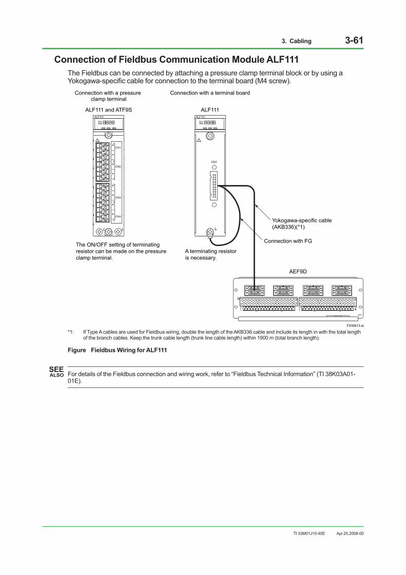
3. Cabling 3-61
TI 33M01J10-40E
Connection of Fieldbus Communication Module ALF111The Fieldbus can be connected by attaching a pressure clamp terminal block or by using a Yokogawa-specific cable for connection to the terminal board (M4 screw).
ALF111
CN1
AEF9D
ALF111 and ATF9S
The ON/OFF setting of terminating resistor can be made on the pressure clamp terminal.
A terminating resistor is necessary.
Yokogawa-specific cable (AKB336)(*1)
ALF111
Connection with a pressure clamp terminal
Connection with a terminal board
Connection with FG
F030613.ai
UL
UL
+CH1
CH2
CH3
CH4
–+–+–+–
+–+–+–+–
ALF111RCVSND
RCVSND
*1: If Type A cables are used for Fieldbus wiring, double the length of the AKB336 cable and include its length in with the total length of the branch cables. Keep the trunk cable length (trunk line cable length) within 1900 m (total branch length).
Figure Fieldbus Wiring for ALF111
SEE ALSO For details of the Fieldbus connection and wiring work, refer to “Fieldbus Technical Information” (TI 38K03A01-
01E).
Apr.25,2008-00
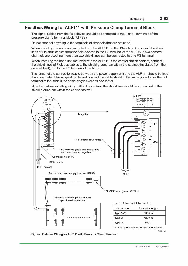
3. Cabling 3-62
TI 33M01J10-40E
Fieldbus Wiring for ALF111 with Pressure Clamp Terminal BlockThe signal cables from the field device should be connected to the + and - terminals of the pressure clamp terminal block (ATF9S).Do not connect anything to the terminals of channels that are not used.When installing the node unit mounted with the ALF111 on the 19-inch rack, connect the shield lines of Fieldbus cables from the field devices to the FG terminal of the ATF9S. If two or more channels are used, no more than two shield lines can be connected to one FG terminal. When installing the node unit mounted with the ALF111 in the control station cabinet, connect the shield lines of Fieldbus cables to the shield ground bar within the cabinet (insulated from the cabinet itself), not to the FG terminal of the ATF9S.The length of the connection cable between the power supply unit and the ALF111 should be less than one meter. Use a type A cable and connect the cable shield to the same potential as the FG terminal of the node if the cable length exceeds one meter.Note that, when installing wiring within the cabinet, the shield line should be connected to the shield ground bar within the cabinet as well.
+CH1
CH2
CH3
CH4
–+–+–+–
+–+–+–+–
ALF111RCVSND
+CH1
CH2
-+-+-+-
ALF111ALF111
F030614.ai
RCVSND
STATUS ACT DX
1 2 3 41 2 3 4
Secondary power supply bus unit AEP9D
Connection with FG
To FF devices
Fieldbus power supply MTL5995 (purchased separately)
24 V DC input (from PW60)
Use the following fieldbus cables:
*1: It is recommended to use Type A cable.
Cable type
Type A (*1)
Type B
Type D
Total wire length
1900 m
1200 m
200 m
To Fieldbus power supply
Magnified
FF-H1
FG terminal (Max. two shield lines can be connected together.)
FF-H1 cable
Figure Fieldbus Wiring for ALF111 with Pressure Clamp Terminal
Apr.25,2008-00

3. Cabling 3-63
TI 33M01J10-40E
Fieldbus Wiring for ALF111 with Terminal Board
F030615.ai
To ALF111
Terminal Board AEF9D
ALF111
CN1
ALF111RCVSND
Yokogawa-specific
cableAKB336
Connectionwith FG
TM1
Terminal Board AEF9D
UL
UL
UL
1+ 1- 2+ 2- 3+ 3- 4+ 4- NCNC1+ 1- 2+ 2- 3+ 3- 4+ 4-
When using the MTL5995 as a Fieldbus power supply, make ON/OF setting of the terminator on the Fieldbus power supply.When using a Fieldbus power supply without a built-in terminator, the terminator (YCB138) can be attached on the terminal board.To configure dual-redundant ALF111 on the terminal board (AFE9D), mount a pair of terminators (YCB138) to each empty port as well. FF-H1 cable
To FF devices
To Fieldbus power supply
Cabinet internal shield ground bar (isolated from the cabinet with an insulated board)
Secondary power supply bus unit AEP9D
Fieldbus power supply MTL5995 (purchased separately)
Use the following fieldbus cables:
*1: It is recommended to use Type A cable.
Cable type
Type A (*1)
Type B
Type D
Total wire length
1900 m
1200 m
200 m
Magnified
24 V DC input (from PW60)
To ALF111(to configure dual-redundant)
Figure Fieldbus Wiring for ALF111 with Terminal Board
Apr.25,2008-00

3. Cabling 3-64
TI 33M01J10-40E
Installation of Terminator to Terminal Board AEF9DMake sure to install a terminator (YCB138) if the ALF111 (terminal board AEF9D) terminates the network, in other words, if the network is not terminated by a terminator in the power supply unit.
F030616.ai
1+ 1- 2+ 2- 3+ 3- 4+ 4- N.C.
1+ 1- 2+ 2- 3+ 3- 4+ 4- N.C.
Terminator (YCB138)To FF devices
Terminal Board AEF9D
Figure Installation of Terminator to Terminal Board AEF9D
IMPORTANT In the following condition, the vacant port should be terminated with a pair of terminators:The AEF9D terminal board is used, the ALF111 is in a dual-redundant configuration, and any of the four ports is vacant.
Apr.25,2008-00

3. Cabling 3-65
TI 33M01J10-40E
3.7 Connecting Signal Cables with Remote I/O (RIO)
This section describes the signal connections with Remote I/O (RIO) used on the AFS10S/AFS10D, AFG10S/AFG10D, AFS20S/AFS20D, AFG20S/AFG20D, or PFCS/PFCD.
3.7.1 I/O Module Nests I/O Modules Nests are available in the following types:
• AMN11: Nest for Analog I/O Modules
• AMN12: High-Speed Nest for Analog I/O Modules (for AF10 and AF20)
• AMN21: Nest for Relay I/O Modules
• AMN31: Nest for Terminal-type I/O Modules
• AMN32: Nest for Connector-type I/O Modules
• AMN33: Nest for Communication Modules
• AMN34: Nest for Multipoint Control Analog I/O Modules
• AMN51: Nest for Communication Cards and Ethernet Communication Modules (for PFC only)
• AMN52: Nest for Profibus Communication Module (in PFC only)
F030730.ai
Multiplexer Modules orDigital I/O Modules(Connector Type)
ProfibusCommunication Modules
CommunicationModules
Multipoint ControlAnalog I/O Modules
CommunicationCards
Analog I/O Module Multiplexer Modules orDigital I/O Modules(Terminal Type)
Nest for Connector-typeI/O Modules(AMN32)
Relay I/O Module
Nest for CommunicationModules(AMN33)
Nest for Multipoint ControlAnalog I/O Modules(AMN34)
Nest for Communication Cardsand Ethernet Communication Modules (AMN51)
Nest for Profibus Communication Modules(AMN52)
Nest for Analog I/OModules(AMN11, AMN12)
Nest for Terminal-type I/OModules(AMN31)
Nest for Relay I/OModules(AMN21)
Figure I/O Module Nest Configuration
Apr.25,2008-00

3. Cabling 3-66
TI 33M01J10-40E
3.7.2 Signal Cables for Connection with RIOThe following table lists the signal cables for connection with RIO.
Table Signal Cables for Connection with RIO
Signal Type Model Module Type I/O Points Per Module
Signal Connection
Analog I/O Modules
AAM10 Current/Voltage Input Module (Simplified Type) 1
Terminals
AAM11 Current/Voltage Input Module 1 AAM11B Current/Voltage Input Module (supports BRAIN) 1 AAM21 mV, Thermocouple, and RTD Input Module 1
AAM21J mV, Thermocouple and RTD Input Module (conforms to IEC 584-1995, IEC 751-1995) 1
APM11 Pulse Input Module 1 AAM50 Current Output Module 1 AAM51 Current/Voltage Output Module 1 AMC80 Multipoint Control Analog I/O Module 8 input/8 output Connector
Relay I/O Modules
ADM15R Relay Input Module 16
Terminals
ADM55R Relay Output Module 16
Multiplexer Modules
AMM12T Voltage Input Multiplexer Module 16 AMM22T Thermocouple Input Multiplexer Module 16 AMM32T RTD Input Multiplexer Module 16 AMM42T 2-Wire Transmitter Input Multiplexer Module 16 AMM52T Current Output Multiplexer Module 16
AMM22TJ Thermocouple Input Multiplexer Module (16 Points, Terminal Type, conforms to IEC 584-1995) 16
AMM32TJ RTD Input Multiplexer Module (16 Points, Terminal Type, conforms to IEC 751-1995) 15
AMM22M mV Input Multiplexer Module 16 AMM12C Voltage Input Multiplexer Module 16
Connector
AMM22C mV Input Multiplexer Module (16 Points, Connector Type) 16
AMM25C mV Input Multiplexer Module with Thermocouple Interface (15 Points, Connector Type, RJC Input port added) 15
AMM32C RTD Input Multiplexer Module (16 Points, Connector Type) 16
AMM32CJ RTD Input Multiplexer Module (16 Points, Connector Type, conforms to IEC 751-1995) 16
Digital I/O Modules
ADM11T Contact Input Module (16 Points, Terminal Type) 16
Terminals ADM12T Contact Input Module (32 Points, Terminal Type) 32 ADM51T Contact Output Module (16 Points, Terminal Type) 16 ADM52T Contact Output Module (32 Points, Terminal Type) 32 ADM11C Contact Input Module (16 Points, Connector Type) 16
Connector ADM12C Contact Input Module (32 Points, Connector Type) 32 ADM51C Contact Output Module (16 Points, Connector Type) 16 ADM52C Contact Output Module (32 Points, Connector Type) 32
Communication Modules
ACM11 RS-232C Communication Module 1ch ACM12 RS-422/RS-485 Communication Module 1ch
Terminals ACF11 Fieldbus Communication Module 1ch
Communication Cards
ACM21 RS-232C General-purpose Communication Card 1ch Connector ACM22 RS-422/RS-485 General-purpose Communication Card 1ch Terminals
ACM71 Ethernet Communication Module (for PFC) 1ch RJ-45 (10BASE-T) Connector
ACP71 Profibus Communication Module 1ch D-Sub 9 pin Connector
Apr.25,2008-00

3. Cabling 3-67
TI 33M01J10-40E
3.7.3 Connecting Signal Cables with Analog I/O ModulesSignal cables are connected to different terminals according to type of input and output signal as listed below:
Table Analog I/O Module Terminals and Connections
Module Terminal I/O signal
AAM10 AAM11
A 2-wire transmitter input + B 2-wire transmitter input - Current input + Voltage input + C Current input - Voltage input -A BRAIN transmitter input +
AAM11B B BRAIN transmitter input - Current input + Voltage input + C Current input - Voltage input -
AAM21 AAM21J
A Resistance temperature Potentiometer input 100% detector input A
B mV/thermocouple input + Resistance temperature Potentiometer input variable detector input B
C mV/thermocouple input - Resistance temperature Potentiometer input 0% detector input B
A 2-wire power supply source 3-wire power supply source APM11 B 2-wire voltage, contact + 2-wire power signal 3-wire power supply +
C 2-wire voltage, contact - 3-wire power supply -A Current output +
AAM50 B — — C Current output -A Current output + Voltage output +
AAM51 B — C Current output - Voltage output -
Apr.25,2008-00
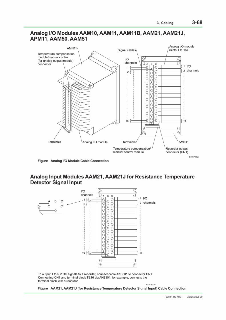
3. Cabling 3-68
TI 33M01J10-40E
Analog I/O Modules AAM10, AAM11, AAM11B, AAM21, AAM21J, APM11, AAM50, AAM51
BA C
F030701.ai
12
16
12
16
I/Ochannels
I/O
Terminals
AMN11
Temperature compensationmodule/manual control (for analog output module) connector
Analog I/O module Terminals
Temperature compensation/manual control module
Analog I/O module (slots 1 to 16)Signal cables
Recorder output connector (CN1)
AMN11
channels
Figure Analog I/O Module Cable Connection
Analog Input Modules AAM21, AAM21J for Resistance Temperature Detector Signal Input
F030702.ai
BA C12
16
12
16
I/Ochannels
I/OA B C
To output 1 to 5 V DC signals to a recorder, connect cable AKB301 to connector CN1. Connecting CN1 and terminal block TE16 via AKB301, for example, connects the terminal block with a recorder.
channels
Figure AAM21, AAM21J (for Resistance Temperature Detector Signal Input) Cable Connection
Apr.25,2008-00

3. Cabling 3-69
TI 33M01J10-40E
Connecting Signal Cables with Pulse Input Module APM11 The APM11 receives contact ON/OFF, voltage pulse and current pulse. Refer to the figures below for details on how to connect signal cables since the items to be set by the system generation builder depend on the input pulse types.
When Receiving No-Voltage Contact Signals (1)For the relay contacts or transistor contacts, connect as follows.Pulse input frequency should be 0 to 800 Hz. Max. frequency differs due to the wiring effect, etc.
+
-
OUTPUT
APM11
SW1RL
SW2FIL
12 V DC/24 V DCpull-up resistor
A
B
C
Transmitter
F030703.ai
(SW1: OFF, SW2: ON for relay contact if necessary)
Setting Items by the system generation builder SW1 (RL) : OFF (No terminating resisror) SW2 (FIL) : ON if necessary (*1)
Figure No-Voltage Input (1)
When Receiving No-Voltage Contact Signals (2)Carry out connection as follows if a current is needed to flow to the relay contacts or transistor contacts.When receiving transistor contact signal of more than 800 Hz frequency, connect as follows.
Transmitter
+
-
OUTPUT
APM11
(1 k ohm)RL
SW2FIL
12 V DC/ 24V DCA
B
C
(SW1: ON, SW2: ON for relay contact if necessary)
Setting Items by the system generation builder SW1 (RL) : 1 k ohm SW2 (FIL) : ON if necessary
SW1
F030704.ai
Figure No-Voltage Input (2)
*1: When there is a chattering noise at a mechanical relay, set the SW2 to ON to eliminate the noise.
Apr.25,2008-00

3. Cabling 3-70
TI 33M01J10-40E
When Receiving Voltage Pulse Signals
+
-
OUTPUTSW1RL
SW2FIL
12 V DC/24 V DCA
B
C
Transmitter
(SW1: OFF, SW2: OFF)
Setting Items by the system generation builder SW1 (RL) : OFF (No terminating resistor) SW2 (FIL) : OFF
+
-
F030705.ai
Figure Voltage Pulse Input
When Receiving Current Pulse By Using the Internal Power to Drive the Transmitter (2-wire power supply type)
Transmitter
+
-
OUTPUTSW1RL
SW2FIL
12 V DC/24 V DCA
B
C
(SW1: ON, RL selection, RL=200 ohm, 510 ohm, 1 k ohm, SW2: OFF)
Setting Items by the system generation builder SW1 (RL) : Select the value of RL resistance SW1 (FIL) : OFF
F030706.ai
Figure 2-Wire Power Supply Type
This method supplies power to the transmitter, and receives the transmitter output signals as the current pulse signals. By using the input load resistance (select from None,200 ohm, 510 ohm, 1 k ohm), the current signal is converted to the voltage level pulse and receives it.
When Receiving Voltage Pulse By Using the Internal Power to Drive the Transmitter (3-wire power supply type)
+
-
OUTPUTSW1RL
SW2FIL
12 V DC/24 V DCA
B
C
Transmitter
(SW1: OFF, SW2: OFF)
Setting Items by the system generation builder SW1 (RL) : OFF (No terminating resistor) SW2 (FIL) : OFF
F030707.ai
Figure 3-Wire Power Supply Type
Apr.25,2008-00

3. Cabling 3-71
TI 33M01J10-40E
Redundant AAM50/AAM51These modules output signals of 4 to 20 mA or 0 to 10 V. They may be made redundant when they are set in the current output mode. To make them redundant, two AAM50 or AAM51 modules must be installed in two adjacent slots beginning with an odd-number slot (1-2, 3-4, ....13-14, 15-16) and set to be redundant, and adjacent terminals A and C must be connected to check their outputs against each other as shown below. The AAM50 and AAM51 modules cannot be combined for redundancy.
F030708.ai
AAM51
AAM51
Other AAM module
Other AAM module
AMN11
3A
4A
3C
4C
3B
4B
AAM51 modules in slots 3 and 4 are made redundant in this example.
Figure Redundant Current Output Module AAM51
Apr.25,2008-00

3. Cabling 3-72
TI 33M01J10-40E
3.7.4 Connecting Signal Cables with Multipont Analog Control I/O Module AMC80
Connect the shield of the Yokogawa-specific cable to the shield terminal.
RDYDXOUT
YOKOGAWA YOKOGAWA
RDYDXOUT
F030709.ai
ShieldAMC80
Signal Cable(KS1)
AMN34
Figure AMC80 Signal Cable Connection
Apr.25,2008-00

3. Cabling 3-73
TI 33M01J10-40E
Connecting Signal Cables with MCM Terminal BoardTwo AMC80s can be set up in a dual-redundant configuration by connecting them to an MCM terminal board as shown in the figure below. When the AMC80 is used in a single configuration, one MCM terminal board is required for each AMC80.
IMPORTANT Do not set up AMC80s in the single mode when they are connected to a MCM terminal board in the dual-redundant configuration.
RDYDXOUT
YOKOGAWA YOKOGAWA
RDYDXOUT
F030710.ai
KS1 Cable
AMC80
MCM Terminal Board
To other converter
××××
× ××××
× ××××
× ××××
× ××××
× ××××
× ××××
× ××××
×
Figure Example of Dual-redundant AMC80 Configuration
Apr.25,2008-00

3. Cabling 3-74
TI 33M01J10-40E
3.7.5 Connecting Signal Cables with Relay I/O Modules
Relay Input Module ADM15R
C B A
RL
F030711.ai
16
12
A
B
C
Outputchannels
Terminal C not used
Figure Signal Cable Connection of Relay Input Module ADM15R
Relay Output Module ADM55R
C B A
A
B
C
A-C: Terminal A (closed when excited)B-C: Terminal B (closed when de-excited)
16
12
Outputchannels
F030712.ai
Figure Signal Cable Connection of Relay Output Module ADM55R
Apr.25,2008-00

3. Cabling 3-75
TI 33M01J10-40E
3.7.6 Connecting Signal Cables with Multiplexer Modules (Terminal Type)
Voltage Input, mV Input, Thermocouple Input, 2-wire Transmitter Input, Current Output Modules AMM12T, AMM22M, AMM22T, AMM22TJ, AMM42T, AMM52T.
Only one AMM42T or AMM52T can be installed in one nest.
B A B A
F030713.ai
AMN31
ModuleMultiplexer
TerminalsSignal cables
16
Not used12
-
++
Not used
16
12
I/Ochannels
-
-
+
Figure Multiplexer Module Signal Cable Connection
RTD Input Modules AMM32T, AMM32TJOnly one AMM32T or AMM32TJ can be installed in one nest.
B B A
F030714.ai
AMN31
MultiplexerModule
Terminal
Signal cables
16
12
I/Ochannels
Figure Signal Cable Connection of RTD Input Multiplexer Modules AAM32T, AAM32TJ
Apr.25,2008-00
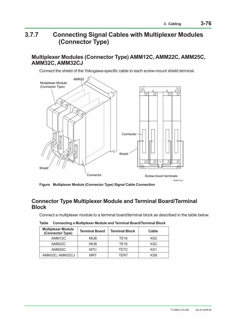
3. Cabling 3-76
TI 33M01J10-40E
3.7.7 Connecting Signal Cables with Multiplexer Modules (Connector Type)
Multiplexer Modules (Connector Type) AMM12C, AMM22C, AMM25C, AMM32C, AMM32CJ
Connect the shield of the Yokogawa-specific cable to each screw-mount shield terminal.
1 2 3 4
F030715.ai
AMN32
Shield
Connector
Connector
Shield
Screw-mount terminals
Multiplexer Module(Connector Type)
Figure Multiplexer Module (Connector Type) Signal Cable Connection
Connector Type Multiplexer Module and Terminal Board/Terminal Block
Connect a multiplexer module to a terminal board/terminal block as described in the table below.
Table Connecting a Multiplexer Module and Terminal Board/Terminal BlockMultiplexer Module (Connector Type) Terminal Board Terminal Block Cable
AMM12C MUB TE16 KS2 AMM22C MUB TE16 KS2 AMM25C MTC TETC KS1
AMM32C, AMM32CJ MRT TERT KS8
Apr.25,2008-00

3. Cabling 3-77
TI 33M01J10-40E
3.7.8 Connecting Signal Cables with Digital I/O Modules (Terminal Type)
16-Point Digital I/O Modules ADM11T, ADM51T
B A B A
F030716.ai
Empty12
16
Terminals
Empty
AMN31
Digital I/O Module
16
12
I/Ochannel
I/O contact
Signal cable
+ -
-
-+
+
Figure 16-Point Digital I/O Module Signal Cable Connection
32-Point Digital I/O Modules ADM12T, ADM52T
F030717.ai
12
1516
1718
3132
Terminals
AMN31
I/O contact
Channel common terminals 1 to 16
Channel common terminals 17 to 32
--
-
--
--
-
++
++
++
++
Digital I/OModule
Figure 32-Point Digital I/O Module Signal Cable Connection
Apr.25,2008-00

3. Cabling 3-78
TI 33M01J10-40E
3.7.9 Connecting Signal Cables with Digital I/O Modules (Connector Type)
Digital I/O Modules ADM11C, ADM12C, ADM51C, ADM52CConnect the shield of the Yokogawa-specific cable to each screw-mount shield terminal.
1 2 3 4
F030718.ai
AMN32
Shield
Connector
Connector
Shield
Screw-mount terminals
Digital I/O Module
Figure Connector-type Digital I/O Module Signal Cable Connection
Apr.25,2008-00

3. Cabling 3-79
TI 33M01J10-40E
3.7.10 Connecting Signal Cables with Communication Modules
RS-232C Communication Module ACM11
CN1 CN1
RDYRCVSND
YOKOGAWA YOKOGAWA
RDYRCVSND
F030719.ai
AMN33
Figure ACM11 Signal Cable Connection
Use modem cable KB3 and null modem cable KB4 with a D-sub 25-pin connector.
Table RS-232C Interface Connector Pin Positions
Pin position Code Signal Description 1 FG Frame Ground Maintenance grounding 2 SD Send Data Transmission data (output) 3 RD Receive Data Receiving data (input) 4 RS Request to Send Transmission request (output) 5 CS Clear to Send Ready for transmission (input) 6 DR Dataset Ready Dataset ready (input) 7 SG Signal Ground Signal common return 8 CD Carrier Detect Carrier detection (input) 20 ER Equipment Ready Data terminal ready (output)
IMPORTANT When the system is used in Europe, attach a clamp filter (ferrite core) complying with the EMC standard in order to use RS-232C. The parts number of the clamp filter is A1179MN.
Apr.25,2008-00
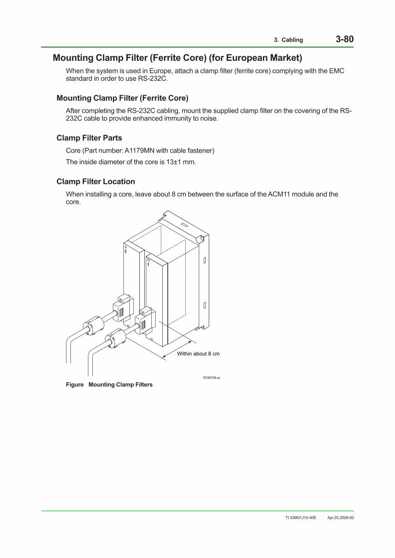
3. Cabling 3-80
TI 33M01J10-40E
Mounting Clamp Filter (Ferrite Core) (for European Market)When the system is used in Europe, attach a clamp filter (ferrite core) complying with the EMC standard in order to use RS-232C.
Mounting Clamp Filter (Ferrite Core)After completing the RS-232C cabling, mount the supplied clamp filter on the covering of the RS-232C cable to provide enhanced immunity to noise.
Clamp Filter PartsCore (Part number: A1179MN with cable fastener)The inside diameter of the core is 13±1 mm.
Clamp Filter LocationWhen installing a core, leave about 8 cm between the surface of the ACM11 module and the core.
F030720.ai
Within about 8 cm
Figure Mounting Clamp Filters
Apr.25,2008-00

3. Cabling 3-81
TI 33M01J10-40E
Structure of Clamp Filter and Mounting 1. Unlock the two core lock claws by hand, and the core will open about 150° and split into two
pieces as shown in the figure below.
F030721.ai
Lock Two Claws
Clamp with Cable FastenerCable FastenerRS-232C Cable
Core
Core Lock Claw
Cable Connector
Figure Structure of Clamp Filter and Mounting
2. Put the RS-232C cable into the cylindrical part of the opened core.3. Close the core with the RS-232C cable within it, and lock the clamp filter with two core lock
claws.4. Pass a cable fastener into either hole in the clamp filter and secure the RS-232C cable by
clamping the cable fastener over the cable coating.
IMPORTANT The clamp filter consists of a ferrite core. Avoid mechanical shocks to it such as by dropping it, and keep it within the temperature ranges during operation and storage.
Apr.25,2008-00

3. Cabling 3-82
TI 33M01J10-40E
RS-422/RS-485 Communication Module ACM12
RDYRCVSND
TX+
TX-RX+RX-SG
FG
TW1
RDYRCVSND
TX+
TX-RX+RX-SG
FG
TW1
RDYRCVSND
TW1
TX+
TX-
RX+
RX-
SG
FG
RDYRCVSND
TW1
TX+
TX-
RX\+
RX-
SG
FG
F030722.ai
AMN33
Figure ACM12 Signal Cable Connection
Table RS-422/RS-485 Interface Terminal Positions
Terminal Code Signal Name Description TX+ Send Data Transmission data (in-phase signals) TX- Send Data Transmission data (phase-reversal signals) RX+ Receive Data Receiving data (in-phase signals) RX- Receive Data Receiving data (phase-reversal signals) SG Signal Ground Signal grounding FG Frame Ground Protective grounding
Apr.25,2008-00

3. Cabling 3-83
TI 33M01J10-40E
RS-232C Communication Card ACM21
F030723.ai
AMN51
Figure ACM21 Signal Cable Connection
Use modem cable KB3 and null modem cable KB4 with a D-Sub 25-pin connector.
Table RS-232C Interface Connector Pin Positions
Pin Assign Signal Abbreviation Signal Name Description 1 FG Frame Ground Maintenance grounding 2 SD Send Data (output) Transmission data (output) 3 RD Receive Data Receiving data (input) 4 RS Request to Send (output) Transmission request (output) 5 CS Clear to Send Ready for transmission (input) 6 DR Dataset Ready (input) Dataset ready (input) 7 SG Signal Ground Signal common return 8 CD Carrier Detect (input) Carrier detection (input) 20 ER Equipment Ready (output) Data terminal ready (output)
Apr.25,2008-00
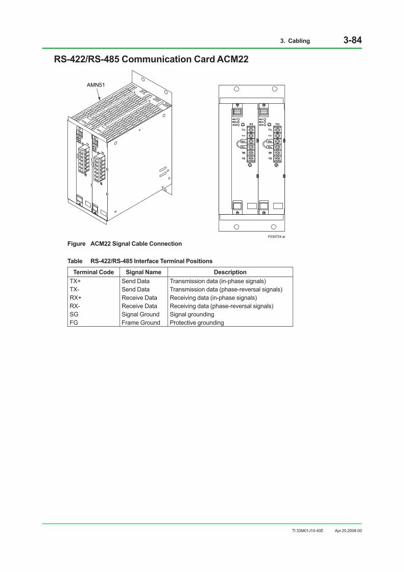
3. Cabling 3-84
TI 33M01J10-40E
RS-422/RS-485 Communication Card ACM22
F030724.ai
AMN51
Figure ACM22 Signal Cable Connection
Table RS-422/RS-485 Interface Terminal Positions
Terminal Code Signal Name Description TX+ Send Data Transmission data (in-phase signals) TX- Send Data Transmission data (phase-reversal signals) RX+ Receive Data Receiving data (in-phase signals) RX- Receive Data Receiving data (phase-reversal signals) SG Signal Ground Signal grounding FG Frame Ground Protective grounding
Apr.25,2008-00

3. Cabling 3-85
TI 33M01J10-40E
Ethernet Communication Module ACM71 (For PFC)
F030725.ai
CN1
CN1
CN1
CN1
AMN51
Figure Ethernet Communication Module ACM71
Use 10BASE-T, non-shielded, 100-ohm twisted-pair cables for Ethernet connections.
Table Pin Assignment of Ethernet Interface Connector (RJ-45)
Pin Signal Abbreviation Signal Name 1 TD+ Send Data (+) 2 TD- Send Data (-) 3 RD+ Receive Data (+) 4 – – 5 – – 6 RD- Receive Data (-) 7 – – 8 – –
Apr.25,2008-00

3. Cabling 3-86
TI 33M01J10-40E
3.7.11 Connecting the Fieldbus Cable and Handling the Shield Mesh for Fieldbus Communication Module ACF11
CN1
MAIN 1
CN1
RDYCTLRCV
RDYCTLRCVSND SND
TM1
+
-
NC
+
-
NC
TM1
+
-
NC
+
-
NC
MAIN 1
RDYCTLSNDRCV
$$
MAIN1
$$
NC
TW1
RDYCTLSNDRCV
$$
MAIN1
$$
NC
TW1
F030726.ai
AMN33
Figure Fieldbus Communication Module Signal Wiring Terminals
Connect field signals to the + and - signal terminals (marked 1 and 2 respectively).A clamp filter must be attached to the signal cable as shown.Connect a terminator to terminals 4 and 5.Do not connect anything to terminals marked NC (No Connection), i.e. terminals 3 and 6.
12
3
45
6
Clamp filter (A1179MN)
Terminator(YCB138)
F030727.ai
+-NC
Figure ACF11 Signal Wiring Terminals
SEE ALSO • For details of Fieldbus connection and wiring work, refer to “Fieldbus Technical Information” (TI 38K03A01-
01E).
• The clamp filter part number and method of attachment are the same as for that used in the ACM11 Communications Module. Mount it as close as possible to the terminals, as illustrated in the figure below.
There is a gap between the inside of the core and outside of the cable, so secure the cable by clamping the cable fastener over the cable coating.
Apr.25,2008-00

3. Cabling 3-87
TI 33M01J10-40E
Use a Type A cable for the connection between the ACF11 and the marshalling rack (shown in dotted box in the figure below), in which the shield of the cable from the field is connected to the ground terminal.Connect the shield of the Type A cable of the FCU side (inside the cabinet) to the cabinet internal ground bar. If it is necessary to separate the shield ground from the other ground, disconnect the wire between the cabinet internal shield ground bar and FCU ground bar, and ground them separately.
Arrestor etc.
ACF11
F030728.ai
FCU
10 ohms or less recommended or 100 ohms or less
When there is no arrester.
To ACF11
Type A cable
Type A cable
To AAM11, AAM21 modules etc.
To FCU ground bar
To AAM11, AAM21 modules etc.
To FCU ground bar
Ground bar for connecting wire to ground
Connection to ground bar
Type A cable shield connectionTerminator
Clamp filter(Mount it always, regardless of CE Mark regulation.)
Cabinet internal shield ground bar (With an insulated board)
Figure Connecting Fieldbus Cable with Fieldbus Communication Module ACF11
Apr.25,2008-00
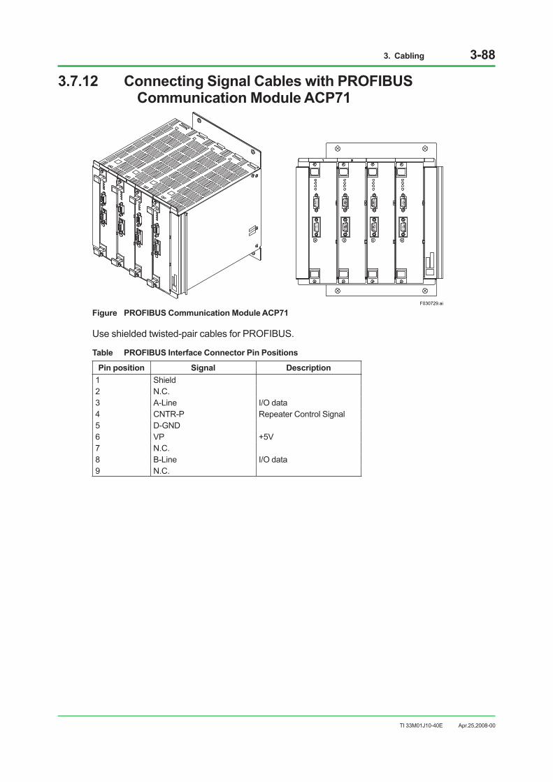
3. Cabling 3-88
TI 33M01J10-40E
3.7.12 Connecting Signal Cables with PROFIBUS Communication Module ACP71
F030729.ai
Figure PROFIBUS Communication Module ACP71
Use shielded twisted-pair cables for PROFIBUS.
Table PROFIBUS Interface Connector Pin Positions
Pin position Signal Description 1 Shield 2 N.C. 3 A-Line I/O data 4 CNTR-P Repeater Control Signal 5 D-GND 6 VP +5V 7 N.C. 8 B-Line I/O data 9 N.C.
Apr.25,2008-00
3. Cabling 3-89
TI 33M01J10-40E
3.8 Connecting Bus Cable
IMPORTANT 1. When the sheath of the control-bus cable is connected, there is a possibility that (ground
loop) currents will flow in the sheath. 2. Before connecting a V net splitter (N-type or BNC-type) to coaxial cable, use the following
method to drain static electricity: wear a wrist strap. If the cable is already connected to other stations, this is not necessary.
• Momentarily short the cable inner conductor to the outer sheath.
• Next connect the cable to the coupler.
V netThe following is an example of connecting a control bus.
• Attach a T-shaped plug to the BUS1 and BUS2 BNC connectors of the control bus interface card. Order the T-shaped plug separately.
• Connect V net cables (10BASE-2 cable: YCB141) to the BUS1 and BUS2 through previous station.
• Connect V net cables (10BASE-2) from the other side of the T-shaped plug to next station.
• When connecting V net cable (10BASE-5 cable: YCB111) to next station, place a connection unit (YCB147) between V net cable (YCB141) and V net cable (YCB111). Order a connection unit separately.
• When no next station is connected, attach YCB148 V net Terminator for 10BASE-2 cable and YCB118 for 10BASE-5 cable.
IMPORTANT In this document, 10BASE-5 and 10BASE-2, terminology of Ethernet, are use to describe the V net cables for easier understanding. Actually, V net is different from Ethernet. Yokogawa’s YCB111 and YCB141 cables should be used instead of 10BASE-5 and 10BASE-2 cables.
Apr.25,2008-00

3. Cabling 3-90
TI 33M01J10-40E
Connecting V net cables (10BASE-2)
F030801.ai
Bus2
Bus2
Bus1
Bus1
Bus1
Bus2
PRINTERRS232C-A
(COM2)
E X TRS232C-B
(COM1)SLOT1 SLOT2 SLOT3 SLOT4 SLOT5 SLOT6 SLOT7
Connector to next unit, or terminatorif end of bus.
PRINTERRS232C-A
(COM2)
E X TRS232C-B
(COM1)SLOT1 SLOT2 SLOT3 SLOT4 SLOT5 SLOT6 SLOT7
Console Type HIS(LPCKIT)
Rear of HIS
V net cable(10BASE-2)
BNC connector(Bus2 side)
BNC connector(Bus1 side)
Terminator
Dust proof cap
Control bus interface card
Tee connector
Front
Rear
BU
S1
BU
S2
RCV
SHD
RCV
SHD
VF701
Figure V net Cable (10BASE-2) Connection
Apr.25,2008-00
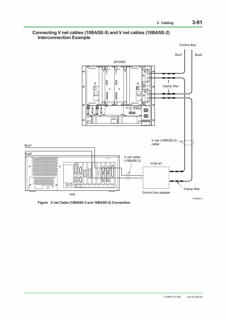
3. Cabling 3-91
TI 33M01J10-40E
Connecting V net cables (10BASE-5) and V net cables (10BASE-2) Interconnection Example
F030802.ai
PRINTERRS232C-A
(COM2)
E X TRS232C-B
(COM1)SLOT1 SLOT2 SLOT3 SLOT4 SLOT5 SLOT6 SLOT7
Control bus adapterHIS
Clamp filter
V net (10BASE-5)cable
V net cable (10BASE-2)
Clamp filter
AFS30D
Bus1 Bus2
Bus1
Bus2
Control Bus
YCB147
REVISIONU H1 H2
MODELAIP532
STYLE1 SIYOKOGAWA
ESB BusCN1
RCV
SND-L
SND-R
REVISIONU H1 H2
MODELAIP532
STYLE1 SIYOKOGAWA
ESB BusCN1
RCV
SND-L
SND-R
Figure V net Cable (10BASE-2 and 10BASE-5) Connection
Apr.25,2008-00
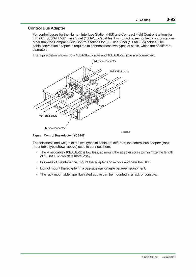
3. Cabling 3-92
TI 33M01J10-40E
Control Bus AdapterFor control buses for the Human Interface Station (HIS) and Compact Field Control Stations for FIO (AFF50S/AFF50D), use V net (10BASE-2) cables. For control buses for field control stations other than the Compact Field Control Stations for FIO, use V net (10BASE-5) cables. The cable conversion adapter is required to connect these two types of cable, which are of different diameters.The figure below shows how 10BASE-5 cable and 10BASE-2 cable are connected.
N type connector
BNC type connector
10BASE-2 cable
10BASE-5 cable
F030803.ai
Figure Control Bus Adapter (YCB147)
The thickness and weight of the two types of cable are different; the control bus adapter (rack mountable type shown above) used to connect them.
• The V net cable (10BASE-2) is low less, so mount the adapter so as to minimize the length of 10BASE-2 (which is more lossy).
• For ease of maintenance, mount the adapter above floor and near the HIS.
• Do not mount the adapter in a passageway or aisle between equipment.
• The rack mountable type illustrated above can be mounted in a rack or console.
Apr.25,2008-00

3. Cabling 3-93
TI 33M01J10-40E
Connecting V net cables (10BASE-5)
AFS30D
PFCD
Bus1 Bus2
Bus1 Bus2
F030804.ai
V net cables (10BASE-5)
Control Bus Coupler(Bus2)
Clamp filter
To next unit (Attach a terminator if no next unit is connected)
Figure V net Cable (10BASE-5) Connection
Apr.25,2008-00

3. Cabling 3-94
TI 33M01J10-40E
V net Coupler Installation (ACG10S)The V net couplers of desktop communication gateway can be attached in three ways depending on where bracket is installed, as shown below:
• Rack Mounting
F030805.ai
• Horizontal Side Mounting
F030806.ai
To connector forconnecting the V netcoupler cable ofACG10S(use dedicated cable)
Control bus branch connector
• Vertical Side Mounting
F030807.ai
Figure Mounting the V net Coupler
Apr.25,2008-00
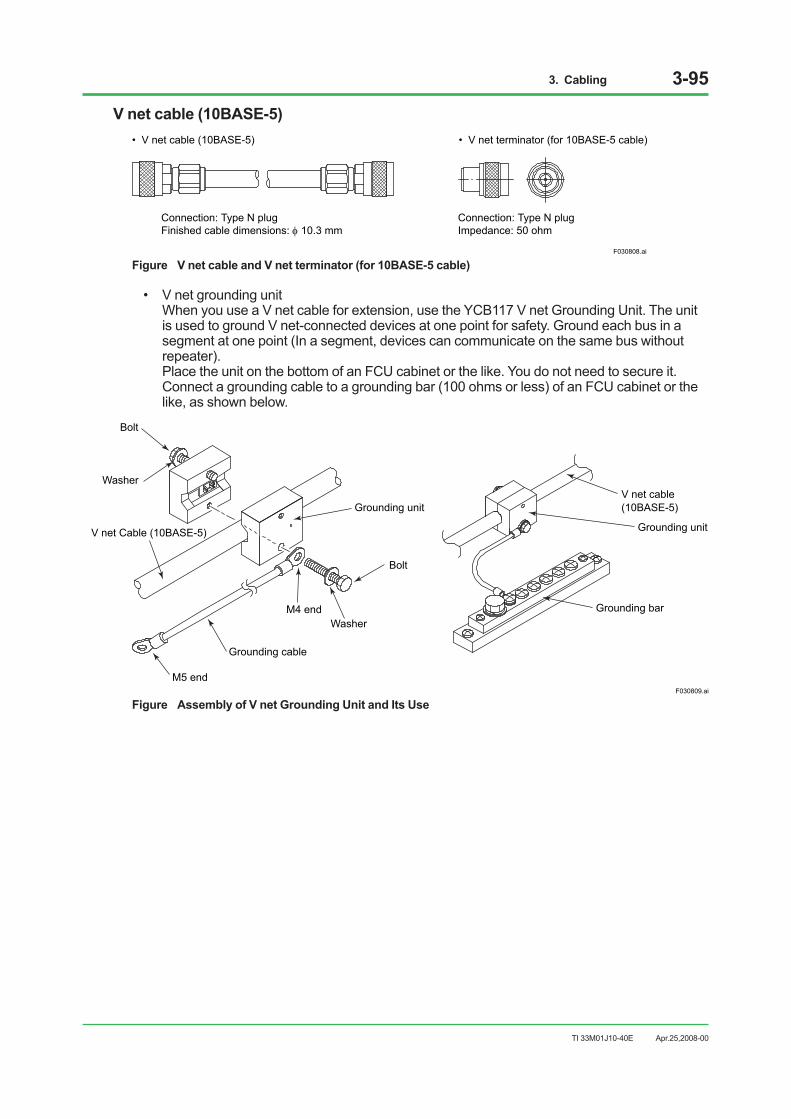
3. Cabling 3-95
TI 33M01J10-40E
V net cable (10BASE-5)• V net cable (10BASE-5)
Connection: Type N plugFinished cable dimensions: 10.3 mm
Connection: Type N plugImpedance: 50 ohm
F030808.ai
• V net terminator (for 10BASE-5 cable)
Figure V net cable and V net terminator (for 10BASE-5 cable)
• V net grounding unit When you use a V net cable for extension, use the YCB117 V net Grounding Unit. The unit is used to ground V net-connected devices at one point for safety. Ground each bus in a segment at one point (In a segment, devices can communicate on the same bus without repeater). Place the unit on the bottom of an FCU cabinet or the like. You do not need to secure it. Connect a grounding cable to a grounding bar (100 ohms or less) of an FCU cabinet or the like, as shown below.
F030809.ai
V net cable (10BASE-5)
Grounding unit
Grounding bar
Bolt
Washer
Bolt
WasherM4 end
M5 end
Grounding unit
V net Cable (10BASE-5)
Grounding cable
Figure Assembly of V net Grounding Unit and Its Use
Apr.25,2008-00

3. Cabling 3-96
TI 33M01J10-40E
• Clamp filter In order to enhance noise resistance, attach three clamp filters in succession at both ends of the V net cable (10BASE-5) near to the V net couplers. Refer to Figure for a typical mounting example.
F030810.ai
Clamp filter
Clamp filter
V net Cable (10BASE-5)
Figure Clamp filter
V net cable (10BASE-2)• V net cable (10BASE-2)
Connection: Type BNC plugFinished cable dimensions: 5 mm
Connection: Type BNC plugImpedance: 50 ohm
• V net terminator (for 10BASE-2 cable)
F030820.ai
Figure V net cable and V net terminator (for 10BASE-2 cable)
• T-type connector When the V net cable is connected, put the T-type connector between insulation sheets to prevent it from touching other metals. The surfaces of the insulation sheets that come with the T-type connector (2 sheets) are adhesive. The figure below shows how to attach them. Place two pieces of insulation sheets so that the adhesive surfaces face the T-type connector and sandwich the T-type connector between them. Press the two pieces of insulation sheets together tightly with your fingers, making sure that the sheets cover the metal part of the T-type connector.
F030819.ai
Insulation sheet
T-type connector
Figure Insulation Sheet
Apr.25,2008-00

3. Cabling 3-97
TI 33M01J10-40E
• BNC Connector Cover If V net (10BASE-2) cables are connected to the AFF50, install BNC connector covers to prevent the BNC connectors from coming into contact with other pieces of metal. Four BNC connector covers are supplied with the AFF50.
F030821.ai
Cover
V net cable
V net coupler unit
V net branchconnector
Figure BNC Connector Cover
Apr.25,2008-00

3. Cabling 3-98
TI 33M01J10-40E
ESB BusThe following is an example of connecting an ESB bus. Either ESB bus branching connector or the branching connector that has a built-in ESB bus terminator must be mounted to SB401 installed in ESB bus node unit. If a node unit is connected next, select ESB bus branching connector. If the node unit is the last one, select the branching connector that has a built-in ESB bus terminator.
F030811.ai
Bus1
ESB bus (duplexed)(connected to Bus1 if single)
REVISIONU H1 H2
MODELAIP532
STYLE1 SIYOKOGAWA
ESB BusCN1
RCV
SND-L
SND-R
Bus2
SB401+S9879UK
SB401+S9879UK
Bus2
to next node unit
Bus1
REVISIONU H1 H2
MODELAIP532
STYLE1 SIYOKOGAWA
ESB BusCN1
RCV
SND-L
SND-R
AFS30D
REVISIONU H1 H2
MODELAIP532
STYLE1 SIYOKOGAWA
ESB BusCN1
RCV
SND-L
SND-R
REVISIONU H1 H2
MODELAIP532
STYLE1 SIYOKOGAWA
ESB BusCN1
RCV
SND-L
SND-R
ANB10DConnector Unit
for ESB bus(S9879UK)
Connector Unit withTerminator for ESB bus
(S9880UK)
ESB bus cable (YCB301)
Screw tightening torque0.291±0.049 N•m
Figure ESB bus Connection (AFS30D)
Apr.25,2008-00

3. Cabling 3-99
TI 33M01J10-40E
Connector Unitfor ESB bus(S9879UK)
ANB10DConnector Unit with
terminator for ESB bus(S9880UK)
F030822.ai
SB401+S9879UK
SB401+S9879UK
Bus2
to next node unit
Bus1
ESB bus cable (YCB301)
Screw tightening torque0.291±0.049 N•m
Bus1 Bus2
ESB bus (duplexed)(connected to Bus1 if single)
AFF50D
ESB coupler(EC401)
CN2(CPU-L)
CN3(CPU-R)
CN1 ENBL
DSBL
CN1
CN2(CPU-L)
CN3(CPU-R)
ENBL
DSBL
TM1READY
FUSE RL1 CN1 (PSU-L)
CN2 (PSU-R)
TM2 100-120V AC , L N
Figure ESB bus Connection (AFF50D)
Apr.25,2008-00

3. Cabling 3-100
TI 33M01J10-40E
ER BusThe following is an example of connecting an ER bus. If no next station is connected, attach YCB148 Terminator. Avoid using ER bus cable with other cables and also avoid wiring its cable in parallel with others.
F030812.ai
EB401 ER bus cableYCB141
ESB bus node unitANB10D
ER bus node unitANR10D
to next ER bus node unit
Figure ER bus Connection (19-inch Rack Mountable Type)
Apr.25,2008-00

3. Cabling 3-101
TI 33M01J10-40E
How to wiring ER busThe figure shown below describes how to wiring ER bus:
F030813.ai
Connect to thenext ER bus node unit
Fix with using a cable fastenerat the front right edge of cable tray.
Separate from other cables as much as possible.
EB401
Terminator(YCB148)
Clamp filter(A1193MN)
Fix with using a cable fastenerat the front right edge of cable tray.
YCB141Separate from other cables.
Adjust the cable lengthon the cable tray if required.
EB501
ANB10D
ANR10D
Figure How to wiring ER bus
Apr.25,2008-00

3. Cabling 3-102
TI 33M01J10-40E
• Terminator
Regarding EB401 and EB501, if one side of T-type connector is terminal, mount a terminator. Two terminators are supplied with EB401.
• Clamp Filter
Regarding EB401 and EB501, mount clamp filters to both side of T-type connector. If one of the sides is terminal, mount a clamp filter to only the cable side. Two (four for dual-redundant) clamp filters are supplied with the remote node. For EB401, use the clamp filter supplied with the terminal remote node.
F030823.ai
Within 10 cmClamp Filter
Figure Clamp Filter
• T-type connector
When the ER bus cable is connected, put the T-type connector between insulation sheets to prevent it from touching other metals. The surfaces of the insulation sheets that come with the T-type connector (2 sheets) are adhesive. The figure below shows how to attach them. Place two pieces of insulation sheets so that the adhesive surfaces face the T-type connector and sandwich the T-type connector between them. Press the two pieces of insulation sheets together tightly with your fingers, making sure that the sheets cover the metal part of the T-type connector.
F030824.ai
Insulation sheet
T-type connector
Figure Insulation Sheet
Apr.25,2008-00
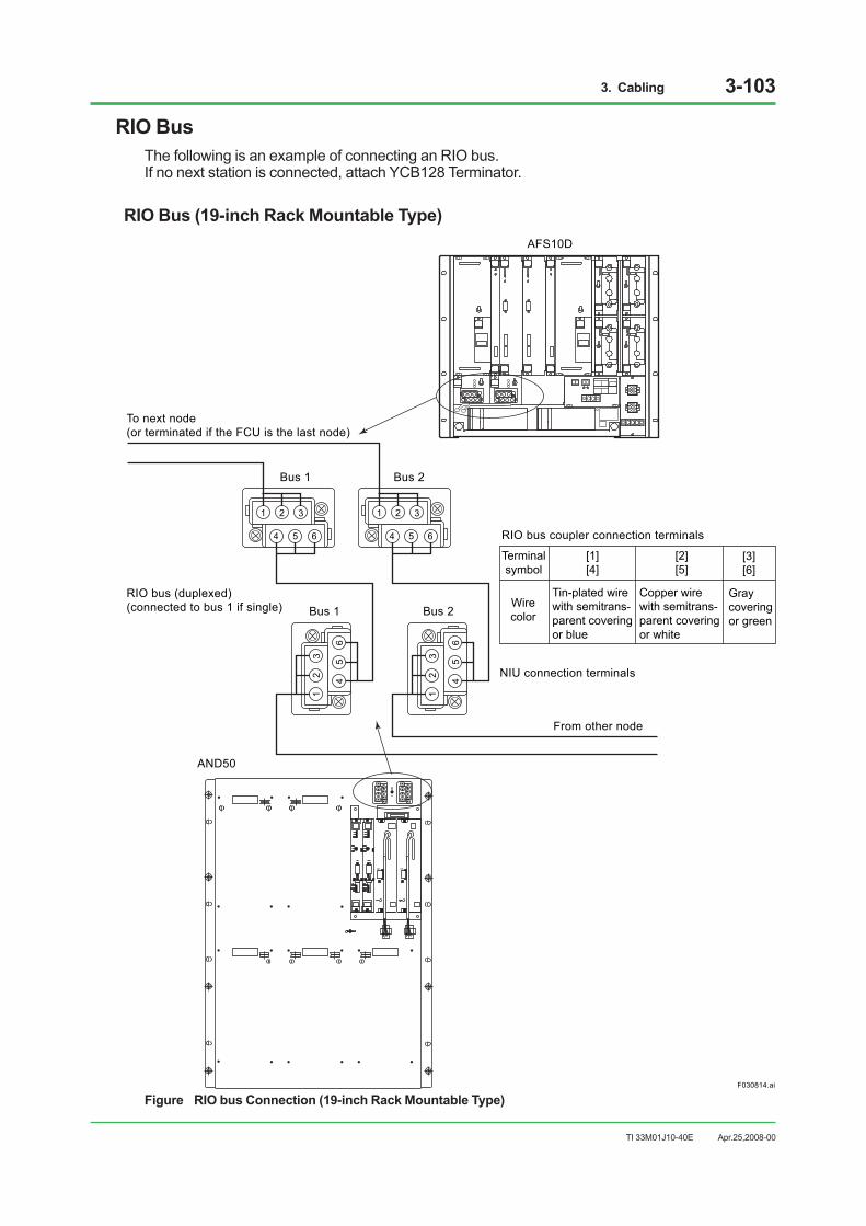
3. Cabling 3-103
TI 33M01J10-40E
RIO BusThe following is an example of connecting an RIO bus. If no next station is connected, attach YCB128 Terminator.
RIO Bus (19-inch Rack Mountable Type)
F030814.ai
To next node(or terminated if the FCU is the last node)
RIO bus (duplexed)(connected to bus 1 if single)
NIU connection terminals
From other node
RIO bus coupler connection terminals
AND50
AFS10D
1 2 3
4 5 6
12
3
45
6
12
3
45
6
1 2 3
4 5 6
Bus 1
Bus 1 Bus 2
Bus 2
Graycoveringor green
Tin-plated wirewith semitrans-parent covering or blue
Copper wirewith semitrans-parent coveringor white
[3][6]
Wirecolor
Terminalsymbol
[1][4]
[2][5]
OKOK
Figure RIO bus Connection (19-inch Rack Mountable Type)
Apr.25,2008-00

3. Cabling 3-104
TI 33M01J10-40E
RIO Bus (with Cabinet)Front of cabinet
From other node
Bus 1 Bus 2
Bus 1 Bus 2
NIU connectionterminals
RIO bus (dual-redundant)(connected to bus 1 if single)
Rear of cabinet
F030815.ai
1 2 3
4 5 6
1 2 3
4 5 6
1 2 3
4 5 6
1 2 3
4 5 6
RIO bus couplerconnection terminals
RIO bus unit
To next node(or terminated if the FCU is the last node)
Note: Connect the FCU to the next node from the rear RIO bus unit, or terminate it if it is the last node.
Figure RIO bus Connection (with Cabinet)
Apr.25,2008-00

3. Cabling 3-105
TI 33M01J10-40E
RIO Bus Arrangement
F030816.ai
Shield
[1] or [4] (Tin-plated semitransparent covering or blue)[2] or [5] (Copper wire with semitransparent covering or white)[3] or [6] (Gray covering or green)
Finished cable dimensions: 8.5 mmConnection: M4 Screw
Figure RIO bus Cable
• Grounding RIO Bus To avoid shock hazards, ground RIO bus cables at one point every segment. For grounding, see relevant IM.
F030817.ai
Terminal 1
Terminal 2
RIO busterminator
Coupler
Terminator connection terminals:Between [1] and [2]Connection: M4 Screw
There is no need to remove terminal screws,but simply loosen them; screws are designednot to fall out. (See figure).
Figure RIO Bus Terminator and Mounting Condition
F030818.ai
[3]
[4]
[5]
[1] initial state
[5] Solderless lug secured
Crosssectionalview
[2] Screw released
[3] Solderless lug inserted
[4] Solderless lug engaged
Tighten the screw.
Insert the top of the solderlesslug between the screw and the spring saddle and depress the saddle to produce a clearance.
Push in the solderless lugvertically to let the screw intothe screw hole in the lug.
Figure Connecting and terminating the RIO bus Cable
Apr.25,2008-00

3. Cabling 3-106
TI 33M01J10-40E
3.9 Connecting Optical Fiber CableThe optical bus repeater is used to convert part of the system’s communication bus to optical fiber cables. The optical fiber cables must be provided by user.
Connect the optical transceivers of a pair of optical bus repeaters as shown below:
F030901.ai
RDYRCVSND
OUT
IN
OPTICALLINK
RDYRCVSND
OUT
IN
OPTICALLINK
RDYRCVSND
OUT
IN
OPTICALLINK
RDYRCVSND
OUT
IN
OPTICALLINK
Opticalcord
Opticalfiber cable
Optical cord
Opticalcord
Opticalcord
Bus-1 Bus-2
Connected to correspondingoptical transceiver in redundant system
Bus-1optical transceiver
Bus-2optical transceiver
Bus-1 optical transceiver
Bus-2 optical transceiver
Optical cord and optical fiber cable connection (splicing box)
Optical connector
Must be suppliedby the user
Figure Example of Optical Cord and Optical Fiber Cable Connection (In redundant optical bus repeater (YNT51D) for Max.4 km)
Apr.25,2008-00

3. Cabling 3-107
TI 33M01J10-40E
To Use GI 62.5/125 Optical Fiber CableIt is recommended to use a GI 50/125 optical fiber cable (core diameter 50 µm, clad diameter 125 µm) for an optical bus repeater.To use a GI 62.5/125 optical fiber cable, follow the procedure below. Compared to a GI 50/125 optical fiber cable, a large volume of light is emitted by connecting a GI 62.5/125 optical fiber cable to the output connector of an optical bus repeater. If the input connector of an optical bus repeater receives a larger volume of light than the maximum volume of light to be received, data transmission fails. Therefore, connect a GI 62.5/125 optical fiber cable according to the procedure below.
1. To restrict a volume of light, you must insert a 10 m of GI 50/125 optical cord between the output connector of an optical bus repeater and a GI 62.5/125 optical fiber cable in the field.
2. To connect the two types of cables, use an optical adapter inside the splicing box located under the floor near a cabinet to install an optical bus repeater.
F030902.ai
RDYRCVSND
OUT
IN
OPTICALLINK
RDYRCVSND
OUT
IN
OPTICALLINK
Bus 1(Same as BUS 2)
Optical transceiver
Bus 1Optical transceiver
Optical connectors
GI 50/125 GI 62.5/125
GI 62.5/125 GI 50/125
GI 62.5/125 GI 62.5/125
: Splicing box
: Optical adaptor
: Fusion point
GI 62.5/125 Optical cord
GI 62.5/125 Optical fiber cable
GI 50/125 Optical cord (10 m)
Figure Connection of GI 62.5/125 Optical Fiber Cable
Apr.25,2008-00

3. Cabling 3-108
TI 33M01J10-40E
3.10 Alarm and Contact I/O Cabling
CAUTIONIt is recommended to use signal cables, relay terminals, relays, power units, and other devices that comply with CSA 61010 or CSA 950 (for 100-120 V AC) or EN 61010-1 (for 220-240 V AC) standards when connected to contact output terminal.
Status Contact Output ConnectionEach CENTUM VP device is provided with a terminal which makes contact output to external if a power failure or processor failure is detected. The output contact rating of each device is shown below.
Table Status Contact Output
Device Status Contact Output Contact Rating LPCKIT, YPCKIT Built-in PC failure 250 V AC/30 V DC, 2 A, 125 VA AFS10S/AFS10D, AFG10S/AFG10D (19-inch Rack Mountable Type) Power and processor failure 30 V DC, 0.3 A
AFS20S/AFS20D, AFG20S/AFG20D (with Cabinet) Power and processor failure 250 V AC/30 V DC, 2 A, 125 VA AFS30S/AFS30D, AFG30S/AFG30D (19-inch Rack Mountable Type) Power and processor failure 30 V DC, 0.3 A
AFS40S/AFS40D, AFG40S/AFG40D (with Cabinet) Power and processor failure 250 V AC/30 V DC, 2 A, 125 VA AFF50S/AFF50D (19-inch Rack Mountable Type) Power and processor failure 30 V DC, 0.3 A PFCS/PFCD Power and processor failure 30 V DC, 0.3 A ABC11S/ABC11D Power and processor failure 30 V DC, 0.3 A MHM/MHC Power 30 V DC, 0.3 A
Use of LampsWhen you want to turn on lamps using contacts, use the following lamps:
• The rated voltage of lamp does not exceed the rated contact voltage.
• When using incandescent lamps, their rush current does not exceed the rated contact current. It is considered to be 10 to 15 times the rated current. If the rush current exceed the rated contact current, use a dim lamp resister or a rush current preventing resistor. It is recommended to use a dim lamp resistor using 40 to 50 % of the lamp current rating, or a rush current preventing resistor using 80 to 90 % of the lamp current rating. A dim lamp resistor permits detection of lamp failure.
Be sure to test the lamp before installation.
F031001.ai
Rush current preventing resistorContact
Lamp
Contact
Lamp
Check brightness when lighted. Check brightness when lighted.
Figure Examples of Using Lamps
Apr.25,2008-00

3. Cabling 3-109
TI 33M01J10-40E
Use of RelaysContact protection and surge absorption can be provided in various manners. When using contacts output to drive relays and solenoids, the following precautions should be taken:
• Install a diode in parallel to induction load for noise prevention and contact protection.
• Use a relay circuit with voltage rating as low as possible for increased reliability.
• Select a diode having a reverse withstand voltage which is 10 times or larger than a circuit voltage and a forward current which exceeds a load current.
IMPORTANT Relays and solenoids cause reverse electromotive voltages at both coil ends due to inductive load. This phenomenon causes contact damage or noise, leading to device errors and adversely affecting the entire system.
When a DC Power Supply Is Used
F031002.ai
Contact
Powersupply
Inductive load such as electromagnetic valve
External circuitSystem side
Figure Example of Using Diode for Contact Protection
When a AC (or DC) Power Supply Is Used• Shunt the load with a resistor (R) and a capacitor (C).
• The recovery time increases when using relays or solenoid valves.
Inductiveload
F031003.ai
Note: Avoid direct AC voltage input to the contact output terminal on 19-inch rack mountable type.
Figure Example of Capacitor/Resistor-protected Circuit
Apr.25,2008-00

4. Installation Specifications 4-1
TI 33M01J10-40E
4. Installation SpecificationsThis section summarizes power consumption, in-rush current, breaker ratings, parts durability and other data for the installation of CENTUM VP system.
Electrical SpecificationsPower consumption (current) and other electrical data are shown below:
Table Electrical Specifications (1/3)
Equipment Input-voltage range Max. power
consumption (VA, A) (*1)
Heating value J/h
(*2)Voltage (V AC) Frequency (Hz)Reference value LPCKIT Enclosed Display Style Console Type HIS LCD Single Stacked (built in General Purpose PC) (*3)
100-120 50/60±3
520 VA 1370 × 103 (380 W)220-240 550 VA
Reference value LPCKIT Enclosed Display Style Console Type HIS LCD Dual Stacked (built in General Purpose PC) (*3)
100-120 50/60±3
590 VA 1620 × 103 (450 W)220-240 630 VA
Reference value YPCKIT Open Display Style Console Type HIS LCD Single Stacked (built in General Purpose PC) (*3)
100-120 50/60±3
560 VA 1370 × 103 (380 W)220-240 590 VA
Reference value YPCKIT Opened Display Style Console Type HIS LCD Dual Stacked (built in General Purpose PC) (*3)
100-120 50/60±3
670 VA 1550 × 103 (430 W)220-240 720 VA
AFS10S, AFG10S 19-inch Rack Mountable Type (excluding node) Field Control Unit
100-120 50/60±3
250 VA 432 × 103 (120 W)220-240 250 VA
24 V DC 4.5 A
AFS10D, AFG10D 19-inch Rack Mountable Type (excluding node) Duplexed Field Control Unit
100-120 50/60±3
400 VA 720 × 103 (200 W)220-240 410 VA
24 V DC 8 A
AFS20S, AFG20S With Cabinet (excluding node) Field Control Unit
100-120 50/60±3
300 VA 540 × 103 (150 W)220-240 330 VA
24 V DC 6 A
AFS20D, AFG20D With Cabinet (excluding node) Duplexed Field Control Unit
100-120 50/60±3
450 VA 828 × 103 (230 W)220-240 480 VA
24 V DC 10 A
AFS20S, AFG20S With Cabinet (including node) Field Control Unit
100-120 50/60±3
1700 VA 3960 × 103 (1100 W)220-240 2000 VA
24 V DC 50 A
AFS20D, AFG20D With Cabinet (including node) Duplexed Field Control Unit
100-120 50/60±3
1700 VA 3960 × 103 (1100 W)220-240 2000 VA
24 V DC 50 A
*1: Power consumption in steady operation is indicated in VA (AC) or A (DC). When power consumption varies according to the installed number of equipment, power consumption by the maximum number of units installed is listed.
*2: Heating value in steady operation is indicated in Joule/hour. When heating value varies according to the installed number of equipment, heating value by the maximum number of units installed is listed.
*3: The value obtained on the premise that the maximum power consumption of built-in PC is 400 VA. The service outlet is not included.
Apr.25,2008-00

4. Installation Specifications 4-2
TI 33M01J10-40E
Table Electrical Specifications (2/3)
Equipment Input-voltage range Max. power
consumption (VA, A) (*1)
Heating value J/h
(*2)Voltage (V AC) Frequency (Hz)
PFCS field control station (excl. I/O) 100-120
50/60±3 200 VA
680 × 103 (190 W)220-240 300 VA
24 V DC 9 A
PFCD field control station (excl. I/O) 100-120
50/60±3 200 VA
680 × 103 (190 W)220-240 300 VA
24 V DC 9 A
ANS20/ANS50 Node Interface Unit 100-120
50/60±3 320 VA
540 × 103 (150 W)220-240 320 VA
24 V DC 7.5 A
AND20/AND50 Dual-Redundant Node Interface Unit 100-120
50/60±3 320 VA
540 × 103 (150 W)220-240 320 VA
24 V DC 7.5 A
ACB21 I/O Expansion Cabinet (at maximum installation of RIO)
100-120 50/60±3
1600 VA 3240 × 103
(900 W) 220-240 1700 VA 24 V DC 42 A
AFS30S, AFG30S 19-inch Rack Mountable Type Field Control Unit for FIO
100-120 50/60±3
250 VA 432 × 103 (120 W) 220-240 250 VA
24 V DC 4.5 A
AFS30D, AFG30D 19-inch Rack Mountable Type Duplexed Field Control Unit for FIO
100-120 50/60±3
400 VA 720 × 103 (200 W) 220-240 410 VA
24 V DC 8 A
AFS40S, AFG40S with Cabinet (excluding node) Field Control Unit for FIO
100-120 50/60±3
300 VA 540 × 103 (150 W) 220-240 330 VA
24 V DC 6 A
AFS40D, AFG40D with Cabinet (excluding node) Duplexed Field Control Unit for FIO
100-120 50/60±3
450 VA 828 × 103 (230 W) 220-240 480 VA
24 V DC 10 A
AFS40S, AFG40S with Cabinet (including node) Field Control Unit for FIO
100-120 50/60±3
1800 VA 4680 × 103 (1300 W) 220-240 2100 VA
24 V DC 53 A
AFS40D, AFG40D with Cabinet (including node) Duplexed Field Control Unit for FIO
100-120 50/60±3
1800 VA 4680 × 103 (1300 W) 220-240 2100 VA
24 V DC 53 A
AFF50S 19-inch Rack Mountable Type Field Control Unit for FIO
100-120 50/60±3
200 VA 432 × 103 (120 W) 220-240 230 VA
24 V DC 5.5 A
AFF50D 19-inch Rack Mountable Type Duplexed Field Control Unit for FIO
100-120 50/60±3
200 VA 432 × 103 (120 W) 220-240 230 VA
24 V DC 5.5 A
ANB10S ESB Bus Node Unit (at maximum installation of FIO)
100-120 50/60±3
200 VA 432 × 103 (120 W) 220-240 230 VA
24 V DC 5.5 A
*1: Power consumption in steady operation is indicated in VA (AC) or A (DC). When power consumption varies according to the installed number of equipment, power consumption by the maximum number of units installed is listed.
*2: Heating value in steady operation is indicated in Joule/hour. When heating value varies according to the installed number of equipment, heating value by the maximum number of units installed is listed.
Apr.25,2008-00

4. Installation Specifications 4-3
TI 33M01J10-40E
Table Electrical Specifications (3/3)
Equipment Input-voltage range Max. power
consumption(VA, A) (*1)
Heating value J/h
(*2)Voltage (V AC) Frequency (Hz)
ANB10D Duplexed ESB Bus Node Unit (at maximum installation of FIO)
100-120 50/60±3
200 VA 432 x 103 (120 W) 220-240 230 VA
24 V DC 5.5 A
ANR10S ER Bus Node Unit (at maximum installation of FIO)
100-120 50/60±3
200 VA 432 x 103 (120 W) 220-240 230 VA
24 V DC 5.5 A
ANR10D Duplexed ER Bus Node Unit (at maximum installation of FIO)
100-120 50/60±3
200 VA 432 x 103 (120 W) 220-240 230 VA
24 V DC 5.5 A
ACB41 I/O Expansion Cabinet (at maximum installation of FIO)
100-120 50/60±3
1700 VA 4680 x 103 (1300 W) 220-240 1900 VA
24 V DC 46 A
YNT511/YNT522 single optical bus repeater (*4) 100-120
50/60±3 40 VA
80 x 103
(23 W) 220-240 55 VA 24 V DC 1 A
YNT512 single bus repeater (*4) 100-120
50/60±3 40 VA
80 x 103
(23 W) 220-240 55 VA 24 V DC 1 A
ACG10S Communication Gateway Unit 100-120
50/60±3 100 VA 270 x 103
(75 W)220-240 100 VA
ABC11S Bus Converter 100-120
50/60±3 180 VA
288 x 103 (80 W) 220-240 180 VA
24 V DC 4 A
ABC11D Dual-Redundant Bus Converter 100-120
50/60±3 320 VA
540 x 103 (150 W) 220-240 320 VA
24 V DC 7.5 A
*1: Power consumption in steady operation is indicated in VA (AC) or A (DC). When power consumption varies according to the installed number of equipment, power consumption by the maximum number of units installed is listed.
*2: Heating value in steady operation is indicated in Joule/hour. When heating value varies according to the installed number of equipment, heating value by the maximum number of units installed is listed.
*4: Power consumption and heating value double in the case of redundant system.
Maximum Power Consumption Depending on Installed Nodes (Model AND20)
Max. power consumption (VA) No. of installed nodes 0 1 2 3 4 5 6
AFS20D 450 770 1060 1260 1440 1580 1700 ACB21 (Expansion Cabinet) 80 400 720 1000 1250 1440 1600
Note: Node load is at max. installation
Apr.25,2008-00

4. Installation Specifications 4-4
TI 33M01J10-40E
Actual Power-On In-Rush Current of Each ComponentActual in-rush current data measured for each component is listed below:
Table System Equipment Power-On In-Rush Current
Model In-Rush current (A) In-Rush current (A) In-Rush current (A)
100 V AC 220 V AC 24 V DC Primary Secondary Primary Secondary Primary Secondary
AFS10S FCU (19-inch rack mountable type) 32 38 103 45 17 21
AFS10D Duplexed FCU (19-inch rack mountable type) 56 58 208 67 32 39
AFG10S FCU (19-inch rack mountable type) 32 38 103 45 17 21
AFG10D Duplexed FCU (19-inch rack mountable type) 56 58 208 67 32 39
AFS20S FCU (with cabinet) (with maximum no. of nodes installed) 133 118 418 267 67 59
AFS20D Duplexed FCU (with cabinet) (with maximum no. of nodes installed) 133 118 418 267 67 59
AFG20S FCU (with Cabinet) (with maximum no. of nodes installed) 133 118 418 267 67 59
AFG20D Duplexed FCU (with Cabinet) (with maximum no. of nodes installed) 133 118 418 267 67 59
AFS30S FCU (for FIO, 19-inch rack mountable type) 32 38 103 45 17 21
AFS30D Duplexed FCU (for FIO, 19-inch rack mountable type) 56 58 208 67 32 39
AFG30S FCU (for FIO, 19-inch rack mountable type) 32 38 103 45 17 21
AFG30D Duplexed FCU (for FIO, 19-inch rack mountable type) 56 58 208 67 32 39
AFS40S Field Control Unit (for FIO, with cabinet) (with maximum no. of 10 node units installed)
190 80 180 80 67 59
AFS40D Duplexed Field Control Unit (for FIO, with cabinet) (with maximum no. of 10 node units installed)
220 140 260 120 67 59
AFG40S FCU (with Cabinet) (with maximum no. of 10 node units installed) 190 80 180 80 67 59
AFG40D Duplexed FCU (with Cabinet) (with maximum no. of 10 node units installed) 220 140 260 120 67 59
AFF50S FCU (for FIO, rack mountable type) (with maximum no. of node units installed) 165 25 260 22 63 48
AFF50D Duplexed FCU (for FIO, rack mountable type) (with maximum no. of node units installed)
165 25 260 22 63 48
PFCS/PFCD Field Control Station (incl. 5 I/O units) 24 17 36 19 25 24
AND20/ AND50
Node interface unit (duplexed) (with 5 I/O units loaded) 31 66 173 88 18 12
ACB21 I/O expansion cabinet (with maximum no. of nodes installed) 117 117 440 256 64 63
YNT511D, YNT522D Optical bus repeater (dual-redundant) 48 5 112 12 40 4
YNT512D Bus repeater (dual-redundant) 48 5 112 12 40 4 ACG10S Communication gateway unit 25 4 50 8 – – ABC11D Bus converter (dual-redundant) 56 58 208 67 33 37
ACB41 I/O expansion cabinet (with maximum no. of node units installed) 117 117 440 256 64 63
ANR10D Node unit for dual-redundant ER bus 62 5 124 5 30 23
Apr.25,2008-00

4. Installation Specifications 4-5
TI 33M01J10-40E
Input current peak values and waveforms, influenced by input impedance, varies with system configurations, line sharing with other systems, and other factors. The rush current data shown above were measured under predetermined conditions (see below). Please note that the values are subject to change.The power input circuit, with an in-rush current limiting circuit, restrains primary in-rush current, turning any current exceeding the limit to secondary and successive rush current.
Measurement ConditionsInput voltage: 132/264 V AC, 50 Hz, and 24 V DCPower line impedance: Approx. 0.4 ohms (external line and internal impedance)Turn-on timing: At 50 Hz, 90° or 5 ms after the AC zero-crossing point(60 Hz data are almost identical to the 50 Hz data shown above.)
Note• The timing of the maximum primary/secondary in-rush current varies with devices.
• The restart in-rush current after a momentary power failure exceeds the above data and its timing is also different.
• For a system composed of multiple pieces of equipment, the in-rush current is normally smaller than the total of the in-rush currents by individual pieces of equipment.
Apr.25,2008-00

4. Installation Specifications 4-6
TI 33M01J10-40E
Maximum Power Consumption of FIOTable Maximum Power Consumption of FIO (1/2)
Model name Name
Max. current consumption 5 V DC (mA)
Max. current consumption 24 V DC (mA)
Bus Interface Module EB401 ER Bus Interface Master Module 700 – Analog I/O Modules AAI141 Analog Input Module (4 to 20 mA, 16-channel, Non-Isolated) 310 450 AAV141 Analog Input Module (1 to 5 V, 16-channel, Non-Isolated) 350 – AAV142 Analog Input Module (-10 to +10 V, 16-channel, Non-Isolated) 350 –
AAI841 Analog I/O Module (4 to 20 mA, 8-channel Input/8-channel Output, Non-Isolated) 310 500
AAB841 Analog I/O Module (1 to 5 V Input, 4 to 20 mA Output, 8-channel Input/ 8-channel Output, Non-Isolated) 310 250
AAV542 Analog Output Module (-10 to +10 V, 16-channel, Non-Isolated) 450 – AAI143 Analog Input Module (4 to 20 mA, 16-channel, Isolated) 230 540 AAI543 Analog Output Module (4 to 20 mA, 16-channel, Isolated) 230 540 AAV144 Analog Input Module (-10 to +10 V, 16-channel, Isolated) 500 – AAV544 Analog Output Module (-10 to +10 V, 16-channel, Isolated) 860 –
AAT141 TC/mV Input Module (TC: R, J, K, E, T, B, S, N/mV: -100 to 150 mV, 16-channel, Isolated) 450 –
AAR181 RTD Input Module (RTD: Pt100 ohm, 12-channel, Isolated) 450 – AAI135 Analog Input Module (4 to 20 mA, 8-channel, Isolated Channels) 360 450
AAI835 Analog I/O Module (4 to 20 mA, 4-channel Input/4-channel Output, Isolated Channels) 360 450
AAT145 TC/mV Input Module (TC: R, J, K, E, T, B, S, N/mV: -100 to 150 mV, 16-channel, Isolated Channels) 350 –
AAR145 RTD/POT Input Module (RTD: Pt100 ohm/POT: 0 to 10 kohm, 16-channel, Isolated Channels) 350 –
AAP135 Pulse Input Module (8-channel, Pulse Count, 0 to 10 kHz, Isolated Channels) 300 400
AAP149 Pulse Input Module for Compatible PM1 (16-channel, Pulse Count, 0 to 6 kHz, Non-Isolated) 400 –
AAP849 Pulse Input/Analog Output Module for compatible PAC (Pulse count Input, 4 to 20mA Output, 8-channel Input/8-channel Output, Non-Isolated)
310 250
Apr.25,2008-00
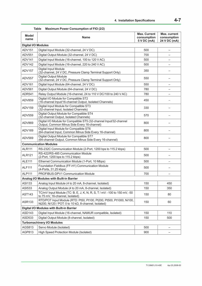
4. Installation Specifications 4-7
TI 33M01J10-40E
Table Maximum Power Consumption of FIO (2/2)
Model name Name
Max. Current consumption 5 V DC (mA)
Max. current consumption 24 V DC (mA)
Digital I/O Modules ADV151 Digital Input Module (32-channel, 24 V DC) 500 – ADV551 Digital Output Module (32-channel, 24 V DC) 700 – ADV141 Digital Input Module (16-channel, 100 to 120 V AC) 500 – ADV142 Digital Input Module (16-channel, 220 to 240 V AC) 500 –
ADV157 Digital Input Module (32-channel, 24 V DC, Pressure Clamp Terminal Support Only) 350 –
ADV557 Digital Output Module (32-channel, 24 V DC, Pressure Clamp Terminal Support Only) 550 –
ADV161 Digital Input Module (64-channel, 24 V DC) 550 – ADV561 Digital Output Module (64-channel, 24 V DC) 780 – ADR541 Relay Output Module (16-channel, 24 to 110 V DC/100 to 240 V AC) 780 –
ADV859 Digital I/O Module for Compatible ST2 (16-channel Input/16-channel Output, Isolated Channels) 450 –
ADV159 Digital Input Module for Compatible ST3 (32-channel Input, Isolated Channels) 330 –
ADV559 Digital Output Module for Compatible ST4 (32-channel Output, Isolated Channels) 570 –
ADV869 Digital I/O Module for Compatible ST5 (32-channel Input/32-channel Output, Common Minus Side Every 16-channel) 800 –
ADV169 Digital Input Module for Compatible ST6 (64-channel Input, Common Minus Side Every 16-channel) 800 –
ADV569 Digital Output Module for Compatible ST7 (64-channel Output, Common Minus Side Every 16-channel) 800 –
Communication Modules ALR111 RS-232C Communication Module (2-Port, 1200 bps to 115.2 kbps) 500 –
ALR121 RS-422/RS-485 Communication Module (2-Port, 1200 bps to 115.2 kbps) 500 –
ALE111 Ethernet Communication Module (1-Port, 10 Mbps) 500 –
ALF111 Foundation Fieldbus (FF-H1) Communication Module (4-Ports, 31.25 kbps) 500 –
ALP111 PROFIBUS-DPV1 Communication Module 700 – Analog I/O Modules with Built-in Barrier ASI133 Analog Input Module (4 to 20 mA, 8-channel, Isolated) 150 450 ASI533 Analog Output Module (4 to 20 mA, 8-channel, Isolated) 150 350
AST143 TC/mV Input Module (TC: B, E, J, K, N, R, S, T / mV: -100 to 150 mV, -50 to 75 mV, 16-channel, Isolated) 150 80
ASR133 RTD/POT Input Module (RTD: Pt50, Pt100, Pt200, Pt500, Pt1000, Ni100, Ni200, Ni120 / POT: 0 to 10 kΩ, 8-channel, Isolated) 150 60
Digital I/O Modules with Built-in Barrier ASD143 Digital Input Module (16-channel, NAMUR compatible, Isolated) 150 110 ASD533 Digital Output Module (8-channel, Isolated) 150 500 Turbomachinery I/O Modules AGS813 Servo Module (Isolated) 500 – AGP813 High Speed Protection Module (Isolated) 900 –
Apr.25,2008-00
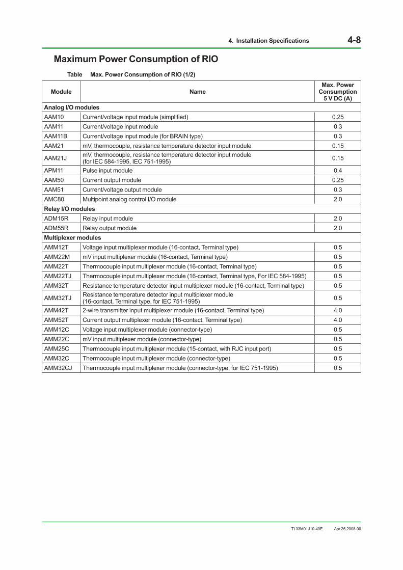
4. Installation Specifications 4-8
TI 33M01J10-40E
Maximum Power Consumption of RIOTable Max. Power Consumption of RIO (1/2)
Module Name Max. Power
Consumption 5 V DC (A)
Analog I/O modules AAM10 Current/voltage input module (simplified) 0.25 AAM11 Current/voltage input module 0.3 AAM11B Current/voltage input module (for BRAIN type) 0.3 AAM21 mV, thermocouple, resistance temperature detector input module 0.15
AAM21J mV, thermocouple, resistance temperature detector input module (for IEC 584-1995, IEC 751-1995) 0.15
APM11 Pulse input module 0.4 AAM50 Current output module 0.25 AAM51 Current/voltage output module 0.3 AMC80 Multipoint analog control I/O module 2.0 Relay I/O modules ADM15R Relay input module 2.0 ADM55R Relay output module 2.0 Multiplexer modules AMM12T Voltage input multiplexer module (16-contact, Terminal type) 0.5 AMM22M mV input multiplexer module (16-contact, Terminal type) 0.5 AMM22T Thermocouple input multiplexer module (16-contact, Terminal type) 0.5 AMM22TJ Thermocouple input multiplexer module (16-contact, Terminal type, For IEC 584-1995) 0.5 AMM32T Resistance temperature detector input multiplexer module (16-contact, Terminal type) 0.5
AMM32TJ Resistance temperature detector input multiplexer module (16-contact, Terminal type, for IEC 751-1995) 0.5
AMM42T 2-wire transmitter input multiplexer module (16-contact, Terminal type) 4.0 AMM52T Current output multiplexer module (16-contact, Terminal type) 4.0 AMM12C Voltage input multiplexer module (connector-type) 0.5 AMM22C mV input multiplexer module (connector-type) 0.5 AMM25C Thermocouple input multiplexer module (15-contact, with RJC input port) 0.5 AMM32C Thermocouple input multiplexer module (connector-type) 0.5 AMM32CJ Thermocouple input multiplexer module (connector-type, for IEC 751-1995) 0.5
Apr.25,2008-00

4. Installation Specifications 4-9
TI 33M01J10-40E Apr.25,2008-00
Table Max. Power Consumption of RIO (2/2)
Module Name Max. Power
Consumption 5 V DC (A)
Digital I/O modules ADM11T Contact input module (16-contact, Terminal type) 0.6 ADM12T Contact input module (32-contact, Terminal type) 0.6 ADM51T Contact output module (16-contact, Terminal type) 0.6 ADM52T Contact output module (32-contact, Terminal type) 0.6 ADM11C Contact input module (16-point, Connector type) 0.6 ADM12C Contact input module (32-point, Connector type) 0.6 ADM51C Contact output module (16-point, Connector type) 0.6 ADM52C Contact output module (32-point, Connector type) 0.6 Communication modules ACM11 RS-232C Communication module 1.0 ACM12 RS-422/RS-485 Communication module 1.0 ACM21 RS-232C Communication card 1.0 ACM22 RS-422/RS-485 Communication card 1.0 ACM71 Ethernet Communication module (for PFC) 1.2 ACF11 Fieldbus Communication module 1.4 ACP71 PROFIBUS Communication module 0.6

4. Installation Specifications 4-10
TI 33M01J10-40E Apr.25,2008-00
Breaker SpecificationsBreaker ratings are listed below:
Table Breaker Ratings (1/2)
Equipment Built-in breaker rating (A/V)
External breaker rating (Recommend) (A/V) (*1)
LPCKIT, YPCKIT console assembly (100 V AC) 15/250 30/250 LPCKIT, YPCKIT console assembly (220 V AC) 15/250 30/250 PFCS field control station (100 V AC system) 6.3/250 (fuse) 15/250 PFCS field control station (220 V AC system) 6.3/250 (fuse) 15/250 PFCS field control station (24 V DC) 15/250 (fuse) 30/24 PFCD dual-redundant field control station (100 V AC system) 6.3/250 (fuse) 15/250 PFCD dual-redundant field control station (220 V AC system) 6.3/250 (fuse) 15/250 PFCD dual-redundant field control station (24 V DC) 15/250 (fuse) 30/24 YNT511/YNT522 optical bus repeater (100 V AC system) 1/250 (fuse) 5/250 YNT511/YNT522 optical bus repeater (220 V AC system) 2/250 (fuse) 10/250 YNT511/YNT522 optical bus repeater (24 V DC) 2/250 (fuse) 10/250 YNT512 bus repeater (100 V AC system) 1/250 (fuse) 5/250 YNT512 bus repeater (220 V AC system) 2/250 (fuse) 10/250 YNT512 bus repeater (24 V DC) 2/250 (fuse) 10/250 AFS10S/AFS10D, AFG10S/AFG10D field control unit (100 V AC) 8/250 (fuse) 15/250 AFS10S/AFS10D, AFG10S/AFG10D field control unit (220 V AC) 6.3/250 (fuse) 15/250 AFS10S/AFS10D, AFG10S/AFG10D field control unit (24 V DC) 15/250 (fuse) 30/24 ANS50/AND50 Node interface unit (100 V AC) 8/250 (fuse) 15/250 ANS50/AND50 Node interface unit (220 V AC) 6.3/250 (fuse) 15/250 ANS50/AND50 Node interface unit (24 V DC) 15/250 (fuse) 30/24 AFS20S/AFS20D, AFG20S/AFG20D field control unit (100 V, 220 V AC) 15/250 (two) (*2) 40/250
AFS20S/AFS20D, AFG20S/AFG20D field control unit (24 V DC) 30/24 (two) 100/24 ACB21 I/O expansion cabinet (100 V, 220 V AC) 15/250 (two) (*2) 40/250 ACB21 I/O expansion cabinet (24 V DC) 30/24 (two) 100/24
*1: Recommended.*2: Breaker consists of two 15AT NFBs (no-fuse breakers), as shown in the following figure. Up to 30 A can be fed. However, when
15 A or more passes through one breaker, both NFBs shut down.

4. Installation Specifications 4-11
TI 33M01J10-40E Apr.25,2008-00
Table Breaker Ratings (2/2)
Equipment Built-in breaker rating (A/V)
External breaker rating (Recommend) (A/V) (*1)
AFS30S/AFS30D, AFG30S/AFG30D field control unit (100 V AC) 8/250 (fuse) 15/250 AFS30S/AFS30D, AFG30S/AFG30D field control unit (220 V AC) 8/250 (fuse) 15/250 AFS30S/AFS30D, AFG30S/AFG30D field control unit (24 V DC) 15/25 (fuse) 30/24 AFS40S/AFS40D, AFG40S/AFG40D field control unit (100 V AC, 220 V AC) 20/250 (two) (*3) 50/250
AFS40S/AFS40D, AFG40S/AFG40D field control unit (24 V DC) 30/24 (two) 100/24 AFF50S/AFF50D field control unit (100 V AC, 220 V AC) 6.3/250 (fuse) 15/250 AFF50S/AFF50D field control unit (24 V DC) 10/250 (fuse) 20/250 ANB10S/10D ESB bus node unit (100 V,220 V AC) ANR10S/10D ER bus node unit (100 V,220 V AC) 6.3/250 (fuse) 15/250
ANB10S/10D ESB bus node unit (24 V DC) ANR10S/10D ER bus node unit (24 V DC) 10/250 (fuse) 20/250
ACB41 I/O expansion cabinet (100 V, 220 V AC) 20/250 (two) (*3) 40/250 ACB41 I/O expansion cabinet (24 V DC) 30/24 (two) 100/24 ABC11S/ABC11D Bus converter (100 V AC) 8/250 (fuse) 15/250 ABC11S/ABC11D Bus converter (220 V AC) 6.3/250 (fuse) 15/250 ABC11S/ABC11D Bus converter (24 V DC) 15/250 (fuse) 30/24 ACG10S Communication gateway unit (100 V AC) 3/250 (fuse) 5/250 ACG10S Communication gateway unit (220 V AC) 3.15/250 (fuse) 5/250
*1: Recommended.*3: Breaker consists of two 20AT NFBs (no-fuse breakers), as shown in the following figure. Up to 40 A can be fed. However, when
20 A or more passes through one breaker, both NFBs shut down.
F040107.ai
FCU+
Front Rear
Attachment bar15AT/20AT 15AT/20AT
L N
Figure Breaker
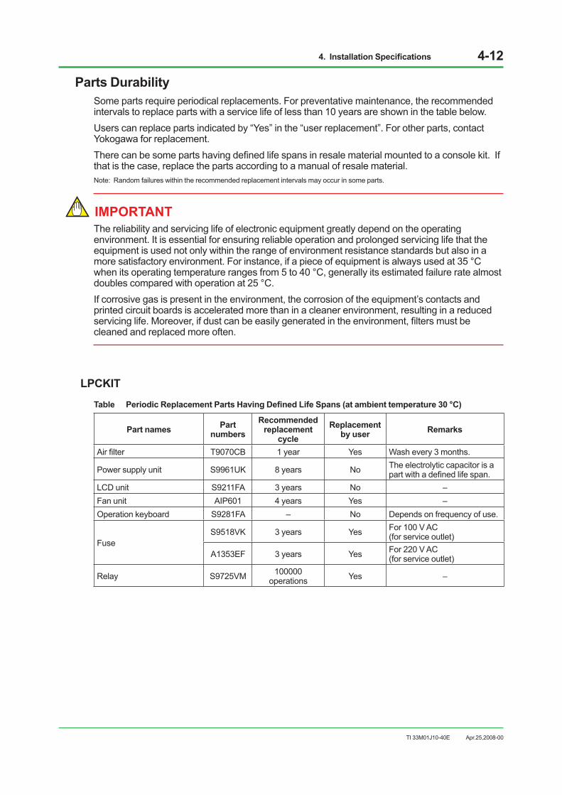
4. Installation Specifications 4-12
TI 33M01J10-40E Apr.25,2008-00
Parts DurabilitySome parts require periodical replacements. For preventative maintenance, the recommended intervals to replace parts with a service life of less than 10 years are shown in the table below.Users can replace parts indicated by “Yes” in the “user replacement”. For other parts, contact Yokogawa for replacement.There can be some parts having defined life spans in resale material mounted to a console kit. If that is the case, replace the parts according to a manual of resale material.Note: Random failures within the recommended replacement intervals may occur in some parts.
IMPORTANT The reliability and servicing life of electronic equipment greatly depend on the operating environment. It is essential for ensuring reliable operation and prolonged servicing life that the equipment is used not only within the range of environment resistance standards but also in a more satisfactory environment. For instance, if a piece of equipment is always used at 35 °C when its operating temperature ranges from 5 to 40 °C, generally its estimated failure rate almost doubles compared with operation at 25 °C.If corrosive gas is present in the environment, the corrosion of the equipment’s contacts and printed circuit boards is accelerated more than in a cleaner environment, resulting in a reduced servicing life. Moreover, if dust can be easily generated in the environment, filters must be cleaned and replaced more often.
LPCKIT
Table Periodic Replacement Parts Having Defined Life Spans (at ambient temperature 30 °C)
Part names Part numbers
Recommended replacement
cycle Replacement
by user Remarks
Air filter T9070CB 1 year Yes Wash every 3 months.
Power supply unit S9961UK 8 years No The electrolytic capacitor is a part with a defined life span.
LCD unit S9211FA 3 years No – Fan unit AIP601 4 years Yes – Operation keyboard S9281FA – No Depends on frequency of use.
Fuse S9518VK 3 years Yes For 100 V AC
(for service outlet)
A1353EF 3 years Yes For 220 V AC (for service outlet)
Relay S9725VM 100000 operations Yes –
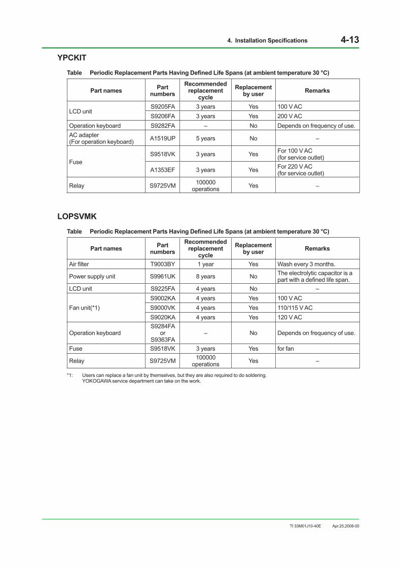
4. Installation Specifications 4-13
TI 33M01J10-40E
YPCKIT
Table Periodic Replacement Parts Having Defined Life Spans (at ambient temperature 30 °C)
Part names Part numbers
Recommended replacement
cycle Replacement
by user Remarks
LCD unit S9205FA 3 years Yes 100 V AC S9206FA 3 years Yes 200 V AC
Operation keyboard S9282FA – No Depends on frequency of use. AC adapter (For operation keyboard) A1519UP 5 years No –
Fuse S9518VK 3 years Yes For 100 V AC
(for service outlet)
A1353EF 3 years Yes For 220 V AC (for service outlet)
Relay S9725VM 100000 operations Yes –
LOPSVMK
Table Periodic Replacement Parts Having Defined Life Spans (at ambient temperature 30 °C)
Part names Part numbers
Recommended replacement
cycleReplacement
by user Remarks
Air filter T9003BY 1 year Yes Wash every 3 months.
Power supply unit S9961UK 8 years No The electrolytic capacitor is a part with a defined life span.
LCD unit S9225FA 4 years No –
Fan unit(*1)S9002KA 4 years Yes 100 V ACS9000VK 4 years Yes 110/115 V ACS9020KA 4 years Yes 120 V AC
Operation keyboardS9284FA
or S9363FA
– No Depends on frequency of use.
Fuse S9518VK 3 years Yes for fan
Relay S9725VM 100000 operations Yes –
*1: Users can replace a fan unit by themselves, but they are also required to do soldering. YOKOGAWA service department can take on the work.
Apr.25,2008-00

4. Installation Specifications 4-14
TI 33M01J10-40E Apr.25,2008-00
LOPXLMK
Table Periodic Replacement Parts Having Defined Life Spans (at ambient temperature 30 °C)
Part names Part numbers
Recommended replacement
cycleReplacement
by user Remarks
Air filter T9050NY 1 year Yes Wash every 3 months.
Power supply unit S9961UK 8 years No The electrolytic capacitor is a part with a defined life span.
LCD unit S9388FA 3 years No – LCD unit S9389FA 3 years No – Fan unit AIP601 4 years Yes – Operation keyboard S9390FA – No Depends on frequency of use.
FuseS9518VK 3 years Yes For 100 V AC
(for service outlet)
A1353EF 3 years Yes For 220 V AC(for service outlet)
Relay S9725VM 100000operations Yes –
AIP827
Table Periodic Replacement Parts Having Defined Life Spans (at ambient temperature 30 °C)
Part names Part numbers
Recommended replacement
cycleReplacement
by user Remarks
AC adapter A1519UP 5 years Yes – AIP827 – – No Depends on frequency of use.
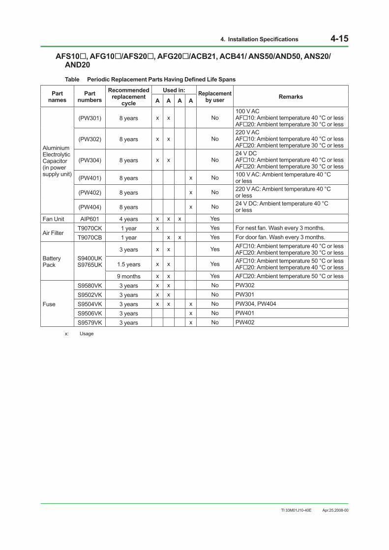
4. Installation Specifications 4-15
TI 33M01J10-40E Apr.25,2008-00
AFS10, AFG10/AFS20, AFG20/ACB21, ACB41/ ANS50/AND50, ANS20/AND20
Table Periodic Replacement Parts Having Defined Life Spans
Part names
Part numbers
Recommended replacement
cycle
Used in: Replacement by user Remarks A A A A
Aluminium Electrolytic Capacitor (in power supply unit)
(PW301) 8 years x x No100 V AC AF10: Ambient temperature 40 °C or less AF20: Ambient temperature 30 °C or less
(PW302) 8 years x x No220 V AC AF10: Ambient temperature 40 °C or less AF20: Ambient temperature 30 °C or less
(PW304) 8 years x x No24 V DC AF10: Ambient temperature 40 °C or less AF20: Ambient temperature 30 °C or less
(PW401) 8 years x No 100 V AC: Ambient temperature 40 °C or less
(PW402) 8 years x No 220 V AC: Ambient temperature 40 °C or less
(PW404) 8 years x No 24 V DC: Ambient temperature 40 °C or less
Fan Unit AIP601 4 years x x x Yes
Air Filter T9070CK 1 year x Yes For nest fan. Wash every 3 months.T9070CB 1 year x x Yes For door fan. Wash every 3 months.
Battery Pack
S9400UK S9765UK
3 years x x Yes AF10: Ambient temperature 40 °C or less AF20: Ambient temperature 30 °C or less
1.5 years x x Yes AF10: Ambient temperature 50 °C or less AF20: Ambient temperature 40 °C or less
9 months x x Yes AF20: Ambient temperature 50 °C or less
Fuse
S9580VK 3 years x x No PW302S9502VK 3 years x x No PW301S9504VK 3 years x x x No PW304, PW404S9506VK 3 years x No PW401S9579VK 3 years x No PW402
x: Usage

4. Installation Specifications 4-16
TI 33M01J10-40E Apr.25,2008-00
AFS30, AFG30/AFS40, AFG40/ANB10/ANR10
Table Periodic Replacement Parts Having Defined Life Spans
Part names
Part numbers
Recommended replacement
cycle
Used in: Remarks A A A A
Aluminium Electrolytic Capacitor (in power supply unit)
(PW301) 8 years x x No100 V AC AF30: Ambient temperature 40 °C or less AF40: Ambient temperature 30 °C or less
(PW302) 8 years x x No220 V AC AF30: Ambient temperature 40 °C or less AF40: Ambient temperature 30 °C or less
(PW304) 8 years x x No24 V DC AF30: Ambient temperature 40 °C or less AF40: Ambient temperature 30 °C or less
(PW481) 8 years x x No 100 V AC: Ambient temperature 40 °C or less
(PW482) 8 years x x No 220 V AC: Ambient temperature 40 °C or less
(PW484) 8 years x x No 24 V DC: Ambient temperature 40 °C or less
Fan Unit AIP601 4 years x x Yes
Air Filter T9070CK 1 year x Yes For nest fan. Wash every 3 months. T9070CB 1 year x Yes For door fan. Wash every 3 months.
Battery Pack
S9400UK S9765UK
3 years x x Yes AF30: Ambient temperature 40 °C or less AF40: Ambient temperature 30 °C or less
1.5 years x x Yes AF30: Ambient temperature 50 °C or less AF40: Ambient temperature 40 °C or less
9 months x x Yes AF40: Ambient temperature 50 °C or less
Fuse
S9580VK 3 years x x No PW302 S9502VK 3 years x x No PW301 S9504VK 3 years x x No PW304, PW404S9109VK 8 years x x No PW481, PW482 A1546EF 8 years x x No PW484
x: Usage
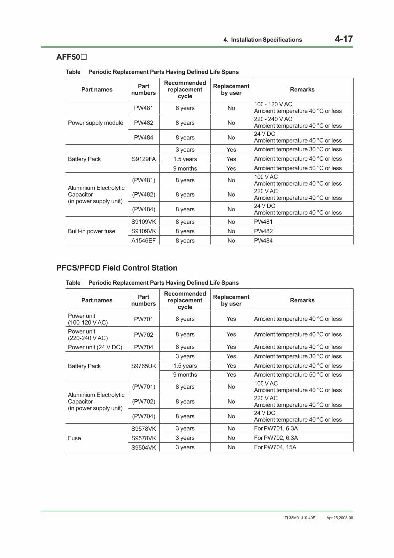
4. Installation Specifications 4-17
TI 33M01J10-40E Apr.25,2008-00
AFF50
Table Periodic Replacement Parts Having Defined Life Spans
Part names Part numbers
Recommended replacement
cycle Replacement
by user Remarks
Power supply module
PW481 8 years No 100 - 120 V AC Ambient temperature 40 °C or less
PW482 8 years No 220 - 240 V ACAmbient temperature 40 °C or less
PW484 8 years No 24 V DCAmbient temperature 40 °C or less
Battery Pack S9129FA 3 years Yes Ambient temperature 30 °C or less
1.5 years Yes Ambient temperature 40 °C or less9 months Yes Ambient temperature 50 °C or less
Aluminium Electrolytic Capacitor (in power supply unit)
(PW481) 8 years No 100 V ACAmbient temperature 40 °C or less
(PW482) 8 years No 220 V ACAmbient temperature 40 °C or less
(PW484) 8 years No 24 V DCAmbient temperature 40 °C or less
Built-in power fuse S9109VK 8 years No PW481 S9109VK 8 years No PW482 A1546EF 8 years No PW484
PFCS/PFCD Field Control Station
Table Periodic Replacement Parts Having Defined Life Spans
Part names Part numbers
Recommended replacement
cycle Replacement
by user Remarks
Power unit (100-120 V AC) PW701 8 years Yes Ambient temperature 40 °C or less
Power unit (220-240 V AC) PW702 8 years Yes Ambient temperature 40 °C or less
Power unit (24 V DC) PW704 8 years Yes Ambient temperature 40 °C or less
Battery Pack S9765UK 3 years Yes Ambient temperature 30 °C or less
1.5 years Yes Ambient temperature 40 °C or less9 months Yes Ambient temperature 50 °C or less
Aluminium Electrolytic Capacitor (in power supply unit)
(PW701) 8 years No 100 V ACAmbient temperature 40 °C or less
(PW702) 8 years No 220 V ACAmbient temperature 40 °C or less
(PW704) 8 years No 24 V DCAmbient temperature 40 °C or less
Fuse S9578VK 3 years No For PW701, 6.3AS9578VK 3 years No For PW702, 6.3AS9504VK 3 years No For PW704, 15A

4. Installation Specifications 4-18
TI 33M01J10-40E Apr.25,2008-00
YNT511/YNT522 Optical Bus Repeater and YNT512 Bus Repeater
Table Periodic Replacement Parts Having Defined Life Spans
Part names Part numbers
Recommended replacement
cycle Replacement
by user Remarks
Power unit (100-120 V AC) PW501 8 years Yes Ambient temperature 40 °C or less
Power unit (220-240 V AC) PW502 8 years Yes Ambient temperature 40 °C or less
Power unit (24 V DC) PW504 8 years Yes Ambient temperature 40 °C or less
Fuse A1361EF 3 years Yes For PW501, 1 A A1349EF 3 years Yes For PW502, 2 A A1363EF 3 years Yes For PW504, 2 A
ACG10S
Table Periodic Replacement Parts Having Defined Life Spans
Part names Part numbers
Recommended replacement
cycle Replacement
by user Remarks
Power unit A1057UP 8 years No 100/220 V AC power supply Ambient temperature 40 °C on less
Fan unit S9402UK 4 years YesBattery Pack S9400UK 3 years Yes Ambient temperature 30 °C or less Air filter T9051MK 1 year Yes Clean it every three months Lithium battery – 10 years No For real time clock
Fuse S9517VK 3 years Yes 100 V AC power supply (3A) A1351EF 3 years Yes 220 V AC power supply (3.15 A)

4. Installation Specifications 4-19
TI 33M01J10-40E Apr.25,2008-00
ABC10S, ABC11D
Table Periodic Replacement Parts Having Defined Life Spans
Part names Part numbers Recommended Replacement Interval
Replacement by user Remarks
Air Filter T9070CK 1 year Yes Clean it every three monthsFun AIP601 4 years Yes
Battery Pack S9400UK 3 years Yes Ambient temperature 30 °C or less
1.5 years Yes Ambient temperature 40 °C or less9 months Yes Ambient temperature 50 °C or less
Aluminium Electrolytic Capacitor (in power supply unit)
(PW301) 8 years No 100 V ACAmbient temperature 40 °C or less
(PW302) 8 years No 220 V ACAmbient temperature 40 °C or less
(PW304) 8 years No 24 V DCAmbient temperature 40 °C or less
Built-in power fuse S9052VK 3 years No 100-120 V AC, 250 V, 8 A, FS9580VK 3 years No 220-240 V AC, 250 V, 6.3 A, FS9504VK 3 years No 24 V DC, 250 V, 15 A, F
Paint ColorsTable Paint Colors
Painted section Paint color (Reference Munsell values in parentheses) Major unit types
Basic color Frosty white (2.5Y8.4/1.2) LPCKIT, YPCKIT, YAX801, AFS20S/AFS20D, AFS40S/AFS40D, AFG20S/AFG20D, AFG40S/AFG40D
Channel base Spring Black (3.3PB2.5/0.5) LPH21C, YPCKIT, YAX801, AFS20S/AFS20D, AFS40S/AFS40D, AFG20S/AFG20D, AFG40S/AFG40D

4. Installation Specifications 4-20
TI 33M01J10-40E
Notes for Installing DevicesThis section describes notes for installing devices and installation restrictions.
Rules of Connection for the Housekeeping Unit (HKU)The HKU owns a function which controls temperature rises by rotating the fans at high speed if the intake temperature becomes 35 °C or more, or the exhaust temperature becomes 40 °C or more in the I/O expansion cabinet (ACB21). When installing cabinet installation type nodes (when suffix codes -S1 or -S2 are selected) into the I/O expansion cabinet (ACB21), a connection between the HKU and the node is needed. When connecting, even with generation, a specification of which node is to be connected to the HKU must be made. When installing cabinet installation type nodes into the I/O expansion cabinet (ACB21), the connection between the HKU and node will be prioritized by R3→R2→R1→F3→F2→F1 from the node installation position. In other words, connections in the HKU will be made as follows. If R3 is being installed, connection will be to the R3. If R2 without R3 is being installed, connection will be made to the R2. If R1 is being installed without R3 and R2, connection will be made to the R1. If F3 is being installed without R3, R2, R1, then connection will be made to F3. For example, if nodes are installed in F1, R1, R2, then the HKU will be connected to the node in R2. If no nodes are installed in the cabinet, as the HKU will not have anything to connect to, the HKU will not function and the fan will rotate at high speed.The diagram below shows the connection position of the HKU cable to the node.
R1 R2 R3
Cabinet (rear)
Node (right)
Insertiondirection
F040105.ai
Cable for HKU
Figure Housekeeping Unit Connection (Connected to Node in R3)
Apr.25,2008-00

5. Post-installation Inspection and Environmental Preservation 5-1
TI 33M01J10-40E
5. Post-installation Inspection and Environmental Preservation
Post-installation InspectionUpon the completion of installation of instrumentation, before turning on the power inspect the following items in the list below to avoid system contamination by dust and moisture dust and condensation.
Table Inspection before Power On
Inspection items (daily inspection/maintenance items)
Environment
No water intrusion from cable ducts. No wind/rain blow-in Air-conditioned Cable ducts and cabinet bottoms covered to prevent entry of wind, dust, moisture Cabinets and surroundings cleaned No dust entering from air vents Free of salty, ferrous, corrosive gas No direct sunlight on equipment
Equipment
No condensation or traces on cabinet interior/exterior No discoloration or rust on cabinet interior/exterior No condensation or traces on cards (disconnect cards on the upper, middle, and lower
stands, and left and right sides of the cabinet to check that there is no condensation on the cards or defects anywhere in the cabinet.)
No dust remaining inside cabinet
It is recommended that you turn on the power in the presence of Yokogawa when turning it on first.
Post-installation Environment PreservationThe following precautions should be taken to preserve the proper operating environment after the system has been installed:
• Seal the pits if they are shared by equipment in other rooms, preventing entry of dust and moisture from the other rooms.
• Seal all cable ducts of equipment and building with putty upon completion of cabling.
• Always turn on air conditioner. Turning it on/off may cause condensation inside equipment. If you turn on the power of an air conditioner after a long stop, turn on the air conditioner first and the system. Otherwise condensation may occur.
• Monitor and record ambient temperature and humidity. To maintain the reliability of the equipment be sure to remove the cause if they fluctuate violently.
• Note that leaving exits and entrances open during installation, or leaving open cable ducts whiles pulling cables, may result in condensation.
Apr.25,2008-00

Ind-1
TI 33M01J10-40E
CENTUM VPInstallation Guidance
INDEX
Apr.25,2008-00
TI 33M01J10-40E 1st Edition
Symbols16-Point Digital I/O Modules ADM11T, ADM51T
.....................................................................3-7719-inch Rack-mount Devices and Wiring ...........3-2419-inch Rack Mount Devices ..............................2-2324 V DC Power Distribution Board .......................3-832-Point Digital I/O Modules ADM12T, ADM52T
.....................................................................3-77
AABC10S, ABC11D ..............................................4-19ABC11S/ABC11D Bus Converter .......................3-27ACG10S ..............................................................4-18ACG10S Communication Gateway Unit ............3-26Actual Power-On In-Rush Current of Each
Component ....................................................4-4AC Power Distribution Board ................................3-8AC Power Specification ......................................1-14AFF50S/AFF50D, ANR10S/ANR10D Wiring .....3-37AFF50S/AFF50D Field Control Unit
(19-inch Rack Mountable Type) ..................3-17AFF50 ..............................................................4-17AFS10S/AFS10D, AFG10S/AFG10D Field Control
Unit (19-inch Rack Mountable Type) ...........3-14AFS10, AFG10/AFS20, AFG20/ACB21,
ACB41/ ANS50/AND50, ANS20/AND20 ....4-15AFS20S/AFS20D, AFG20S/AFG20D Field Control
Unit (with Cabinet), AFS40S/AFS40D, AFG40S/AFG40D Field Control Unit (with Cabinet) ACB21 I/O Expansion Cabinet, ACB41 I/O Expansion Cabinet ....................3-16
AFS30S/AFS30D, AFG30S/AFG30D Field Control Unit (19-inch Rack Mountable Type) ...........3-15
AFS30, AFG30/AFS40, AFG40/ANB10/ANR10 ......................................................4-16
AIP827 ................................................................4-14Air Conditioner ......................................................1-4Air Purity ................................................................1-6Alarm and Contact I/O Cabling .........................3-108Alarm and Control Circuit Cables .........................3-2Ambient Temperature .........................................1-32
Analog I/O Modules AAM10, AAM11, AAM11B, AAM21, AAM21J, APM11, AAM50, AAM51 .....................................................................3-68
Analog Input Modules AAM21, AAM21J for Resistance Temperature Detector Signal Input .............................................................3-68
ANB10S/ANB10D ESB Bus Node Unit (19-inch Rack Mountable Type) ..................3-21
ANR10S/ANR10D ER Bus Node Unit (19-inch Rack Mountable Type) ..................3-22
ANS50/AND50 Node Interface Unit (19-inch Rack Mountable Type) ..................3-19
Applied Standards .................................................1-8Areas for Signal Cables from Field .....................3-34Attaching Brackets ..............................................2-23Avoid Physical Shock ............................................2-3
BBreaker Specifications ........................................4-10
CCabinet ................................................................1-20Cables and Terminals ...........................................3-2Cable Terminals ....................................................3-3Cable Termination .................................................3-7Cabling .........................................................1-18, 3-1Cabling Requirements ........................................1-31Card Installation Procedure ................................2-31Carrying .................................................................2-4Carrying Space .....................................................2-4Carrying when Headroom is Low .........................2-5Clamp Filter Location ..........................................3-80Clamp Filter Parts ...............................................3-80Clearance From The Wall and The Floor
Surface ..........................................................1-3Combination of Fieldnetwork I/O (FIO) and
Terminal Blocks ...........................................3-49Common Method to Determine Power Unit
Capacity .......................................................1-17Concrete Floor .................................................... 2-11Condensation ........................................................1-5

Ind-2
TI 33M01J10-40E Apr.25,2008-00
Conduit Power-cabling ........................................3-10Connecting Bus Cable ........................................3-89Connecting Ground Cable .................................. 3-11Connecting Optical Fiber Cable ........................3-106Connecting Power ................................................3-5Connecting Relay Board with Digital
I/O Module ...................................................3-59Connecting Signal Cable ....................................3-30Connecting Signal Cables to Terminals
(for FIO) .......................................................3-33Connecting Signal Cables to Terminals
(for RIO) .......................................................3-39Connecting Signal Cables with Analog
I/O Module ...................................................3-55Connecting Signal Cables with Analog
I/O Modules .................................................3-67Connecting Signal Cables with Communication
Modules .......................................................3-79Connecting Signal Cables with Digital I/O Modules
(Connector Type) .........................................3-78Connecting Signal Cables with Digital I/O Modules
(Terminal Type) ............................................3-77Connecting Signal Cables with Fieldnetwork I/O
(FIO) ............................................................3-49Connecting Signal Cables with FIO ....................3-54Connecting Signal Cables with MCM Terminal
Board ...........................................................3-73Connecting Signal Cables with Multiplexer Modules
(Connector Type) .........................................3-76Connecting Signal Cables with Multiplexer Modules
(Terminal Type) ............................................3-75Connecting Signal Cables with Multipont Analog
Control I/O Module AMC80 .........................3-72Connecting Signal Cables with PROFIBUS
Communication Module ACP71 ..................3-88Connecting Signal Cables with Pulse Input Module
AAP135 .......................................................3-56Connecting Signal Cables with Pulse Input Module
APM11 .........................................................3-69Connecting Signal Cables with Relay I/O
Modules .......................................................3-74Connecting Signal Cables with Remote I/O
(RIO) ............................................................3-65Connecting Terminal Board with FIO ..................3-58Connecting the Fieldbus Cable and Handling the
Shield Mesh for Fieldbus Communication Module ACF11 .............................................3-86
Connecting to Pressure-clamp Terminal .............3-33Connecting V net cables (10BASE-2) ................3-90Connecting V net cables (10BASE-5) ................3-93Connecting V net cables (10BASE-5) and V net
cables (10BASE-2) Interconnection Example .......................................................3-91
Connection of Fieldbus Communication Module ALF111 .........................................................3-61
Connector Type IOU Cabling ..............................3-45Connector Type Multiplexer Module and Terminal
Board/Terminal Block ..................................3-76Control Bus Adapter ............................................3-92Control Room Design ...........................................1-2Control Room Environment ..................................1-5Corrosive-gas Environment Compatibility ..........1-33Countermeasures against Static Electricity ........1-30Crest factor ..........................................................1-16
DDesktop Equipment ............................................2-29Desk (YAX101, YAX801) ....................................2-30Digital I/O Modules ADM11C, ADM12C,
ADM51C, ADM52C .....................................3-78Distance between Cables ...................................1-31Don’t Stack Outdoors ............................................2-2Dual-redundant Pressure Clamp Terminal .........3-54
EElectrical Specifications ........................................4-1Electric field strength (Electric wave condition) ....1-7EMC Conformity Standards ..................................1-9Enclosed Display Style Console Assembly
(LPCKIT) ......................................................3-12Enclosed Display Style Console Type HIS
(LPCKIT) ......................................................1-20ER Bus ..............................................................3-100ESB Bus ..............................................................3-98Ethernet Communication Module ACM71
(For PFC) ..................................................3-85Examples of Arrester ...........................................1-29Examples of Spark-killer Installation ...................1-29Example of Implementation of Fieldbus
Communication Module ALF111 .................3-60
FFieldbus Wiring for ALF111 with Pressure
Clamp Terminal Block ..................................3-62Fieldbus Wiring for ALF111 with Terminal
Board ...........................................................3-63Field Cable Areas ................................................3-40FIO Node Unit Wiring in FCU with Cabinet .........3-35FIO Node Unit Wiring in I/O Expansion
Cabinet ........................................................3-36FIO Signal Cabling ..............................................3-38FIO with KS Cable Interface Adapter Cabling ....3-38

Ind-3
TI 33M01J10-40E Apr.25,2008-00
Flooding- & Dust-proof Floor ................................1-2Floor Strength and Space .....................................1-2Floor Structure ......................................................1-2“Free-access” Floor .............................................2-12
GG3 Environment-compatible Products ................1-33General .................................................................1-2Grounding ..................................................1-19, 1-20Grounding Cables .................................................3-3Grounding Circuit ................................................1-22Grounding Grouped Cabinets .............................1-23Grounding Side-by-side Cabinets .......................1-25Grounding with Lightning Arresters ....................1-28Grounding with Other System .............................1-24
HHow to wiring ER bus ........................................3-101
II/O Module Nests ................................................3-65Illumination ............................................................1-3Implementation and Cable Connection of Fieldbus
Communication Module ALF111 .................3-60In-Rush Current ..................................................1-17Installation ............................... 2-10, 2-15, 2-17, 2-20Installation Direction ............................................2-27Installation Environment Specifications ..............1-10Installation of Terminator to Terminal
Board AEF9D ...............................................3-64Installation on Floor ............................................. 2-11Installation Procedure .........................................2-26Installation Specification .......................................1-7Installation Specifications .....................................4-1Installing Cabinets in a Side-by-Side
Arrangement ................................................2-20Installing Control Bus Interface Card ..................2-31Installing the Console Type HIS Side-by-Side ....2-15Interconnecting cabinets .....................................2-21Intersecting Cables .............................................1-32Isolation Bush ......................................................2-27Isolation from Rack .............................................2-26
KKeep Upright .........................................................2-3KS Cable Interface Adapter ................................3-55
LList of Signal Cables for Connection with FIO ....3-51Loading .................................................................2-2Location for Unloading ..........................................2-3Location of Storage ...............................................2-8Location Where the UPS Is Installed ..................2-19LOPSVMK ...........................................................4-13LOPXLMK ...........................................................4-14LPCKIT .......................................................2-15, 4-12LPCKIT and YPCKIT with Crane ..........................2-3
MMagnetic Field .......................................................1-6Maximum Power Consumption Depending on
Installed Nodes (Model AND20) ....................4-3Maximum Power Consumption of FIO .................4-6Maximum Power Consumption of RIO .................4-8Measurement Categories .....................................1-8Measurement Conditions ......................................4-5Measures against EMI ........................................1-32Modifying the Cabinet Bottom Plates for Cable
Wiring ...........................................................3-47Mounting Clamp Filter (Ferrite Core) ..................3-80Mounting Clamp Filter (Ferrite Core)
(for European Market) .................................3-80Multiplexer Modules (Connector Type) AMM12C,
AMM22C, AMM25C, AMM32C, AMM32CJ ....................................................3-76
NNoise Countermeasures .....................................1-26Noise Sources and Noise Countermeasures .....1-27Note .......................................................................4-5Notes for Installing Devices ................................4-20Notes on Installation ...........................................2-23
OOpen Display Style Console Assembly
(YPCKIT) .....................................................3-13Open Display Style Console Type HIS
(YPCKIT) .....................................................1-21Others ...................................................................2-2Outlets for Maintenance ........................................1-4Outline of G3 Environment Compatibility ............1-35

Ind-4
TI 33M01J10-40E Apr.25,2008-00
PPaint Colors .........................................................4-19Parts Durability ....................................................4-12Passage ................................................................2-4PFCS/PFCD Field Control Station .............3-18, 4-17Post-installation Environment Preservation ..........5-1Post-installation Inspection ...................................5-1Post-installation Inspection and Environmental
Preservation ..................................................5-1Power and Ground Cabling ................................3-12Power Cables ........................................................3-2Power Cable Termination ......................................3-7Power Distribution Boards ....................................3-8Power Supply System .........................................1-14Power Wiring When Connecting Dual Power
Supply Lines ................................................3-20Precautions for Transportation ..............................2-2Pressure Clamp Terminal ..........................3-30, 3-54Pressure Clamp Terminal (for ARSM) ..........3-32Pressure Clamp Terminal
(for Pressure Clamp Terminal Block) ..........3-32Process I/O Signal Connection ...........................3-30Providing Area for Servicing ................................2-28Providing Ground Bus in Cabinet/Console
Type HIS ......................................................1-23Providing Space for Heat Radiation ....................2-27
RRedundant AAM50/AAM51 ................................3-71Relay Input Module ADM15R .............................3-74Relay Output Module ADM55R ..........................3-74RIO Bus .............................................................3-103RIO Bus (19-inch Rack Mountable Type) .........3-103RIO Bus (with Cabinet) .....................................3-104RIO Bus Arrangement .......................................3-105RIO bus Cabling ..................................................3-45RIO Node Wiring in FCU Cabinet .......................3-41RIO Node Wiring in I/O Expansion Cabinet ........3-42Routing Signal Cables ...............................3-34, 3-41RS-232C Communication Card ACM21 .............3-83RS-232C Communication Module ACM11 .........3-79RS-422/RS-485 Communication
Card ACM22 ................................................3-84RS-422/RS-485 Communication Module
ACM12 .........................................................3-82RTD Input Modules AMM32T, AMM32TJ ...........3-75Rules of Connection for the Housekeeping Unit
(HKU) ...........................................................4-20
SSafety Standards ..................................................1-8Selecting a Power System ..................................1-16Separate Grounding ...........................................1-22Separator ............................................................1-31Servicing Area .......................................................2-9Side-by-Side Cabinet Installation .........................1-4Signal Cables ........................................................3-2Signal Cables for Connection with RIO ..............3-66Signal Cable Termination ....................................3-31Size of Cabling Holes in Floor .............................2-14Sleeve for pressure clamp terminal ......................3-4Solderless (crimp-on) Lug Specifications .............3-7Solderless Lug ................................... 3-3, 3-30, 3-31Source Output Capacity ......................................1-16Standards for Hazardous Location Equipment ....1-9Status Contact Output Connection ...................3-108Steel Floor ........................................................... 2-11Storage ..................................................................2-8Storage Condition .................................................2-8Storage Environment ............................................2-8Storage of Packed Equipment ..............................2-8Storage of Unpacked Equipment ..........................2-8Structure of Clamp Filter and Mounting ..............3-81Suppressing Harmonic Current ..........................1-17System Installation Requirements ........................1-1
TTelephone .............................................................1-4Temperatures and Humidity ..................................1-5Terminal Connection .............................................3-9Three-pin Plug Connection ...................................3-9Tools and Parts Required for Joining
Cabinets ......................................................2-22Tools and Parts Required for Joining Console
Type HIS side by side ..................................2-19To Use GI 62.5/125 Optical Fiber Cable ...........3-107Transportation .......................................................2-2Transportation, Storage and Installation ...............2-1Transportation for LPCKIT, YPCKIT .....................2-2Type and Maximum Length of Power Cables .......3-5

Ind-5
TI 33M01J10-40E Apr.25,2008-00
UUnloading ..............................................................2-3Unpacking .............................................................2-6Unpacking Procedure ...........................................2-7Use of Lamps ....................................................3-108Use of Relays ....................................................3-109Using Rollers .........................................................2-5
VVibration ................................................................1-6Voltage Input, mV Input, Thermocouple Input,
2-wire Transmitter Input, Current Output Modules AMM12T, AMM22M, AMM22T, AMM22TJ, AMM42T, AMM52T. ..................3-75
V net ....................................................................3-89V net cable (10BASE-2) ......................................3-96V net cable (10BASE-5) ......................................3-95V net Coupler Installation (ACG10S) ..................3-94
WWhen a AC (or DC) Power Supply Is Used ......3-109When a DC Power Supply Is Used ...................3-109When Ground Bus Inlet is Provided in Control
Room ...........................................................1-23When Receiving Current Pulse By Using the
Internal Power to Drive the Transmitter (2-wire power supply type) .................3-57, 3-70
When Receiving No-Voltage Contact Signals (1) ...........................................3-56, 3-69
When Receiving No-Voltage Contact Signals (2) ...........................................3-56, 3-69
When Receiving Voltage Pulse By Using the Internal Power to Drive the Transmitter (3-wire power supply type) .................3-57, 3-70
When Receiving Voltage Pulse Signals .....3-57, 3-70Windows ...............................................................1-4Wiring Console Type HIS ....................................3-46Wiring of ANS50/AND50 19-inch Rack
Mountable Type Node .................................3-43Wiring of Console Type HIS (LPCKIT) ................3-46Wiring of Console Type HIS (YPCKIT) ...............3-46Wiring of PFCS/PFCD ........................................3-44
YYAX101 General-Purpose Desk .........................3-28YAX801 General-Purpose Desk .........................3-29YNT511/YNT522 Optical Bus Repeater and
YNT512 Bus Repeater ................................4-18YNT511S/YNT511D, YNT522S/YNT522D Optical
Bus Repeater ...............................................3-25YNT512S/YNT512D Bus Repeater ....................3-25YPCKIT ......................................................2-17, 4-13

Blank Page

i
TI 33M01J10-40E
Revision Information Title : CENTUM VP Installation Guidance Manual No. : TI 33M01J10-40E
Apr.2008/1st EditionNewly published
Apr.25,2008-00

Subject to change without notice.
Written by Yokogawa Electric Corporation
Published by Yokogawa Electric Corporation 2-9-32 Nakacho, Musashino-shi, Tokyo 180-8750, JAPAN
Printed by KOHOKU PUBLISHING & PRINTING INC.