centrifugesh24-files.s3.amazonaws.com/48045/128449-pi7q5.pdf · short-bowl decanting centrifuge the...
TRANSCRIPT
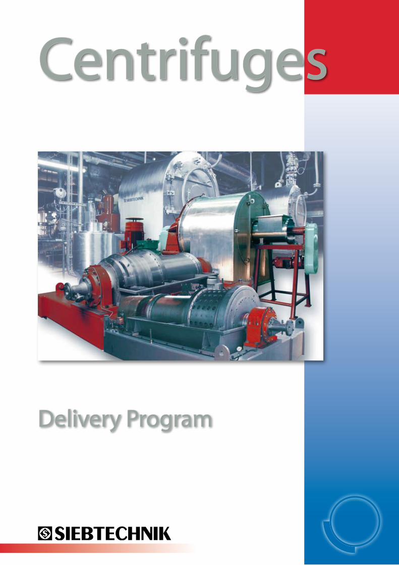
Centrifuges
Delivery Program
2
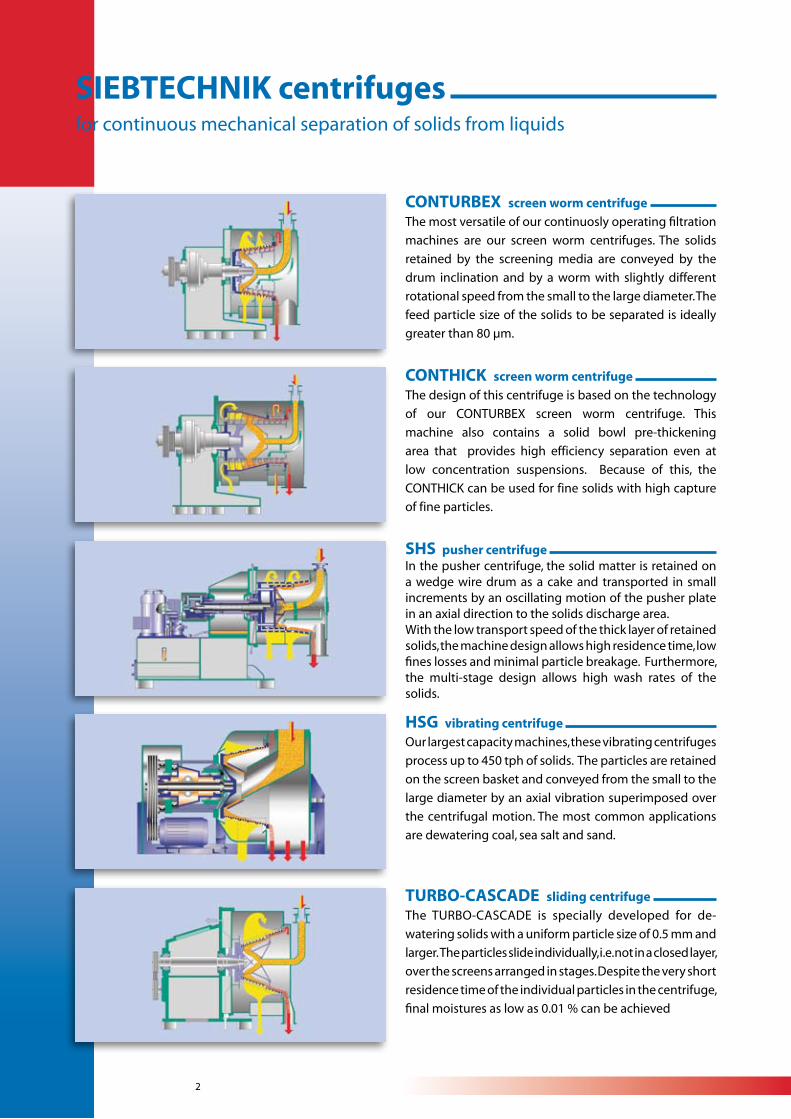
CONTURBEX screen worm centrifuge
The most versatile of our continuosly operating filtration
machines are our screen worm centrifuges. The solids
retained by the screening media are conveyed by the
drum inclination and by a worm with slightly different
rotational speed from the small to the large diameter. The
feed particle size of the solids to be separated is ideally
greater than 80 µm.
SIEBTECHNIK centrifuges for continuous mechanical separation of solids from liquids
SHS pusher centrifuge In the pusher centrifuge, the solid matter is retained on a wedge wire drum as a cake and transported in small increments by an oscillating motion of the pusher plate in an axial direction to the solids discharge area.With the low transport speed of the thick layer of retained solids, the machine design allows high residence time, low fines losses and minimal particle breakage. Furthermore, the multi-stage design allows high wash rates of the solids.
TURBO-CASCADE sliding centrifuge
The TURBO-CASCADE is specially developed for de-
watering solids with a uniform particle size of 0.5 mm and
larger. The particles slide individually, i.e. not in a closed layer,
over the screens arranged in stages. Despite the very short
residence time of the individual particles in the centrifuge,
final moistures as low as 0.01 % can be achieved
HSG vibrating centrifuge Our largest capacity machines, these vibrating centrifuges
process up to 450 tph of solids. The particles are retained
on the screen basket and conveyed from the small to the
large diameter by an axial vibration superimposed over
the centrifugal motion. The most common applications
are dewatering coal, sea salt and sand.
CONTHICK screen worm centrifuge
The design of this centrifuge is based on the technology
of our CONTURBEX screen worm centrifuge. This
machine also contains a solid bowl pre-thickening
area that provides high efficiency separation even at
low concentration suspensions. Because of this, the
CONTHICK can be used for fine solids with high capture
of fine particles.
3
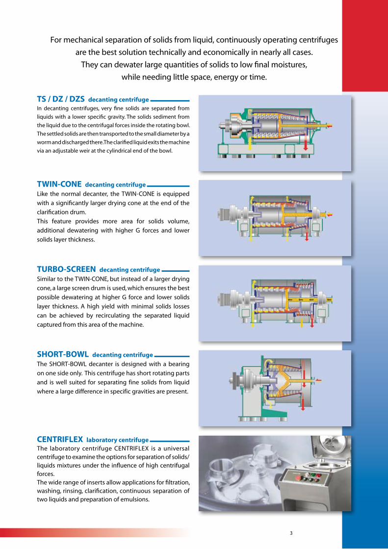
TS / DZ / DZS decanting centrifuge In decanting centrifuges, very fine solids are separated from
liquids with a lower specific gravity. The solids sediment from
the liquid due to the centrifugal forces inside the rotating bowl.
The settled solids are then transported to the small diameter by a
worm and discharged there. The clarified liquid exits the machine
via an adjustable weir at the cylindrical end of the bowl.
For mechanical separation of solids from liquid, continuously operating centrifuges
are the best solution technically and economically in nearly all cases.
They can dewater large quantities of solids to low final moistures,
while needing little space, energy or time.
TWIN-CONE decanting centrifuge
Like the normal decanter, the TWIN-CONE is equipped
with a significantly larger drying cone at the end of the
clarification drum.
This feature provides more area for solids volume,
additional dewatering with higher G forces and lower
solids layer thickness.
TURBO-SCREEN decanting centrifuge
Similar to the TWIN-CONE, but instead of a larger drying
cone, a large screen drum is used, which ensures the best
possible dewatering at higher G force and lower solids
layer thickness. A high yield with minimal solids losses
can be achieved by recirculating the separated liquid
captured from this area of the machine.
SHORT-BOWL decanting centrifuge
The SHORT-BOWL decanter is designed with a bearing
on one side only. This centrifuge has short rotating parts
and is well suited for separating fine solids from liquid
where a large difference in specific gravities are present.
CENTRIFLEX laboratory centrifuge The laboratory centrifuge CENTRIFLEX is a universal centrifuge to examine the options for separation of solids/liquids mixtures under the influence of high centrifugal forces. The wide range of inserts allow applications for filtration, washing, rinsing, clarification, continuous separation of two liquids and preparation of emulsions.
4
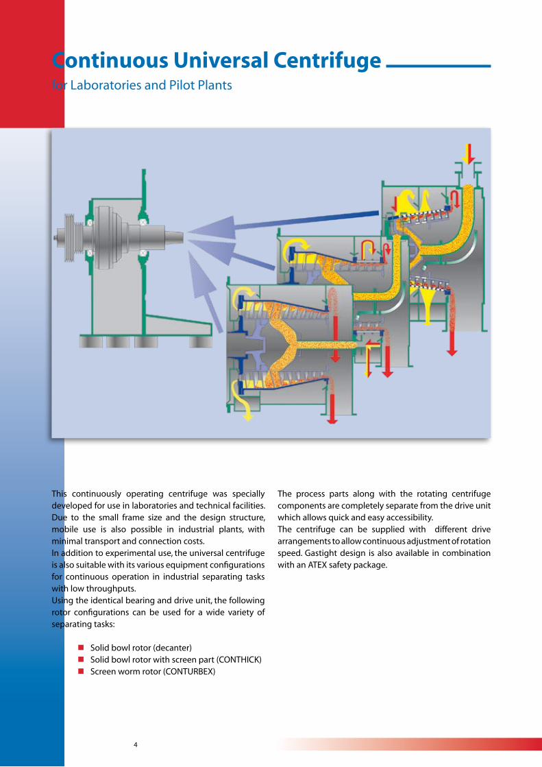
This continuously operating centrifuge was specially developed for use in laboratories and technical facilities. Due to the small frame size and the design structure, mobile use is also possible in industrial plants, with minimal transport and connection costs.In addition to experimental use, the universal centrifuge is also suitable with its various equipment configurations for continuous operation in industrial separating tasks with low throughputs.Using the identical bearing and drive unit, the following rotor configurations can be used for a wide variety of separating tasks:
nSolid bowl rotor (decanter) nSolid bowl rotor with screen part (CONTHICK) nScreen worm rotor (CONTURBEX)
The process parts along with the rotating centrifuge components are completely separate from the drive unit which allows quick and easy accessibility.The centrifuge can be supplied with different drive arrangements to allow continuous adjustment of rotation speed. Gastight design is also available in combination with an ATEX safety package.
Continuous Universal Centrifuge for Laboratories and Pilot Plants

5
DescriptionThe screen worm centrifuge consists of a drive compo-nent located in a bearing housing, the screen holding drum, the screen insert, the transport worm and the product housing enclosing the rotating parts.
The mixture of solid and liquid enters the rotating com-ponents via a central feed pipe and is deposited into the center cone of the worm body. The mixture is then accelerated and released onto the screen surface via feed ports at the small diameter of the worm body. This ensures even distribution onto the spinning drum even with fluctuations in the feed.The rotating process parts are an overhung single be-aring design. These components are typically conical design to reduce the coefficient of friction between the solids and the screen surface, allowing easier transport at the centrifugal forces.The transport worm is concentrically placed inside the screen drum. The worm flight tips have a clearance di-stance set from the screen surface at 0.5 mm to 4 mm, depending on the product and process requirements.The worm turns in the same direction as the screen drum, but at a small differential speed, and ensuring uniform acceleration of the solids. This also makes the machine very insensitive to variations in feed concentra-tion and reduces or eliminates imbalances
The feed outlet of the solid/liquid mixture inside the rotating components occurs at the smallest diameter of the drum, where the majority of the liquid is separated by the screen. Since the mixture is not subjected to high g forces in this area for dewatering, the power load required to spin the drum is much lower also resulting in decreased motor size and resulting operating cost.The feed into the smaller diameter also transmits lower mechanical action onto the solids reducing particle damage and breakage.
A distinct advantage of the screen worm centrifuge is the formation of thin layers of the solids on the screen. During travel from the small to the large diameter, the layer of solid matter remains loose and is constantly “thinning” due to the increasing surface area of the screen allowing further dewatering without high g forces.
Preferred uses are for separations with particle sizes > 80 µm.
CONTURBEX Screen worm centrifuge
6
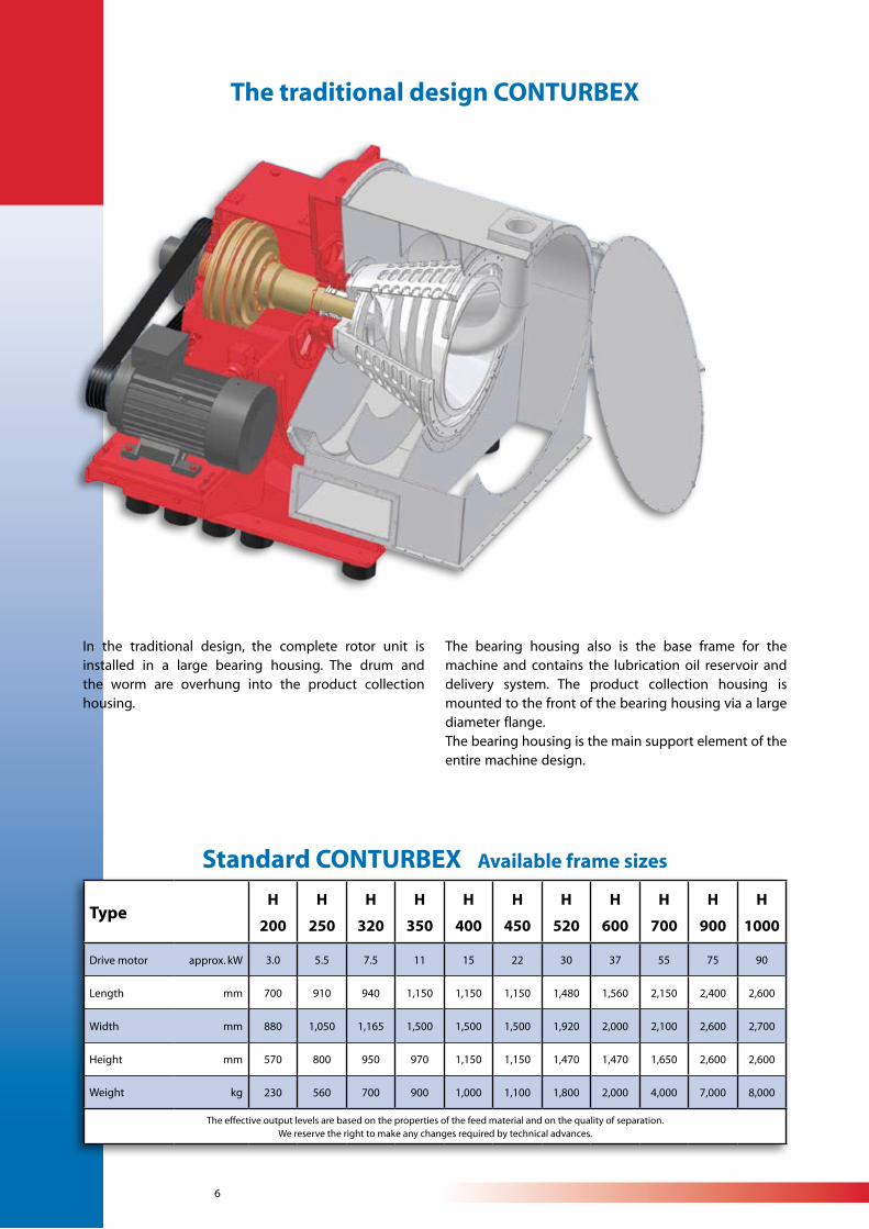
The traditional design CONTURBEX
In the traditional design, the complete rotor unit is installed in a large bearing housing. The drum and the worm are overhung into the product collection housing.
TypeH
200
H
250
H
320
H
350
H
400
H
450
H
520
H
600
H
700
H
900
H
1000
Drive motor approx. kW 3.0 5.5 7.5 11 15 22 30 37 55 75 90
Length mm 700 910 940 1,150 1,150 1,150 1,480 1,560 2,150 2,400 2,600
Width mm 880 1,050 1,165 1,500 1,500 1,500 1,920 2,000 2,100 2,600 2,700
Height mm 570 800 950 970 1,150 1,150 1,470 1,470 1,650 2,600 2,600
Weight kg 230 560 700 900 1,000 1,100 1,800 2,000 4,000 7,000 8,000
The effective output levels are based on the properties of the feed material and on the quality of separation.We reserve the right to make any changes required by technical advances.
The bearing housing also is the base frame for the machine and contains the lubrication oil reservoir and delivery system. The product collection housing is mounted to the front of the bearing housing via a large diameter flange.The bearing housing is the main support element of the entire machine design.
Standard CONTURBEX Available frame sizes
7
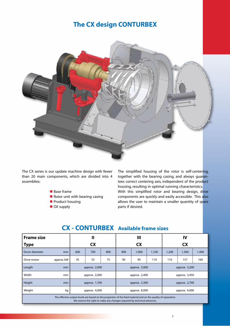
The CX design CONTURBEX
The CX series is our update machine design with fewer than 20 main components, which are divided into 4 assemblies:
n Base frame n Rotor unit with bearing casing n Product housing n Oil supply
Frame size
Type
II
CX
III
CX
IV
CX
Drum diameter mm 600 700 800 900 1,000 1,100 1,200 1,300 1,400
Drive motor approx. kW 45 55 75 90 90 110 110 137 160
Length mm approx. 2,000 approx. 3,000 approx. 3,200
Width mm approx. 2,000 approx. 2,400 approx. 3,450
Height mm approx. 1,700 approx. 2,300 approx. 2,700
Weight kg approx. 4,000 approx. 8,000 approx. 9,000
The effective output levels are based on the properties of the feed material and on the quality of separation.We reserve the right to make any changes required by technical advances.
The simplified housing of the rotor is self-centering, together with the bearing casing, and always guaran-tees correct centering axis, independent of the product housing, resulting in optimal running characteristics.With this simplified rotor and bearing design, drive components are quickly and easily accessible. This also allows the user to maintain a smaller quantity of spare parts if desired.
CX - CONTURBEX Available frame sizes
8
For the wide variety of processes and products, the Conturbex can be equipped with components to meet the specifc application requirements. In addition to vapor or gas-tight applications, the following variations are available:
General CONTURBEX design variables
Material designsAll components that come into contact with the centrifuged material can be manufactured in corrosion resistant, austenitic steel, Hastelloy, nickel, titanium, etc. based on the application.Machines for the coal and sand industries are typically manufactured entirely from carbon steel. For abrasive feed material, wear resistant materials and coatings are available for every application.
CIP cleaningEvery Conturbex centrifuge is equipped with cleaning nozzles as standard, to remove any build-up of material in the wet or dry areas of the product housing during shutdown.However, if high demands are placed on the machines, they can also be supplied with a CIP cleaning system. This includes special rinsing pipes, special nozzles and, if necessary, a slow speed drive to allow flooding of the rotating parts
ATEX design for Explosion protection zonesIn accordance with EU directive 94/9/EC (ATEX 100a), all Siebtechnik centrifuges can be equipped with an ATEX package to meet the hazard zones requirements.
Different angles of screen drum inclination, based-adjusted on the product and process:n 0° to 20°
Choice of screen designs to suit the application:n Split-screen insertsn CONIDUR® screen plate insertsn Laser screen plate insertsn Wedgewire screen
Three drive unit design possibilities are available:n Cyclo gearbox n Siebtechnik planetary gear driven Hydraulic drive unit ( variable worm rotation speed)It is also possible to supply two drive motors (drum and worm) with frequency control changing speeds.
Sealing arrangements are based on the product process and are standardized in the following designs:n open labyrinth sealsn PTFE chamber packing for vaportight designn PTFE chamber packing for gastight designn Pressure-tight design with slide ring seal
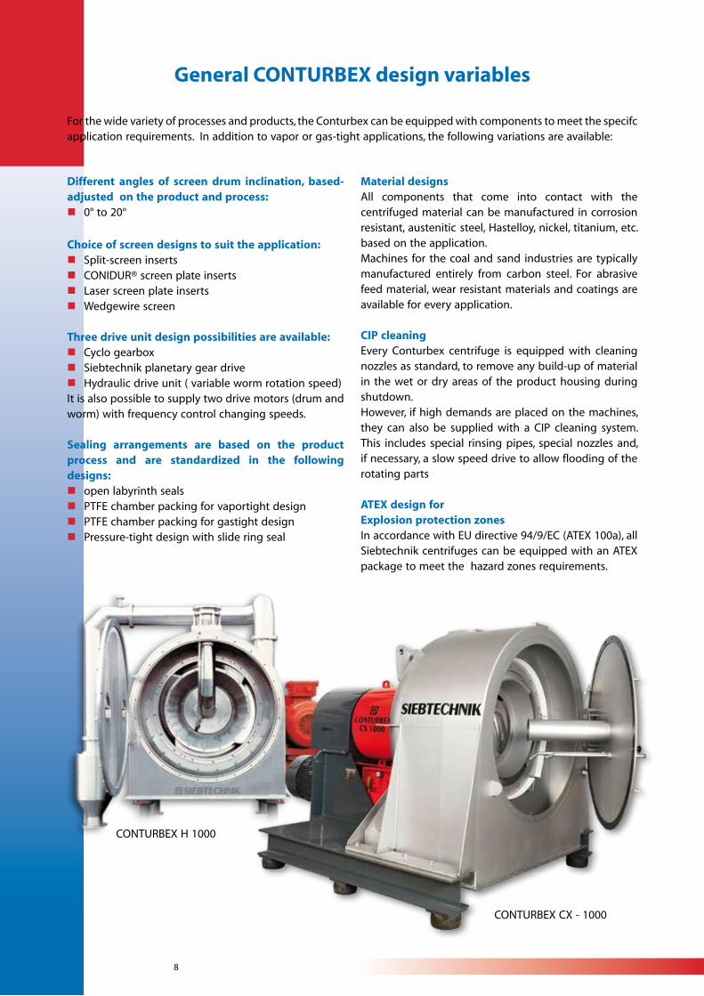
CONTURBEX H 1000
CONTURBEX CX - 1000
9
Successfully used for:Acetic acidAdipic acidAH saltAmmonium persulphateAmmonium phosphateAmmonium sulphateAmmonium thiosulphateAnimal fatsAnthraceneAspirinBisphenolBoraxCarboxymethylcellulose Citric acidCoal slurryCoffee freeze concentrateCoffee groundsCopper sulphateCotton lintersCrystal sodaDimethylterepthalate= DMT from methanolDipterexDisodium phosphateFungus myceliumGlauber saltGlycineIon exchangersIron sulphate heptahydrateLactose
Manganese sulphateMethylcelluloseMonosodium phosphateNaptha ionateNut fragmentsNylon cuttingsOnion mousseOxalic acidPalm pitsPearl polymersPlant extractsPlasterPlastic granulatePlexiglas beadsPolyethylenePolymethacrylatePolystryolPolyvinyl acetatePolyvinyl alcoholPolyvinyl chloridePotash alumPotash solvent residuePotassium bicarbonatePotassium bichromatePotassium carbonatePotassium chloridePotassium formatePotassium monochromatePotassium persulphatePotassium phosphate
Praline fragmentsPyrazoloneRegenerated rubberRock saltSilver nitrateSodium acetateSodium bisulphiteSodium carbonateSodium chlorateSodium chlorideSodium formateSodium gluconateSodium metaborateSodium nitrateSodium perborateSodium phosphateSodium sulphate (wf )Sodium sulphiteSodium tetraborateSodium thiosulphateTartaric acidTin sulphateTrisodium phosphateVegatablesZinc sulphateand many others
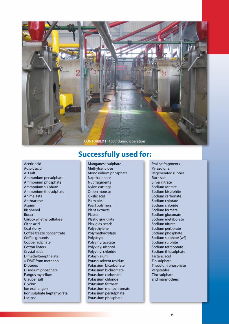
CONTURBEX H 1000 during operation

10
CONTHICK Screen worm centrifuge with pre-thickening
DescriptionThe design of this centrifuge is based on the technology of our CONTURBEX screen worm centrifuge with a pre-thickening area for high efficiency separation of low solids concentration slurry as well as high recovery of fines.The purpose of this centrifuge is to separate solids from liquids in a slurry. The slurry is fed via an inlet pipe to the pre-thickening area of the centrifuge via openings at the center in the worm body. The main liquid will be discharged at the rear of the bowl via an adjustable overflow (weir) to obtain a clean liquid separation (filtrate). The solids are pre-thickened and transported to the screening area where final dewatering and solids washing, if needed, takes place. Both liquid streams can be discharged individually or combined through a double or single filtrate discharge cyclone. The worm conveys the solid matter through the cylindrical screening section to the discharge casing.There can be a relatively small loss of solids in the screening area which can be captured by recycling back with the feed.
The centrifuge is typically supplied with a wedge wire basket. If required, a special screening plate can be used when particles sizes very fine. In either design, the screening elements can be changed very easily without disassembling the machine or removing any rotating parts.
Typical applicationsn Crystals, granulates or fibres with good sedimentation characteristicsn Particle size d´ > 0.05 mm in RRSB diagramn Solids concentration in the feed 0 - 60 % by weight
The major advantagesn Long service life of the screen elements n High yield / minimal loss of solidsn Low residual moisturen All the advantages of the overhung design: n Simple replacement of screens without disassembly n Problem-free realization of gastight design n Conversion of an existing CONTURBEX into a CONTHICK
11
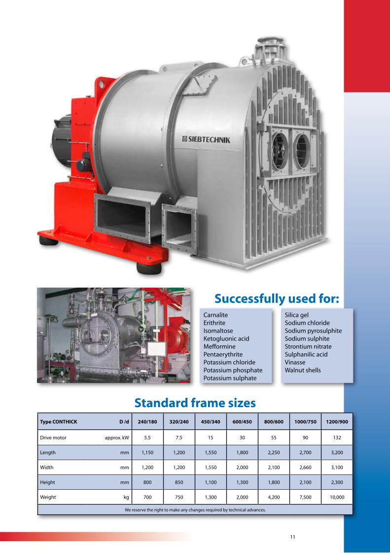
CarnaliteErithriteIsomaltoseKetogluonic acidMefforminePentaerythritePotassium chloridePotassium phosphatePotassium sulphate
Silica gelSodium chlorideSodium pyrosulphiteSodium sulphiteStrontium nitrateSulphanilic acidVinasseWalnut shells
Successfully used for:
Type CONTHICK D /d 240/180 320/240 450/340 600/450 800/600 1000/750 1200/900
Drive motor approx. kW 5.5 7.5 15 30 55 90 132
Length mm 1,150 1,200 1,550 1,800 2,250 2,700 3,200
Width mm 1,200 1,200 1,550 2,000 2,100 2,660 3,100
Height mm 800 850 1,100 1,300 1,800 2,100 2,300
Weight kg 700 750 1,300 2,000 4,200 7,500 10,000
We reserve the right to make any changes required by technical advances.
Standard frame sizes
12
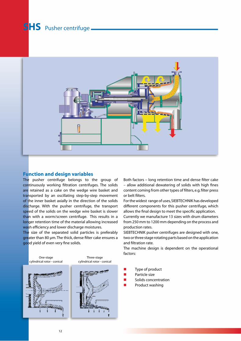
Function and design variablesThe pusher centrifuge belongs to the group of continuously working filtration centrifuges. The solids are retained as a cake on the wedge wire basket and transported by an oscillating step-by-step movement of the inner basket axially in the direction of the solids discharge. With the pusher centrifuge, the transport speed of the solids on the wedge wire basket is slower than with a worm/screen centrifuge. This results in a longer retention time of the material allowing increased wash efficiency and lower discharge moistures.The size of the separated solid particles is preferably greater than 80 µm. The thick, dense filter cake ensures a good yield of even very fine solids.
SHS Pusher centrifuge
One-stagecylindrical rotor - conical
Both factors – long retention time and dense filter cake – allow additional dewatering of solids with high fines content coming from other types of filters, e.g. filter press or belt filters. For the widest range of uses, SIEBTECHNIK has developed different components for this pusher centrifuge, which allows the final design to meet the specific application.Currently we manufacture 13 sizes with drum diameters from 250 mm to 1200 mm depending on the process and production rates. SIEBTECHNIK pusher centrifuges are designed with one, two or three stage rotating parts based on the application and filtration rate.The machine design is dependent on the operational factors:
n Type of productn Particle sizen Solids concentrationn Product washing
Three-stagecylindrical rotor - conical
13
Advantages of SIEBTECHNIK pusher centrifuges due to product requirements:
n a long residence time for the solids is required ð slow solids transport speed
n the loss of solid matter in the filtrate must be low ð thick, dense filter cake (internal filtration)
n crystal breakage and abrasion must be low ð no mechanical stress from transport elements, patented filling system
n intensive washing of the filter cake is requiredðdirect spray of the washing medium onto the cake
n high abrasion from product is expected ð low transport speed, wedgewire screen in the direction of transportation, wear resistant materials of construction or patented filling system
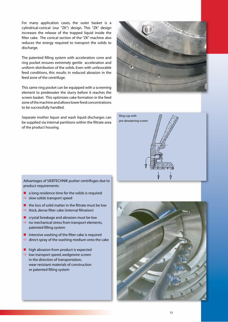
For many application cases, the outer basket is a cylindrical-conical (our “ZK”) design. This “ZK” design increases the release of the trapped liquid inside the filter cake. The conical section of the “ZK” machine also reduces the energy required to transport the solids to discharge.
The patented filling system with acceleration cone and ring pocket ensures extremely gentle acceleration and uniform distribution of the solids. Even with unfavorable feed conditions, this results in reduced abrasion in the feed zone of the centrifuge.
This same ring pocket can be equipped with a screening element to predewater the slurry before it reaches the screen basket. This optimizes cake formation in the feed zone of the machine and allows lower feed concentrations to be successfully handled.
Separate mother liquor and wash liquid discharges can be supplied via internal partitions within the filtrate area of the product housing.
Ring cup with
pre-dewatering screen
14
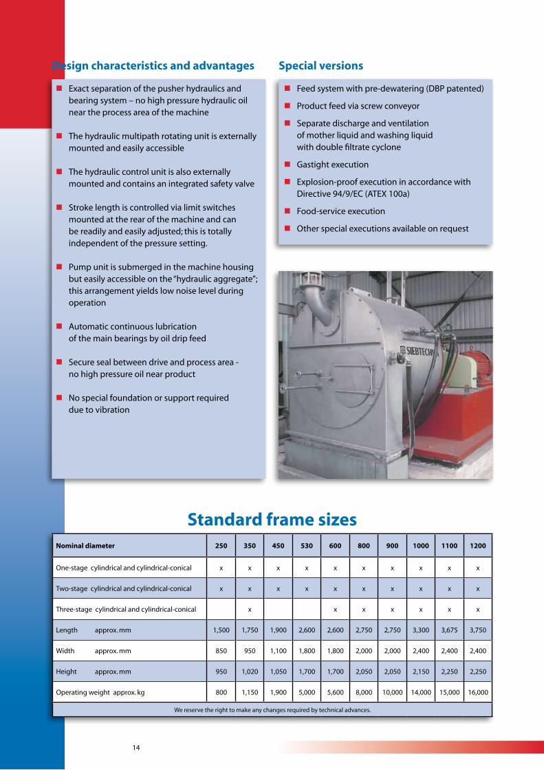
Standard frame sizesNominal diameter 250 350 450 530 600 800 900 1000 1100 1200
One-stage cylindrical and cylindrical-conical x x x x x x x x x x
Two-stage cylindrical and cylindrical-conical x x x x x x x x x x
Three-stage cylindrical and cylindrical-conical x x x x x x x
Length approx. mm 1,500 1,750 1,900 2,600 2,600 2,750 2,750 3,300 3,675 3,750
Width approx. mm 850 950 1,100 1,800 1,800 2,000 2,000 2,400 2,400 2,400
Height approx. mm 950 1,020 1,050 1,700 1,700 2,050 2,050 2,150 2,250 2,250
Operating weight approx. kg 800 1,150 1,900 5,000 5,600 8,000 10,000 14,000 15,000 16,000
We reserve the right to make any changes required by technical advances.
n Exact separation of the pusher hydraulics and bearing system – no high pressure hydraulic oil near the process area of the machine
n The hydraulic multipath rotating unit is externally mounted and easily accessible
n The hydraulic control unit is also externally mounted and contains an integrated safety valve
n Stroke length is controlled via limit switches mounted at the rear of the machine and can be readily and easily adjusted; this is totally independent of the pressure setting.
n Pump unit is submerged in the machine housing but easily accessible on the “hydraulic aggregate”; this arrangement yields low noise level during operation
n Automatic continuous lubrication of the main bearings by oil drip feed
n Secure seal between drive and process area - no high pressure oil near product
n No special foundation or support required due to vibration
n Feed system with pre-dewatering (DBP patented)
n Product feed via screw conveyor
n Separate discharge and ventilation of mother liquid and washing liquid with double filtrate cyclone
n Gastight execution
n Explosion-proof execution in accordance with Directive 94/9/EC (ATEX 100a)
n Food-service execution
n Other special executions available on request
Special versionsDesign characteristics and advantages
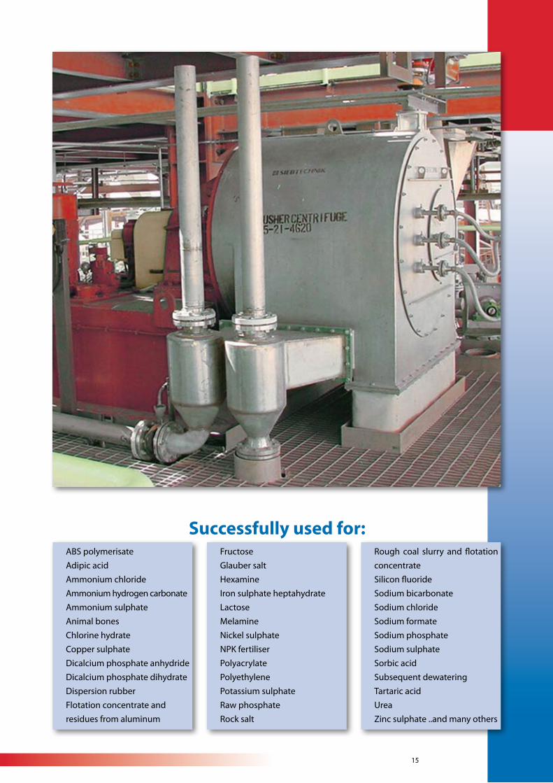
15
ABS polymerisate
Adipic acid
Ammonium chloride
Ammonium hydrogen carbonate
Ammonium sulphate
Animal bones
Chlorine hydrate
Copper sulphate
Dicalcium phosphate anhydride
Dicalcium phosphate dihydrate
Dispersion rubber
Flotation concentrate and
residues from aluminum
Fructose
Glauber salt
Hexamine
Iron sulphate heptahydrate
Lactose
Melamine
Nickel sulphate
NPK fertiliser
Polyacrylate
Polyethylene
Potassium sulphate
Raw phosphate
Rock salt
Rough coal slurry and flotation
concentrate
Silicon fluoride
Sodium bicarbonate
Sodium chloride
Sodium formate
Sodium phosphate
Sodium sulphate
Sorbic acid
Subsequent dewatering
Tartaric acid
Urea
Zinc sulphate ..and many others
Successfully used for:
16
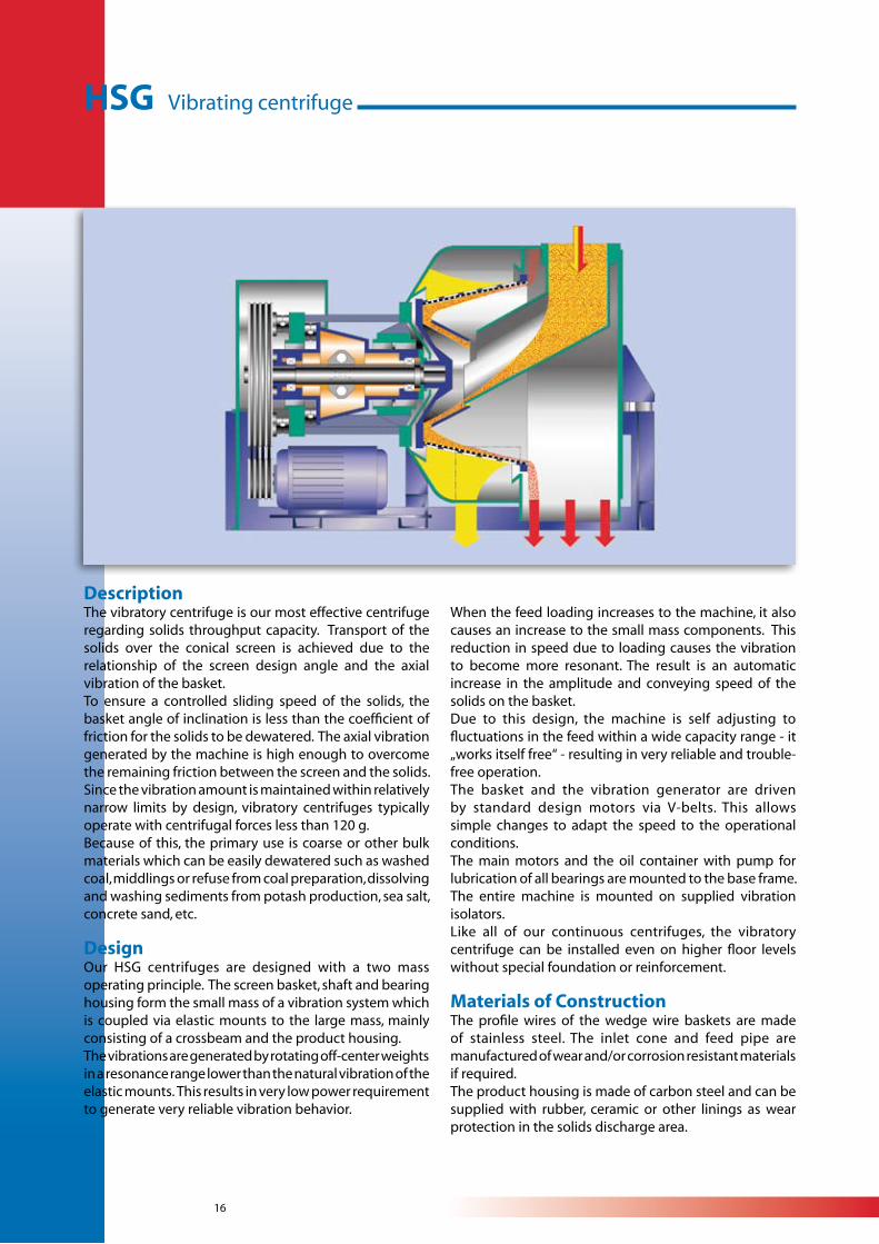
HSG Vibrating centrifuge
DescriptionThe vibratory centrifuge is our most effective centrifuge regarding solids throughput capacity. Transport of the solids over the conical screen is achieved due to the relationship of the screen design angle and the axial vibration of the basket. To ensure a controlled sliding speed of the solids, the basket angle of inclination is less than the coefficient of friction for the solids to be dewatered. The axial vibration generated by the machine is high enough to overcome the remaining friction between the screen and the solids. Since the vibration amount is maintained within relatively narrow limits by design, vibratory centrifuges typically operate with centrifugal forces less than 120 g. Because of this, the primary use is coarse or other bulk materials which can be easily dewatered such as washed coal, middlings or refuse from coal preparation, dissolving and washing sediments from potash production, sea salt, concrete sand, etc.
DesignOur HSG centrifuges are designed with a two mass operating principle. The screen basket, shaft and bearing housing form the small mass of a vibration system which is coupled via elastic mounts to the large mass, mainly consisting of a crossbeam and the product housing.The vibrations are generated by rotating off-center weights in a resonance range lower than the natural vibration of the elastic mounts. This results in very low power requirement to generate very reliable vibration behavior.
When the feed loading increases to the machine, it also causes an increase to the small mass components. This reduction in speed due to loading causes the vibration to become more resonant. The result is an automatic increase in the amplitude and conveying speed of the solids on the basket.Due to this design, the machine is self adjusting to fluctuations in the feed within a wide capacity range - it „works itself free“ - resulting in very reliable and trouble-free operation.The basket and the vibration generator are driven by standard design motors via V-belts. This allows simple changes to adapt the speed to the operational conditions. The main motors and the oil container with pump for lubrication of all bearings are mounted to the base frame. The entire machine is mounted on supplied vibration isolators.Like all of our continuous centrifuges, the vibratory centrifuge can be installed even on higher floor levels without special foundation or reinforcement.
Materials of ConstructionThe profile wires of the wedge wire baskets are made of stainless steel. The inlet cone and feed pipe are manufactured of wear and/or corrosion resistant materials if required. The product housing is made of carbon steel and can be supplied with rubber, ceramic or other linings as wear protection in the solids discharge area.
17
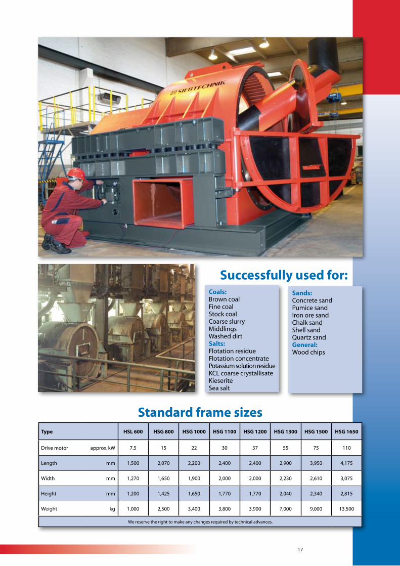
Successfully used for:
Type HSL 600 HSG 800 HSG 1000 HSG 1100 HSG 1200 HSG 1300 HSG 1500 HSG 1650
Drive motor approx. kW 7.5 15 22 30 37 55 75 110
Length mm 1,500 2,070 2,200 2,400 2,400 2,900 3,950 4,175
Width mm 1,270 1,650 1,900 2,000 2,000 2,230 2,610 3,075
Height mm 1,200 1,425 1,650 1,770 1,770 2,040 2,340 2,815
Weight kg 1,000 2,500 3,400 3,800 3,900 7,000 9,000 13,500
We reserve the right to make any changes required by technical advances.
Coals:Brown coalFine coalStock coalCoarse slurryMiddlingsWashed dirtSalts:Flotation residueFlotation concentratePotassium solution residueKCL coarse crystallisateKieseriteSea salt
Sands:Concrete sandPumice sandIron ore sand Chalk sand Shell sand Quartz sandGeneral:Wood chips
Standard frame sizes
18
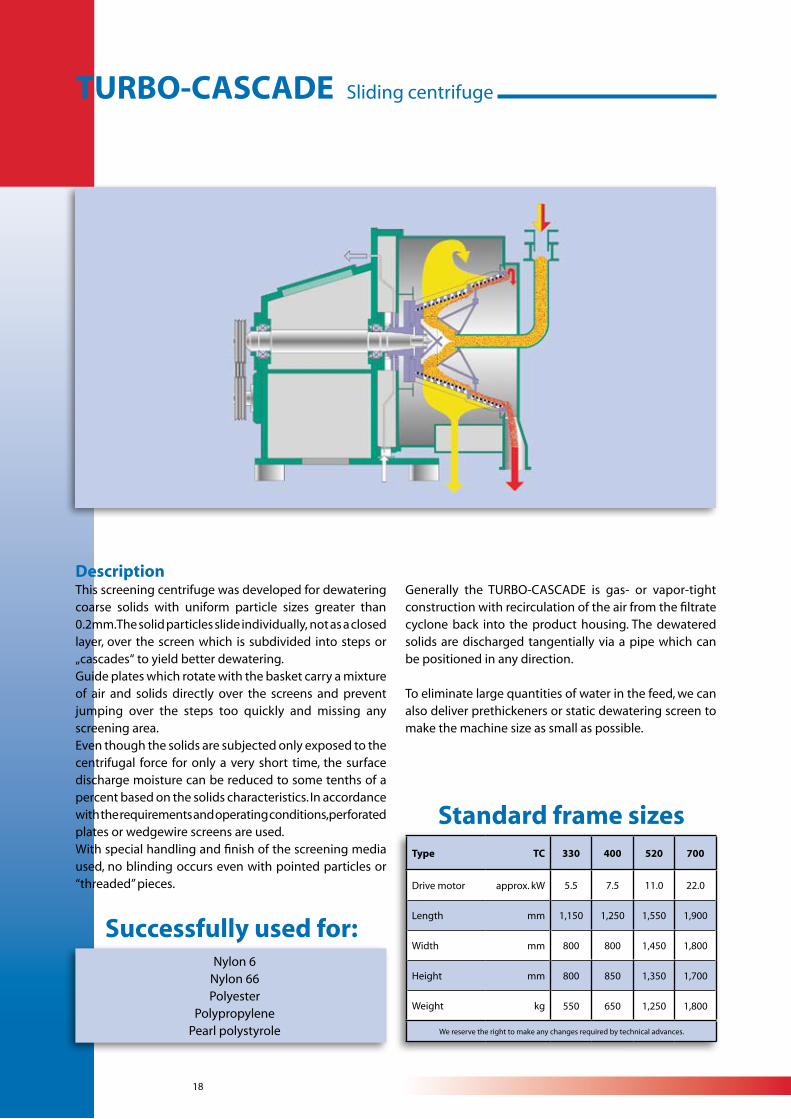
DescriptionThis screening centrifuge was developed for dewatering coarse solids with uniform particle sizes greater than 0.2mm. The solid particles slide individually, not as a closed layer, over the screen which is subdivided into steps or „cascades“ to yield better dewatering.Guide plates which rotate with the basket carry a mixture of air and solids directly over the screens and prevent jumping over the steps too quickly and missing any screening area.Even though the solids are subjected only exposed to the centrifugal force for only a very short time, the surface discharge moisture can be reduced to some tenths of a percent based on the solids characteristics. In accordance with the requirements and operating conditions, perforated plates or wedgewire screens are used.With special handling and finish of the screening media used, no blinding occurs even with pointed particles or “threaded” pieces.
Generally the TURBO-CASCADE is gas- or vapor-tight construction with recirculation of the air from the filtrate cyclone back into the product housing. The dewatered solids are discharged tangentially via a pipe which can be positioned in any direction.
To eliminate large quantities of water in the feed, we can also deliver prethickeners or static dewatering screen to make the machine size as small as possible.
Type TC 330 400 520 700
Drive motor approx. kW 5.5 7.5 11.0 22.0
Length mm 1,150 1,250 1,550 1,900
Width mm 800 800 1,450 1,800
Height mm 800 850 1,350 1,700
Weight kg 550 650 1,250 1,800
We reserve the right to make any changes required by technical advances.
Successfully used for:Nylon 6
Nylon 66Polyester
PolypropylenePearl polystyrole
Standard frame sizes
TURBO-CASCADE Sliding centrifuge
19
20
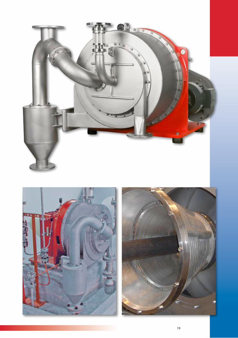
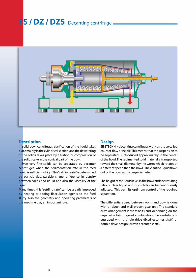
TS / DZ / DZS Decanting centrifuge
DescriptionIn solid bowl centrifuges, clarification of the liquid takes place mainly in the cylindrical section, and the dewatering of the solids takes place by filtration or compression of the solids cake in the conical part of the bowl. Even very fine solids can be separated by decanter centrifuges when the sedimentation rate in the feed liquid is sufficiently high. This “settling rate” is determined by particle size, particle shape, difference in density between solids and liquid and also the viscosity of the liquid.Many times, this “settling rate” can be greatly improved by heating or adding flocculation agents to the feed slurry. Also the geometry and operating parameters of the machine play an important role.
DesignSIEBTECHNIK decanting centrifuges work on the so called counter-flow principle. This means, that the suspension to be separated is introduced approximately in the center of the bowl. The sedimented solid material is transported toward the small diameter by the worm which rotates at a different speed than the bowl. The clarified liquid flows out of the bowl at the large diameter.
The height of the liquid level in the bowl and the resulting ratio of clear liquid and dry solids can be continuously adjusted. This permits optimum control of the required separation.
The differential speed between worm and bowl is done with a robust and well proven gear unit. The standard drive arrangement is via V-belts and, depending on the required rotating speed combination, the centrifuge is equipped with a single drive (fixed eccenter shaft) or double drive design (driven eccenter shaft).
21
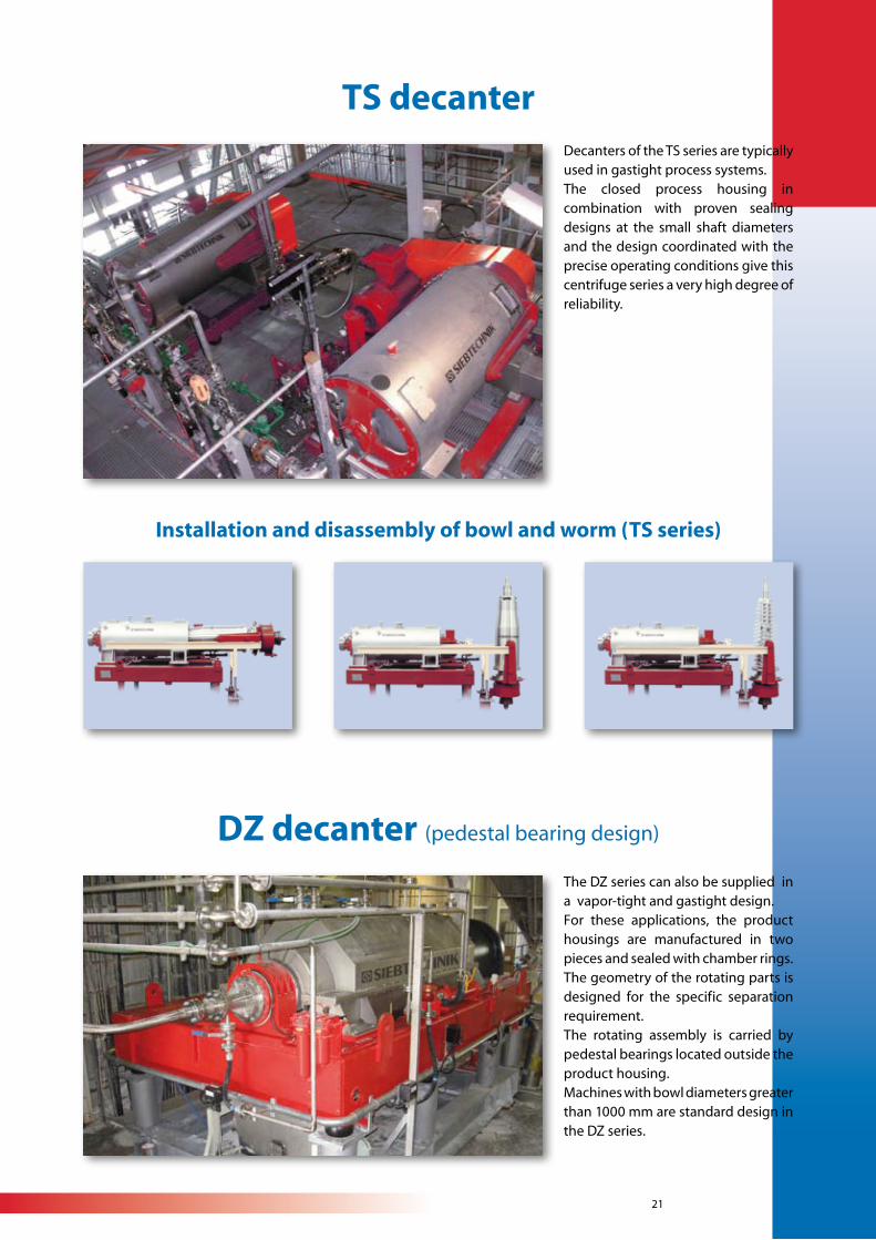
TS decanter
DZ decanter (pedestal bearing design)
Installation and disassembly of bowl and worm (TS series)
Decanters of the TS series are typically used in gastight process systems.The closed process housing in combination with proven sealing designs at the small shaft diameters and the design coordinated with the precise operating conditions give this centrifuge series a very high degree of reliability.
The DZ series can also be supplied in a vapor-tight and gastight design.For these applications, the product housings are manufactured in two pieces and sealed with chamber rings. The geometry of the rotating parts is designed for the specific separation requirement.The rotating assembly is carried by pedestal bearings located outside the product housing.Machines with bowl diameters greater than 1000 mm are standard design in the DZ series.
22
Type 210 300 360 420 500 600 710 8501000(DZ)
1100(DZ)
1200(DZ)
Drive motorapprox.
kW5.5 - 11 10 - 22 18.5 - 30 18.5 - 45 22 - 50 30 - 90 45 - 110 55 - 160 120 - 200 132 - 315 200 - 250
Length TS / DZapprox.
mm1,400 1,900 2,020 2,200 2,650 2,900 3,300 3,500 4,570 4,770 5,060
Length TSE / DZEapprox.
mm1,700 2,200 2,380 2,620 3,150 3,500 4,010 4,000 5,370 5,870 6,260
Length TSL / DZLapprox.
mm2,000 2,500 2,740 3,040 3,650 4,100 4,720 5,200 6,570 6,970 7,460
widthTS, TSE, TSL
DZ, DZE, DZL
approx.
mm1,100 1,370 1,500 1,750 2,035 2,060 2,580 2,700 3,160 3,260 3,600
HeightTS, TSE, TSL
DZ, DZE, DZL
approx.
mm750 940 980 1,110 1,325 1,400 1,450 1,600 1,660 1,750 1,915
Weight TSapprox.
kg900 1,200 1,500 2,100 3,000 4,200 5,000 7,000 10,000 12,800 20,500
Weight TSEapprox.
kg1,200 1,400 1,800 2,450 3,500 5,000 6,000 8,300 12,000 15,500 23,000
Weight TSLapprox.
kg1,400 1,600 2,100 2,800 4,000 5,800 7,000 9,800 15,000 18,300 25,500
We reserve the right to make any changes required by technical advances.
Decanter standard frame sizes DZ/TS series
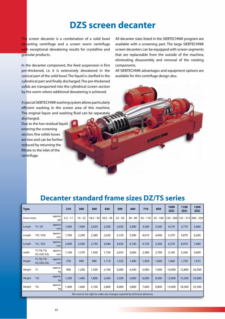
The screen decanter is a combination of a solid bowl
decanting centrifuge and a screen worm centrifuge
with exceptional dewatering results for crystalline and
granular products.
In the decanter component, the feed suspension is first
pre-thickened, i.e. it is extensively dewatered in the
conical part of the solid bowl. The liquid is clarified in the
cylindrical part and finally discharged. The pre-thickened
solids are transported into the cylindrical screen section
by the worm where additional dewatering is achieved.
A special SIEBTECHNIK washing system allows particularly
efficient washing in the screen area of this machine.
The original liquor and washing fluid can be separately
discharged.
Due to the low residual liquid
entering the screening
section, fine solids losses
are low and can be further
reduced by returning the
filtrate to the inlet of the
centrifuge.
DZS screen decanterAll decanter sizes listed in the SIEBTECHNIK program are
available with a screening part. The large SIEBTECHNIK
screen decanters can be equipped with screen segments
that are replaceable from the outside of the machine,
eliminating disassembly and removal of the rotating
components.
All SIEBTECHNIK advantages and equipment options are
available for this centrifuge design also.
23
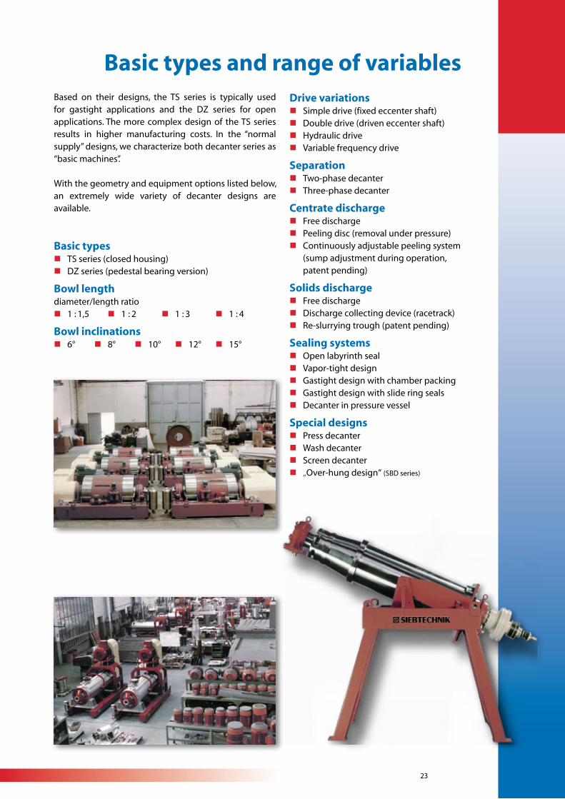
Based on their designs, the TS series is typically used for gastight applications and the DZ series for open applications. The more complex design of the TS series results in higher manufacturing costs. In the “normal supply” designs, we characterize both decanter series as “basic machines”.
With the geometry and equipment options listed below, an extremely wide variety of decanter designs are available.
Basic typesn TS series (closed housing)n DZ series (pedestal bearing version)
Bowl lengthdiameter/length ratio n 1 : 1,5 n 1 : 2 n 1 : 3 n 1 : 4
Bowl inclinations n 6° n 8° n 10° n 12° n 15°
Drive variations n Simple drive (fixed eccenter shaft)n Double drive (driven eccenter shaft)n Hydraulic driven Variable frequency drive
Separation n Two-phase decantern Three-phase decanter
Centrate discharge n Free dischargen Peeling disc (removal under pressure)n Continuously adjustable peeling system (sump adjustment during operation, patent pending)
Solids dischargen Free dischargen Discharge collecting device (racetrack)n Re-slurrying trough (patent pending)
Sealing systemsn Open labyrinth sealn Vapor-tight design n Gastight design with chamber packingn Gastight design with slide ring sealsn Decanter in pressure vessel
Special designsn Press decantern Wash decantern Screen decantern „Over-hung design“ (SBD series)
Basic types and range of variables
24
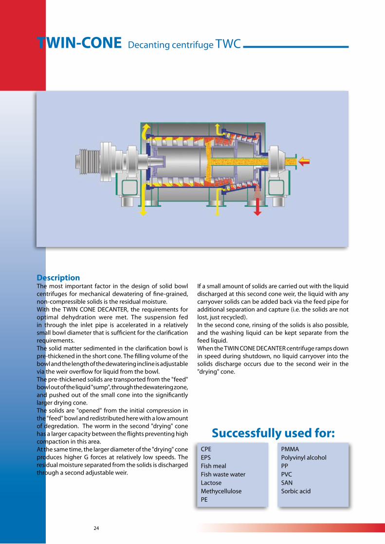
DescriptionThe most important factor in the design of solid bowl centrifuges for mechanical dewatering of fine-grained, non-compressible solids is the residual moisture.With the TWIN CONE DECANTER, the requirements for optimal dehydration were met. The suspension fed in through the inlet pipe is accelerated in a relatively small bowl diameter that is sufficient for the clarification requirements. The solid matter sedimented in the clarification bowl is pre-thickened in the short cone. The filling volume of the bowl and the length of the dewatering incline is adjustable via the weir overflow for liquid from the bowl.The pre-thickened solids are transported from the "feed" bowl out of the liquid "sump", through the dewatering zone, and pushed out of the small cone into the significantly larger drying cone.The solids are "opened" from the initial compression in the "feed" bowl and redistributed here with a low amount of degredation. The worm in the second "drying" cone has a larger capacity between the flights preventing high compaction in this area. At the same time, the larger diameter of the "drying" cone produces higher G forces at relatively low speeds. The residual moisture separated from the solids is discharged through a second adjustable weir.
If a small amount of solids are carried out with the liquid discharged at this second cone weir, the liquid with any carryover solids can be added back via the feed pipe for additional separation and capture (i.e. the solids are not lost, just recycled).In the second cone, rinsing of the solids is also possible, and the washing liquid can be kept separate from the feed liquid.When the TWIN CONE DECANTER centrifuge ramps down in speed during shutdown, no liquid carryover into the solids discharge occurs due to the second weir in the "drying" cone.
CPEEPSFish mealFish waste waterLactoseMethycellulosePE
PMMAPolyvinyl alcoholPPPVCSANSorbic acid
Successfully used for:
TWIN-CONE Decanting centrifuge TWC
25
Type TWC 250/360 350/450 450/600 600/750 750/900 800/1000 1000/1200
Drive motor approx. kW 22 45 90 132 160 200 250
Length approx. mm 2,500 2,800 3,150 3,350 4,000 4,200 4,600
Width approx. mm 1,800 1,850 2,300 2,500 2,800 3,000 3,250
Height approx. mm 920 1,020 1,300 1,500 1,800 1,900 2,100
Weight approx. kg 1,900 2,650 4,500 7,000 11,500 13,500 18,000
We reserve the right to make any changes required by technical advances.
Standard frame sizes
The 10 major advantagesn Clarification and drying in two separately designed
and differently proportioned bowl units.n Separate and therefore optimum adjustments of the
sump levels for clarification and drying. n Solids loading between the worm flights allows for
the liquid to escape, eliminating the “pull up” of liquid by an advancing worm design. This allows the use of the proven heavy-duty CYCLO gear drive for the differential speed between the bowl and worm.
n The solids are thickened into a cake in the first cone, then loosened and opened by passing over into the second cone for further dewatering.
n At high solids capacities, the second drying cone provides a larger volume and lower loading between the worm flights.
nNo liquid carry-over from the bowl into the solids discharge area during slow down/shut down.
n Optimum removal of residual liquids from the thickened solids cake in the second, higher G force and high volume drying cone.
n The separation of the large liquid loading is achieved in the first smaller bowl. As the diameter is proportional to the square of the required power at a specific acceleration, this results in lower power to drive and significant energy savings.
n Optional washing of the solids is possible in the separate second "drying" cone, with separate discharge of the wash liquid from the original liquid.
n No negative compromise between the clarification and drying.
26
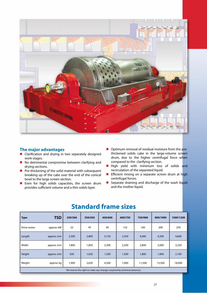
TURBO-SCREEN Decanting centrifuge TSD
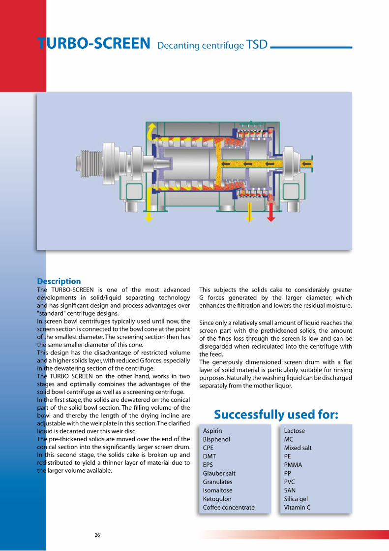
DescriptionThe TURBO-SCREEN is one of the most advanced developments in solid/liquid separating technology and has significant design and process advantages over "standard" centrifuge designs.In screen bowl centrifuges typically used until now, the screen section is connected to the bowl cone at the point of the smallest diameter. The screening section then has the same smaller diameter of this cone. This design has the disadvantage of restricted volume and a higher solids layer, with reduced G forces, especially in the dewatering section of the centrifuge.The TURBO SCREEN on the other hand, works in two stages and optimally combines the advantages of the solid bowl centrifuge as well as a screening centrifuge.In the first stage, the solids are dewatered on the conical part of the solid bowl section. The filling volume of the bowl and thereby the length of the drying incline are adjustable with the weir plate in this section. The clarified liquid is decanted over this weir disc.The pre-thickened solids are moved over the end of the conical section into the significantly larger screen drum. In this second stage, the solids cake is broken up and redistributed to yield a thinner layer of material due to the larger volume available.
This subjects the solids cake to considerably greater G forces generated by the larger diameter, which enhances the filtration and lowers the residual moisture.
Since only a relatively small amount of liquid reaches the screen part with the prethickened solids, the amount of the fines loss through the screen is low and can be disregarded when recirculated into the centrifuge with the feed.The generously dimensioned screen drum with a flat layer of solid material is particularly suitable for rinsing purposes. Naturally the washing liquid can be discharged separately from the mother liquor.
AspirinBisphenolCPEDMTEPSGlauber salt GranulatesIsomaltoseKetogulonCoffee concentrate
LactoseMCMixed saltPEPMMAPPPVCSANSilica gelVitamin C
Successfully used for:
27
Type TSD 250/360 350/450 450/600 600/750 750/900 800/1000 1000/1200
Drive motor approx. kW 22 45 90 132 160 200 250
Length approx. mm 2,500 2,800 3,150 3,350 4,000 4,200 4,600
Width approx. mm 1,800 1,850 2,300 2,500 2,800 3,000 3,250
Height approx. mm 920 1,020 1,300 1,500 1,800 1,900 2,100
Weight approx. kg 1,900 2,650 4,500 7,000 11,500 13,500 18,000
We reserve the right to make any changes required by technical advances.
Standard frame sizes
The major advantagesn Clarification and drying in two separately designed
work stages.n No detrimental compromise between clarifying and
drying sections.n Pre-thickening of the solid material with subsequent
breaking up of the cake over the end of the conical bowl to the large screen section.
n Even for high solids capacities, the screen drum provides sufficient volume and a thin solids layer.
n Optimum removal of residual moisture from the pre-thickened solids cake in the large-volume screen drum, due to the higher centrifugal force when compared to the clarifying section.
n High yield with minimum loss of solids and recirculation of the separated liquid.
n Efficient rinsing on a separate screen drum at high centrifugal forces.
n Separate draining and discharge of the wash liquid and the mother liquid.
28
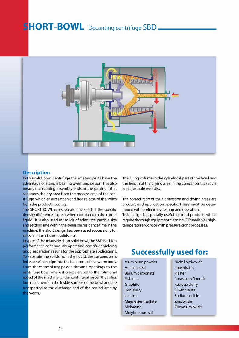
DescriptionIn this solid bowl centrifuge the rotating parts have the advantage of a single bearing overhung design. This also means the rotating assembly ends at the partition that separates the dry area from the process area of the cen-trifuge, which ensures open and free release of the solids from the product housing.The SHORT BOWL can separate fine solids if the specific density difference is great when compared to the carrier liquid. It is also used for solids of adequate particle size and settling rate within the available residence time in the machine. The short design has been used successfully for classification of some solids also.In spite of the relatively short solid bowl, the SBD is a high performance continuously operating centrifuge yielding good separation results for the appropriate applications.To separate the solids from the liquid, the suspension is fed via the inlet pipe into the feed cone of the worm body. From there the slurry passes through openings to the centrifuge bowl where it is accelerated to the rotational speed of the machine. Under centrifugal forces, the solids form sediment on the inside surface of the bowl and are transported to the discharge end of the conical area by the worm.
The filling volume in the cylindrical part of the bowl and the length of the drying area in the conical part is set via an adjustable weir disc.
The correct ratio of the clarification and drying areas are product and application specific. These must be deter-mined with preliminary testing and operation.This design is especially useful for food products which require thorough equipment cleaning (CIP available), high-temperature work or with pressure-tight processes.
Aluminium powder
Animal meal
Barium carbonate
Fish meal
Graphite
Iron slurry
Lactose
Magnesium sulfate
Melamine
Molybdenum salt
Nickel hydroxide
Phosphates
Plaster
Potassium fluoride
Residue slurry
Silver nitrate
Sodium iodide
Zinc oxide
Zirconium oxide
Successfully used for:
SHORT-BOWL Decanting centrifuge SBD
29
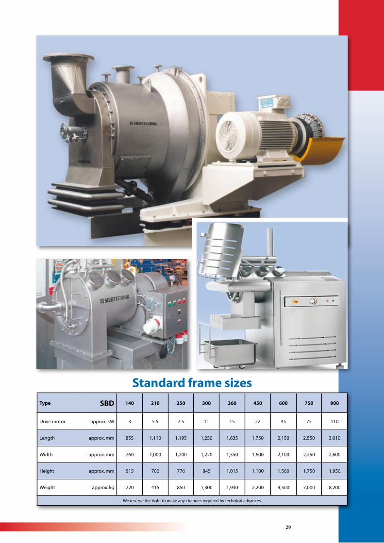
Type SBD 140 210 250 300 360 450 600 750 900
Drive motor approx. kW 3 5.5 7.5 11 15 22 45 75 110
Length approx. mm 855 1,110 1,195 1,250 1,635 1,750 2,150 2,550 3,010
Width approx. mm 760 1,000 1,200 1,220 1,550 1,600 2,100 2,250 2,600
Height approx. mm 515 700 776 845 1,015 1,100 1,560 1,750 1,950
Weight approx. kg 220 415 850 1,300 1,930 2,200 4,500 7,000 8,200
We reserve the right to make any changes required by technical advances.
Standard frame sizes
30
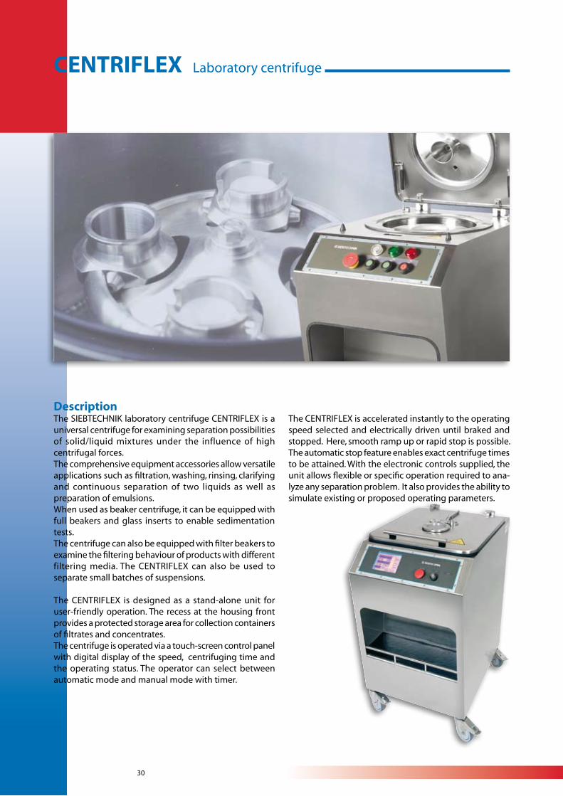
DescriptionThe SIEBTECHNIK laboratory centrifuge CENTRIFLEX is a universal centrifuge for examining separation possibilities of solid/liquid mixtures under the influence of high centrifugal forces.The comprehensive equipment accessories allow versatile applications such as filtration, washing, rinsing, clarifying and continuous separation of two liquids as well as preparation of emulsions.When used as beaker centrifuge, it can be equipped with full beakers and glass inserts to enable sedimentation tests.The centrifuge can also be equipped with filter beakers to examine the filtering behaviour of products with different filtering media. The CENTRIFLEX can also be used to separate small batches of suspensions.
The CENTRIFLEX is designed as a stand-alone unit for user-friendly operation. The recess at the housing front provides a protected storage area for collection containers of filtrates and concentrates.The centrifuge is operated via a touch-screen control panel with digital display of the speed, centrifuging time and the operating status. The operator can select between automatic mode and manual mode with timer.
The CENTRIFLEX is accelerated instantly to the operating speed selected and electrically driven until braked and stopped. Here, smooth ramp up or rapid stop is possible. The automatic stop feature enables exact centrifuge times to be attained. With the electronic controls supplied, the unit allows flexible or specific operation required to ana-lyze any separation problem. It also provides the ability to simulate existing or proposed operating parameters.
CENTRIFLEX Laboratory centrifuge
31
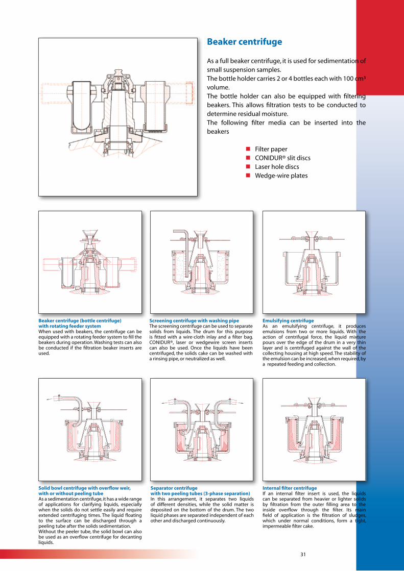
Beaker centrifuge
As a full beaker centrifuge, it is used for sedimentation of small suspension samples.The bottle holder carries 2 or 4 bottles each with 100 cm³ volume.The bottle holder can also be equipped with filtering beakers. This allows filtration tests to be conducted to determine residual moisture.The following filter media can be inserted into the beakers
n Filter paper n CONIDUR® slit discs n Laser hole discs n Wedge-wire plates
Beaker centrifuge (bottle centrifuge)with rotating feeder systemWhen used with beakers, the centrifuge can be equipped with a rotating feeder system to fill the beakers during operation. Washing tests can also be conducted if the filtration beaker inserts are used.
Screening centrifuge with washing pipeThe screening centrifuge can be used to separate solids from liquids. The drum for this purpose is fitted with a wire-cloth inlay and a filter bag. CONIDUR®, laser or wedgewire screen inserts can also be used. Once the liquids have been centrifuged, the solids cake can be washed with a rinsing pipe, or neutralized as well.
Emulsifying centrifugeAs an emulsifying centrifuge, it produces emulsions from two or more liquids. With the action of centrifugal force, the liquid mixture pours over the edge of the drum in a very thin layer and is centrifuged against the wall of the collecting housing at high speed. The stability of the emulsion can be increased, when required, by a repeated feeding and collection.
Solid bowl centrifuge with overflow weir,with or without peeling tubeAs a sedimentation centrifuge, it has a wide range of applications for clarifying liquids, especially when the solids do not settle easily and require extended centrifuging times. The liquid floating to the surface can be discharged through a peeling tube after the solids sedimentation.Without the peeler tube, the solid bowl can also be used as an overflow centrifuge for decanting liquids.
Separator centrifugewith two peeling tubes (3-phase separation)In this arrangement, it separates two liquids of different densities, while the solid matter is deposited on the bottom of the drum. The two liquid phases are separated independent of each other and discharged continuously.
Internal filter centrifugeIf an internal filter insert is used, the liquids can be separated from heavier or lighter solids by filtration from the outer filling area to the inside overflow through the filter. Its main field of application is the filtration of sludges, which under normal conditions, form a tight, impermeable filter cake.
WB
21
0E
/0
4.
20
08SIEBTECHNIK GmbH
Platanenallee 4645478 Mülheim an der Ruhr
GermanyPhone ........... +49 (0)208 / 58 01 - 00Fax .................. +49 (0)208 / 58 01 - 300e-mai l : sa les@siebtechnik .comwebsite : www.siebtechnik .com
Delivery Program
Screening Machines Process Equipmentcircular and elliptical motion screens
double counterweight screens
round screens
jigs
Sample TakingSize Reduction MachinesLaboratory Equipmentindividual units and complete installations
for sample taking and preparation
jaw crushers
roller mills
hammer and hammer impact mills
vibrating mills and ball mills
rotary shredders
test grading machines
analytical screening machines
dividers
testing drums
Centrifugesscreen worm centrifuges
pusher centrifuges
sliding discharge centrifuges
vibrating centrifuges
decanter centrifuges