centrifuge 5804/5804 r/5810/5810 r - operating manual · centrifuge 5804/5804 r/5810/5810 r —...
TRANSCRIPT
Centrifuge 5804/5804 R/5810/5810 R Operating manual
Bruksanvisning
Copyright© 2012 Eppendorf AG, Hamburg. No part of this publication may be reproduced without the prior permission of
the copyright owner.
Trademarks
eppendorf and CombiSlide are registered trademarks of Eppendorf AG, Hamburg, Germany.
Centriplus is a registered trademark of Millipore Corporation, Billerica, USA.
Microtainer is a registered trademark of Becton Dickinson, Franklin Lakes, NJ, USA.
Trademarks are not marked in all cases with ™ or ® in this manual.
5820 900.059-01/072012
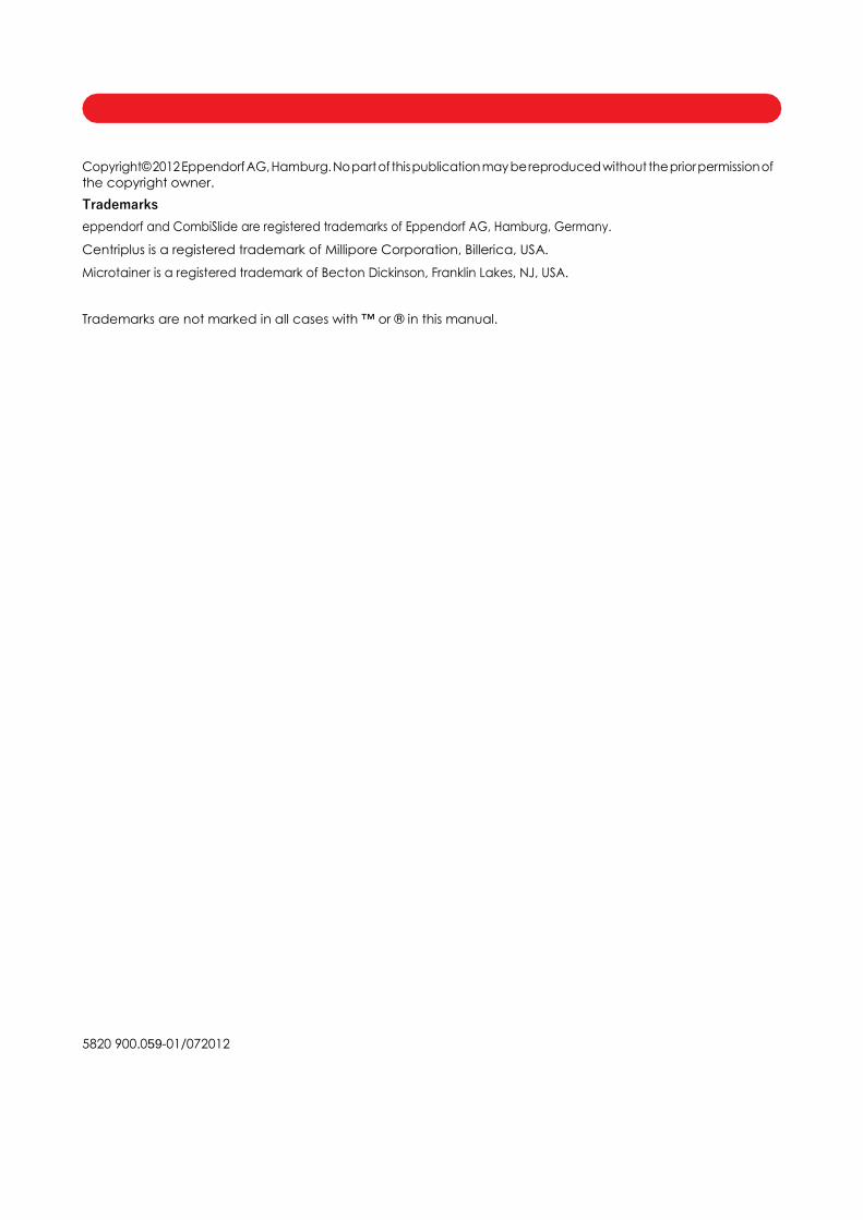
You will find a detailed description of these figures in your language in Chapters 2.1 and 5.1.
1 Centrifuge lid 2 Monitoring glass
3 Operator panel with display 4 Emergency release
5 Condensation water tray (only Centrifuge 5804 R/ 5810 R)
Task/function Press Display Details
Set parameter 1. Press or etc.
2. Press or .
1. Selected parameter
flashes.
2. New value appears.
Chapter 5.4.1
Soft start/stop 1. Press repeatedly.
2. Press or to select
ramp.
: Acceleration ramp 0
(long) ... 9 (short).
: Deceleration ramp 0
(long) ... 9 (short).
Chapter 6.2 (English,
German)
Alarm ON/OFF Press +
simultaneously.
Alarm on/Alarm off Chapter 6.7.2 (English,
German)
Programming
(during rotor stop only)
1. Set parameter.
2. Press 2 x .
3. Store: Press > 2 s.
1. Parameter.
2. P...: first idle program no.
3. OK
Chapters 6.4 - 6.6 (English,
German)
At set rpm
(with open centrifuge lid
only) Press > 4 s.
: : off
Chapter 6.3 (English,
German)
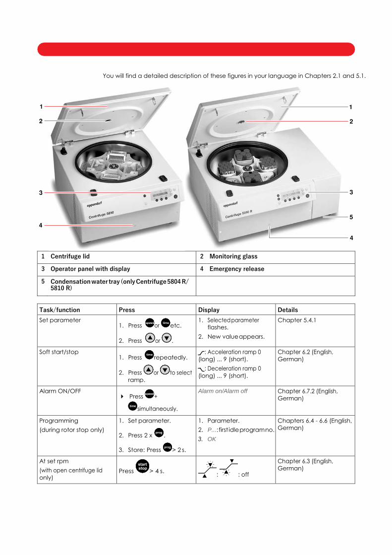
1 Short spin centrifugation 2 Display
3 Status At set rpm function 4 Indicate speed (rpm), g-force (rcf) and radius setting .
5 Symbol for acceleration and braking 6 Set parameters and values
7 Release centrifuge lid 8 Start or stop centrifugation
9 Adjust centrifugation time 10 Set centrifugation speed
11 Select or save program 12 Standby
13 Set temperature (only 5804 R/5810 R) 14 Start temperature control run FastTemp (only 5804 R/5810 R)
1 Program number 2 Symbol for g-force (rcf)
3 g-force (rcf)/rotational speed (rpm) 4 Symbol flashes when rotor is in motion
5 Symbol for acceleration and braking 6 Centrifugation time
7 Temperature (only 5804 R/5810 R)
Number of buckets
Number of bores
Aerosol-tight version
∅ of buckets (mm)
Swing-bucket rotor
∅ of bores (mm)
Angle of bores
Fixed-angle rotor
Number of buckets
Number of bores
Aerosol-tight version
∅ of buckets (mm)
81
Swing-bucket rotor
∅ of bores (mm)
Angle of bores
Fixed-angle rotor

Centrifuge 5804/5804 R/5810/5810 R — Operating manual
1 Operating instructions .............................................................................................................................................. 9
1.1 Using this manual ................................................................................................................................................... 9
1.2 Danger symbols and danger levels ................................................................................................................... 9
1.2.1 Hazard icons ........................................................................................................................................... 9
1.2.2 Degrees of danger ................................................................................................................................ 9
1.3 Symbols used .......................................................................................................................................................... 9
1.4 Abbreviations used ............................................................................................................................................. 10
2 Product description ................................................................................................................................................. 11
2.1 Main illustration .................................................................................................................................................... 11
2.2 Delivery package ................................................................................................................................................ 12
2.3 Features ................................................................................................................................................................. 12
2.4 Rotors ..................................................................................................................................................................... 13
2.4.1 Rotor A-4-81 (only 5810/5810 R) ......................................................................................................... 14
2.4.2 Rotor A-4-62 and A-4-62-MTP (only 5810/5810 R) ........................................................................... 18
2.4.3 Rotor A-4-44 ........................................................................................................................................... 22
2.4.4 Rotor A-2-DWP-AT (only 5810/5810 R) ............................................................................................... 24
2.4.5 A-2-DWP rotor ....................................................................................................................................... 25
2.4.6 Rotor FA-45-6-30 ................................................................................................................................... 26
2.4.7 Rotor F-34-6-38 ...................................................................................................................................... 28
2.4.8 Rotor FA-45-30-11 and F-45-30-11 ...................................................................................................... 29
2.4.9 Rotor F-45-48-PCR ................................................................................................................................. 30
2.4.10 Rotor T-60-11 .......................................................................................................................................... 31
2.4.11 Rotor S-4-104 (only 5810/5810 R)........................................................................................................ 31
2.4.12 Rotor S-4-72 ........................................................................................................................................... 33
2.4.13 Rotor F-35-48-17 .................................................................................................................................... 35
2.4.14 FA-45-48-11 rotor .................................................................................................................................. 35
2.4.15 Rotor FA-45-20-17 ................................................................................................................................. 36
3 Safety ........................................................................................................................................................................ 37
3.1 Intended use ........................................................................................................................................................ 37
3.2 User profile ............................................................................................................................................................ 37
3.3 Application limits ................................................................................................................................................. 37
3.3.1 Declaration concerning the ATEX directive (94/9/EC) .................................................................. 37
3.3.2 Maximum service life for accessories ............................................................................................... 37
3.4 Information on product liability ......................................................................................................................... 39
3.5 Warnings for intended use ................................................................................................................................. 39
3.5.1 Personal injury or damage to the equipment ................................................................................. 39
3.5.2 Incorrect handling of the centrifuge ................................................................................................ 40
3.5.3 Incorrect handling of the rotors ......................................................................................................... 41
3.5.4 Extreme strain on the centrifuging tubes ......................................................................................... 42
3.5.5 Aerosol-tight centrifugation ............................................................................................................... 42
3.6 Safety instructions on the device ..................................................................................................................... 43
4 Installation ................................................................................................................................................................ 44
4.1 Selecting the location ........................................................................................................................................ 44
4.2 Preparing installation .......................................................................................................................................... 44
4.3 Installing the instrument ...................................................................................................................................... 45
5 Operation .................................................................................................................................................................. 46
5.1 Overview of operating controls ........................................................................................................................ 46
5.2 Preparing for centrifugation .............................................................................................................................. 47
Table of contents
5
EN
Op
erating m
anu
al

Centrifuge 5804/5804 R/5810/5810 R — Operating manual
5.2.1 Switching on the centrifuge . . . . . . . . . . . . . . . . . . . . . . . . . . . . . . . . . . . . . . . . . . . . . . . . . . . . . . . 47
5.2.2 Inserting the rotor. . . . . . . . . . . . . . . . . . . . . . . . . . . . . . . . . . . . . . . . . . . . . . . . . . . . . . . . . . . . . . . 47
5.2.3 Automatic rotor detection . . . . . . . . . . . . . . . . . . . . . . . . . . . . . . . . . . . . . . . . . . . . . . . . . . . . . . . . . 47
5.2.4 Loading the rotor . . . . . . . . . . . . . . . . . . . . . . . . . . . . . . . . . . . . . . . . . . . . . . . . . . . . . . . . . . . . . . . 48
5.2.5 Closing the centrifuge lid . . . . . . . . . . . . . . . . . . . . . . . . . . . . . . . . . . . . . . . . . . . . . . . . . . . . . . . . . 51
5.3 Cooling (only 5804 R/5810 R) . . . . . . . . . . . . . . . . . . . . . . . . . . . . . . . . . . . . . . . . . . . . . . . . . . . . . . . . . . . . 51
5.3.1 Temperature adjustment . . . . . . . . . . . . . . . . . . . . . . . . . . . . . . . . . . . . . . . . . . . . . . . . . . . . . . . . . 51
5.3.2 Temperature display . . . . . . . . . . . . . . . . . . . . . . . . . . . . . . . . . . . . . . . . . . . . . . . . . . . . . . . . . . . . 51
5.3.3 Temperature monitoring. . . . . . . . . . . . . . . . . . . . . . . . . . . . . . . . . . . . . . . . . . . . . . . . . . . . . . . . . . 51
5.3.4 FastTemp. . . . . . . . . . . . . . . . . . . . . . . . . . . . . . . . . . . . . . . . . . . . . . . . . . . . . . . . . . . . . . . . . . . . . 51
5.3.5 Continuous cooling . . . . . . . . . . . . . . . . . . . . . . . . . . . . . . . . . . . . . . . . . . . . . . . . . . . . . . . . . . . . . 52
5.4 Centrifuging . . . . . . . . . . . . . . . . . . . . . . . . . . . . . . . . . . . . . . . . . . . . . . . . . . . . . . . . . . . . . . . . . . . . . . . . . . 53
5.4.1 Centrifuging with preset time . . . . . . . . . . . . . . . . . . . . . . . . . . . . . . . . . . . . . . . . . . . . . . . . . . . . . . 53
5.4.2 Centrifuging in continuous operation . . . . . . . . . . . . . . . . . . . . . . . . . . . . . . . . . . . . . . . . . . . . . . . . 54
5.4.3 Short spin centrifugation . . . . . . . . . . . . . . . . . . . . . . . . . . . . . . . . . . . . . . . . . . . . . . . . . . . . . . . . . 54
5.4.4 Removing the rotor . . . . . . . . . . . . . . . . . . . . . . . . . . . . . . . . . . . . . . . . . . . . . . . . . . . . . . . . . . . . . 55
5.4.5 Standby mode . . . . . . . . . . . . . . . . . . . . . . . . . . . . . . . . . . . . . . . . . . . . . . . . . . . . . . . . . . . . . . . . . 55
6 Operating controls and function . . . . . . . . . . . . . . . . . . . . . . . . . . . . . . . . . . . . . . . . . . . . . . . . . . . . . . . . . . . . . . 56
6.1 Setting the radius . . . . . . . . . . . . . . . . . . . . . . . . . . . . . . . . . . . . . . . . . . . . . . . . . . . . . . . . . . . . . . . . . . . . . . 56 6.2 Setting the acceleration and braking times. . . . . . . . . . . . . . . . . . . . . . . . . . . . . . . . . . . . . . . . . . . . . . . . . . . 56 6.3 Setting the start of run time (At set rpm). . . . . . . . . . . . . . . . . . . . . . . . . . . . . . . . . . . . . . . . . . . . . . . . . . . . . 56 6.4 Saving the program . . . . . . . . . . . . . . . . . . . . . . . . . . . . . . . . . . . . . . . . . . . . . . . . . . . . . . . . . . . . . . . . . . . . 57 6.5 Loading the program. . . . . . . . . . . . . . . . . . . . . . . . . . . . . . . . . . . . . . . . . . . . . . . . . . . . . . . . . . . . . . . . . . . . 57 6.6 Deleting the program . . . . . . . . . . . . . . . . . . . . . . . . . . . . . . . . . . . . . . . . . . . . . . . . . . . . . . . . . . . . . . . . . . . 57 6.7 Special functions. . . . . . . . . . . . . . . . . . . . . . . . . . . . . . . . . . . . . . . . . . . . . . . . . . . . . . . . . . . . . . . . . . . . . . . 58 6.7.1 Display operating hours . . . . . . . . . . . . . . . . . . . . . . . . . . . . . . . . . . . . . . . . . . . . . . . . . . . . . . . . . . 58 6.7.2 Switching on/off the warning signal . . . . . . . . . . . . . . . . . . . . . . . . . . . . . . . . . . . . . . . . . . . . . . . . . 58 6.7.3 Exiting the service functions . . . . . . . . . . . . . . . . . . . . . . . . . . . . . . . . . . . . . . . . . . . . . . . . . . . . . . 58
6.7.4 Controlling the centrifuge via the serial interface (optional) . . . . . . . . . . . . . . . . . . . . . . . . . . . . . . . 58
7 Maintenance . . . . . . . . . . . . . . . . . . . . . . . . . . . . . . . . . . . . . . . . . . . . . . . . . . . . . . . . . . . . . . . . . . . . . . . . . . . . . . . 59
7.1 Maintenance . . . . . . . . . . . . . . . . . . . . . . . . . . . . . . . . . . . . . . . . . . . . . . . . . . . . . . . . . . . . . . . . . . . . . . . . . . 59 7.2 Prepare cleaning/disinfection . . . . . . . . . . . . . . . . . . . . . . . . . . . . . . . . . . . . . . . . . . . . . . . . . . . . . . . . . . . . . 59 7.3 Cleaning/disinfection. . . . . . . . . . . . . . . . . . . . . . . . . . . . . . . . . . . . . . . . . . . . . . . . . . . . . . . . . . . . . . . . . . . . 60 7.3.1 Cleaning and disinfecting the device . . . . . . . . . . . . . . . . . . . . . . . . . . . . . . . . . . . . . . . . . . . . . . . . 61 7.3.2 Cleaning and disinfecting the rotor . . . . . . . . . . . . . . . . . . . . . . . . . . . . . . . . . . . . . . . . . . . . . . . . . 61 7.4 Additional service instructions for Centrifuge 5804 R/5810 R . . . . . . . . . . . . . . . . . . . . . . . . . . . . . . . . . . . . 62 7.5 Glass breakage. . . . . . . . . . . . . . . . . . . . . . . . . . . . . . . . . . . . . . . . . . . . . . . . . . . . . . . . . . . . . . . . . . . . . . . . 62
7.6 Decontamination before shipment . . . . . . . . . . . . . . . . . . . . . . . . . . . . . . . . . . . . . . . . . . . . . . . . . . . . . . . . . 62
8 Troubleshooting. . . . . . . . . . . . . . . . . . . . . . . . . . . . . . . . . . . . . . . . . . . . . . . . . . . . . . . . . . . . . . . . . . . . . . . . . . . . 63
8.1 Resetting the excess current switch . . . . . . . . . . . . . . . . . . . . . . . . . . . . . . . . . . . . . . . . . . . . . . . . . . . . . . . . 63 8.2 General errors. . . . . . . . . . . . . . . . . . . . . . . . . . . . . . . . . . . . . . . . . . . . . . . . . . . . . . . . . . . . . . . . . . . . . . . . . 63 8.3 Error messages . . . . . . . . . . . . . . . . . . . . . . . . . . . . . . . . . . . . . . . . . . . . . . . . . . . . . . . . . . . . . . . . . . . . . . . 64
8.4 Emergency release. . . . . . . . . . . . . . . . . . . . . . . . . . . . . . . . . . . . . . . . . . . . . . . . . . . . . . . . . . . . . . . . . . . . . 65
9 Transport, storage and disposal . . . . . . . . . . . . . . . . . . . . . . . . . . . . . . . . . . . . . . . . . . . . . . . . . . . . . . . . . . . . . . 66
9.1 Transport . . . . . . . . . . . . . . . . . . . . . . . . . . . . . . . . . . . . . . . . . . . . . . . . . . . . . . . . . . . . . . . . . . . . . . . . . . . . 66 9.2 Storage . . . . . . . . . . . . . . . . . . . . . . . . . . . . . . . . . . . . . . . . . . . . . . . . . . . . . . . . . . . . . . . . . . . . . . . . . . . . . . 66
9.3 Disposal . . . . . . . . . . . . . . . . . . . . . . . . . . . . . . . . . . . . . . . . . . . . . . . . . . . . . . . . . . . . . . . . . . . . . . . . . . . . . 66
10 Technical data . . . . . . . . . . . . . . . . . . . . . . . . . . . . . . . . . . . . . . . . . . . . . . . . . . . . . . . . . . . . . . . . . . . . . . . . . . . . . 67
10.1 Power supply . . . . . . . . . . . . . . . . . . . . . . . . . . . . . . . . . . . . . . . . . . . . . . . . . . . . . . . . . . . . . . . . . . . . . . . . . 67
10.2 Ambient conditions . . . . . . . . . . . . . . . . . . . . . . . . . . . . . . . . . . . . . . . . . . . . . . . . . . . . . . . . . . . . . . . . . . . . . 67
6
EN
Op
erat
ing
man
ual
Centrifuge 5804/5804 R/5810/5810 R — Operating manual
10.3 Weight/dimensions.............................................................................................................................................. 68
10.4 Application parameters ..................................................................................................................................... 69
11 Ordering Information ............................................................................................................................................... 71
11.1 Centrifuge 5804/5804 R ...................................................................................................................................... 71
11.2 Centrifuge 5810/5810 R ...................................................................................................................................... 71
11.3 Rotors and accessories....................................................................................................................................... 71
11.3.1 Rotor A-4-81 (only 5810/5810 R) ......................................................................................................... 71
11.3.2 Rotor A-4-62 and A-4-62-MTP (only 5810/5810 R) ........................................................................... 73
11.3.3 Rotor A-4-44 ........................................................................................................................................... 74
11.3.4 Rotor A-2-DWP-AT (only 5810/5810 R) ............................................................................................... 75
11.3.5 Rotor A-2-DWP ...................................................................................................................................... 76
11.3.6 Rotor FA-45-6-30 ................................................................................................................................... 76
11.3.7 Rotor F-34-6-38 ...................................................................................................................................... 77
11.3.8 Rotor FA-45-30-11 and Rotor F-45-30-11 ........................................................................................... 77
11.3.9 Rotor F-45-48-PCR ................................................................................................................................. 77
11.3.10 Rotor T-60-11 .......................................................................................................................................... 77
11.3.11 Rotor S-4-104 ......................................................................................................................................... 78
11.3.12 Rotor S-4-72............................................................................................................................................ 79
11.3.13 Rotor F-35-48-17 .................................................................................................................................... 80
11.3.14 Rotor FA-45-48-11 ................................................................................................................................. 80
11.3.15 Rotor FA-45-20-17 ................................................................................................................................. 81
11.3.16 Rotor F-34-6-38 ...................................................................................................................................... 81
11.3.17 Miscellaneous ....................................................................................................................................... 81
7
EN
Op
erating m
anu
al

Centrifuge 5804/5804 R/5810/5810 R — Operating manual
8
EN
Op
erat
ing
man
ual
Centrifuge 5804/5804 R/5810/5810 R — Operating manual
1.1 Using this manual
Read this operating manual completely before using the device for the first time. If required,
please also observe the instructions for use of the accessories.
This operating manual is part of the product. Thus, it must always be easily accessible.
Enclose this operating manual when transferring the device to third parties.
If this manual is lost, please request another one. You will find the current version on our
webpage www.eppendorf.com/worldwide.
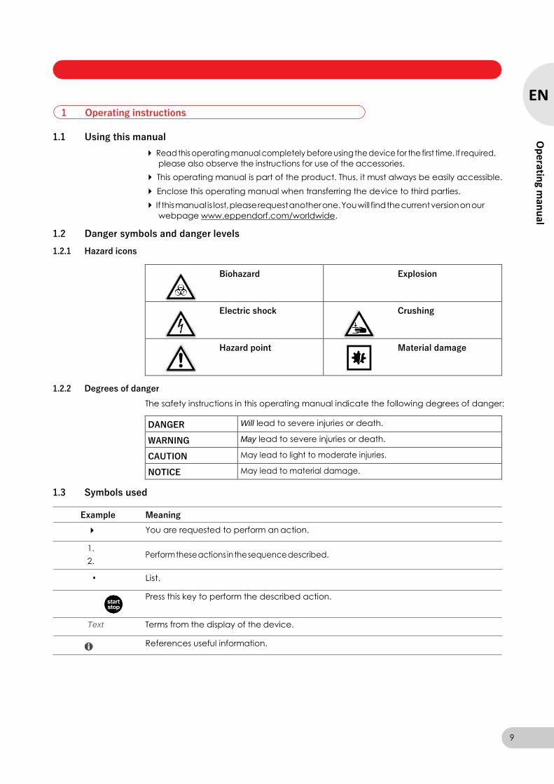
1.2 Danger symbols and danger levels
1.2.1 Hazard icons
Biohazard Explosion
Electric shock Crushing
Hazard point Material damage
1.2.2 Degrees of danger
The safety instructions in this operating manual indicate the following degrees of danger:
DANGER Will lead to severe injuries or death.
WARNING May lead to severe injuries or death.
CAUTION May lead to light to moderate injuries.
NOTICE May lead to material damage.
1.3 Symbols used
Example Meaning
You are requested to perform an action.
1. Perform these actions in the sequence described.
2.
• List.
Press this key to perform the described action.
Text Terms from the display of the device.
References useful information.
1 Operating instructions
9
EN
Op
erating m
anu
al

Centrifuge 5804/5804 R/5810/5810 R — Operating manual
1.4 Abbreviations used
MTP Micro test plate
NN Mean sea level (MSL)
PCR Polymerase chain reaction
PTFE Polytetrafluorethylene
RCF Relative centrifugal force –g-force in m/s2
rpm Revolutions per minute –in rpm
UV Ultraviolet radiation
10
EN
Op
erat
ing
man
ual
Centrifuge 5804/5804 R/5810/5810 R — Operating manual
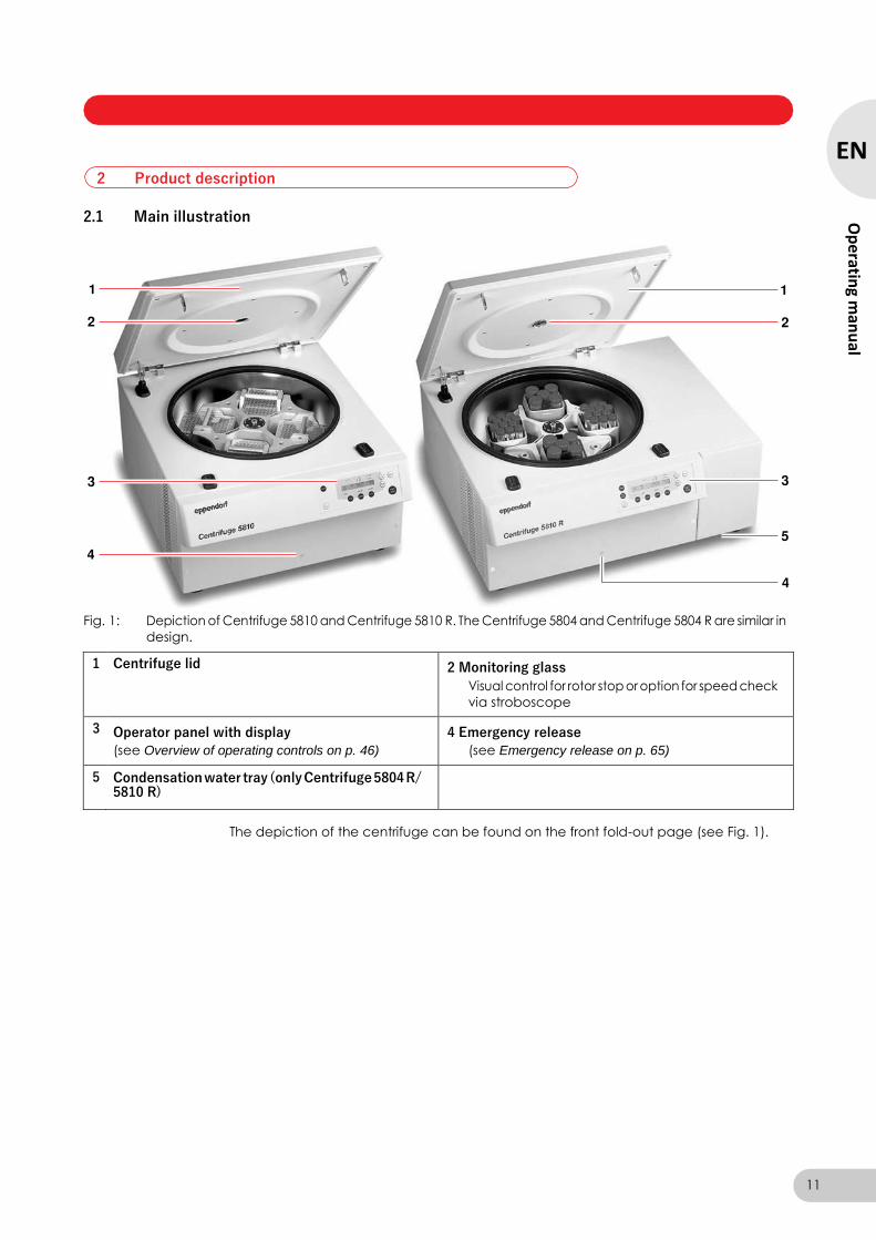
2.1 Main illustration
Fig. 1: Depiction of Centrifuge 5810 and Centrifuge 5810 R. The Centrifuge 5804 and Centrifuge 5804 R are similar in
design.
1 Centrifuge lid 2 Monitoring glass
Visual control for rotor stop or option for speed check
via stroboscope
3 Operator panel with display
(see Overview of operating controls on p. 46)
4 Emergency release
(see Emergency release on p. 65)
5 Condensation water tray (only Centrifuge 5804 R/ 5810 R)
The depiction of the centrifuge can be found on the front fold-out page (see Fig. 1).
2 Product description
11
EN
Op
erating m
anu
al
Centrifuge 5804/5804 R/5810/5810 R — Operating manual
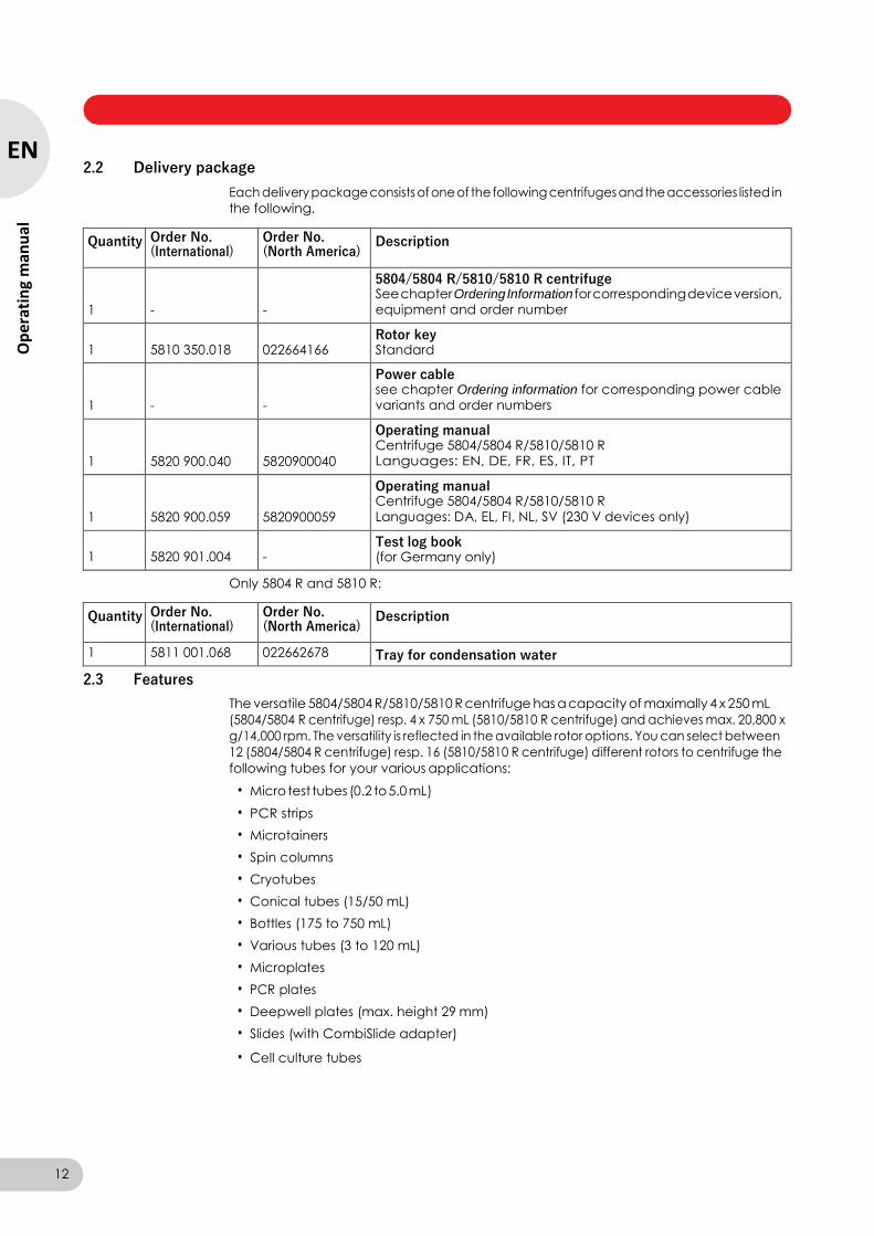
2.2 Delivery package
Each delivery package consists of one of the following centrifuges and the accessories listed in
the following.
Quantity Order No. (International)
Order No. (North America)
Description
1
-
-
5804/5804 R/5810/5810 R centrifuge See chapter Ordering Information for corresponding device version, equipment and order number
1
5810 350.018
022664166
Rotor key Standard
1
-
-
Power cable see chapter Ordering information for corresponding power cable variants and order numbers
1
5820 900.040
5820900040
Operating manual Centrifuge 5804/5804 R/5810/5810 R Languages: EN, DE, FR, ES, IT, PT
1
5820 900.059
5820900059
Operating manual Centrifuge 5804/5804 R/5810/5810 R Languages: DA, EL, FI, NL, SV (230 V devices only)
1
5820 901.004
-
Test log book (for Germany only)
Only 5804 R and 5810 R:
Quantity Order No. (International)
Order No. (North America)
Description
1 5811 001.068 022662678 Tray for condensation water
2.3 Features
The versatile 5804/5804 R/5810/5810 R centrifuge has a capacity of maximally 4 x 250 mL
(5804/5804 R centrifuge) resp. 4 x 750 mL (5810/5810 R centrifuge) and achieves max. 20,800 x
g/14,000 rpm. The versatility is reflected in the available rotor options. You can select between
12 (5804/5804 R centrifuge) resp. 16 (5810/5810 R centrifuge) different rotors to centrifuge the
following tubes for your various applications:
• Micro test tubes (0.2 to 5.0 mL)
• PCR strips
• Microtainers
• Spin columns
• Cryotubes
• Conical tubes (15/50 mL)
• Bottles (175 to 750 mL)
• Various tubes (3 to 120 mL)
• Microplates
• PCR plates
• Deepwell plates (max. height 29 mm)
• Slides (with CombiSlide adapter)
• Cell culture tubes
12
EN
Op
erat
ing
man
ual
Centrifuge 5804/5804 R/5810/5810 R — Operating manual
2.4 Rotors
Handling the centrifuge is facilitated by:
• Low access height of 29 cm for loading and unloading the rotors
• Automatic rotor detection with rotational speed limit
• Automatic rotor imbalance detection
• Clear digital display
All centrifuges in these series have 35 program spaces for user-defined settings and 10 different
acceleration and braking ramps.
Adapter-specific manual radius adjustment guarantees maximum RCF accuracy.
The Centrifuge 5804 R/5810 R has an additional temperature control function for centrifugation between -9°C and 40°C. Use the FastTemp function to start a temperature control run without samples to adjust the rotor chamber incl. rotor, buckets and adapters quickly to the set target
temperature. Continuous cooling also maintains the temperature in the rotor chamber with the
centrifuge lid closed when the centrifuge is not in use.
The built-in condensation drain eliminates water accumulation and prevents corrosion.
Eppendorf centrifuges may only be operated with rotors that are intended for use with the
corresponding centrifuge.
Only use rotors which bear the name of the centrifuge (e.g. 5804 R).
The 5804/5804 R/5810/5810 R centrifuge can be operated with the following rotors. Before use
of sample tubes, please note the recommended manufacturer's specifications with regard to the
resistance to centrifugation (max. g-force).
13
EN
Op
erating m
anu
al
Centrifuge 5804/5804 R/5810/5810 R — Operating manual
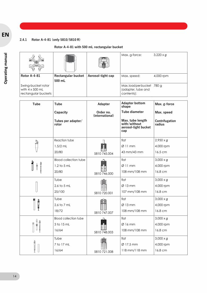
2.4.1 Rotor A-4-81 (only 5810/5810 R)
Rotor A-4-81 with 500 mL rectangular bucket
Max. g-force: 3,220 x g
Rotor A-4-81 Rectangular bucket Aerosol-tight cap Max. speed: 4,000 rpm
500 mL
Swing-bucket rotor Max. load per bucket 780 g
with 4 x 500 mL (adapter, tube and
rectangular buckets contents):
Tube Tube
Capacity
Tubes per adapter/ rotor
Adapter
Order no. (international)
Adapter bottom shape
Tube diameter
Max. tube length with/without aerosol-tight bucket cap
Max. g-force
Max. speed
Centrifugation radius
Reaction tube
1.5/2 mL
20/80
5810 745.004
flat
Ø 11 mm
43 mm/43 mm
2,950 x g
4,000 rpm
16.5 cm
Blood collection tube
1.2 to 5 mL
20/80
5810 746.000
flat
Ø 11 mm
108 mm/108 mm
3,000 x g
4,000 rpm
16.8 cm
Tube
2.6 to 5 mL
25/100
5810 720.001
flat
Ø 13 mm
107 mm/108 mm
3,000 x g
4,000 rpm
16.8 cm
Tube
2.6 to 7 mL
18/72
5810 747.007
flat
Ø 13 mm
108 mm/108 mm
3,000 x g
4,000 rpm
16.8 cm
Blood collection tube
3 to 15 mL
16/64
5810 748.003
flat
Ø 16 mm
108 mm/108 mm
3,000 x g
4,000 rpm
16.8 cm
Tube
7 to 17 mL
16/64
5810 721.008
flat
Ø 17.5 mm
118 mm/118 mm
3,000 x g
4,000 rpm
16.8 cm
14
EN
Op
erat
ing
man
ual
Centrifuge 5804/5804 R/5810/5810 R — Operating manual
Ep
pen
do
rf
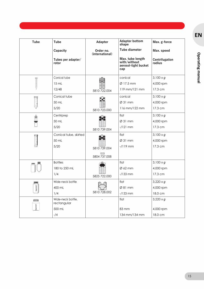
Tube Tube
Capacity
Tubes per adapter/ rotor
Adapter
Order no.
(international)
Adapter bottom shape
Tube diameter
Max. tube length with/without aerosol-tight bucket cap
Max. g-force
Max. speed
Centrifugation radius
Conical tube
15 mL
12/48
5810 722.004
conical
Ø 17.5 mm
119 mm/121 mm
3,100 x g
4,000 rpm
17.3 cm
Conical tube
5810 723.000
conical 3,100 x g
50 mL Ø 31 mm 4,000 rpm
5/20 116 mm/122 mm 17.3 cm
Centriprep
50 mL
5/20
5810 739.004
flat
Ø 31 mm
-/121 mm
3,100 x g
4,000 rpm
17.3 cm
Conical tube, skirted flat 3,100 x g
50 mL Ø 31 mm 4,000 rpm
5/20 5810 739.004
-/119 mm 17.3 cm
5804 737.008
Bottles
180 to 250 mL
1/4
5825 722.000
flat
Ø 62 mm
-/133 mm
3,100 x g
4,000 rpm
17.3 cm
Ep
pen
do
rf
Wide-neck bottle
400 mL
1/4
5810 728.002
flat
Ø 81 mm
-/133 mm
3,220 x g
4,000 rpm
18.0 cm
Wide-neck bottle,
rectangular
500 mL
-/4
- flat
83 mm
134 mm/134 mm
3,220 x g
4,000 rpm
18.0 cm
15
EN
Op
erating m
anu
al
Centrifuge 5804/5804 R/5810/5810 R — Operating manual
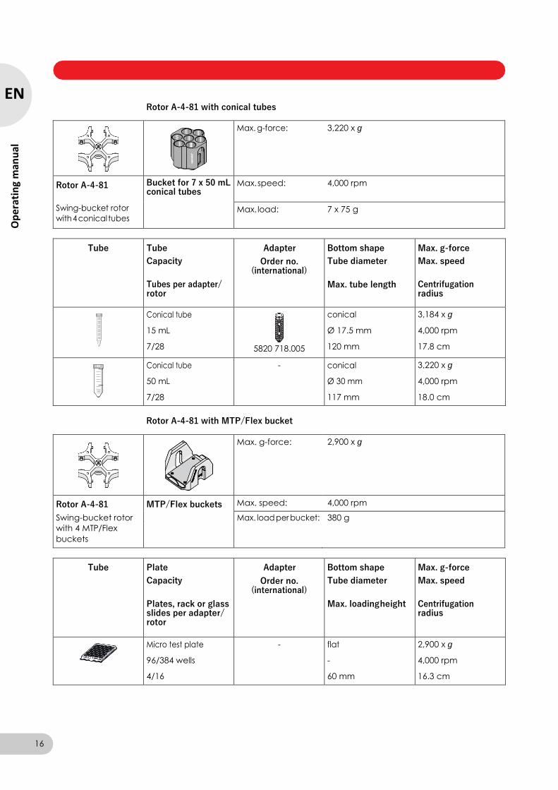
Rotor A-4-81 with conical tubes
Max. g-force: 3,220 x g
Rotor A-4-81
Swing-bucket rotor
with 4 conical tubes
Bucket for 7 x 50 mL conical tubes
Max. speed: 4,000 rpm
Max. load: 7 x 75 g
Tube Tube
Capacity
Tubes per adapter/ rotor
Adapter
Order no. (international)
Bottom shape
Tube diameter
Max. tube length
Max. g-force
Max. speed
Centrifugation radius
Conical tube
15 mL
7/28
5820 718.005
conical
Ø 17.5 mm
120 mm
3,184 x g
4,000 rpm
17.8 cm
Conical tube
50 mL
7/28
- conical
Ø 30 mm
117 mm
3,220 x g
4,000 rpm
18.0 cm
Rotor A-4-81 with MTP/Flex bucket
Max. g-force: 2,900 x g
Rotor A-4-81 MTP/Flex buckets Max. speed: 4,000 rpm
Swing-bucket rotor Max. load per bucket: 380 g
with 4 MTP/Flex
buckets
Tube Plate
Capacity
Plates, rack or glass slides per adapter/ rotor
Adapter
Order no. (international)
Bottom shape
Tube diameter
Max. loading height
Max. g-force
Max. speed
Centrifugation radius
Micro test plate
96/384 wells
4/16
- flat
-
60 mm
2,900 x g
4,000 rpm
16.3 cm
16
EN
Op
erat
ing
man
ual
Centrifuge 5804/5804 R/5810/5810 R — Operating manual
Tube Plate
Capacity
Plates, rack or glass slides per adapter/ rotor
Adapter
Order no. (international)
Bottom shape
Tube diameter
Max. loading height
Max. g-force
Max. speed
Centrifugation radius
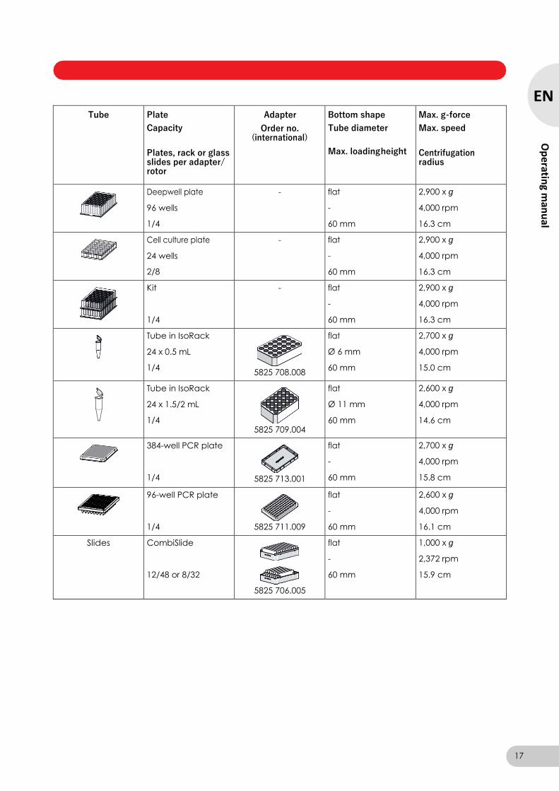
Deepwell plate
96 wells
1/4
- flat
-
60 mm
2,900 x g
4,000 rpm
16.3 cm
Cell culture plate
24 wells
2/8
- flat
-
60 mm
2,900 x g
4,000 rpm
16.3 cm
Kit
1/4
- flat
-
60 mm
2,900 x g
4,000 rpm
16.3 cm
Tube in IsoRack
24 x 0.5 mL
1/4
5825 708.008
flat
Ø 6 mm
60 mm
2,700 x g
4,000 rpm
15.0 cm
Tube in IsoRack
24 x 1.5/2 mL
1/4
5825 709.004
flat
Ø 11 mm
60 mm
2,600 x g
4,000 rpm
14.6 cm
384-well PCR plate
1/4
5825 713.001
flat
-
60 mm
2,700 x g
4,000 rpm
15.8 cm
96-well PCR plate
1/4
5825 711.009
flat
-
60 mm
2,600 x g
4,000 rpm
16.1 cm
Slides CombiSlide
12/48 or 8/32
5825 706.005
flat
-
60 mm
1,000 x g
2,372 rpm
15.9 cm
17
EN
Op
erating m
anu
al
Centrifuge 5804/5804 R/5810/5810 R — Operating manual
Tube Plate
Capacity
Plates, rack or glass slides per adapter/ rotor
Adapter
Order no. (international)
Bottom shape
Tube diameter
Max. loading height
Max. g-force
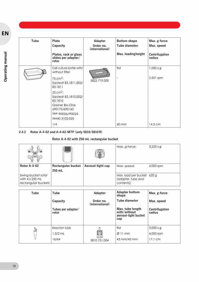
Max. speed
Centrifugation radius
Cell culture bottle with/
5825 719.000
flat 1,000 x g
without filter
75 cm2: - 2,501 rpm
Sarstedt 83.1811.002/
83.1811
25 cm2:
Sarstedt 83.1810.002/
83.1810
Greiner Bio-One
690175/690160
TPP 90026/90025
IWAKI 3102-025
1/4 60 mm 14.3 cm
2.4.2 Rotor A-4-62 and A-4-62-MTP (only 5810/5810 R)
Rotor A-4-62 with 250 mL rectangular bucket
Max. g-force: 3,220 x g
Rotor A-4-62 Rectangular bucket Aerosol-tight cap Max. speed: 4,000 rpm
250 mL
Swing-bucket rotor Max. load per bucket 620 g
with 4 x 250 mL (adapter, tube and
rectangular buckets contents):
Tube Tube
Capacity
Tubes per adapter/ rotor
Adapter
Order no. (international)
Adapter bottom shape
Tube diameter
Max. tube length with/without aerosol-tight bucket cap
Max. g-force
Max. speed
Centrifugation radius
Reaction tube
1.5/2 mL
16/64
5810 751.004
flat
Ø 11 mm
43 mm/43 mm
3,000 x g
4,000 rpm
17.1 cm
18
EN
Op
erat
ing
man
ual
Centrifuge 5804/5804 R/5810/5810 R — Operating manual
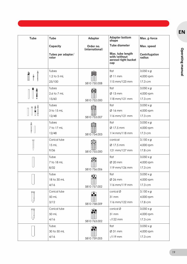
Tube Tube
Capacity
Tubes per adapter/ rotor
Adapter
Order no.
(international)
Adapter bottom shape
Tube diameter
Max. tube length with/without aerosol-tight bucket cap
Max. g-force
Max. speed
Centrifugation radius
Tubes
1.2 to 5 mL
25/100
5810 750.008
flat
Ø 11 mm
115 mm/123 mm
3,050 x g
4,000 rpm
17.3 cm
Tubes
2.6 to 7 mL
15/60
5810 752.000
flat
Ø 13 mm
118 mm/121 mm
3,050 x g
4,000 rpm
17.3 cm
Tubes
3 to 15 mL
12/48
5810 753.007
flat
Ø 16 mm
116 mm/121 mm
3,050 x g
4,000 rpm
17.3 cm
Tubes
7 to 17 mL
12/48
5810 754.003
flat
Ø 17.5 mm
114 mm/118 mm
3,050 x g
4,000 rpm
17.3 cm
Conical tube
15 mL
9/36
5810 755.000
conical
Ø 17.5 mm
121 mm/127 mm
3,150 x g
4,000 rpm
17.8 cm
Tube
7 to 18 mL
8/32
5810 756.006
flat
Ø 20 mm
119 mm/126 mm
3,050 x g
4,000 rpm
17.3 cm
Tube
18 to 30 mL
4/16
5810 757.002
flat
Ø 26 mm
116 mm/119 mm
3,050 x g
4,000 rpm
17.3 cm
Conical tube
50 mL
3/12
5810 758.009
conical Ø
31 mm
116 mm/122 mm
3,150 x g
4,000 rpm
17.8 cm
Conical tube
50 mL
4/16
5810 763.002
conical Ø
31 mm
-/122 mm
3,050 x g
4,000 rpm
17.3 cm
Tube
30 to 50 mL
4/16
5810 759.005
flat
Ø 31 mm
-/119 mm
3,050 x g
4,000 rpm
17.3 cm
19
EN
Op
erating m
anu
al

Centrifuge 5804/5804 R/5810/5810 R — Operating manual
Tube Tube
Capacity
Tubes per adapter/ rotor
Adapter
Order no.
(international)
Adapter bottom shape
Tube diameter
Max. tube length with/without aerosol-tight bucket cap
Max. g-force
Max. speed
Centrifugation radius
Conical tube, skirted
50 mL
flat
Ø 31 mm
3,050 x g
4,000 rpm
4/16 5810 759.005 -/119 mm 17.3 cm
5804 737.008
Tube
50 to 75 mL
2/8
5810 760.003
flat
Ø 35 mm
118/122 mm
3,050 x g
4,000 rpm
17.3 cm
Tube
80 to 120 mL
1/4
5810 761.000
flat
Ø 45 mm
125/138 mm
3,050 x g
4,000 rpm
17.3 cm
Bottles
180 to 250 mL
1/4
5810 770.009
flat
Ø 62 mm
127/136 mm
3,220 x g
4,000 rpm
18.0 cm
20
EN
Op
erat
ing
man
ual
Centrifuge 5804/5804 R/5810/5810 R — Operating manual
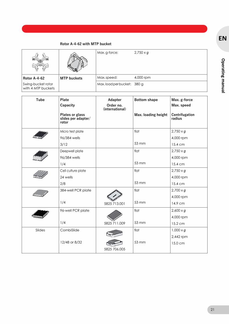
Rotor A-4-62 with MTP bucket
Max. g-force: 2,750 x g
Rotor A-4-62
Swing-bucket rotor
with 4 MTP buckets
MTP buckets Max. speed: 4,000 rpm
Max. load per bucket: 380 g
Tube Plate
Capacity
Plates or glass slides per adapter/ rotor
Adapter
Order no. (international)
Bottom shape
Max. loading height
Max. g-force
Max. speed
Centrifugation radius
Micro test plate
96/384 wells
3/12
flat
53 mm
2,750 x g
4,000 rpm
15.4 cm
Deepwell plate
96/384 wells
1/4
flat
53 mm
2,750 x g
4,000 rpm
15.4 cm
Cell culture plate
24 wells
2/8
flat
53 mm
2,750 x g
4,000 rpm
15.4 cm
384-well PCR plate
1/4
5825 713.001
flat
53 mm
2,700 x g
4,000 rpm
14.9 cm
96-well PCR plate
1/4
5825 711.009
flat
53 mm
2,600 x g
4,000 rpm
15.2 cm
Slides CombiSlide
12/48 or 8/32
5825 706.005
flat
53 mm
1,000 x g
2,442 rpm
15.0 cm
21
EN
Op
erating m
anu
al

Centrifuge 5804/5804 R/5810/5810 R — Operating manual
2.4.3 Rotor A-4-44
Max. g-force: 4,400 x g
Rotor A-4-44 Rectangular bucket Aerosol-tight cap Max. speed: 5,000 rpm
100 mL
Swing-bucket rotor Max. load per bucket 310 g
with 4 x 100 mL (adapter, tube and
rectangular buckets contents):
Tube Tube
Capacity
Tubes per adapter/ rotor
Adapter
Order no. (international)
Adapter bottom shape
Tube diameter
Max. tube length with/without aerosol-tight bucket cap
Max. g-force
Max. speed
Centrifugation radius
Reaction tube
1.5/2 mL
12/48
5804 751.000
flat
Ø 11 mm
43 mm/43 mm
4,100 x g
5,000 rpm
14.8 cm
Tubes
1.2 to 5 mL
14/56
5804 750.004
flat
Ø 11 mm
102 mm/105 mm
4,200 x g
5,000 rpm
15.0 cm
Tubes
2.6 to 7 mL
9/36
5804 752.007
flat
Ø 13 mm
106 mm/108 mm
4,200 x g
5,000 rpm
15.0 cm
Tubes
3 to 15 mL
7/28
5804 753.003
flat
Ø 16 mm
106 mm/108 mm
4,200 x g
5,000 rpm
15.0 cm
Tubes
7 to 17 mL
6/24
5804 754.000
flat
Ø 17.5 mm
106 mm/110 mm
4,200 x g
5,000 rpm
15.0 cm
Conical tube
15 mL
4/16
5804 755.006
conical
Ø 17.5 mm
-/121 mm
4,300 x g
5,000 rpm
15.5 cm
Conical tube
15 mL
2/8
5804 717.007
conical
Ø 17.5 mm
121 mm/121 mm
4,400 x g
5,000 rpm
15.7 cm
22
EN
Op
erat
ing
man
ual
Centrifuge 5804/5804 R/5810/5810 R — Operating manual
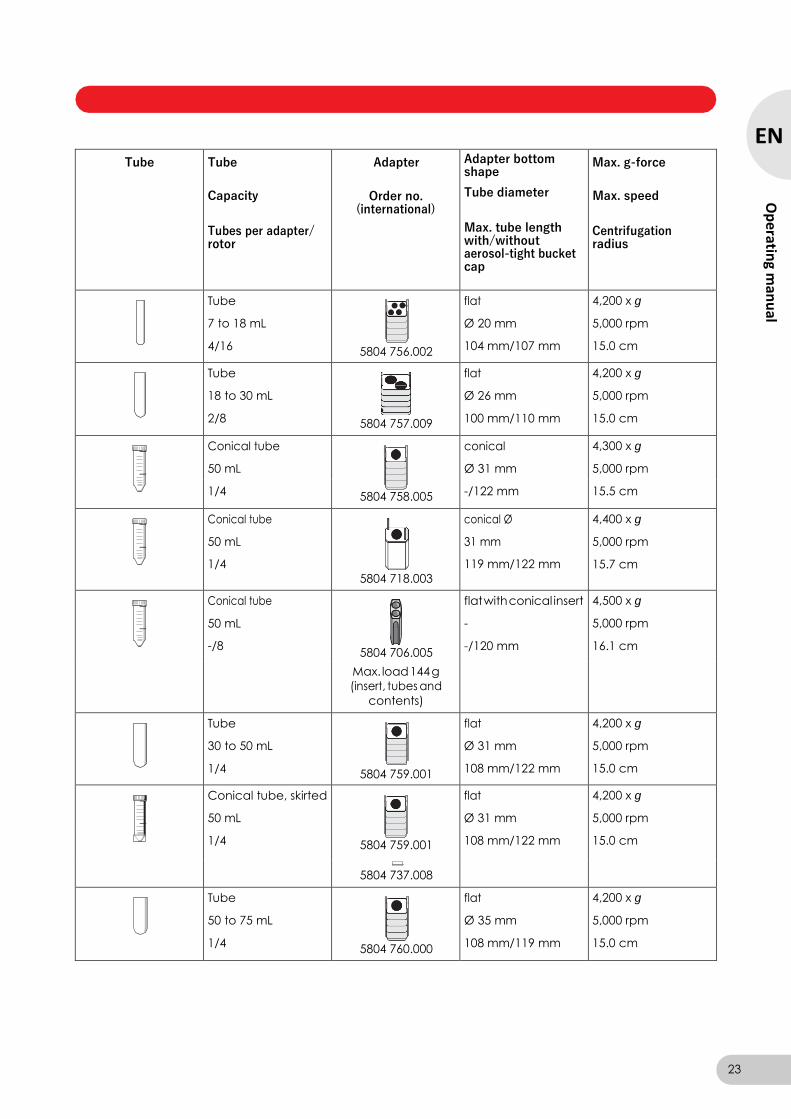
Tube Tube
Capacity
Tubes per adapter/ rotor
Adapter
Order no.
(international)
Adapter bottom shape
Tube diameter
Max. tube length with/without aerosol-tight bucket cap
Max. g-force
Max. speed
Centrifugation radius
Tube
7 to 18 mL
4/16
5804 756.002
flat
Ø 20 mm
104 mm/107 mm
4,200 x g
5,000 rpm
15.0 cm
Tube
18 to 30 mL
2/8
5804 757.009
flat
Ø 26 mm
100 mm/110 mm
4,200 x g
5,000 rpm
15.0 cm
Conical tube
50 mL
conical
Ø 31 mm
4,300 x g
5,000 rpm
1/4 5804 758.005 -/122 mm 15.5 cm
Conical tube
50 mL
1/4
5804 718.003
conical Ø
31 mm
119 mm/122 mm
4,400 x g
5,000 rpm
15.7 cm
Conical tube
50 mL
-/8
5804 706.005
flat with conical insert
-
-/120 mm
4,500 x g
5,000 rpm
16.1 cm
Max. load 144 g
(insert, tubes and
contents)
Tube
30 to 50 mL
1/4
5804 759.001
flat
Ø 31 mm
108 mm/122 mm
4,200 x g
5,000 rpm
15.0 cm
Conical tube, skirted
50 mL
flat
Ø 31 mm
4,200 x g
5,000 rpm
1/4 5804 759.001 108 mm/122 mm 15.0 cm
5804 737.008
Tube
50 to 75 mL
1/4
5804 760.000
flat
Ø 35 mm
108 mm/119 mm
4,200 x g
5,000 rpm
15.0 cm
23
EN
Op
erating m
anu
al
Centrifuge 5804/5804 R/5810/5810 R — Operating manual
Tube Tube
Capacity
Tubes per adapter/ rotor
Adapter
Order no.
(international)
Adapter bottom shape
Tube diameter
Max. tube length with/without aerosol-tight bucket cap
Max. g-force
Max. speed
Centrifugation radius
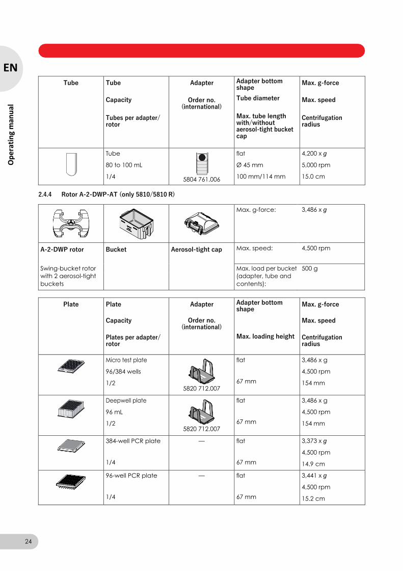
Tube
80 to 100 mL
1/4
5804 761.006
flat
Ø 45 mm
100 mm/114 mm
4,200 x g
5,000 rpm
15.0 cm
2.4.4 Rotor A-2-DWP-AT (only 5810/5810 R)
Max. g-force: 3,486 x g
A-2-DWP rotor Bucket Aerosol-tight cap Max. speed: 4,500 rpm
Swing-bucket rotor Max. load per bucket 500 g
with 2 aerosol-tight (adapter, tube and
buckets contents):
Plate Plate
Capacity
Plates per adapter/ rotor
Adapter
Order no. (international)
Adapter bottom shape
Max. loading height
Max. g-force
Max. speed
Centrifugation radius
Micro test plate
96/384 wells
1/2
5820 712.007
flat
67 mm
3,486 x g
4,500 rpm
154 mm
Deepwell plate
96 mL
1/2
5820 712.007
flat
67 mm
3,486 x g
4,500 rpm
154 mm
384-well PCR plate
1/4
— flat
67 mm
3,373 x g
4,500 rpm
14.9 cm
96-well PCR plate
1/4
— flat
67 mm
3,441 x g
4,500 rpm
15.2 cm
24
EN
Op
erat
ing
man
ual
Centrifuge 5804/5804 R/5810/5810 R — Operating manual
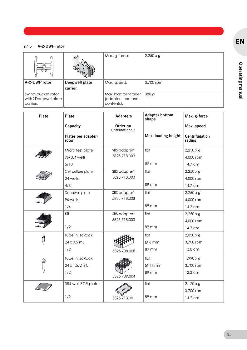
2.4.5 A-2-DWP rotor
Max. g-force: 2,250 x g
A-2-DWP rotor Deepwell plate Max. speed: 3,700 rpm
carrier
Swing-bucket rotor Max. load per carrier 380 g
with 2 Deepwell plate (adapter, tube and
carriers contents):
Plate Plate
Capacity
Plates per adapter/ rotor
Adapters
Order no. (International)
Adapter bottom shape
Max. loading height
Max. g-force
Max. speed
Centrifugation radius
Micro test plate
96/384 wells
5/10
SBS adapter*
5825 718.003
flat
89 mm
2,250 x g
4,000 rpm
14.7 cm
Cell culture plate
24 wells
4/8
SBS adapter*
5825 718.003
flat
89 mm
2,250 x g
4,000 rpm
14.7 cm
Deepwell plate
96 wells
1/4
SBS adapter*
5825 718.003
flat
89 mm
2,250 x g
4,000 rpm
14.7 cm
Kit
1/2
SBS adapter*
5825 718.003
flat
89 mm
2,250 x g
4,000 rpm
14.7 cm
Tube in IsoRack
24 x 0.5 mL
1/2
5825 708.008
flat
Ø 6 mm
89 mm
2,050 x g
3,700 rpm
13.8 cm
Tube in IsoRack
24 x 1.5/2 mL
1/2
5825 709.004
flat
Ø 11 mm
89 mm
1,990 x g
3,700 rpm
13.3 cm
384-well PCR plate
1/2
5825 713.001
flat
89 mm
2,170 x g
3,700 rpm
14.2 cm
25
EN
Op
erating m
anu
al
Centrifuge 5804/5804 R/5810/5810 R — Operating manual
Plate Plate
Capacity
Plates per adapter/ rotor
Adapters
Order no. (International)
Adapter bottom shape
Max. loading height
Max. g-force
Max. speed
Centrifugation radius
96-well PCR plate
1/2
5825 711.009
flat
89 mm
2,220 x g
3,700 rpm
14.5 cm
*) Optional. Secures the plate against slipping.
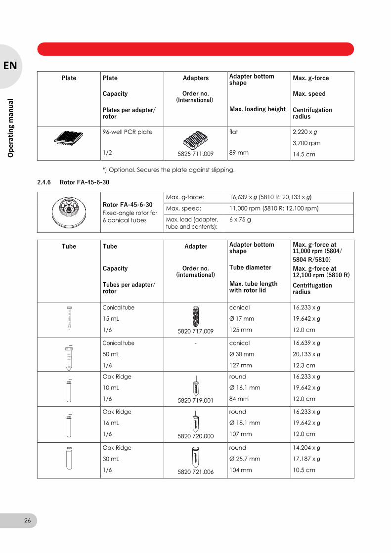
2.4.6 Rotor FA-45-6-30
Rotor FA-45-6-30
Fixed-angle rotor for
6 conical tubes
Max. g-force: 16,639 x g (5810 R: 20,133 x g)
Max. speed: 11,000 rpm (5810 R: 12,100 rpm)
Max. load (adapter,
tube and contents):
6 x 75 g
Tube Tube
Capacity
Tubes per adapter/ rotor
Adapter
Order no.
(international)
Adapter bottom shape
Tube diameter
Max. tube length with rotor lid
Max. g-force at 11,000 rpm (5804/
5804 R/5810)
Max. g-force at 12,100 rpm (5810 R)
Centrifugation radius
Conical tube
15 mL
1/6
5820 717.009
conical
Ø 17 mm
125 mm
16,233 x g
19,642 x g
12.0 cm
Conical tube
50 mL
1/6
- conical
Ø 30 mm
127 mm
16,639 x g
20,133 x g
12.3 cm
Oak Ridge
10 mL
1/6
5820 719.001
round
Ø 16.1 mm
84 mm
16,233 x g
19,642 x g
12.0 cm
Oak Ridge
16 mL
1/6
5820 720.000
round
Ø 18.1 mm
107 mm
16,233 x g
19,642 x g
12.0 cm
Oak Ridge
30 mL
1/6
5820 721.006
round
Ø 25.7 mm
104 mm
14,204 x g
17,187 x g
10.5 cm
26
EN
Op
erat
ing
man
ual
Centrifuge 5804/5804 R/5810/5810 R — Operating manual
Tube Tube
Capacity
Tubes per adapter/ rotor
Adapter
Order no.
(international)
Adapter bottom shape
Tube diameter
Max. tube length with rotor lid
Max. g-force at 11,000 rpm (5804/
5804 R/5810)
Max. g-force at 12,100 rpm (5810 R)
Centrifugation radius
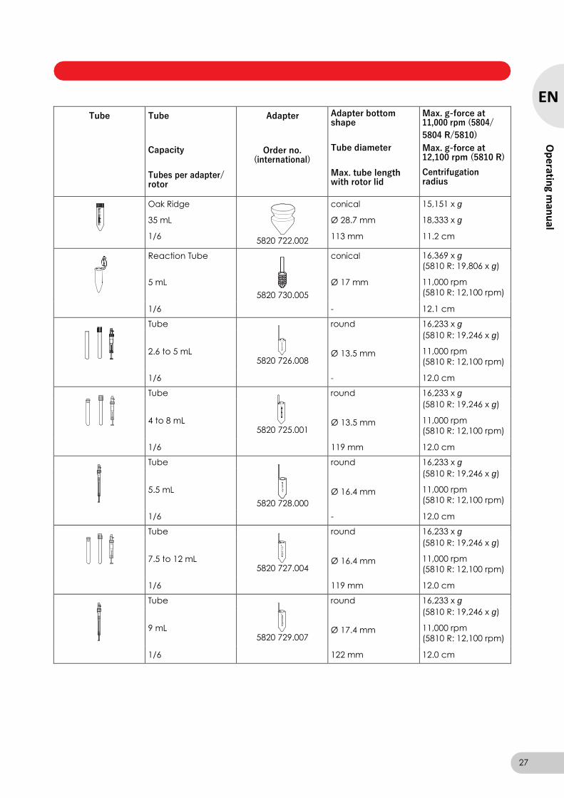
Oak Ridge
35 mL
1/6
5820 722.002
conical
Ø 28.7 mm
113 mm
15,151 x g
18,333 x g
11.2 cm
Reaction Tube
5 mL
5820 730.005
conical
Ø 17 mm
16,369 x g
(5810 R: 19,806 x g)
11,000 rpm
(5810 R: 12,100 rpm)
1/6 - 12.1 cm
Tube round 16,233 x g
2.6 to 5 mL
5820 726.008
Ø 13.5 mm
(5810 R: 19,246 x g)
11,000 rpm
(5810 R: 12,100 rpm)
1/6 - 12.0 cm
Tube round 16,233 x g
4 to 8 mL
5820 725.001
Ø 13.5 mm
(5810 R: 19,246 x g)
11,000 rpm
(5810 R: 12,100 rpm)
1/6 119 mm 12.0 cm
Tube round 16,233 x g
5.5 mL
5820 728.000
Ø 16.4 mm
(5810 R: 19,246 x g)
11,000 rpm
(5810 R: 12,100 rpm)
1/6 - 12.0 cm
Tube round 16,233 x g
7.5 to 12 mL
5820 727.004
Ø 16.4 mm
(5810 R: 19,246 x g)
11,000 rpm
(5810 R: 12,100 rpm)
1/6 119 mm 12.0 cm
Tube round 16,233 x g
9 mL
5820 729.007
Ø 17.4 mm
(5810 R: 19,246 x g)
11,000 rpm
(5810 R: 12,100 rpm)
1/6 122 mm 12.0 cm
27
EN
Op
erating m
anu
al

Centrifuge 5804/5804 R/5810/5810 R — Operating manual
2.4.7 Rotor F-34-6-38
28
EN
Op
erat
ing
man
ual
Rotor F-34-6-38
Fixed-angle rotor for
6 x 85 mL tubes
Max. g-force: 15,557 x g (5810 R: 18,514 x g)
Max. speed: 11,000 rpm (5810 R: 12,000 rpm)
Max. load (adapter,
tube and contents):
6 x 125 g
Tube Tube
Capacity
Tubes per adapter/ rotor
Adapter
Order no.
(international)
Adapter bottom shape
Tube diameter
Max. tube length with rotor lid
Max. g-force at 11,000 rpm (5804/
5804 R/5810)
Max. g-force at 12,100 rpm (5810 R)
Centrifugation radius
Reaction tube
1.5/2 mL
4/24
5804 770.005
round
Ø 11 mm
43 mm
15,300 x g
18,200 x g
11.3 cm
Blood collection tube
2 ml to 5 ml
3/18
5804 738.004
round
Ø13 mm
80 mm
14,339 x g
17,065 x g
10.6 cm
Blood collection tube
4 ml to 7 ml
3/18
5804 739.000
round
Ø13 mm
107 mm
15,442 x g
18,353 x g
11.4 cm
Tube
7 to 15 mL
2/12
5804 771.001
round
Ø 16 mm
112 mm
15,150 x g
18,000 x g
11.2 cm
Conical tube
15 mL
1/6
5804 776.003
conical
Ø 17.5 mm
123 mm
14,450 x g
17,200 x g
10.7 cm
Tube
15 to 18 mL
1/6
5804 772.008
round
Ø 18 mm
123 mm
14,750 x g
17,550 x g
10.9 cm
Tube
20 ml to 30 ml
1/6
5804 773.004
round
Ø26 mm
123 mm
14,900 x g
17,700 x g
11.0 cm
Tube
50 mL
1/6
5804 774.000
round
Ø 29 mm
123 mm
15,157 x g
18,014 x g
11.2 cm
Centrifuge 5804/5804 R/5810/5810 R — Operating manual
Tube Tube
Capacity
Tubes per adapter/ rotor
Adapter
Order no.
(international)
Adapter bottom shape
Tube diameter
Max. tube length with rotor lid
Max. g-force at 11,000 rpm (5804/
5804 R/5810)
Max. g-force at 12,100 rpm (5810 R)
Centrifugation radius
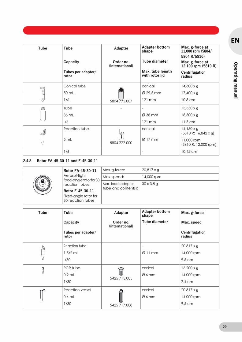
Conical tube conical 14,600 x g
50 mL Ø 29,5 mm 17,400 x g
1/6 5804 775.007 121 mm 10.8 cm
Tube
85 mL
-/6
- -
Ø 38 mm
121 mm
15,550 x g
18,500 x g
11.5 cm
Reaction tube
5 mL
5804 777.000
conical
Ø 17 mm
14,150 x g
(5810 R: 16,842 x g)
11,000 rpm
(5810 R: 12,000 rpm)
1/6 - 10.45 cm
2.4.8 Rotor FA-45-30-11 and F-45-30-11
Rotor FA-45-30-11
Aerosol-tight
fixed-angle rotor for 30
reaction tubes
Rotor F-45-30-11
Fixed-angle rotor for
30 reaction tubes
Max. g-force: 20,817 x g
Max. speed: 14,000 rpm
Max. load (adapter, 30 x 3.5 g
tube and contents):
Tube Tube
Capacity
Tubes per adapter/ rotor
Adapter
Order no. (international)
Adapter bottom shape
Tube diameter
Max. g-force
Max. speed
Centrifugation radius
Reaction tube
1.5/2 mL
-/30
- -
Ø 11 mm
20.817 x g
14,000 rpm
9.5 cm
PCR tube
0.2 mL
1/30
5425 715.005
conical
Ø 6 mm
16.200 x g
14,000 rpm
7.4 cm
Reaction vessel
0.4 mL
1/30
5425 717.008
conical
Ø 6 mm
20.817 x g
14,000 rpm
9.5 cm
29
EN
Op
erating m
anu
al
Centrifuge 5804/5804 R/5810/5810 R — Operating manual
Tube Tube
Capacity
Tubes per adapter/ rotor
Adapter
Order no. (international)
Adapter bottom shape
Tube diameter
Max. g-force
Max. speed
Centrifugation radius
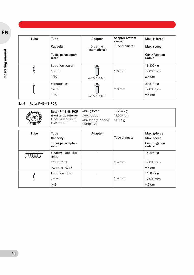
Reaction vessel
0.5 mL
1/30
5425 716.001
-
Ø 8 mm
18.400 x g
14,000 rpm
8.4 cm
Microtainers
0.6 mL
1/30
5425 716.001
-
Ø 8 mm
20,817 x g
14,000 rpm
9.5 cm
2.4.9 Rotor F-45-48-PCR
Rotor F-45-48-PCR
Fixed-angle rotor for
tube strips or 0.2 mL
PCR tubes
Max. g-force: 15,294 x g
Max. speed: 12,000 rpm
Max. load (tube and 6 x 3.5 g
contents):
Tube Tube
Capacity
Tubes per adapter/ rotor
Adapter
Tube diameter
Max. g-force
Max. speed
Centrifugation radius
8-tube/5-tube tube - 15,294 x g
strips
8/5 x 0.2 mL Ø 6 mm 12,000 rpm
-/6 x 8 or -/6 x 5 9.5 cm
Reaction tube
0.2 mL
-/48
-
Ø 6 mm
15,294 x g
12,000 rpm
9.5 cm
30
EN
Op
erat
ing
man
ual
Centrifuge 5804/5804 R/5810/5810 R — Operating manual
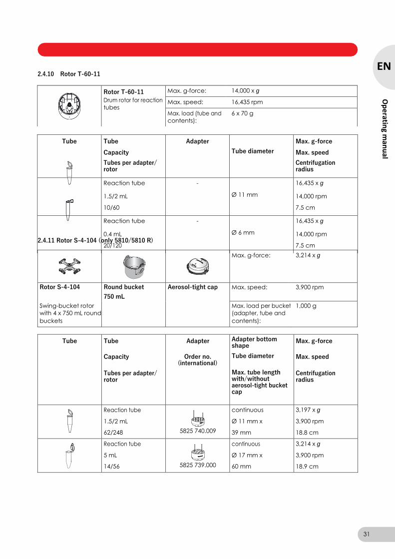
2.4.10 Rotor T-60-11
2.4.11 Rotor S-4-104 (only 5810/5810 R)
Max. g-force: 3,214 x g
Rotor S-4-104 Round bucket Aerosol-tight cap Max. speed: 3,900 rpm
750 mL
Swing-bucket rotor Max. load per bucket 1,000 g
with 4 x 750 mL round (adapter, tube and
buckets contents):
Tube Tube
Capacity
Tubes per adapter/ rotor
Adapter
Order no. (international)
Adapter bottom shape
Tube diameter
Max. tube length with/without aerosol-tight bucket cap
Max. g-force
Max. speed
Centrifugation radius
Reaction tube
1.5/2 mL
62/248
5825 740.009
continuous
Ø 11 mm x
39 mm
3,197 x g
3,900 rpm
18.8 cm
Reaction tube
5 mL
14/56
5825 739.000
continuous
Ø 17 mm x
60 mm
3,214 x g
3,900 rpm
18.9 cm
31
EN
Op
erating m
anu
al
Rotor T-60-11
Drum rotor for reaction
tubes
Max. g-force: 14,000 x g
Max. speed: 16,435 rpm
Max. load (tube and
contents):
6 x 70 g
Tube Tube
Capacity
Tubes per adapter/ rotor
Adapter
Tube diameter
Max. g-force
Max. speed
Centrifugation radius
Reaction tube
1.5/2 mL
10/60
-
Ø 11 mm
16,435 x g
14,000 rpm
7.5 cm
Reaction tube
0.4 mL
20/120
-
Ø 6 mm
16,435 x g
14,000 rpm
7.5 cm
Centrifuge 5804/5804 R/5810/5810 R — Operating manual
EN Tube Tube
Capacity
Tubes per adapter/ rotor
Adapter
Order no.
(international)
Adapter bottom shape
Tube diameter
Max. tube length with/without aerosol-tight bucket cap
Max. g-force
Max. speed
Centrifugation radius
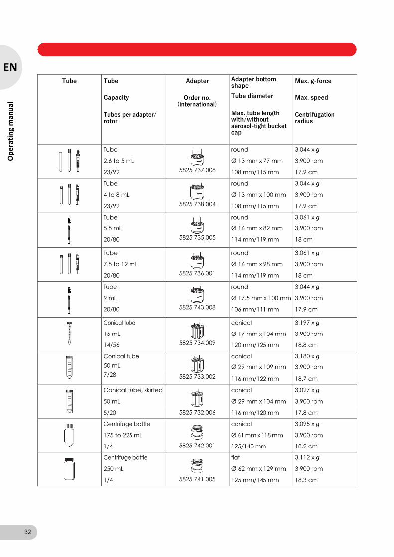
Tube
2.6 to 5 mL
23/92
5825 737.008
round
Ø 13 mm x 77 mm
108 mm/115 mm
3,044 x g
3,900 rpm
17.9 cm
Tube
4 to 8 mL
23/92
5825 738.004
round
Ø 13 mm x 100 mm
108 mm/115 mm
3,044 x g
3,900 rpm
17.9 cm
Tube
5.5 mL
20/80
5825 735.005
round
Ø 16 mm x 82 mm
114 mm/119 mm
3,061 x g
3,900 rpm
18 cm
Tube
7.5 to 12 mL
20/80
5825 736.001
round
Ø 16 mm x 98 mm
114 mm/119 mm
3,061 x g
3,900 rpm
18 cm
Tube
9 mL
20/80
5825 743.008
round
Ø 17.5 mm x 100 mm
106 mm/111 mm
3,044 x g
3,900 rpm
17.9 cm
Conical tube
15 mL
14/56
5825 734.009
conical
Ø 17 mm x 104 mm
120 mm/125 mm
3,197 x g
3,900 rpm
18.8 cm
Conical tube
50 mL
conical
Ø 29 mm x 109 mm
3,180 x g
3,900 rpm
7/28 5825 733.002 116 mm/122 mm 18.7 cm
Conical tube, skirted
50 mL
conical
Ø 29 mm x 104 mm
3,027 x g
3,900 rpm
5/20 5825 732.006 116 mm/120 mm 17.8 cm
Centrifuge bottle
175 to 225 mL
1/4
5825 742.001
conical
Ø 61 mm x 118 mm
125/143 mm
3,095 x g
3,900 rpm
18.2 cm
Centrifuge bottle
250 mL
1/4
5825 741.005
flat
Ø 62 mm x 129 mm
125 mm/145 mm
3,112 x g
3,900 rpm
18.3 cm
32
Op
erat
ing
man
ual

Centrifuge 5804/5804 R/5810/5810 R — Operating manual
Tube Tube
Capacity
Tubes per adapter/ rotor
Adapter
Order no.
(international)
Adapter bottom shape
Tube diameter
Max. tube length with/without aerosol-tight bucket cap
Max. g-force
Max. speed
Centrifugation radius
Wide-neck bottle
750 mL
1/4
5825 744.004
flat
Ø 102 mm x 132 mm
132 mm/150 mm
3,146 x g
3,900 rpm
18.5 cm
2.4.12 Rotor S-4-72
Max. g-force: 3,234 x g
Rotor S-4-72
Swing-bucket rotor with 4 x 250 mL round
buckets
Round bucket 250 mL
Max. speed: 4,200 rpm
Max. load per bucket 450 g
(adapter, tube and
contents):
Tube Tube
Capacity
Tubes per adapter/ rotor
Adapter
Order no. (international)
Adapter bottom shape
Tube diameter
Max. tube length
Max. g-force
Max. speed
Centrifugation radius
Reaction tube
1.5/2 mL
26/104
5804 794.001
continuous
Ø 11 mm
43 mm
3,136 x g
4,200 rpm
15.9 cm
Reaction tube
5 mL
5804 793.005
conical
Ø 17 mm x
60 mm
3,215 x g
4,200 rpm
16.3 cm
Tube
2.6 to 5 mL
14/56
5804 788.001
round
Ø 13 mm x 77 mm
115 mm
3,136 x g
4,200 rpm
15.9 cm
Tube
4 to 8 mL
14/56
5804 789.008
round
Ø 13 mm x 104 mm
115 mm
3,136 x g
4,200 rpm
15.9 cm
Tube
5.5 mL
13/52
5804 790.006
round
Ø 16 mm x 82 mm
112 mm
3,096 x g
4,200 rpm
15.7 cm
33
EN
Op
erating m
anu
al
Centrifuge 5804/5804 R/5810/5810 R — Operating manual
EN Tube Tube
Capacity
Tubes per adapter/ rotor
Adapter
Order no.
(international)
Adapter bottom shape
Tube diameter
Max. tube length
Max. g-force
Max. speed
Centrifugation radius
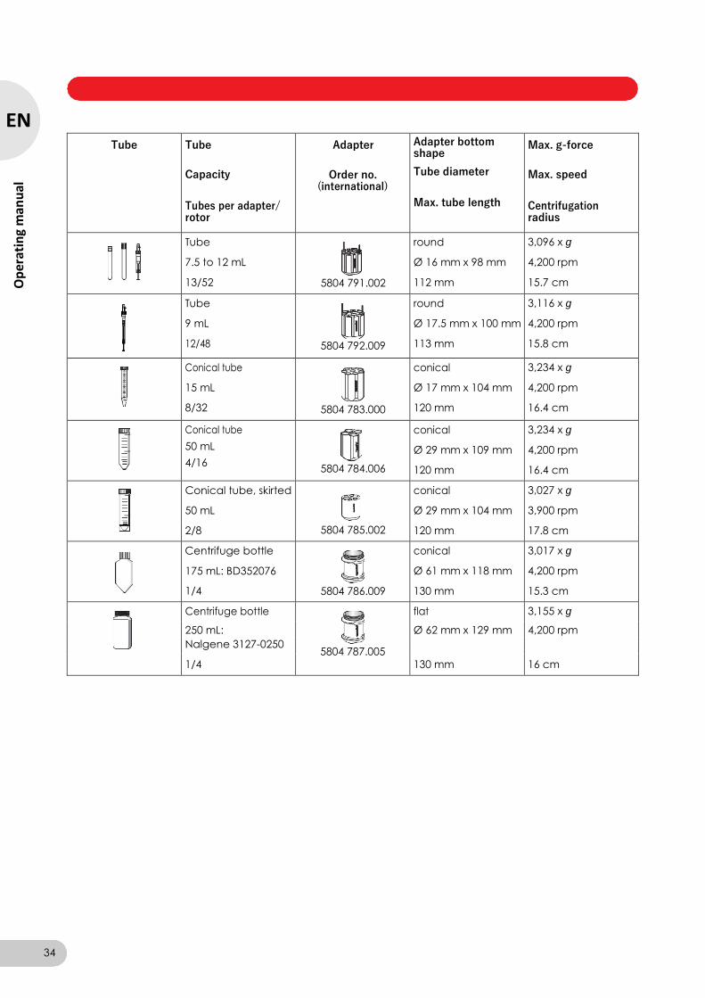
Tube
7.5 to 12 mL
13/52
5804 791.002
round
Ø 16 mm x 98 mm
112 mm
3,096 x g
4,200 rpm
15.7 cm
Tube
9 mL
12/48
5804 792.009
round
Ø 17.5 mm x 100 mm
113 mm
3,116 x g
4,200 rpm
15.8 cm
Conical tube
15 mL
8/32
5804 783.000
conical
Ø 17 mm x 104 mm
120 mm
3,234 x g
4,200 rpm
16.4 cm
Conical tube
50 mL
4/16
5804 784.006
conical
Ø 29 mm x 109 mm
120 mm
3,234 x g
4,200 rpm
16.4 cm
Conical tube, skirted
50 mL
conical
Ø 29 mm x 104 mm
3,027 x g
3,900 rpm
2/8 5804 785.002 120 mm 17.8 cm
Centrifuge bottle
175 mL: BD352076
1/4
5804 786.009
conical
Ø 61 mm x 118 mm
130 mm
3,017 x g
4,200 rpm
15.3 cm
Centrifuge bottle
5804 787.005
flat 3,155 x g
250 mL: Ø 62 mm x 129 mm 4,200 rpm
Nalgene 3127-0250
1/4 130 mm 16 cm
34
Op
erat
ing
man
ual
Centrifuge 5804/5804 R/5810/5810 R — Operating manual
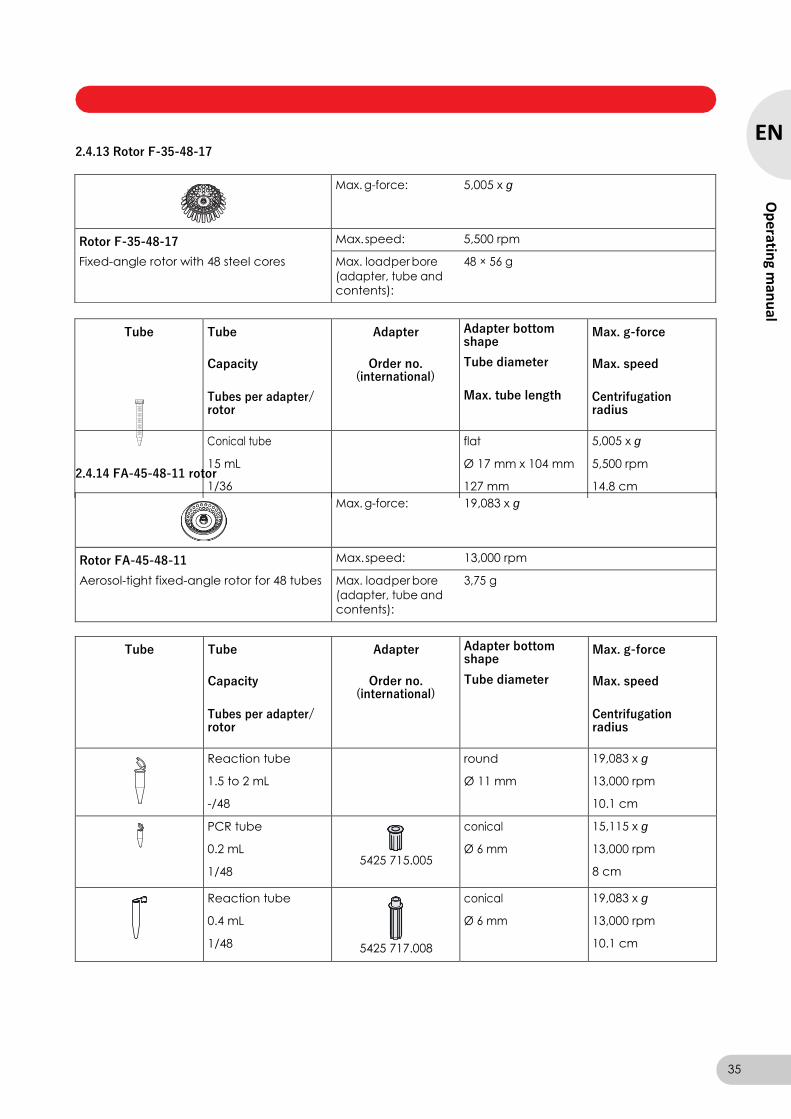
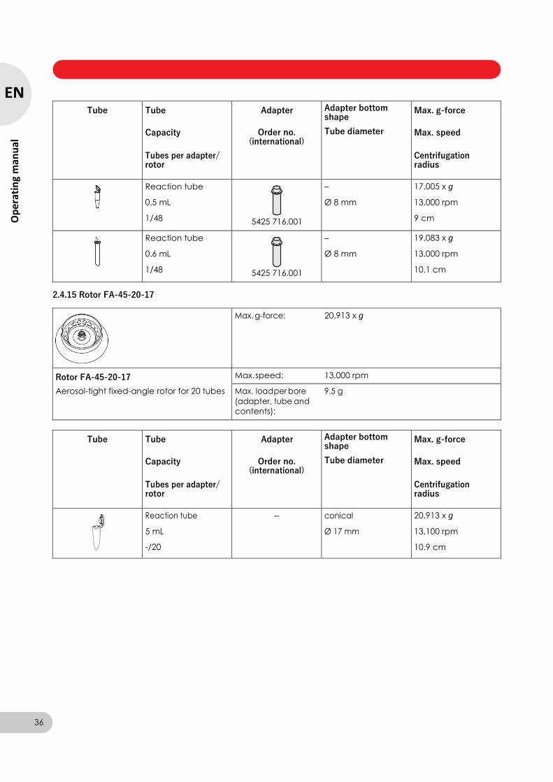
2.4.13 Rotor F-35-48-17
2.4.14 FA-45-48-11 rotor
Max. g-force: 19,083 x g
Rotor FA-45-48-11
Aerosol-tight fixed-angle rotor for 48 tubes
Max. speed: 13,000 rpm
Max. load per bore 3,75 g
(adapter, tube and
contents):
Tube Tube
Capacity
Tubes per adapter/ rotor
Adapter
Order no. (international)
Adapter bottom shape
Tube diameter
Max. g-force
Max. speed
Centrifugation radius
Reaction tube
1.5 to 2 mL
-/48
round
Ø 11 mm
19,083 x g
13,000 rpm
10.1 cm
PCR tube
0.2 mL
1/48
5425 715.005
conical
Ø 6 mm
15,115 x g
13,000 rpm
8 cm
Reaction tube
0.4 mL
1/48
5425 717.008
conical
Ø 6 mm
19,083 x g
13,000 rpm
10.1 cm
35
EN
Op
erating m
anu
al
Max. g-force: 5,005 x g
Rotor F-35-48-17
Fixed-angle rotor with 48 steel cores
Max. speed: 5,500 rpm
Max. load per bore 48 × 56 g
(adapter, tube and contents):
Tube Tube
Capacity
Tubes per adapter/ rotor
Adapter
Order no. (international)
Adapter bottom shape
Tube diameter
Max. tube length
Max. g-force
Max. speed
Centrifugation radius
Conical tube
15 mL
1/36
flat
Ø 17 mm x 104 mm
127 mm
5,005 x g
5,500 rpm
14.8 cm
Centrifuge 5804/5804 R/5810/5810 R — Operating manual
Tube Tube
Capacity
Tubes per adapter/ rotor
Adapter
Order no. (international)
Adapter bottom shape
Tube diameter
Max. g-force
Max. speed
Centrifugation radius
Reaction tube
0.5 mL
1/48
5425 716.001
–
Ø 8 mm
17,005 x g
13,000 rpm
9 cm
Reaction tube
0.6 mL
1/48
5425 716.001
–
Ø 8 mm
19,083 x g
13,000 rpm
10.1 cm
2.4.15 Rotor FA-45-20-17
Max. g-force: 20,913 x g
Rotor FA-45-20-17
Aerosol-tight fixed-angle rotor for 20 tubes
Max. speed: 13,000 rpm
Max. load per bore 9.5 g
(adapter, tube and
contents):
Tube Tube
Capacity
Tubes per adapter/ rotor
Adapter
Order no. (international)
Adapter bottom shape
Tube diameter
Max. g-force
Max. speed
Centrifugation radius
Reaction tube
5 mL
-/20
– conical
Ø 17 mm
20,913 x g
13,100 rpm
10.9 cm
36
EN
Op
erat
ing
man
ual
Centrifuge 5804/5804 R/5810/5810 R — Operating manual
3.1 Intended use
3.2 User profile
The 5804/5804 R/5810/5810 R centrifuge is intended exclusively for indoor use and for
separating aqueous solutions and suspensions of various densities in approved test tubes.
This device may only be operated by trained specialist staff. They must have carefully read the
operating manual and be familiar with the function of the device.
3.3 Application limits
3.3.1 Declaration concerning the ATEX directive (94/9/EC)
DANGER!
Risk of explosion.
Do not operate the device in areas where work is completed with explosive substances.
Do not use this device to process any explosive or highly reactive substances.
Do not use this device to process any substances which could create an explosive
atmosphere.
The 5804/5804 R/5810/5810 R centrifuge is not suitable for use in a potentially explosive
atmosphere due to its design and the ambient conditions inside the device.
The device only must be used in a safe environment, such as in the open environment of a
ventilated laboratory or fume hood. The use of substances that may contribute to a potentially
explosive atmosphere is not permitted. The user is responsible for making the final decision
regarding the risks associated with the use of such substances.
3.3.2 Maximum service life for accessories
CAUTION!
Risk of injury from chemically or mechanically damaged accessories.
Even minor scratches and cracks can result in serious damage to the accessories.
Protect all accessory parts from damage.
Inspect the accessories for damage before each use. Replace any damaged accessories.
Do not use rotors, rotor lids, carriers, buckets or caps with signs of corrosion or mechanical
damage (e.g. deformations).
Do not use accessories whose maximum service life has been exceeded.
When inserting the buckets and rotors, ensure that they do not become scratched.
CAUTION!
Risk of injury due to chemically damaged rotor lids resp. caps.
Transparent rotor lids resp. caps out of PC, PP or PEI may lose their strength under the impact of
organic solvents (e.g. phenol, chloroform).
Regularly check the rotor lids resp. caps for damages and cracks.
Immediately replace any rotor lids resp. caps showing cracks or milky stains.
3 Safety
37
EN
Op
erating m
anu
al
Centrifuge 5804/5804 R/5810/5810 R — Operating manual
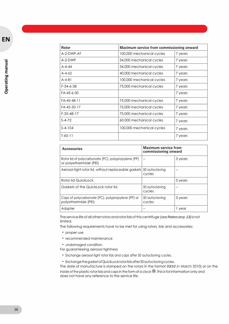
Rotor Maximum service from commissioning onward
A-2-DWP-AT 100,000 mechanical cycles 7 years
A-2-DWP 34,000 mechanical cycles 7 years
A-4-44 34,000 mechanical cycles 7 years
A-4-62 40,000 mechanical cycles 7 years
A-4-81 100,000 mechanical cycles 7 years
F-34-6-38 75,000 mechanical cycles 7 years
FA-45-6-30 7 years
FA-45-48-11 75,000 mechanical cycles 7 years
FA-45-20-17 75,000 mechanical cycles 7 years
F-35-48-17 75,000 mechanical cycles 7 years
S-4-72 60,000 mechanical cycles 7 years
S-4-104 100,000 mechanical cycles 7 years
T-60-11 7 years
Accessories Maximum service from commissioning onward
Rotor lid of polycarbonate (PC), polypropylene (PP)
or polyetherimide (PEI)
-- 3 years
Aerosol-tight rotor lid, without replaceable gaskets 50 autoclaving
cycles
--
Rotor lid QuickLock 3 years
Gaskets of the QuickLock rotor lid 50 autoclaving
cycles
--
Caps of polycarbonate (PC), polypropylene (PP) or
polyetherimide (PEI)
50 autoclaving
cycles
3 years
Adapter -- 1 year
The service life of all other rotors and rotor lids of this centrifuge (see Rotors on p. 13) is not
limited.
The following requirements have to be met for using rotors, lids and accessories:
• proper use
• recommended maintenance
• undamaged condition.
For guaranteeing aerosol tightness
• Exchange aerosol-tight rotor lids and caps after 50 autoclaving cycles.
• Exchange the gasket of QuickLock rotor lids after 50 autoclaving cycles.
The date of manufacture is stamped on the rotors in the format 03/10 (= March 2010) or on the
inside of the plastic rotor lids and caps in the form of a clock . This is for information only and
does not have any reference to the service life.
38
EN
Op
erat
ing
man
ual

Centrifuge 5804/5804 R/5810/5810 R — Operating manual
3.4 Information on product liability
In the following cases, the designated protection of the device may be compromised. Liability for
any resulting property damage or personal injury is then transferred to the operator:
• The device is not used in accordance with the operating manual.
• The device is used outside of its intended use.
• The device is used with accessories or consumables which are not recommended by Eppendorf.
• The device is maintained or repaired by people not authorized by Eppendorf.
• The user makes unauthorized changes to the device.
3.5 Warnings for intended use
Before using 5804/5804 R/5810/5810 R centrifuge first read the operating manual and observe
the following general safety instructions.
3.5.1 Personal injury or damage to the equipment
WARNING!
Electric shock due to damage to device or mains cable.
Only switch on the device if the device and mains cable are undamaged.
Only use devices that have been properly installed or repaired.
In case of danger, disconnect the device from the mains supply.
WARNING!
Lethal voltages inside the device.
Ensure that the housing is always closed and undamaged so that no parts inside the device
can be contacted by accident.
Do not remove the housing of the device.
Do not allow any liquids to penetrate the inside of the housing.
Do not allow the device to be opened by anyone except service personnel who have been
specifically authorized by Eppendorf.
WARNING!
Risk from incorrect supply voltage
Only connect the device to power supplies which correspond with the electrical requirements
on the nameplate.
Only use sockets with a protective earth (PE) conductor and suitable power cable.
WARNING!
Damage to health due to handling infectious liquids and pathogenic germs.
When handling infectious liquids and pathogenic germs, observe the national regulations, the
biological security level of your laboratory, the material safety data sheets, and the
manufacturer's application notes.
For the centrifugation of these substances, use suitable aerosol-tight closure systems.
When working with pathogenic germs belonging to a higher risk group, more than one
aerosol-tight bioseal must be used.
Wear personal protective equipment.
Follow the instructions regarding hygiene, cleaning and decontamination.
For complete instructions regarding the handling of germs or biological material in risk group
II or higher, please refer to the "Laboratory Biosafety Manual" (Source: World Health
Organization, current edition of the Laboratory Biosafety Manual).
39
EN
Op
erating m
anu
al
Centrifuge 5804/5804 R/5810/5810 R — Operating manual
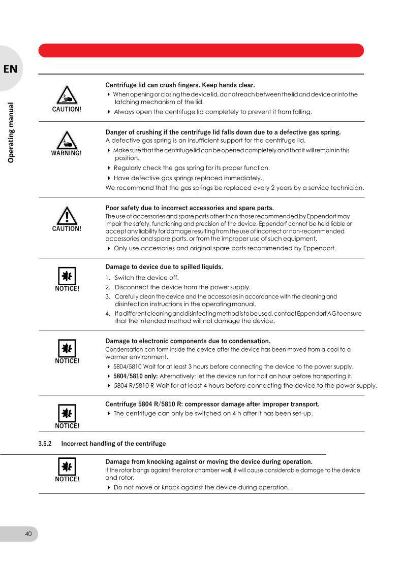
Centrifuge lid can crush fingers. Keep hands clear.
When opening or closing the device lid, do not reach between the lid and device or into the
latching mechanism of the lid.
CAUTION! Always open the centrifuge lid completely to prevent it from falling.
WARNING!
Danger of crushing if the centrifuge lid falls down due to a defective gas spring.
A defective gas spring is an insufficient support for the centrifuge lid.
Make sure that the centrifuge lid can be opened completely and that it will remain in this
position.
Regularly check the gas spring for its proper function.
Have defective gas springs replaced immediately.
We recommend that the gas springs be replaced every 2 years by a service technician.
CAUTION!
Poor safety due to incorrect accessories and spare parts.
The use of accessories and spare parts other than those recommended by Eppendorf may
impair the safety, functioning and precision of the device. Eppendorf cannot be held liable or
accept any liability for damage resulting from the use of incorrect or non-recommended
accessories and spare parts, or from the improper use of such equipment.
Only use accessories and original spare parts recommended by Eppendorf.
NOTICE!
Damage to device due to spilled liquids.
1. Switch the device off.
2. Disconnect the device from the power supply.
3. Carefully clean the device and the accessories in accordance with the cleaning and
disinfection instructions in the operating manual.
4. If a different cleaning and disinfecting method is to be used, contact Eppendorf AG to ensure
that the intended method will not damage the device.
NOTICE!
Damage to electronic components due to condensation.
Condensation can form inside the device after the device has been moved from a cool to a
warmer environment.
5804/5810 Wait for at least 3 hours before connecting the device to the power supply.
5804/5810 only: Alternatively: let the device run for half an hour before transporting it.
5804 R/5810 R Wait for at least 4 hours before connecting the device to the power supply.
NOTICE!
Centrifuge 5804 R/5810 R: compressor damage after improper transport.
The centrifuge can only be switched on 4 h after it has been set-up.
3.5.2 Incorrect handling of the centrifuge
NOTICE!
Damage from knocking against or moving the device during operation.
If the rotor bangs against the rotor chamber wall, it will cause considerable damage to the device
and rotor.
Do not move or knock against the device during operation.
40
EN
Op
erat
ing
man
ual
Centrifuge 5804/5804 R/5810/5810 R — Operating manual
3.5.3 Incorrect handling of the rotors
CAUTION!
Risk of injury from improperly attached rotors and rotor lids.
Only centrifuge when the rotor and rotor lid are firmly tightened.
If unusual noises occur when the centrifuge starts, the rotor or the rotor lid may not be properly secured. Stop centrifugation immediately by pressing the start/stop key.
CAUTION!
Risk of injury from asymmetric loading of rotors.
Load rotors symmetrically with identical tubes and/or buckets and plates.
Only load adapters with the suitable tubes and plates.
Always use the same type of tubes and plates (weight, material/density and volume).
Check for symmetric loading by using scales to balance the adapters and tubes or plates.
CAUTION!
Risk of injury from overloaded rotor.
The centrifuges are designed for the centrifugation of material with a max. density of 1.2 g/mL at
maximum speed and with maximum filling volume resp. load.
Observe the information on each rotor relating to maximum load (adapter, tube and contents)
per rotor bore/per bucket and make sure it is not exceeded.
NOTICE!
Damage to rotors from aggressive chemicals.
Rotors are high-quality components which withstand extreme stresses. This stability can be
impaired by aggressive chemicals.
Avoid the use of aggressive chemicals, including strong and weak alkalis, strong acids,
solutions with mercury, copper and other heavy metal ions, halogenated hydrocarbons,
concentrated saline solutions and phenol.
If the rotor is contaminated with aggressive chemicals, immediately clean it using a neutral
cleaning agent and then rinse it thoroughly with water. This applies to the rotor bores in
particular.
Due to the manufacturing process, color variations may occur on rotors marked "coated".
These color variations do not effect service life or resistance to chemicals.
NOTICE!
If handled incorrectly, the swing-bucket rotor can fall over.
Buckets from swing-bucket rotors may not be used as handles.
Before moving the rotor, remove the buckets.
Always pick up the rotor at the rotor cross using both hands.
NOTICE!
If handled incorrectly, the rotor can fall over.
Always pick up the rotor F-35-48-17 with both hands.
In order to hold the rotor safely, possibly you have to remove 3 to 4 sleeves from the opposite
outer row.
41
EN
Op
erating m
anu
al
Centrifuge 5804/5804 R/5810/5810 R — Operating manual
3.5.4 Extreme strain on the centrifuging tubes
CAUTION!
Risk of injury from overloaded tubes.
Note the loading limits specified by the tube manufacturer.
Only use tubes which are approved by the manufacturer for the specified g-forces (rcf).
NOTICE!
Risk from damaged tubes.
Damaged tubes must not be used, as this could lead to sample loss and further damage to the
device and accessories.
Visually check all tubes for damage before use.
NOTICE!
Risk from open tube lids.
Open tube lids can break off during centrifugation and cause damage to the rotor and the
centrifuge.
Carefully close all tube lids before centrifuging.
NOTICE!
Hazard to plastic tubes from organic solvents.
The use of organic solvents (e.g., phenol, chloroform) will reduce the strength of plastic tubes,
which could lead to tube damage.
Follow the manufacturer's information on the chemical resistance of tubes.
NOTICE!
Sample tubes heat up.
In non-cooled centrifuges, the temperature in the rotor chamber, rotor and sample may exceed
40 °C based on the run time, g-force (rcf)/speed (rpm) and ambient temperature.
Note that this can reduce the centrifugation resistance of the sample tubes.
Please note the temperature resistance of the samples.
3.5.5 Aerosol-tight centrifugation
WARNUNG!
Risk to health due to limited aersosol tightness in the event of incorrect use.
Autoclaving, mechanical stresses and contamination by chemicals or other aggressive solvents
can impair the aerosol-tightness of the rotors and rotor lid.
Regularly check that the seals of aerosol-tight rotor lids are undamaged.
Only use aerosol-tight rotor lids with undamaged and clean gaskets./Paragraph
Thinly brush the threads of the rotor lid screw after every proper autoclaving (121 °C, 20 min.)
with pivot grease (order no. Int.: 5810 350.050 / North America: 022634330). Do not apply the
pivot grease to the gaskets. Replace aerosol-tight rotor lids after 10 autoclave cycles.
Aerosol-tight rotors should never be stored with rotor lids screwed on tightly.
42
EN
Op
erat
ing
man
ual
Centrifuge 5804/5804 R/5810/5810 R — Operating manual
WARNING!
Risk to health due to limited aerosol tightness with incorrect rotor/rotor lid combination.
Aerosol-tight centrifugation is guaranteed only if the rotors and rotor lids intended for this purpose are used. For fixed-angle rotors the labeling always begins with FA, swing-bucket rotors are
labeled with AT (aerosol tight).
The aerosol-tight rotors and rotor lids are additionally marked with a red ring on the rotor and a
red rotor lid screw.
For aerosol-tight centrifugation, always simultaneously use rotors and rotor lids which are
marked as aerosol-tight in the centrifuge intended for the corresponding purpose. The details
specifying in which centrifuge you may use the aerosol-tight rotors and rotor lids can be found
on the rotor and, beginning from production date of October 2003, on the upper side of the
rotor lid.
Only use aerosol-tight rotor lids in combination with rotors which are marked on the rotor lid.
Only use aerosol-tight rotors/buckets with the corresponding rotor lids/caps.
3.6 Safety instructions on the device
Depiction Meaning Location
WARNING
General hazard point. Follow the operating manual.
Right side of the device
43
EN
Op
erating m
anu
al
Centrifuge 5804/5804 R/5810/5810 R — Operating manual
4 Installation
4.1 Selecting the location
NOTICE!
Damage to objects near the device.
If the rotor becomes damaged or an imbalance occurs, the device may change position slightly.
During operation, maintain a safe distance of 30 cm on all sides of the device in accordance with EN 61010-2-020.
NOTICE!
Damage from overheating.
Do not place the device near sources of heat (e.g., heater, drier compartment).
Do not expose the device to direct sunlight.
Ensure unobstructed air circulation. Ensure a minimum distance of 30 cm between all sides of
the devices and any adjacent devices or the wall. Make sure that the base of the device is not
obstructed.
Make sure that the air slots in the device are always free from obstructions.
NOTICE!
Radio interference.
This device is a category A product in accordance with EN 55011. There may be disturbance to
radio reception in residential areas.
Ensure that appropriate preventive measures are taken.
Select the location for the device according to the following criteria:
• Suitable power connection as per the name plate (230 V/120 V/100 V).
• Stable, horizontal and resonance-free lab bench. Weight of the device: 55 kg (5804) or 80 kg (5804 R), 68 kg (5810), 99 kg (5810 R).
• A well ventilated environment which is protected from direct sunlight to prevent the device from heating up more.
4.2 Preparing installation
CAUTION!
Bodily injury due to lifting and carrying heavy loads
The device is heavy. Lifting and carrying the device can lead to back injuries.
Transport the device without the rotor inserted.
The device may only be transported in its original packaging.
The device must be transported by least two people.
Use a transport aid (e.g., dolly) to transport the device longer distances.
Perform the following steps in the sequence described.
1. Open the box.
2. Remove the covering cardboard.
3. Remove the accessories.
44
EN
Op
erat
ing
man
ual
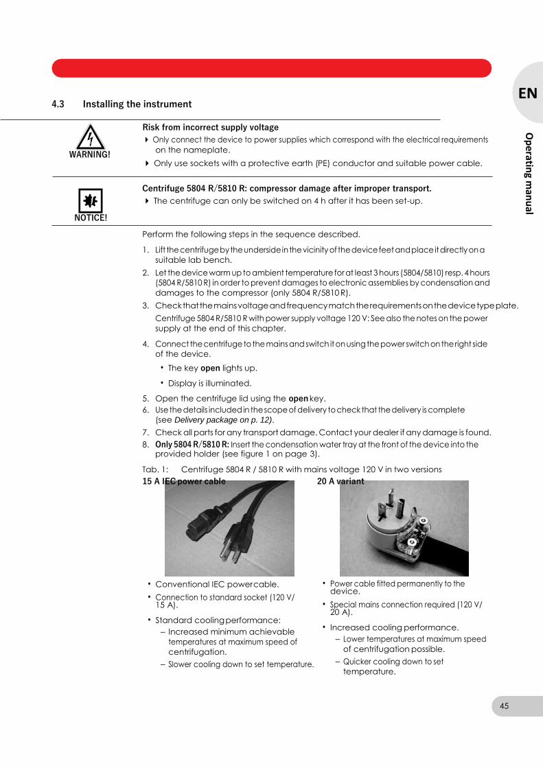
Centrifuge 5804/5804 R/5810/5810 R — Operating manual
4.3 Installing the instrument
WARNING!
Risk from incorrect supply voltage
Only connect the device to power supplies which correspond with the electrical requirements
on the nameplate.
Only use sockets with a protective earth (PE) conductor and suitable power cable.
NOTICE!
Centrifuge 5804 R/5810 R: compressor damage after improper transport.
The centrifuge can only be switched on 4 h after it has been set-up.
Perform the following steps in the sequence described.
1. Lift the centrifuge by the underside in the vicinity of the device feet and place it directly on a
suitable lab bench.
2. Let the device warm up to ambient temperature for at least 3 hours (5804/5810) resp. 4 hours
(5804 R/5810 R) in order to prevent damages to electronic assemblies by condensation and
damages to the compressor (only 5804 R/5810 R).
3. Check that the mains voltage and frequency match the requirements on the device type plate.
Centrifuge 5804 R/5810 R with power supply voltage 120 V: See also the notes on the power
supply at the end of this chapter.
4. Connect the centrifuge to the mains and switch it on using the power switch on the right side
of the device.
• The key open lights up.
• Display is illuminated.
5. Open the centrifuge lid using the open key.
6. Use the details included in the scope of delivery to check that the delivery is complete
(see Delivery package on p. 12).
7. Check all parts for any transport damage. Contact your dealer if any damage is found.
8. Only 5804 R/5810 R: Insert the condensation water tray at the front of the device into the provided holder (see figure 1 on page 3).
Tab. 1: Centrifuge 5804 R / 5810 R with mains voltage 120 V in two versions
15 A IEC power cable 20 A variant
• Conventional IEC power cable.
• Connection to standard socket (120 V/ 15 A).
• Standard cooling performance:
– Increased minimum achievable
temperatures at maximum speed of
centrifugation.
– Slower cooling down to set temperature.
• Power cable fitted permanently to the device.
• Special mains connection required (120 V/ 20 A).
• Increased cooling performance.
– Lower temperatures at maximum speed
of centrifugation possible.
– Quicker cooling down to set
temperature.
45
EN
Op
erating m
anu
al
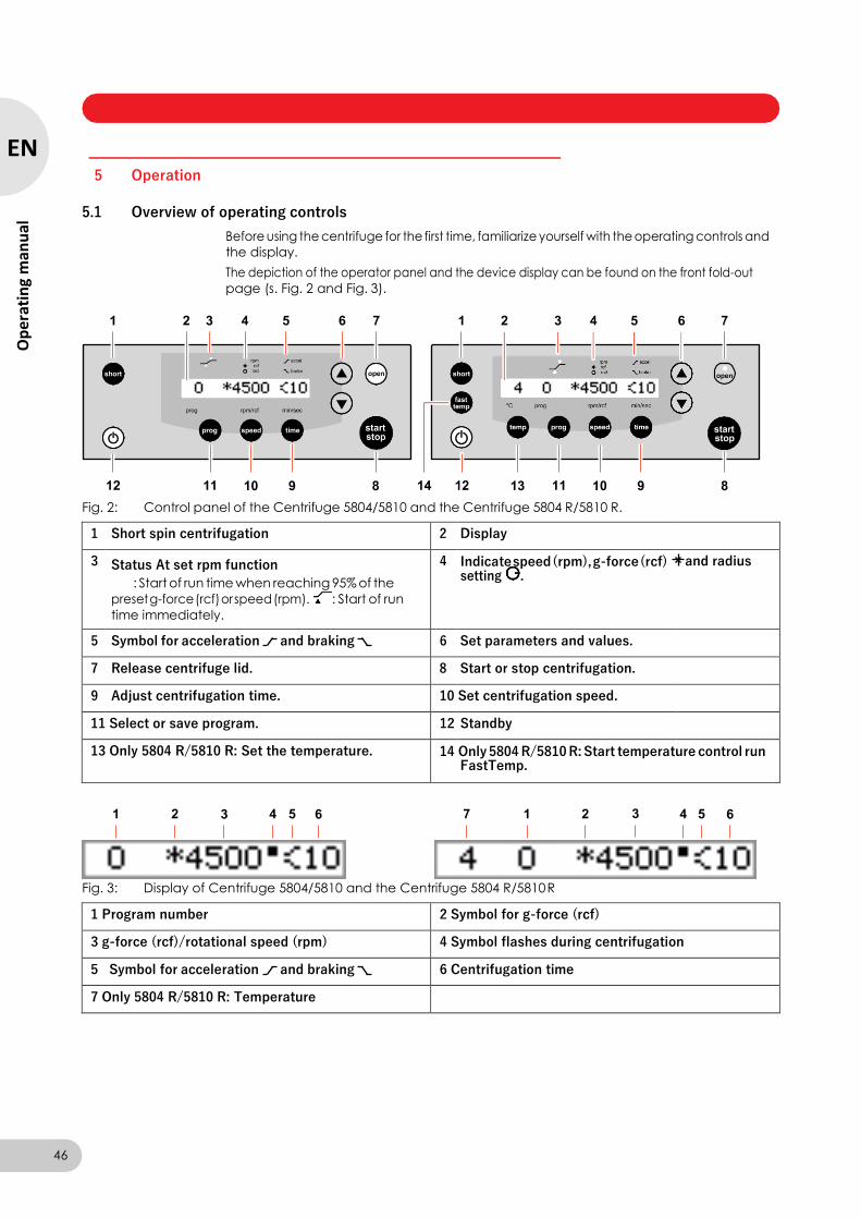
Centrifuge 5804/5804 R/5810/5810 R — Operating manual
5 Operation
5.1 Overview of operating controls
Before using the centrifuge for the first time, familiarize yourself with the operating controls and
the display.
The depiction of the operator panel and the device display can be found on the front fold-out
page (s. Fig. 2 and Fig. 3).
Fig. 2: Control panel of the Centrifuge 5804/5810 and the Centrifuge 5804 R/5810 R.
1 Short spin centrifugation 2 Display
3 Status At set rpm function
: Start of run time when reaching 95% of the
preset g-force (rcf) or speed (rpm). : Start of run
time immediately.
4 Indicate speed (rpm), g-force (rcf) setting .
and radius
5 Symbol for acceleration and braking 6 Set parameters and values.
7 Release centrifuge lid. 8 Start or stop centrifugation.
9 Adjust centrifugation time. 10 Set centrifugation speed.
11 Select or save program. 12 Standby
13 Only 5804 R/5810 R: Set the temperature. 14 Only 5804 R/5810 R: Start temperature control run FastTemp.
Fig. 3: Display of Centrifuge 5804/5810 and the Centrifuge 5804 R/5810 R
1 Program number 2 Symbol for g-force (rcf)
3 g-force (rcf)/rotational speed (rpm) 4 Symbol flashes during centrifugation
5 Symbol for acceleration and braking 6 Centrifugation time
7 Only 5804 R/5810 R: Temperature
46
EN
Op
erat
ing
man
ual
Centrifuge 5804/5804 R/5810/5810 R — Operating manual
The display of the centrifugation parameters changes depending upon the condition of the
device:
• Rotor stop: display of set values.
• Centrifugation: display of actual values.
When you press the temp, time or speed keys during centrifugation, the respective set value is displayed for 2.5 seconds.
Please also read the precise description of the individual functions (see p. 56).
5.2 Preparing for centrifugation
5.2.1 Switching on the centrifuge
1. Switch on the centrifuge using the mains power switch or the standby key.
2. Open the closed centrifuge lid by pressing the open key.
The parameter settings of the last run are displayed.
5.2.2 Inserting the rotor
Requirement
When attaching the rotor to or releasing it from the motor shaft, the temperature of the rotor and
motor shaft must be within the range of 10 –30°C.
Swing-bucket rotors: Before inserting or removing the rotor, remove the carriers and grip the
rotor by the rotor cross with both hands.
F-35-48-17: Before inserting or removing the rotor, remove the sleeves and grip the rotor with
both hands.
1. Fit the rotor vertically on the motor shaft.
2. Insert the supplied rotor key into the rotor nut.
Rotor cross A-4-81: Use the special rotor key.
3. Turn rotor key clockwise until the rotor nut is firmly tightened.
5.2.3 Automatic rotor detection
The centrifuge has automatic rotor detection. It detects a newly inserted rotor during
centrifugation and displays its maximum g-force (rcf)/speed (rpm) for approx. 2 seconds. The set
g-force (rcf)/speed (rpm) is automatically limited to the maximum permissible value of the rotor, if
necessary.
If you start centrifuging immediately after a rotor change, the centrifuge has not carried out an
automatic rotor detection yet. The speed set for the previous rotor may exceed the maximum permitted speed for the new rotor. In this case the centrifuge stops after the automatic rotor
detection. SPEED is flashing in the display. If you have started a program run, the program
number is set to zero.
You can now restart centrifugation with the automatically limited g-force (rcf)/speed (rpm) or
adjust it.
After a rotor change and before centrifugation, carry out a short short-spin run for rotor detection
(see p. 54).
Always check the set g-force (rcf)/speed (rpm) after a rotor change and adjust it if necessary.
47
EN
Op
erating m
anu
al
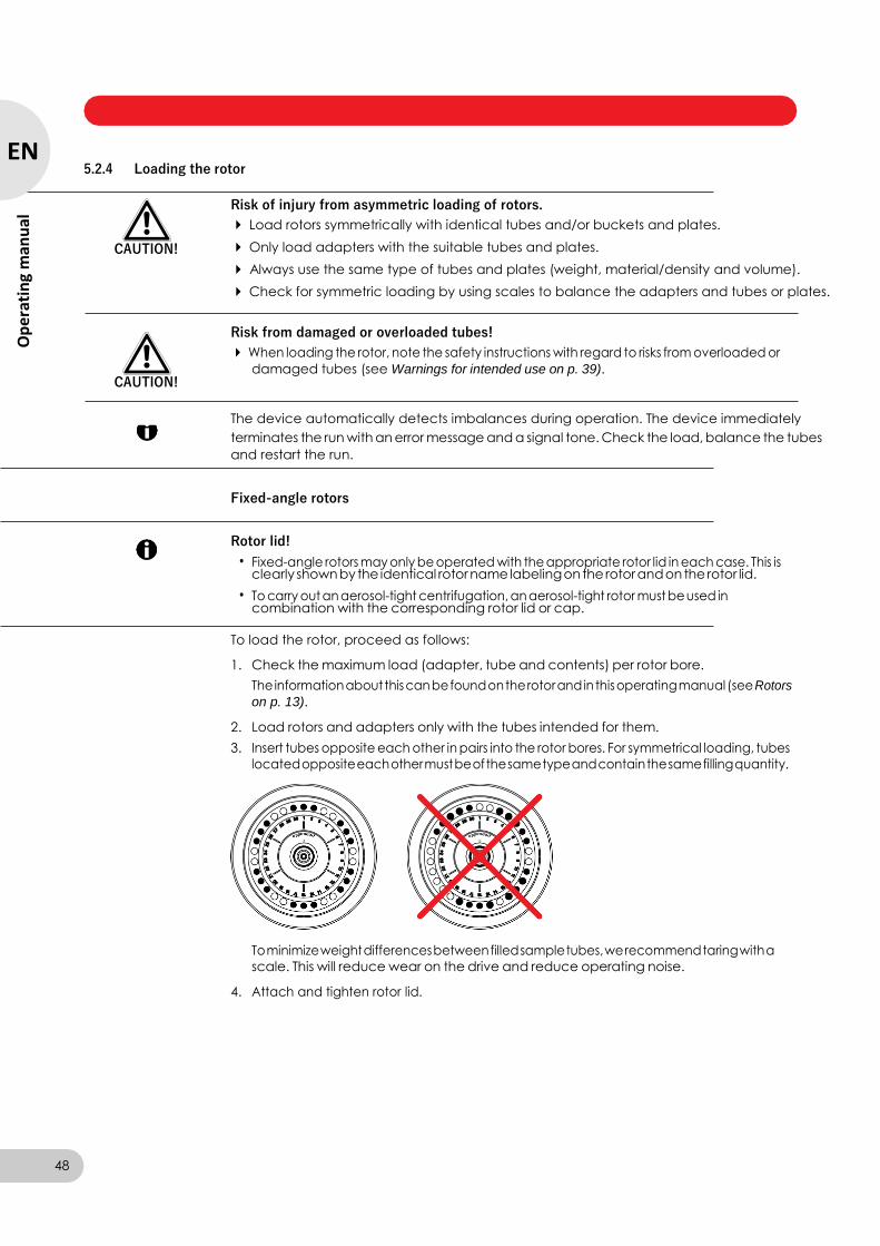
Centrifuge 5804/5804 R/5810/5810 R — Operating manual
5.2.4 Loading the rotor
CAUTION!
Risk of injury from asymmetric loading of rotors.
Load rotors symmetrically with identical tubes and/or buckets and plates.
Only load adapters with the suitable tubes and plates.
Always use the same type of tubes and plates (weight, material/density and volume).
Check for symmetric loading by using scales to balance the adapters and tubes or plates.
CAUTION!
Risk from damaged or overloaded tubes!
When loading the rotor, note the safety instructions with regard to risks from overloaded or
damaged tubes (see Warnings for intended use on p. 39).
The device automatically detects imbalances during operation. The device immediately
terminates the run with an error message and a signal tone. Check the load, balance the tubes
and restart the run.
Fixed-angle rotors
Rotor lid!
• Fixed-angle rotors may only be operated with the appropriate rotor lid in each case. This is clearly shown by the identical rotor name labeling on the rotor and on the rotor lid.
• To carry out an aerosol-tight centrifugation, an aerosol-tight rotor must be used in combination with the corresponding rotor lid or cap.
To load the rotor, proceed as follows:
1. Check the maximum load (adapter, tube and contents) per rotor bore.
The information about this can be found on the rotor and in this operating manual (see Rotors
on p. 13).
2. Load rotors and adapters only with the tubes intended for them.
3. Insert tubes opposite each other in pairs into the rotor bores. For symmetrical loading, tubes
located opposite each other must be of the same type and contain the same filling quantity.
To minimize weight differences between filled sample tubes, we recommend taring with a
scale. This will reduce wear on the drive and reduce operating noise.
4. Attach and tighten rotor lid.
48
EN
Op
erat
ing
man
ual
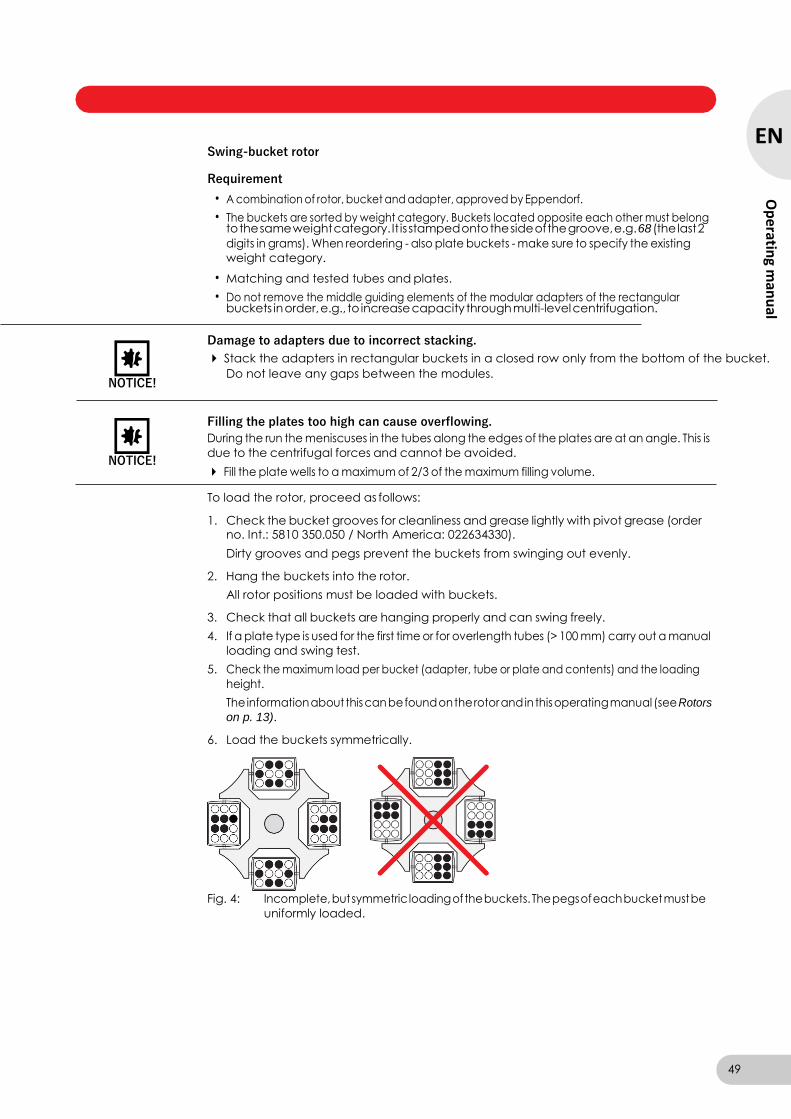
Centrifuge 5804/5804 R/5810/5810 R — Operating manual
Swing-bucket rotor
Requirement
• A combination of rotor, bucket and adapter, approved by Eppendorf.
• The buckets are sorted by weight category. Buckets located opposite each other must belong to the same weight category. It is stamped onto the side of the groove, e.g. 68 (the last 2
digits in grams). When reordering - also plate buckets - make sure to specify the existing
weight category.
• Matching and tested tubes and plates.
• Do not remove the middle guiding elements of the modular adapters of the rectangular buckets in order, e.g., to increase capacity through multi-level centrifugation.
NOTICE!
Damage to adapters due to incorrect stacking.
Stack the adapters in rectangular buckets in a closed row only from the bottom of the bucket.
Do not leave any gaps between the modules.
NOTICE!
Filling the plates too high can cause overflowing.
During the run the meniscuses in the tubes along the edges of the plates are at an angle. This is
due to the centrifugal forces and cannot be avoided.
Fill the plate wells to a maximum of 2/3 of the maximum filling volume.
To load the rotor, proceed as follows:
1. Check the bucket grooves for cleanliness and grease lightly with pivot grease (order no. Int.: 5810 350.050 / North America: 022634330).
Dirty grooves and pegs prevent the buckets from swinging out evenly.
2. Hang the buckets into the rotor.
All rotor positions must be loaded with buckets.
3. Check that all buckets are hanging properly and can swing freely.
4. If a plate type is used for the first time or for overlength tubes (> 100 mm) carry out a manual
loading and swing test.
5. Check the maximum load per bucket (adapter, tube or plate and contents) and the loading
height.
The information about this can be found on the rotor and in this operating manual (see Rotors
on p. 13).
6. Load the buckets symmetrically.
Fig. 4: Incomplete, but symmetric loading of the buckets. The pegs of each bucket must be
uniformly loaded.
49
EN
Op
erating m
anu
al
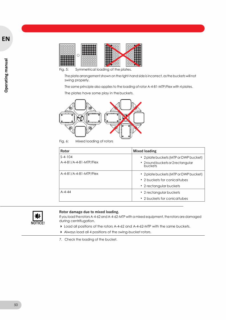
Centrifuge 5804/5804 R/5810/5810 R — Operating manual
Fig. 5: Symmetrical loading of the plates.
The plate arrangement shown on the right-hand side is incorrect, as the buckets will not
swing properly.
The same principle also applies to the loading of rotor A-4-81-MTP/Flex with 4 plates.
The plates have some play in the buckets.
Fig. 6: Mixed loading of rotors
Rotor Mixed loading
S-4-104
A-4-81/A-4-81-MTP/Flex
• 2 plate buckets (MTP or DWP bucket)
• 2 round buckets or 2 rectangular buckets
A-4-81/A-4-81-MTP/Flex • 2 plate buckets (MTP or DWP bucket)
• 2 buckets for conical tubes
• 2 rectangular buckets
A-4-44 • 2 rectangular buckets
• 2 buckets for conical tubes
NOTICE!
Rotor damage due to mixed loading.
If you load the rotors A-4-62 and A-4-62-MTP with a mixed equipment, the rotors are damaged
during centrifugation.
Load all positions of the rotors A-4-62 and A-4-62-MTP with the same buckets.
Always load all 4 positions of the swing-bucket rotors.
7. Check the loading of the bucket.
50
EN
Op
erat
ing
man
ual
Centrifuge 5804/5804 R/5810/5810 R — Operating manual
5.2.5 Closing the centrifuge lid
CAUTION!
Centrifuge lid can crush fingers. Keep hands clear.
When opening or closing the device lid, do not reach between the lid and device or into the
latching mechanism of the lid.
Always open the centrifuge lid completely to prevent it from falling.
1. Check the correct attachment of the rotor and rotor lid.
2. Push down the centrifuge lid until the lid latch engages and the lid is automatically closed.
The centrifuge will close automatically.
The open key lights up blue. The symbol appears in the display.
5.3 Cooling (only 5804 R/5810 R)
5.3.1 Temperature adjustment
Select the temperature setting using the temp key.
Set the temperature using the arrow keys between -9°C and +40°C.
5.3.2 Temperature display
If the rotor is stopped: Set temperature
During centrifugation: Actual temperature
5.3.3 Temperature monitoring
After the set temperature has been reached, the centrifuge reacts to temperature deviations
during centrifugation as follows:
Deviation from set value Action
± 3 °C Temperatures on the display are flashing.
± 5 °C Periodic warning tone. Centrifugation is
stopped automatically.
5.3.4 FastTemp
This function can be used to start a temperature control run directly without samples with a rotor
and temperature-specific speed in order to quickly adjust the rotor chamber, including the rotor,
buckets and adapters, to the previously set nominal temperature.
Requirement
• The centrifuge is switched on.
• The rotor and rotor lid are properly attached.
• The centrifuge lid is closed.
• The temperature and g-force (rcf)/speed (rpm) are set for the subsequent centrifugation (see Centrifuging on p. 53).
1. Press the fast temp key.
The display shows from left to right: actual temperature value, FT, g-force (rcf)/speed (rpm)
and -- (time).
The temperature control run automatically ends when the set temperature has been reached.
A periodic signal tone sounds.
2. Press the start/stop key to terminate the temperature control run early.
51
EN
Op
erating m
anu
al
Centrifuge 5804/5804 R/5810/5810 R — Operating manual
After the set temperature has been reached and the temperature control run is complete, the
centrifuge keeps the rotor chamber with the centrifuge lid closed at the set target temperature if
the temperature is below the ambient temperature. However, independent of the target
temperature, 4 °C must be met via this continuous cooling in order to prevent the rotor chamber
from freezing.
The centrifuge stops the cycle automatically if the rotor or the buckets have reached the set
temperature. Therefore, there may be a delay between the display of the set temperature and the
automatic end of the temperature control run.
When using aerosol-tight buckets, always carry out a FastTemp run at low temperatures without
a cap. There is a danger otherwise of the caps becoming fixed by suction due to a vacuum. Do not pull on the sealing clamps or hooks to loosen the cap. Adjust the temperature of the buckets
to room temperature so that the caps can be removed easily.
5.3.5 Continuous cooling
If the rotor stops, the rotor chamber will be maintained at the target temperature if the following
requirements have been met:
• The centrifuge is switched on.
• The centrifuge lid is closed.
• The set temperature is lower than the ambient temperature.
• The centrifuge is not in standby mode.
During continuous cooling the following applies:
• The set and actual temperature are displayed alternately.
• Irrespective of the set temperature, the temperature does not go below 4 °C to prevent the rotor chamber from freezing and from increased condensation in the device.
• The temperature adjustment is slower because the rotor does not rotate during this process. To end continuous cooling, open the centrifuge lid or press the standby key.
If the centrifuge is not used for more than 8 hours, the continuous cooling is switched off
automatically (ECO shut-off). The device then switches to standby mode. This protects against
ice formation in the rotor chamber and increased condensation in the device. The display shows Standby off and the measured temperature in the rotor chamber. With FastTemp you can quickly reach the desired temperature again (see p. 51).
You can also change from automatically switching off continuous cooling after 8 hours (ECO
shut-off) to unlimited continuous cooling.
NOTICE!
Ice formation and compressor overheating during continuous cooling.
Switch the centrifuge off regularly to eliminate any ice formation by thawing.
Regularly remove condensation from the rotor chamber using a soft, absorbent cloth.
Empty and clean the condensation water tray regularly.
1. When the centrifuge lid is opened, press the temp and prog keys simultaneously.
Standby 8h appears in the display.
2. Press the fast temp key immediately.
Endless operation for continuous cooling is activated. Standby endless appears in the
display.
3. To change back to Standby 8h, repeat the process.
52
EN
Op
erat
ing
man
ual
Centrifuge 5804/5804 R/5810/5810 R — Operating manual
5.4 Centrifuging
CAUTION!
Danger due to incorrectly loaded rotors or damaged or overloaded tubes
Before commencing centrifugation, follow the safety instructions relating to risks from
asymmetrically loaded and/or overloaded rotors and from overloaded, damaged and/or open
tubes (see Warnings for intended use on p. 39).
CAUTION!
Risk of injury from improperly attached rotors, rotor lids and caps.
Only centrifuge with firmly tightened rotor and rotor lid as well as with inserted carriers,
buckets and correctly closed caps.
If unusual noises occur when the centrifuge starts, the rotor, the rotor lid or a cap may not be properly secured. Stop centrifugation immediately by pressing the start/stop key.
Each of the centrifuging variants described here must be preceded by the preparation described
above (see Preparing for centrifugation on p. 47).
5.4.1 Centrifuging with preset time
Perform the following steps in the sequence described.
1. Speed (rpm) setting: press once. g-force (rcf) setting: press repeatedly until the symbol
additionally appears in the display.
The displayed g-force (rcf)/speed (rpm) flashes and can be set with the arrow keys.
For the g-force (rcf) setting also check the set radius (see Rotors on p. 13), (see Setting the
radius on p. 56).
2. Use the arrow keys to set the g-force (rcf)/speed (rpm).
The new set value appears in the display.
3. Select the runtime setting and set it with the arrow keys.
4. Only 5804 R/5810 R: Select the temperature setting and set it with the arrow keys.
5. Start centrifugation.
• blinks in the display when the rotor is running.
• Only 5804 R/5810 R: The current temperature is displayed.
• The current g-force (rcf)/speed (rpm) of the rotor is displayed.
• You can display all set values for 2.5 s by pressing a parameter key (Temp, Speed, Time).
• You can terminate centrifugation early by pressing the start/stop key.
• After completion of the set time, the centrifuge stops automatically.
• During braking the elapsed centrifugation time is displayed in a flashing manner.
6. Open the centrifuge lid as soon as the key lights up.
During the run, you can change the total run time, the temperature (only Centrifuge 5804 R/ 5810 R) and the g-force (rcf)/ speed (rpm) as well as the acceleration time and the braking time.
The new parameters are adopted immediately. The time which has already elapsed is considered
in the newly set total run time. Note that the shortest new total runtime which can be set is the
time which has already elapsed plus 2 minutes.
53
EN
Op
erating m
anu
al
Centrifuge 5804/5804 R/5810/5810 R — Operating manual
5. Open the centrifuge lid as soon as the key is illuminated.
5.4.2 Centrifuging in continuous operation
Perform the following steps in the sequence described.
1. Set the g-force (rcf)/speed (rpm) and possibly the temperature as previously described
(see p. 53).
2. Select the runtime setting.
3. Set continuous operation below 1 min or above 99 min.
In the display indicates continuous run.
4. Start centrifugation.
• blinks in the display when the rotor is running.
• If the centrifuge runs for more than 99 min, 99. appears in the display.
• Only 5804 R/5810 R: The current temperature is displayed.
• The current g-force (rcf)/speed (rpm) of the rotor is displayed.
5. End centrifugation after the desired time.
• During braking the elapsed centrifugation time is displayed flashing.
6. Open the centrifuge lid as soon as the key lights up.
5.4.3 Short spin centrifugation
You can carry out a short spin centrifugation with the currently set or with the maximum
g-force (rcf)/ speed (rpm) of the used rotor.
Setting the speed option
Press and hold down the key with the centrifuge lid open.
One of the following options appears in the display:
rpm max: the rotor accelerates up to its maximum g-force (rcf)/speed (rpm)
(see Rotors on p. 13).
200 - rpm: the rotor only accelerates up to its set g-force (rcf)/speed (rpm).
Press and hold down the key for more than 3 s with the centrifuge lid open to switch
between the rpm max and 200 - rpm options.
The selected option appears in the display for 2 s and is retained.
Starting the short spin centrifugation
1. If 200 - rpm is set, set the g-force (rcf)/ speed (rpm) for the short spin centrifugation
(see p. 53).
2. Only 5804 R/5810 R: Set the temperature (see p. 53). 3. Keep the key pressed to start the short spin centrifugation.
• SH appears in the display while the rotor is running.
• The time is counted upwards in seconds.
4. Release to end the short spin centrifugation.
During the braking process, centrifuging can be restarted up to two more times by pressing the
short key again.
6. Remove the centrifuging material.
54
EN
Op
erat
ing
man
ual
Centrifuge 5804/5804 R/5810/5810 R — Operating manual
5.4.4 Removing the rotor
Requirement
When attaching the rotor to or releasing it from the motor shaft, the temperature of the rotor and
motor shaft must be within the range of 10 –30°C.
Swing-bucket rotors: Before inserting or removing the rotor, remove the carriers and grip the
rotor by the rotor cross with both hands.
F-35-48-17: Before inserting or removing the rotor, remove the sleeves and grip the rotor with
both hands.
5.4.5 Standby mode
1. Turn the rotor nut counterclockwise using the rotor key.
2. Remove the rotor by lifting it vertically.
3. Only 5804 R/5810 R: Switch off the centrifuge after use and empty the condensation water tray. Leave centrifuge lid fully opened and protect it against closing.
You can switch between standby mode and ready state at any time when centrifugation is not
performed by pressing the standby key.
Standby mode
• The display expires.
• The standby key lights up in red.
• Only 5804 R/5810 R: The rotor chamber is not cooled (see Continuous cooling on p. 52).
Ready state
• The centrifugation parameters are displayed.
• The standby key lights up in green.
• Only 5804 R/5810 R: The rotor chamber is cooled when the centrifuge lid is closed (see Continuous cooling on p. 52).
55
EN
Op
erating m
anu
al
Centrifuge 5804/5804 R/5810/5810 R — Operating manual
6 Operating controls and function
6.1 Setting the radius
When you control the rotational speed via the g-force (rcf, RCF), and not via the speed (rpm), the
internal conversion of speed to g-force takes place by default with the largest radius of the used
rotor (see Rotors on p. 13). You can adapt this radius to an applied adapter:
1. Press several times until the symbol also appears in the display.
The current radius flashes.
2. Set the new radius.
3. Wait for 3 seconds (if the rotor is stopped: 10 seconds).
The changed g-force appears.
6.2 Setting the acceleration and braking times
You can set the acceleration and braking time in the levels 0 to 9 (see Tab. on p. 70). Level 9 is
preset (shortest acceleration and braking time).
1. Press twice until the symbol for acceleration level (accel) appears in the display.
2. Select acceleration level 0 to 9.
3. Press once until the symbol for braking level (brake) appears in the display.
4. Select braking level 0 to 9.
Braking level (brake) 0 corresponds to free deceleration.
The device only shows the and symbols continually when levels 0 to 8 have been set.
6.3 Setting the start of run time (At set rpm)
The centrifuge can count down the set time either immediately from the start of centrifugation or
only once 95% of the specified g-force (rcf)/speed (rpm) has been reached (At set rpm). The
respective setting is indicated by the flashing triangle in the symbol above the display:
At set rpm: the set time is counted down once 95% of the specified g-force (rcf)/ speed (rpm) has been reached.
Requirement
The centrifuge lid is open.
When pressing the key, both triangles of the symbol will flash in turn.
Preset time: the set time is counted down immediately after the start of
centrifugation.
Hold down this key for at least 4 s to switch between the two settings,
56
EN
Op
erat
ing
man
ual
Centrifuge 5804/5804 R/5810/5810 R — Operating manual
6.4 Saving the program
You can save the current centrifugation parameters and functions (At set rpm, acceleration and
braking times and radius) under up to 35 program numbers.
Requirement
Rotor stop.
1. Check the parameters and functions to be saved.
2. Press key twice.
The first free program number appears with P... in the display.
3. Select the program number (1...9,A...Z).
4. Press and hold key for 2 seconds.
ok appears in the display. The current centrifugation parameters and functions are saved
under the selected program number.
When you want to overwrite a saved program, you have to delete it before saving the new
parameters (see Deleting the program on p. 57).
6.5 Loading the program
Requirement
• Rotor stop.
• 0: centrifugation parameters and functions of the last run.
• 1...9, A...Z: stored programs.
2. Select the program number.
3. Closed centrifuge lid: centrifugation starts with the loaded centrifugation parameters and
functions.
When the centrifuge lid is open, you can press the start/stop key to return to program 0 or exit the programming mode.
If you change the centrifugation parameters during a run with a stored program, the centrifuge
changes to program 0. The stored program remains unchanged.
You can also exit the stored program by loading program 0.
6.6 Deleting the program
Requirement
• Rotor stop.
• The centrifuge lid is open.
1. Press once.
The program number flashes.
2. Select the program number.
3. Within 10 seconds, keep key pressed for 2 seconds
The following text appears in the display: cleared.
The selected program is deleted. You can save new centrifugation parameters and functions
under this program number.
1. Press once.
Program number flashes:
57
EN
Op
erating m
anu
al
Centrifuge 5804/5804 R/5810/5810 R — Operating manual
6.7 Special functions
6.7.1 Display operating hours
Requirement
Rotor stop.
Press both keys simultaneously.
The previous total run time of the centrifuge (in hours) appears in the display
6.7.2 Switching on/off the warning signal
Press both keys simultaneously to change the setting.
Alarm on or Alarm off appears in the display after 2 s.
6.7.3 Exiting the service functions
Press both keys simultaneously to exit a service program called by mistake.
6.7.4 Controlling the centrifuge via the serial interface (optional)
Optionally, you can also control all centrifuge functions via a serial interface (RS 232 c). For this a
retrofit must be carried out by Eppendorf Service. Only devices verified according to IEC 950
must be connected to the serial interface.
58
EN
Op
erat
ing
man
ual
Centrifuge 5804/5804 R/5810/5810 R — Operating manual
7.1 Maintenance
WARNING!
Danger of crushing if the centrifuge lid falls down due to a defective gas spring.
A defective gas spring is an insufficient support for the centrifuge lid.
Make sure that the centrifuge lid can be opened completely and that it will remain in this
position.
Regularly check the gas spring for its proper function.
Have defective gas springs replaced immediately.
We recommend that the gas springs be replaced every 2 years by a service technician.
We recommend that the centrifuge with the associated rotors be checked at the latest every 12
months by Technical Service during maintenance. Observe the relevant national regulations.
7.2 Prepare cleaning/disinfection
Clean all accessible surfaces of the device and the accessories at least weekly and when
contaminated.
Clean the rotor regularly. This way the rotor is protected and the durability is prolonged.
Furthermore, observe the notes on decontamination (see Decontamination before shipment
on p. 62) when the device is sent to the authorized Technical Service for repairs.
The procedure described in the following chapter applies to the cleaning as well as to the
disinfection or decontamination. The table below describes the steps required on top of this:
Cleaning Disinfecting/decontamination
1. Use a mild cleaning fluid to clean the
accessible surfaces of the device and the
accessories.
2. Carry out the cleaning as described in the
following chapter.
1. Choose the disinfection method which
corresponds to the legal regulations and
guidelines in place for your range of
application. For example, use alcohol
(ethanol, isopropanol) or alcohol-based
disinfectants.
2. Carry out the disinfection or
decontamination as described in the
following chapter.
3. Then clean the device and the accessories.
If you have any further questions regarding the cleaning and disinfection or decontamination or
regarding the cleaning fluid to be used, contact the Eppendorf AG Application Support. The contact details are provided on the back of this manual.
7 Maintenance
59
EN
Op
erating m
anu
al

Centrifuge 5804/5804 R/5810/5810 R — Operating manual
7.3 Cleaning/disinfection
DANGER!
Electric shock as a result of penetration of liquid.
Switch off the device and disconnect the power plug before starting cleaning or disinfection
work.
Do not allow any liquids to penetrate the inside of the housing.
Do not spray clean/spray disinfect the housing.
Only plug the device back in if it is completely dry, both inside and outside.
NOTICE!
Damage from the use of aggressive chemicals.
Do not use any aggressive chemicals on the device or its accessories, such as strong and
weak bases, strong acids, acetone, formaldehyde, halogenated hydrocarbons or phenol.
If the device becomes contaminated with aggressive chemicals, clean it immediately with a
mild cleaning agent.
NOTICE!
Corrosion due to aggressive cleaning agents and disinfectants.
Do not use corrosive cleaning agents, aggressive solvents or abrasive polishes.
Do not incubate the accessories in aggressive cleaning agents or disinfectants for prolonged
periods.
NOTICE!
Damage from UV and other high-energy radiation.
Do not use UV, beta, gamma, or any other high-energy radiation for disinfecting.
Avoid storage in areas with strong UV radiation
Autoclaving
Except for the rotor crosses A-4-81, S-4-72 and S-4-104, all rotors, rotor lids, buckets, carriers,
caps and adapters can be autoclaved (121 °C, 20 min).
For guaranteeing the aerosol tightness, after a maximum of50 autoclaving cycles the gaskets of
the caps and the QuickLock rotor lid have to be exchanged.
Do not use any stained, porose or otherwise defective gaskets. Also note the operating manual of
the centrifuge and the supplement sheet on aerosol-tight centrifugation delivered together with
the aerosol-tight rotors.
The aerosol-tight rotor FA-45-30-11 can be autoclaved at 142°C for 2 hours to destroy prions. In
this case note that the rotor lid must be replaced after each autoclaving.
Aerosol tightness
Check that the seals are intact before use.
Replace the rotor lid of the aerosol-tight rotors when the sealing rings on the lid screw and in the
lid groove become worn. The sealing rings require regular care to protect the rotors.
Aerosol-tight rotors should never be stored with lids screwed on!
In order to prevent damage, lightly lubricate the lid thread of the aerosol-tight rotors with pivot
grease (order no. Int.: 5810 350.050/North America: 022634330).
Swing-bucket rotor
• Before cleaning the rotor, remove old pivot grease from grooves and pivots.
• Make sure that the grooves and pivots are clean. Dirty grooves and pivots prevent the buckets from swinging out evenly.
• After cleaning, lubricate the pivots of the rotor and the grooves of the buckets with pivot grease (order no. Int.: 5810 350.050/North America: 022634330) so that the carriers can
move freely in a swinging manner.
60
EN
Op
erat
ing
man
ual
Centrifuge 5804/5804 R/5810/5810 R — Operating manual
7.3.1 Cleaning and disinfecting the device
1. Open the lid. Switch off the device with the mains switch. Disconnect the power plug from the
power supply.
2. Loosen the rotor nut by turning the rotor key counterclockwise.
3. Remove the rotor.
4. Clean and disinfect all accessible surfaces of the device, including the power cable, using a
damp cloth and the recommended cleaning agents.
5. Thoroughly clean the rubber seal of the rotor chamber with water.
6. Rub the dry rubber seal with glycerine or talcum powder to prevent it from becoming brittle.
Other components of the device, such as the lid latch, lid springs, motor shaft and rotor cone,
must not be lubricated.
7. Clean the motor shaft with a soft, dry and lint-free cloth. Do not lubricate the motor shaft.
8. Check the motor shaft for damage.
9. Inspect the device for corrosion and damage.
10. Leave the centrifuge lid open when the device is not being used.
11. Only connect the device to the power supply if it is fully dry inside and out.
7.3.2 Cleaning and disinfecting the rotor
Detailed instructions for cleaning and maintenance can be found in "Fixed-Angle Rotor - Basic
Inspection" and "Swing-Bucket Rotor - Basic Inspection".
After every 200 runs, the centrifuge displays clean rotor three times to remind you about the
regular rotor cleaning.
1. Inspect the rotor and accessories for damage and corrosion. Do not use any damaged rotors
or accessories.
2. Clean and disinfect the rotors and accessories with the recommended cleaning agents.
3. Use a bottle brush to clean and disinfect the rotor bores.
4. Rinse the rotors and accessories thoroughly with distilled water. Rinse the rotor bores of
fixed-angle rotors particularly thoroughly.
Do not immerse the rotor in liquid as liquid can get trapped inside the cavities.
5. Place rotors and accessories on a cloth to dry. Place fixed-angle rotors with the rotor bores
facing downwards to allow the bores to dry as well.
6. Clean the rotor cone with a soft, dry and lint-free cloth. Do not lubricate the rotor cone.
7. Inspect the rotor cone for damage.
8. Place the dry rotor onto the motor shaft.
9. Tighten the rotor nut firmly by turning it clockwise with the rotor key.
10. Load the fixed-angle rotor with the cleaned adapters or the swing-bucket rotor with the
cleaned buckets and adapters, if necessary.
11. Leave the rotor lid open when the rotor is not being used.
61
EN
Op
erating m
anu
al
Centrifuge 5804/5804 R/5810/5810 R — Operating manual
7.4 Additional service instructions for Centrifuge 5804 R/5810 R
Empty and clean the condensation water tray regularly and especially after liquid spillage in
the rotor chamber. Pull out the condensation water tray at the front right under the device.
The condensation water outlet also needs to be cleaned on a regular basis, e.g., using a
bottle brush.
Regularly clear the rotor chamber of ice formations via thawing, either by leaving the
centrifuge lid open or carrying out a brief temperature control run at approx. 30°C.
Leave the centrifuge lid open when not in use for a long period.
This allows residual moisture to escape. The gas pressure spring is relieved.
Wipe up condensate in the rotor chamber. To do so, use a soft absorbent cloth.
Remove dust deposits from the ventilation slits of the centrifuge using a brush or swab at the
latest every six months. First switch off the device and remove the power plug.
7.5 Glass breakage
When using glass tubes there is a risk of glass breakage in the rotor chamber. The resulting glass
splinters are swirled around in the rotor chamber during centrifugation and have a sandblasting
effect on the rotor and accessories. Fine glass particles can become lodged in the rubber parts
(e.g., the motor sleeve, the sealing of the rotor chamber and the rubber mats of adapters).
NOTICE!
Glass breakage in the rotor chamber
Glass tubes in the rotor chamber may break if the g-force is too high. Broken glass can damage
the rotor, accessories and samples.
Please note the manufacturer's information on the recommended centrifugation parameters
(load and speed).
Effects of glass breakage in the rotor chamber:
• Fine black metal abrasion in the rotor chamber (in metal rotor chambers)
• The surfaces of the rotor chamber and accessories are scratched.
• The chemical resistance of the rotor chamber is reduced.
• Contamination of samples
• Wear on rubber parts
How to proceed in case of glass breakage 1. Remove all splinters and glass powder from the rotor chamber and accessories.
2. Thoroughly clean the rotor and rotor chamber. Thoroughly clean the bores of the fixed-angle
rotors, in particular.
3. If required, replace rubber mats and adapters to prevent any further damage.
4. Regularly check the rotor bores for deposits and damage.
7.6 Decontamination before shipment
If you are shipping the device to the authorized Technical Service for repairs or to your authorized
dealer for disposal please note the following:
WARNING!
Risk to health from contaminated device
1. Follow the instructions in the decontamination certificate, which is available as a PDF on our
website (www.eppendorf.com/decontamination).
2. Decontaminate all the parts you would like to dispatch.
3. Enclose the fully-completed decontamination certificate for returned goods (including the
serial number of the device) with the dispatch.
62
EN
Op
erat
ing
man
ual
Centrifuge 5804/5804 R/5810/5810 R — Operating manual
If the suggested measures repeatedly are not successful, please contact your local Eppendorf
partner.The contact addresses can be found online at www.eppendorf.com/worldwide.
8.1 Resetting the excess current switch
The 230 V and 120 V devices have built-in thermal excess-current switches which function as
(all-pole) fuses. When the overload protection is actuated, these switch the power switch to OFF,
but do not switch it on again automatically.
To switch on the excess current switch again, proceed as follows:
1. Switch off the centrifuge using the power switch.
2. Wait for at least 20 seconds and switch on the centrifuge again.
The excess current switch will be automatically reactivated and the centrifuge is ready for
operation.
8.2 General errors
Symptom/message Cause Remedy
No display. No mains connection. Check the mains connection.
No display. Power failure. Check the mains fuse of the device
(see Resetting the excess current switch
on p. 63).
Check the mains fuse of the laboratory.
Lid of the device cannot
be opened.
Rotor is still running. Wait for rotor to stop.
Lid of the device cannot
be opened.
Power failure. 1. Check the mains fuse of the device
(see Resetting the excess current switch
on p. 63).
2. Check the mains fuse of the laboratory.
3. Activate the emergency lid release
(see p. 65).
Clean rotor 200 runs. Clean the rotor and chamber (see p. 59).
Centrifuge brakes during a short run centrifugation,
although the short key is pressed.
The short key was released briefly more than twice (protective function for the drive).
Press the short key continuously during a short run centrifugation.
8 Troubleshooting
63
EN
Op
erating m
anu
al
Centrifuge 5804/5804 R/5810/5810 R — Operating manual
8.3 Error messages
If one of the following error messages appears, proceed as follows:
1. Remove fault (see Remedy).
2. Press open key to clear the error message.
3. If necessary, repeat centrifugation.
Some errors can have various causes. The actual cause is described in the message in the
device display.
Symptom/message Cause Remedy
No rotor
Centrifuge does not start
up.
No rotor. Insert the rotor.
No rotor
Centrifuge does not start
up.
Error in the drive or in the rotor detection. Switch the centrifuge off and back on
again after > 20 s.
Press Open Centrifuge lid could not be locked. 1. Press the open key.
2. Try again to close centrifuge lid.
Close lid Centrifuge lid not closed properly. Close the centrifuge lid firmly.
Lift lid
The centrifuge lid does
not open.
The centrifuge lid cannot open automatically. Lift the centrifuge lid manually.
IMBAL
The centrifuge shakes
when it starts up and
switches off.
Rotor is loaded asymmetrically. Load the rotor symmetrically (see p. 47).
ROTOR
The centrifuge shakes
when it starts up and
switches off.
Rotor not screwed sufficiently. 1. Tighten the rotor nut (see p. 47).
2. Check the rotor cone and motor shaft for
grooves and damage.
ROTOR
The centrifuge shakes
when it starts up and
switches off.
• Centrifuge was pushed.
• Table is not stable.
Position the centrifuge on a stable table
(see p. 44).
SPEED
Centrifuge switches off.
Nominal speed for rotor too high. Enter the appropriate nominal speed
(see p. 13).
change rotor The maximum service life of the rotor has
been reached. The warning is displayed after
98,000, 99,000 and 99,600 runs (3 times
after each run). After 100,000 runs, it is
displayed after every run.
Contact Technical Service.
Temperature display
flashes.
(only 5804 R/5810 R)
Temperature deviation from the set value: ±3 °C. Check the settings.
Wait until the set temperature has been
reached.
Check unhindered air circulation through
the air slots.
Thaw ice or switch off device and allow it
to cool down.
64
EN
Op
erat
ing
man
ual

Centrifuge 5804/5804 R/5810/5810 R — Operating manual
Symptom/message Cause Remedy
Overtemp
( only 5804 R/5810 R)
Centrifuge switches off
and issues a warning
tone.
Temperature deviation from the set value in
the rotor chamber: ±5 °C. Check the settings.
Check unhindered air circulation through
the air slots.
Thaw ice or switch off device and allow it
to cool down.
Clear memory Program memory full. Delete some programs (see p. 57).
Interrupt Power failure during a run. Check the mains connection.
Error 1 Error in speed measuring system. If this error message appears again, test
with a different rotor.
Error 2 Imbalance sensor faulty. Repeat the run.
Error 3 Error in speed measuring system. Insert rotor and screw tight.
Error 3 Error in speed measuring system. Allow the centrifuge to stand for 12 min when switched on until the open key
lights up.
Error 4 Lid latch sensor faulty. Switch the centrifuge off and back on
again after > 20 s.
Error 5 Prohibited opening of lid or lid switch is
defective during a run.
1. Wait for rotor to stop.
2. Open and close again the lid of the
device.
3. Repeat the run.
Error 6 or overload Mains voltage too low. Check the mains voltage.
Error 6 or overload • Converter overloaded.
• Brake faulty.
Switch off centrifuge, allow to cool down
for at least 5 min, and then switch on
again.
Error 8 • Drive fault.
• Rotor loose.
• Motor defective.
1. Wait for rotor to stop.
2. Tighten the rotor.
3. Repeat the run.
Error 9 to Error 25 Electronics fault. Switch the centrifuge off and back on
again after > 20 s.
8.4 Emergency release If the centrifuge lid cannot be opened, you can activate the emergency release manually.
WARNING!
Risk of injury from rotating rotor.
Wait for the rotor to stop before activating the emergency release. The rotor can continue
rotating for up to 8 min.
To check, look through the monitoring glass in the centrifuge lid.
You need the standard rotor key supplied with the centrifuge.
1. Disconnect the power plug.
2. Remove the plastic cover for the emergency release. This is located in the center on the front
side of the device.
3. Insert the rotor key into the hexagonal opening behind until some resistance can be felt.
4. While keeping the rotor key pressed, turn it in a counterclockwise direction.
This will release the centrifuge lid.
5. Open the centrifuge lid.
6. Remove the rotor key and put the plastic covers back on.
65
EN
Op
erating m
anu
al
Centrifuge 5804/5804 R/5810/5810 R — Operating manual
9 Transport, storage and disposal
9.1 Transport The device may only be transported in its original packaging.
Air temperature Relative humidity Atmospheric
pressure
General transport -25 °C –60 °C 10 % –75 % 30 kPa –106 kPa
Air freight -20 °C –55 °C 10 % –75 % 30 kPa –106 kPa
9.2 Storage
Air temperature Relative humidity Atmospheric
pressure
In transport packaging -25 °C – 55 °C 10 % – 75 % 70 kPa – 106 kPa
Without transport
packaging
-5 °C – 45 °C 10 % – 75 % 70 kPa – 106 kPa
9.3 Disposal In case the product is to be disposed of, the relevant legal regulations are to be observed.
Information on the disposal of electrical and electronic devices in the European Community:
Within the European Community, the disposal of electrical devices is regulated by national
regulations based on EU Directive 2002/96/EC pertaining to waste electrical and electronic
equipment (WEEE).
According to these regulations, any devices supplied after August 13, 2005, in the
business-to-business sphere, to which this product is assigned, may no longer be disposed of in
municipal or domestic waste. To document this, they have been marked with the following
identification:
Because disposal regulations may differ from one country to another within the EU, please
contact your supplier if necessary.
In Germany, this is mandatory from March 23, 2006. From this date, the manufacturer has to offer
a suitable method of return for all devices supplied after August 13, 2005. For all devices supplied
before August 13, 2005, the last user is responsible for the correct disposal.
66
EN
Op
erat
ing
man
ual

Centrifuge 5804/5804 R/5810/5810 R — Operating manual
10.1 Power supply
Power connection: 230 V, 50 to 60 Hz
120 V, 60 Hz
Current consumption: 5804/5810 (230 V):
5804/5810 (120 V):
5804 R/5810 R (230 V):
5804 R/5810 R (120 V), 20 A:
5804 R/5810 R (120 V), 15 A:
Power consumption: 5804/5810 (230 V):
5804/5810 (120 V):
5804 R/5810 R (230 V):
5804 R/5810 R (120 V), 20 A:
5804 R/5810 R (120 V), 15 A:
6 A
11 A
9 A/10 A
16 A
12 A
max. 900 W
max. 950 W
max. 1650 W
max. 1650 W
max. 1300 W
EMC: Interference
emission (radio
interference)
EN 61326-1 Class A
EMC: Noise immunity EN 61326
Overvoltage category: II
Fuses: 5804/5810 (230 V):
5804/5810 (120 V):
5804 R/5810 R (230 V):
5804 R/5810 R (120 V), 20 A:
5804 R/5810 R (120 V), 15 A:
Excess current switch 12 A
Excess current switch 12 A
Excess current switch 12 A
Excess current switch 18 A
Excess current switch 15 A
10.2 Ambient conditions
Environment: For indoor use only.
Ambient temperature: 5804/5810:
5804 R/5810 R:
Max. relative humidity: 75%, non-condensing humidity
2 to 40°C
15 to 35°C
Atmospheric pressure: Use up to an altitude of 2000 m above MSL.
Degree of pollution: 2
10 Technical data
67
EN
Op
erating m
anu
al

Centrifuge 5804/5804 R/5810/5810 R — Operating manual
10.3 Weight/dimensions
Dimensions
(W × D × H)
5804 466 × 550 × 337 mm (18.4 × 21.7 × 13.3 in.)
Depth of footprint: 496 mm (19.5 in.)
5804 R 634 × 550 × 342 mm (25.0 × 21.7 × 13.5 in.)
Depth of footprint: 496 mm (19.5 in.)
5810 535 × 608 × 345 mm (21.1 × 21.1 × 13.6 in.)
Depth of footprint: 536 mm (21.1 in.)
5810 R 700 × 608 × 345 mm (27.6 × 23.9 × 13.6 in.)
Depth of footprint: 536 mm (21.1 in.)
Weight excl. rotor 5804 55 kg (121 lb.)
5804 R 80 kg (176 lb.)
5810 68 kg (150 lb.)
5810 R 99 kg (218 lb.)
Rotor
A-4-81
(4 x 500 mL)
A-4-44
(4 x 100 mL)
F-34-6-38
(6 x 85 mL)
Noise level 5804 - < 67 dB(A) < 51 dB(A)
5804 R - < 56 dB(A) < 58 dB(A)
5810 < 65 dB(A) < 65 dB(A) < 53 dB(A)
5810 R < 56 dB(A) < 56 dB(A) < 59 dB(A)
The noise level was measured according to DIN EN ISO 3745 frontally in a sound measuring
room with accuracy class 1 at a distance of 1 m from the device and at lab bench height.
68
EN
Op
erat
ing
man
ual

Centrifuge 5804/5804 R/5810/5810 R — Operating manual
10.4 Application parameters
Run time: 1 to 99 min, adjustable in 1 min increments.
infinite ( )
Temperature (only
5804 R/5810 R):
Relative centrifugal
force (RCF or rcf):
-9 °C to 40 °C
10 to 20,913 x g
adjustable up to 3,000 x g in 10 x g increments, thereafter in 100 x g
increments.
Rotational speed: 200 to 14,000 rpm,
adjustable up to 5,000 rpm in 10 rpm, afterwards in 100 rpm
increments.
Max. load: 5804/5804 R:
5810/5810 R:
Max. kinetic energy: 5804/5810:
5804 R:
5810 R:
4 ×250 mL
4 ×750 mL
19,000 Nm (11,000 rpm)
19,000 Nm (11,000 rpm)
23,000 Nm (12,000 rpm)
Test log mandatory in
Germany:
Permitted density of
the centrifugate
(at max. g-force/rpm
and max. load):
Standardized interface
(optional)
Yes
1.2 g/mL
RS 232 C
69
EN
Op
erating m
anu
al
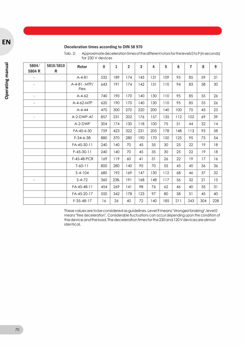
Centrifuge 5804/5804 R/5810/5810 R — Operating manual
Deceleration times according to DIN 58 970
Tab. 2: Approximate deceleration times of the different rotors for the levels 0 to 9 (in seconds)
for 230 V devices
5804/
5804 R
5810/5810
R Rotor 0 1 2 3 4 5 6 7 8 9
- A-4-81 532 189 174 143 131 109 95 85 59 31
- A-4-81- MTP/
Flex
643 191 174 142 131 110 94 83 58 30
- A-4-62 740 190 170 140 130 110 95 85 55 26
- A-4-62-MTP 620 190 170 140 130 110 95 85 55 26
A-4-44 470 300 270 220 200 140 100 75 45 23
- A-2-DWP-AT 857 231 202 176 157 135 112 102 69 39
A-2-DWP 304 174 130 118 100 75 51 44 32 14
FA-45-6-30 759 423 322 231 205 178 148 113 93 58
F-34-6-38 880 370 280 190 170 150 125 95 75 54
FA-45-30-11 240 140 70 45 35 30 25 22 19 18
F-45-30-11 240 140 70 45 35 30 25 22 19 18
F-45-48-PCR 169 119 60 41 31 26 22 19 17 16
T-60-11 800 280 140 95 70 55 45 40 36 36
S-4-104 680 192 169 147 130 112 68 46 37 32
- S-4-72 360 238, 191 168 148 117 56 32 21 15
FA-45-48-11 454 269 141 98 76 62 46 40 35 31
FA-45-20-17 550 342 178 123 97 80 58 51 45 40
F-35-48-17 16 26 40 72 140 185 211 243 304 228
These values are to be considered as guidelines. Level 9 means "strongest braking", level 0
means "free deceleration". Considerable fluctuations can occur depending upon the condition of
the device and the load. The deceleration times for the 230 and 120 V devices are almost
identical.
70
EN
Op
erat
ing
man
ual
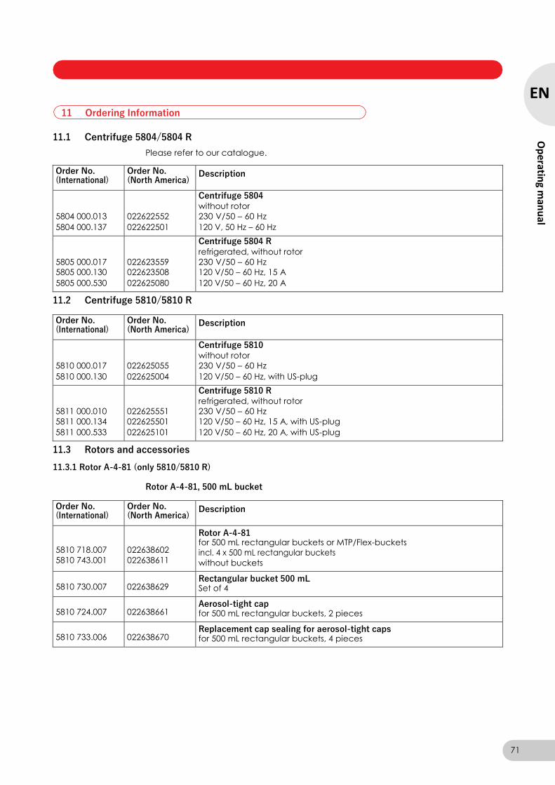
Centrifuge 5804/5804 R/5810/5810 R — Operating manual
11.1 Centrifuge 5804/5804 R
Please refer to our catalogue.
Order No. (International)
Order No. (North America)
Description
Centrifuge 5804 without rotor
5804 000.013 022622552 230 V/50 – 60 Hz
5804 000.137 022622501 120 V, 50 Hz – 60 Hz
Centrifuge 5804 R refrigerated, without rotor
5805 000.017 022623559 230 V/50 – 60 Hz
5805 000.130 022623508 120 V/50 – 60 Hz, 15 A
5805 000.530 022625080 120 V/50 – 60 Hz, 20 A
11.2 Centrifuge 5810/5810 R
Order No. (International)
Order No. (North America)
Description
Centrifuge 5810 without rotor
5810 000.017 022625055 230 V/50 – 60 Hz
5810 000.130 022625004 120 V/50 – 60 Hz, with US-plug
Centrifuge 5810 R refrigerated, without rotor
5811 000.010 022625551 230 V/50 – 60 Hz
5811 000.134 022625501 120 V/50 – 60 Hz, 15 A, with US-plug
5811 000.533 022625101 120 V/50 – 60 Hz, 20 A, with US-plug
11.3 Rotors and accessories
11.3.1 Rotor A-4-81 (only 5810/5810 R)
Rotor A-4-81, 500 mL bucket
Order No. (International)
Order No. (North America)
Description
5810 718.007
5810 743.001
022638602
022638611
Rotor A-4-81 for 500 mL rectangular buckets or MTP/Flex-buckets
incl. 4 x 500 mL rectangular buckets
without buckets
5810 730.007
022638629 Rectangular bucket 500 mL Set of 4
5810 724.007
022638661 Aerosol-tight cap for 500 mL rectangular buckets, 2 pieces
5810 733.006
022638670 Replacement cap sealing for aerosol-tight caps for 500 mL rectangular buckets, 4 pieces
11 Ordering Information
71
EN
Op
erating m
anu
al

Centrifuge 5804/5804 R/5810/5810 R — Operating manual
Order No. (International)
Order No. (North America)
Description
5810 745.004
5810 746.000
5810 720.001
5825 717.007
5810 748.003
5810 721.008
5810 722.004
5810 723.000
5810 739.004
5825 722.000
5810 728.002
022638704
022638707
022638700
022638718
022638721
022638726
022638742
022638769
022638904
022638921
022638785
Adapter for 500 mL rectangular buckets for 20 sample tubes (1.5/2.0 mL, max. Ø 11 mm), set of 2
for 20 blood collection tubes (1.2 – 5 mL, max. Ø 11 mm), set of 2
for 24 tubes (2.6 – 7 mL, max. Ø 13 mm), set of 2
for 18 tubes (5 mL, Monovette, max. Ø 13 mm), set of 2
for 16 blood collection tubes (3 – 15 mL, max. Ø 16 mm), set of 2
for 16 tubes (7 – 17 mL, max. Ø 17.5 mm), set of 2
for 12 conical tubes (15 mL, max. Ø 17.5 mm), set of 2
for 5 conical tubes (50 mL, max. Ø 31 mm), set of 2
for 5 Centriprep Centrifugal Filter Units (max. Ø 31 mm), set of 2
for 1 bottle (180 – 250 mL, max. Ø 62 mm), set of 2
for 1 bottle (400 mL, max. Ø 81 mm), set of 2
5810 734.002
022638688
Replacement rubber mat for adapters for 500 mL rectangular buckets set of 4
5810 735.009
022638696
Replacement clamp for adapters for 500 mL rectangular buckets set of 2
5804 737.008
022654373 Adapter for 50 mL skirted conical tubes, set of 8
5810 729.009
5820 707.003
022638653
022638657
Wide-neck bottle for Rotor A-4-81 400 mL, set of 2 500 mL, rectangular, set of 2
5810 718.309
022664174 Rotor key for Rotor A-4-81
Rotor A-4-81, MTP/Flex carrier
Order No. (International)
Order No. (North America)
Description
5810 725.003
022638807 Rotor A-4-81-MTP/Flex Swing-bucket rotor, incl. 4 MTP/Flex buckets
5810 743.001
022638611
Rotor A-4-81 for 500 mL rectangular buckets or MTP/Flex-buckets without buckets
5810 741.009
5810 742.005
022638840
022638866
Retrofit kit MTP/Flex buckets for Rotor A-4-81 or A-4-81-MTP/Flex for use with IsoRack and cell culture flask adapters as well as MTP and DWP set of 4
set of 2
5825 708.008
5825 709.004
022638980
022638998
IsoRack adapter for 24 x 0.5 mL tubes in the IsoRack, set of 2 for 24 x 1.5/2.0 mL tubes in the IsoRack, set of 2
5825 721.004
022510070
IsoRack starter set for Flex buckets 2 × IsoRack Adapter, 2 × IsoRacks with lid, 2 × cool packs (0 °C IsoPack) for 0.5 mL and 1.5/2.0 mL sample tubes
5825 711.009
5825 713.001
022638947
022638955
Adapter used in A-4-81-MTP/Flex, A-4-62-MTP, A-2-DWP-AT and A-2-DWP
for 96-well PCR plates, set of 2
for 384-well PCR plates, set of 2
72
EN
Op
erat
ing
man
ual

Centrifuge 5804/5804 R/5810/5810 R — Operating manual
Order No. (International)
Order No. (North America)
Description
5825 706.005
022638963
Adapter used in A-4-81-MTP/Flex, A-4-62-MTP and A-2-DWP Combislide Adapter, set of 2
5825 719.000
5825719000
Adapter used in A-4-81-MTP/Flex for 1 cell culture bottle, set of 2
Rotor A-4-81, bucket for conical tubes
Order No. (International)
Order No. (North America)
Description
5825 730.003
022638614 Bucket for A-4-81 for 7 50 mL conical tubes, set of 4
5820 718.005
5820718005
Adapter used in FA-45-6-30 for 15 mL conical tubes, set of 7
11.3.2 Rotor A-4-62 and A-4-62-MTP (only 5810/5810 R)
Rotor A-4-62
Order No. (International)
Order No. (North America)
Description
5810 709.008
022638009 Rotor A-4-62 incl. 4 x 250 mL rectangular buckets
5810 716.004
022638084 Rectangular bucket 250 mL Set of 4
5810 710.006
022638033 Aerosol-tight caps for 250 mL rectangular buckets, set of 2
5810 713.005
022638017
Spare sealing for aerosol-tight caps for 250 mL rectangular buckets Set of 4
5810 751.004
5810 750.008
5810 752.000
5810 753.007
5810 754.003
5810 756.006
5810 757.002
5810 759.005
5810 760.003
5810 761.000
5810 770.009
5810 755.000
5810 758.009
5810 763.002
022638220
022638203
022638246
022638262
022638301
022638327
022638360
022638386
022638408
022638424
022638441
022638289
022638343
022638351
Adapter for 250 mL rectangular buckets
for 16 sample tubes (1.5/2.0 mL, max. Ø 11 mm), set of 2
for 25 tubes (1.2 – 5 mL, max. Ø 11 mm), set of 2
for 15 tubes (2.6 – 7 mL, max. Ø 13 mm), set of 2
for 12 tubes (3 – 15 mL, max. Ø 16 mm), set of 2
for 12 tubes (7 – 17 mL, max. Ø 17.5 mm), set of 2
for 8 tubes (7 – 18 mL, max. Ø 20 mm), set of 2
for 4 tubes (18 – 30 mL, max. Ø 26 mm), set of 2
for 4 tubes (30 – 50 mL, max. Ø 31 mm), set of 2
for 2 tubes (50 – 75 mL, max. Ø 35 mm), set of 2
for 1 tube (80 – 120 mL, max. Ø 45 mm), set of 2
for 1 bottle (180 – 250 mL, max. Ø 62 mm), set of 2
for 9 conical tubes (15 mL, max. Ø 17.5 mm), set of 2
for 3 conical tubes (50 mL, max. Ø 31 mm), set of 2
for 4 conical tubes (50 mL), operation w/o aerosol-tight cap, set of 2
5810 782.007
022638483
Replacement rubber mat for adapters for 250 mL rectangular buckets Set of 4
73
EN
Op
erating m
anu
al
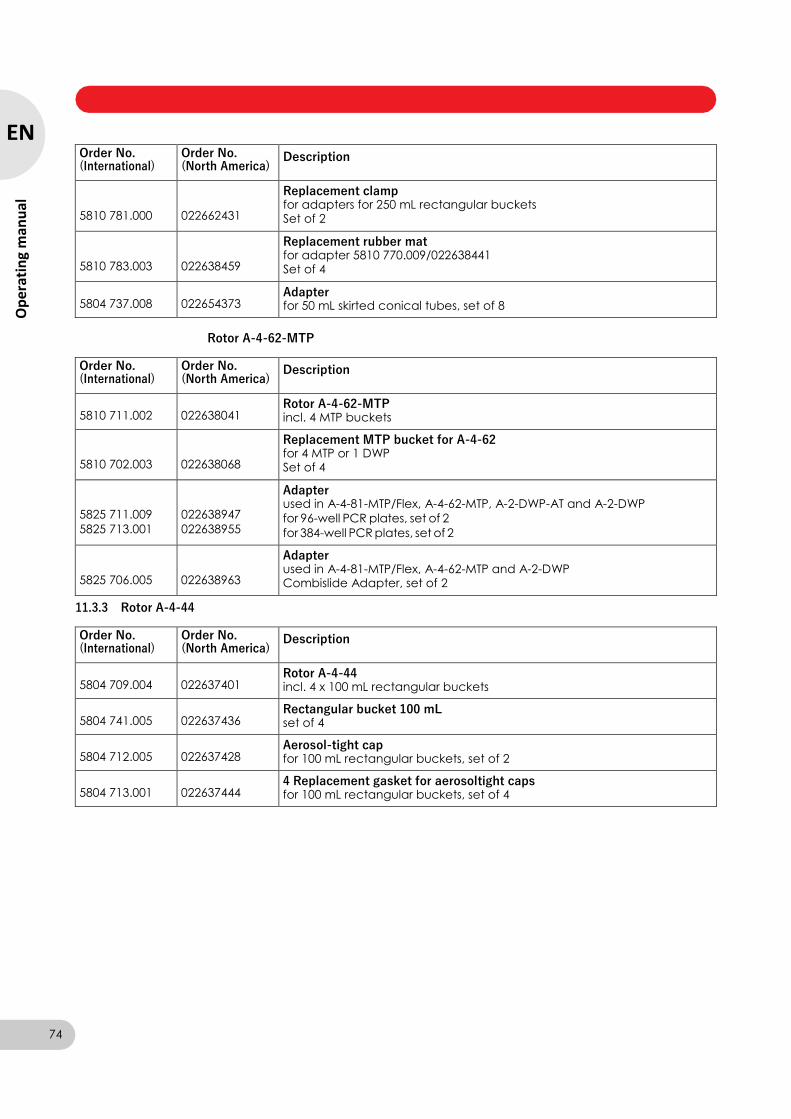
Centrifuge 5804/5804 R/5810/5810 R — Operating manual
Order No. (International)
Order No. (North America)
Description
5810 781.000
022662431
Replacement clamp for adapters for 250 mL rectangular buckets Set of 2
5810 783.003
022638459
Replacement rubber mat for adapter 5810 770.009/022638441 Set of 4
5804 737.008
022654373 Adapter for 50 mL skirted conical tubes, set of 8
Rotor A-4-62-MTP
Order No. (International)
Order No. (North America)
Description
5810 711.002
022638041 Rotor A-4-62-MTP incl. 4 MTP buckets
5810 702.003
022638068
Replacement MTP bucket for A-4-62 for 4 MTP or 1 DWP Set of 4
5825 711.009
5825 713.001
022638947
022638955
Adapter used in A-4-81-MTP/Flex, A-4-62-MTP, A-2-DWP-AT and A-2-DWP
for 96-well PCR plates, set of 2
for 384-well PCR plates, set of 2
5825 706.005
022638963
Adapter used in A-4-81-MTP/Flex, A-4-62-MTP and A-2-DWP Combislide Adapter, set of 2
11.3.3 Rotor A-4-44
Order No. (International)
Order No. (North America)
Description
5804 709.004
022637401 Rotor A-4-44 incl. 4 x 100 mL rectangular buckets
5804 741.005
022637436 Rectangular bucket 100 mL set of 4
5804 712.005
022637428 Aerosol-tight cap for 100 mL rectangular buckets, set of 2
5804 713.001
022637444 4 Replacement gasket for aerosoltight caps for 100 mL rectangular buckets, set of 4
74
EN
Op
erat
ing
man
ual
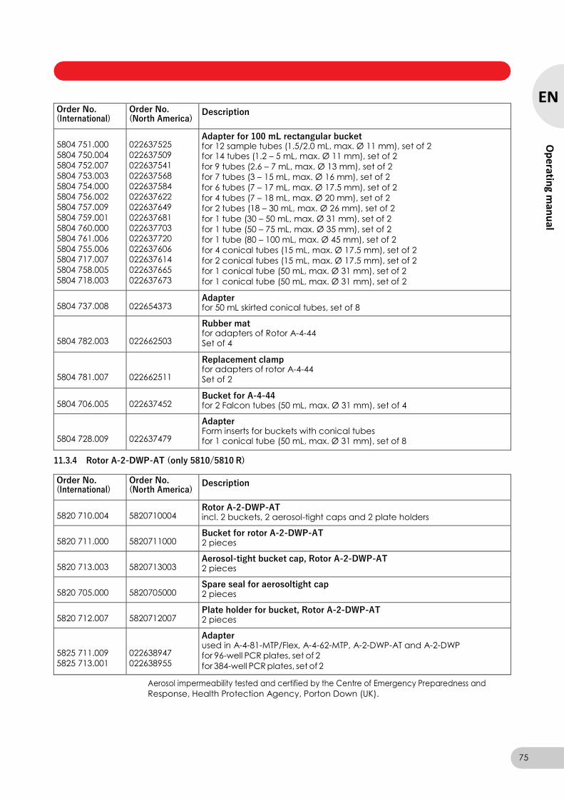
Centrifuge 5804/5804 R/5810/5810 R — Operating manual
Order No. (International)
Order No. (North America)
Description
5804 751.000
5804 750.004
5804 752.007
5804 753.003
5804 754.000
5804 756.002
5804 757.009
5804 759.001
5804 760.000
5804 761.006
5804 755.006
5804 717.007
5804 758.005
5804 718.003
022637525
022637509
022637541
022637568
022637584
022637622
022637649
022637681
022637703
022637720
022637606
022637614
022637665
022637673
Adapter for 100 mL rectangular bucket for 12 sample tubes (1.5/2.0 mL, max. Ø 11 mm), set of 2 for 14 tubes (1.2 – 5 mL, max. Ø 11 mm), set of 2
for 9 tubes (2.6 – 7 mL, max. Ø 13 mm), set of 2
for 7 tubes (3 – 15 mL, max. Ø 16 mm), set of 2
for 6 tubes (7 – 17 mL, max. Ø 17.5 mm), set of 2
for 4 tubes (7 – 18 mL, max. Ø 20 mm), set of 2
for 2 tubes (18 – 30 mL, max. Ø 26 mm), set of 2
for 1 tube (30 – 50 mL, max. Ø 31 mm), set of 2
for 1 tube (50 – 75 mL, max. Ø 35 mm), set of 2
for 1 tube (80 – 100 mL, max. Ø 45 mm), set of 2
for 4 conical tubes (15 mL, max. Ø 17.5 mm), set of 2
for 2 conical tubes (15 mL, max. Ø 17.5 mm), set of 2
for 1 conical tube (50 mL, max. Ø 31 mm), set of 2
for 1 conical tube (50 mL, max. Ø 31 mm), set of 2
5804 737.008
022654373 Adapter for 50 mL skirted conical tubes, set of 8
5804 782.003
022662503
Rubber mat for adapters of Rotor A-4-44 Set of 4
5804 781.007
022662511
Replacement clamp for adapters of rotor A-4-44 Set of 2
5804 706.005
022637452 Bucket for A-4-44 for 2 Falcon tubes (50 mL, max. Ø 31 mm), set of 4
5804 728.009
022637479
Adapter Form inserts for buckets with conical tubes for 1 conical tube (50 mL, max. Ø 31 mm), set of 8
11.3.4 Rotor A-2-DWP-AT (only 5810/5810 R)
Order No. (International)
Order No. (North America)
Description
5820 710.004
5820710004 Rotor A-2-DWP-AT incl. 2 buckets, 2 aerosol-tight caps and 2 plate holders
5820 711.000
5820711000 Bucket for rotor A-2-DWP-AT 2 pieces
5820 713.003
5820713003 Aerosol-tight bucket cap, Rotor A-2-DWP-AT 2 pieces
5820 705.000
5820705000 Spare seal for aerosoltight cap 2 pieces
5820 712.007
5820712007 Plate holder for bucket, Rotor A-2-DWP-AT 2 pieces
5825 711.009
5825 713.001
022638947
022638955
Adapter used in A-4-81-MTP/Flex, A-4-62-MTP, A-2-DWP-AT and A-2-DWP
for 96-well PCR plates, set of 2
for 384-well PCR plates, set of 2
Aerosol impermeability tested and certified by the Centre of Emergency Preparedness and
Response, Health Protection Agency, Porton Down (UK).
75
EN
Op
erating m
anu
al
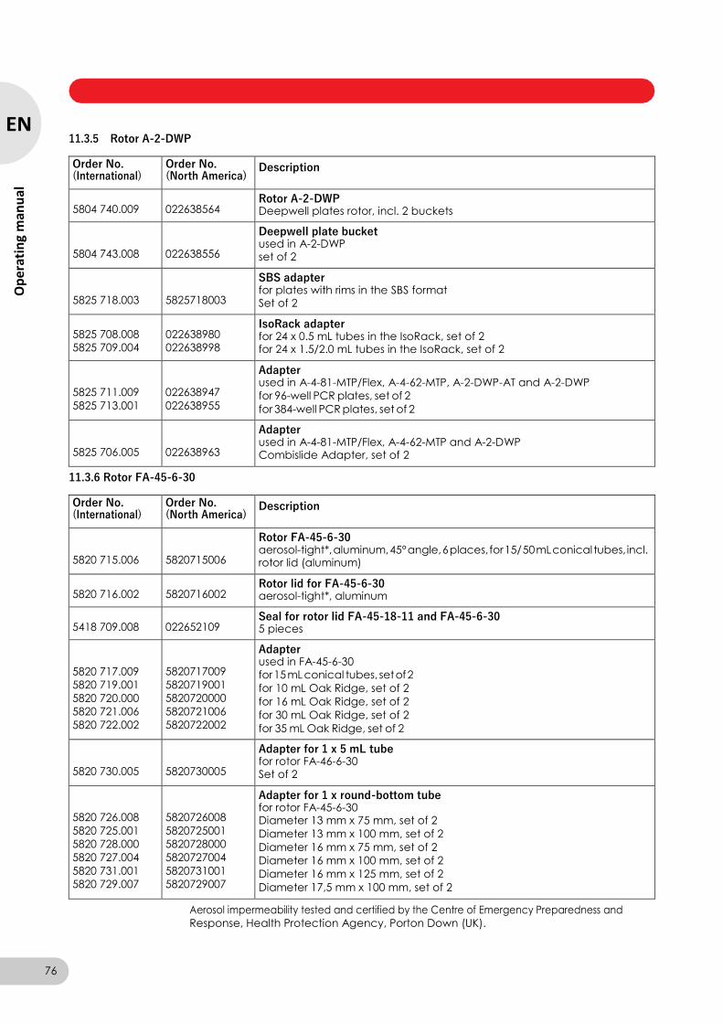
Centrifuge 5804/5804 R/5810/5810 R — Operating manual
11.3.5 Rotor A-2-DWP
Order No. (International)
Order No. (North America)
Description
5804 740.009
022638564 Rotor A-2-DWP Deepwell plates rotor, incl. 2 buckets
5804 743.008
022638556
Deepwell plate bucket used in A-2-DWP set of 2
5825 718.003
5825718003
SBS adapter for plates with rims in the SBS format Set of 2
5825 708.008
5825 709.004
022638980
022638998
IsoRack adapter for 24 x 0.5 mL tubes in the IsoRack, set of 2 for 24 x 1.5/2.0 mL tubes in the IsoRack, set of 2
5825 711.009
5825 713.001
022638947
022638955
Adapter used in A-4-81-MTP/Flex, A-4-62-MTP, A-2-DWP-AT and A-2-DWP
for 96-well PCR plates, set of 2
for 384-well PCR plates, set of 2
5825 706.005
022638963
Adapter used in A-4-81-MTP/Flex, A-4-62-MTP and A-2-DWP Combislide Adapter, set of 2
11.3.6 Rotor FA-45-6-30
Order No. (International)
Order No. (North America)
Description
5820 715.006
5820715006
Rotor FA-45-6-30 aerosol-tight*, aluminum, 45° angle, 6 places, for 15/ 50 mL conical tubes, incl. rotor lid (aluminum)
5820 716.002
5820716002 Rotor lid for FA-45-6-30 aerosol-tight*, aluminum
5418 709.008
022652109 Seal for rotor lid FA-45-18-11 and FA-45-6-30 5 pieces
5820 717.009
5820 719.001
5820 720.000
5820 721.006
5820 722.002
5820717009
5820719001
5820720000
5820721006
5820722002
Adapter used in FA-45-6-30
for 15 mL conical tubes, set of 2
for 10 mL Oak Ridge, set of 2
for 16 mL Oak Ridge, set of 2
for 30 mL Oak Ridge, set of 2
for 35 mL Oak Ridge, set of 2
5820 730.005
5820730005
Adapter for 1 x 5 mL tube for rotor FA-46-6-30 Set of 2
5820 726.008
5820 725.001
5820 728.000
5820 727.004
5820 731.001
5820 729.007
5820726008
5820725001
5820728000
5820727004
5820731001
5820729007
Adapter for 1 x round-bottom tube for rotor FA-45-6-30 Diameter 13 mm x 75 mm, set of 2
Diameter 13 mm x 100 mm, set of 2
Diameter 16 mm x 75 mm, set of 2
Diameter 16 mm x 100 mm, set of 2
Diameter 16 mm x 125 mm, set of 2
Diameter 17,5 mm x 100 mm, set of 2
Aerosol impermeability tested and certified by the Centre of Emergency Preparedness and
Response, Health Protection Agency, Porton Down (UK).
76
EN
Op
erat
ing
man
ual

Centrifuge 5804/5804 R/5810/5810 R — Operating manual
11.3.7 Rotor F-34-6-38
Order No. (International)
Order No. (North America)
Description
5804 727.002
022637207 Rotor F-34-6-38 34° angle, 6 places for 85 mL tubes, incl. rotor lid
5804 727.509 022662961 Rotor lid for F-34-6-38
5804 770.005
5804 738.004
5804 739.000
5804 771.001
5804 776.003
5804 772.008
5804 773.004
5804 774.000
5804 775.007
022637215
022637279
022637282
022637223
022637274
022637231
022637240
022637258
022637266
Adapter used in F-34-6-38 for 4 sample tubes 1.5/2.0 mL (max. Ø 11 mm), set of 2
for 3 round-bottom and blood collection tubes (13 x 75 mm), set of 2
for 3 round-bottom and blood collection tubes (13 x 100 mm),set of 2
for 2 tubes (7 bis 15 mL, max. Ø 16 mm), set of 2
for 1 conical tube (15 mL, max. Ø 17 mm), set of 2
for 1 tube (15 bis 18 mL, max. Ø 18 mm), set of 2
for 1 tube (20 bis 30 mL, max. Ø 26 mm), set of 2
for 1 tube (50 mL, max. Ø 29 mm), set of 2
for 1 conical tube (50 mL, max. Ø 29.5 mm), set of 2
11.3.8 Rotor FA-45-30-11 and Rotor F-45-30-11
Order No. (International)
Order No. (North America)
Description
5804 726.006
022637100 Rotor FA-45-30-11 aerosol-tight*, 45° angle, 30 places for 1.5/2.0 mL tubes, incl. rotor lid (aluminum)
5804 736.001
022637126 Rotor lid for FA-45-30-11 aerosol-tight*, aluminum
5804 715.004
022637002 Rotor F 45-30-11 45° angle, 30 places for 1.5/2.0 mL tubes, incl. rotor lid (aluminum)
5804 715.403
022662970 Rotor lid for F-45-30-11 not aerosol-tight, aluminum
5425 715.005
5425 717.008
5425 716.001
022636260
022636243
022636227
Adapter used in FA-45-30-11 and F-45-30-11 for 1 PCR tube (0.2 mL, max. Ø 6 mm), set of 6
for 1 sample tube (0.4 mL, max. Ø 6 mm), set of 6
for 1 sample tube (0.5 mL, max. Ø 6 mm) or 1 Microtainer (0.6 mL,
max. Ø 8 mm), set of 6
11.3.9 Rotor F-45-48-PCR
Order No. (International)
Order No. (North America)
Description
5804 735.005
022638581 Rotor F-45-48-PCR 45° angle, for 6 x 8-tube strips, 6 x 5-tube strips or 48 x 0.2 mL PCR tubes
11.3.10 Rotor T-60-11
Order No. (International)
Order No. (North America)
Description
5804 730.003
022638505
Rotor T 60-11 for 60 x 1.5/2.0 mL tubes incl. rotor lid, and 6 adapters for 1.5/2 mL sample tubes
77
EN
Op
erating m
anu
al
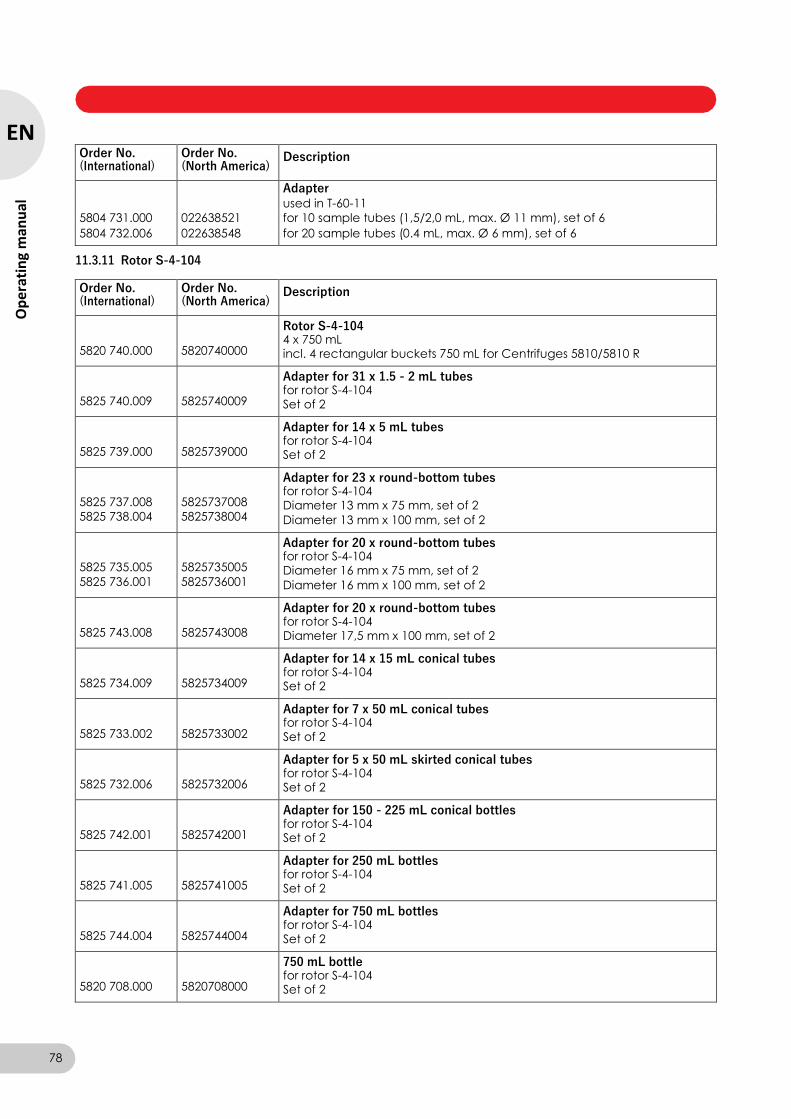
Centrifuge 5804/5804 R/5810/5810 R — Operating manual
Order No. (International)
Order No. (North America)
Description
Adapter used in T-60-11
5804 731.000 022638521 for 10 sample tubes (1,5/2,0 mL, max. Ø 11 mm), set of 6
5804 732.006 022638548 for 20 sample tubes (0.4 mL, max. Ø 6 mm), set of 6
11.3.11 Rotor S-4-104
Order No. (International)
Order No. (North America)
Description
5820 740.000
5820740000
Rotor S-4-104 4 x 750 mL incl. 4 rectangular buckets 750 mL for Centrifuges 5810/5810 R
5825 740.009
5825740009
Adapter for 31 x 1.5 - 2 mL tubes for rotor S-4-104 Set of 2
5825 739.000
5825739000
Adapter for 14 x 5 mL tubes for rotor S-4-104 Set of 2
5825 737.008
5825 738.004
5825737008
5825738004
Adapter for 23 x round-bottom tubes for rotor S-4-104 Diameter 13 mm x 75 mm, set of 2
Diameter 13 mm x 100 mm, set of 2
5825 735.005
5825 736.001
5825735005
5825736001
Adapter for 20 x round-bottom tubes for rotor S-4-104 Diameter 16 mm x 75 mm, set of 2
Diameter 16 mm x 100 mm, set of 2
5825 743.008
5825743008
Adapter for 20 x round-bottom tubes for rotor S-4-104 Diameter 17,5 mm x 100 mm, set of 2
5825 734.009
5825734009
Adapter for 14 x 15 mL conical tubes for rotor S-4-104 Set of 2
5825 733.002
5825733002
Adapter for 7 x 50 mL conical tubes for rotor S-4-104 Set of 2
5825 732.006
5825732006
Adapter for 5 x 50 mL skirted conical tubes for rotor S-4-104 Set of 2
5825 742.001
5825742001
Adapter for 150 - 225 mL conical bottles for rotor S-4-104 Set of 2
5825 741.005
5825741005
Adapter for 250 mL bottles for rotor S-4-104 Set of 2
5825 744.004
5825744004
Adapter for 750 mL bottles for rotor S-4-104 Set of 2
5820 708.000
5820708000
750 mL bottle for rotor S-4-104 Set of 2
78
EN
Op
erat
ing
man
ual
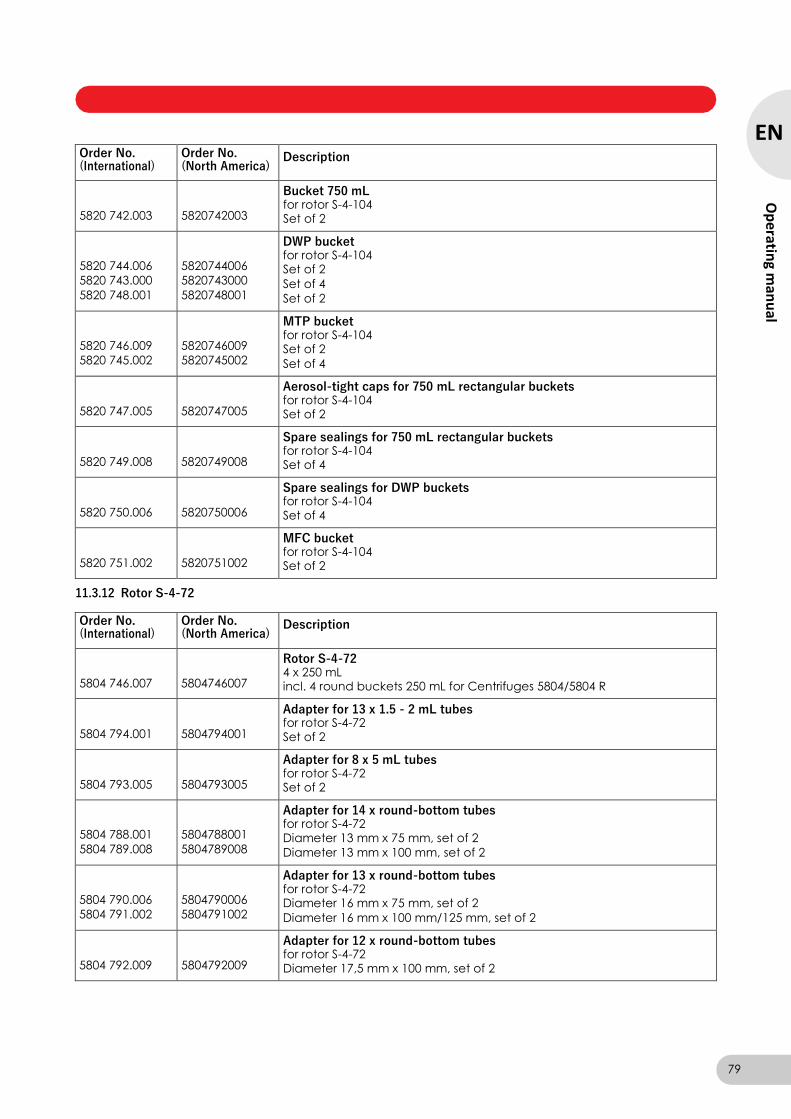
Centrifuge 5804/5804 R/5810/5810 R — Operating manual
Order No. (International)
Order No. (North America)
Description
5820 742.003
5820742003
Bucket 750 mL for rotor S-4-104 Set of 2
5820 744.006
5820 743.000
5820 748.001
5820744006
5820743000
5820748001
DWP bucket for rotor S-4-104 Set of 2
Set of 4
Set of 2
5820 746.009
5820 745.002
5820746009
5820745002
MTP bucket for rotor S-4-104 Set of 2
Set of 4
5820 747.005
5820747005
Aerosol-tight caps for 750 mL rectangular buckets for rotor S-4-104 Set of 2
5820 749.008
5820749008
Spare sealings for 750 mL rectangular buckets for rotor S-4-104 Set of 4
5820 750.006
5820750006
Spare sealings for DWP buckets for rotor S-4-104 Set of 4
5820 751.002
5820751002
MFC bucket for rotor S-4-104 Set of 2
11.3.12 Rotor S-4-72
Order No. (International)
Order No. (North America)
Description
5804 746.007
5804746007
Rotor S-4-72 4 x 250 mL incl. 4 round buckets 250 mL for Centrifuges 5804/5804 R
5804 794.001
5804794001
Adapter for 13 x 1.5 - 2 mL tubes for rotor S-4-72 Set of 2
5804 793.005
5804793005
Adapter for 8 x 5 mL tubes for rotor S-4-72 Set of 2
5804 788.001
5804 789.008
5804788001
5804789008
Adapter for 14 x round-bottom tubes for rotor S-4-72 Diameter 13 mm x 75 mm, set of 2
Diameter 13 mm x 100 mm, set of 2
5804 790.006
5804 791.002
5804790006
5804791002
Adapter for 13 x round-bottom tubes for rotor S-4-72 Diameter 16 mm x 75 mm, set of 2
Diameter 16 mm x 100 mm/125 mm, set of 2
5804 792.009
5804792009
Adapter for 12 x round-bottom tubes for rotor S-4-72 Diameter 17,5 mm x 100 mm, set of 2
79
EN
Op
erating m
anu
al
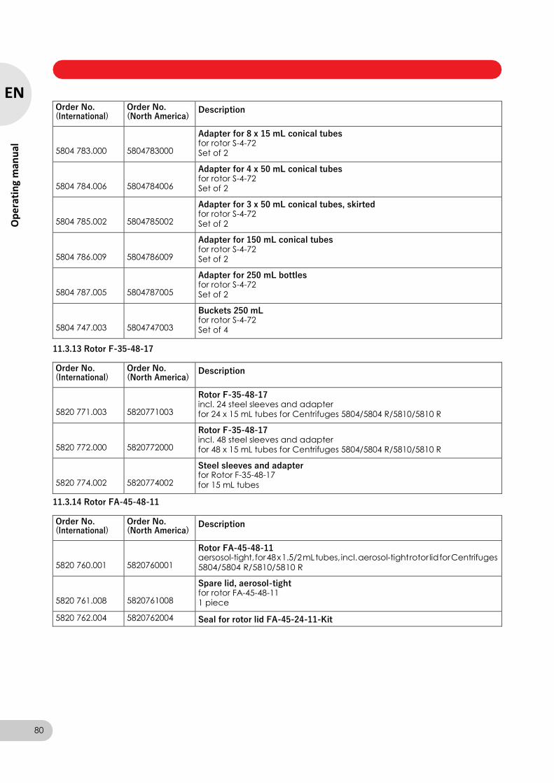
Centrifuge 5804/5804 R/5810/5810 R — Operating manual
Order No. (International)
Order No. (North America)
Description
5804 783.000
5804783000
Adapter for 8 x 15 mL conical tubes for rotor S-4-72 Set of 2
5804 784.006
5804784006
Adapter for 4 x 50 mL conical tubes for rotor S-4-72 Set of 2
5804 785.002
5804785002
Adapter for 3 x 50 mL conical tubes, skirted for rotor S-4-72 Set of 2
5804 786.009
5804786009
Adapter for 150 mL conical tubes for rotor S-4-72 Set of 2
5804 787.005
5804787005
Adapter for 250 mL bottles for rotor S-4-72 Set of 2
5804 747.003
5804747003
Buckets 250 mL for rotor S-4-72 Set of 4
11.3.13 Rotor F-35-48-17
Order No. (International)
Order No. (North America)
Description
5820 771.003
5820771003
Rotor F-35-48-17 incl. 24 steel sleeves and adapter for 24 x 15 mL tubes for Centrifuges 5804/5804 R/5810/5810 R
5820 772.000
5820772000
Rotor F-35-48-17 incl. 48 steel sleeves and adapter for 48 x 15 mL tubes for Centrifuges 5804/5804 R/5810/5810 R
5820 774.002
5820774002
Steel sleeves and adapter for Rotor F-35-48-17 for 15 mL tubes
11.3.14 Rotor FA-45-48-11
Order No. (International)
Order No. (North America)
Description
5820 760.001
5820760001
Rotor FA-45-48-11 aersosol-tight, for 48 x 1.5/2 mL tubes, incl. aerosol-tight rotor lid for Centrifuges 5804/5804 R/5810/5810 R
5820 761.008
5820761008
Spare lid, aerosol-tight for rotor FA-45-48-11 1 piece
5820 762.004 5820762004 Seal for rotor lid FA-45-24-11-Kit
80
EN
Op
erat
ing
man
ual
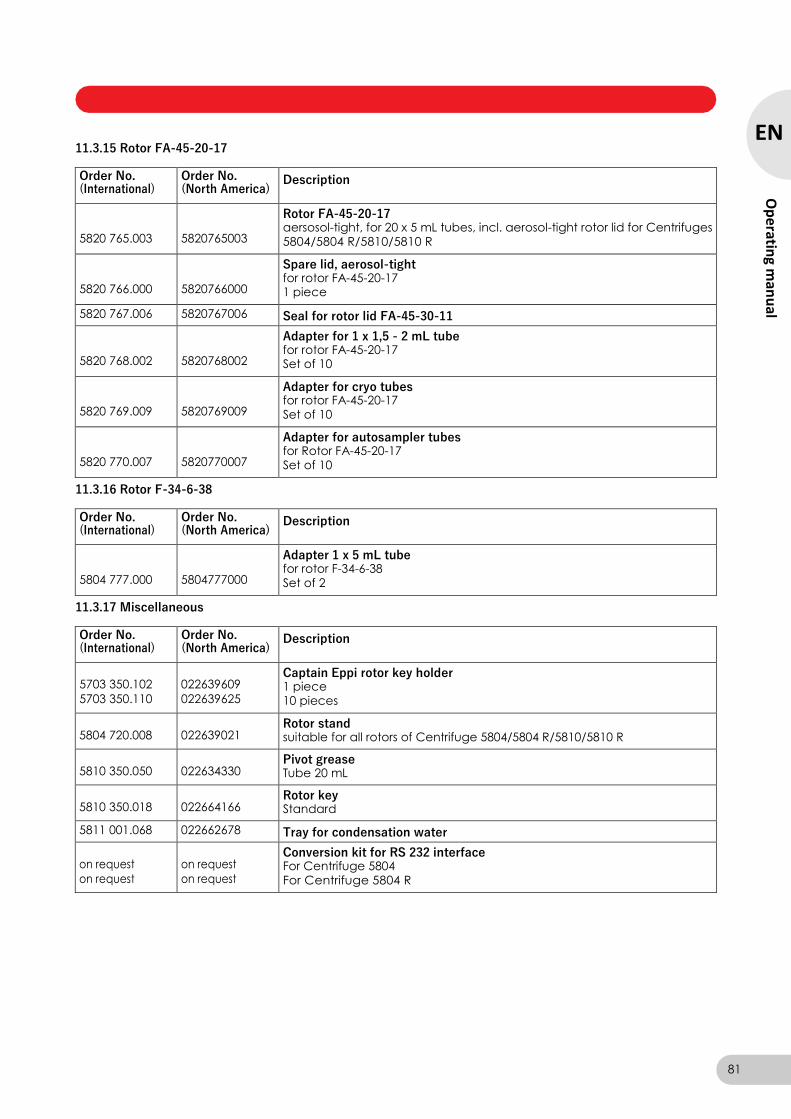
Centrifuge 5804/5804 R/5810/5810 R — Operating manual
11.3.15 Rotor FA-45-20-17
Order No. (International)
Order No. (North America)
Description
5820 765.003
5820765003
Rotor FA-45-20-17 aersosol-tight, for 20 x 5 mL tubes, incl. aerosol-tight rotor lid for Centrifuges 5804/5804 R/5810/5810 R
5820 766.000
5820766000
Spare lid, aerosol-tight for rotor FA-45-20-17 1 piece
5820 767.006 5820767006 Seal for rotor lid FA-45-30-11
5820 768.002
5820768002
Adapter for 1 x 1,5 - 2 mL tube for rotor FA-45-20-17 Set of 10
5820 769.009
5820769009
Adapter for cryo tubes for rotor FA-45-20-17 Set of 10
5820 770.007
5820770007
Adapter for autosampler tubes for Rotor FA-45-20-17 Set of 10
11.3.16 Rotor F-34-6-38
Order No. (International)
Order No. (North America)
Description
5804 777.000
5804777000
Adapter 1 x 5 mL tube for rotor F-34-6-38 Set of 2
11.3.17 Miscellaneous
Order No. (International)
Order No. (North America)
Description
5703 350.102
5703 350.110
022639609
022639625
Captain Eppi rotor key holder 1 piece 10 pieces
5804 720.008
022639021 Rotor stand suitable for all rotors of Centrifuge 5804/5804 R/5810/5810 R
5810 350.050
022634330 Pivot grease Tube 20 mL
5810 350.018
022664166 Rotor key Standard
5811 001.068 022662678 Tray for condensation water
on request
on request
on request
on request
Conversion kit for RS 232 interface For Centrifuge 5804 For Centrifuge 5804 R
81
EN
Op
erating m
anu
al
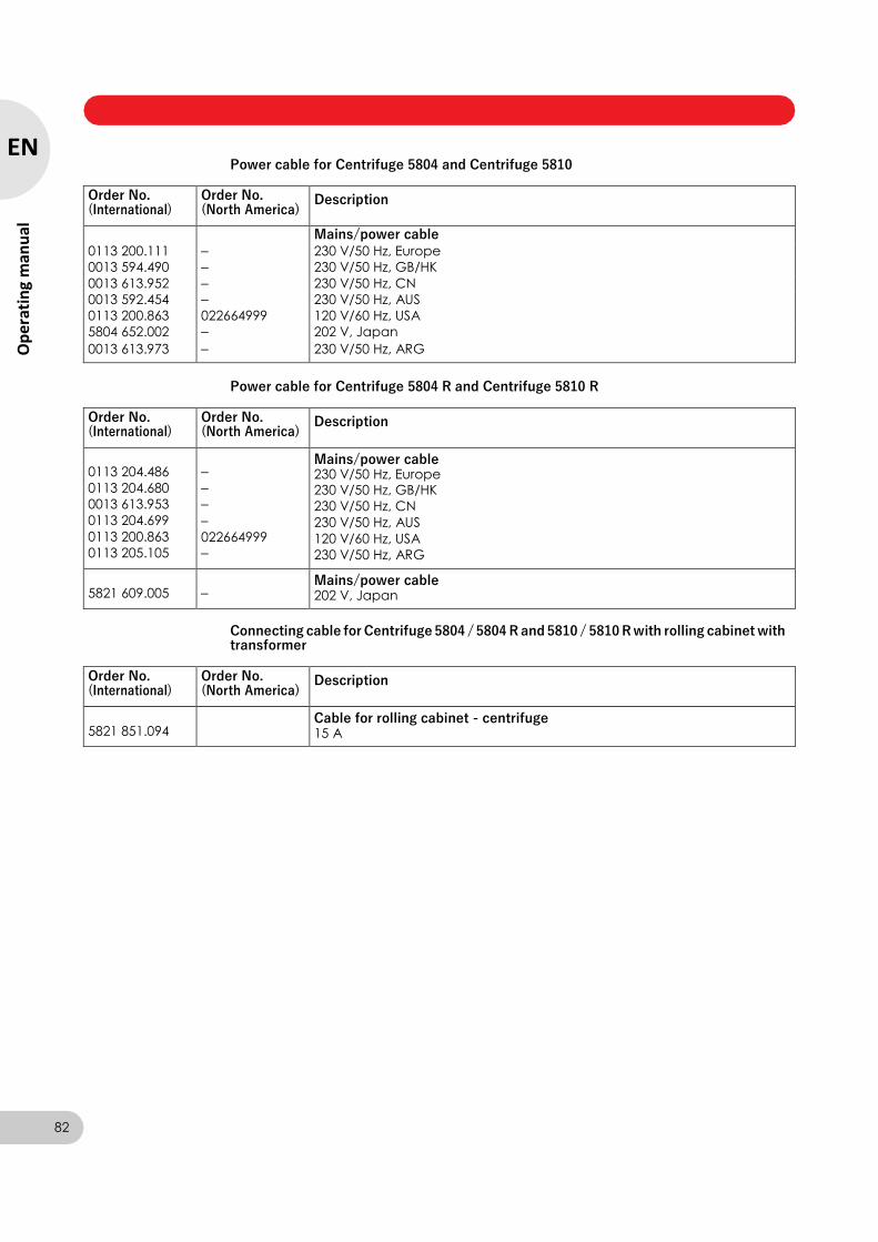
Centrifuge 5804/5804 R/5810/5810 R — Operating manual
Power cable for Centrifuge 5804 and Centrifuge 5810
Order No. (International)
Order No. (North America)
Description
Mains/power cable
0113 200.111 – 230 V/50 Hz, Europe
0013 594.490 – 230 V/50 Hz, GB/HK
0013 613.952 – 230 V/50 Hz, CN
0013 592.454 – 230 V/50 Hz, AUS
0113 200.863 022664999 120 V/60 Hz, USA
5804 652.002 – 202 V, Japan
0013 613.973 – 230 V/50 Hz, ARG
Power cable for Centrifuge 5804 R and Centrifuge 5810 R
Order No. (International)
Order No. (North America)
Description
0113 204.486
0113 204.680
0013 613.953
0113 204.699
0113 200.863
0113 205.105
–
–
–
–
022664999
–
Mains/power cable 230 V/50 Hz, Europe 230 V/50 Hz, GB/HK
230 V/50 Hz, CN
230 V/50 Hz, AUS
120 V/60 Hz, USA
230 V/50 Hz, ARG
5821 609.005
– Mains/power cable 202 V, Japan
Connecting cable for Centrifuge 5804 / 5804 R and 5810 / 5810 R with rolling cabinet with transformer
Order No. (International)
Order No. (North America)
Description
5821 851.094
Cable for rolling cabinet - centrifuge 15 A
82
EN
Op
erat
ing
man
ual

123
SV
Bru
ksan
visnin
g